

Page 1
Operator Manual
Guide De L’opérateur
Betriebsanleitung
Manual Del Operador
XRT Electric
SERIAL NO. 1001 to Current
WARNING
All personnel shall carefully read, understand and follow all safety
rules, operating instructions, and National Safety Instructions/
Requirements before operating or performing maintenance on any
UpRight Aerial Work Platform.
Refer to page 2 for the English language version of this Operator Manual.
AVERTISSEMENT
Tout le personnel doit lire attentivement et respecter toutes les
consignes de sécurité avant d’entretenir ou d’utiliser une plate-forme
élévatrice UpRight.
Reportez-vous à la page 17 pour la version française de ce guide de l’opérateur.
WARNUNG
Alle Bediener müssen die Sicherheitsregeln und
Bedienungsanleitungen gründlich durchlesen, verstehen und
befolgen, bevor sie an irgendeiner UpRight-Hocharbeitsbühne
Wartungsarbeiten ausführen oder diese in Betrieb nehmen.
Bezüglich der deutschsprachigen Ausgabe dieser Betriebsanleitung siete 32.
ADVERTENCIA
Todo el personal debe leer atentamente, entender y respetar todas las
reglas de seguridad y las instrucciones de operación antes de
efectuar trabajos de mantenimiento o manejar cualquier plataforma
aérea de trabajo UpRight.
Referirse a la página 47 para la versión en eapañol de este manual del operador.
Page 2
English Language Section
English Language Section
English Language SectionEnglish Language Section
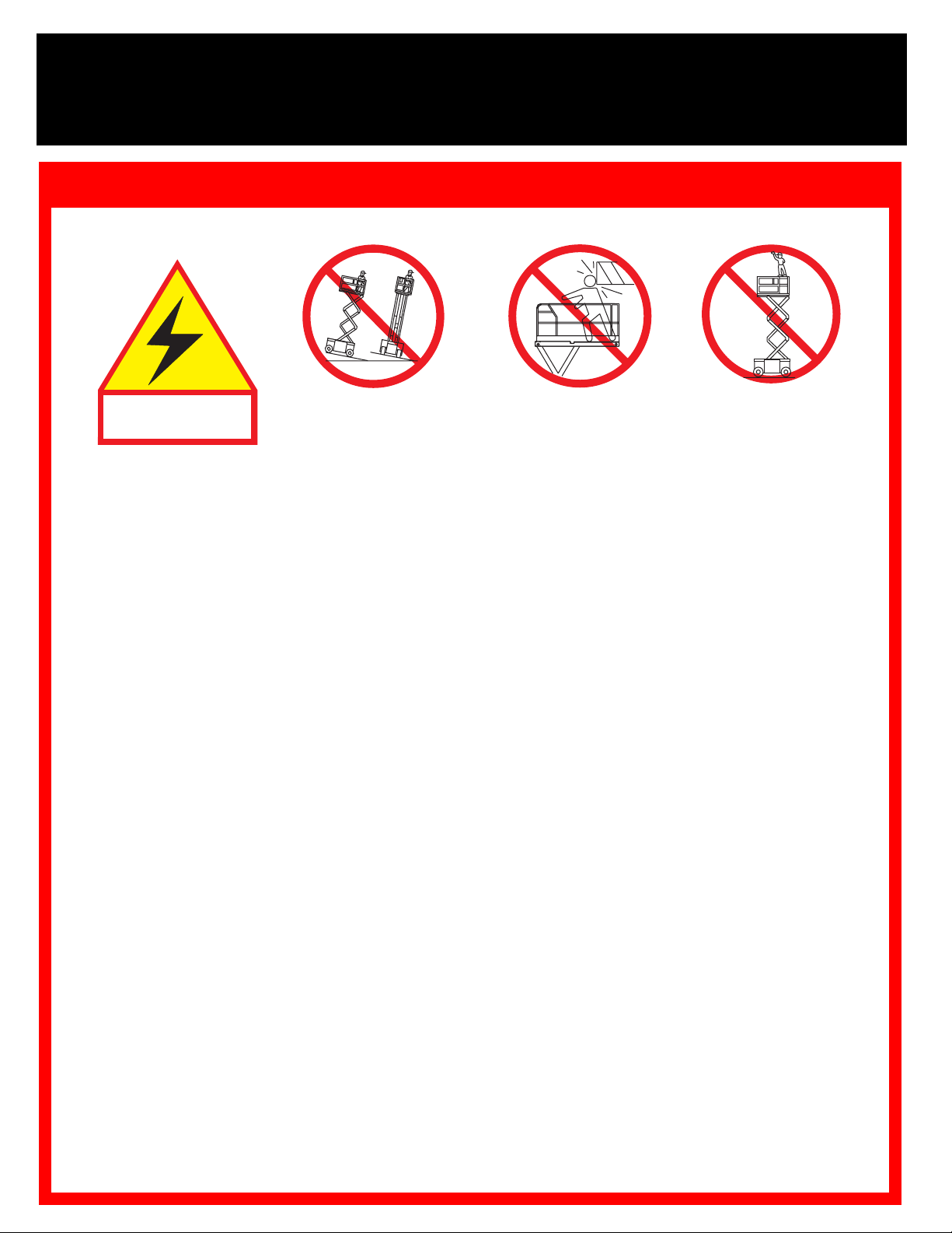
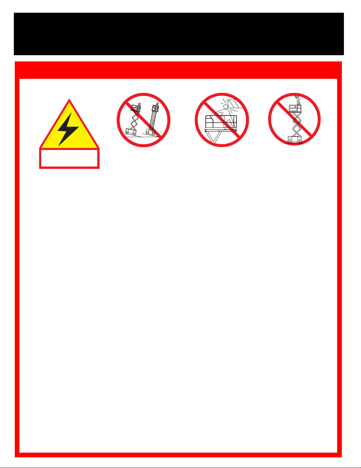
Safety Rules
Electrocution Hazard
Electrocution Hazard Tip Over Hazard
Electrocution HazardElectrocution Hazard
Tip Over Hazard Collision Hazard
Tip Over HazardTip Over Hazard
Collision Hazard Fall Hazard
Collision HazardCollision Hazard
Fall Hazard
Fall HazardFall Hazard
THIS MACHINE IS
THIS MACHINE IS
THIS MACHINE IS THIS MACHINE IS
NOT INSULATED.
NOT INSULATED.
NOT INSULATED.NOT INSULATED.
USE OF THE AERIAL WORK PLATFORM
rial used for the job. It is designed for repair and assembly jobs and assignments at overhead workplaces (ceilings, cranes, roof
structures, buildings, etc.). All other uses of the aerial work platform
THIS AERIAL WORK PLATFORM IS NOT INSULATED!
electrical equipment!
Exceeding the specified permissible maximum load on the platform
The use and operation of the aerial work platform as a lifting tool or a crane (lifting of loads from below upwards or from up high on
is prohibited!
down)
NEVER
DISTRIBUTE
NEVER
debris; and avoiding them.
operate the machine
NEVER
IN CASE OF EMERGENCY
Climbing up the railing of the platform, standing on or stepping from the platform onto buildings, steel or prefab concrete structures,
etc.,
Dismantling the swing gate or other railing components
securely locked!
It is prohibited
To extend the height or the range by placing of ladders, scaffolds or similar devices on the platform
NEVER
INSPECT
aged cables or hoses before using.
VERIFY
NEVER
IF ALARM SOUNDS
To bypass any safety equipment
range.
NEVER
Modifications to the aerial work platform
AFTER USE
exceed 400 N (90 lbs.) of side force.
all platform loads evenly on the platform.
operate the machine without first surveying the work area for surface hazards such as holes, drop-offs, bumps, curbs, or
operate the machine when wind speeds exceed 45 km/h (28 mph) (12,5 m/sec.= Beaufort scale 6).
is prohibited!
to keep the swing gate in an open position (held open with tie-straps) when the platform is raised!
perform service on the machine while the platform is elevated without supporting the elevating assembly.
the machine thoroughly for cracked welds, loose or missing hardware, hydraulic leaks, loose wire connections, and dam-
that all labels are in place and legible before using.
use a machine that is damaged, not functioning properly, or has damaged or missing labels.
charge batteries near sparks or open flame. Charging batteries emit explosive hydrogen gas.
, secure the work platform from unauthorized use by turning both keyswitches off and removing the key.
XRT27E 567 kg (1250 lbs.) including four (4) persons
XRT33E 454 kg (1000 lbs.) including three (3) persons
only on surfaces capable of supporting wheel loads.
while the platform is elevated, STOP, carefully lower the platform. Move the machine to a firm, level surface.
NEVER
or drive the machine with the
platform elevated unless on
push EMERGENCY STOP button to deactivate all powered functions.
is prohibited
elevate the platform
firm, level surface.
: This aerial work platform is intended to lift persons and their tools as well as the mate-
For this reason it is imperative to keep a safe distance from live parts of
is prohibited!
and presents a danger for the persons on the aerial work platform and in its working
are prohibited
or permissible only at the approval of UpRight.
NEVER
are prohibited!
is prohibited!
position the platform
without first checking for
overhead obstructions or
other hazards.
Always make certain that the swing gate is closed and
NEVER
is prohibited!
climb, stand or
sit on the platform
guardrails or midrail.
Page 3
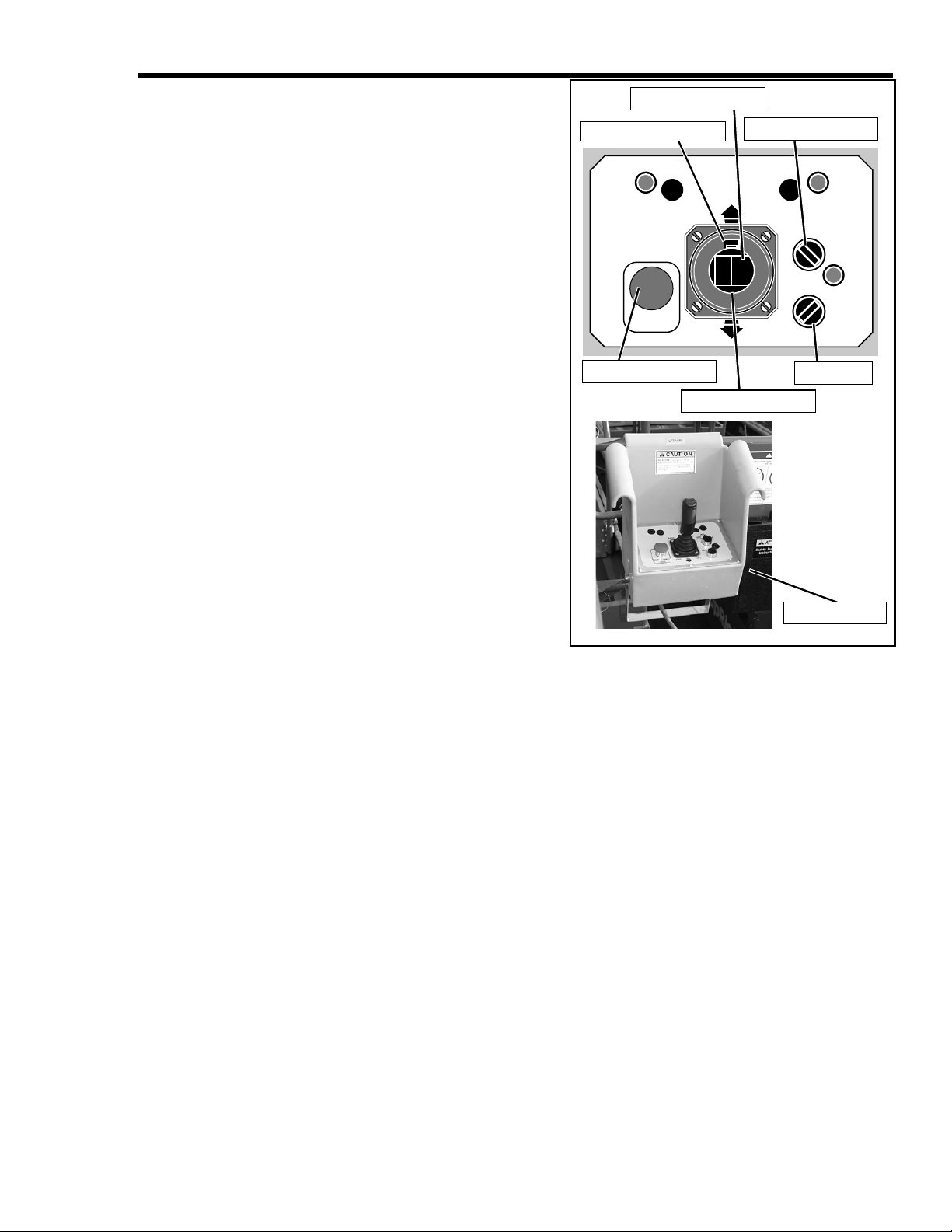
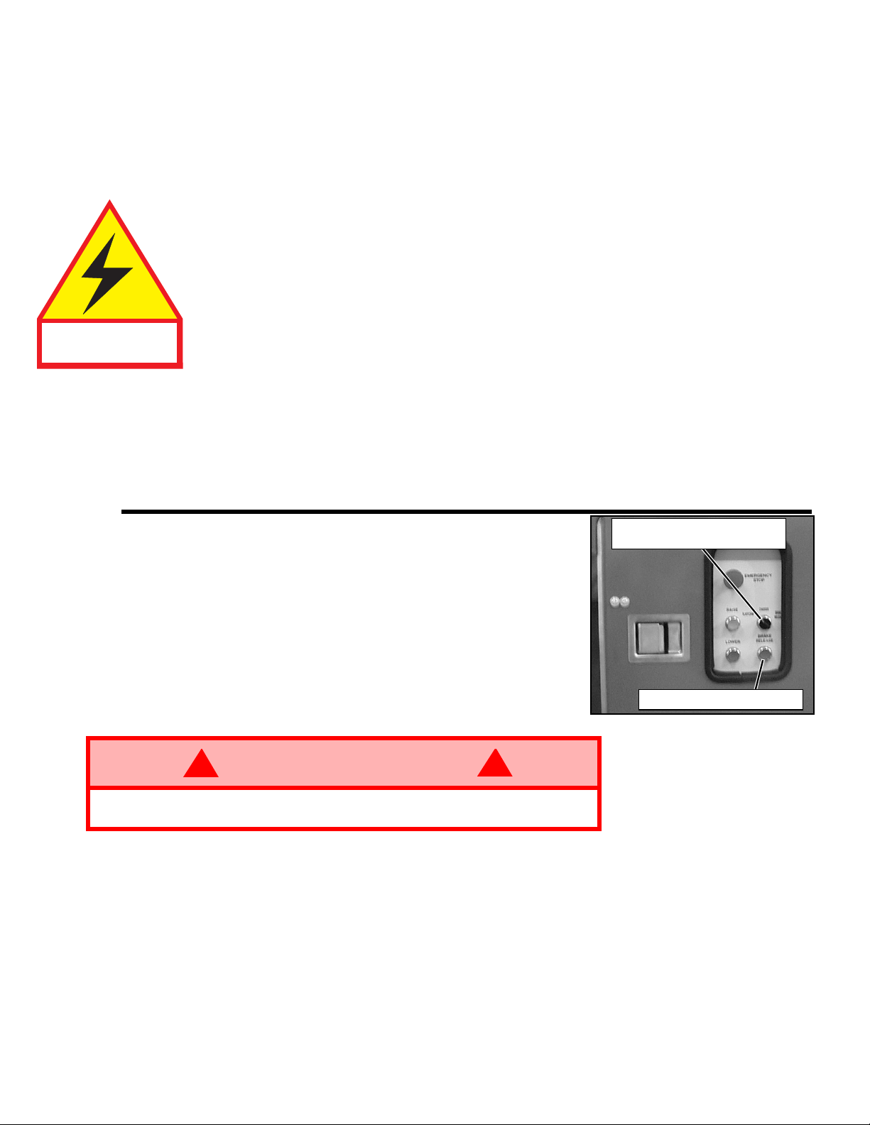
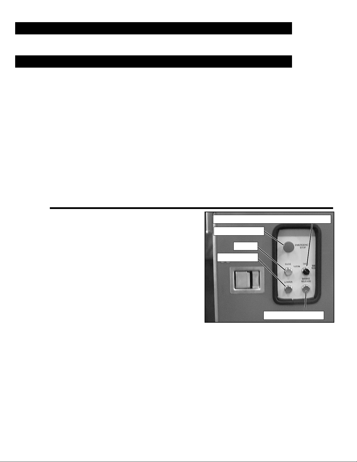
I
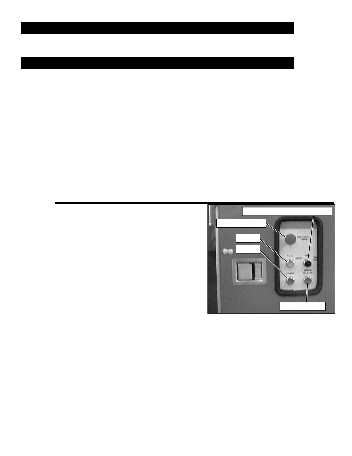
EMERGENCY STOP
PLATFORM/CHASSIS/BRAKE RELEASE
RAISE
BRAKE RELEASE
LOWER
NTRODUCTION
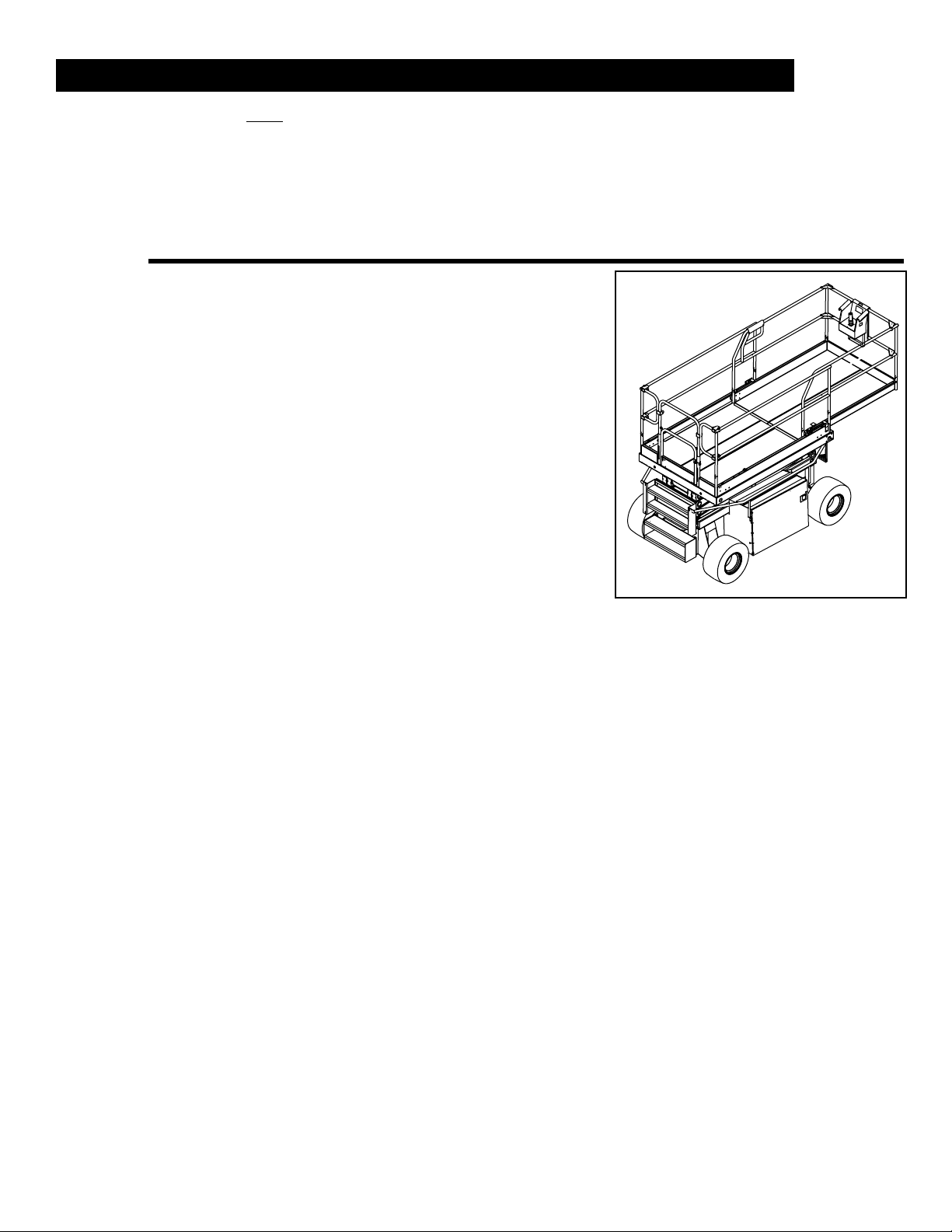
This manual covers the XRT Self-Propelled Electric Work Platforms. This machine operates on a
48 volt battery powered system.
This manual must be stored on the machine at all times.
PRE-O
PERATION AND SAFETY INSPECTION
Carefully read, understand and follow all safety rules, operating instructions, labels, and the Scaffold Industry Association’s MANUAL OF RESPONSIBILITIES. Perform the following steps each
day before use.
1. Open module covers and inspect for damage, oil leaks or missing parts.
2. Check the hydraulic oil level sight gauge on the hydraulic tank with the platform fully lowered.
3. Check that fluid level in the batteries is correct (see "Battery Maintenance" on page 13).
4. Check that all guardrails are in place with all fasteners properly tightened.
5. Check that the slide-out deck extension is secured with the pin.
6. Check tires for damage.
7. Inspect the machine thoroughly for cracked welds, loose or missing hardware, hydraulic
8. Close and secure module covers.
9. Move the machine, if necessary, to an unobstructed area to allow for full elevation.
10. Pull the Chassis Emergency Stop Switch to the ON position.
11. Pull the Platform Emergency Stop Switch to the ON position.
12. Turn the Platform Controls Key Switch
13. Use the Chassis Controls for steps 14
14. Turn the Platform/Chassis/Brake Release
15. Push the Chassis Controls RAISE button
16. Visually inspect the elevating assembly,
17. Remove the Scissor Brace as described
18. Push the Chassis Controls RAISE button to fully elevate the platform.
19. Lower the platform partially by pushing in on the Chassis Controls LOWER button, and check
20. Push the Chassis Emergency Stop button to check for proper operation. All the machine func-
Add hydraulic oil if necessary.
leaks, damaged control cable, loose wire connections and wheel bolts.
Figure 1:
clockwise to ON.
through 20.
Switch to CHASSIS.
to elevate the platform until the Scissor
Brace can be rotated to the vertical position. Block the elevating assembly as
described on page 12.
lift cylinder, cables and hoses for damage
or erratic operation. Check for missing or
loose parts.
on page 12.
operation of the audible lowering alarm.
tions should be disabled. Pull out the Emergency Stop button to resume.
Chassis Controls
3XRT Electric
Page 4
21. Check the Emergency Lowering system for proper
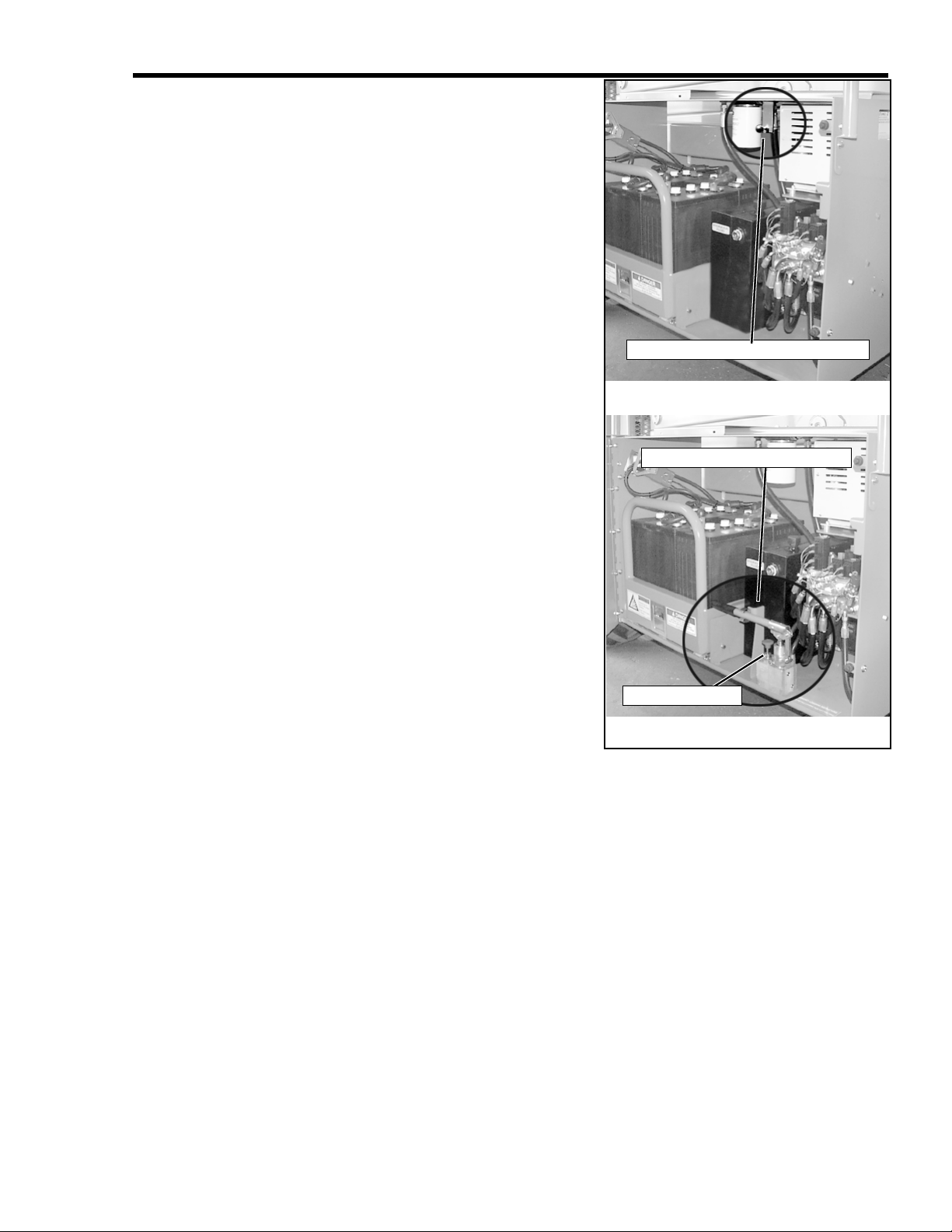
XRT27E
XRT33E
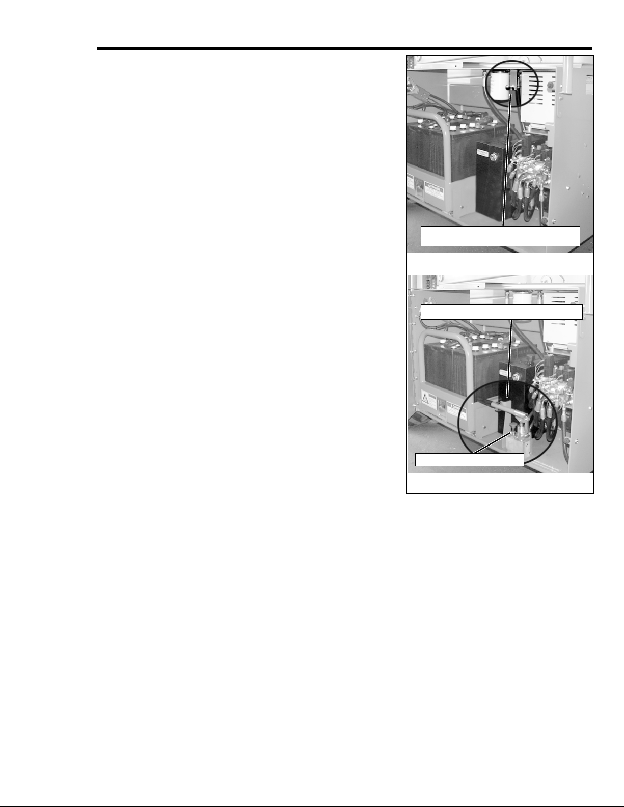
EMERGENCY LOWERING VALVE
EMERGENCY LOWERING VALVE KNOB
CONTROL VALVE
operation.
A. XRT27E – The Emergency Lowering Valve
Knob is located in the Power Module, above the
hydraulic oil tank.
a. Open the Power Module Cover.
b. Open the Emergency Lowering Valve by
pulling and holding the knob.
c. Once the platform is completely lowered,
release the knob to close the valve.
The
platform will not elevate if the Emergency Lowering Valve is open.
d. Close and secure the Power Module cover.
B. XRT33E – The Emergency Lowering Valve is
located in the Power Module, next to the
hydraulic oil tank.
a. Open the Power Module cover.
b. Hold the control valve in the closed position,
then pump up pressure to release holding
valves on the cylinders.
c. Once the platform is fully lowered, release
the control valve to close the holding valves.
The platform will not elevate if the Emergency Lowering Valve is open.
d. Close and secure the Power Module cover.
22. Turn the Platform/Chassis Switch to PLATFORM.
23. Check that the route is clear of obstacles (persons,
obstructions, holes, drop-offs, bumps, and debris),
is level, and capable of supporting the wheel loads.
24. Mount the platform and properly close the
entrance.
25. Use the Platform Controls for the remaining steps.
Figure 2:
Emergency Lowering
4 XRT Electric
Page 5
LOW
BATTERY
MOTOR
TEMPERATURE
HIGH
SPEED
LOW
SPEED
LIFT
DRIVE
RAISE FWD.
LOWER
REV.
EMERGENCY
STOP
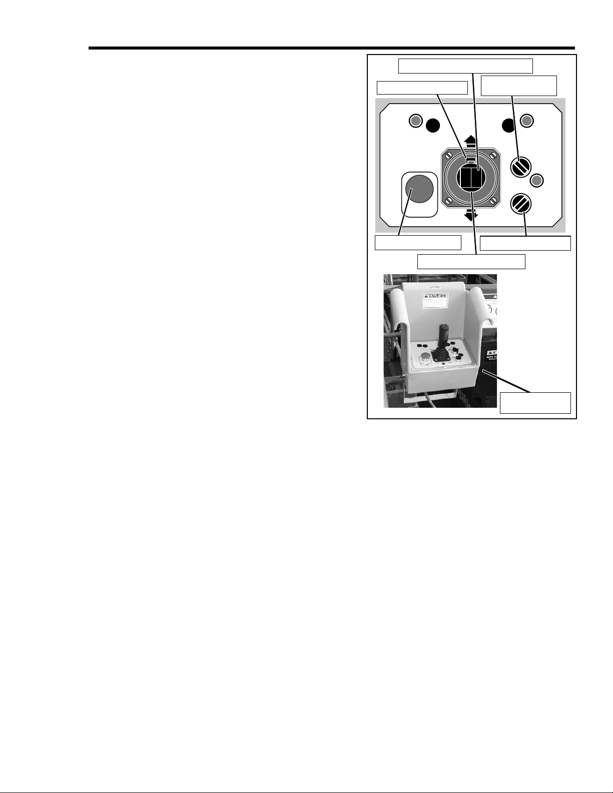
EMERGENCY STOP
INTERLOCK SWITCH
STEERING SWITCH
CONTROL HANDLE
LIFT/DRIVE
SPEED SELECTOR
KEY SWITCH
26. Turn the Lift/Drive Switch to DRIVE.
NOTE:The Speed Range Selector Switch
has two positions: HIGH SPEED and
LOW SPEED. Perform Step 27 for each
speed.
27. Engage the Interlock Switch and slowly
push the Control Handle FORWARD, then
REVERSE, to check for proportional speed
control.
28. Push the Steering Switch RIGHT, then
LEFT, to check for steering control.
29. Turn the Lift/Drive Switch to LIFT.
30. Engage the Interlock Switch and slowly
push the Control Handle forward to check
the platform lift controls. Raise the platform
to full elevation.
31. Pull back on the Control Handle. The platform should descend and the Audible Lowering Alarm should sound.
32. Lower the platform completely.
33. Push the Platform Emergency Stop button
to check for proper operation. All the
machine functions should be disabled. Pull
out the Platform Emergency Stop button to
resume.
34. Turn the Platform Controls key switch to
OFF.
35. Push the Platform Emergency Stop button
to the OFF position.
36. Dismount the platform.
37. Push the Chassis Emergency Stop button to
the OFF position.
Figure 3:
Platform Controls
5XRT Electric
Page 6
O
PERATION
operating the work platform, ensure that the pre-operation safety inspection has been
Before
completed, and that any deficiencies have been corrected.
functioning machine.
fully understand, and follow this Operator Manual and National Safety Instructions/Requirements.
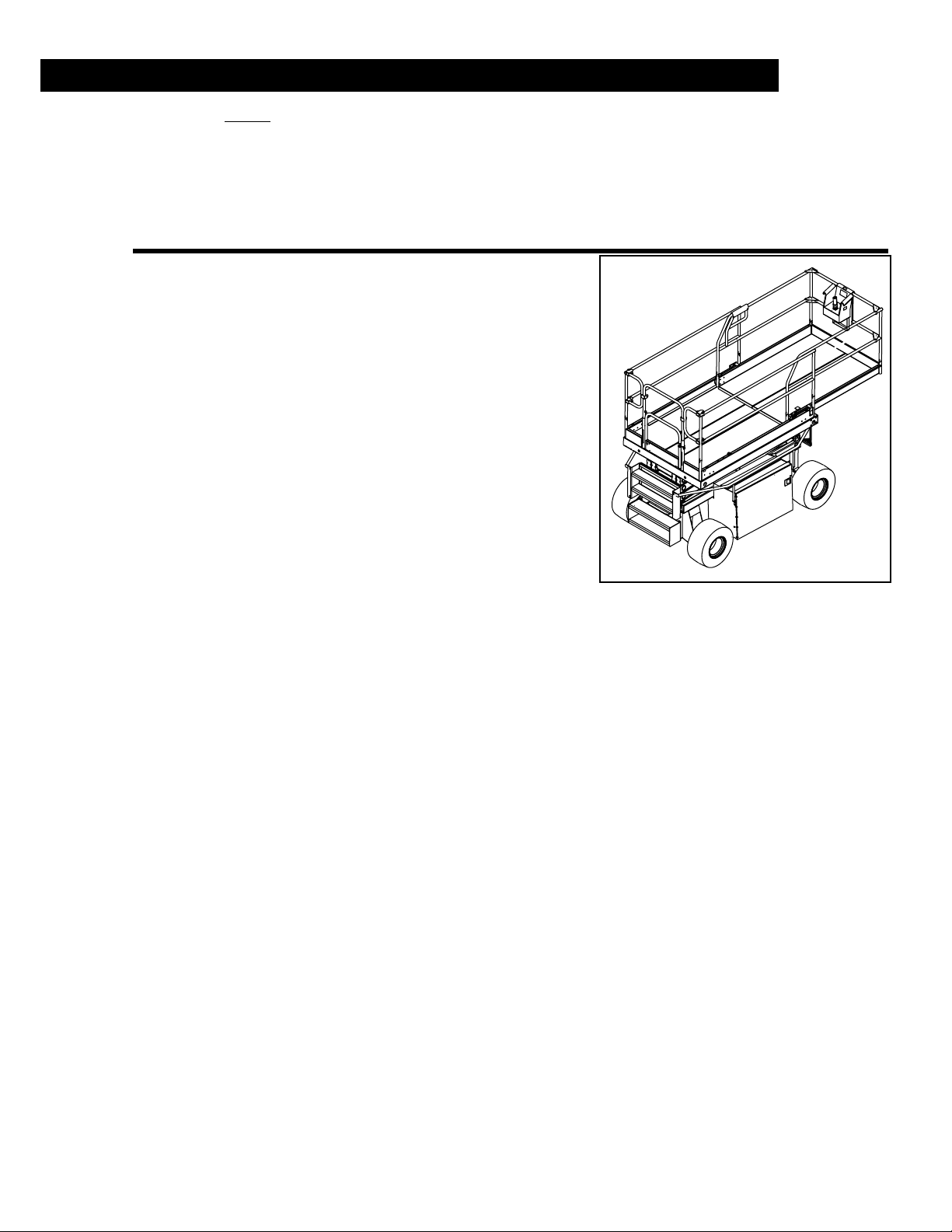
LATFORM EXTENSION
P
The operator must be thoroughly trained on this machine, and must read,
Never operate a damaged or mal-
Figure 4:
1. Mount the platform and properly close the
entrance.
2. Depress the foot lever located at the rear of the
platform extension. Push the platform extension
forward until the pin engages the front stop.
3. To retract the platform extension, depress the foot
lever and pull the platform extension toward the
rear of the machine until the pin engages the rear
stop.
RAVEL WITH PLATFORM LOWERED
T
1. Check that the route is clear of obstacles (persons, obstructions, holes, drop-offs, bumps, and
debris), is level, and capable of supporting the
wheel loads.
2. Turn the Platform/Chassis/Brake Release Switch
to PLATFORM.
3. Pull the Chassis Emergency Stop Switch to the
ON position.
4. Mount the platform and properly close the entrance.
5. Check clearances above, below and to the sides of the platform.
6. Pull the Platform Emergency Stop Switch to the ON position.
7. Turn the Platform Controls key switch to the ON position.
8. Turn the Lift/Drive Switch to DRIVE.
9. Set the Speed Range Selector Switch to the HIGH SPEED position.
10. Engage the Interlock Switch and move the Control Handle to FORWARD or REVERSE to
travel in the desired direction. The speed of the machine will vary depending on how far from
center the Control Handle is moved.
11. Turn the Speed Range Selector Switch to HIGH SPEED for travel on level surfaces.
12. Turn the Speed Range Selector Switch to LOW SPEED for climbing grades or traveling in confined areas.
Platform Extension
TEERING
S
1. Turn the Lift/Drive switch to DRIVE.
2. Engage the Interlock Switch, push the Steering Switch RIGHT or LEFT to turn the wheels in
the desired direction. Observe the tires while operating the machine to ensure proper direction.
NOTE:Steering is not self-centering. Wheels must be returned to the straight ahead
position by operating the Steering Switch.
6 XRT Electric
Page 7

LEVATING THE PLATFORM
E
1. Select a firm, level surface.
2. Turn the Lift/Drive Switch to LIFT.
3. Engage the Interlock Switch and push the Control Handle forward.
4. If the machine is not level, the tilt alarm will sound and the machine will not lift or drive.
tilt alarm, sounds the platform must be lowered and the machine moved to a firm, level
surface before attempting to re-elevate the platform.
RAVEL WITH WORK PLATFORM ELEVATED
T
NOTE:The machine will travel at reduced speed when the platform is elevated.
1. Check that the route is clear of obstacles (persons, obstructions, holes, drop-offs, bumps, and
debris), is level, and capable of supporting the wheel loads.
2. Check clearances above, below, and to the sides of the platform.
3. Turn the Lift/Drive Switch to DRIVE.
4. Set the Speed Range Selector Switch to the HIGH SPEED position.
5. Engage the Interlock Switch and move the Control Handle to FORWARD or REVERSE to
travel in the desired direction. The speed of the machine will vary depending on how far from
center the Control Handle is moved.
6. If the machine is not level, the tilt alarm will sound and the machine will not lift or drive.
tilt alarm sounds, the platform must be lowered and the machine moved to a firm, level
surface before attempting to re-elevate the platform.
If the
If the
OWERING THE PLATFORM
L
1. Turn the Lift/Drive Switch to LIFT.
2. Engage the Interlock Switch and pull back on the Control Handle to lower the platform.
7XRT Electric
Page 8
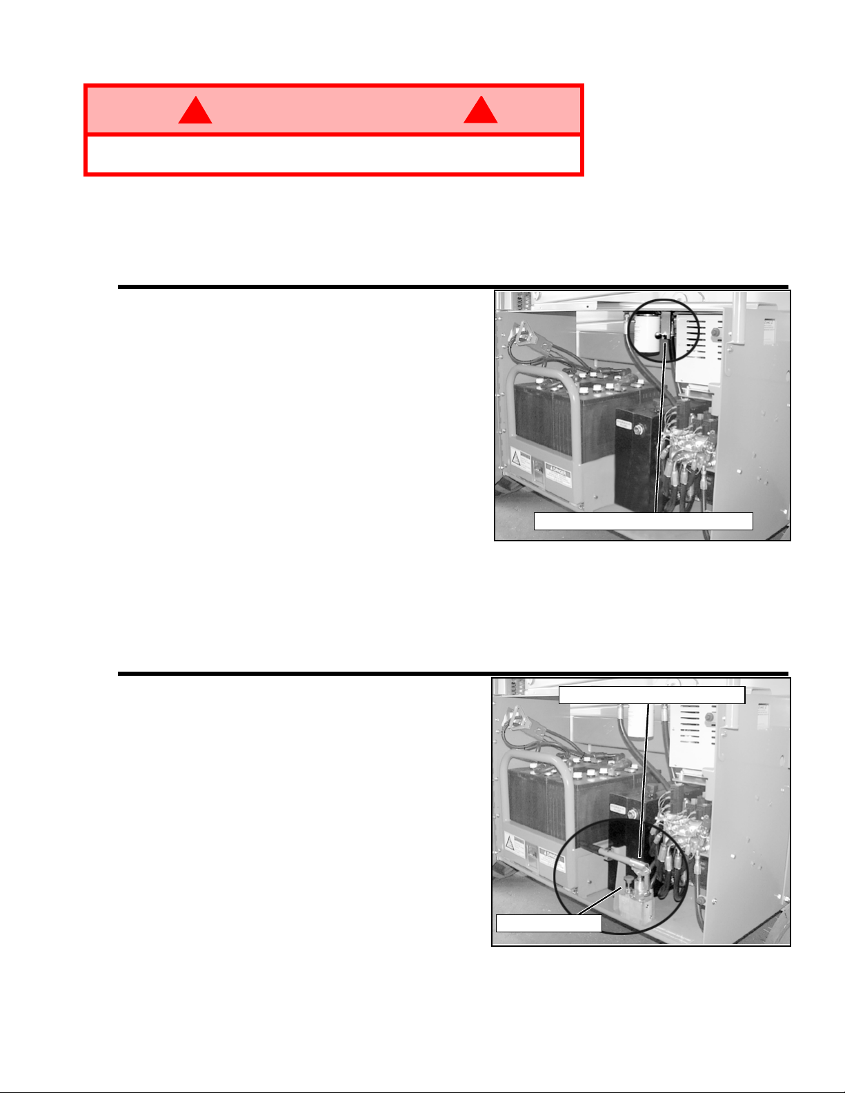
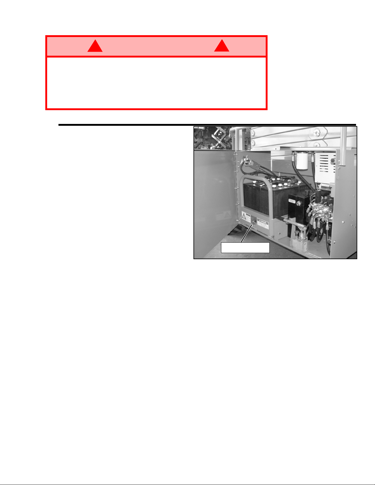
MERGENCY LOWERING
EMERGENCY LOWERING VALVE KNOB
EMERGENCY LOWERING VALVE
CONTROL VALVE
E
!
WARNING
If the platform should fail to lower,
assembly.
XRT27E
The Emergency Lowering Valve Knob is
located in the Power Module, above the
hydraulic oil tank.
1. Open the Power Module Cover.
2. Open the Emergency Lowering Valve by
pulling and holding the knob.
3. Once the platform is completely lowered,
release the knob to close the valve.
platform will not elevate if the Emergency Lowering Valve is open.
4. Close and secure the Power Module cover.
NEVER
!
climb down the elevating
Figure 5:
The
Emergency Lowering Valve Knob, XRT27E
XRT33E
The Emergency Lowering Valve is located in
the Power Module, next to the hydraulic oil
tank.
1. Open the Power Module cover.
2. Hold the Control Valve in the closed position, then pump up pressure to release
holding valves on the cylinders.
3. Once the platform is fully lowered, release
the control valve to close the holding
valves.
the Emergency Lowering Valve is open.
4. Close and secure the Power Module cover.
The platform will not elevate if
Figure 6:
Emergency Lowering Valve Knob, XRT33E
8 XRT Electric
Page 9
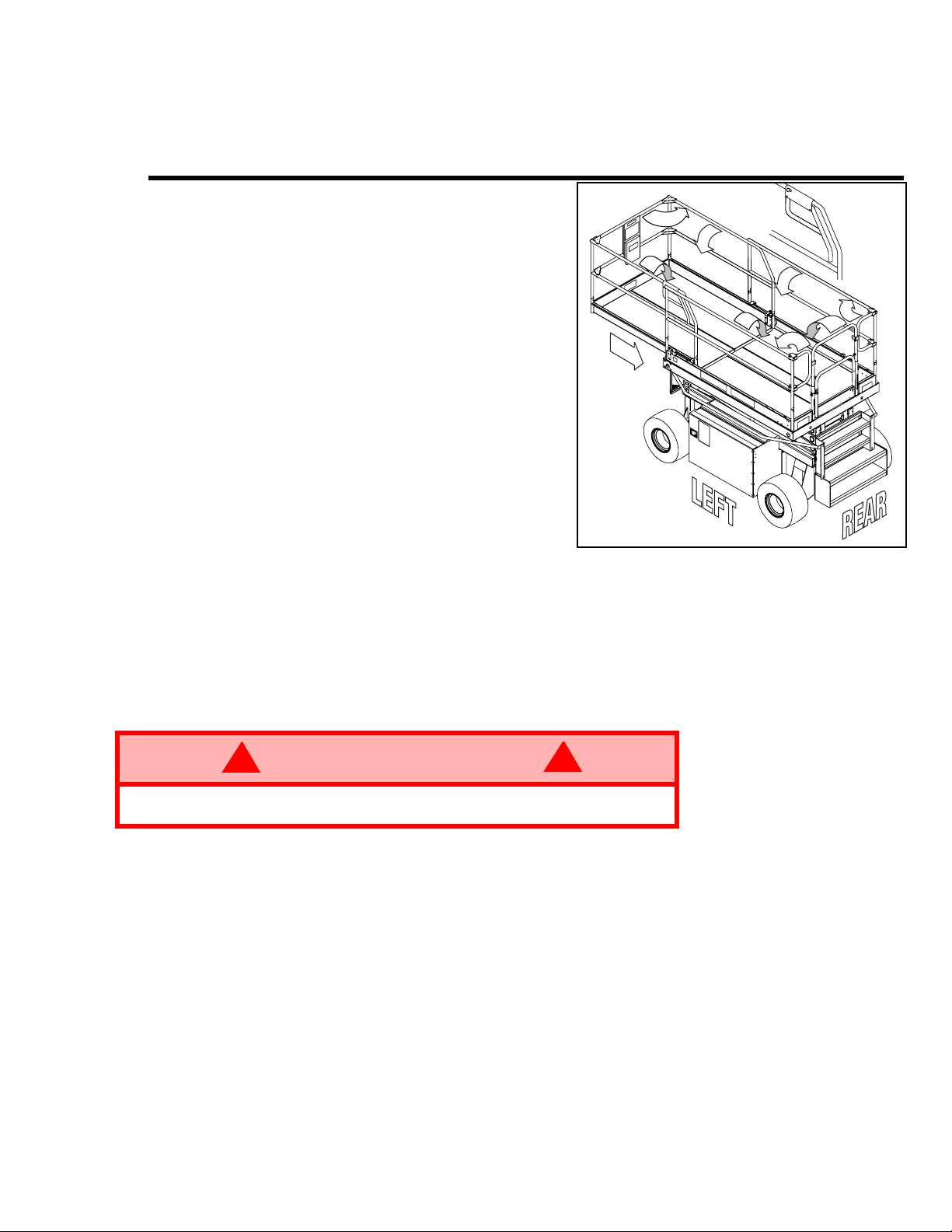
OLD DOWN GUARDRAILS
Deck
Extension
Handle
F
NOTE: When performing the following procedures, retain all fasteners.
This procedure is only for passing through doorways. Guardrails must be returned to proper position before using the machine.
F
OLD DOWN PROCEDURE
1. Ensure that the slide-out deck extension is
fully retracted and deck pin is locked. Place
the Platform Controls on the platform.
2. Pull the pins on the two end gate arms.
Lower the rear gate to the floor. Replace the
pins.
3. Pull the two pins on the left side of the front
rail and swing the front rail back against the
right handrail. Insert pins into the right
handrail.
4. Lift the right handrail up, then lower it to the
extension deck floor.
5. Push the deck extension handle into locked
position. Lift the left handrail up, then lower
it on top of the right handrail.
6. Rotate the arms in against the handrails.
7. Lift the right main handrail and lower it to
the floor.
8. Lift the left main handrail and lower it on top
of the right main hand rail.
Figure 7:
Fold Down Guardrails
E
RECTION PROCEDURE
1. Reverse the fold down procedure.
2. Hang the Platform Controls from front guardrail.
3. Before operating the work platform, check that all fasteners are in place and securely fastened.
!
WARNING
Before operating the machine, guardrails must be securely fastened in their
proper position.
• Rear bar may be raised to load material. Material may not be longer than the platform.
• Be sure gate is closed and bar is lowered before operating the machine.
!
9XRT Electric
Page 10
Electrocution Hazard
PLATFORM/CHASSIS/BRAKE
RELEASE SWITCH
BRAKE RELEASE BUTTON
Electrocution Hazard
Electrocution HazardElectrocution Hazard
THIS MACHINE IS
THIS MACHINE IS
THIS MACHINE IS THIS MACHINE IS
NOT INSULATED
NOT INSULATED
NOT INSULATEDNOT INSULATED
FTER USE EACH DAY
A
1. Ensure that the platform is fully lowered.
2. Park the machine on a firm, level surface, preferably under cover, secure against vandals, children and unauthorized operation.
3. Turn the key switch to OFF and remove the key to prevent unauthorized operation.
This machine is not insulated. Follow your national safety standards and maintain the
required safety distance when working near energized equipment.
ARKING BRAKE RELEASE
P
Perform the following only when the machine will not operate under its own power and it is necessary to move the machine or when winching onto a trailer to transport.
machine is on a slope. Hook machine to towing vehicle before releasing brakes.
Never release brakes if
1. Turn the Platform/Chassis/Brake Release switch to
BRAKE RELEASE. Alarm will sound.
2. Momentarily push BRAKE RELEASE button.
3. The machine will now roll when pushed or pulled.
4. Turn the Platform/Chassis/Brake Release switch to
PLATFORM or CHASSIS for normal parking brake
function.
!
WARNING
Never operate the work platform with the parking brakes released. Serious
injury or damage could result.
!
Figure 8:
Brake Release
10 XRT Electric
Page 11
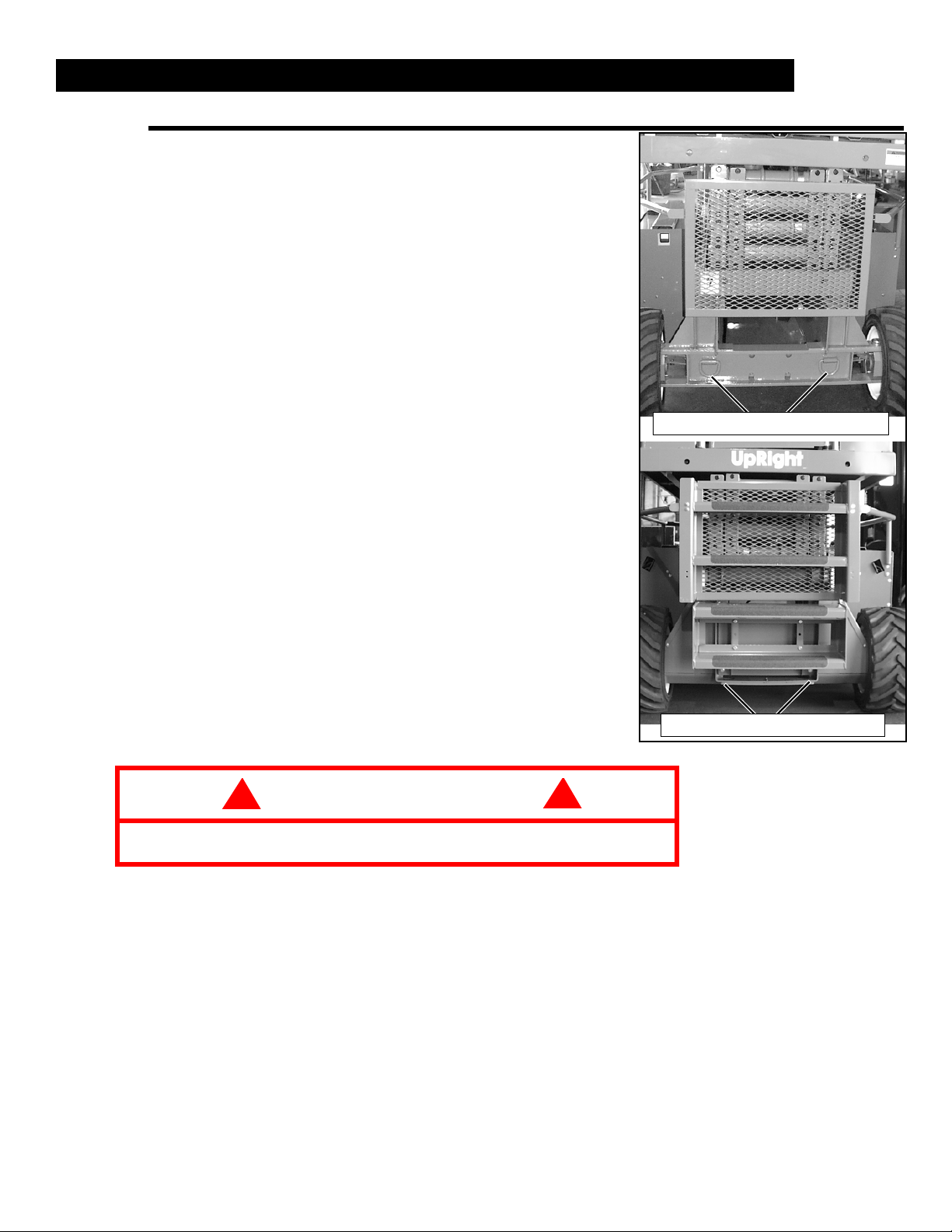
T
FRONT TIE DOWNS / LIFTING LUGS
REAR TIE DOWNS / LIFTING LUGS
RANSPORTING THE WORK PLATFORM
BY C
BY T
RANE
1. Secure straps to chassis Tie Downs/Lifting Lugs
only.
RUCK
1. Maneuver the work platform into transport position
and chock the wheels. The platform must be in the
fully lowered position for transport.
2. Secure the work platform to the transport vehicle
with chains or straps of adequate load capacity
attached to the front and rear Lift/Tie Down points on
both sides of the chassis.
Figure 9:
Transporting the Work Platform
Overtightening of chains or straps through Tie Down lugs may result in
damage to the work platform.
!
CAUTION
!
11XRT Electric
Page 12
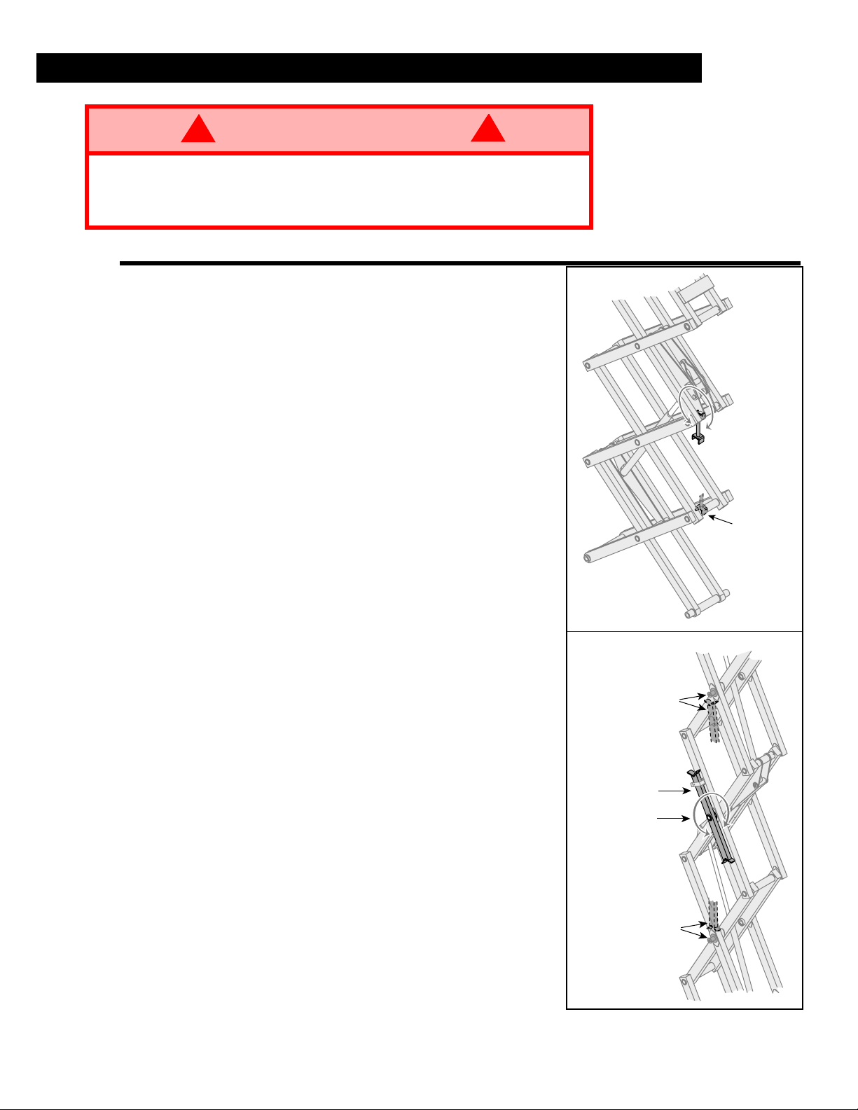
M
BRACE RESTS ON
WELDMENT WHEN IN
BLOCKING POSITION
ROTATE BRACE
CLOCKWISE
TO BLOCK
PIN RESTS ON
BRACE WHEN IN
BLOCKING POSITION
SCISSOR BRACE
IN REST POSITION
BRACE ROTATES
TO BLOCKING
POSITION
BRACE RESTS ON
PIN WHEN IN
BLOCKING POSITION
XRT27E
XRT33E
AINTENANCE
!
WARNING
Never perform service in the elevating assembly area while the platform is
elevated without first blocking the elevating assembly.
DO NOT
DO NOT
stand in elevating assembly area while deploying or storing brace.
block elevating assembly with a load on the platform.
UPPORTING THE ELEVATING ASSEMBLY
S
I
NSTALLATION
1. Park the work platform on a firm, level surface.
2. Pull the Chassis Emergency Stop Switch to the ON
position.
3. Pull the Platform Emergency Stop Switch to the ON
position.
4. Turn the Platform Controls Key Switch to ON.
5. Turn the Platform/Chassis switch to CHASSIS.
6. Push the RAISE button to elevate the platform until the
Scissor Brace can be rotated to the vertical position.
7. XRT27E – From the rear of the machine, lift the Scissor Brace from its stowed position. Rotate upward and
outward, then down until it is hanging vertically below
its attachment point.
8. XRT33E – From the left side of the machine, pull the
locking pin securing the brace. Rotate the Scissor
Brace counterclockwise until it is in the vertical position.
9. Lower the platform by pushing the Chassis Controls
LOWER button and gradually lower the platform until
the Scissor Brace is supporting the platform.
!
Figure 10:
Supporting the Elevating Assembly
R
12 XRT Electric
EMOVAL
1. Using the Chassis Controls, gradually raise the platform until the Scissor Brace is clear.
2. XRT27E – Rotate the Scissor Brace outward and
upward over its mounting point until it rests in the
stowed position.
3. XRT33E – Rotate the Scissor Brace clockwise until
the locking pin engages.
4. Lower the platform by pushing the Chassis Controls
LOWER button to completely lower the platform.
Page 13
ATTERY MAINTENANCE
B
!
WARNING
Hazard of explosive gas mixture. Keep sparks, flame and smoking materials
away from batteries.
Always wear safety glasses when working with batteries.
Battery fluid is highly corrosive. Thoroughly rinse away any spilled fluid with
clean water.
Always replace batteries with UpRight batteries or manufacturer approved
replacements.
• There are eight (8) batteries,
four (4) in each side module.
Open either module door to
gain access to a slide-out
battery tray containing four
batteries.
• Check battery fluid level daily,
especially if the work platform
is being used in a warm, dry
climate.
• If electrolyte level is lower
than 10 mm (3/8 in.) above
plates, add distilled water
only. DO NOT use tap water
with high mineral content. It
will shorten battery life.
• Keep terminals and tops of
batteries clean.
!
BATTERY TRAY
Figure 11:
Access to Batteries
13XRT Electric
Page 14
P
REVENTATIVE MAINTENANCE
The complete inspection consists of periodic visual and operational checks, along with periodic
minor adjustments to assure proper performance. Daily inspection will prevent abnormal wear
and prolong the life of all systems. The inspection and maintenance schedule is to be performed
at regular intervals. Inspection and maintenance shall be performed by personnel who are trained
and familiar with mechanical and electrical procedures.
!
WARNING
Before performing preventative maintenance, familiarize yourself with the
operation of the machine.
Always block the elevating assembly whenever it is necessary to enter the
scissor assembly to perform maintenance while the platform is elevated.
The preventative maintenance table has been designed for machine service and maintenance
repair. Please photocopy the following page and use the table as a checklist when inspecting the
machine for service.
ATE CODE IDENTIFICATION ON HOSES
D
ATES
G
uses a five digit code: Year, Month, Day.
!
i.e.: 6 11 29 - means 1996, month 11 (November), day 29.
ARKER
P
uses a ten digit code: Plant, Year, Month, Day.
i.e.: XXXX 6 11 29 - means Plant XXXX, 1996, month 11 (November), day 29.
AYCO
D
stamps month, day and year on each hose.
14 XRT Electric
Page 15
P
REVENTATIVE MAINTENANCE CHECKLIST
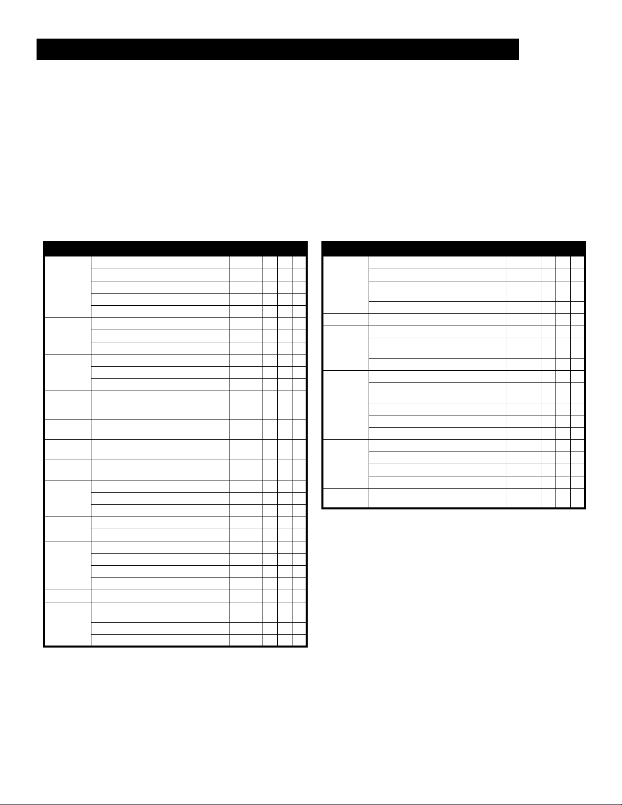
REVENTATIVE MAINTENANCE KEY
P
I
NTERVAL
Daily=each shift or every day
50h/30d=every 50 hours or 30 days
250h/6m=every 250 hours or 6 months
1000h/2y=every 1000 hours or 2 years
Y=Yes/Acceptable
N=No/Not Acceptable
R=Repaired/Acceptable
COMPONENT INSPECTION OR SERVICES INTERVAL Y N R
Check electrolyte level Daily
Check specific gravity 6m
Batteries
Hydraulic
Oil
Hydraulic
System
Emergency
Hydraulic
System
Chassis
Controls
Platform
Controls
Control
Cable
Platform
Deck and
Rails
Tires
Hydraulic
Pump
Drive Motors
Steering
System
Clean exterior 6m
Check battery cable condition Daily
Clean terminals 6m
Check oil level Daily
Change filter 6m
Drain and replace oil 2y
Check for leaks Daily
Check hose connections 30d
Check hoses for exterior wear 30d
Operate the emergency lowering valve
and check for serviceability
Check switch operation Daily
Check switch operation Daily
Check the exterior of the cable for
pinching, binding or wear
Check fasteners for proper torque Daily
Check welds for cracks Daily
Check condition of deck Daily
Check for damage Daily
Check lug nuts (torque to 90 ft. lbs.) 6m
Wipe clean 30d
Check for leaks at mating surfaces 30d
Check for hose fitting leaks Daily
Check mounting bolts for proper torque 6m
Check for operation Daily
Check hardware & fittings for proper
torque
Grease pivot pins 30d
Check steering cylinder for leaks 30d
Daily
6m
6m
REVENTATIVE MAINTENANCE REPORT
P
Date:________________________________________
Owner: ______________________________________
Model No:____________________________________
Serial No: ____________________________________
Serviced By: __________________________________
Service Interval: _______________________________
COMPONENT INSPECTION OR SERVICES INTERVAL Y N R
Inspect for structural cracks Daily
Elevating
Assembly
Tilt Sensor
Chassis
Lift Cylinder
Entire Unit
Labels
Check pivot points for wear 6m
Check mounting pin pivot bolts for proper
torque
Check elevating arms for bending 6m
Check for Operation 6m
Check hoses for pinch or rubbing points Daily
Check component mounting for proper
torque
Check welds for cracks Daily
Check the cylinder rod for wear 30d
Check mounting pin pivot bolts for proper
torque
Check seals for leaks 30d
Inspect pivot points for wear 6m
Check fittings for proper torque 6m
Check for and repair collision damage Daily
Check fasteners for proper torque 6m
Check for corrosion-remove and repaint 6m
Lubricate 30d
Check for peeling, missing, or unreadable
labels & replace
6m
6m
6m
Daily
15XRT Electric
Page 16

S
PECIFICATIONS
ITEM XRT27E XRT33E
Platform Size (Outside)
Standard 1,48 m x 2,34 m [58 in. x 92 in.] 1,48 m x 2,34 m [58 in. x 92 in.]
Slide Out Deck Extended 1,48 m x 3,33 m [58 in. x 131 in.] 1,48 m x 3,33 m [58 in. x 131 in.]
Max. Platform Capacity
Standard 567 kg [1250 lbs.] 454 kg [1000 lbs.]
on Extension 113 kg [250 lbs.] 113 kg [250 lbs.]
Max. No. of occupants
Total 4 people 3 people
on Extension 1 person 1 person
Height
Working Height 10,2 m [33 ft.] 12,1 m [39 ft.]
Max. Platform Height 8,2 m [27 ft.] 10,1 m [33 ft.]
Max. Drive Height 8,2 m [27 ft.] 10,1 m [33 ft.]
Dimensions
Weight, Standard 3250 kg [7160 lbs.] 3590 kg [7920 lbs.]
Overall Width 1,77 m [69,5 in.] 1,77 m [69.5 in.]
Overall Height (Rails Up) 2,57 m [101 in.] 2,72 m [107 in.]
Overall Height (Rails Folded) 1,83 m [72 in.] 1,96 m [77 in.]
Overall Length, Standard 2,69 m [106 in.] 2,69 m [106 in.]
Drive Speed
Platform Lowered 0 to 5,1 km/h [0 to 3,2 m.p.h.] 0 to 5,1 km/h [0 to 3,2 m.p.h.]
Platform Raised 0 to 0,8 km/h [0 to 0,5 m.p.h.] 0 to 0,8 km/h [0 to 0,5 m.p.h.]
Hydraulic Tank Capacity
Maximum Hydraulic System Pressure
Hydraulic Fluid
Normal use: Above 0° C [32° F] ISO #46 ISO #46
Low Temp. use: Below 0° C [32° F] ISO #32 ISO #32
Below -17° C [0° F] ISO #15 ISO #15
Lift System
Lift Speed
System Voltage
Power Source
Drive Control
Drive Motors
Tires
Standard G78-15 10 Ply Poly Filled G78-15 10 Ply Poly Filled
Optional Rough Terain 26-12-390 Poly Filled Lug 26-12-390 Poly Filled Lug
Optional Solid Non-Marking 17,8 cm X 30,5 cm [7 in. X 12 in.] 17,8 cm X 30,5 cm [7 in. X 12 in.]
Parking Brakes
Turning Radius (inside)
Maximum Gradeability
Ground Clearance
Wheel Base
Guardrails
Toeboard
Sound Level
Eight 6 volt 220 A Batteries (350 A option available) Eight 6 volt 220 A Batteries (350 A option available)
One Hand Proportional – Sevcon MOS90 One Hand Proportional – Sevcon MOS90
Dual, Spring Applied Hydraulic Release, Multiple Disc Dual, Spring Applied Hydraulic Release, Multiple Disc
1,1 m [44 in.] high, Fold Down with gate. 1,1 m [44 in.] high, Fold Down with gate.
23 l [6 US Gallons] 23 l [6 US Gallons]
172 bar [2500 psi] 172 bar [2500 psi]
One Single Stage Lift Cylinder Two Single Stage Lift Cylinders
Raise, 40 sec./Lower, 34 sec. Raise, 39 sec./Lower, 31 sec.
48 Volt DC 48 Volt DC
48 Volt DC Series Wound 48 Volt DC Series Wound
1,7 m [67 in.] 1,7 m [67 in.]
21,9° [40%] 19,2° [35%]
178 mm [7 in] 178 mm [7 in.]
2 m [78.38 in.] 2 m [78.38 in.]
152 mm [6 in.] High 152 mm [6 in.] High
76 dB 76 dB
Specifications are subject to change without notice. Hot weather or heavy use may reduce performance.
Meets or exceeds all applicable CE and GS Machinery Directive Requirements.
16 XRT Electric
Page 17
Section française
Section française
Section françaiseSection française
Consignes de sécurité
Risque d’électrocution
Risque d’électrocution Risque de basculement
Risque d’électrocutionRisque d’électrocution
Risque de basculement Risque de collision
Risque de basculementRisque de basculement
Risque de collision Risque de chute
Risque de collisionRisque de collision
Risque de chute
Risque de chuteRisque de chute
CETTE MACHINE
CETTE MACHINE
CETTE MACHINE CETTE MACHINE
N’EST PAS ISOLÉE.
N’EST PAS ISOLÉE.
N’EST PAS ISOLÉE.N’EST PAS ISOLÉE.
USAGE DE LA PLATE-FORME ÉLÉVATR IC E :
lage et des matériaux utilisés sur le chantier. Elle est conçue pour les travaux de réparations et d’assemblage sur les points élevés
(plafonds, grues, charpentes de toit, immeubles, etc.). Tout autre usage de la plate-forme élévatrice
CETTE PLATE-FORME ÉLÉVATRICE N’EST PAS ISOLÉE!
équipements électriques sous tension !
Il est interdit
Il est interdit
NE JAMAIS
RÉPA RT I R
NE JAMAIS
tions, bosses, trottoirs ou débris; et les éviter.
N’utiliser la machine
NE JAMAIS
EN CAS D’URGENCE,
Il est interdit
une structure préfabriquée etc. !
Il est interdit
verrouillé !
Il est interdit
élevée !
Il est interdit
similaires !
NE JAMAIS
dispositif d’élévation.
INSPECTER
fuites hydrauliques, de branchements électriques desserrés ou de câbles et flexibles endommagés avant d’utiliser la machine.
VÉRIFIER
NE JAMAIS
ou endommagés.
SI L’ALARME RETENTIT
machine jusqu’à une surface plane et ferme.
Il est interdit
celles se trouvant dans la zone de travail.
NE JAMAIS
l’hydrogène, un gaz explosif.
Sauf autorisation de la part d’UpRight, toute modification de la plate-forme
APRÈS AVOIR UTILISÉ
d’empêcher l’utilisation non autorisée de la plate-forme.
de dépasser la charge maximum admissible !
XRT27E 567 kg (1250 lb) pour quatre (4) personnes
XRT33E 454 kg (1000 lb) pour trois (3) personnes
d’utiliser la plate-forme comme appareil de levage ou grue (levage des charges par le dessous ou le dessus) !
dépasser 400 N (90 lb) de force latérale.
uniformément toutes les charges placées sur la plate-forme.
utiliser la machine sans avoir d’abord vérifié si la zone de travail est exempte de dangers tels que des trous, dénivella-
que sur des surfaces pouvant supporter la charge des roues.
utiliser la machine lorsque le vent souffle à plus de 45 km/h (28 mi/h) [12,5 m/s = 6 sur l’échelle de Beaufort].
appuyer sur le bouton d’arrêt d’urgence (EMERGENCY STOP) pour désactiver toutes les fonctions.
de monter ou de se tenir sur les garde-corps de la plate-forme et de passer de la plate-forme à un immeuble,
de retirer le portillon pivotant ou toute autre pièce de garde-corps ! Toujours vérifier que le portillon est fermé et
de maintenir le portillon pivotant en position ouverte (par exemple au moyen d’attaches) lorsque la plate-forme est
d’accroître la hauteur ou la portée de la plate-forme au moyen d’échelles, échafaudages ou autres dispositifs
effectuer de travaux d’entretien sur la machine, si la plate-forme est en position élevée, sans tout d’abord bloquer le
minutieusement la machine en vue de soudures fissurées, de pièces de boulonnerie manquantes ou desserrées, de
que tous les autocollants sont en place et lisibles avant d’utiliser la machine.
utiliser une machine qui est endommagée, qui ne fonctionne pas correctement ou dont les autocollants sont manquants
lorsque la plate-forme est élevée, ARRÊTER, abaisser la plate-forme avec précaution. Conduire la
de mettre tout dispositif de sécurité hors service, ce qui mettrait en danger les personnes à bord de la plate-forme et
charger les batteries à proximité d’étincelles ou d’une flamme vive. Lors de la charge, les batteries dégagent de
la plate-forme élévatrice, mettre les deux contacteurs à clé en position d’arrêt (OFF), puis retirer la clé afin
NE JAMAIS élever la plate-
forme ou conduire la machine
avec la plate-forme élevée si
elle n’est pas sur une surface
plate et ferme.
Cette plate-forme élévatrice est destinée au levage de toute personne, de son outil-
NE JAMAIS élever la plate-
forme avant de s’être assuré
de l’absence d’obstacles en
hauteur ou autres dangers.
C’est pourquoi il est impératif de rester à distance sûre des lignes et
est interdite
.
NE JAMAIS monter, ni se
tenir debout ou assis
sur les rampes du
garde-corps.
est interdit
!
Page 18
ARRÊT D’URGENCE
PLATE-FORME/CHÂSSIS/DESSERRAGE DE FREIN
LEVAGE
DESSERRAGE DE FREIN
ABAISSEMENT
I
NTRODUCTION
Ce manuel traite des plates-formes élévatrices électriques automotrices XRT. Cette machine fonctionne sur une batterie de 48 volts. Veiller à garder ce manuel sur la machine en tout temps.
I
NSPECTION DE SÉCURITÉ ET AVANT UTILISATION
Lire attentivement et veiller à bien comprendre et à respecter toutes les règles de sécurité, instructions
d’utilisation, et autocollants, ainsi que le MANUEL DES RESPONSABILITÉS de la Scaffold Industry
Association. Chaque jour avant d’utiliser la machine :
1. Ouvrir les panneaux des modules et s’assurer de l’absence de dommages, fuites d’huile ou pièces
manquantes.
2. Vérifier le niveau indiqué par la jauge du réservoir d’huile hydraulique avec la plate-forme complète-
ment abaissée. Ajouter de l’huile hydraulique si nécessaire.
3. Vérifier que le niveau de liquide de la batterie est correct (voir Entretien des batteries à la page 28).
4. Vérifier que tous les garde-corps sont en place et que tous les éléments de fixation sont bien serrés.
5. Vérifier que l’extension rétractable de la plate-forme est bloquée avec l’axe.
6. Vérifier l’état des pneus.
7. Inspecter minutieusement la machine en vue de soudures fissurées, de pièces de boulonnerie
manquantes ou desserrées, de fuites hydrauliques, de câbles et flexibles endommagés, de
branchements électriques et boulons de roues desserrés, avant de l’utiliser.
8. Fermer et verrouiller les couvercles des modules.
9. Au besoin, déplacer la machine jusqu’à un endroit dégagé afin de pouvoir l’élever complètement.
10. Tirer le bouton d’arrêt d’urgence du châssis en position activée (ON).
11. Tirer le bouton d’arrêt d’urgence de la plate-forme en position activée (ON).
12. Tourner le commutateur à clé de la plateforme vers la droite jusqu’à la position de
marche (ON).
13. Utiliser les commandes du châssis pour les
étapes 14 à 20.
14. Tourner le sélecteur plate-forme/châssis/
desserrage des freins à la position châssis
(CHASSIS).
15. Appuyer sur le bouton de commandes du
châssis levage (RAISE) pour élever la plateforme jusqu’à pouvoir tourner la barre de
verrouillage en position verticale. Bloquer le
mécanisme d’élévation comme décrit à la
page 27.
16. Effectuer une inspection visuelle du dispositif d’élévation, du vérin d’élévation, des
câbles et des tuyaux, pour détecter tout
dommage ou fonctionnement irrégulier. Véri-
fier qu’aucune pièce n’est lâche ou manquante.
17. Retirer le blocage de ciseau comme décrit à la page 27.
18. Appuyer sur le bouton de commandes du châssis levage (RAISE) pour élever complètement la
plate-forme.
19. Abaisser partiellement la plate-forme au moyen du bouton d’abaissement (LOWER) du châssis
pour vérifier le fonctionnement de l’alarme sonore d’abaissement.
20. Appuyer sur le bouton d’arrêt d’urgence du châssis pour en vérifier le bon fonctionnement. Toutes
les fonctions de la machine doivent être désactivées. Tirer le bouton d’arrêt d’urgence pour
remettre la machine en service.
Figure 12 :
Commandes du châssis
18 XRT électrique
Page 19
21. Vérifier le fonctionnement du système d’abaisse-
XRT27E
XRT33E
VANNE D ’ABAISSEMENT D’URGENCE
VANNE DE COMMANDE
BOUTON DE VANNE
D’ABAISSEMENT D’URGENCE
ment d’urgence.
A.
XRT27E –
Le bouton de vanne d’abaissement
d’urgence se trouve dans le module d’entraînement, au-dessus du réservoir d’huile hydraulique.
a. Ouvrir le panneau du module d’entraînement.
b. Tirer et maintenir le bouton pour ouvrir la
vanne d’abaissement d’urgence.
c. Une fois la plate-forme abaissée à fond,
relâcher le bouton pour fermer la soupape. La
plate-forme ne peut pas être élevée si la
vanne d’abaissement d’urgence est
ouverte.
d. Fermer et assujettir le panneau du module
d’entraînement.
B.
XRT33E –
La vanne d’abaissement d’urgence se
trouve dans le module d’entraînement, à côté du
réservoir d’huile hydraulique.
a. Ouvrir le panneau du module d’entraînement.
b. Maintenir la vanne de commande en position
fermée et faire monter la pression pour ouvrir
les vannes de maintien des vérins.
c. Une fois la plate-forme complètement abais-
sée, relâcher la vanne de commande pour
fermer les vannes de maintien. La plate-
forme ne peut pas être élevée si la vanne
d’abaissement d’urgence est ouverte.
d. Fermer et assujettir le panneau du module
d’entraînement.
22. Mettre le sélecteur de plate-forme/châssis en position plate-forme (PLATFORM).
23. Vérifier que le parcours est exempt de tout obstacle
(personnes, objets, trous, dénivellations, bosses et
débris), que le terrain est plat et peut supporter la
charge des roues.
24. Monter sur la plate-forme et fermer correctement
l’entrée.
25. Utiliser les commandes de plate-forme pour les
étapes restantes.
Figure 13 :
Abaissement d’urgence
19XRT électrique
Page 20
LOW
BATTERY
MOTOR
TEMPERATURE
HIGH
SPEED
LOW
SPEED
LIFT
DRIVE
RAISE FWD.
LOWER
REV.
EMERGENCY
STOP
ARRÊT D’URGENCE
BOUTON DE SÛRETÉ
COMMUTATEUR DE DIRECTION
LEVIER DE COMMANDE
CONDUITE/LEVAGE
SÉLECTEUR DE
VITESSE
COMMUTATEUR
À CLÉ
Figure 14 :
26. Tourner le sélecteur de conduite/levage sur la
position conduite (DRIVE).
NOTA: Le sélecteur de gamme de vitesses
présente deux positions : haute vitesse
(HIGH SPEED) et basse vitesse (LOW
SPEED). Effectuer l’étape 27 pour chaque
gamme de vitesses.
27. Engager le bouton de sûreté et pousser lente-
ment le levier de commande EN AVANT et EN
ARRIÈRE pour vérifier le fonctionnement de la
commande de vitesse proportionnelle.
28. Pousser le bouton de commande de direction
à DROITE puis à GAUCHE pour vérifier la
commande de la direction.
29. Tourner le sélecteur de conduite/levage sur
levage (LIFT).
30. Engager le bouton de sûreté et pousser
doucement le levier de commande vers l’avant
pour vérifier le fonctionnement des commandes de relevage de la plate-forme. Élever
la plate-forme au maximum.
31. Tirer le levier de commande vers l’arrière. La
plate-forme doit descendre et une alarme
sonore d’abaissement doit retentir.
32. Abaisser complètement la plate-forme.
33. Appuyer sur le bouton d’arrêt d’urgence de la
plate-forme pour en vérifier le bon fonctionnement. Toutes les fonctions de la machine
doivent être désactivées. Tirer le bouton
d’arrêt d’urgence pour remettre la machine en
service.
34. Mettre le commutateur à clé des commandes
de la plate-forme en position d’arrêt (OFF).
35. Enfoncer le bouton d’arrêt d’urgence en position d’arrêt (OFF).
36. Descendre de la plate-forme.
37. Enfoncer le bouton d’arrêt d’urgence du châssis en position d’arrêt (OFF).
Commandes de la plate-forme
20 XRT électrique
Page 21
U
TILISATION
Avant d’utiliser la plate-forme élévatrice, s’assurer que les inspections de sécurité avant utilisation ont
été effectuées et que tous les problèmes éventuels ont été corrigés. Ne jamais utiliser une machine
endommagée ou qui ne fonctionne pas correctement. L’opérateur doit être dûment formé sur cette
machine et doit lire et veiller à bien comprendre et respecter ce guide et les règles nationales de
sécurité.
XTENSION DE LA PLATE-FORME
E
Extension de la plate-forme
1. Monter sur la plate-forme et fermer correctement
l’entrée.
2. Appuyer sur la pédale située à l’arrière de l’extension de plate-forme. Pousser l’extension de plateforme en avant jusqu’à ce que l’axe de sûreté
s’engage dans la butée avant.
3. Pour rétracter l’extension, appuyer sur la pédale et
tirer l’extension vers l’arrière de la machine jusqu’à
ce que l’axe s’engage dans la butée arrière.
ÉPLACEMENT AVEC LA PLATE-FORME
D
Figure 15 :
ABAISSÉE
1. Vérifier que le parcours est exempt de tout obstacle
(personnes, objets, trous, dénivellations, bosses et
débris), que le terrain est plat et peut supporter la
charge des roues.
2. Tourner le sélecteur plate-forme/châssis/desserrage de frein en position plate-forme (PLATFORM).
3. Tirer le bouton d’arrêt d’urgence du châssis en position activée (ON).
4. Monter sur la plate-forme et fermer correctement l’entrée.
5. Vérifier les dégagements au-dessus, au-dessous et sur les côtés de la plate-forme.
6. Tirer le bouton d’arrêt d’urgence de la plate-forme en position activée (ON).
7. Tourner le commutateur à clé des commandes de plate-forme en position de marche (ON).
8. Tourner le sélecteur de levage/conduite sur la position conduite (DRIVE).
9. Mettre le sélecteur de gamme de vitesse en position haute vitesse (HIGH SPEED).
10. Engager le bouton de sûreté et mettre le levier de commande en position de marche avant
(FORWARD) ou de marche arrière (REVERSE) selon le sens de marche désiré. La vitesse de la
machine varie en fonction de l’éloignement du levier de sa position centrale.
11. Pour la conduite sur sol horizontal, mettre le sélecteur de gamme de vitesse en position haute
vitesse (HIGH SPEED).
12. Pour la montée de côtes ou les manœuvres dans des endroits confinés, mettre le sélecteur de
gamme de vitesse en position de basse vitesse (LOW SPEED).
IRECTION
D
1. Tourner le sélecteur de levage/conduite sur la position conduite (DRIVE).
2. Engager le bouton de sûreté, pousser le commutateur de direction vers la GAUCHE ou la DROITE
pour orienter les roues dans le sens voulu. Pendant la manœuvre de la machine observer les
roues pour s’assurer qu’elles sont braquées dans la direction voulue.
NOTA: La direction n’est pas à centrage automatique. Les roues doivent être remises en
position droite à l’aide du bouton de commande de direction.
21XRT électrique
Page 22

LÉVATION DE LA PLATE-FORME
É
1. Choisir une surface plane et ferme.
2. Tourner le sélecteur de levage/conduite sur levage (LIFT).
3. Engager le bouton de sûreté et pousser le levier de commande vers l’avant.
4. Si la machine n’est pas de niveau, l’alarme d’inclinaison retentit et la plate-forme ne peut être ni
élevée, ni conduite. Si l’alarme d’inclinaison retentit, la plate-forme doit être abaissée et la
machine conduite jusqu’à une surface plane et ferme avant d’être de nouveau levée.
ÉPLACEMENT AVEC LA PLATE-FORME ÉLEVÉE
D
NOTA: La machine se déplace à vitesse réduite lorsque la plate-forme est élevée.
1. Vérifier que le parcours est exempt de tout obstacle (personnes, objets, trous, dénivellations,
bosses et débris), que le terrain est plat et peut supporter la charge des roues.
2. Vérifier les dégagements au-dessus, au-dessous et sur les côtés de la plate-forme.
3. Tourner le sélecteur de conduite/levage sur la position conduite (DRIVE).
4. Mettre le sélecteur de gamme de vitesse en position haute vitesse (HIGH SPEED).
5. Engager le bouton de sûreté et mettre le levier de commande en position de marche avant
(FORWARD) ou de marche arrière (REVERSE) selon le sens de marche désiré. La vitesse de la
machine varie en fonction de l’éloignement du levier de sa position centrale.
6. Si la machine n’est pas de niveau, l’alarme d’inclinaison retentit et la plate-forme ne peut être ni
élevée, ni conduite. Si l’alarme d’inclinaison retentit, la plate-forme doit être abaissée et la
machine conduite jusqu’à une surface plane et ferme avant d’être de nouveau levée.
BAISSEMENT DE LA PLATE-FORME
A
1. Tourner le sélecteur de levage/conduite sur levage (LIFT).
2. Engager le commutateur de sûreté et tirer le levier de commande en arrière pour abaisser
la plate-forme.
22 XRT électrique
Page 23

BAISSEMENT D’URGENCE
BOUTON DE VANNE D’ABAISSEMENT D’URGENCE
VANN E D ’ABAISSEMENT D’URGENCE
VANNE DE COMMANDE
A
!
AVERTISSEMENT
Si la plate-forme ne s’abaisse pas, ne tenter EN AUCUN CAS d’en descendre
par le système élévateur.
!
XRT27E
Figure 16 :
Le bouton de vanne d’abaissement d’urgence se
trouve dans le module d’entraînement, au-dessus du réservoir d’huile hydraulique.
1. Ouvrir le panneau du module d’entraînement.
2. Tirer et maintenir le bouton pour ouvrir la
vanne d’abaissement d’urgence.
3. Une fois la plate-forme abaissée à fond,
relâcher le bouton pour fermer la soupape.
La plate-forme ne peut pas être élevée si
la vanne d’abaissement d’urgence est
ouverte.
4. Fermer et assujettir le panneau du module
d’entraînement.
XRT33E
Figure 17 :
Bouton de vanne d’abaissement d’urgence, XRT27E
Bouton de vanne d’abaissement d’urgence, XRT33E
La vanne d’abaissement d’urgence se trouve
dans le module d’entraînement, à côté du réservoir d’huile hydraulique.
1. Ouvrir le panneau du module d’entraîne-
ment.
2. Maintenir la vanne de commande en position
fermée et faire monter la pression pour
ouvrir les vannes de maintien des vérins.
3. Une fois la plate-forme complètement abaissée, relâcher la vanne de commande pour
fermer les vannes de maintien. La plate-
forme ne peut pas être élevée si la vanne
d’abaissement d’urgence est ouverte.
4. Fermer et assujettir le panneau du module
d’entraînement.
23XRT électrique
Page 24

ARDE-CORPS RABATTABLES
G
NOTA: Garder toutes les pièces de fixation lorsque vous effectuez les procédures suivantes.
Cette procédure n’est valable que pour le passage entre des portes. Il faut remettre les garde-corps en
position correcte avant d’utiliser l’engin.
Figure 18 :
R
EPLI DES GARDE-CORPS
1. S’assurer que l’extension de plate-forme est
complètement rétractée et que son axe de verrouillage est engagé. Installer les commandes
de la plate-forme sur la plate-forme.
2. Retirer les axes des deux bras d’extrémité du
portillon arrière. Abaisser le portillon arrière au
sol. Remettre les axes en place.
3. Retirer les deux axes du côté gauche du
garde-corps avant et rabattre ce garde-corps
contre celui de droite. Insérer les axes dans le
garde-corps droit.
4. Soulever le garde-corps de droite puis l’abaisser sur le plancher de l’extension de plateforme.
5. Pousser le levier de l’extension en position de
verrouillage. Soulever le garde-corps de
gauche, puis l’abaisser sur le garde-corps de
droite.
6. Faire pivoter les bras vers l’intérieur, contre les
garde-corps.
7. Soulever le garde-corps principal de droite,
puis l’abaisser au plancher.
8. Soulever le garde-corps principal de gauche, puis l’abaisser sur le garde-corps principal de droite.
Garde-corps rabattables
P
ROCÉDURE DE MISE EN PLACE
1. Reprendre la procédure de rabattage à l’inverse.
2. Suspendre les commandes de la plate-forme au garde-corps avant.
3. Avant d’utiliser la plate-forme élévatrice, vérifier que toute la boulonnerie est bien en place.
!
AVERTISSEMENT
Avant d’utiliser la machine, les garde-corps doivent être fermement assujettis et
en position correcte.
• La barre arrière peut être relevée pour charger le matériel. Le matériel ne doit pas être plus long
que la plate-forme.
• S’assurer que le portillon est fermé et que la barre est abaissée avant d’utiliser la machine.
!
24 XRT électrique
Page 25

Risque
SÉLECTEUR PLATE-FORME/
CHÂSSIS/DESSERRAGE DE FREIN
BOUTON DE DESSERRAGE
DE FREIN
Risque
RisqueRisque
d’électrocution
d’électrocution
d’électrocutiond’électrocution
CETTE MACHINE
CETTE MACHINE
CETTE MACHINE CETTE MACHINE
N’EST PAS ISOLÉE.
N’EST PAS ISOLÉE.
N’EST PAS ISOLÉE.N’EST PAS ISOLÉE.
PRÈS UTILISATION, TOUS LES JOURS
A
1. Abaisser complètement la plate-forme.
2. Garer la machine sur une surface plane et ferme, de préférence couverte, à l’abri des vandales et
protégée des enfants et de toute utilisation non autorisée.
3. Tourner le commutateur à clé sur la position d’arrêt (OFF), puis retirer la clé afin d’empêcher l’utili-
sation non autorisée.
Cette machine n’est pas isolée. Se conformer aux normes de sécurité en vigueur et maintenir
la distance de sécurité requise lors du travail à proximité d’équipements sous tension.
ESSERRAGE DU FREIN DE STATIONNEMENT
D
N’effectuer les opérations suivantes que si la machine est immobilisée et qu’il est nécessaire de la
déplacer ou pour la hisser sur une remorque à l’aide d’un treuil, pour le transport. Ne jamais
desserrer les freins si la machine est sur une pente. Accrocher la machine au véhicule remorqueur avant de desserrer les freins.
1. Tourner le sélecteur plate-forme/châssis/desserrage de
frein sur desserrage de frein (BRAKE RELEASE). L’alarme
retentira.
2. Appuyer momentanément sur le bouton desserrage de
frein (BRAKE RELEASE).
3. L’engin va maintenant rouler lorsqu’on le pousse ou qu’on
le tire.
4. Tourner le sélecteur plate-forme/châssis/desserrage de
frein en position plate-forme (PLATFORM) ou en position
châssis (CHÂSSIS) pour assurer un fonctionnement normal du frein de stationnement.
!
AVERTISSEMENT
Ne jamais élever ou abaisser la plate-forme lorsque les freins de stationnement
sont desserrés, ce qui pourrait résulter en des dommages ou blessures graves.
!
Figure 19 :
Desserrage de frein
25XRT électrique
Page 26

T
ANNEAUX DE LEVAGE/
D’ARRIMAGE ARRIÈRE
ANNEAUX DE LEVAGE/
D’ARRIMAGE ARRIÈRE
RANSPORT DE LA PLATE-FORME ÉLÉVATRICE
GRUE
PAR
N’attacher les sangles que dans les anneaux d’arrim-
1.
age/levage.
CAMION
PAR
1. Manœuvrer la plate-forme élévatrice en position de
transport et bloquer les roues. La plate-forme doit être
complètement abaissée pour le transport.
2. Arrimer la plate-forme sur le véhicule de transport au
moyen de chaînes ou sangles d’une capacité de charge
suffisante, fixées aux points de levage/arrimage avant et
arrière, des deux côtés du châssis.
Figure 20 :
Transport de la plate-forme élévatrice
!
ATTENTION
Un serrage excessif des chaînes ou des sangles dans les anneaux d’arrimage
peut endommager la plate-forme élévatrice.
26 XRT électrique
!
Page 27

E
XRT27E
XRT33E
NTRETIEN
Ne jamais travailler sur le système d’élévation ou à sa proximité pendant que la
plate-forme est élevée, sans tout d’abord le bloquer.
NE PAS se tenir à proximité du système d’élévation pendant le déploiement ou le
repli de la barre de verrouillage.
NE PAS bloquer le système d’élévation lorsqu’une charge se trouve sur
la plate-forme.
!
AVERTISSEMENT
!
UPPORT DU SYSTÈME ÉLÉVATEUR
S
I
NSTALLATION
1. Garer la plate-forme élévatrice sur une surface plane et
ferme.
2. Tirer le bouton d’arrêt d’urgence du châssis en position
activée (ON).
3. Tirer le bouton d’arrêt d’urgence de la plate-forme en
position activée (ON).
4. Mettre le commutateur à clé de commande de la plateforme en position de marche (ON).
5. Régler le sélecteur de plate-forme/châssis à la position
châssis (CHASSIS).
6. Appuyer sur le bouton levage (RAISE) pour élever la
plate-forme jusqu’à ce que la barre de verrouillage
puisse être relevée en position verticale.
7.
XRT27E –
verrouillage de sa position de rangement. La faire pivoter vers le haut et l’extérieur, puis vers le bas de
manière à ce qu’elle pende verticalement au-dessous
de son point de fixation.
8.
XRT33E –
l’axe de verrouillage de la barre. Tourner la barre de
verrouillage vers la gauche jusqu’à ce qu’elle soit à la
verticale.
9. Utiliser le bouton d’abaissement (LOWER) des commandes du châssis pour abaisser progressivement la
plate-forme jusqu’à ce qu’elle soit soutenue par la barre
de verrouillage.
De l’arrière de la machine, relever la barre de
Du côté gauche de la machine, désengager
Figure 21 :
Support du système élévateur
R
ETRAIT
1. Au moyen des commandes du châssis, élever graduellement la plate-forme jusqu’à ce qu’elle ne repose plus sur
la barre de verrouillage.
2.
XRT27E –
haut, à la verticale au-dessus de son point de fixation,
en position de rangement.
3.
XRT33E –
jusqu’à ce que l’axe de verrouillage s’engage.
4. Abaisser complètement la plate-forme au moyen du
bouton d’abaissement (LOWER) des commandes du
châssis.
Faire pivoter la barre de verrouillage vers le
Tourner la barre de verrouillage vers la droite
27XRT électrique
Page 28

NTRETIEN DES BATTERIES
E
!
AVERTISSEMENT
Risque d’émanations gazeuses explosives. Tenir les batteries à l’écart de toute
source d’étincelles, flammes et articles de fumeur.
Ne jamais manipuler les batteries sans porter de lunettes de sécurité.
L’électrolyte (liquide de la batterie) est un liquide très corrosif. Enlever en rinçant
soigneusement à l’eau claire tout liquide renversé.
Toujours remplacer les batteries par des batteries UpRight ou d’un modèle agréé
par le constructeur.
!
• Il y a huit (8) batteries, quatre
(4) dans chaque module latéral.
Ouvrir une porte de module
pour accéder au plateau de batterie coulissant contenant quatre batteries.
• Vérifier le niveau d’électrolyte
quotidiennement surtout si la
plate-forme élévatrice est
utilisée en climat chaud et sec.
• Si le niveau d’électrolyte ne
recouvre pas les plaques de
batterie d’au moins 10 mm
(3/8 po), ajouter de l’eau
distillée seulement. NE PAS utiliser d’eau du robinet très cal-
caire. Cela réduirait la vie utile
des batteries.
• Garder les bornes et le dessus
de la batterie propres.
PLATEAU DE BATTERIE
Figure 22 :
Accès aux batteries
28 XRT électrique
Page 29

E
NTRETIENS PRÉVENTIFS
Une inspection complète comprend les examens visuels et contrôles de fonctionnement périodiques,
ainsi que tous les réglages nécessaires au bon fonctionnement. Les inspections visuelles quotidi-
ennes évitent une usure anormale et prolongent la vie utile de tous les systèmes. Les opérations prescrites dans les programmes d’inspection et d’entretien doivent être effectuées à intervalles réguliers.
Les inspections et entretiens doivent être effectuées par un personnel compétent et familiarisé avec
les procédures mécaniques et électriques.
!
AVERTISSEMENT
Avant tout entretien préventif, se familiariser avec le fonctionnement de la
machine.
Toujours bloquer le système élévateur s’il est nécessaire de se trouver dans la
zone du ciseau lorsque la plate-forme est élevée.
Le tableau d’entretien préventif est conçu pour les entretiens et réparations de la machine. Faire une
photocopie de la page suivante et utiliser les tableaux comme liste de contrôle lors des entretiens.
DENTIFICATION DE CODE DE DATE SUR LES FLEXIBLES
I
G
ATES
par exemple : 6 11 29 – signifie année 1996
P
ARKER
par exemple : XXXX 6 11 29 – signifie usine XXXX, année 1996
D
AYCO
!
utilisent un code à cinq chiffres : année, mois, jour.
, mois 11 (novembre), jour 29.
utilise un code à dix chiffres : usine, année, mois, jour.
, mois 11 (novembre), jour 29.
imprime le mois, le jour et l’année sur chaque flexible.
29XRT électrique
Page 30

L
ISTE DE CONTRÔLE DES ENTRETIENS PRÉVENTIFS
ÉGENDE DES ENTRETIENS PRÉVENTIFS
L
P
ÉRIODICITÉ
Quot. = Chaque quart de travail ou cahque jour
50h/30j = toutes les 50 heures ou tous les mois (30 jours)
250h/6m = toutes les 250 heures ou tous les 6 mois
1000h/2a = toutes les 1000 heures ou tous les 2 ans
O = Oui/Acceptable
N = Non/Non Acceptable
R = Réparé/Acceptable
ÉLÉMENT
COMPOSANT
Batteries
Huile
hydraulique
Circuit
hydraulique
Système
hydraulique
de secours
Commandes
du châssis
Commandes
de la plateforme
Câble de
commande
Pont et
garde-corps
de la
plate-forme
Pneus
Pompe
hydraulique
Moteurs
VÉRIFICATION OU ENTRETIEN À EFFECTUER PÉRIODICITÉ O N R
Vérifier le niveau d’électrolyte.
Vérifier la densité.
Nettoyer l’extérieur.
Vérifier l’état des câbles de batterie.
Nettoyer les bornes.
Vérifier le niveau de l’huile.
Changer le filtre.
Vidanger et remplacer l’huile.
Vérifier s’il y a des fuites.
Vérifier le branchement des tuyaux flexibles.
Vérifier l’usure extérieure des tuyaux
flexibles.
Faire fonctionner la vanne d’abaissement
d’urgence et vérifier son bon
fonctionnement.
Vérifier le fonctionnement de l’interrupteur.
Vérifier le fonctionnement de l’interrupteur.
Vérifier l’extérieur du câble et rechercher
tout pincement, pliure ou usure.
Vérifier le serrage des pièces de fixation.
Vérifier si les soudures sont fissurées.
Vérifier l’état du plancher.
Vérifier le bon état.
Vérifier les écrous d’étrier 123 N·m
(serrage à 90 pi-lb).
Bien essuyer.
Vérifier s’il y a des fuites aux surfaces de
contact.
Vérifier s’il y a des fuites aux raccords.
Vérifier le serrage des boulons de fixation.
Vérifier le fonctionnement.
Quot.
6m
6m
Quot.
6m
Quot.
6m
2a
Quot.
30j
30j
Quot.
Quot.
Quot.
6m
Quot.
Quot.
Quot.
Quot.
6m
30j
30j
Quot.
6m
Quot.
APPORT D’ENTRETIEN PRÉVENTIF
R
Date : _________________________________________
Propriétaire : ____________________________________
o
de modèle : __________________________________
N
o
de série : ____________________________________
N
Nom du technicien : ______________________________
Périodicité d’entretien : ____________________________
ÉLÉMENT
COMPOSANT
Système de
direction
Dispositif
d’élévation
Détecteur
d’inclinaison
Châssis
Vérin de
levage
Ensemble de
la machine
Autocollants
VÉRIFICATION OU ENTRETIEN À EFFECTUER PÉRIODICITÉ O N R
Vérifier le serrage du matériel et des
raccordements.
Graisser les axes de pivot.
Vérifier s’il y a des fuites au vérin de
direction.
Vérifier si la structure présente des fissures.
Vérifier l’usure des pièces aux points
d’articulation.
Vérifier le serrage des boulons du pivot de la
goupille de fixation.
Vérifier que les arbres d’élévation sont bien
droits.
Vérifier le fonctionnement.
Vérifier que les tuyaux flexibles ne sont pas
pincés et n’ont pas de point de frottement.
Vérifier le serrage des fixations des
composants.
Vérifier si les soudures sont fissurées.
Vérifier l’usure de la tige de vérin.
Vérifier le serrage des boulons du pivot de la
goupille de fixation.
Vérifier s’il y a des fuites aux joints.
Vérifier l’usure des pièces aux points
d’articulation.
Vérifier le serrage des raccords.
Contrôler tout dommage dû à une collision
et le réparer.
Vérifier le serrage des pièces de fixation.
Vérifier s’il y a signe de corrosion;
décaper et repeindre.
Lubrifier.
Vérifier que les autocllants ne sont pas
décollés, manquants ou illsibles. Remplacer
au besoin.
6m
30j
30j
Quot.
6m
6m
6m
6m
Quot.
6m
Quot.
30j
6m
30j
6m
6m
Quot.
6m
6m
30j
Quot.
30 XRT électrique
Page 31

F
ICHE TECHNIQUE
ARTICLE XRT27E XRT33E
Dimensions de la plate-forme
(extérieures)
Standard
Extension déployée
Capacité max. de la plate-forme
Standard
sur l’extension
Nombre max. de personnes
To ta l
sur l’extension
Hauteur
Hauteur de travail
Hauteur max. de la plate-forme
Hauteur max. de conduite
Dimensions
Poids, standard
Largeur hors tout
Hauteur hors tout (garde-corps relevés)
Hauteur hors tout (garde-corps repliés)
Longueur hors tout, standard
Vitesse de conduite
Plate-forme abaissée
Plate-forme élevée
Capacité du réservoir hydraulique
Pression max. du circuit hydraulique
Huile hydraulique
Usage normal : au-dessus 0° C [32° F]
Basse temp. : au-dessous 0° C [32° F]
Au-dessous -17° C [0° F]
Système de levage
Vitesse de levage
Tension du circuit électrique
Source d’énergie
Commande de déplacement
Moteurs
Pneus
Standard
Optionnels tout terrain
Optionnels lisse ne marquant pas
Frein de stationnement
Rayon de braquage (intérieur)
Niveau de pente maximum
Garde au sol
Empattement
Garde-corps
Plinthe
Niveau acoustique
Huit batteries de 6 V 220 A (option 350 A disponible) Huit batteries de 6 V 220 A (option 350 A disponible)
1,48 m x 2,34 m [58 po x 92 po] 1,48 m x 2,34 m [58 po x 92 po]
1,48 m x 3,33 m [58 po x 131 po] 1,48 m x 3,33 m [58 po x 131 po]
567 kg [1250 lb] 454 kg [1000 lb]
113 kg [250 lb] 113 kg [250 lb]
4 personnes 3 personnes
1 personne 1 personne
10,2 m [33 pi] 12,1 m [39 pi]
8,2 m [27 pi] 10,1 m [33 pi]
8,2 m [27 pi] 10,1 m [33 pi]
3250 kg [7160 lb] 3590 kg [7920 lb]
1,77 m [69,5 po] 1,77 m [69,5 po]
2,57 m [101 po] 2,72 m [107 po]
1,83 m [72 po] 1,96 m [77 po]
2,69 m [106 po] 2,69 m [106 po]
0 à 5,1 km/h [0 à 3,2 mi/h] 0 à 5,1 km/h [0 à 3,2 mi/h]
0 à 0,8 km/h [0 à 0,5 mi/h] 0 à 0,8 km/h [0 à 0,5 mi/h]
23 L [6 gal US] 23 L [6 gal US]
172 bar [2500 psi] 172 bar [2500 psi]
ISO no 46 ISO no 46
ISO no 32 ISO no 32
ISO no 15 ISO no 15
Un vérin d’élévation à un étage Deux vérins d’élévation à un étage
Levage, 40 s/abaissement, 34 s Levage, 39 s/abaissement, 31 s
48 V CC 48 V CC
Proportionnelle d’une main – Sevcon MOS90 Proportionnelle d’une main – Sevcon MOS90
Bobinage série 48 V CC Bobinage série 48 V CC
G78-15 10 plis remplis de mousse G78-15 10 plis remplis de mousse
26-12-390 à barrettes, remplis de mousse 26-12-390 à barrettes, remplis de mousse
17,8 cm x 30,5 cm [7 po x 12 po] 17,8 cm x 30,5 cm [7 po x 12 po]
Deux, multidisques, serrage par ressort,
desserrage hydraulique
Deux, multidisques, serrage par ressort,
desserrage hydraulique
1,7 m [67 po] 1,7 m [67 po]
21,9° [40 %] 19,2° [35 %]
178 mm [7 po] 178 mm [7 po]
2 m [78,38 po] 2 m [78,38 po]
1,1 m [44 po] de haut, rabattable avec portillon 1,1 m [44 po] de haut, rabattable avec portillon
152 mm [6 po] de haut 152 mm [6 po] de haut
76 dB 76 dB
Ces caractéristiques peuvent être changées sans préavis. Les performances peuvent être réduites par temps très chaud ou en
cas de service sévère.
Conforme ou supérieur aux directives pour engins CE et GS.
31XRT électrique
Page 32

Deutschsprachiger Teil
Deutschsprachiger Teil
Deutschsprachiger TeilDeutschsprachiger Teil
Gefahr der Tötung durch
Gefahr der Tötung durch
Gefahr der Tötung durch Gefahr der Tötung durch
Stromschlag
Stromschlag
StromschlagStromschlag
Sicherheitsregeln
Gehahr des Umkippens
Gehahr des Umkippens Kollisionsgefahr
Gehahr des UmkippensGehahr des Umkippens
Kollisionsgefahr Absturzgefahr
KollisionsgefahrKollisionsgefahr
Absturzgefahr
AbsturzgefahrAbsturzgefahr
DIESE MASCHINE IST
DIESE MASCHINE IST
DIESE MASCHINE IST DIESE MASCHINE IST
NICHT ISOLIERT.
NICHT ISOLIERT.
NICHT ISOLIERT.NICHT ISOLIERT.
VERWENDUNG DER HOCHARBEITSBÜHNE:
und des für die Arbeit benötigten Materials. Sie ist für die Ausführung von Reparatur- und Montagearbeiten an hochgelegenen Arbeitsplätzen (Decken, Kränen, Dachkonstruktionen, Gebäuden usw.) vorgesehen. Sämtliche andere Einsatzzwecke der Hocharbeitsbühne
sind verboten
DIE HOCHARBEITSBÜHNE IST NICHT ISOLIERT!
ktrischer Geräte einen Sicherheitsabstand einzuhalten!
Es ist verboten
Die Verwendung bzw. der Betrieb der Hocharbeitsbühne als Hebevorrichtung oder Kran (Heben oder Absenken von Lasten)
ist verboten!
NIEMALS
Alle Lasten stets gleichmäßig auf der Arbeitsbühne
Maschine
Unebenheiten, Rinnsteine und Schutt zu untersuchen und diese zu umgehen.
Maschine nur auf Standflächen
Maschine
Beaufort-Skala überschreitet.
BEI NOTFÄLLEN
Es ist verboten
Stahl- oder vorgefertigte Betonbauteile zu besteigen!
Der Abbau der Schwenktür oder anderer Teile des Geländers
geschlossen und sicher verriegelt ist!
Es ist verboten
Es ist verboten,
zu vergrößern!
An der Maschine
blockieren.
Maschine vor Benutzung gründlich auf gerissene Schweißnähte, lose oder fehlende Metallteile, Hydrauliklecks, lose Kabelan-
schlüsse und beschädigte Kabel oder Schläuche
Vor Benutzung
Maschine
sind oder fehlen.
FALLS
absenken. Maschine auf eine feste, waagerechte Standfläche bringen.
Die Außerkraftsetzung von Sicherheitseinrichtungen
befindlichen Personen eine Gefahr dar.
Batterie
Wasserstoffgas freigesetzt.
Modifikationen der Hocharbeitsbühne
Arbeitsbühne
Schlüssel abgezogen wird.
die Querkraft von 400 N (90 lbs.) pro Benutzer überschreiten.
NIEMALS
NIEMALS
NIEMALS
während des Hochfahrens der Arbeitsbühne ein
NIEMALS
NACH GEBRAUCH
!
, die zulässige Höchstbelastung zu überschreiten.
XRT27E 567 kg (1250 lbs.)
XRT33E 454 kg (1000 lbs.)
in Betrieb nehmen, ohne zuvor das Arbeitsgelände auf Bodengefahren, wie z.B. Löcher, abschüssige Stellen,
in Betrieb nehmen, wenn die Windgeschwindigkeit 45 km/h (28 mph = 12,5 m/s) oder Windstärke 6 nach
den Notausschalter (EMERGENCY STOP) drücken, um alle Antriebsfunktionen zu deaktivieren.
, das Geländer der Arbeitsbühne zu besteigen, auf diesem zu stehen oder von der Arbeitsbühne her Gebäude,
, die Schwenktür offen zu lassen (mit Befestigungsbändern offen zu halten), wenn die Arbeitsbühne angehoben wird!
die Höhe bzw. Reichweite der Arbeitsbühne durch Aufstellen von Leitern, Gerüsten oder ähnlichen Gegenständen
NIEMALS
SICHERSTELLEN
in Betrieb nehmen, wenn diese beschädigt ist, nicht einwandfrei funktioniert oder deren Schilder beschädigt
in der Nähe von Funken oder bei offener Flamme aufladen. Beim Laden von Batterien wird explosives
NIEMALS
ausfahren oder die Maschine
mit ausgefahrener Arbeitsbühne
fahren, wenn der Boden nicht
in betrieb nehmen
Wartungsarbeiten durchführen, wenn die Arbeitsbühne hochgefahren ist, ohne das Hubgestell zu
, dass alle Schilder angebracht und gut lesbar sind.
sind verboten
vor unbefugter Benutzung sichern, indem beide Schlüsselschalter ausgeschaltet werden und der
die Arbeitsbühne
fest und eben ist.
Diese Hocharbeitsbühne dient zum Heben von Personen sowie deren Werkzeugen
Aus diesem Grund ist es dringend erforderlich, von stromführenden Teilen ele-
mit vier (4) Personen
mit drei (3) Personen
VERTEILEN
, die die Radlasten aufnehmen können.
ist verboten!
ÜBERPRÜFEN
WARNSIGNAL ERTÖNT
ist verboten
bzw. nur mit Genehmigung von UpRight zulässig.
Arbeitsbühne
Stellung fahren, ohne vorher
sicherzustellen, dass oberhalb der
Maschine keine Hindernisse oder
sonstige Gefahren bestehen.
.
Es ist immer zu kontrollieren, ob die Schwenktür
.
und stellt für die auf der Hocharbeitsbühne und in ihrer Reichweite
NIEMALS
, sofort STOPPEN und die Arbeitsbühne vorsichtig
in
NIEMALS
Schutzgeländer oder
dessen mittlere Schiene
steigen, darauf stehen
oder sitzen.
auf das
Page 33

E
NOTAUSSCHALTER
ARBEITSBÜHNE/FAHRWERK/BREMSENFREIGABE
ANHEBEN
BREMSENFREIGABE
ABSENKEN
INLEITUNG
Dieses Handbuch beschreibt die elektrische Arbeitsbühne XRT mit Eigenantrieb. Diese Maschine
arbeitet mit einer Bordspannung von 48 Volt. Dieses Handbuch muss ständig an der Maschine
aufbewahrt werden.
S
ICHERHEITSINSPEKTION VOR INBETRIEBNAHME
Lesen, verstehen und befolgen Sie sorgfältig sämtliche Sicherheitsregeln, Betriebsanleitungen und
Aufkleber sowie das PFLICHTENHANDBUCH des Verbands der Gerüstbauer. Täglich vor Inbetriebnahme die nachstehenden Schritte durchführen.
1. Moduldeckel öffnen und Einheit auf Beschädigung, Öllecks und fehlende Teile prüfen.
2. Hydraulikölstand am Schauglas des Hydrauliktanks bei völlig abgesenkter Arbeitsbühne prüfen.
Bei Bedarf Hydrauliköl nachfüllen.
3. Nachprüfen, ob der Batterieelektrolytstand stimmt (siehe „Batteriewartung“, Seite 43).
4. Nachprüfen, ob alle Schutzgeländer angebracht und alle Befestigungselemente vorschriftsmäßig
angebracht sind.
5. Kontrollieren, ob die herausziehbare Arbeitsbühnenverlängerung mit dem Stift gesichert ist.
6. Reifen auf Beschädigung prüfen.
7. Maschine gründlich auf gerissene Schweißnähte, lose oder fehlende Metallteile, Hydrauliklecks,
beschädigte Steuerkabel, lose Kabelanschlüsse und Radbolzen untersuchen.
8. Baugruppendeckel schließen und sichern.
9. Maschine, wenn erforderlich, an eine freie Stelle bringen, die das vollständige Hochfahren
ermöglicht.
10. Den Notausschalter des Fahrgestells in die Position „Ein“ (ON) ziehen.
11. Den Notausschalter der Arbeitsbühne in die Position „Ein“ (ON) ziehen.
12. Den Zündschlüssel zur Arbeitsbühnen-
steuerung nach rechts auf „Ein“ (ON)
drehen.
13. Für die Schritte 14 bis 20 die FahrwerkBedienelemente verwenden.
14. Den Schalter Arbeitsbühne/Fahrwerk/
Bremsenfreigabe auf „Fahrwerk“
(CHASSIS) stellen.
15. Mit dem Schalter „Anheben“ (RAISE) der
Fahrwerk-Bedienung die Arbeitsbühne aus-
fahren, bis die Scherenstütze in die vertikale Position gedreht werden kann. Das
Hubgestell, wie auf Seite 42 beschrieben,
blockieren.
16. Hubgestell, Hubzylinder, Kabel und
Schläuche visuell auf Beschädigungen und
ruckhafte Bewegungen untersuchen. Gerät
auf fehlende oder lose Teile untersuchen.
17. Die Stützstrebe des Scherengestänges,
wie auf Seite 42 beschrieben, entfernen.
18. Mit dem Schalter „Anheben“ (RAISE) der Fahrwerk-Bedienung die Arbeitsbühne voll ausfahren.
19. Die Arbeitsbühne durch Betätigung des Schalters „Absenken“ (LOWER) an der Steuerung des
Fahrgestells teilweise absenken und die Funktion des akustischen Absenkalarms prüfen.
20. Mit dem Notausschalter des Fahrwerks die korrekte Funktion prüfen. Sämtliche Maschinenfunktionen müssen dann abgeschaltet sein. Den Knopf des Notausschalters herausziehen, um den
Ausgangszustand wieder herzustellen.
Abbildung 23:
Fahrwerk-Bedienelemente
33 XRT Elektrisch
Page 34

21. Die Notabsenkung auf einwandfreie Funktion prüfen.
XRT27E
XRT33E
NOTSENKVENTIL
STEUERVENTIL
NOTSENKVENTILKNOPF
A.
XRT27E –
Der Knopf des Notsenkventils befindet
sich im Hydraulikaggregat, über dem Hydrauliktank.
a. Deckel des Hydraulikaggregats öffnen.
b. Das Notsenkventil wird durch Herausziehen
und Festhalten des Knopfs geöffnet.
c. Ventil nach völligem Absenken der Arbeits-
bühne durch Loslassen des Knopfes
schließen. Die Arbeitsbühne fährt nicht aus,
wenn das Notsenkventil geöffnet ist.
d. Deckel des Hydraulikaggregats schließen und
verschrauben.
B.
XRT33E –
Das Notabsenkventil befindet sich im
Hydraulikaggregat, neben dem Hydraulikbehälter.
a. Den Deckel des Hydraulikaggregats öffnen.
b. Steuerventil geschlossen halten; dann durch
Pumpen den Druck für die Freigabe der
Halteventile an den Zylindern erhöhen.
c. Nachdem die Arbeitsbühne vollständig abge-
senkt ist, das Steuerventil freigeben, um die
Halteventile zu schließen. Die Arbeitsbühne
fährt nicht aus, wenn das Notsenkventil
geöffnet ist.
d. Den Deckel des Hydraulikaggregats schließen
und verschrauben.
22. Den Schalter Arbeitsbühne/Fahrwerk auf „Arbeits-
bühne“ (PLATFORM) stellen.
23. Nachprüfen, ob die Fahrstrecke eben und frei von
Personen, Hindernissen, Löchern und Abhängen ist
und die Radlasten aufnehmen kann.
24. Auf die Arbeitsbühne steigen und den Eingang ordnungsgemäß verschließen.
25. Die Arbeitsbühnebedienung für die übrigen Schritte
verwenden.
Abbildung 24:
Notsenkung
34 XRT Elektrisch
Page 35

LOW
BATTERY
MOTOR
TEMPERATURE
HIGH
SPEED
LOW
SPEED
LIFT
DRIVE
RAISE FWD.
LOWER
REV.
EMERGENCY
STOP
NOTAUSSCHALTER
SPERRSCHALTER
LENKSCHALTER
STEUERHEBEL
HEBEN/FAHREN
GESCHWINDIG-
KEITSSCHALTER
SCHLÜSSEL-
SCHALTER
Abbildung 25:
26. Den Schalter Heben/Fahren auf „Fahren“
(DRIVE) stellen.
HINWEIS:Der Drehzahl-Wahlschalter hat
zwei Stellungen: „Hohe Drehzahl“ (HIGH
SPEED) und „Niedrige Drehzahl“ (LOW
SPEED). Schritt 27 ist bei jeder Drehzahl
durchzuführen.
27. Den Verriegelungsschalter einlegen und den
Steuerhebel auf „Vorwärts“ (FORWARD) und
danach auf „Rückwärts“ (REVERSE) schieben, um die Drehzahlregelung zu kontrollieren.
28. Den Lenkschalter nach RECHTS, dann nach
LINKS drücken, um die Lenkfunktion zu
prüfen.
29. Den Schalter Heben/Fahren auf „Heben“
(LIFT) drehen.
30. Den Verriegelungsschalter einlegen und den
Steuerhebel nach vorn drücken, um die Funktion der Bedienelemente zum Anheben der
Arbeitsbühne zu kontrollieren. Arbeitsbühne
ganz ausfahren.
31. Steuerhebel zurückziehen. Die Arbeitsbühne
sollte sich senken und ein Senkalarm sollte
hörbar sein.
32. Arbeitsbühne völlig absenken.
33. Mit dem Notausschalter der Arbeitsbühne die
korrekte Funktion prüfen. Sämtliche
Maschinenfunktionen müssen dann abgeschaltet sein. Den Notausschalter der Arbeitsbühne herausziehen, um den
Ausgangszustand wieder herzustellen.
34. Den Zündschlüssel zur Steuerung der Arbeitsbühne auf „Aus“ (OFF) drehen.
35. Den Notausschalter der Arbeitsbühne in die
Stellung „Aus“ (OFF) drücken.
36. Die Arbeitsbühne verlassen.
37. Den Notausschalter des Fahrwerks in die Stellung „Aus“ (OFF) drücken.
Steuerpult der Arbeitsbühne
35 XRT Elektrisch
Page 36

B
ETRIEB
Vor Betrieb der Arbeitsbühne muss die Sicherheitsprüfung vor durchgeführt und alle Mängel beseitigt
sein. Eine Maschine mit Defekten oder Fehlfunktionen niemals in Betrieb nehmen. Der Bediener
muss eingehend mit dieser Maschine vertraut sein, das Bedienerhandbuch vollständig gelesen und
verstanden haben sowie dessen Anweisungen und die geltenden Sicherheitsvorschriften und Sicherheitsanforderungen einhalten.
RBEITSBÜHNENVERLÄNGERUNG
A
Abbildung 26:
1. Auf die Arbeitsbühne steigen und den Eingang ordnungsgemäß verschließen.
2. Auf den Fußhebel am hinteren Ende der Arbeitsbüh-
nenverlängerung treten. Die Arbeitsbühnenverlängerung ausfahren, bis der Stift am vorderen
Anschlag einrastet.
3. Um die Arbeitsbühnenverlängerung einzufahren,
den Fußhebel herunterdrücken und die Arbeitsbüh-
nenverlängerung nach hinten zur Maschine ziehen,
bis der Stift am hinteren Anschlag einrastet.
AHREN MIT GESENKTER ARBEITSBÜHNE
F
1. Nachprüfen, ob die Fahrstrecke eben und frei von
Personen, Hindernissen, Löchern und Abhängen ist
und die Radlasten aufnehmen kann.
2. Den Schalter Arbeitsbühne/Fahrwerk/Bremsen-
freigabe auf „Arbeitsbühne“ (PLATFORM) stellen.
3. Den Notausschalter des Fahrgestells in die Position „Ein“ (ON) ziehen.
4. Auf die Arbeitsbühne steigen und den Eingang ordnungsgemäß verschließen.
5. Prüfen Sie nach, ob oberhalb, unterhalb und seitlich der Arbeitsbühne ein Sicherheitsabstand
besteht.
6. Den Notausschalter der Arbeitsbühne in die Position „Ein“ (ON) ziehen.
7. Den Schlüsselschalter zur Arbeitsbühnebedienung in die Stellung „Ein“ (ON) bringen.
8. Den Schalter Heben/Fahren auf „Fahren“ (DRIVE) stellen.
9. Den Schalter zur Auswahl der Drehzahl auf „Hohe Drehzahl“ (HIGH SPEED) stellen.
10. Den Sperrschalter einrasten lassen und den Steuerhebel auf „Vorwärts“ (FORWARD) oder „Rück-
wärts“ (REVERSE) stellen, um in die gewünschte Richtung zu fahren. Die Geschwindigkeit der
Maschine ändert sich je nach Entfernung des Steuerhebels von der Mittelstellung.
11. Den Schalter zur Auswahl der Drehzahl auf „Hohe Drehzahl“ (HIGH SPEED) stellen, wenn auf
ebenem Boden gefahren werden kann.
12. Den Schalter zur Auswahl der Drehzahl auf „
chungen bzw. beengte Räume befahren werden.
Niedrige
Drehzahl“ (LOW SPEED) stellen, wenn Bös-
Arbeitsbühnenverlängerung
ENKEN
L
1. Den Schalter Heben/Fahren auf „Fahren“ (DRIVE) stellen.
2. Den Verriegelungsschalter herunterdrücken und den Schalter der Lenkung auf RECHTS oder
LINKS stellen, bis die Räder in der gewünschten Richtung stehen. Beim Manövrieren der Maschine
die Räder beobachten, um die korrekte Fahrtrichtung zu gewährleisten.
ANMERKUNG:Die Lenkung ist nicht selbstrückstellend. Die Räder müssen durch
Betätigen des Lenkschalters wieder in Geradeausstellung gebracht werden.
36 XRT Elektrisch
Page 37

USFAHREN DER ARBEITSBÜHNE
A
1. Eine feste, ebene Fläche suchen.
2. Den Schalter Heben/Fahren auf „Heben“ (LIFT) drehen.
3. Den Verriegelungsschalter einlegen und den Steuerhebel nach vorn drücken.
4. Falls die Maschine nicht waagerecht steht, ertönt die Kippwarnung, und die Maschine lässt sich
weder hochfahren, noch in anderer Weise bewegen. Falls die Kippwarnung ertönt, muss die
Arbeitsbühne abgesenkt und die Maschine an eine ebene Stelle mit festem Boden gefahren
werden, bevor die Arbeitsbühne wieder hochgefahren werden kann.
AHREN MIT AUSGEFAHRENER ARBEITSBÜHNE
F
ANMERKUNG:Bei ausgefahrener Arbeitsbühne fährt die Maschine mit reduzierter
Geschwindigkeit.
1. Nachprüfen, ob die Fahrstrecke eben und frei von Personen, Hindernissen, Löchern und Abhängen ist und die Radlasten aufnehmen kann.
2. Die Sicherheitsabstände oberhalb, unterhalb und seitlich der Arbeitsbühne kontrollieren.
3. Den Schalter Heben/Fahren auf „Fahren“ (DRIVE) stellen.
4. Den Schalter zur Auswahl der Drehzahl auf „Hohe Drehzahl“ (HIGH SPEED) stellen.
5. Den Sperrschalter einrasten lassen und den Steuerhebel auf „Vorwärts“ (FORWARD) oder „Rück-
wärts“ (REVERSE) stellen, um in die gewünschte Richtung zu fahren. Die Geschwindigkeit der
Maschine ändert sich je nach Entfernung des Steuerhebels von der Mittelstellung.
6. Falls die Maschine nicht waagerecht steht, ertönt die Kippwarnung, und die Maschine lässt sich
weder hochfahren noch in anderer Weise bewegen. Falls die Kippwarnung ertönt, muss die
Arbeitsbühne abgesenkt und die Maschine an eine ebene Stelle mit festem Boden gefahren
werden, bevor die Arbeitsbühne wieder hochgefahren werden kann.
BSENKEN DER ARBEITSBÜHNE
A
1. Den Schalter Heben/Fahren auf „Heben“ (LIFT) drehen.
2. Den Sperrschalter einrasten lassen und den Steuerhebel zurückziehen, um die Arbeitsbühne
abzusenken.
37 XRT Elektrisch
Page 38

OTSENKUNG
KNOPF DES NOTSENKVENTILS
NOTSENKVENTIL
STEUERVENTIL
N
!
WARNUNG
NIEMALS am Hubgestell herabklettern, falls sich die Arbeitsbühne nicht
absenken lässt.
!
XRT27E
Abbildung 27:
Der Knopf des Notsenkventils befindet sich im
Hydraulikaggregat, über dem Hydrauliktank.
1. Den Deckel des Hydraulikaggregats öffnen.
2. Das Notsenkventil wird durch Herausziehen
und Festhalten des Knopfs geöffnet.
3. Ventil nach völligem Absenken der Arbeitsbühne durch Loslassen des Knopfes
schließen. Die Arbeitsbühne fährt nicht
aus, wenn das Notsenkventil geöffnet ist.
4. Den Deckel des Hydraulikaggregats schließen
und verschrauben.
Knopf des Notsenkventils,
XRT27E
XRT33E
Das Notabsenkventil befindet sich im Hydraulikaggregat, neben dem Hydraulikbehälter.
1. Den Deckel des Hydraulikaggregats öffnen.
2. Steuerventil geschlossen halten; dann durch
Pumpen den Druck für die Freigabe der
Halteventile an den Zylindern erhöhen.
3. Nachdem die Arbeitsbühne vollständig abge-
senkt ist, das Steuerventil freigeben, um die
Halteventile zu schließen. Die Arbeitsbühne
fährt nicht aus, wenn das Notsenkventil
geöffnet ist.
4. Den Deckel des Hydraulikaggregats
schließen und verschrauben.
Abbildung 28:
Knopf des Notsenkventils, XRT33E
38 XRT Elektrisch
Page 39

MKLAPPEN DER SCHUTZGELÄNDER
U
ANMERKUNG:Zur Durchführung der nachstehenden Schritte sämtliche Befestigungen
erhalten.
Diese Maßnahme ist nur beim Fahren durch Durchgänge zulässig. Schutzgeländer müssen vor Ver-
wendung der Maschine wieder in die vorgeschriebene Position gebracht werden.
Abbildung 29:
U
MKLAPPEN
1. Darauf achten, dass die ausziehbare Deckverlängerung völlig eingefahren und der
Deckbolzen arretiert ist. Die Bedienelemente
der Arbeitsbühne auf der Arbeitsbühne plazieren.
2. Die Bolzen der beiden Endtürarme herausziehen. Hintere Tür auf den Boden klappen. Die
Bolzen wieder einsetzen.
3. Die zwei Bolzen auf der linken Seite des
Frontgitters herausziehen, und das Frontgitter gegen das rechte Geländer zurücksch-
wenken. Die Bolzen in das rechte Geländer
einsetzen.
4. Rechte Geländerstange anheben, dann auf
den Boden der Deckverlängerung herunterlassen.
5. Den Griff der Deckverlängerung in Sperrstellung bringen. Linke Geländerstange anheben,
dann auf die rechte Geländerstange herablassen.
6. Die Arme nach innen gegen die Geländer-
stangen schwenken.
7. Das rechte Hauptteil des Schutzgeländers anheben und auf den Boden herablassen.
8. Das linke Hauptteil des Schutzgeländers anheben und auf dem rechten Hauptteil des
Schutzgeländers ablegen.
Umklappen der Schutzgeländer
A
UFRICHTEN
1. Erfolgt in umgekehrter Reihenfolge wie das Umklappen.
2. Die Arbeitsbühnen-Bedienelemente vom Schutzgeländer herunternehmen.
3. Vor Inbetriebnahme der Arbeitsbühne kontrollieren, ob alle Befestigungen angebracht und sicher
befestigt sind.
!
WARNUNG
Vor Inbetriebnahme der Maschine müssen die Schutzgeländer in der
vorgeschriebenen Stellung sicher befestigt sein.
• Die hintere Stange kann zum Verladen von Material angehoben sein. Das Material darf nicht
länger sein als die Arbeitsbühne.
• Vor Inbetriebnahme der Maschine map das Tor muss geschlossen sein und die Stange
abgesenkt werden.
!
39 XRT Elektrisch
Page 40

Gefahr der Tötung
SCHALTER ARBEITSBÜHNE/
FAHRWERK/BREMSENFREIGABE
BREMSENFREIGABE-SCHALTER
Gefahr der Tötung
Gefahr der Tötung Gefahr der Tötung
durch Stromschlag
durch Stromschlag
durch Stromschlagdurch Stromschlag
DIESE MASCHINE IST
DIESE MASCHINE IST
DIESE MASCHINE IST DIESE MASCHINE IST
NICHT ISOLIERT.
NICHT ISOLIERT.
NICHT ISOLIERT.NICHT ISOLIERT.
ACH TÄGLICHEM GEBRAUCH
N
1. Sicherstellen, dass die Arbeitsbühne vollständig abgesenkt ist.
2. Die Maschine auf ebenem Boden abstellen, vorzugsweise überdacht, und gegen mutwillige Beschädigung, Eingriffe durch Kinder und gegen unbefugter Inbetriebnahme sichern.
3. Schlüsselschalter auf „Aus“ (OFF) drehen und Schlüssel abziehen, um eine unbefugte Inbetriebnahme zu verhindern.
Diese Maschine ist nicht isoliert. Die Sicherheitsregeln Ihres Landes müssen befolgt werden
und der Sicherheitsabstand, der für Arbeiten an unter Spannung stehenden Geräten vorgeschrieben ist, muss stets eingehalten werden.
REIGABE DER FESTSTELLBREMSE
F
Die folgenden Maßnahmen sind nur durchzuführen, wenn die Maschine nicht mit eigener Kraft fahren
kann, aber bewegt oder zum Transport mit einer Winde auf einen Anhänger gezogen werden muss.
Die Bremsen niemals lösen, wenn die Maschine auf einer Böschung steht. Maschine vor
Freigabe der Feststellbremse zum Abschleppen anhängen.
!
Arbeitsbühne niemals bei gelöster Feststellbremse in Betrieb nehmen. Schwere
Verletzungen oder Schäden können die Folge sein.
1. Den Schalter Arbeitsbühne/Fahrwerk/Bremsenfreigabe auf
„Bremsenfreigabe“ (BRAKE RELEASE) stellen. Es ertönt
ein Alarm.
2. Kurz den Schalter „Bremsenfreigabe“ (BRAKE RELEASE)
drücken.
3. Die Maschine lässt sich dann durch Drücken oder Ziehen
rollen.
4. Den Schalter Arbeitsbühne/Fahrwerk/Bremsenfreigabe auf
„Arbeitsbühen“ (PLATFORM) bzw. „Fahrwerk“ (CHASSIS)
stellen, um die Feststellbremse normal zu verwenden.
WARNUNG
!
Abbildung 30:
Bremsenfreigabe
40 XRT Elektrisch
Page 41

T
HINTERE BEFESTIGUNGSLASCHEN/
HUBÖSEN
HINTERE BEFESTIGUNGSLASCHEN/
HUBÖSEN
RANSPORT DER ARBEITSBÜHNE
URCH KRAN
D
Gurte nur an den Verankerungs- bzw. Hublaschen
1.
des Fahrwerks befestigen.
URCH LKW
D
1. Die Arbeitsbühne in Transportposition bringen und die
Räder durch Keile sichern. Die Arbeitsbühne muss für
die Fahrt vollständig abgesenkt sein.
2. Die Arbeitsbühne für den Transport auf dem Fahrzeug
mit Ketten oder Bändern von entsprechender Tragfähigkeit an den vorderen und hinteren Anschlagpunkten an beiden Seiten des Fahrwerks absichern.
Abbildung 31:
Transport der Arbeitsbühne
!
Ein Überspannen der durch die Befestigungslaschen hindurch geführten Ketten
oder Gurte kann zur Beschädigung der Arbeitsbühne führen.
VORSICHT
!
41 XRT Elektrisch
Page 42

W
XRT27E
XRT33E
ARTUNG
!
WARNUNG
Niemals Wartungsarbeiten an dem ausgefahrenen Hubgestell durchführen, wenn
die Arbeitsbühne ausgefahren, aber nicht blockiert ist.
NIEMALS im Bereich des Hubgestells stehen, während die Stützstrebe
eingesetzt oder verstaut wird.
Hubgestell NIEMALS blockieren, wenn die Arbeitsbühne belastet ist.
NTERSTÜTZUNG DER HEBEBÜHNE
U
E
INSETZEN
1. Arbeitsbühne auf festem, ebenem Boden parken.
2. Den Notausschalter des Fahrgestells in die Position „Ein“
(ON) ziehen.
3. Den Notausschalter der Arbeitsbühne in die Position
„Ein“ (ON) ziehen.
4. Den Zündschlüssel zur Steuerung der Arbeitsbühne auf
„Ein“ (ON) drehen.
5. Den Schalter Arbeitsbühne/Fahrwerk auf „Fahrwerk“
(CHASSIS) drehen.
6. Den Schalter „Anheben“ (RAISE) drücken, um die
Arbeitsbühne auszufahren, bis die Scherenstütze in die
vertikale Position gedreht werden kann.
7.
XRT27E –
Maschine aus ihrer Transportposition herausnehmen.
Zunächst nach oben und außen, dann nach unten
schwenken, bis sie an der Stelle, wo sie eingelegt
werden soll, senkrecht nach unten hängt.
8.
XRT33E –
linken Maschinenseite aus herausziehen. Die Scherenstütze nach links drehen, bis sie vertikal steht.
9. Die Arbeitsbühne durch Drücken des Schalters „Absenken“ (LOWER) an der Fahrwerksteuerung langsam
absenken, bis die Scherenstütze die Arbeitsbühne hält.
Die Scherenstütze an der Rückseite der
Sicherungsbolzen der Scherenstütze von der
!
Abbildung 32:
Stützen des Hubgestells
E
NTFERNEN
1. Mit der Fahrwerksteuerung die Arbeitsbühne langsam
anheben, bis die Scherenstütze freigegeben ist.
2.
XRT27E –
ihren Montagepunkt schwenken, bis sie sich in Transportstellung befindet.
3.
XRT33E –
der Sperrbolzen einrastet.
4. Die Arbeitsbühne durch Drücken des Schalters
„Absenken“ (LOWER) an der Fahrwerksteuerung
vollständig herunterfahren.
42 XRT Elektrisch
Scherenstütze nach außen und oben über
Scherenstütze nach rechts schwenken, bis
Page 43

ATTERIEWARTUNG
B
!
WARNUNG
Gefahr durch explosives Gasgemisch. Funken, Flammen und Tabakwaren sind
von den Batterien fernzuhalten.
Beim Umgang mit Batterien ist stets eine Schutzbrille zu tragen.
Batterieflüssigkeit ist stark ätzend. Jede ausgelaufene Flüssigkeit muss durch
gründliches Spülen mit sauberem Wasser entfernt werden.
Batterien stets durch UpRight-Batterien oder solche ersetzen, die vom Hersteller
genehmigt sind.
• Insgesamt sind acht (8) Batterien vorhanden, vier (4) in
jedem Seitenmodul. Eine der
Modulklappen öffnen, um
Zugang zu dem Batterieeinschub mit den vier Batterien
zu erhalten.
• Flüssigkeitsstand der Batterie
täglich kontrollieren, insbesondere, wenn die Arbeitsbühne in einem warmen,
trockenen Klima eingesetzt
wird.
• Steht das Elektrolytstand nur
noch 10 mm (3/8 Zoll) über
der Plattenoberkante, nur mit
destilliertem Wasser
auffüllen. KEIN Leitungswasser mit hohem Mineralgehalt verwenden. Dadurch
verkürzt sich die Batterielebensdauer.
• Batterieanschlüsse und
Oberflächen der Batterien sauber halten.
!
Abbildung 33:
BATTERIEFACH
Zugang zu den Batterien
43 XRT Elektrisch
Page 44

V
ORBEUGENDE WARTUNG
Zur vollständigen Durchsicht gehören regelmäßige visuelle und Funktionsprüfungen, sowie
regelmäßige kleineren Einstellungen, mit denen eine ordnungsgemäße Funktion gesichert wird. Eine
tägliche Prüfung vermeidet anormalen Verschleiß und verlängert die Lebensdauer aller Systeme. Und
Wartung müssen in regelmäßigen Abständen durchgeführt werden. Inspektion und Wartung dürfen
nur von Personen vorgenommen werden, die mit den elektrischen und mechanischen Vorgängen der
Maschine vetrant sind.
!
WARNUNG
Machen Sie sich vor Durchführung der vorbeugenden Wartung mit der
Bedienung der Maschine vertraut.
Das Hubgestell immer blockieren, wenn bei ausgefahrener Arbeitsbühne
innerhalb des Scherenmechanismus Wartungsarbeiten durchgeführt werden
müssen.
Die Checkliste zur vorbeugenden Wartung gilt für Wartungsarbeiten der Maschine. Die folgende Seite
kopieren und die Tabelle als Checkliste bei Überprüfung der Maschine verwenden.
DENTIFIKATIONSSCHLÜSSEL BEI SCHLÄUCHEN
I
ATES
G
P
D
verwendet einen fünfstelligen Zahlencode: Jahr, Monat, Tag.
z.B.: 6 11 29 – bedeutet 1996
ARKER
verwendet einen zehnstelligen Zahlencode: Werk, Jahr, Monat, Tag.
z.B.: XXXX 6 11 29 – bedeutete Werk XXXX, 1996
AYCO
stempelt Monat, Tag und Jahr auf jedem Schlauch auf.
, Monat 11 (November), Tag 29.
!
, Monat 11 (November), Tag 29.
44 XRT Elektrisch
Page 45

C
HECKLISTE FÜR DIE VORBEUGENDE WARTUNG
CHLÜSSEL FÜR DIE VORBEUGENDE
S
ARTUNG
W
Z
EITABSTÄNDE
Täglich = je Schicht oder täglich
50 Std/30 Tage = alle 50 Stunden oder 30 Tage
250 Std/6 Monate = alle 250 Stunden oder 6 Monate
1000 Std/2 Jahre = alle 1000 Stunden oder 2 Jahre
J = Ja/Akzeptabel
N = Nein/Nicht akzeptabel
R = Repariet/Akzeptabel
GEGENSTAND INSPEKTION ODER WARTUNG ZEITABSTAND J N R
Elektrolytstand prüfen Täglich
Spezifisches Gewicht prüfen 6 Monate
Batterie
Hydrauliköl
Hydrauliksystem
Hydraulisches
Notsystem
Steuerpult
des
Fahrwerks
Bedienelemente der
Arbeitsbühne
Steuerkabel
Arbeitsbühnendeck und
Geländer
Reifen
Hydraulikpumpe
Antriebsmotoren
Lenksystem
Äußerlich reinigen 6 Monate
Batteriekabelzustand prüfen Täglich
Batterieklemmen reinigen 6 Monate
Ölstand prüfen Täglich
Filter wechseln 6 Monate
Öl ablassen und ersetzen 2 Jahre
Auf Lecks prüfen Täglich
Schlauchanschlüsse prüfen 30 Tage
Schläuche auf äußerliche Abnutzung
prüfen
Notsenkventil betätigen und auf
Brauchbarkeit prüfen
Schalterfunktion prüfen Täglich
Schalterfunktion prüfen Täglich
Das Kabel auf äußerlichen Verschleiß,
Bandage oder Quetschstellen
kontrollieren.
Befestigungselemente auf richtiges
Anzugsmoment prüfen
Schweißstellen auf Risse prüfen Täglich
Deckzustand prüfen Täglich
Auf Schäden prüfen Täglich
Radmuttern prüfen (Anzugsmoment
123 N·m (90 ft. lbs.)
Sauberwischen 30 Tage
Anschlussflächen auf Lecks prüfen 30 Tage
Schlauchverbindungen auf Lecks prüfen Täglich
Befestigungsschrauben auf richtiges
Anzugsmoment prüfen
Funktion prüfen Täglich
Metallteile und Anschlüsse auf richtiges
Anzugsmoment prüfen
Lagerzapfen schmieren 30 Tage
Lenkzylinder auf Lecks kontrollieren 30 Tage
30 Tage
Täglich
6 Monate
Täglich
6 Monate
6 Monate
6 Monate
ARTUNGSPROTOKOLL
W
Datum: ________________________________________
Eigentümer: ____________________________________
Modell-Nr.: _____________________________________
Serien-Nr.:______________________________________
Gewartet von: ___________________________________
Wartungsabstände:_______________________________
GEGENSTAND INSPEKTION ODER WARTUNG ZEITABSTAND J N R
Gestell auf Risse prüfen Täglich
Hubgestell
Neigungssensor
Fahrwerk
Hubzylinder
Gesamteinheit
Schilder
Lagerstellen auf Verschleiß prüfen 6 Monate
Befestigungszapfen-Schwenkbolzen auf
richtiges Anzugsmoment prüfen
Hubarme auf Verbiegung prüfen 6 Monate
Funktion prüfen 6 Monate
Schläuche auf Klemmstellen oder auf
Scheuerstellen prüfen
Befestigung der Bauteile auf korrektes
Anzugsmoment prüfen
Schweißstellen auf Risse prüfen Täglich
Kolbenstange auf Verschleiß prüfen 30 Tage
Befestigungszapfen-Schwenkbolzen auf
richtiges Anzugsmoment prüfen
Dichtungen auf Lecks prüfen 30 Tage
Lagerstellen auf Verschleiß prüfen 6 Monate
Anschlüsse auf richtiges Anzugsmoment
prüfen
Kollisionsschäden prüfen und reparieren Täglich
Befestigungselemente auf richtiges
Anzugsmoment prüfen
Auf Roststellen untersuchen, ggf. diese
entfernen und Einheit neu lackieren
Schmieren 30 Tage
Schilder auf Abblättern, Fehlen oder
Lesbarkeit prüfen & ersetzen
6 Monate
Täglich
6 Monate
6 Monate
6 Monate
6 Monate
6 Monate
Täglich
45 XRT Elektrisch
Page 46

T
ECHNISCHE DATEN
GEGENSTAND XRT27E XRT33E
Arbeitsbühnenabmessungen (außen)
Standard 1,48 m x 2,34 m [58 in. x 92 in.] 1,48 m x 2,34 m [58 in. x 92 in.]
Ausziehdeck ausgezogen 1,48 m x 3,33 m [58 in. x 131 in.] 1,48 m x 3,33 m [58 in. x 131 in.]
Max. Arbeitsbühnen-Tragfähigkeit
Standard 567 kg [1250 lbs.] 454 kg [1000 lbs.]
Aug Verlängerung 113 kg [250 lbs.] 113 kg [250 lbs.]
Max. Personenzahl
Total 4 Personen 3 Personen
Aug Verlängerung 1 Person 1 Person
Höhe
Arbeitshöhe 10,2 m [33 ft.] 12,1 m [39 ft.]
Max. Arbeitsbühnenhöhe 8,2 m [27 ft.] 10,1 m [33 ft.]
Max. Fahrhöhe 8,2 m [27 ft.] 10,1 m [33 ft.]
Abmessungen
Gewicht, Standard 3250 kg [7160 lbs.] 3590 kg [7920 lbs.]
Gesamtbreite 1,77 m [69,5 in.] 1,77 m [69,5 in.]
Gesamthöhe (Geländer aufrecht) 2,57 m [101 in.] 2,72 m [107 in.]
Gesamthöhe (Geländer umgeklappt) 1,83 m [72 in.] 1,96 m [77 in.]
Gesamtlänge, Standard 2,69 m [106 in.] 2,69 m [106 in.]
Fahrgeschwindigkeit
Arbeitsbühne gesenkt 0 bis 5,1 km/h [0 bis 3,2 mph] 0 bis 5,1 km/h [0 bis 3,2 mph]
Arbeitsbühne gehoben 0 bis 0,8 km/h [0 bis 0,5 mph] 0 bis 0,8 km/h [0 bis 0,5 mph]
Füllmenge, Hydaruliktank
Max. Hydrauliksystemdruck
Hydraulikflüssigkeit
Normalbetrieb: über 0° C [32° F] ISO-Nr. 46 ISO-Nr. 46
Niedrige Temperatur. Verwendung
bei: unter 0° C [32° F]
Unter -17° C [0° F] ISO-Nr. 15 ISO-Nr. 15
Hubsystem
Hubgeschwindigkeit
Systemspannung
Antrieb
Fahrsteuerung
Antriebsmotor
Reifen
Standard Cordlage G78-15 10, ausgeschäumt Cordlage G78-15 10, ausgeschäumt
Optional für unebenes Gelände Profilstollen 26-12-390 ausgeschäumt Profilstollen 26-12-390 ausgeschäumt
Optional Vollreifen, ohne Profil 17,8 cm x 30,5 cm [7 in. x 12 in.] 17,8 cm x 30,5 cm [7 in. x 12 in.]
Feststellbremsen
Wendekreisradius (innen)
Maximale Steigfähigkeit
Bodenfreiheit
Radstand
Schutzgeländer
Fußleiste
Schalldruckpegel
Acht Batterien 6 V 220 A (350 A als Option) Acht Batterien 6 V 220 A (350 A als Option)
Einhand-Proportionalsteuerung – Sevcon MOS90 Einhand-Proportionalsteuerung – Sevcon MOS90
Zwei, federbetätigt, hydraulische Freigabe, Mehrscheiben Zwei, federbetätigt, hydraulische Freigabe, Mehrscheiben
Höhe 1,1 m (44 in.); umklappbar einschl. TürHöhe 1,1 m (44 in.); umklappbar einschl. Tür
23 L [6 US Gallonen] 23 L [6 US Gallonen]
172 bar [2500 psi] 172 bar [2500 psi]
ISO-Nr. 32 ISO-Nr. 32
Ein einstufiger Hubzylinder Zwei einstufige Hubzylinder
Heben 40 s/Absenken 34 s Heben 39 s/Absenken 31 s
48 V Gleichstrom 48 V Gleichstrom
Serie mit 48 V-Gleichstromwicklung Serie mit 48 V-Gleichstromwicklung
1,7 m [67 in.] 1,7 m [67 in.]
21,9° [40 %] 19,2° [35 %]
178 mm [7 in] 178 mm [7 in.]
2 m [78,38 in.] 2 m [78,38 in.]
Höhe 152 mm [6 in.] Höhe 152 mm [6 in.]
76 dB 76 dB
Änderung technischer Daten ohne vorgerige Mitteilung vorbehalten. An heißen Tagen bzw. bei starker Beanspruchung kann sich die Leistung verringern.
Entspricht oder übertrifft alle Forderungen der gültigen CE- und GS- Maschinenvorschriften.
46 XRT Elektrisch
Page 47

Versión en español
Versión en español
Versión en españolVersión en español
Normas de seguridad
Peligro de electrocución
Peligro de electrocución Peligro de vuelco
Peligro de electrocuciónPeligro de electrocución
Peligro de vuelco Peligro de colisión
Peligro de vuelcoPeligro de vuelco
Peligro de colisión Peligro de caída
Peligro de colisiónPeligro de colisión
Peligro de caída
Peligro de caídaPeligro de caída
ESTA MÁQUINA NO
ESTA MÁQUINA NO
ESTA MÁQUINA NO ESTA MÁQUINA NO
ESTÁ AISLADA.
ESTÁ AISLADA.
ESTÁ AISLADA.ESTÁ AISLADA.
USO DE LA PLATAFORMA DE TRABAJO AÉREO:
heramientas y el material utilizado para el trabajo. Está diseñada para trabajos de reparación y montaje y labores que requieren
trabajar a niveles elevados (techos, grúas, estructuras de techos, edificios, etc.). ¡Cualquier otro uso de la plataforma de trabajo
está prohibido
aéreo
¡ESTA PLATAFORMA DE TRABAJO AÉREO NO ESTÁ AISLADA!
segura de las partes del equipo con corriente eléctrica!
Está prohibido
¡
Está prohibido
¡
abajo hacia arriba o desde un punto superior a otro inferior)!
NUNCA
DISTRIBUIR
NUNCA
abultamientos, bordillos o desechos, para evitarlos.
Operar la máquina
NUNCA
EN CASO DE EMERGENCIA,
funciones que estén alimentadas.
Está prohibido
¡
de acero, hormigón, etc.!
Está prohibido
¡
puerta giratoria de acceso está cerrada y asegurada!
Está prohibido
¡
cuando la plataforma está elevada!
Está prohibido
¡
NUNCA
de elevación.
INSPECCIONAR
fugas hidráulicas, conexiones de cables sueltas, cables o mangueras dañadas.
VERIFICAR
NUNCA
SI SUENA LA ALARMA
máquina a una superficie firme y plana.
Está prohibido
aéreo y en su área de trabajo.
NUNCA
Está prohibido
DESPUÉS DE UTILIZARLA
y retirando la llave.
exceder 400 N (90 lbs.) de fuerza lateral.
uniformemente el peso sobre la plataforma.
utilizar la máquina sin examinar antes el área de trabajo en busca de peligros, tales como hoyos, bajadas escarpadas,
operar la unidad si la velocidad del viento excede los 45 km/h (28 millas/hora) (12,5 m/seg. = 6 en la escala Beaufort)
realizar servicios de mantenimiento en la máquina, mientras la plataforma se encuentre elevada, sin bloquear el conjunto
que todas las etiquetas son legibles y están en su lugar antes de utilizar la máquina.
usar una máquina dañada, que no funcione correctamente o cuando las etiquetas estén dañadas o hagan falta.
cargar las baterías cerca de chispas o llamas. Cargar las baterías emite gas hidrógeno explosivo.
!
superar la carga máxima autorizada sobre la plataforma!
XRT27E 567 kg (1250 lbs.) incluyendo a cuatro (4) personas
XRT33E 454 kg (1000 lbs.) incluyendo a tres (3) personas
el uso y manejo de la plataforma de trabajo aéreo como herramienta de izado o grúa (elevación de cargas de
sólo en superficies capaces de soportar la carga de las ruedas.
subirse o ponerse de pie en las barandillas de la plataforma, o pasar de la plataforma a un edificio o estructuras
desmontar la puerta giratoria de acceso u otros componentes de las barandillas! ¡Siempre asegurarse de que la
tener la puerta giratoria de acceso en posición abierta (detenida en posición abierta con correas de anclaje),
aumentar la altura o alcance colocando escaleras, andamios o dispositivos similares sobre la plataforma!
la máquina completamente antes de utilizarla en busca de soldaduras rajadas, tornillería suelta o que haga falta,
mientras está elevada la plataforma, DETENERSE y descender la plataforma lentamente. Mover la
ignorar cualquier equipo de seguridad, pues presenta un peligro para las personas en la plataforma de trabajo
realizar modificaciones a la plataforma de trabajo aéreo sin la expresa autorización de UpRight.
NUNCA
conducir la máquina mientras la
encuentre sobre una superficie
empujar el botón de parada de emergencia (EMERGENCY STOP) para desactivar todas las
, proteger la plataforma de trabajo del uso no autorizado, desconectando ambos interruptores de llave
elevar la plataforma ni
plataforma esté en posición
elevada, a no ser que se
firme y nivelada.
El objeto de esta plataforma de trabajo aéreo, es elevar personas, sus
NUNCA
sin comprobar antes si existen
¡Por ello es absolutamente necesario mantener una distancia
colocar la plataforma
obstáculos suspendidos u
otros peligros.
NUNCA
subirse, sentarse
o pararse sobre las
barandillas o raíles de
media altura de la
plataforma.
.
Page 48

I
PAR A DA D E
EMERGENCIA
LIBERACIÓN DE LA PLATAFORMA/CHASIS/FRENO
ELEVAR
LIBERACIÓN DEL FRENO
BAJAR
NTRODUCCIÓN
Este manual cubre y proporciona información relacionada con las plataformas eléctricas autoimpulsantes, modelo XRT. Esta máquina funciona con un sistema de batería de 48 voltios. Este manual
debe guardarse siempre en la máquina.
I
NSPECCIÓN DE SEGURIDAD PREVIA A LA OPERACIÓN
Lea con detenimiento, comprenda y respete todas las normas de seguridad, instrucciones operativas,
etiquetas y el MANUAL DE RESPONSABILIDADES de la Scaffold Industry Association. Llevar a cabo
lo siguiente, cada día, antes de utilizar la máquina.
1. Abrir las cubiertas del módulo e inspeccionar posibles daños, fugas de aceite o piezas que falten.
2. Comprobar el indicador del nivel de aceite hidráulico del depósito hidráulico con la plataforma totalmente bajada. Añadir aceite hidráulico si fuera necesario.
3. Comprobar que el nivel de líquido de las baterías es el correcto (ver “Mantenimiento de la batería”,
página 58).
4. Comprobar que todas las barandillas estén aseguradas en su lugar, con todos los pasadores apretados adecuadamente.
5. Comprobar que la extensión de la cubierta deslizante esté fijada con el pasador.
6. Comprobar que los neumáticos no presenten daños.
7. Inspeccionar la máquina completamente en busca de soldaduras agrietadas, tornillería suelta,
fugas hidráulicas, cable de control dañado, y que las conexiones de los cables y los tornillos de las
ruedas no estén flojos.
8. Cerrar y asegurar las cubiertas del módulo.
9. Desplazar la máquina, si fuera necesario, hasta una zona sin obstáculos en la que se permita una
elevación completa.
10. Tirar del interruptor de parada de emergencia del chasis a la posición encendido (ON).
11. Tirar del interruptor de parada de emergencia de la plataforma hacia la posición encendido (ON).
12. Girar el interruptor de llave de los controles
de la plataforma en el sentido horario hacia
la posición de encendido (ON).
13. Usar los controles del chasis para seguir las
instrucciones de los pasos del 14 al 20.
14. Girar el interruptor de la plataforma/chasis/
liberación del freno a chasis (CHASSIS).
15. Presionar el botón elevar (RAISE) de los
controles del chasis, para elevar la
plataforma hasta que el soporte de la armadura tipo tijera pueda rotarse hasta la
posición vertical. Bloquear el conjunto de
elevación como se describe en la
página 57.
16. Inspeccionar visualmente el conjunto de elevación, cilindro de elevación, cables y
mangueras por posibles daños o funcionamiento extraño. Comprobar por piezas sueltas o que hagan falta.
17. Retirar el soporte de la armadura tipo tijera como se describe en la página 57.
18. Presione el botón elevar (RAISE) de los controles del chasis para elevar la plataforma completamente.
19. Bajar parcialmente la plataforma, pulsando el botón bajar (LOWER) de los controles del chasis y
verificar el funcionamiento de la alarma de bajada.
20. Empujar el botón de parada de emergencia del chasis para comprobar su funcionamiento correcto.
Todas las funciones de la máquina deben desactivarse. Tirar hacia fuera del botón de parada de
emergencia para continuar.
Figura 34:
Controles del chasis
48 XRT eléctrica
Page 49

21. Comprobar que el sistema de bajada de emergencia
XRT27E
XRT33E
VÁLVULA DE BAJADA DE
EMERGENCIA
VÁLVULA DE CONTROL
PERILLA DE LA VÁLV U LA D E
BAJADA DE EMERGENCIA
funcione adecuadamente.
A.
XRT27E –
La perilla de la válvula de bajada de
emergencia está situada en el módulo de potencia, sobre el tanque de aceite hidráulico.
a. Abrir la tapa del módulo de potencia.
b. Abrir la válvula de bajada de emergencia
tirando y sujetando la perilla.
c. Cuando la plataforma esté totalmente abajo,
suelte la perilla para cerrar la válvula. La
plataforma no se elevará si la válvula de
bajada de emergencia está abierta.
d. Cerrar y asegurar la cubierta del módulo de
potencia.
B.
XRT33E –
La válvula de bajada de emergencia
está situada en el módulo de potencia, próxima
al depósito de aceite hidráulico.
a. Abrir la cubierta del módulo de potencia.
b. Mantener la válvula de control en la posición
de cerrado, luego bombear presión para liberar las válvulas de retención de los cilindros.
c. Cuando la plataforma esté totalmente abajo
libere la válvula de control para cerrar las
válvulas de retención. La plataforma no se
elevará si la válvula de bajada de emergencia está abierta.
d. Cerrar y asegurar la cubierta del módulo de
potencia.
22. Girar el interruptor plataforma/chasis a plataforma
(PLATFORM).
23. Comprobar que en el recorrido no haya obstáculos
(personas, obstrucciones, agujeros, bajadas escarpadas, abultamientos y desechos), que esté nivelado y que pueda soportar la carga de las ruedas.
24. Subir a la plataforma y cerrar la entrada debidamente.
25. Utilice los controles de la plataforma para llevar a
cabo los pasos siguientes.
Figura 35:
Bajada de emergencia
49XRT eléctrica
Page 50

LOW
BATTERY
MOTOR
TEMPERATURE
HIGH
SPEED
LOW
SPEED
LIFT
DRIVE
RAISE FWD.
LOWER
REV.
EMERGENCY
STOP
PARADA DE
EMERGENCIA
INTERRUPTOR DE
ENTRECLAVAMIENTO
INTERRUPTOR DE DIRECCIÓN
PALANCA DE CONTROL
ELEVAR/
CONDUCIR
SELECTOR DE
VELOCIDAD
INTERRUPTOR
DE LLAVE
Figura 36:
Controles de la plataforma
26. Girar el interruptor conducir/elevar a la posición
conducir (DRIVE).
NOTA:El interruptor de rango de
velocidad tiene dos posiciones:
velocidad alta (HIGH SPEED) y velocidad
baja (LOW SPEED). Realice el paso 27
para cada velocidad.
27. Activar el interruptor de entreclavamiento y
mover suavemente la palanca de control de
avance (FORWARD) y, a continuación, marcha
atrás (REVERSE), para comprobar el control
de la velocidad proporcional.
28. Empujar el interruptor de dirección a la DERECHA, luego a la IZQUIERDA para comprobar el
control de dirección.
29. Girar el interruptor elevar/conducir a elevar
(LIFT).
30. Activar el interruptor de entreclavamiento y pulsar la palanca de control hacia adelante, para
comprobar los controles de elevación de la
plataforma. Levantar la plataforma hasta su
máxima elevación.
31. Tirar hacia atrás de la palanca de control. La
plataforma deberá descender y la alarma audible de descenso deberá sonar.
32. Descender la plataforma completamente.
33. Empujar el botón de parada de emergencia de
la plataforma para comprobar su funcionamiento correcto. Todas las funciones de la
máquina deben desactivarse. Tirar hacia fuera
del botón de parada de emergencia de la
plataforma para continuar.
34. Girar el interruptor de llave de los controles de
la plataforma a la posición de apagado (OFF).
35. Empujar el botón de parada de emergencia de
la plataforma a la posición de apagado (OFF).
36. Desmontar la plataforma.
37. Empujar el botón de parada de emergencia del chasis a la posición de apagado (OFF).
50 XRT eléctrica
Page 51

F
UNCIONAMIENTO
Antes de hacer funcionar la plataforma de trabajo, asegurarse de que ha sido completada la inspección de seguridad previa a la operación y que cualquier deficiencia ha sido corregida. Nunca operar
una máquina dañada o con funcionamiento defectuoso. El operario debe haber recibido una
completa y adecuada formación para el uso de esta máquina, y ha de leer, comprender totalmente y
seguir las instrucciones que le ofrece este Manual del operario. El operario debe haber sido debidamente aleccionado sobre el functionamiento de esta máquina, y debe leer, entender completamente y
seguir este Manual del operario y la normativa/disposiciones locales en materia de seguridad personal.
XTENSIÓN DE LA PLATAFORMA
E
Extensión de la plataforma
1. Subir a la plataforma y cerrar la entrada
debidamente.
2. Pisar el pedal situado en la parte trasera de la
extensión de la plataforma. Empujar la extensión de
la plataforma hacia adelante hasta que el pasador
enganche en el tope delantero.
3. Para retraer la extensión de la plataforma, presionar
el pedal y tirar de la extensión de la plataforma
hacia la parte trasera de la máquina hasta que el
pasador enganche en el tope trasero.
ESPLAZAMIENTO CON LA PLATAFORMA
D
Figura 37:
EN POSICIÓN BAJA
1. Comprobar que en el recorrido no haya obstáculos
(personas, obstrucciones, agujeros, bajadas escarpadas, abultamientos y desechos), que esté nivelado y que pueda soportar la carga de las ruedas.
2. Girar el interruptor de plataforma/chasis/liberación
del freno a la posición plataforma (PLATFORM).
3. Tirar del interruptor de parada de emergencia del chasis a la posición encendido (ON).
4. Subir a la plataforma y cerrar la entrada debidamente.
5. Comprobar las distancias de seguridad por arriba, abajo y a los lados de la plataforma de trabajo.
6. Tirar del interruptor de parada de emergencia de la plataforma hacia la posición encendido (ON).
7. Girar el interruptor de llave de los controles de la plataforma a la posición encendido (ON).
8. Girar el interruptor elevar/conducir a la posición conducir (DRIVE).
9. Fijar el interruptor selector del rango de velocidad en la posición de velocidad alta (HIGH SPEED).
10. Accionar el interruptor de entreclavamiento y mover la palanca de control a la posición adelante
(FORWARD) o marcha atrás (REVERSE) para desplazarse en la dirección deseada. La velocidad
de la máquina variará dependiendo de la distancia que se mueva el control de mando de la
posición central.
11. Girar el intreruptor selector del rango de velocidad a la posición de velocidad alta (HIGH SPEED)
para desplazarse sobre superficies niveladas.
12. Girar el interruptor selector del rango de velocidad a la posición de velocidad baja (LOW SPEED)
para ascender por lugares inclinados o desplazarse por áreas estrechas.
IRECCIÓN
D
1. Girar el interruptor elevar/conducir a la posición conducir (DRIVE).
2. Accionar el interruptor de entreclavamiento, empujar el interruptor de dirección hacia la DERECHA o la IZQUIERDA para girar las ruedas en la dirección deseada. Observar los neumáticos
mientras se trabaja con la máquina para garantizar la dirección adecuada.
NOTA:La dirección no es autocentrante. Las ruedas deben enderezarse nuevamente
usando el interruptor de dirección.
51XRT eléctrica
Page 52

LEVACIÓN DE LA PLATAFORMA
E
1. Seleccionar una superficie firme y nivelada.
2. Girar el interruptor elevar/conducir a elevar (LIFT).
3. Activar el interruptor de entreclavamiento y pulsar la palanca de control de avance.
4. Si la máquina no está nivelada sonará la alarma de inclinación y la máquina no se elevará ni se
desplazará. Si suena la alarma de inclinación, debe descenderse la plataforma y debe
desplazarse la máquina a un lugar firme y nivelado, antes de intentar elevar de nuevo la
plataforma.
ESPLAZAMIENTO CON LA PLATAFORMA ELEVADA
D
NOTA:La máquina de trabajo se desplazará a una velocidad reducida cuando está en la
posición elevada.
1. Comprobar que en el recorrido no haya obstáculos (personas, obstrucciones, agujeros, bajadas
escarpadas, abultamientos y desechos), que esté nivelado y que pueda soportar la carga de las
ruedas.
2. Comprobar las distancias de seguridad arriba, abajo y a los lados de la plataforma de trabajo.
3. Girar el interruptor elevar/conducir a la posición conducir (DRIVE).
4. Fijar el interruptor selector del rango de velocidad en la posición de velocidad alta (HIGH SPEED).
5. Accionar el interruptor de entreclavamiento y mover la palanca de control a la posición adelante
(FORWARD) o marcha atrás (REVERSE) para desplazarse en la dirección deseada. La velocidad
de la máquina variará dependiendo de la distancia que se mueva el control de mando de la
posición central.
6. Si la máquina no está nivelada sonará la alarma de inclinación y la máquina no se elevará ni se
desplazará. Si suena la alarma de inclinación, debe descenderse la plataforma y debe
desplazarse la máquina a un lugar firme y nivelado, antes de intentar elevar de nuevo la
plataforma.
ESCENSO DE LA PLATAFORMA
D
1. Girar el interruptor elevar/conducir a elevar (LIFT).
2. Accionar el interruptor de entreclavamiento y tirar hacia atrás de la palanca de control para
descender la plataforma.
52 XRT eléctrica
Page 53

AJADA DE EMERGENCIA
PERILLA DE LA VÁLVULA DE BAJADA
DE EMERGENCIA
VÁLVULA DE BAJADA DE
EMERGENCIA
VÁLVULA DE CONTROL
B
¡
ADVERTENCIA
Si la plataforma no desciende, NUNCA bajarse por el conjunto de elevación.
!
XRT27E
Figura 38:
La perilla de la válvula de bajada de emergencia
está situada en el módulo de potencia, sobre el
tanque de aceite hidráulico.
1. Abrir la cubierta del módulo de potencia.
2. Abrir la válvula de bajada de emergencia
tirando y sujetando la perilla.
3. Cuando la plataforma esté totalmente abajo,
suelte el mando para cerrar la válvula. La
plataforma no se elevará si la válvula de
bajada de emergencia está abierta.
4. Cerrar y asegurar la cubierta del módulo de
potencia.
Perilla de la válvula de bajada de emergencia, XRT27E
XRT33E
Figura 39:
La válvula de bajada de emergencia está situada en el módulo de potencia, próxima al
depósito de aceite hidráulico.
1. Abrir la cubierta del módulo de potencia.
2. Mantener la válvula de control en la posición
de cerrado, luego bombear presión para
liberar las válvulas de retención de los
cilindros.
3. Cuando la plataforma esté totalmente abajo
libere la válvula de control para cerrar las
válvulas de retención. La plataforma no se
elevará si la válvula de bajada de emergencia está abierta.
4. Cerrar y asegurar la cubierta del módulo de
potencia.
Perilla
de la válvula de bajada de emergencia, XRT33E
53XRT eléctrica
Page 54

LIEGUE DE LAS BARANDILLAS
P
NOTA:Cuando lleve a cabo los siguientes procedimientos, conserve todos los
pasadores.
Este procedimiento es sólo para pasar por las portezuelas. Las barandillas deben devolverse a su
posición adecuada antes de utilizar la máquina.
Figura 40:
P
ROCEDIMIENTO PARA ABATIR
1. Asegurarse de que la extensión deslizante de
la cubierta esté totalmente retraída y el pasador de aquella esté colocado y asegurado.
Colocar los controles de la plataforma sobre la
plataforma.
2. Tirar de los pasadores en los dos brazos de la
puerta del extremo. Bajar la puerta trasera
hasta el piso. Cambiar los pasadores.
3. Tirar de los pasadores del lado izquierdo del
rail frontal y plegar el rail frontal contra el pasamanos derecho. Introducir los pasadores en el
pasamanos derecho.
4. Levantar el pasamanos derecho, y bajarlo
después hasta el piso de la cubierta de
extensión.
5. Empujar el mando de extensión de la cubierta
hasta la posición de bloqueo. Levantar el pasamanos izquierdo, luego bajarlo sobre el pasamanos derecho.
6. Girar los brazos hacia adentro hasta apoyarlos
sobre los pasamanos.
7. Levantar el pasamanos principal derecho y bajarlo hasta el piso.
8. Levantar el pasamanos principal izquierdo y bajarlo por encima del pasamanos principal derecho.
Pliegue de las barandillas
P
ROCEDIMIENTO DE MONTAJE
1. Procedimiento inverso al plegado.
2. Colgar los controles de la plataforma desde la barandilla delantera.
3. Antes de poner en funcionamiento la plataforma de trabajo, asegurarse de que todos los pasadores estén en su lugar y éstos estén apretados adecuadamente.
¡
ADVERTENCIA
Antes poner en marcha la máquina, las barandillas deben estar apretadas con
firmeza en la posición adecuada.
• Puede elevarse la barra trasera para cargar material. El material no puede ser más largo que la
platforma.
• Cercionarse de que la puerta está cerrada y que la barra está bajada antes de operar la máquina.
!
54 XRT eléctrica
Page 55

Peligro de
INTERRUPTOR DE LA
PLATAFORMA/CHASIS/
LIBERACIÓN DEL FRENO
BOTÓN DE LIBERACIÓN
DEL FRENO
Peligro de
Peligro dePeligro de
electrocución
electrocución
electrocuciónelectrocución
ESTA MÁQUINA NO
ESTA MÁQUINA NO
ESTA MÁQUINA NO ESTA MÁQUINA NO
ESTÁ AISLADA.
ESTÁ AISLADA.
ESTÁ AISLADA.ESTÁ AISLADA.
ESPUÉS DE CADA USO DIARIO
D
1. Asegurarse de que la plataforma esté totalmente abajo.
2. Estacionar la máquina en una superficie firme y nivelada preferiblemente bajo techo, asegurada
contra vándalos, niños y el uso no autorizado.
3. Girar el interruptor de llave a la posición apagado (OFF) y sacar la llave para evitar usos no
autorizados.
Esta máquina no está aislada. Proceder según las normas de seguridad nacionales y mantener la distancia de seguridad requerida al trabajar cerca de equipo energizado.
ARA SOLTAR EL FRENO DE ESTACIONAMIENTO
P
Realizar lo siguiente sólo cuando la máquina no funcione por sus propios medios y sea necesario
mover la máquina o cuando suba la máquina con un cabrestante a un camión para su transporte.
No soltar nunca los frenos si la máquina está en una pendiente. Enganchar la máquina para
remolcar.
1. Girar el interruptor de la plataforma/chasis/liberación del
freno a liberación del freno (BRAKE RELEASE). Sonará la
alarma.
2. Presione momentáneamente el botón de liberación del
freno (BRAKE RELEASE).
3. Ahora la máquina puede rodar cuando se empuje o tire de
ella.
4. Girar el interruptor de plataforma/chasis/liberación del
freno a la posición plataforma (PLATFORM) o chasis
(CHASSIS) para llevar a cabo la función de frenado de estacionamiento normal.
¡
ADVERTENCIA
No operar nunca la plataforma de trabajo con los frenos de estacionamiento
sueltos. Podrían ocasionarse lesiones o daños graves.
!
Figura 41:
Liberación del freno
55XRT eléctrica
Page 56

T
PUNTOS DE ANCLAJE TRASEROS/
OREJETAS DE ELEVACIÓN
PUNTOS DE ANCLAJE TRASEROS/
OREJETAS DE ELEVACIÓN
Ó
RANSPORTE DE LA PLATAFORMA DE TRABAJO
Figura 42:
CON
EN
GRÚA
Asegurar las correas sólo a las orejetas de anclaje/
1.
izaje del chasis.
CAMIÓN
1. Colocar la plataforma de trabajo en la posición de transporte y calzar las ruedas. La plataforma debe estar en
posición completamente descendida para el transporte.
2. Asegurar la plataforma de trabajo al vehículo de
transporte con cadenas o correas, con la capacidad de
carga correcta, sujetas a los puntos de izado y de
amarre traseros y delanteros en ambos lados del chasis.
Transporte de la plataforma de trabajo
ATENCI
¡
Las cadenas o correas demasiado apretadas en los anillos de amarre pueden
dañar la plataforma de trabajo.
56 XRT eléctrica
N
!
Page 57

M
XRT27E
XRT33E
ANTENIMIENTO
No efectuar nunca servicios de mantenimiento en el área del conjunto de
elevación mientras la plataforma está en posición elevada, sin bloquear primero
el conjunto de elevación.
NO ponerse de pie sobre el área del conjunto de elevación al desplegar o
almacenar el soporte.
NO bloquear el conjunto de elevación cuando haya una carga en la plataforma.
¡
ADVERTENCIA
!
OPORTE DEL CONJUNTO DE ELEVACIÓN
S
I
NSTALACIÓN
1. Estacionar la plataforma de trabajo sobre un terreno
firme y nivelado.
2. Tirar del interruptor de parada de emergencia del chasis
a la posición encendido (ON).
3. Tirar del interruptor de parada de emergencia de la
plataforma hacia la posición encendido (ON).
4. Girar el interruptor de llave de los controles de la
plataforma a la posición de encendido (ON).
5. Girar el interruptor plataforma/chasis a chasis
(CHASSIS).
6. Presionar el botón elevar (RAISE) para elevar la
plataforma hasta que el soporte de la tijera pueda
rotarse a la posición vertical.
7. XRT27E – Desde la parte posterior de la máquina, elevar el soporte de tijera desde su posición de trinca. Girar
hacia arriba y hacia fuera; a continuación, bajar hasta
que éste quede colgando en vertical por debajo del
punto de unión.
8. XRT33E – Desde el lado izquierdo de la máquina, retirar
el pasador de entreclavamiento que fija el soporte.
Rotar el soporte de tijera en sentido antihorario hasta
que se encuentre en posición vertical.
9. Bajar la plataforma pulsando el botón bajar (LOWER) de
los controles del chasis y bajar progresivamente la
plataforma hasta que el soporte de tijera sostenga la
plataforma.
Figura 43:
Soporte del conjunto de elevación
D
ESMONTAJE
1. Mediante de los controles del chasis, subir progresivamente la plataforma hasta que el soporte de tijera esté
vacío.
2. XRT27E – Girar el soporte de tijera hacia fuera y arriba
por encima del punto de montaje hasta que descanse
en la posición de trinca.
3. XRT33E – Girar el soporte de la tijera en el sentido
horario hasta que se acople el pasador de bloqueo.
4. Bajar la plataforma, pulsando el botón bajar (LOWER)
de los controles del chasis para bajar completamente la
plataforma.
57XRT eléctrica
Page 58

ANTENIMIENTO DE LA BATERÍA
M
¡
ADVERTENCIA
Peligro de mezcla de gases explosivos. Mantener la batería lejos de chispas,
llama o humo.
Utilizar siempre gafas de seguridad al trabajar con baterías.
El fluido de la batería es muy corrosivo. Enjuagar totalmente cualquier líquido
derramado con agua limpia.
Sustituir siempre las baterías por baterías UpRight o procedentes de fabricantes
autorizados.
!
• Hay ocho (8) baterías, cuatro
(4) en cada módulo lateral.
Abrir cualquier puerta del
módulo para poder acceder a la
bandeja extraíble de las
baterías, en la cual hay cuatro
baterías.
• Comprobar diariamente el nivel
del líquido, especialmente si se
usa la plataforma en clima seco
y cálido.
• Si el nivel del electrolito está a
un nivel menor de 10 mm
(3/8 pulg.) por encima de las
placas, añadir sólo agua destilada. NO utilizar agua del grifo
con gran contenido mineral. Ya
que acorta la vida de la batería.
• Mantener limpios los terminales
y tapas de la batería.
BANDEJA DE LA BATERÍA
Figura 44:
Acceso a las baterías
58 XRT eléctrica
Page 59

M
ANTENIMIENTO PREVENTIVO
La inspección completa consiste en realizar regularmente comprobaciones visuales y funcionales,
junto con todos los ajustes menores necesarios para asegurar el rendimiento adecuado. La inspección diaria evitará el desgaste anormal y prolongará la vida útil de todos los sistemas. El programa de
inspección y mantenimiento debe efectuarse a intervalos regulares. La inspección y el mantenimiento
deben realizarlos personal con la formación adecuada y con experiencia en los procedimientos de
mecánica y electricidad.
¡
ADVERTENCIA
Antes de efectuar el mantenimiento preventivo, familiarizarse con la operación de
la máquina.
Siempre bloquear el conjunto de elevación cuando sea necesario entrar en la
armadura tipo tijera para efectuar el mantenimiento, mientras la plataforma está
elevada.
La lista de comprobación de mantenimiento preventivo ha sido diseñada para realizar el servicio y
mantenimiento de la máquina. Hacer fotocopias de la siguiente página y usar la tabla como lista de
comprobación al inspeccionar la máquina durante el servicio.
ECHA DE LA IDENTIFICACIÓN DE LOS CÓDIGOS EN LAS MANGUERAS
F
!
ATES
G
P
D
utiliza un código de cinco dígitos: año, mes, dia.
p.ej.: 6 11 29 – significa 1996, mes 11 (noviembre), día 29.
ARKER
AYCO
utiliza un código de 10 dígitos: planta, año, mes, dia.
p.ej.: XXXX 6 11 29 – significa Planta XXXX, 1996, mes 11 (noviembre), día 29.
estampa el mes, el día y el año en cada manguera.
59XRT eléctrica
Page 60

L
ISTA DE COMPROBACIÓN DE MANTENIMIENTO PREVENTIVO
EFERENCIAS DE MANTENIMIENTO
R
PREVENTIVO
I
NTERVALO
Diario = cada turno o cada día
50 h/30 d = cada 50 horas ó 30 días
250 h/6 m = cada 250 horas ó 6 meses
1000 h/2 a = cada 1000 horas ó 2 años
S = Sí/aceptable
N = No/no aceptable
R = Reparada/aceptable
COMPONENTE INSPECCIÓN O SERVICIOS INTERVALO S N R
Comprobar el nivel de electrólito. Diario
Comprobar la gravedad específica. 6 m
Baterías
Aceite
hidráulico
Sistema
hidráulico
Sistema
hidráulico
de
emergencia
Controles
del chasis
Controles
de la
plataforma
Cable de
control
Cubierta y
raíles de la
plataforma
Neumáticos
Bomba
hidráulica
Motores de
impulsión
Limpiar el exterior. 6 m
Comprobar el estado del cable de la
batería.
Limpiar los terminales. 6 m
Comprobar el nivel del aceite. Diario
Cambiar el filtro. 6 m
Drenar y sustituir aceite. 2 y
Comprobar fugas. Diario
Comprobar las conexiones de las
mangueras.
Comprobar el desgaste exterior de las
mangueras.
Hacer funcionar la válvula de bajada de
emergencia y comprobar su
funcionamiento.
Comprobar el funcionamiento del
interruptor.
Comprobar el funcionamiento del
interruptor.
Comprobar que la parte exterior del cable
no se encuentre comprimida, atascada o
desgastada.
Comprobar que el par de torsión de los
pasadores sea el correcto.
Comprobar que no haya soldaduras
rajadas.
Comprobar el estado de la cubierta. Diario
Comprobar que no haya daños. Diario
Comprobar las tuercas de aletas (par de
torsión 122 N·m [90 lbs.-pies]).
Limpieza. 30 d
Comprobar si hay fugas en las superficies
de unión.
Comprobar si hay fugas en los accesorios
de mangueras.
Comprobar que el par de torsión de los
tornillos de montaje sea correcto.
Comprobar el funcionamiento. Diario
Diario
30 d
30 d
Diario
Diario
Diario
6 m
Diario
Diario
6 m
30 d
Diario
6 m
NFORME DE MANTENIMIENTO PREVENTIVO
I
Fecha:_________________________________________
Propietario: _____________________________________
o
de modelo:___________________________________
N
o
de serie:_____________________________________
N
Servicio efectuado por: ____________________________
Intervalo de servicio:______________________________
COMPONENTE INSPECCIÓN O SERVICIOS INTERVALO S N R
Sistema de
cambio de
dirección
Conjunto de
elevación
Sensor de
inclinación
Chasis
Cilindro de
elevación
Unidad
completa
Etiquetas
Comprobar el par de torsión de la
tornillería y conectores.
Engrasar pasadores de pivote. 30 d
Comprobar las fugas en el cilindro de
dirección.
Inspeccionar grietas estructurales. Diario
Comprobar el desgaste en el punto de
pivotación.
Comprobar el par de torsión apropiado de
tornillos de giro del pasador de montaje.
Comprobar el doblado de los brazos de
elevación.
Comprobar el funcionamiento. 6 m
Comprobar si hay deformación o
desgaste de las mangueras.
Comprobar que el par de torsión en el
montaje de componentes sea correcto.
Comprobar que no haya soldaduras
rajadas.
Comprobar el desgaste de la varilla del
cilindro.
Comprobar el par de torsión apropiado de
tornillos de giro del pasador de montaje.
Comprobar si hay fugas en las juntas. 30 d
Inspección de desgaste de pivotes. 6 m
Comprobar que el par torsión de los
conectores sea correcto.
Comprobar y reparar daños por colisión. Diario
Comprobar que el par de torsión de los
pasadores sea el correcto.
Comprobar si hay corrosión, retirar y
pintar.
Lubricación. 30 d
Comprobar el estado, legibilidad o falta de
etiquetas y reemplazar.
6 m
30 d
6 m
6 m
6 m
Diario
6 m
Diario
30 d
6 m
6 m
6 m
6 m
Diario
60 XRT eléctrica
Page 61

E
SPECIFICACIONES
ELEMENTO XRT27E XRT33E
Tamaño de la plataforma (exterior)
Estándar 1,48 m x 2,34 m [58 pulg. x 92 pulg.] 1,48 m x 2,34 m [58 pulg. x 92 pulg.]
Cubierta deslizante extendida 1,48 m x 3,33 m [58 pulg. x 131 pulg.] 1,48 m x 3,33 m [58 pulg. x 131 pulg.]
Capacidad máxima de la plataforma
Estándar 567 kg [1250 lbs.] 454 kg [1000 lbs.]
sobre la extensión 113 kg [250 lbs.] 113 kg [250 lbs.]
No máximo de ocupantes
Total 4 personas 3 personas
sobre la extensión 1 persona 1 persona
Altura
Altura de trabajo 10,2 m [33 pies] 12,1 m [39 pies]
Altura máxima de la plataforma 8,2 m [27 pies] 10,1 m [33 pies]
Altura máxima de conducción 8,2 m [27 pies] 10,1 m [33 pies]
Dimensiones
Peso, estándar 3250 kg [7160 lbs.] 3590 kg [7920 pulg.]
Ancho total 1,77 m [69,5 pulg.] 1,77 m [69,5 pulg.]
Altura total (raíles levantados) 2,57 m [101 pulg.] 2,72 m [107 pulg.]
Altura total (raíles plegados) 1,83 m [72 pulg.] 1,96 m [77 pulg.]
Longitud total, estándar 2,69 m [106 pulg.] 2,69 m [106 pulg.]
Velocidad de conducción
Plataforma descendida 0 a 5,1 km/h [0 a 3,2 mph] 0 a 5,1 km/h [0 a 3,2 mph]
Plataforma elevada 0 a 0,8 km/h [0 a 0,5 mph] 0 a 0,8 km/h [0 a 0,5 mph]
Capacidad del depósito hidráulico
Presión hidráulica máxima del sistema
Fluido hidráulico
Utilización normal: superior a 0 °C [32 °F]
Utilización temp. baja: inferior a 0 °C [32 °F]
Inferior a -17 °C [0 °F]
Sistema de elevación
Velocidad de elevación
Voltaje del sistema
Fuente de potencia
Control de dirección
Motores de impulsión
Neumáticos
Estándar G78-15, 10 capas, relleno poli. G78-15, 10 capas, relleno poli.
Opcional para terrenos difíciles 26-12-390, orejeta relleno poli. 26-12-390, orejeta relleno poli.
Opcional, sólido, sin marcas 17,8 cm x 30,5 cm [7 pulg. x 12 pulg.] 17,8 cm x 30,5 cm [7 pulg. x 12 pulg.]
Frenos de estacionamiento
Radio de giro (interior)
Grado máximo
Altura desde suelo
Distancia entre ejes
Barandillas
Medida interior
Nivel de sonido
Dos, por resorte, liberación hidráulica, disco múltiple Dos, por resorte, liberación hidráulica, disco múltiple
23 L [6 galones EE.UU.] 23 L [6 galones EE.UU.]
172 bar [2500 psi] 172 bar [2500 psi]
o
ISO N
46 ISO No 46
o
ISO N
32 ISO No 32
o
15 ISO No 15
ISO N
Cilindro de elevación de una sola fase Cilindros de elevación de dos fases
Elevar, 40 s / Bajar, 34 s Elevar, 39 s / Bajar, 31 s
48 voltios CC 48 voltios CC
Ocho baterías de 220 A y 6 voltios,
(disponemos de opción de 350 A)
Una mano, proporcional – Sevcon MOS90 Una mano, proporcional – Sevcon MOS90
48 voltios, serie CC, bobinado 48 voltios, serie CC, bobinado
1,7 m [67 pulg.] 1,7 m [67 pulg.]
21,9° [40%] 19,2° [35%]
178 mm [7 pulg.] 178 mm [7 pulg.]
2 m [78,38 pulg.] 2 m [78,38 pulg.]
1,1 m [44 pulg.] alto, plegar con puerta 1,1 m [44 pulg.] alto, plegar con puerta
152 mm [6 pulg.] alto 152 mm [6 pulg.] alto
76 dB 76 dB
Ocho baterías de 220 A y 6 voltios,
(disponemos de opción de 350 A)
Especificaciones sujetas a modificación sin aviso previo. El clima caliente o uso pesado pueden reducir el rendimiento.
Cumple o supera todos los requisitos de las directivas de maquinaria aplicables de al CE y GS.
61XRT eléctrica
Page 62

L
ABELS
/ A
UTOCOLLANTS
/ S
CHILDER
/ E
TIQUETAS
ENGLISH FRANÇAIS DEUTSCH ESPAÑOL
Upper Controller Commandes de la plate-forme Obere Steuerung Controlador superior
Power Module Side Côté module d’entraînement Seitliches Energieversorgung Lateral módulo de alimentación
Control Module Side Côté module de commande Seitliches Steuermodul Lateral módulo de control
Front Avant Vorn Delantero
Rear Arrière Hinten Posterior
Inside Intérieur Innen Interior
PART NUMBER LABEL
1 010076-001
2 066555-000 DO NOT ADJUST 066555-300 NE PAS RÉGLER 066555-200 NE NICHT EINSTELLEN 066555-400 NO AJUSTAR
3 067642-008 CONTROLLER 067642-308 COMMANDES 067642-208 STEUERUNG 067642-408 CONTROLADOR
4 064444-000 USA 064444-000 ÉTATS-UNIS 064444-000 USA 064444-000 EE.UU.
5 066568-000
6 062562-001 BATTERY WEIGHT 062562-301 POIDS DE LA BATTERIE 064923-000 BATTERIEGEWICHT 062562-401 PESO DE LA BATERÍA
7 061683-013 UPRIGHT 061683-013 UPRIGHT 061683-013 UPRIGHT 061683-013 UPRIGHT
8 066552-000 WARNING BATTERY 066552-300
XRT27-9 066557-019 MAX LOAD PLATFORM 066557-319
XRT33-9 066557-018 MAX LOAD PLATFORM 066557-318
10 061684-016 X SERIES 061684-016 SÉRIE X 061684-016 SERIE X 061684-016 SERIE X
11 061683-006 UPRIGHT 061683-006 UPRIGHT 061683-006 UPRIGHT 061683-006 UPRIGHT
12 060197-000 HYDRAULIC FLUID 060197-300 HUILE HYDRAULIQUE 064917-000 HYDRAULIKFLÜSSIGKEIT 060197-400 FLUIDO HIDRÁULICO
13 068641-003 PARKING RELEASE 068641-303
XRT27 -14 066957-004 XRT 27E 066957-004 XRT 27E 066957-004 XRT 27E 066957-004 XRT 27E
XRT33 -14 066957-005 XRT 33E 066957-005 XRT 33E 066957-005 XRT 33E 066957-005 XRT 33E
15 061683-005 UPRIGHT 061683-005 UPRIGHT 061683-005 UPRIGHT 061683-005 UPRIGHT
16 061205-003 NAME PLATE 061205-303 PLAQUE SIGNALÉTIQUE 061205-203 TYPENSCHILD 061205-405 PLACA IDENTIFICATIVA
XRT27 -17 066561-000 SAFETY STAND 066561-300 CHANDELLE DE SÉCURITÉ 066561-200 SICHERHEITSSTAND 066561-400
XRT33 -17 066561-002 SAFETY STAND 066561-303 CHANDELLE DE SÉCURITÉ 066561-203 SICHERHEITSSTAND 066561-403
18 066640-000
19 066551-002 CAUTION TIPPING 066551-302
20 066561-003
21 066551-010 MAX LOAD DECK 066551-310
22 067195-000 CAUTION 067195-300 ATTENTION 067195-200 VORSICHT 067195-400 ATENCIÓN
23 067195-001 EURO INSTRUCTIONS 067195-301
24 066554-000
25 066556-000
26 061515-000 LIFT HERE 061515-300 SOULEVER ICI 064937-000 HIER ANHEBEN 061515-400 ELEVAR POR QUÍ
27 067639-001 LOWER CONTROL 067639-301 COMMANDES AU SOL 067639-201 ABSENKSTEUERUNG 067639-401 CONTROL DE DESCENSO
28 067196-000 EMERGENCY LOWERING 067196-300
XRT27 -29 066558-001 EMERGENCY LOWERING 066558-301
XRT33 -29 067197-001 EMERGENCY LOWERING 067197-301
OPERATING
INSTRUCTIONS
WARNING CRUSHING
HAZARD
BRAKE RELEASE
INSTRUCTIONS
CAUTION STRUCTURAL
DAMAGE
CAUTION READ
INSTRUCTIONS
CAUTION DESCENDING
PLATFORM
NUMÉRO DE
RÉFÉRENCE
010076-301
066568-300
066640-300
066561-303
066554-300
066556-300
AUTOCOLLANT TEILNUMMER SCHILDER
INSTRUCTIONS
D’UTILISATION
ATTENTION RISQUE
D’ÉCRASEMENT
AVERTISSEMENT,
BATTERIE
CHARGE MAX. DE LA
PLATE-FORME
CHARGE MAX. DE LA
PLATE-FORME
DESSERRAGE DU FREIN
DE STATIONNEMENT
INSTRUCTIONS DE
DESSERRAGE DE FREIN
ATTENTION,
BASCULEMENT
ATTENTION, DOMMAGES
STRUCTURELS
CHARGE MAX DE LA
PLATE-FORME
INSTRUCTIONS
EUROPÉENNES
ATTENTION, LIRE LES
INSTRUCTIONS
ATTENTION,
ABAISSEMENT DE LA
PLATE-FORME
ABAISSEMENT
D’URGENCE
ABAISSEMENT
D’URGENCE
ABAISSEMENT
D’URGENCE
064913-000
064915-000
064930-000 NE WARNUNG BATTERIE 066552-400
064910-010
064910-008
068641-201
066640-200
066551-202 VORSICHT KIPPEN 066551-402 ATENCIÓN DE VUELCO
066561-203
066551-200
067195-201 HINWEISE FÜR EUROPA 067195-401
066554-200 NE
066556-200
067196-200 ABSENKEN IM NOTFALL 067196-400
066558-201 ABSENKEN IM NOTFALL 066558-401
067197-201 ABSENKEN IM NOTFALL 067197-401
MAX. LAST AUF DER
MAX. LAST AUF DER
BESCHÄDIGUNG DER
NE= Nicht erforderlich
BEDIENUNGSAN-
WEISUNGEN
WARNUNG
QUETSCHGEFAHR
ARBEITSBÜHNE
ARBEITSBÜHNE
FESTSTELLBREMSE
LÖSEN
HINWEISE ZUR
BREMSENFREIGABE
VORSICHT
MASCHINE
MAX. LAST DER
ARBEITSBÜHNE
VORSICHT
ANWEISUNGEN
BEACHTEN
VORSICHT
ARBEITSBÜHNE
SENKT SICH
NÚMERO DE
PIEZA
010076-401
066568-400
066557-419
066557-418
068641-401
066640-400
066561-403
066551-400
066554-400
066556-400
ETIQUETAS
INSTRUCCIONES DE
FUNCIONAMIENTO
ADVERTENCIA PELIGRO
DE APLASTAMIENTO
BATERÍA DE
ADVERTENCIA
PLATAFORMA DE
CARGA MÁXIMA
PLATAFORMA DE
CARGA MÁXIMA
LIBERACIÓN DEL FRENO
DE ESTACIONAMIENTO
PLATAFORMA DE
SEGURIDAD
PLATAFORMA DE
SEGURIDAD
INSTRUCCIONES PARA LA
LIBERACIÓN DEL FRENO
ATE NCI ÓN DAÑO
ESTRUCTURAL
CUBIERTA DE CARGA
MÁXIMA
INSTRUCCIONES
EUROPEAS
ATE NCI ÓN LEER
INSTRUCCIONES
CUIDADO AL BAJAR
LA PLATAFORMA
DESCENSO DE
EMERGENCIA
DESCENSO DE
EMERGENCIA
DESCENSO DE
EMERGENCIA
62 XRT Electric
Page 63

XRT Electric Label Location
Upper Controller
Power Module Side
26
4
24
4
3
Control Module Side
510115
175
20 19
1813 10 11 5
4
15
11
10
14
28
25
Front
22
23
21
4
7
15
14
16
19
13
18
11
1
7
10
9
Rear
27
8
29
18
12
Inside
2
8
12
18
29
2
Inside
19
13
18
8
6
XRT27 XRT33
63XRT Electric
Page 64

S
CHEMATICS
/ S
CHÉMAS
/ S
CHALTPLÄNE
/ E
SQUEMAS
UpRight Hydraulic
Schematic
Part No. 066945-010
STEER DIRECTION LENKEN DIRECCIÓN
BRAKES FREINS BREMSEN FRENOS
LEFT GAUCHE LINKS IZQUIERDA
RIGHT DROIT RECHTS DERECHA
TEST PORT ORIFICE D’ESSAI TESTANSCHLUSS PUNTO DE PRUEBA
STEER RIGHT BRAQUAGE À DROITE RECHTS LENKEN DIRECCIÓN A LA DERECHA
STEER LEFT BRAQUAGE À GAUCHE LINKS LENKEN DIRECCIÓN A LA IZQUIERDA
STEERING RELIEF 103,4 bar
BRAKE APPLY SERRAGE DE FREIN BREMSE ANZIEHEN APLICACIÓN DEL FRENO
BRAKE RELEASE DESSERRAGE DE FREIN BREMSENFREIGABE LIBERACIÓN DEL FRENO
UP LEVAGE NACH OBEN ARRIBA
MAIN RELIEF 172,3 bar DÉTENTE PRINCIPALE 172,3 bar HAUPTDRUCKVENTIL 172,3 bar LIBERACIÓN PRINCIPAL 172,3 bar
DUMP DÉCHARGEMENT KIPPER TIRAR
MAIN VALVE BLOCK BLOC DE VANNE PRINCIPAL HAUPTVENTILBLOCK BLOQUE DE LA VÁLVULA PRINCIPAL
PRESSURE SWITCH 31 bar MANOCONTACT 31 bar DRUCKSCHALTER 31 bar INTERRUPTOR DE PRESIÓN 31 bar
LOWER ABAISSEMENT ABSENKEN BAJAR
LIFT CYLINDER VÉRIN DE LEVAGE HUBZYLINDER CILINDRO DE ELEVACIÓN
PUMP POMPE PUMPE BOMBA
RETURN FILTER FILTRE DE RETOUR RÜCKLAUFFILTER FILTRO DE RETORNO
SUCTION STRAINER TAMIS D’ASPIRATION ANSAUG-VORFILTER FILTRO DE SUCCIÓN
Schéma hydraulique
o
de référence 066945-010
N
DÉTENTE DE DIRECTION
103,4 bar
Hydraulikschaltplan
Teil-Nr. 066945-010
DRUCKENTLASTUNG LENKUNG
103,4 bar
Diagramas hidráulicos, XRT27E
o
de pieza 066945-010
N
LIBERACIÓN DE LA DIRECCIÓN
103,4 bar
103,4 bar
172,3 bar
31 bar
64 XRT Electric
Page 65

UpRight Hydraulic
Schematic
Part No. 066945-012
STEER DIRECTION LENKUNG DIRECCIÓN
BRAKES FREINS BREMSEN FRENOS
LEFT GAUCHE LINKS IZQUIERDA
RIGHT DROIT RECHTS DERECHA
TEST PORT ORIFICE D’ESSAI TESTANSCHLUSS PUNTO DE PRUEBA
STEER RIGHT BRAQUAGE À DROITE RECHTS LENKEN DIRECCIÓN A LA DERECHA
STEER LEFT BRAQUAGE À GAUCHE LINKS LENKEN DIRECCIÓN A LA IZQUIERDA
STEERING RELIEF 103,4 bar
BRAKE APPLY SERRAGE DE FREIN BREMSE ANZIEHEN APLICACIÓN DEL FRENO
BRAKE RELEASE DESSERRAGE DE FREIN BREMSENFREIGABE LIBERACIÓN DEL FRENO
UP LEVAGE NACH OBEN ARRIBA
MAIN RELIEF 172,3 bar DÉTENTE PRINCIPALE 172,3 bar HAUPTDRUCKVENTIL 172,3 bar LIBERACIÓN PRINCIPAL 172,3 bar
DUMP DÉCHARGEMENT KIPPER TIRAR
MAIN VALVE BLOCK BLOC DE VANNE PRINCIPAL HAUPTVENTILBLOCK BLOQUE DE LA VÁLVULA PRINCIPAL
PRESSURE SWITCH 31 bar MANOCONTACT 31 bar DRUCKSCHALTER 31 bar INTERRUPTOR DE PRESIÓN 31 bar
LOWER ABAISSEMENT ABSENKEN BAJAR
MANUAL LOWER ABAISSEMENT MANUEL MANUELLES ABSENKEN BAJAR MANUALMENTE
LIFT CYLINDER VÉRIN DE LEVAGE HUBZYLINDER CILINDRO DE ELEVACIÓN
MANUAL LOWERING CONTROL
PUMP POMPE PUMPE BOMBA
RETURN FILTER FILTRE DE RETOUR RÜCKLAUFFILTER FILTRO DE RETORNO
SUCTION STRAINER TAMIS D’ASPIRATION ANSAUG-VORFILTER FILTRO DE SUCCIÓN
Schéma hydraulique
o
N
de référence 066945-012
DÉTENTE DE DIRECTION
103,4 bar
COMMANDE MANUELLE
D’ABAISSEMENT
Hydraulikschaltplan
Teil-Nr. 066945-012
DRUCKENTLASTUNG LENKUNG
103,4 bar
MANUELLE ABSENKSTEUERUNG CONTROL DE BAJADA MANUAL
Diagramas hidráulicos, XRT27E
o
N
de pieza 066945-012
LIBERACIÓN DE LA DIRECCIÓN
103,4 bar
103,4 bar
172,3 bar
31 bar
65XRT Electric
Page 66

UpRight Electrical Schematic
Part No. 066946-010
MOTOR TEMP INDICATOR TÉMOIN TEMP. MOTEUR MOTOR-TEMPERATURANZEIGE INDICADOR DE LA TEMP. DEL MOTOR
PLUG NUMBERS NUMÉRO DE BOUGIES STECKERNUMMERN NÚMEROS DE BUJÍA
TRIGGER DÉTENTE TRIGGER GATILLO
PREVENT PUMP START SÉCURITÉ DE DÉMARRAGE DE POMPE PUMPENSTART VERHINDERN EVITACIÓN DEL ARRANQUE DE LA BOMBA
E-STOP ARRÊT D’URGENCE NOTAUSSCHALTER PARADA DE EMERGENCIA
DRIVE CONDUITE FAHREN CONDUCIR
LIFT LEVAGE ANHEBEN ELEVAR
HIGH / LOW HAUT/BAS HOCH/NIEDRIG ALTO/BAJO
PLATFORM POWER RELAY RELAIS D’ALIMENTATION DE PLATE-FORME ARBEITSBÜHNE-STROMRELAIS RELÉ DE POTENCIA DE LA PLATAFORMA
HORN OPTION OPTION D’AVERTISSEUR OPTION SIGNALHORN OPCIÓN DE LA BOCINA
CONTROLLER COMMANDES STEUERUNG CONTROLADOR
PLATFORM STOWED PLATE-FORME RÉTRACTÉE ARBEITSBÜHNE TRANSPORTSTELLUNG PLATAFORMA EN POSICIÓN DE TRINCA
UP LIMIT LIMITE HAUTE AUF-LIMIT LIMITE ARRIBA
DRIVE / LIFT CONDUITE/LEVAGE FAHREN/HEBEN CONDUCIR/ELEVAR
TEMP INDICATOR TÉMOIN TEMP. TEMPERATURANZEIGE INDICADOR DE LA TEMP.
REVERSE MARCHE/ARRIÈRE RÜCKWÄRTS MARCHA ATRÁS
FORWARD MARCHE/AVANT VORWÄR TS AVA NCE
DOWN ABAISSEMENT NACH UNTEN ABAJO
UP LEVAGE NACH OBEN ARRIBA
TILT ALARM ALARME D’INCLINAISON KIPPALARM ALARMA DE INCLINACIÓN
PLATFORM STOWED PLATE-FORME RENTRÉE ARBEITSBÜHNE TRANSPORTSTELLUNG PLATAFORMA EN POSICIÓN DE TRINCA
DOWN ALARM ALARME DESCENTE ABSENKALARM ALARMA DE DESCENSO
STEER R DIRECTION DROITE LENKUNG RECHTS DIRECCIÓN DERECHA
STEER L DIRECTION GAUCHE LENKUNG LINKS DIRECCIÓN IZQUIERDA
BOTTOM BAS UNTEN PARTE INFERIOR
TOP HAUT OBEN PARTE SUPERIOR
PUMP START DÉMARRAGE DE POMPE PUMPENSTART ARRANQUE DE LA BOMBA
BRAKE RELEASE DESSERRAGE DE FREIN BREMSENFREIGABE LIBERACIÓN DEL FRENO
EMERGENCY STOP CIRCUIT BREAKER DISJONCTEUR D’ARRÊT D’URGENCE NOTAUSSCHALTER
CHASSIS / PLATFORM CHÂSSIS/PLATE-FORME FAHRWERK/ARBEITSBÜHNE CHASIS/PLATAFORMA
LIFT SWITCH COMMUTATEUR LEVAGE SCHALTER ANHEBEN INTERRUPTOR DE ELEVACIÓN
HOUR METER COMPTEUR HORAIRE BETRIEBSSTUNDENZÄHLER HORÓMETRO
LOWER CONTROLS COMMANDES D’ABAISSEMENT BEDIENELEMENTE ABSENKEN CONTROLES DE DESCENSO
POWER RELAY RELAIS D’ALIMENTATION LEISTUNGSRELAIS RELÉ DE ALIMENTACIÓN
HORN RELAY RELAIS D’AVERTISSEUR SONORE RELAIS SIGNALHORN RELÉ DE LA BOCINA
LIFT LEVAGE HEBEN ELEVAR
LOWER ABAISSEMENT ABSENKEN BAJAR
STEER RT DIRECTION DROITE LENKEN RECHTS DIRECCIÓN DERECHA
STEER LFT DIRECTION GAUCHE LENKEN LINKS DIRECCIÓN IZQUIERDA
DUMP DÉCHARGEMENT KIPPER TIRAR
LOWER ALARM ALARME D’ABAISSEMENT ABSENKALARM ALARMA DE DESCENSO
TILT ALARM ALARME D’INCLINAISON KIPPALARM ALARMA INCLINACIÓN
LEVEL SENSOR CAPTEUR DE NIVEAU KIPPSENSOR SENSOR DE NÍVEL
PUMP POMPE PUMPE BOMBA
TACH GEN GÉN. TACH. DREHZAHLGEBER GEN. DEL TACÓMETRO
DRIVE MOTOR THERMAL SWITCHES
PLATFORM STOWED PLATE-FORME RÉTRACTÉE ARBEITSBÜHNE IN TRANSPORTSTELLUNG PLATAFORMA EN POSICIÓN DE TRINCA
HORN AVERTISSEUR SIGNALHORN BOCINA
RESISTOR PACK RÉSISTANCES WIDERSTÄNDE PAQUETE DEL RESISTOR
INTERFACE MODULE MODULE D’INTERFACE BEDIENMODUL MÓDULO DE INTERFASE
BRAKE FREIN BREMSE FRENO
PUMP / TRACTION POMPE/TRACTION PUMPE/TRAKTION BOMBA/TRACCIÓN
LEFT GAUCHE LINKS IZQUIERDA
RIGHT DROIT RECHTS DERECHA
ARMATURE INDUIT ARMATUR ARMADURA
FIELD CHAMP FELD CAMPO
FWD MARCHE-AVANT VORWARTS AVANCE
REV MARCHE-ARRIÈRE RÜCKWARTS MARCHA ATRÁS
POWER UNIT BLOC D’ALIMENTATION AGGREGAT UNIDAD DE POTENCIA
PUMP OVERIDE DISPOSITIF DE NEUTRALISATION DE LA POMPE PUMPEN RÜCKSTELLUNG SOBREMANDO DE LA BOMBA
BATTERY CHARGER CHARGEUR DE BATTERIE BATTERIELADEGERÄT CARGADOR DE LA BATERÍA
MAIN POWER ALIMENTATION PRINCIPALE NETZSPANNUNG POTENCIA PRINCIPAL
CONTROL MODULE MODULE DE COMMANDE STEUERMODUL MÓDULO DE CONTROL
Schéma électrique
o
N
de référence 066946-010
THERMOCONTACTS DE MOTEUR
D’ENTRAÎNEMENT
Elektroschaltplan
Teil-Nr. 066946-010
FAHRMOTOR-THERMOSTATE
Diagrams eléctricos
o
N
de pieza 066946-010
DISYUNTOR DEL CIRCUITO DE
LA PARADA DE EMERGENCIA
TERMO INTERRUPTORES DEL MOTOR DE
LA TRANSMISIÓN
66 XRT Electric
Page 67

Electrical Schematic - Continued on next page
Schéma électrique - suite à la page suivante
Elektroschaltplan - siehe nächste Seite
Esquema eléctrico - continúa en la página siguiente
67XRT Electric
Page 68

Electrical Schematic - Continued from previous page
Schéma électrique - suite de la page précédente
Elektroschaltplan - siehe vorherige Seite
Esquema eléctrico - continúa de la página anterior
68 XRT Electric
Page 69

N
OTES
:
67XRT Electric
Page 70

USA
TEL: (1) 800-926-5438 or (1) 559-891-5200
FAX: (1) 559-896-9012
Parts FAX: (1) 559-896-9244
1775 Park Street
Selma, California 93662
http://www.upright.com
E
UROPE
TEL: (353) 1-202-4100
FAX: (353) 1-285-1710
Innsbruckweg 114
3047 AH Rotterdam
Netherlands
L
OCAL DISTRIBUTOR
:
É
TATS-UNIS
TÉL. : (1) 800-926-5438 ou (1) 559-891-5200
TÉLÉC. : (1) 559-896-9012
TÉLÉC. (PIÈCES) : (1) 559-896-9244
1775 Park Street
Selma, California 93662
http://www.upright.com
E
UROPE
TÉL. : (353) 1-202-4100
TÉLÉC. : (353) 1-285-1710
Innsbruckweg 114
3047 AH Rotterdam
Netherlands
USA
TEL: (1) 800-926-5438 oder 1-559-891-5200
FAX: (1) 559-896-9012
FAX für Ersatzteile: (1) 559-896-9244
1775 Park Street
Selma, California 93662
http://www.upright.com
E
UROPA
TEL: (353) 1-202-4100
FAX: (353) 1-285-1710
Innsbruckweg 114
3047 AH Rotterdam
Neiderlande
D
ISTRIBUTEUR LOCAL
RTSVETRIEB
O
:
:
USA
TELÉFONO: (1) 800-926-5438 ó (1) 559-891-5200
FAC SÍMIL: (1) 559-896-9012
FASCÍMIL para repuestos: (1) 559-896-9244
1775 Park Street
Selma, California 93662
http://www.upright.com
E
UROPE
TELÉFONO: (353) 1-202-4100
FASCÍMIL: (353) 1-285-1710
Innsbruckweg 114
3047 AH Rotterdam
Netherlands
ISTRIBUDOR LOCAL
D
:
066897-020
7-00
 Loading...