

Operator Manual
XRT Electric
SERIAL NO. 1000 to Current
WARNING
All personnel shall carefully read, understand and follow all safety rules,
operating instructions, and the Scaffold Industry Association’s MANUAL
OF RESPONSIBILITIES
maintenance on any UpRight Aerial Work Platform.
(ANSI A92.6)
before operating or performing
Safety Rules
Safety Rules and Operating Instructions
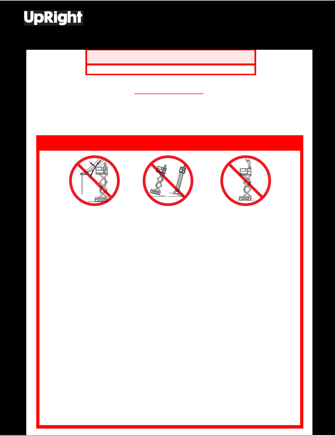
NEVER operate the machine
within ten feet of power lines.
THIS MACHINE IS NOT
INSULATED.
NEVER
drop-offs, bumps and debris.
NEVER
erly torqued.
SECURE
NEVER
NEVER
LOOK
DISTRIBUTE
NEVER
cover)
NEVER
INSPECT
cable, loose wire connections and wheel bolts.
NEVER
NEVER
NEVER
sive hydrogen gas.
AFTER USE
key.
NEVER
out the manufacturer’s consent.
operate the machine without first surveying the work area for surface hazards such as holes,
operate the machine if all guardrails are not properly in place and secured with all fasteners prop-
and lock gate after mounting platform.
use ladders or scaffolding on the platform.
attach overhanging loads or increase platform size.
up, down and around for overhead obstructions and electrical conductors.
all loads evenly on the platform. See the back cover for maximum platform load.
use damaged equipment. (Contact UpRight for instructions. See toll-free phone number on back
change operating or safety systems.
the machine thoroughly for cracked welds, loose hardware, hydraulic leaks, damaged control
climb down elevating assembly with the platform elevated.
perform service on machine while platform is elevated without blocking elevating assembly.
recharge battery near sparks or open flame; batteries that are being charged emit highly explo-
secure the work platform against unauthorized use by turning key switch off and removing
replace any component or part with anything other than original UpRight replacement parts with-
NEVER elevate the platform or
drive the machine while elevated
unless the machine is on firm
level surface.
NEVER sit, stand or climb on
guardrail or midrail.
Safety Rules and Operating Instructions
I
NTRODUCTION
This manual covers the X27 Electric Work Platform. This machine operates on a 48 volt battery
powered system. This manual must be stored on the machine at all times.
PRE-O
DO NOT use a machine that is damaged or malfunctioning. Tag and remove
the unit from service until it is repaired.
PERATION AND SAFETY INSPECTION
Reference:• “Specifications” on page 12
• “Battery Maintenance” on page 9
• “Figure 1:Controls” on page 4
NOTE: Carefully read, understand and follow all safety rules, labels, and operating
instructions, then perform the following steps each day before use.
1. Open panels and check hydraulic components and hoses for damage or leaks. Check electrical components and wiring for damage or loose connections.
2. Inspect chassis, axles, hubs, and steering linkage for damage, deformation, buckled paint,
loose or missing hardware, and cracked welds.
3. With platform fully lowered, check the hydraulic oil level sight gauge on the hydraulic tank. Add
ISO #46 hydraulic oil if necessary.
4. Check that fluid level in all batteries is correct.
5. Check that all guardrails are in place. Insure that gate operates freely and latches securely.
6. Check tires for damage.
7. Carefully inspect the entire work platform for damage such as cracked welds or structural
members, loose or missing parts, oil leaks, damaged cables or hoses, and loose connections.
!
WARNING
!
Page 2 X27 Electric

YSTEM FUNCTION INSPECTION
S
!
WARNING
STAND CLEAR of the work platform while performing the following checks.
Before operating the work platform survey the work area for surface hazards
such as holes, drop-offs, bumps and debris.
Check in ALL directions, including above the work platform, for obstructions
and electrical conductors.
Protect control console cable from possible damage while performing checks.
1. Unhook controller from front guardrail. Firmly grasp controller hanger in such a manner that
the interlock lever can be depressed, while performing the following checks from the ground.
2. Turn platform controller key switch clockwise to ON.
3. Position drive/lift switch to DRIVE position. Drive enable indicator light will be illuminated.
4. With the speed range switch first in LOW SPEED and then again in HIGH SPEED depress
the interlock lever and slowly push the control lever to FORWARD then REVERSE positions
to check for speed and directional control. The farther you push or pull the control lever the
faster the machine will travel.
5. Push steering switch RIGHT then LEFT to check for steering control.
6. Hook controller on guardrail in original position.
7. On chassis controls, turn key switch to Chassis.
8. From lower controls, push chassis raise button to elevate platform while pushing the tilt sensor off of level. The platform should only partially elevate and the tilt alarm should sound. If
the platform continues to elevate and/or there is no alarm STOP and remove the machine
from service until it is repaired.
9. Release the tilt sensor and fully elevate platform.
10. Visually inspect the elevating assembly, lift cylinder, cables and hoses for damage or erratic
operation. Check for missing or loose parts.
11. Lower the platform partially by pushing in on the chassis lower switch, and check operation of
the audible lowering alarm.
12. Open the chassis emergency lowering valve to check for proper operation by pulling and holding the knob out. Once the platform is fully lowered, close the valve by releasing the knob.
13. On chassis controls, turn key switch to platform.
14. Mount the platform making sure the gate is latched.
15. Turn platform controller key switch clockwise to ON. Position drive/lift switch to LIFT.
16. Depress the interlock lever and slowly push the control lever forward to raise the platform, fully
actuate the control lever to check proportional lift speed. Elevate the platform to 12 feet (3.7
m).
17. Slowly pull control lever to DOWN position to lower platform. Check that lowering alarm
sounds.
18. Turn platform controller key switch to OFF, push the emergency stop button and dismount the
platform.
19. Close and secure module covers.
!
Page 3X27 Electric
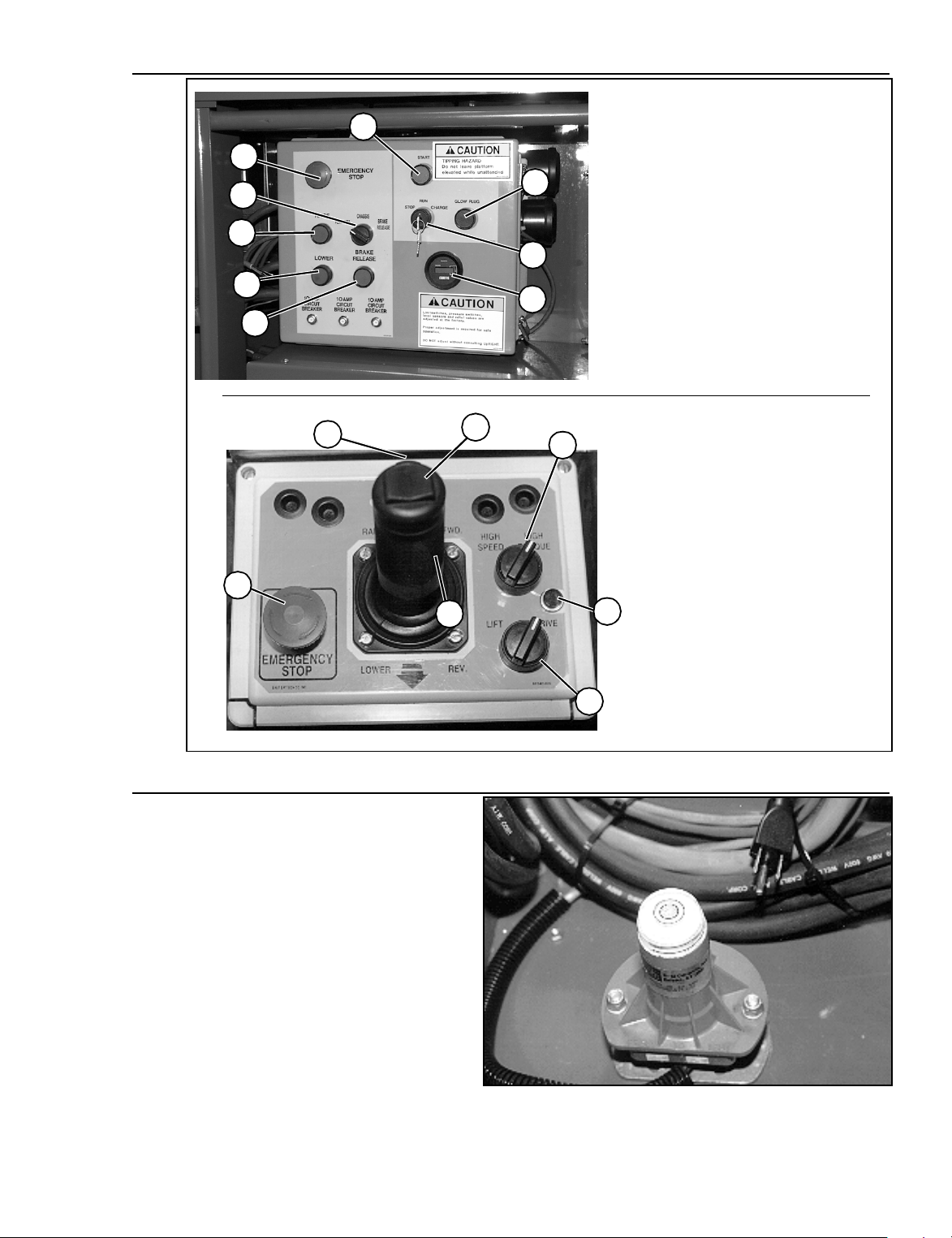
Figure 1:
Controls
Chassis Controls
2
1
3
4
5
6
7
8
9
1. Emergency Stop Button
2. Start Button
3. Platform/Chassis Selector
Switch
4. Raise Button
5. Lower Button
6. Brake Release Button
7. Glow Plug
8. Key Switch
9. Hour Meter
6
5
3
Platform Controls
1. Emergency Stop Button
2. Lift/Drive Selector Switch
3. Speed Range Selector Switch
4. Proportional Control Lever
5. Steering Rocker Switch
6. Interlock Lever
1
4
2
7. Drive Enable Indicator
7
Figure 2:
Level Sensor
Page 4 X27 Electric
 Loading...