

Page 1
Operator Manual
(EN) Manual part number 510352-000 for serial numbers 10000 to current.
X43RT / X52RT
Aug 09
Page 2

Page 3

Page 4
OPERATION MANUAL
WARNING
All personnel shall carefully read, understand and follow all safety rules and operating
instructions before operating or performing maintenance on any UpRight aerial work platform.
Safety Rules
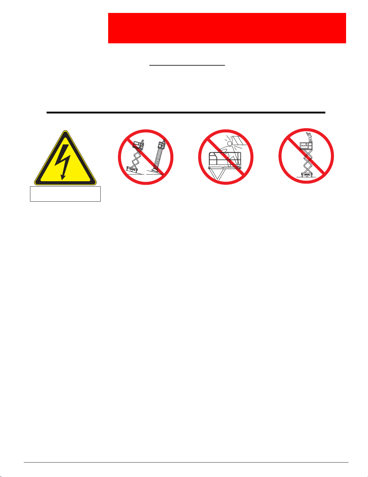
Electrocution Hazard Tip Over Hazard Collision Hazard
THIS MACHINE IS NOT
INSULATED!
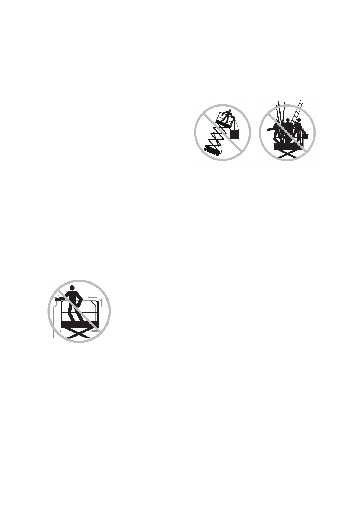
USE OF THE AERIAL WORK PLATFORM: This aerial work platform is intended to lift persons and his tools as well as the material
used for the job. It is designed for repair and assembly jobs and assignments at overhead workplaces (ceilings, cranes, roof structures,
buildings etc.). All other uses of the aerial work platform are prohibited!
THIS AERIAL WORK PLATFORM IS NOT INSULATED! For this reason it is imperative to keep a safe distance from live parts of electrical equipment!
Exceeding the specified permissible maximum load is prohibited! See “Special Limitations” on page 4 for details.
The use and operation of the aerial work platform as a lifting tool or a crane (lifting of loads from below upwards or from up high on
down) is prohibited!
NEVER exceed the manual force allowed for this machine. See “Special Limitations” on page 4 for details.
DISTRIBUTE all platform loads evenly on the platform.
NEVER operate the machine without first surveying the work area for surface hazards such as holes, drop-offs, bumps, curbs, or debris;
and avoiding them.
OPERATE machine only on surfaces capable of supporting wheel loads.
NEVER operate the machine when wind speeds exceed this machine’s wind rating. See “Beaufort Scale” on page 4 for details.
IN CASE OF EMERGENCY push EMERGENCY STOP switch to deactivate all powered functions.
IF ALARM SOUNDS while platform is elevated, STOP, carefully lower platform. Move machine to a firm, level surface.
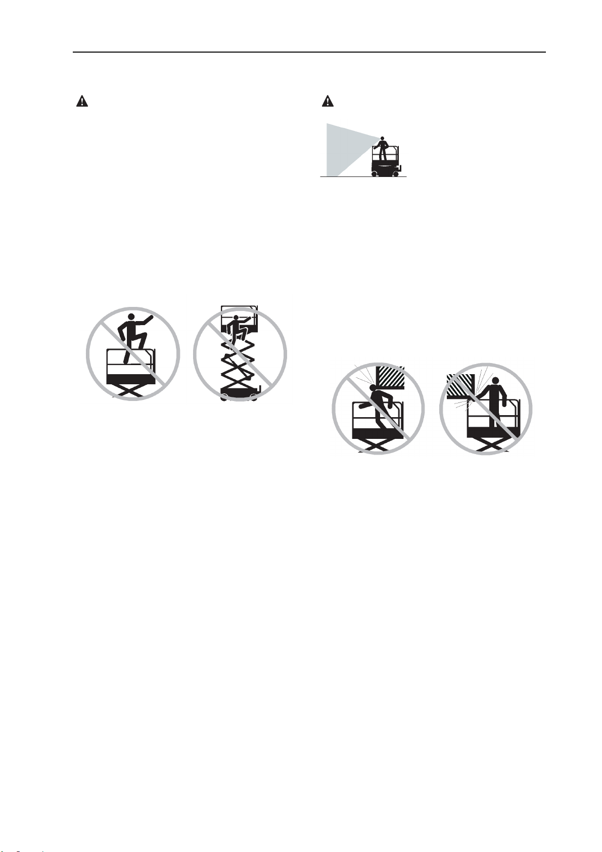
Climbing up the railing of the platform, standing on or stepping from the platform onto buildings, steel or prefab concrete structures, etc.,
is prohibited!
Dismantling the swing gate or other railing components is prohibited! Always make certain that the swing gate is closed and securely
locked!
It is prohibited to keep the swing gate in an open position (held open with tie-straps) when the platform is raised!
To extend the height or the range by placing of ladders, scaffolds or similar devices on the platform is prohibited!
NEVER perform service on machine while platform is elevated without blocking elevating assembly.
INSPECT the machine thoroughly for cracked welds, loose or missing hardware, hydraulic leaks, loose wire connections, and damaged
cables or hoses before using.
VERIFY that all labels are in place and legible before using.
NEVER use a machine that is damaged, not functioning properly, or has damaged or missing labels.
To bypass any safety equipment is prohibited and presents a danger for the persons on the aerial work platform and in its working
range.
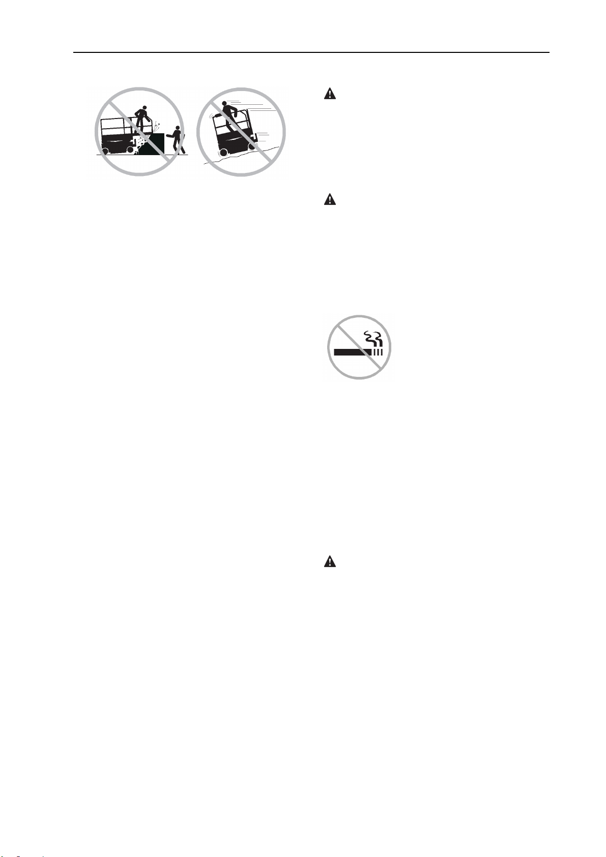
NEVER charge batteries near sparks or open flame. Charging batteries emit explosive hydrogen gas.
Modifications to the aerial work platform are prohibited or permissible only at the approval by UpRight.
AFTER USE, secure the work platform from unauthorized use by turning both keyswitches off and removing key.
The driving of MEWPs on the public highways is subject to regulations made under the Road Traffic Acts.
NEVER elevate the platform or drive
the machine while elevated unless the
machine is on a firm, level surface.
NEVER position the platform
without first checking for overhead
obstructions or other hazards.
Fall Hazard
NEVER climb, stand, or sit on
platform guardrails or midrail.
Page 5

OPERATOR’S MANUAL with Maintenance Information
Important
Read, understand and obey these safety rules
r
and ope
machine.
Only trained and authorized personnel shall be
permitted to operate this machine. This manual
should be considered a permanent part of your
machine and should remain with the machine
at all times. If you have any questions, please
call UPRIGHT.
Contents
Page
Safety Rules 1
Control panel 9
ating instructions before operating this
Owners, Users and operators:
We appreciates your choice of our machine for
your app
user safety, which is best achieved by our joint
efforts. We feel that you make a major
contribution to safety if you, as the equipment
users and operators:
1. Comply with employer, job site and
2. Read, understand and follow the
3. Use good safe work practices in a
4. 0nly have trained / certified operators,
lication. Our number one priority is
governmental rules.
instructions in this and other manuals
supplied with this machine.
commonsense way.
directed by informed and knowledgeable
supervision, running the machine.
Pre-operation Inspection 1
Maintenance 14
Function Tests 17
Workplace Inspection 22
erating Instructions 2
Op
Transport and Lifting Instructions 29
Decals 32
Specifications 35
Schematic 37
1
4
If there is anything in this manual that is not
clear or which you believe should be added,
please contact us.
Contact us:
i
Page 6
OPERATOR’S MANUAL with Maintenance Information
Safety Rules
Danger
Failure to obey the instructions and
safety rules in this manual will result
in death or serious injury.
Do Not Operate Unless:
You learn and practice the principles of safe
machine op
manual.
√ 1 Avoid hazardous situations.
Know and understand the safety rules
before going on to the next section.
2 Always perform a pre-operation
inspection.
3 Always perform function tests prior to use.
eration contained in this operator's
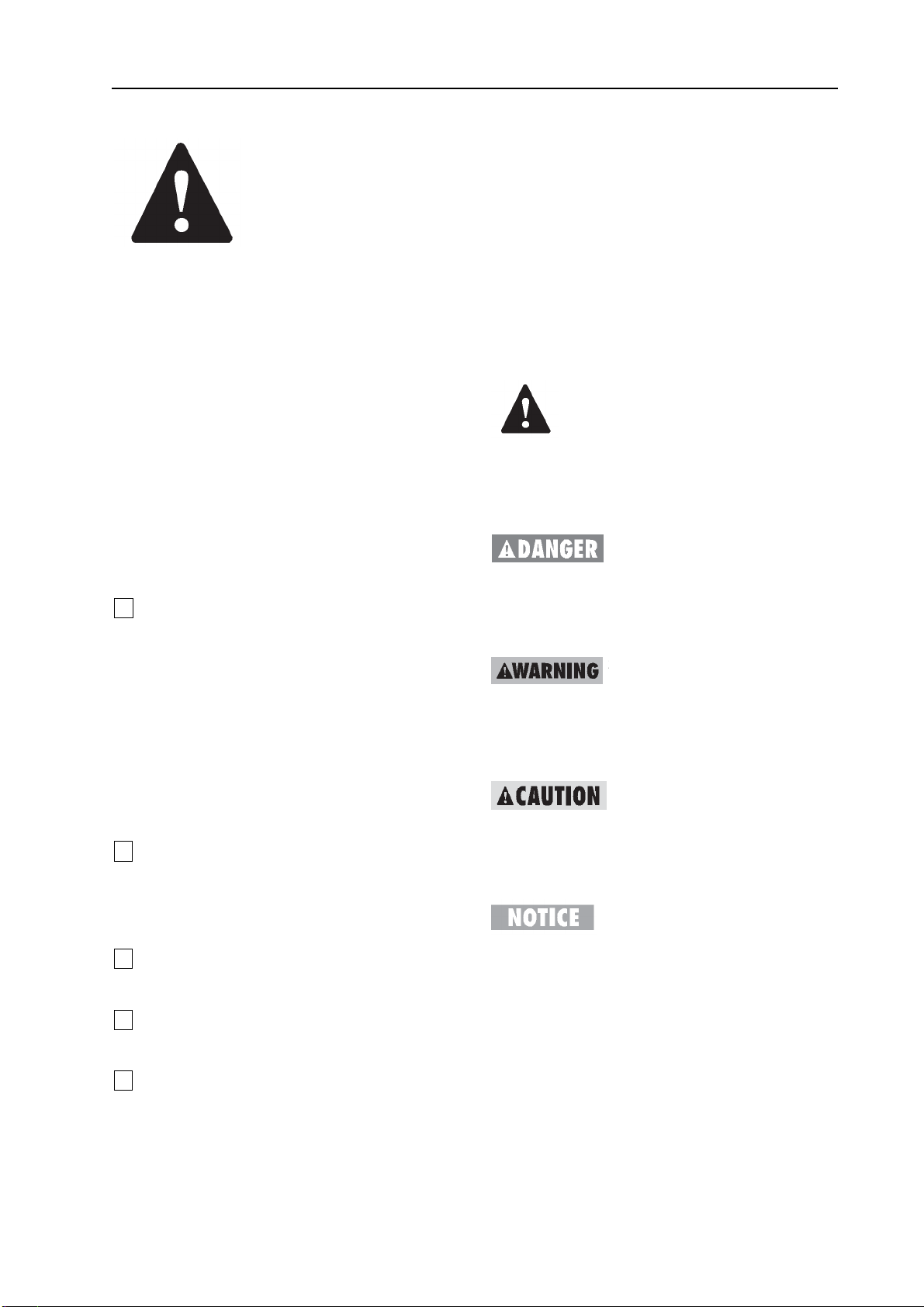
Decal Legend
UPRIGHT product decals use symbols, color
codi
ng and signal words to identify the
following:
Safety alert symbol—used to alert
personnel to potential personal injury hazards.
Obey all safety messages that follow this
symbol to avoid possible injury or death.
Red—used to indicate the
presence of an imminently hazardous situation
which, if not avoided, will result in death or
serious injury.
Orange—used to indicate the
presence of a potentially hazardous situation
which, if not avoided, could result in death or
serious injury.
4 Inspect the workplace.
5 Only use the machine as it was intended.
√ You read, understand and obey the
manufacturer's instructions and safety rules—
safety and operator's manuals and machine
decals.
√ You read, understand and obey employer's
safety rules and worksite regulations.
√ You read, understand and obey all
applicable governmental regulations.
√ You are properly trained to safely operate
the machine.
Yellow with safety alert symbolused to indicate the presence of a potentially
hazardous situation which, if not avoided, may
cause minor or moderate injury.
Yellow without safety alert
symbol—used to indicate the presence of a
potentially hazardous situation which, if not
avoided, may result in property damage.
1
Page 7
OPERATOR’S MANUAL with Maintenance Information
Safety Rules
Electrocution Hazards
This machine is not electrically insulated and
will not provide protection from contact with or
proximity to electrical current.
Maintain safe distances from electrical power
lines and apparatus in accordance with
applicable governmental regulations and the
following chart.
Voltage
Phase to Phase
0 to 300V Avoid Contact
300V to 50KV 3.05
50KV to 200KV 4.60
200KV to 350KV 6.10
350KV to 500KV 7.62
500KV to 750KV 10.67
750KV to 1000KV 13.72
Minimum Safe
Approach Distance
Meters
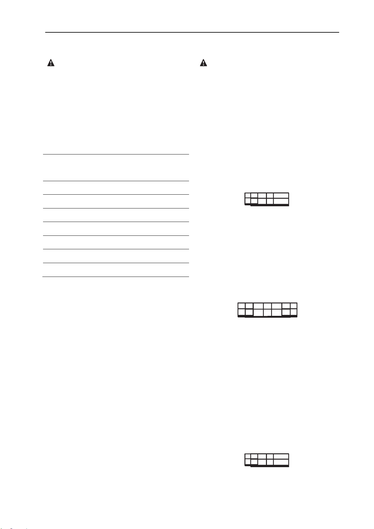
Tip-over Hazards
Occupants, equipment and materials must not
exceed the maximum platform capacity.
Maximum capacity – X43RT
Maximum occupants 7
Models with one extension deck
Platform retracted 680 kg
Only platform 454 kg
Only extension deck 227 kg
Only Only platform
Extension
deck 454kg
227kg
dels with one extension deck
Mo
Platform retracted 680 kg
Platform with one extension deck 454 kg
Platform with one extension deck 227kg
Allow for platform movement, electrical line
sway or sag and beware of strong or gusty
winds.
Keep away from the machine if it contacts
energized power lines. Personnel on the ground
or in the platform must not touch or operate the
machine until energized power lines are shut
off.
Do not operate the machine during lightning or
storms.
Do not use the machine as a ground for
welding.
For each extension deck 227 kg
Only Only
Extension Only platform Extension
deck deck
227kg 227kg 227kg
Maximum capacity – X52RT
Maximum occupants 6
Models with one extension deck
Platform retracted 680 kg
Only platform 454 kg
Only extension deck 227 kg
Only Only platform
Extension
deck 454kg
227kg
2
Page 8

OPERATOR’S MANUAL with Maintenance Information
Safety Rules
Models
Platform retracted 680 kg
Platform with one extension deck 454 kg
Platform with one extension deck 227kg
For each extension deck 227 kg
Only Only
Extension Only platform Extension
deck deck
227kg 227kg 227kg
with one extension deck
Do not raise the platform unless the machine is
on a firm, level surface.
Do not drive over 1.1 km/h with the platform
raised.
Do not depend on the tilt alarm as a level
indicator.
The tilt alarm sounds on the chassis and in the
platform when the machine is on a slope.
If the tilt alarm sounds:
Lower the platform. Move the machine to a firm,
level surface. If the tilt alarm sounds when the
platform is raised, use extreme caution to lower
the platform.
Do not raise the platform when wind speeds
may exceed 12.5 m/s. If wind speeds exceed
12.5 m/s when the platform is raised, lower the
platform and do not continue to operate the
machine.
Do not operate the machine in strong or gusty
winds. Do not increase the surface area of the
platform or the load. Increasing the area
exposed to the wind will decrease machine
stability.
Do not use the platform controls to free a
platform that is caught, snagged or otherwise
prevented from normal motion by an adjacent
3
Page 9
OPERATOR’S MANUAL with Maintenance Information
Safety Rules
structure. Al
the platform before attempting to free the
platform using the ground controls.
Use extreme care and slow speeds while
driving the machine in the stowed position
across uneven terrain, debris, unstable or
slippery surfaces and near holes and drop-offs.
Do not drive the machine on or near uneven
terrain, unstable surfaces or other hazardous
conditions with the platform raised.
Do not use the machine as a crane.
Do not place or attach fixed or overhanging
loads to any part of this machine.
Do not push the machine or other objects with
the platform.
Do not contact adjacent structures with the
Platform
Do not alter or disable the limit switches.
l personnel must be removed from
weight in the platform and the surface area of
the platform or the load.
Do not replace items critical to machine stability
with items of different weight or specification.
Do not place ladders or scaffolds in the platform
or against any part of this machine.
Do not transport tools and materials unless they
are evenly distributed and can be safely
handled by person(s) in the platform.
Do not use the machine on a moving or mobile
surface or vehicle.
Do not push off or pull toward any object
outside of the platform.
Maximum allowable manual force 400 N
Do not tie the platform to adjacent structures.
Do not place loads outside the platform
perimeter.
Do not alter or disable machine components
that in any way affect safety and stability.
Do not modify or alter an aerial work platform
without prior written permission from the
manufacturer. Mounting attachments for holding
tools or other materials onto the platform,
toeboards or guard rail system can increase the
Be sure all tires are in good condition, air-filled
tires are properly inflated and lug nuts are
properly tightened.
Do not drive the machine on a slope that
exceeds the slope and side slope rating of the
machine.
Slope rating applies to machines in the stowed
position.
X43RT
Maximum slope
Maximum side slope rating, stowed position
50% (26°) X52RT
Maximum slope rating, stowed position 40%
Maximum side slope rating, stowed position
40% (22°)
Note: Slope rating is subject to ground
conditions and adequate traction.
4
rating, stowed position 50%
Page 10
OPERATOR’S MANUAL with Maintenance Information
Safety Rules
Fall Hazards
The guard rail system provides fall protection. If
occupant(s) of the platform are required to wear
personal fall protection equipment (PFPE) due
to job site or employer rules, PFPE equipment
and its use shall be in accordance with the
PFPE manufacturer’s instructions and
applicable governmental requirements.
Do not sit, stand or climb on the platform guard
rails. Maintain a firm footing on the platform
floor at all times.
Collision Hazards
Be aware of limited sight distance and blind
spots when driving or operating.
Be aware of extended platform position(s) when
moving the machine.
Operators must comply with employer, job site
and governmental rules regarding use of
personal protective equipment.
Check the work area for overhead obstructions
or other possible hazards.
Do not climb down from the platform when
raised.
Keep the platform floor clear of debris.
Close the entry gate before operating.
Do not operate the machine unless the guard
rails are properly installed and the entry is
secured for operation.
Be aware of crushing hazards when grasping
the platform guard rail.
Observe and use color-coded direction arrows
on the platform controls and platform decal
plate for drive and steer functions.
Do not operate a machine in the path of any
crane or moving overhead machinery unless
the controls of the crane have been locked out
and/or precautions have been taken to prevent
any potential collision.
No stunt driving or horseplay while operating a
machine.
Do not lower the platform unless the area below
is clear of personnel and obstructions.
5
Page 11
OPERATOR’S MANUAL with Maintenance Information
Safety Rules
Component Damage Hazards
Do not use any battery or charger greater than
12V to jump-start the engine.
Do not use the machine as a ground for
welding.
Limit travel speed according to the condition of
the ground surface, congestion, slope, location
of personnel, and any other factors which may
cause collision.
Explosion and Fire Hazards
Do not start the engine if you smell or detect
liquid p
or other explosive substances.
Do not refuel the machine with the engine
running.
Refuel the machine and charge the battery only
in an open, well-ventilated area away from
sparks, flames and lighted tobacco.
Do not operate the machine in hazardous
locations or locations where potentially
flammable or explosive gases or particles may
be present.
etroleum gas (LPG), gasoline, diesel fuel
Do not spray ether into engines equipped with
glow plugs.
Damaged Machine Hazards
Do not use a damaged or malfunctioning
machine.
Conduct a thorough pre-operation inspection of
the machine and test all functions before each
work shift. Immediately tag and remove from
service a damaged or malfunctioning machine.
Be sure all maintenance has been performed as
specified in this manual and the appropriate
UPRIGHT service manual.
Be sure all decals are in place and legible.
Be sure the operator’s, safety and
6
Page 12

OPERATOR’S MANUAL with Maintenance Information
Safety Rules
responsib
and in the storage container located in the
platform.
ilities manuals are complete, legible
Crushing Hazards
Keep hands and limbs out of scissors.
Use common sense and planning when
operating the machine with the controller from
the ground. Maintain safe distances between
the operator, the machine and fixed objects.
Maintain a firm grasp on the platform rail when
removing the rail pins. Do not allow the platform
guard rails to fall.
Bodily Injury Hazard
Always operate the machine in a well-ventilated
area to avoid carbon monoxide poisoning.
Do not operate the machine with a hydraulic oil
or air leak. An air leak or hydraulic leak can
penetrate and/or burn skin.
Improper contact with components under any
cover will cause serious injury. Only trained
maintenance personnel should access
compartments. Access by the operator is only
advised when performing a pre-operation
inspection. All compartments must remain
closed and secured during operation.
Outrigger Safety
Do not lower the outriggers unless the machine
is on a firm surface. Avoid drop-offs, holes,
unstable or slippery surfaces and other possible
hazardous conditions.
When the auto level function is not being used
and the outriggers are being lowered
individually, the steer-end outriggers must be
lowered first.
Do not raise the platform unless the machine is
level. Do not set the machine up on a surface
where it cannot be leveled using only the
outriggers.
Do not raise the platform unless all four
outriggers are properly lowered, the footpads
are in firm contact with the ground and the
machine is level.
Do not adjust the outriggers while the platform
is raised.
Do not drive while the outriggers are lowered.
7
Page 13
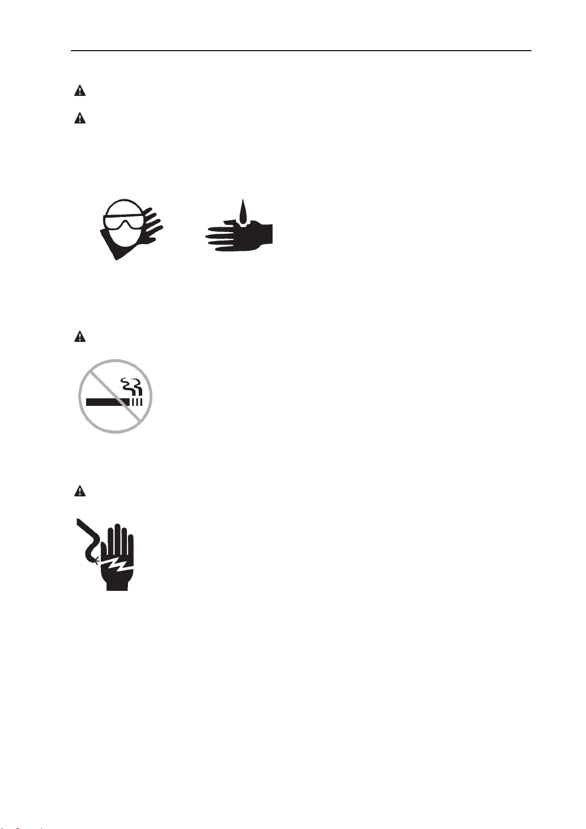
Battery Safety
Burn Hazards
Batteries contain acid. Always wear protective
clothing and eye wear when working with
batteries.
Avoid spilling or contacting battery acid.
Neutralize battery acid spills with baking soda
and water.
OPERATOR’S MANUAL with Maintenance Information
Safety Rules
Explosion Hazard
Keep sparks, flames and lighted tobacco away
from batteries. Batteries emit explosive gas.
Electrocution Hazard
Avoid contact with electrical terminals.
8
Page 14
OPERATOR’S MANUAL with Maintenance Information
Safety Rules
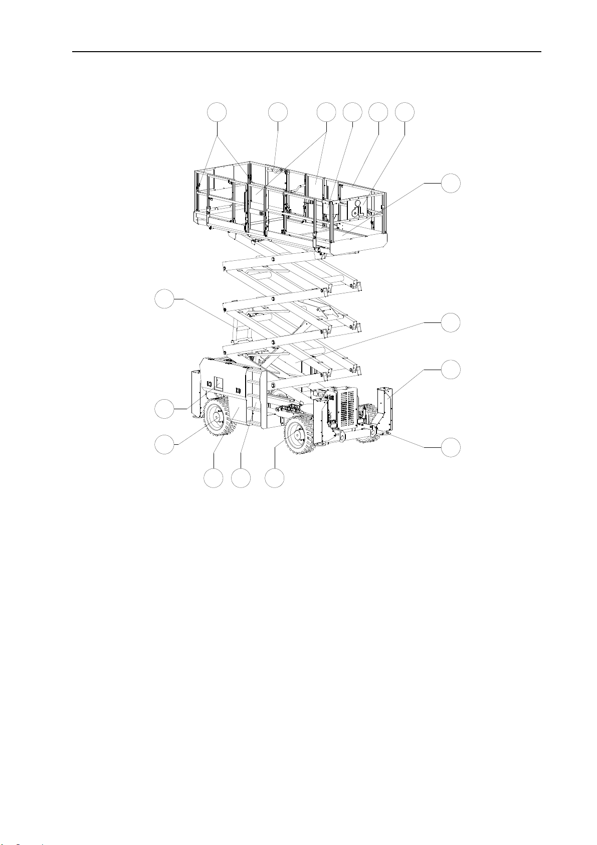
1 Lanya
2 Platform extension lock handle
3 Platform entry gate
4 Platform controls
5 Platform guard rails
6 Manual storage container
7 Platform extension
8 Hydraulic tank (behind cover)
9 Outrigger housing (if equipped)
rd anchorage point
16
15
14
1 2 3 4 5 6
13 12 11
10 Outrigger footpad (if equipped)
11 Steer tire
12 Entry ladder
13 Fuel tank (behind cover)
14 Non-steer tire
15 Ground controls with LCD readout screen
16 Safety arm (hidden from view)
7
8
9
10
9
Page 15
OPERATOR’S MANUAL with Maintenance Information
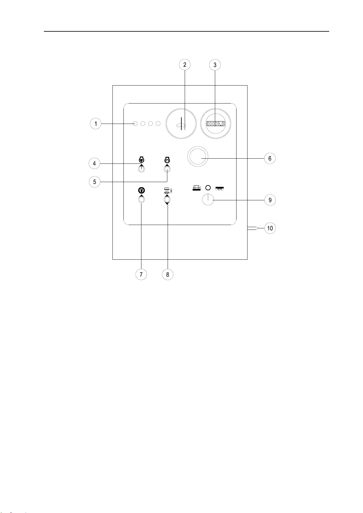
Control Panel
Ground Control Panel
1 LCD indicator light 6 Red Emergency Stop button
2 Fuel meter 7 Lift function enable switch
3 Hour meter 8 Platform up / down switch
4 Idle select switch 9 Key switch for platform / off / ground control selection
5 Engine start switch 10 Outrigger auxiliary retract switch
10
Page 16
OPERATOR’S MANUAL with Maintenance Information
Control Panel
2
3
4
5
6
7
8
1
18
17
16
15
14
9
1211 1310
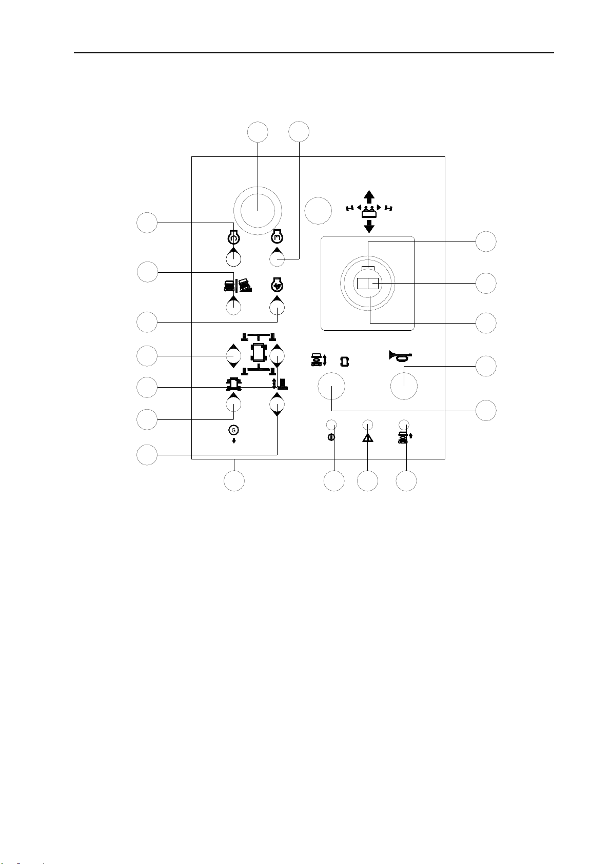
Platform Controls
1 Engine glow plug switch 10 Auxiliary lowering function switch
2 Red Emergency Stop button 11 Power indicator light
3 Engine start switch 12 Alarm indicator light
4 Machine on incline switch 13 Lift function indicator light
5 Idle select switch 14 Lift function enable switch
6 Left outrigger control switch 15 Horn button
7 Right outrigger control switch 16 Proportional control handle for drive function
8 Outrigger auto level switch 17 Thumb rocker switch for steer function
9 Outrigger extend / retract switch 18 Function enable switch
11
Page 17

OPERATOR’S MANUAL with Maintenance Information
Pre-operation Inspection
Do Not Operate Unless:
√ You learn and practice the principles of
safe machine operation contained in this
operator's manual.
1 Avoid hazardous situations.
2 Always perform a pre-operation
inspection.
Know and understand the pre-operation
inspection before going on to the next
section.
3 Always perform function tests prior to use.
4 Inspect the workplace.
5 Only use the machine as it was intended.
Fundamentals
It is the responsibility of the operator to perform
a pre-o
maintenance.
The pre-operation inspection is a visual
inspection performed by the operator prior to
each work shift. The inspection is designed to
discover if anything is apparently wrong with a
machine before the operator performs the
function tests.
The pre-operation inspection also serves to
determine if routine maintenance procedures
are required. Only routine maintenance items
specified in this manual may be performed by
the operator.
Refer to the list on the next page and check
each of the items.
peration inspection and routine
If damage or any unauthorized variation from
factory delivered condition is discovered, the
machine must be tagged and removed from
service.
Repairs to the machine may only be made by a
qualified service technician, according to the
manufacturer's specifications. After repairs are
completed, the operator must perform a
pre-operation inspection again before going on
to the function tests.
Scheduled maintenance inspections shall be
performed by qualified service technicians,
according to the manufacturer's specifications
and the requirements listed in the
responsibilities manual.
12
Page 18

OPERATOR’S MANUAL with Maintenance Information
Pre-operation Inspection
Pre-operation Inspection
Be sure that the operator’s, safety and
□
responsibilities manuals are complete, legible
and in the storage container located in the
platform.
□ Be sure that all decals are legible and in
place. See Decals section.
□ Check for engine oil leaks and proper oil
level. Add oil if needed. See Maintenance
section.
□ Check for hydraulic oil leaks and proper oil
level. Add oil if needed. See Maintenance
section.
□ Check for engine coolant leaks and proper
level of coolant. Add coolant if needed. See
Maintenance section.
□ Check for battery fluid leaks and proper fluid
level. Add distilled water if needed. See
Maintenance section.
□ Platform entry gate
□ Beacon and alarms (if equipped)
□ Safety arm
□ Platform extension(s)
□ Scissor pins and retaining fasteners
□ Platform control joystick
□ Generator (if equipped)
□ Outrigger housings and footpads (if
equipped)
Check entire machine for:
□ Cracks in welds or structural components
□ Dents or damage to machine
□ Be sure that all structural and other critical
components are present and all associated
fasteners and pins are in place and properly
tightened
Check the following components or areas for
damage, improperly installed or missing parts
and unauthorized modifications:
□ Electrical components, wiring and
electrical cables
□Hydraulic hoses, fittings, cylinders and
manifolds
□ Fuel and hydraulic tanks
□ Drive motors
□ Wear pads
□ Tires and wheels
□ Engine and related components
□ Limit switches, alarms and horn
□ Nuts, bolts and other fasteners
□ Side rails are installed and rail pins and
bolts are fastened
□ Platform overload components
13
Page 19

OPERATOR’S MANUAL with Maintenance Information
Maintenance
Observe and Obey:
□ Only routine maintenance items specified in
this manual shall be performed by the operator.
□ Scheduled maintenance inspections shall be
completed by qualified service technicians,
according to the manufacturer's specifications
and the requirements specified in the
responsibilities manual.
Maintenance Symbols Legend
The following symbols have
been used in this manual to help communicate
the intent of the instructions. When one or more
of the symbols appear at the beginning of a
maintenance procedure, it conveys the
meaning below.
Check the Batteries
Proper battery condition is essential to good
engine performance and operational safety.
Improper fluid levels or damaged cables and
connections can result in engine component
damage and hazardous conditions.
Electrocution hazard
Contact with hot or live circuits may result in
death or serious injury. Remove all rings,
watches and other jewelry.
Bodily injury hazard
Batteries contain acid. Avoid spilling or
contacting battery acid. Neutralize battery acid
spills with baking soda and water.
Indicates that tools will be required to
perform this procedure.
Indicates that new parts will be required
to perform this procedure.
Indicates that a cold engine is required
before performing this procedure.
1 Put on protective clothing and eye wear.
2 Be sure that the battery cable
connections are tight and free of
corrosion.
3 Be sure that the battery hold-down bars
are secure.
4 Remove the battery vent caps.
5 Check the battery acid level. If needed,
replenish with distilled water to the bottom
of the battery fill tube. Do not overfill.
6 Install the vent caps.
14
Page 20

OPERATOR’S MANUAL with Maintenance Information
Maintenance
Check the Engine Oil Level
Maintaining the proper engine oil level is
essential to good engine performance and
service life.
Operating the machine with an improper oil
level can damage engine components.
Check the oil level with the
engine off.
1 Release the latches on the engine tray and
fully slide the engine tray out.
2 Check the oil level dipstick. Add oil as
needed.
Perkins 404C-22
Oil Type 5W-30
Oil Type - cold conditions 0W-20
Check the H
Maintaining the hydraulic oil at the proper level
is essential to machine operation. Improper
hydraulic oil levels can damage hydraulic
components. Daily checks allow the inspector to
identify changes in oil level that might indicate
the presence of hydraulic system problems.
platform in the stowed position and the engine
off.
1 Visually inspect the sight gauge located on
the side of the hydraulic oil tank.
☉☉☉☉Result: The hydraulic oil level should be
within the top 5 cm of the sight gauge.
2 Add oil if necessary. Do not overfill.
Hydraulic oil specifications
-18℃~-5℃ 10W
ydraulic Oil Level
Perform this procedure with the
-18℃~99℃ 10W-20,10W-30
15
Page 21

OPERATOR’S MANUAL with Maintenance Information
Maintenance
Check the Engine Coolant Level
Maintaining the engine coolant at the proper
level is essential to engine service life. Improper
coolant level will affect the engine's cooling
capability and damage engine components.
Daily checks will allow the inspector to identify
changes in coolant level that might indicate
cooling system problems.
Check the fluid level in the radiator. Add fluid as
needed.
Bodily injury hazard
Fluids in the radiator are under pressure and
extremely hot. Use caution when removing cap
and adding fluids.
Scheduled Maintenance
Maintenance performed quarterly, annually and
every t
trained and qualified to perform maintenance on
this machine according to the procedures found
in the service manual for this machine.
Machines that have been out of service for
more than three months must receive the
quarterly inspection before they are put back
into service.
wo years must be completed by a person
16
Page 22

OPERATOR’S MANUAL with Maintenance Information
Function Tests
Do Not Operate Unless:
√ You learn and practice the principles of safe
machine operation contained in this operator's
manual.
1 Avoid hazardous situations.
2 Always perform a pre-operation inspection.
3 Always perform function tests prior to
use.
Know and understand the function tests
before going on to the next section.
4 Inspect the workplace.
5 Only use the machine as it was intended.
Fundamentals
The function tests are designed to discover any
malfunct
service.
The operator must follow the step-by-step
instructions to test all machine functions.
A malfunctioning machine must never be used.
If malfunctions are discovered, the machine
must be tagged and removed from service.
Repairs to the machine may only be made by a
qualified service technician, according to the
manufacturer's specifications.
After repairs are completed, the operator must
perform a pre-operation inspection and function
tests again before putting the machine into
service.
ions before the machine is put into
17
Page 23

OPERATOR’S MANUAL with Maintenance Information
Function Tests
1 Select a
of obstruction.
test area that is firm, level and free
At the Ground Controls
2 Pull out the platform and ground red
Emergency
3 Turn the key switch to ground control.
☉☉☉☉ Result: The LCD indicator will light one by
one.
4 Start the engine. See Operating Instructions
section.
Test Emergency Stop
5 Push in the ground red Emergency Stop
button to
☉☉☉☉ Result: The engine should turn off and no
functions should operate.
6 Pull out the red Emergency Stop button to
the on position and restart the engine.
Test Up/Down Functions and Function
Enable
The audible warnings on this machine come
from the
constant tone. The descent alarm sounds at 60
beeps per minute. The alarm that goes off when
the machine is not level sounds.
same central alarm. The horn is a
Stop buttons to the on position.
the off position.
(X52RT). The descent alarm should
sound w
10 Move up and hold the lift function enable
switch. Move down and hold the platform
down switch.
☉☉☉☉Result: The platform should lower to end. The
descent alarm should sound while the
platform is lowering.
hile the platform is lowering.
Test the Auxiliary Lowering
11 Move up and hold the lift function enable
switch and
60 cm.
12 Push in the red Emergency Stop button to
shut off the engine.
13 Pull out the red Emergency Stop button to
the on position.
14 Move down and hold the engine start switch.
Move down and hold the platform down
switch.
☉☉☉☉ Result: The platform should lower.
15 Turn the key switch to platform control and
restart the engine.
raise the platform approximately
7 Do not move the lift function enable switch
up. Move up and hold the platform switch.
☉☉☉☉ Result: No function should operate.
8 Move and hold the lift function enable
switch up. Move and hold the platform up
switch up.
☉☉☉☉ Result: The platform should raised .
9 Move up and hold the lift function enable
switch. Move down and hold the platform
down switch.
☉☉☉☉ Result: The platform should lower then stop
at the height is 2 m (X43RT) or 3m
18
Page 24

OPERATOR’S MANUAL with Maintenance Information
Function Tests
At the Platform Controls
Test Emergency Stop
16 Push in the platform red Emergency Stop
utton to the off position.
b
☉☉☉☉ Result: No functions should operate.
17 Pull the red Emergency Stop button out to
the on position.
☉☉☉☉ Result: The LED indicator light should come
on.
Test the Horn
18 Push the horn button.
☉☉☉☉ Result
Test Up/Down Functions and Function
Enable
19 Start the engine.
20 Activate the up/down rocker switch in the
☉☉☉☉ Result: The platform should not raised.
21 Push and hold the lift function enable
22 Activate the up/down rocker switch in the
☉☉☉☉ Result: The platform should raise.
: The horn should sound.
direction indicated by the up arrow.
button.
direction indicated by the up arrow.
25 Press and hold the function enable switch
on the control handle.
26 Depress the thumb rocker switch on top of
the control handle in the direction identified
by the left triangle on the control panel.
☉☉☉☉ Result: The steer wheels should turn in the
direction that the left triangle points on the
control panel.
27 Depress the thumb rocker switch in the
direction identified by the right triangle on
the control panel.
☉☉☉☉ Result: The steer wheels should turn in the
direction that the right triangle points on the
control panel.
Test Drive and Braking
28 Press and hold the function enable switch
on the
29 Slowly move the control handle in the
direction indicated by the up arrow on the
control panel until the machine begins to
move, then return the handle to the center
position.
☉☉☉☉ Result: The machine should move in the
direction that the up arrow points on the
control panel, then come to an abrupt stop.
30 Press and hold the function enable switch
on the control handle.
control handle.
23 Push and hold the lift function enable
button.
24 Activate the up/down rocker switch in the
direction indicated by the down arrow.
☉☉☉☉ Result: The platform should lower. The
descent alarm should sound while the
platform is lowering.
Test the Steering
Note: When performing the steer and drive
function
steer end of the machine.
tests, stand in the platform facing the
31 Slowly move the control handle in the
direction indicated by the down arrow on the
control panel until the machine begins to
move, then return the handle to the center
position.
☉☉☉☉ Result: The machine should move in the
direction that the down arrow points on the
control panel, then come to an abrupt stop.
Note: The brakes must be able to hold the
machine on any slope it is able to climb.
19
Page 25

OPERATOR’S MANUAL with Maintenance Information
Function Tests
Test Limited Drive Speed
32 Push and hold the lift function enable button.
Raise the platform approximately 2 m
(X43RT) or 3m (X52RT) from
the ground.
33 Press and hold the function enable switch
on the control handle.
34 Slowly move the control handle to the full
drive position.
☉☉☉☉ Result: The maximum achievable drive
speed with the platform raised should not
exceed 31 cm/s. If the drive speed with the
platform raised exceeds 31 cm/s,
immediatel
from service.
y tag and remove the machine
Test the Tilt Sensor Operation
Note: Perform this test from the ground with the
platform controller. Do not stand in the platform.
35 Fully lower the platform.
off the block.
Test the Up Limit Switch and the
Outriggers
4
2 Push and hold the lift function enable button.
Raise the platform.
☉☉☉☉ Result: The platform should raise to 9 m and
then stop. The platform should not raise
above 9 m unless the outriggers are
lowered.
43 Turn the lift function enable switch to drive
function. Drive the machine forward.
☉☉☉☉ Result: The drive function should not
operate.
44 Turn the lift function enable switch to lift
function.
45 Lower the platform. If the platform is higher
than 2 m (X43RT) or 3m
(X52RT) from the ground,
triggers will not lower.
the ou
36 Drive both wheels on one side onto an 18
cm block.
37 Raise the platform at least 2 m
(X43RT) or 3m (X52RT).
☉☉☉☉ Result:
alarm will sound. The indicator light on the
lift function enable button will be red.
38 Turn the lift function enable switch to drive
39 Move the drive control handle in the
☉☉☉☉ Result: The drive function should not work in
either direction.
40 Turn the lift function enable switch to lift
41 Lower the platform and drive the machine
The platform should stop and the tilt
function.
direction indicated by the up arrow, then
move the drive control handle in the
direction indicated by the down arrow.
function.
46 Lower the platform to the end.
47 Move the outrigger extend / retract switch
down.
48 Move outrigger auto leveling switch up.
☉☉☉☉ Result: The outriggers should extend and
level the machine. A beep will sound when
the machine is level.
49 Raise the platform.
☉☉☉☉ Result: The platform should raise to full
height.
50 Lower the platform.
Test Auxiliary Lowering
51 Push and hold the lift function enable button
and raise
52 Push in the red Emergency Stop button to
shut off the engine.
the platform approximately 60 cm.
20
Page 26

OPERATOR’S MANUAL with Maintenance Information
Function Tests
53 Pull
54 Move the auxiliary lowering function switch
☉☉☉☉ Result: The platform should lower.
out the red Emergency Stop button to
the on position.
up. Push and hold the lift function enable
button. Activate the up/down rocker switch
in the direction indicated by the down arrow.
Test Outrigger Auxiliary Retract
55 Lower the platform to the lowest position.
56 Oper
57 Open the ground control gate. Move down
58 Move up the outrigger auxiliary retract
ator comes back to the ground control.
Operation the machine on the ground
control.
and hold the engine start switch.
switch.
☉☉☉☉ Result: The outrigger should retract.
21
Page 27

OPERATOR’S MANUAL with Maintenance Information
Workplace Inspection
Do Not Operate Unless:
√ You learn and practice the principles of safe
machine operation contained in this operator's
manual.
1 Avoid hazardous situations.
2 Always perform a pre-operation inspection.
3 Always perform function tests prior to use.
4 Inspect the workplace.
Know and understand the workplace
inspection before going on to the next
section.
5 Only use the machine as it was intended.
Fundamentals
The workplace inspection helps the operator
determi
machine operation. It should be performed by
the operator prior to moving the machine to the
workplace.
It is the operator's responsibility to read and
remember the workplace hazards, then watch
for and avoid them while moving, setting up and
operating the machine.
ne if the workplace is suitable for safe
22
Page 28

OPERATOR’S MANUAL with Maintenance Information
Workplace Inspection
Be aware of and avoid the following hazardous
situations:
- Drop-offs or holes
- Bumps, floor obstructions or debris
- Sloped surfaces
- Unstable or slippery surfaces
- Overhead obstructions and high voltage
conductors
- Hazardous locations
- Inadequate surface support to withstand all
load forces imposed by the machine
Workplace Inspection
- Wind and weather conditions
- The presence of unauthorized personnel
- Other possible unsafe conditions
23
Page 29

Do Not Operate Unless:
√ You learn and practice the principles of
safe machine operation contained in this
operator's manual.
1 Avoid hazardous situations.
2 Always perform a pre-operation inspection.
3 Always perform function tests prior to use.
4 Inspect the workplace.
5 Only use the machine as it was intended.
OPERATOR’S MANUAL with Maintenance Information
Operating Instructions
Fundamentals
The Operating Instructions section provides
instructi
operation.
It is the operator's responsibility to follow all the
safety rules and instructions in the operator's,
safety and responsibilities manuals.
Using the machine for anything other than lifting
personnel, along with their tools and materials,
to an aerial work site is unsafe and dangerous.
Only trained and authorized personnel should
be permitted to operate a machine. If more than
one operator is expected to use a machine at
different times in the same work shift, they must
all be qualified operators and are all expected to
follow all safety rules and instructions in the
operator's, safety and responsibilities manuals.
That means every new operator should perform
a pre-operation inspection, function tests, and a
workplace inspection before using the machine.
ons for each aspect of machine
24
Page 30

OPERATOR’S MANUAL with Maintenance Information
Operating Instructions
Emergency Stop
Push in the red Emergency Stop button to the
off position at the ground controls or the
platform controls to stop all machine functions
and turn the engine off.
Repair any function that operates when either
red Emergency Stop button is pushed in.
Starting the Engine
1 At the ground controls, turn the key switch
desired position.
to the
2 Be sure both ground and platform control
red Emergency Stop buttons are pulled out
to the on position.
3 Move up and hold the glow plug switch for 3
to 5 seconds.
4 Move the engine start switch up.
If the engine fails to start after 15 seconds of
cranking, determine the cause and repair any
malfunction. Wait 60 seconds before trying to
start again.
In cold conditions, -6°C and below, warm the
engine for 5 minutes before operating to
prevent hydraulic system damage.
Operation
1 Turn the key switch to ground control.
2 Pull
3 Start the engine.
out both ground and platform red
Emergency Stop buttons to the on position.
from Ground
To Position Platform
1 Move up and hold the lift
function
2 Move up or down the
platform up/down switch to activate the up
function or the down function.
Drive and steer functions are not available from
the ground controls.
enable switch.
Engine Idle Select
Select the engine idle (rpm) by
moving the idle select switch. There
are three settings for engine idle.
- Indicator light off: low idle
- Indicator light blinking: high idle activated by
any function enable button
- Indicator light on: high idle
In extreme cold conditions, -18°C and below,
machines should be equipped with optional cold
start kits. Attempting to start the engine when
temperatures are below -18°C may require the
use of a booster battery.
Operation from Platform
1 Turn the key switch to platform control.
2 Pull
3 Start the engine.
To Position Platform
1 Turn the lift function enable
2 Push and hold the lift function enable
3 Activate the up/down rocker switch in the
25
out the ground and platform red
Emergency Stop buttons to the on position.
switch to lift function.
button.
desired direction.
Page 31

OPERATOR’S MANUAL with Maintenance Information
Operating Instructions
To Steer
1 Turn the lift function enable switch to drive
unction.
f
2 Press and hold the function
enable switch on the
controller.
3 Turn the steer wheels with the thumb rocker
switch located on the top of the control
handle.
To Drive
1 Press and hold the function enable switch
on the cont
2 Increase speed: Slowly move the control
handle off center.
Decrease speed: Slowly move the control
handle toward center.
Stop: Return the control handle to center or
release the function enable switch.
Use the direction arrows on the platform
controls and on the platform to identify the
direction the machine will travel.
rol handle.
Driving on a s
Determine the slope and side slope ratings for
the machine
X43RT
Maximum slope rating, stowed position 50% ,
Maximum side slope rating, stowed position
50%
X52RT
Maximum slope rating, stowed position 40%,
Maximum side slope rating, stowed position
40%
Note: Slope rating is subject to ground
conditions and adequate traction.
lope
and determine the slope grade.
To determine the slope grade
Measure the slope with a digital inclinometer
OR use the
You will need:
Carpenter’s level straight piece of wood, at
least 1 m long tape measure
Lay the piece of wood on the slope.
following procedure.
Machine travel speed is restricted when the
platform is raised.
Drive Select Switch
Machine on incline symbol:
Low range
operation for inclines
Indicator Light On Red
If the indicator light is on red,
push in and pull out the red
Emergency Stop button to reset the system.
If the light stays red, tag and remove the
machine from service.
At the downhill end, lay the level on the top
edge of the piece of wood and lift the end until
the piece of wood is level.
While holding the piece of wood level, measure
the distance from the bottom of the piece of
wood to the ground.
Divide the tape measure distance (rise) by the
length of the piece of wood (run) and multiply by
100.
Example:
Run = 3.6 m
Rise = 0.3 m
0.3 m ÷ 3.6 m = 0.083 x 100 = 8.3%
26
Page 32

OPERATOR’S MANUAL with Maintenance Information
Operating Instructions
To Extend and Retract Platform
1 Lift the platform extension lock handle to the
horizontal position.
2 Push the platform extension lock handle to
extend the platform to the desired position.
Do not stand on the platform extension
while trying to extend it.
3 Lower the platform extension lock handle.
Auxiliary Lowering
At the Ground Controls
In the event of a power failure, use the backup
auxiliar
At the Platform Controls
Move the auxiliary lower switch down. Turn the
lift function enable button to lift function enable
and activate the up/down rocker switch in the
down direction.
y lowering function.
Outrigger Operation (if equipped)
1 Position the machine below the desired
work ar
Note: The engine must be running for the
outriggers to operate.
2 Moe up and hold the auto level
switch.
3 Move the outrigger extend / retract switch in
the down direction. The outriggers will
extend and level the machine. A beep will
sound when the machine is level.
The indicator light on the lift function enable
button will turn red when one but not all
outriggers are down. All drive and lift functions
are disabled.
The light turns green on the lift function enable
button and on the individual outrigger buttons
when all the outriggers are in firm contact with
the ground.
ea.
Operation from Ground with
Controller
Maintain safe distances between operator,
machine
Be aware of the direction the machine will travel
when using the controller.
and fixed objects.
The drive function is disabled while the
outriggers are down.
To control individual outriggers
1 Move the outrigger extend / retract switch
down to
2 Move the left outrigger control switch up.
The LF outriggers will begin to extend.
Move the left outrigger control switch down.
The LR outriggers will begin to extend.
3 Move the outrigger extend / retract switch
up to enable the retract function.
4 Move the left outrigger control switch up.
The LF outriggers will begin to retract.
Move the left outrigger control switch up.
The LR outriggers will begin to retract.
enable the extend function.
5 Move the outrigger extend / retract switch
down to enable the extend function.
6 Move the right outrigger control switch up.
27
Page 33

OPERATOR’S MANUAL with Maintenance Information
Operating Instructions
The RF
Move the right outrigger control switch
down. The RR outriggers will begin to
extend.
7 Move the outrigger extend / retract switch
up to enable the retract function.
8 Move the right outrigger control switch up.
The RF right ahead outriggers will begin to
retract.
Move the right outrigger control switch up.
The RR outriggers will begin to retract.
outriggers will begin to extend.
Outrigger Auxiliary Retract
1 The platform must be in the lowest height.
Operati
control.
2 Open the ground control gate. Move down
and hold the engine start switch.
3 Move up the outrigger auxiliary retract
switch.
on the machine on the ground
Fall Protection
Personal fall protection equipment (PFPE) is
not req
PFPE is required by job site or employer rules,
the following shall apply:
All PFPE must comply with applicable
governmental regulations and must be
inspected and used in accordance with the
manufacturer’s instructions.
uired when operating this machine. If
After Each Use
1 Select a safe parking location—firm level
surface,
2 Lower the platform.
3 Turn the key switch to the off position and
remove the key to secure from unauthorized
use.
4 Chock the wheels.
clear of obstructions and traffic.
28
Page 34

OPERATOR’S MANUAL with Maintenance Information
Transport and Lifting Instructions
Observe and Obey:
√ Common sense and planning must be
applied to control the movement of the machine
when lifting it with a crane or forklift.
√ The transport vehicle must be parked on a
level surface.
√ The transport vehicle must be secured to
prevent rolling while the machine is being
loaded.
√ Be sure the vehicle capacity, loading
surfaces and chains or straps are sufficient to
withstand the machine weight. See the serial
label for the machine weight.
√ The machine must be on a level surface or
secured before releasing the brakes.
Free-wheel Configuration for
Winching
Chock the wheels to prevent the machine from
.
rolling
2WD models: Release the non-steer wheel
brakes by turning over the torque hub
disconnect caps (see below).
4WD models: Release the wheel brakes by
turning over all four torque hub disconnect caps
(see below).
Be sure the winch line is properly secured to the
drive chassis tie points and the path is clear of
all obstructions.
Reverse the procedures described to re-engage
the brakes.
√ Do not drive the machine on a slope that
exceeds the slope or side slope rating. See
Driving on a Slope in the Operating Instructions
section.
√ If the slope of the transport vehicle bed
exceeds the maximum slope rating, the
machine must be loaded and unloaded using a
winch as described.
Note: The pump free-wheel valve should always
remain closed.
Disengage Position
Engage Position
29
Page 35

OPERATOR’S MANUAL with Maintenance Information
Transport and Lifting Instructions
Securing to Truck or Trailer for
Transit
Always chock the machine wheels in
preparation for transport.
Retract and secure the extension deck(s).
Use the tie-down points on the chassis for
anchoring down to the transport surface.
Use a minimum of four chains or straps.
Use chains or straps of ample load capacity.
Turn the key switch to the off position and
remove the key before transporting.
Inspect the entire machine for loose or
unsecured items.
If the railings have been folded down, secure
them with straps before transporting.
30
Page 36

OPERATOR’S MANUAL with Maintenance Information
Transport and Lifting Instructions
Observe and Obey:
√ Only qualified riggers should rig and lift the
machine.
√ Be sure the crane capacity, loading
surfaces and straps or lines are sufficient to
withstand the machine weight. See the serial
plate for the machine weight.
Lifting Instructions
Fully lower the platform. Be sure the extension
decks, controls and covers are secure. Remove
all loose items on the machine.
Determine the center of gravity of your machine
using the table and the picture on this page.
Center of gravity X Axis Y Axis
X43
RT without
outriggers
RT with
X43
outriggers
X52RT 2.0 m 1.0 m
1.95 m 1.0 m
2.0 m 1.0 m
Attach the rigging only to the designated lifting
points on the machine. There are two lifting
points on each end of the machine.
Adjust the rigging to prevent damage to the
machine and to keep the machine level.
31
Page 37

OPERATOR’S MANUAL with Maintenance Information
Decals
X43RT
Green - used to indicate operation or
maintenance information.
9211011
9211021
9213001
9412001
Hydraulic Tank
Side
9211009
9211011
9413003 9413001
9413005
9211015
9211011
9211009
9211011
9213001
9411011
9211019
9411011
9211005
9411013
9411003
9411009
9211015
9211007
9211017
9211007
9211015
Shading indicates
that decal is hidden
from view
9411007
9211015
9211007
Ground Controls
Side
9211017
9211003 9211007
9211021
9411011
9211019
9411005
9413005
9411011
9411015
9411007
9311001
9411009
92110159411001
92110019211001
32
Page 38

OPERATOR’S MANUAL with Maintenance Information
Decals
X52RT
Green - used to indicate operation or
maintenance information.
9211021
9213001
9211011
Hydraulic Tank
9211009
Side
9211011
9413003 9413001
9413005
9211015
9211011
9211009
9211011
9213001
9211021
9412001
9411011
9211019
9411011
9211005
9411013
9411003
9411009
9211015
9211007
9211017
9211007
9211015
Shading indicates
that decal is hidden
from view
9411007
9211015
9211007
33
Ground Controls
9211017
Side
9211003
9411001
9211007
9211019
9411005
9413005
9411011
9411015
9211015
9411011
9411007
9311001
9411009
92110019211001
Page 39

OPERATOR’S MANUAL with Maintenance Information
Decals
Decal Inspection
Use the pictures on the next page to verify that
all decals are legible and in place.
Below is a numerical list with quantities and
descriptions.
X43RT X52RT
Part No. Description QTY. Part No. Description QTY.
9211001
9211003 Label-Diesel 1 9411011 Warning-Crushing Hazard 1
9211005 Label-Hydraulic Oil 1 9411013 Warning-Injection Hazard 1
9211007 Label-Wheel Maximum Load 4 9411015 Caution-Restricting Access 1
9211009
9211011 Label-Lanyard Anchorage 8 9413001
Label-Lifting Hanging
Department
Maximum Capacity
1500lbs/680kg
4 9411009 Warning-Crushing Hazard 1
2 9412001
Danger-Crushing / Burn
Hazard
Danger-General Safety
Rules
4
9211015 Label-Direction al Arrows 5 9413003 Danger-Tip Alam
508235-001 Cosmetic-4×4 2 9413005 Danger-Tip-over Hazard
510347-000 X52RT (510347-000 X43RT) 2
9213001
9311001 Label- Inspection 1
9411001
9411003 Danger-Crushing Hazard 1
9411005 Danger-Tip-over Hazard 1
9411007 Warning-Crushing Hazard 4
Notice- Maximum Side
Force 90lbs/400N
Danger-Explosion/Burn
Hazard
2
1
34
Page 40

OPERATOR’S MANUAL with Maintenance Information
Specifications
Model
X43RT
Height, working maximum 15 m
Height, platform maximum 13 m
Height, stowed maximum
2.98 m
Rails up
Height, stowed maximum
2.28 m
Rails lowered
Width, standard tires 2.3 m
Length, platform retracted
3.94 m
Models with one extension deck
Length, platform extended
5.4 m
Models with one extension deck
Length, platform retracted
3.98 m
Models with two extension decks
Length, platform extended
6.6 m
Models with two extension decks
Length, platform retracted
4.88 m
Models with outriggers
Models with two super decks
Maximum load capacity 680 kg
Maximum hydraulic pressure
(function
s)
241.3 bar
Tire size - standard tires 12 x 21.5
Platform dimensions
Platform length x width 3.8 x 1.8 m
Platform extension length 1.5 m
Drive speeds
Stowed, maximum 6 km/h
Platform raised,
maximum
12.2 m/39 sec
Airborne noise emissions 80 dB
Maximum sound level at normal operating
workstations (A-weighted)
Floor loading information
Tire load, maximum 2041 kg
Outrigger load, maximum (if
equipped)
1.1 km/h
2126 kg
Maximum wind speed 12.5 m/s
Wheelbase 2.9 m
Turning radius (outside) 5.2 m
Turning radius (inside) 2.04 m
Ground clearance 22 cm
Weight See Serial Label
(Machine weights vary with option configurations)
Gradeability 50%
Controls Proportional
AC outlet in platform Standard
Tire contact pressure 8.80 kg/cm
862 kPa
Occupied floor pressure 735
7.21 kPa
Note: Floor loading information is approximate and does
not incorporate different option configurations.
It should be used only with adequate safety factors.
Continuous improvement of our products is a UPRIGHT
policy. Product specifications are subject to change
without notice or obligation.
35
kg/m2
Page 41

OPERATOR’S MANUAL with Maintenance Information
Specifications
Model X52RT
Height, working maximum 18 m
Height, platform maximum 16 m
Height, stowed maximum
Rails up
Height, stowed maximum
Rails lowered
Width, standard tires 2.3 m
Length, platform retracted
Models with one extension deck
Length, platform extended
Models with one extension deck
2.98 m
2.28 m
3.94 m
5.4 m
Maximum hydraulic pressure
ons)
(functi
241.3 bar
Tire size - standard tires 12 x 21.5
Platform dimensions
Platform length x width 3.8 x 1.8 m
Platform extension length 1.5 m
Drive speeds
Stowed, maximum 6 km/h
Platform raised,
maximum
1.1 km/h
12.2 m/39 sec
Length, platform retracted
3.98 m
Models with two extension decks
Length, platform extended
6.6 m
Models with two extension decks
Length, platform retracted
4.88 m
Models with outriggers
Models with two super decks
Maximum load capacity 680 kg
Maximum wind speed 12.5 m/s
Wheelbase 2.9 m
Turning radius (outside) 5.2 m
Turning radius (inside) 2.04 m
Ground clearance 22 cm
Weight See Serial Label
(Machine weights vary with option configurations)
Gradeability 40%
Controls Proportional
Airborne noise emissions 80 dB
Maximum sound level at normal operating
workstations (A-weighted)
Floor loading information
Tire load, maximum 2041 kg
Outrigger load, maximum (if
equipped)
Tire contact pressure 8.80 kg/cm
Occupied floor pressure 735 kg/m2
Note: Floor loading information is approximate and does
not incorporate different option configurations.
It should be used only with adequate safety factors.
Continuous improvement of our products is a UPRIGHT
policy. Product specifications are subject to change
without notice or obligation.
2126 kg
862 kPa
7.21 kPa
AC outlet in platform Standard
36
Page 42

Hydraul
i
c Schematic – Function model
32
OPERATOR’S MANUAL with Maintenance Information
Schematic
32
Rear Right Outriger Cly4
1
12
Rear Left Outriger CYL3
1
12
12
1
3 2
Front Right Outriger CYL2
Front Left Outriger CYL1
13 2
1
1 2
Right Steering CYL2
1
2
Left Steering CYL1
P38
P37
LEV2
T ab
A B
S1S2
1
3
2 4
S1 S2 LEV1
1 2 1 2
2
1
AUXP
L2L1
2
Lower Lifting CYL1
3
1
TP2
21
3
Upper Lift CYL2
(Only Used for X52RT)
1
3
1
2
2
2
1
2
1
0.14
2
3
1
T ab P
A B
P
2
31
Come From the Aux. Pump P Port
3
1
2
2
P
TP1
1
T
Generator(option)
the Function Pump
Come From
P Port
Go to the RF Filter
37
Page 43

OPERATOR’S MANUAL with Maintenance Information
Schematic
Hydraul
ic Schematic – Drive model
38
Page 44

OPERATOR’S MANUAL with Maintenance Information
Schematic
Electrica
l Schematic
• Ground control MIDAC
F4=5A
F3=30A
F2=10A
F1=20A
KAP
Control
Highpower electric source
Platform power
output
KAE
**
***
**
***
****
**
005
004
020
002
003
****=2.5mmq
***=1.5mmq
001
GND
**=0.75mmq
Other 0.5mmq
Ground 1.0mmq yellow green wire
Bus cable> 0.33mmq
Symbol Description
F4 Control fuse
F3 High-power electric source fuse
F2 Platform power fuse
F1 Output fuse
KAP Power intermediate relay
KAE Emergency Stop intermediate relay
39
Page 45

OPERATOR’S MANUAL with Maintenance Information
Schematic
•
005
001
004
GND
Groun
S25
CAN1H
CAN L
control wiring
d
CAN0H
CAN0L
S23
S1
CAN1L
CAN H
****
****
**
+VB
S1
S21
GND
S21
**
MC2M
CAN0-R
INP28
U13
S24
U13
S24
KE1b
U2
U2
K1a
INP26
101
K1b
KAP
GND1
U14
K2a
U14
016A
INP15
U15
KN
(Chart 5)
INP41
INP32
U15
U1
U1
K2b
Generator D+
INP34
U11
U11
K3 K4
INP30
U12
U12
****=2.5mmq
***=1.5mmq
**=0.75mmq
Other 0.5mmq
Ground 1.0mmq yellow green wire
Bus cable > 0.33mmq
005
001
004
GND
Symbol Description
K1a Ground operation switch
K1b Platform operation switch
K2a Platform up switch
K2b Platform down switch
KAP Power intermediate relay
KAE Emergency Stop intermediate relay
KN Lift function enable switch
KE2 Ground emergency stop switch
K3 Engine start switch
K4 Accelerograph switch
40
Page 46

OPERATOR’S MANUAL with Maintenance Information
Schematic
•
GND
Groun
GND2
control wiring
d
OUT24
T3
T3
T3B
T3A
EVP1
Symbol
T4
GND3
OUT25
T4
KAS
OUT26
T5
T5
EVP2
**
OUT27
T6
T6
EVD1
**
MC2M
OUT28
T7
T7
EVD2
**
OUT29
T8
T8
EVD3T9EVD4
**
OUT30
T9
**
Description
OUT31
T10
T10
EVD5
**
****=2.5mmq
***=1.5mmq
**=0.75mmq
Other 0.5mmq
Ground 1.0mmq Yellow green wire
Bus cable > 0.33mmq
GND
EVD1 Hydraulic generator solenoid valve
EVD2 Turn left solenoid valve
EVD3 Turn right solenoid valve
EVD4 Motor variable solenoid valve
EVD5 Brake solenoid valve
EVP1 Drive variable solenoid valve
EVP2 Speed regulation proportional solenoid valve
KAS Drive solenoid operated directional valve
41
Page 47

OPERATOR’S MANUAL with Maintenance Information
Schematic
• Engine
004
003
001
B+
ALT
GND
exterior wiring
D+
B-
图1
A0
M
T1
Symbol Description
T1 Hour meter
M1
S4B
KA3
M
S5B
KA4
***
F1
S2B
***
KA1
EVE1
S3B
***
KA2
EVE2
KA5
S6B
EVE3
***
S20B
****
KA7
****=2.5mmq
EVE4
***=1.5mmq
**=0.75mmq
Other 0.5mmq
Ground 1.0mmq
yellow green wire
Bus cablr > 0.33mmq
M1 Auxiliary pump
F1 Oil cooler fan
EVE1 Engine start coil
EVE2 Engine stop coil
EVE3 Engine starting aid coil
EVE4 Accelerograph electromagnetism coil
KA1 Engine start relay
KA2 Engine stop relay
KA3 Auxiliary pump relay
KA4 Oil cooler fan relay
KA5 Engine starting aid relay
KA6 Horn relay
KA7 Accelerograph electromagnetism relay
42
Page 48

OPERATOR’S MANUAL with Maintenance Information
Schematic
• Platfo
R=120Ω
1
/
w
4
CAN L
020
GND6
rm IO-MODE wiring
J1
CANH
CANL
2
3
CAN3H
CAN H
+VB
1
CAN3L
401
GND
10
410
KE2b
***
IO MODE -Platform
J2
DI11
DI9
DI2
7
5 64
407
405
404
K5
DI23
3
503
K11K12
DI30
DI28
5
505
506
K6a K6b
DI24
7
507
K7a
DI26
8
508
K8a
DI19
9 10
509
K7b
DI17
DI14
11
510
511
K8b K9
DI22
13
513
K10
Symbol Description
KE2 Platform emergency Stop bottom
K5 Drive speed switch
K6a Outrigger retract switch
K6b Outrigger extend switch
K7a LF outrigger select switch
K8a RF outrigger select switch
K7b LR outrigger select switch
K8b RR outrigger select switch
K9 Hydraulic generator start
K10 Auto-leveling select switch
K11 Engine start switch
K12 Engine start aid switch
43
Page 49

OPERATOR’S MANUAL with Maintenance Information
Schematic
•
Groun
control wiring
d
Symbol
Description
KA1 Engine start relay
KA2 Engine stop relay
KA3 Auxiliary pump relay
KA4 Oil cooler fan relay
KA5 Engine start aid relay
KA6 Horn relay
KA7 Accelerograph electromagnetism relay
LS1 LF outrigger limit switch
LS2 RF outrigger limit switch
LS3 LR outrigger limit switch
LS4 RR outrigger limit switch
LS5 9 meters limit switch
LS6 2 meters limit switch
LS7 Max. height limit switch
LS8 Min. height limit switch
B1 Alarm buzzer
EVEO Accelerograph holding relay
44
Page 50

OPERATOR’S MANUAL with Maintenance Information
Schematic
•
GND
003
Groun
control wiring
d
OUT14
T13
T13
EVD6 EVD7 EVD8 EVD9
**
OUT15
T14
T14
**
MC2M
OUT12
T15
T15
**
T16
**
OUT13
T16
T17
**
OUT10
T17
OUT11
OUT8
T18
T19
T18
T19
**
**
OUT9
T20
T20
**
Symbol Description
201
***
PWR_A
1
MC2M
PWR_B
2
202
***
(4芯插头)
GND
PWR_CD
3
4
203
204
***
***
****=2.5mmq
***=1.5mmq
**=0.75mmq
Other 0.5mmq
Ground 1.0mmq yellow green wire
Bus cablr > 0.33mmq
EVD6 LR outrigger solenoid valve
EVD7 RF outrigger solenoid valve
EVD8 LR outrigger solenoid valve
EVD9 RR outrigger solenoid valve
EVD10 Outrigger retract solenoid valve
EVD11 Outrigger extend solenoid valve
EVD12 Platform up solenoid valve
EVD13 Platform down solenoid valve
45
Page 51

OPERATOR’S MANUAL with Maintenance Information
Schematic
•
Groun
005
003
020
GND
exterior wiring
d
KE2a
020A
KE1a
020B
KAE
GND7
LED7
KA6
S8B
H1
**
015
D
C
CAN4H
CAN4L
****=2.5mmq
***=1.5mmq
**=0.75mmq
Other 0.5mmq
Ground 1.0mmq
yellow green wire
Bus cablr > 0.33mmq
A
ASA
B
GND5
Symbol
Description
KE1 Ground emergency stop bottom
KE2 Platform emergency stop bottom
LED7 Platform power indicator
KA6 Horn relay
H1 Horn
46
Page 52

OPERATOR’S MANUAL with Maintenance Information
Schematic
• Platfo
020
GND6
rm IO-MODE wiring
J2
AI15
DI20
DI29
DI31
1
14
15
16
501
514
515
517
516
POT1
3
2
1
D
501D
K13 K14
K15
Symbol
IO MODE -Platform
DI25
DI27
DI18
17
18
19
518
519
520
K21
K22
K23
DI14
11
K16
J1
DO10
13
413
B2
Description
DO8
14
414
LED5
DO1
15
415
LED6
****=2.5mmq
***=1.5mmq
**=0.75mmq
Other 0.5mmq
Ground 1.0mmq yellow green
wire
Bus cablr > 0.33mmq
POT1 Drive handle Hall effect generator
K13 Horn bottom
K14 Up / down switch
K15 High speed switch
K16 Hydraulic generator start
K21 Deadman bottom
K22 Turn left bottom
K23 Turn right bottom
LED5 Alarm flashing beacon
LED6 Lift limit flashing beacon
47
Page 53

Page 54

Local Distributor:
Lokaler Vertiebshändler:
Distributeur local:
El Distribuidor local:
Il Distributore locale:
USA
TEL: +1 (559) 443 6600
FAX: +1 (559) 268 2433
www.upright.com
Europe
TEL: +44 (0) 845 1550 058
PN- 510028-000
 Loading...