

Page 1

X40RT
Operator Manual
Page 2

Page 3

Please Note:
The UpRight X40 is sold in some regions as the
Snorkel SR4084.
Therefore any reference to the Snokel SR4084 also applies to the
UpRight X40.
UpRight Powered Access HQ
Vigo Centre
Birtley Road
Washington
Tyne & Wear
NE38 9DA
UK.
Europe
TEL: +44 (0) 845 1550 058
FAX: +44 (0) 195 2299 948
USA
TEL: +1 (785) 989 3000
FAX: +1 (785) 989 3070
www.upright.com
Page 4
DANGER
ELECTRICAL HAZARD
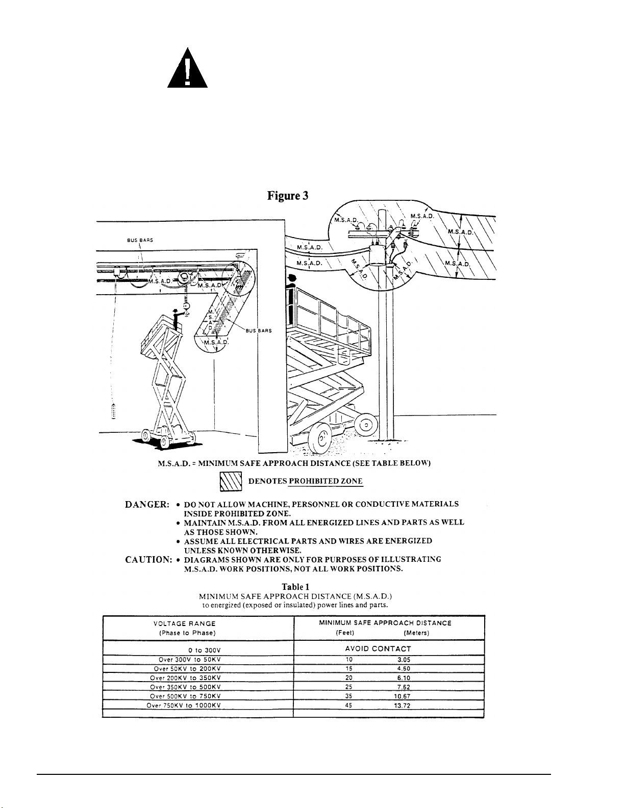
An SR is an all-metal, NON-INSULATED, aerial work-platform. Do not operate it near
ELECTRICAL conductors. Regard all conductors as being energized. Use the table and
illustration below to determine safe clearance from electrical conductors. Table 1 and Figure 3
are reprinted courtesy of Scaffold Industry Association, ANSI/SIA A92.6, page 26.
P/N 569300
Page 5

DANGER
ELECTRICAL HAZARD
SR ELEVATING WORK PLATFORMS ARE NOT
ELECTRICALLY INSULATED.
If the platform, scissors arm assembly, or any other conductive part of an SR
contacts a high-voltage electrical conductor, the result can be
DEATH
or
Be sure to allow for sag and sway in the wires and the work platform.
If an SR comes in contact with a live electrical conductor, the entire machine can
be charged. If that happens, you should remain on the machine and not contact
any other structure or object within reach. That includes the ground, adjacent
buildings, poles, and any object not a part of the SR. Such contact could make
your body a conductor to the other object creating an electrical shock hazard
resulting in
SR until you are sure the electricity has been turned off.
for persons on or near the machine.
GO NO CLOSER THAN THE MINIMUM SAFE APPROACH
DISTANCES ON THE OPPOSITE PAGE.
SERIOUS INJURY
or
DEATH
. Do not attempt to enter or leave the
SERIOUS INJURY
If an SR is in contact with a live conductor, the platform operator
others on the ground in the vicinity of the SR to
since their bodies can also form a path for electricity to ground thus creating an
electrical shock hazard with possible
Do not attempt to operate SR ground controls when the platform, scissors arm
assembly, or any other conducting part of the SR is in contact with electrical
wires or if there is an immediate danger of such contact.
Regard all conductors as energized.
Personnel working on or near an SR must be continuously aware of electrical
hazards, recognizing that
an electrical wire does occur.
SERIOUS INJURY
ELECTROCUTION
STAY AWAY
DEATH
or
and
can result if contact with
MUST
from the machine,
DEATH
warn
.
P/N
569300
i
Page 6

TABLE OF CONTENTS
XX. CHAPTER TITLE
INTRODUCTION ....................................................iii
SIGNS .............................................................iii
QUALIFIED OPERATORS..............................iii
MAINTENANCE ..............................................iii
RESPONSIBILITIES OF PARTIES .................iv
ADDITIONAL INFORMATION.........................iv
1. SAFETY ............................................................. 1 - 1
SAFE OPERATION......................................... 1 - 1
Pre-start Inspection..................................... 1 - 1
Work Place Inspection and Practices ......... 1 - 1
Electrocution ............................................... 1 - 2
Tipover & Falling Hazards........................... 1 - 2
Crushing...................................................... 1 - 2
GENERAL SAFETY PRECAUTIONS.............. 1 - 3
Personnel Precautions................................ 1 - 3
Operator General Precautions .................... 1 - 3
Mounting & Dismounting Precautions......... 1 - 3
Starting and Stopping Precautions ............. 1 - 3
Operating Precautions ................................ 1 - 3
Operator Maintenance Precautions ............ 1 - 3
Fuel Handling Precautions.......................... 1 - 3
SAFETY DECALS & PLACARDS.................... 1 - 3
2. SAFETY DEVICES............................................. 2 - 1
EMERGENCY STOP SWITCHES................... 2 - 1
ALARMS.......................................................... 2 - 1
Level Sensor ............................................... 2 - 2
Lowering ..................................................... 2 - 2
High Temperature ....................................... 2 - 2
Low Oil Pressure......................................... 2 - 2
DRIVE (reverse).......................................... 2 - 2
DRIVE (forward).......................................... 2 - 2
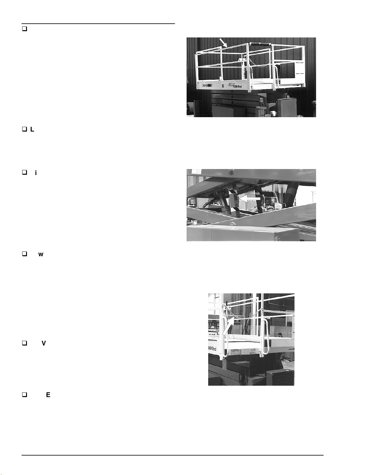
GUARDRAILS ................................................. 2 - 2
SAFETY PROP ............................................... 2 - 2
SAFETY CHAIN .............................................. 2 - 2
SWINGING GATE (option).............................. 2 - 3
SAFETY CONTROL........................................ 2 - 3
BUBBLE LEVEL (outrigger machines only) .... 2 - 3
OPERATOR HORN......................................... 2 - 3
OUTRIGGERS (option) ................................... 2 - 3
GFCI AC OUTLET (option).............................. 2 - 4
FLASHING LIGHT (option).............................. 2 - 4
LANYARD ANCHORAGE (option) .................. 2 - 4
3. SPECIFICATIONS ............................................. 3 - 1
GENERAL SPECIFICATIONS FOR
STANDARD MACHINES............................... 3 - 1
ENGINE DATA ................................................ 3 - 2
ENGINE OIL CHARTS .................................... 3 - 2
HYDRAULIC FLUID RECOMMENDED........... 3 - 2
NOMENCLATURE & SERIAL NUMBERS ......... 3 - 3
4. GAUGES............................................................ 4 - 1
WATER ........................................................... 4 - 1
AIR FILTER
AMPS .............................................................. 4 - 1
ENGINE OIL.................................................... 4 - 1
HOURS ........................................................... 4 - 2
FUEL LEVEL (option)...................................... 4 - 2
HYDRAULIC OIL LEVEL................................. 4 - 2
BUBBLE LEVEL (outrigger machines only) .... 4 - 2
COOLANT ....................................................... 4 - 2
5. AUTOMATIC SHUT-OFFS
& CIRCUIT BREAKERS .................................... 5 - 1
AUTOMATIC SHUT-OFFS.............................. 5 - 1
Level Sensor ............................................... 5 - 1
Engine Temperature ................................... 5 - 1
Engine Oil Pressure .................................... 5 - 1
Platform Height vs. Drive Speed................. 5 - 1
Parking Brakes............................................ 5 - 1
Dynamic Brakes.......................................... 5 - 1
Alternator Not Charging .............................. 5 - 2
Outriggers (option) ...................................... 5 - 2
Hydraulic Generator (option)....................... 5 - 2
.....................................................
4 - 1
CIRCUIT BREAKERS ..................................... 5 - 2
Main Breaker .............................................. 5 - 2
Hydraulic Generator Circuit Breaker (option).. 5 - 2
GFCI Outlet (option) ................................... 5 - 2
6. CONTROLS ....................................................... 6 - 1
HYDRAULIC COMPARTMENT....................... 6 - 2
BASE-CONTROL PANEL ............................... 6 - 2
PLATFORM-CONTROL BOX.......................... 6 - 4
7. OPERATION...................................................... 7 - 1
OPERATING FROM THE
BASE-CONTROL PANEL ............................ 7 - 1
Starting a Gasoline,
LP-only, or Dual-fuel Engine.................... 7 - 1
Starting a Diesel Engine ............................. 7 - 2
Raising the Platform ................................... 7 - 3
Warming the Hydraulic Oil.......................... 7 - 3
OPERATING FROM THE
PLATFORM-CONTROL BOX ...................... 7 - 4
Starting a Gasoline,
LP-only, or Dual-fuel Engine.................... 7 - 4
Starting a Diesel Engine ............................. 7 - 5
Driving......................................................... 7 - 6
Raising the Platform ................................... 7 - 7
SETTING THE OUTRIGGERS........................ 7 - 7
EXTENDING THE TWO-POSITION
PLATFORM................................................... 7 - 8
8. EMERGENCY OPERATION.............................. 8 - 1
EMERGENCY STOP ...................................... 8 - 1
EMERGENCY BLEED-DOWN........................ 8 - 1
PUSHING........................................................ 8 - 2
9. STOWING & TRANSPORTING......................... 9 - 1
STOWING....................................................... 9 - 1
TRANSPORTING............................................ 9 - 1
Trailering..................................................... 9 - 1
Securing to a Transport Vehicle ................. 9 - 3
Towing ........................................................ 9 - 3
Lifting .......................................................... 9 - 3
Pushing....................................................... 9 - 3
10. DAILY INSPECTION & MAINTENANCE......... 10 - 1
DAILY INSPECTION AND
MAINTENANCE TABLE................................ 10 - 1
PLACARDS AND DECALS
INSPECTION CHART...................................10 - 10
PLACARDS AND DECALS
INSPECTION DRAWING.............................. 10 - 11
11. TROUBLESHOOTING..................................... 11 - 1
12. OPTIONS ......................................................... 12 - 1
OPERATOR HORN.........................................12 - 1
OUTRIGGERS................................................ 12 - 1
GFCI OUTLET ................................................12 - 1
BIG PAW TIRES .............................................12 - 1
FLASHING LIGHT...........................................12 - 2
ELECTRICAL OUTLET................................... 12 - 2
SWINGING GATE........................................... 12 - 2
SPARK ARRESTOR ....................................... 12 - 3
LANYARD ANCHOR POINTS ........................12 - 3
AC GENERATOR ...........................................12 - 3
13. FIRE FIGHTING & HAZARDOUS
CHEMICAL CONTAINMENT...........................13 - 1
ANTI-FREEZE.................................................13 - 1
BATTERY, LEAD/ACID................................... 13 - 1
DIESEL FUEL .................................................13 - 1
FOAM IN TIRES..............................................13 - 1
GASOLINE...................................................... 13 - 2
HYDRAULIC OIL............................................. 13 - 2
LIQUEFIED PETROLEUM GAS .....................13 - 2
MOTOR OIL.................................................... 13 - 2
INDEX .......................................................................I - 1
WARRANTY................................. (inside back cover)
ii
P/N 569300
Page 7
X. CHAPTER NAME
INTRODUCTION
The most important chapter in this manual is “1.
SAFETY.” Take time, now, to study it closely.
The information in that chapter might save your
life or prevent serious injury.
SIGNS
T
The following two conventions are used
throughout this manual.
1. This sign
DANGER
means:
is involved
2. This sign
Attention! Become alert! Your safety
.
CAUTION
means one of two things: (1) an action, about to
be performed, is potentially hazardous and might
result in minor personal injury if not done
correctly, or (2) an action, about to be performed,
can harm the SR if not done correctly.
QUALIFIED OPERATORS
T
SR aerial platforms have built-in safety features
and have been factory tested for compliance with
Snorkel specifications and industry standards.
However, any personnel-lifting device can be
potentially dangerous in the hands of untrained
or careless operators.
Training is essential and must be performed by a
QUALIFIED person. Become proficient in
knowledge and actual operation before using the
SR on the job. You must be trained and
authorized to perform any functions of the SR.
Operation of the SR must be within the scope of
the machine specifications.
Before operating an SR you must read and
understand the operating instructions in this
manual as well as the decals, warnings, and
instructions on the machine itself.
Before operating an SR you must be
AUTHORIZED by the person in charge to do
so.
The following rules will help ensure the
safety of personnel and help prevent
needless downtime because of damaged
equipment.
1. Only TRAINED and AUTHORIZED operators
shall be permitted to operate the equipment.
2. All manufacturer’s operating instructions and
safety rules and all employers’ safety rules and
all OSHA and other government safety rules
must be strictly adhered to.
3. Repairs and adjustments shall be made only
by QUALIFIED TRAINED maintenance
personnel.
4. No modification shall be made to the
equipment without prior written consent of the
Snorkel Engineering Department.
5. You must make a prestart inspection of the SR
at the beginning of each shift. A malfunctioning
machine must not be used.
6. You must make an inspection of the work
place to locate possible hazards before operating
an SR.
DANGER
Misuse of this machine can result in DEATH
or SERIOUS INJURY.
Do not operate this equipment unless you are
TRAINED and AUTHORIZED and have read
and thoroughly understand all information
given in this Operator’s Manual and on all
DANGER and CAUTION signs on the
machine.
MAINTENANCE
T
Every person who maintains, inspects, tests, or
repairs these machines, and every person
supervising any of these functions, must be
properly trained.
This Operator’s Manual provides a daily
inspection procedure that will help you keep your
SR in good operating condition. Do not perform
other maintenance unless you are a TRAINED
mechanic, QUALIFIED to work on SR’s. Call
QUALIFIED maintenance personnel if you find
problems or malfunctions.
P/N 569300
iii
Page 8

INTRODUCTION
Information contained in this manual concerns
only current SR models, and the right is reserved
to make changes at any time without obligation.
RESPONSIBILITIES OF PARTIES
It is imperative that all owners and users of an
SR read, understand, and conform to all
applicable regulations. Ultimate compliance to
OSHA regulations is the responsibility of the
employer using the equipment.
ANSI Standard A92.6 identifies requirements of
all parties who might be involved with SelfPropelled Elevating Work Platforms.
A reprint of the “Manual of Responsibilities for
Dealers, Owners, Users, Operators, Lessors and
Lessees of ANSI/SIA A92.6-1999 Self-Propelled
Elevating Work Platforms” is available from
Snorkel dealers or from the factory upon request.
Copies are also available from:
Scaffold Industry Association, Inc.
P. O. Box 20574
Phoenix, AZ 85036-0574 USA
ADDITIONAL INFORMATION
For additional information, contact your local
dealer or write:
Snorkel International, Inc.
P.O. Box 1160
St. Joseph, MO 64502-1160 USA
1-800-255-0317
http://www.snorkelusa.com
iv
P/N 569300
Page 9
SAFE OPERATION
T
The following safety information is vitally
important for safe operation of an SR. Failure to
follow these instructions can result in personal
injury or DEATH.
Pre-start Inspection
Prior to each shift, the SR shall be given a visual
inspection and function test. (See the “DAILY
INSPECTION & MAINTENANCE” chapter in this
manual for a list of items to inspect and test.)
Do not operate an SR unless you are trained and
authorized, understand the operating
characteristics of the SR, and have inspected
and tested all functions to be sure they are in
proper working order. (See the “DAILY
INSPECTION & MAINTENANCE” chapter.)
Work Place Inspection and Practices
Do not use an SR as a ground for welding.
Ground to the work piece.
Before an SR is used, and during use, check the
area in which it is to be used for possible hazards
such as, but not limited to:
drop-offs or holes,
•
side slopes,
•
bumps and floor obstructions,
•
debris,
•
overhead obstructions and electrical
•
conductors,
hazardous locations,
•
inadequate surface and support to withstand
•
all load forces imposed by the aerial platform
in all operating configurations,
wind and weather conditions,
•
presence of unauthorized persons,
•
other possible unsafe conditions.
•
Before using the aerial platform in any hazardous
(classified) location, make certain it is approved
and of the type required by ANSI/NFPA 505 for
use in that particular location.
A recommended safety practice is to have
ground personnel, who are trained in the
operation of SR emergency controls, working in
the immediate vicinity of an elevated SR. In the
event of an emergency, they can assist the
platform operator.
1. SAFETY
1. SAFETY
1. SAFETY
When moving the platform, check the clearance
around the SR to avoid contact with structures or
other hazards. Always look in the direction of
motion.
Keep ground personnel from under the platform
when the platform is raised.
Secure all accessories, containers, tools, and
other materials in the platform to prevent them
from accidentally falling or being kicked off the
platform.
Do not engage in any form of “horseplay” or
“stunt driving” while operating an SR.
Do not permit riders on the machine anyplace
other than on the platform.
Remove all loose objects stored in or on the
machine, particularly in the platform. Remove all
objects which do not belong in or on the
machine.
When other moving equipment is in the area,
take special precautions to comply with local
regulations regarding warnings.
Never steady the platform by positioning it
against another platform.
Do not operate an SR that is not functioning
properly, or has been damaged, until the
machine has been repaired by a qualified
maintenance person.
Do not operate an SR that does not have all its
decals and placards attached and legible.
Drive the machine with care and at speeds
compatible with conditions. Use extra caution
when driving over rough ground, on slopes, and
when turning.
Know and understand the job site traffic-flow
patterns and obey the flagmen, road signs, and
signals.
Watch for bystanders and never allow anyone to
be under, or to reach through, the machine and
its equipment while operating.
P/N 569300
1 - 1
Page 10

1. SAFETY
Electrocution
SR’s are all-metal, NON-INSULATED, aerial
work-platforms. Do not operate an SR near
ELECTRICAL conductors. Regard all conductors
as being energized.
Do not operate outside during a thunderstorm.
platform before attempts are made to free the
platform using ground controls.
Do not exceed the platform capacity nor the
platform-extension capacity shown on the
capacity placards located at the entrance to the
platform and on the toeboard of the platform
extension.
Tipover & Falling Hazards
On scissor lifts, like the SR, personal fall
protection is not required by ANSI, Federal
OSHA, nor Snorkel. However, fall restraint might
be required by work regulations. If so, the user is
responsible for fitness and method of use.
The guardrail system is your fall protection. Make
sure the guardrail system is properly installed
and that all gates and fasteners are in place.
It is best not to transfer from the platform to
another structure or from the structure to the
platform, unless that is the safest way to do the
job. Judge each situation separately taking the
work environment into account. If it is necessary
to transfer from the platform to another structure
the following guidelines apply:
Where possible, place the work platform
•
next to a roof or walking structure to do
the transfer.
Transfer your anchorage from one
•
structure to another before you step
across.
Remember that you might be transferring
•
to a structure where
personal fall arrest
is required.
Do not raise the platform if the SR is on soft
ground. Raise the platform only on a firm surface
capable of withstanding all load forces imposed
by the aerial platform in all operating conditions.
Do not allow wires, cables, hoses, rope, or other
materials to trail down from the platform or be
entangled in the platform.
If you have to level an SR, that does not have
outriggers, be sure the shoring you use is strong
enough to support the weight of the SR and that
the SR wheels are chocked so that the SR
cannot be driven.
Do not jerk the controls. Move the controls slowly
and deliberately to avoid jerky and erratic
operation. Always stop the controls in the neutral,
off, position before going in the opposite
direction.
Do not use the platform for any purpose other
than to position personnel, their tools and
materials.
Do not use an SR as a crane, hoist, or jack.
Do not operate an SR in winds, or wind gusts, of
28 mph (12.5 m/s) or more.
Do not add anything to an SR that will increase
the wind loading (billboards, banners, flags, etc.).
Use the platform entrance, do not climb
•
over the guard rails.
Maintain a firm footing on the platform floor.
Climbing on the guardrails is prohibited.
Do not use ladders, planks, or other devices to
extend or increase your work position from the
platform.
Do not operate an SR from a position on trucks,
trailers, railway cars, floating vessels, scaffolds,
or similar equipment unless the application is
approved in writing by Snorkel.
If the platform or elevating assembly becomes
caught, snagged, or otherwise prevented from
normal motion by an adjacent structure, or other
obstacles, such that control reversal does not
free the platform, remove all personnel from the
1 - 2
Crushing
Always look in the direction of travel. Avoid
overhead obstructions.
Make sure the area below the platform is free of
personnel before lowering.
P/N 569300
Page 11
GENERAL SAFETY PRECAUTIONS
T
Personnel Precautions
If you encounter any suspected malfunction of
the aerial platform, or any hazard or potentially
unsafe condition relating to capacity, intended
use, or safe operation, cease operation and seek
assistance from management.
Operator General Precautions
Make sure that all protective guards, cowlings,
and doors are in place and secure.
Mounting & Dismounting Precautions
Use three points of support when getting on or
off the platform. Keep the platform clean.
Do not jump off the machine.
Do not dismount while the machine is in motion.
1. SAFETY
Do not attempt repairs unless you are trained.
Refer to manuals and experienced repair
personnel for help.
Charge batteries in a well-ventilated area free of
flame, sparks, or other hazards that might cause
fire or explosion.
Use extreme caution when removing radiator
caps. Park the machine and let it cool down
before opening a pressurized compartment.
Fuel Handling Precautions
Do not smoke or permit open flames while
fueling or near fueling operations.
Maintain control of the fuel filler nozzle when
filling the tank.
Do not fill the fuel tank to capacity. Allow room
for expansion.
Starting and Stopping Precautions
Do not start until all personnel are clearly away
from the machine.
Before leaving the operator’s station, place the
machine in the stowed position.
Remove the starter key from the
set the
the machine parked or unattended.
Do not modify an SR in any way.
Do not override any of the safety features of an
SR.
Do not exceed the side-pull forces listed on the
capacity placards located at the entrance to the
platform and on the toeboard of the platform
extension.
Limit travel speeds according to conditions. Take
into account: grade, surface, congestion,
visibility, side slope, location of personnel, and
other hazards.
Do not use your hand to search for hydraulic oil
leaks. High pressure hydraulic oil can easily cut
and penetrate your skin — a very serious injury
that requires immediate attention by a medical
specialist trained in that type of injury. Use a
piece of cardboard or wood to search for
hydraulic oil leaks.
BATTERY
Operating Precautions
Operator Maintenance Precautions
switch to OFF when leaving
KEY
switch and
Clean up spilled fuel immediately.
Tighten the fuel tank cap securely. If the fuel cap
is lost, replace it with an approved cap from
Snorkel. Use of a non-approved cap without
proper venting may result in pressurization of the
tank.
Never use fuel for cleaning purposes.
For diesel engines, use the correct fuel grade for
the operating season.
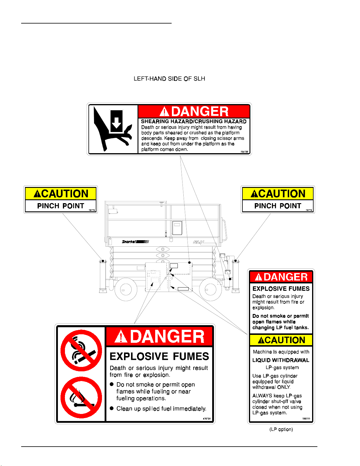
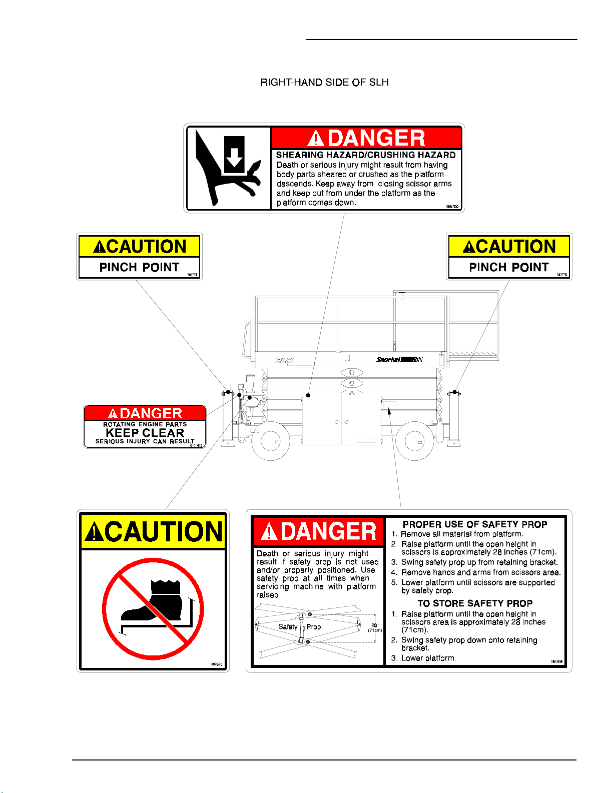
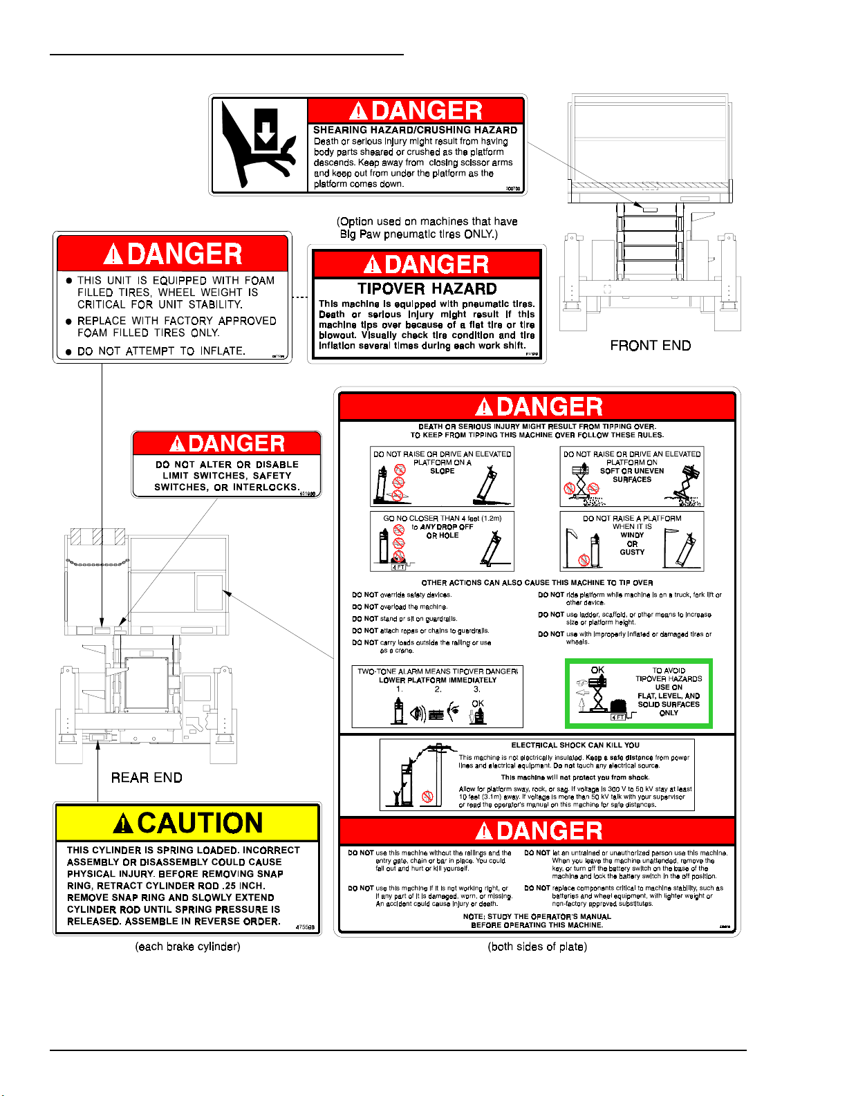
SAFETY DECALS & PLACARDS
T
There are several safety decals and placards on
an SR. Their locations and descriptions are
shown in this section. Take time to study them.
Be sure that all the safety decals and placards
on the SR are legible. Clean or replace them if
you cannot read the words or see the pictures.
Clean with soap & water and a soft cloth. Do not
use solvents.
You must replace a decal or placard if it is
damaged, missing, or cannot be read. If it is on a
part that is replaced, make sure a new decal or
placard is installed on the replaced part. See
your Snorkel dealer for new decals and placards.
Refer to the PLACARDS AND DECALS
INSPECTION CHART and DRAWING in the
“DAILY INSPECTION AND MAINTENANCE”
chapter for part numbers, location, and required
quantities of all placards and decals.
P/N 569300
1 - 3
Page 12
1. SAFETY
Refer to the PLACARDS AND DECALS INSPECTION CHART and DRAWING in the
“DAILY INSPECTION AND MAINTENANCE” chapter for part numbers, locations, and
required quantities of all placards and decals.
1 - 4
P/N 569300
Page 13
1. SAFETY
P/N 569300
1 - 5
Page 14
1. SAFETY
1 - 6
P/N 569300
Page 15
2. SAFETY DEVICES
2. SAFETY DEVICES
The devices listed in this chapter are safety
devices. They are on an SR to increase safety in
the work place for both the operator and other
people near the machine. Do not by-pass,
disable, modify, or ignore any of these devices.
Check them carefully at the start of each work
shift to see that they are in working order (see
“DAILY INSPECTION & MAINTENANCE”
chapter). If any is found to be defective, remove
the SR from service immediately until a qualified
service technician can make repairs.
EMERGENCY STOP SWITCHES
T
T
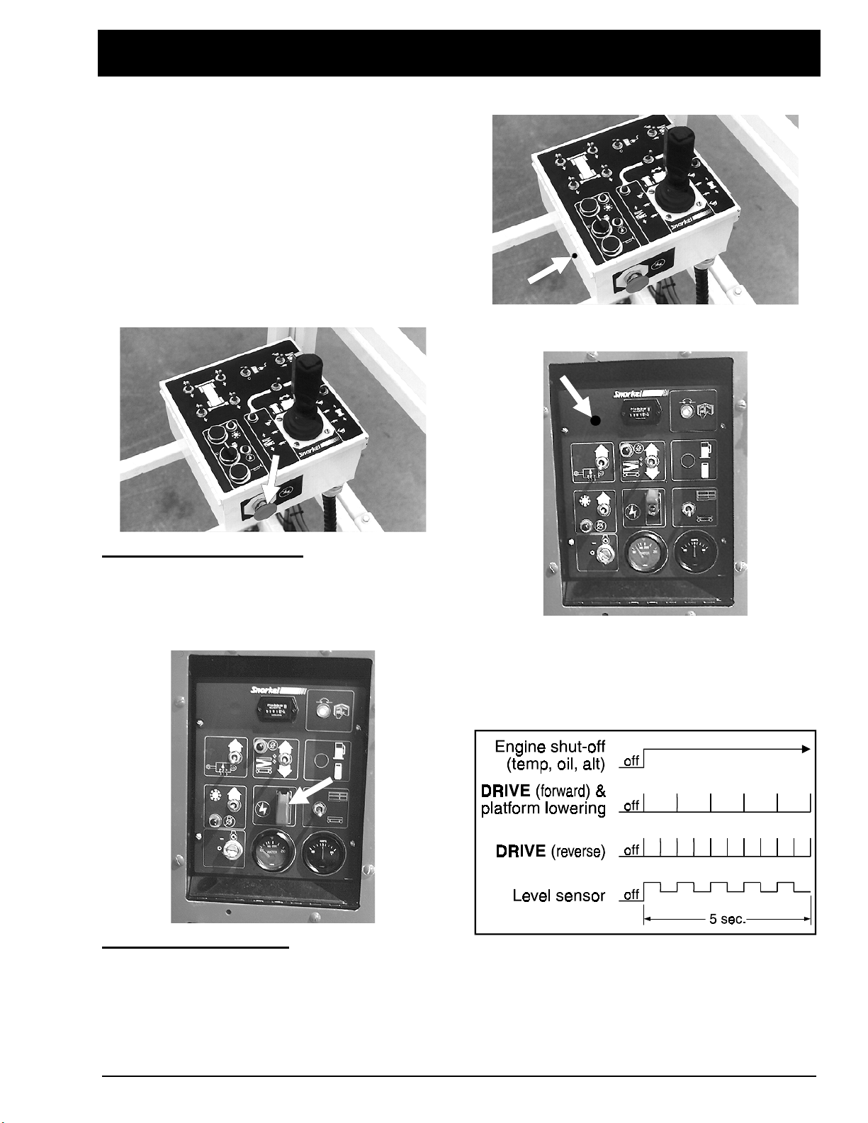
ALARMS
There are two alarms on an SR. One is located
in the platform-control box,
At the platform-control box:
red
EMERGENCY STOP
machine stops, the engine turns off, and nothing
moves. This switch must be out (on) to control
the SR from the platform (turn the switch
clockwise and it will pop out.
At the base-control panel:
EMERGENCY STOP
time, under any conditions, and the entire
machine stops, the engine turns off, and nothing
moves. The
up for anything on the SR to work.
EMERGENCY STOP
switch cover down, at any
Press the large
button in and the entire
Press the red
switch must be
the other is located in the base-control box. The
alarms are connected in parallel, they both emit
the same pattern of sound at the same time. The
different alarm sound patterns are shown in the
table immediately below and discussed below the
table.
The high-temperature, low oil-pressure, and
alternator not-charging alarms are each a
continuous tone. The
platform-lowering alarms beep at one beep per
second.
second. The level sensor alarm is a high-low
warbling sound.
DRIVE
DRIVE
(reverse) beeps at two beeps per
(forward) and the
P/N 569300
2 - 1
Page 16
2. SAFETY DEVICES
Level Sensor
The level sensor alarm warns the SR operator
that the SR is not level. If the tilt continues to
increase, the SR will eventually tip over. When
you hear this alarm, immediately lower the
platform completely down. When the platform is
completely down, determine and correct the
cause of the tilt before raising the platform again.
NOTE: While the alarm is sounding it is not
possible to drive the SR nor raise the
platform.
T
GUARDRAILS
Lowering
The lowering alarm warns people near an SR
that the platform is coming down and the scissor
arm assembly is closing.
High Temperature
The high-temperature alarm warns you that the
engine is overheating. When the alarm sounds
you should immediately lower the platform
completely down then turn the engine off until the
condition that caused the overheating has been
corrected. (See “AUTOMATIC SHUT-OFFS &
CIRCUIT BREAKERS” chapter for more
information.)
Low Oil Pressure
The low pressure alarm warns you that the
engine oil pressure is near the lower limit for safe
operation of the engine. When the alarm sounds
you should immediately lower the platform
completely down then turn the engine off until the
condition that caused the low oil pressure has
been corrected. (See “AUTOMATIC SHUT-OFFS
& CIRCUIT BREAKERS” chapter for more
information.)
The guardrails help protect you from falling off
the platform. Be sure the guardrails are properly
installed and that the safety chain (or gate) and
fasteners are in place.
T
SAFETY PROP
Always raise the safety prop then lower the
scissor-arm assembly onto the safety prop
before reaching into the scissor-arm assembly
for any reason.
T
SAFETY CHAIN
DRIVE (reverse)
The
DRIVE
SR is traveling backward along the ground. This
alarm beeps twice as fast as the
(forward) alarm.
DRIVE (forward)
The
DRIVE
SR is traveling forward along the ground. This
alarm beeps half as fast as the
alarm.
2 - 2
(reverse) alarm alerts people that the
DRIVE
(forward) alarm alerts people that the
DRIVE
(reverse)
The safety chain should be closed at all times
except when someone is entering or leaving the
platform.
P/N 569300
Page 17
2. SAFETY DEVICES
SWINGING GATE
T
The swinging gate should be closed at all times
except when someone is entering or leaving the
platform.
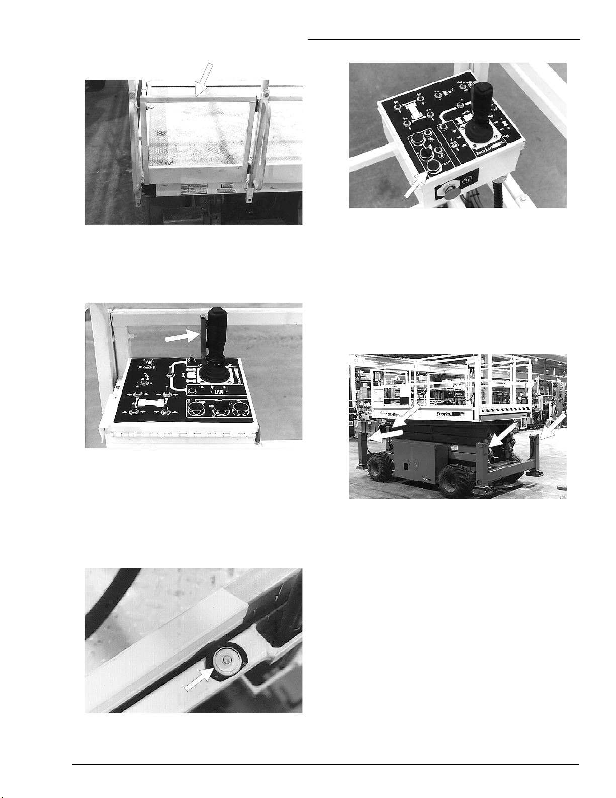
SAFETY CONTROL
T
(option)
OPERATOR HORN
T
The operator horn is used primarily to get the
attention of people on the ground when you are
working aloft. For the horn to work the following
switches, on the base-control panel, must be set
as indicated:
MAIN POWER
EMERGENCY STOP
SELECTOR
OUTRIGGERS
T
.................ON
......................PLATFORM
(option)
.......on (up)
(option)
The safety control must be squeezed and held to
activate the joystick. The safety control prevents
the joystick from moving the platform if
something accidentally pushes the joystick. Do
not disable the safety control in any way.
BUBBLE LEVEL
T
(outrigger machines
only)
See the “GAUGES” chapter for a discussion of
the bubble level.
The outrigger controls are on the upper left side
of the platform-control box.
The outriggers are used to level the SR (for
complete outrigger operating procedures see the
“OPERATION” chapter).
NOTE: The SR must be on a firm surface
capable of withstanding all load forces
imposed by the aerial platform in all operation
conditions before the outriggers are used.
P/N 569300
2 - 3
Page 18
2. SAFETY DEVICES
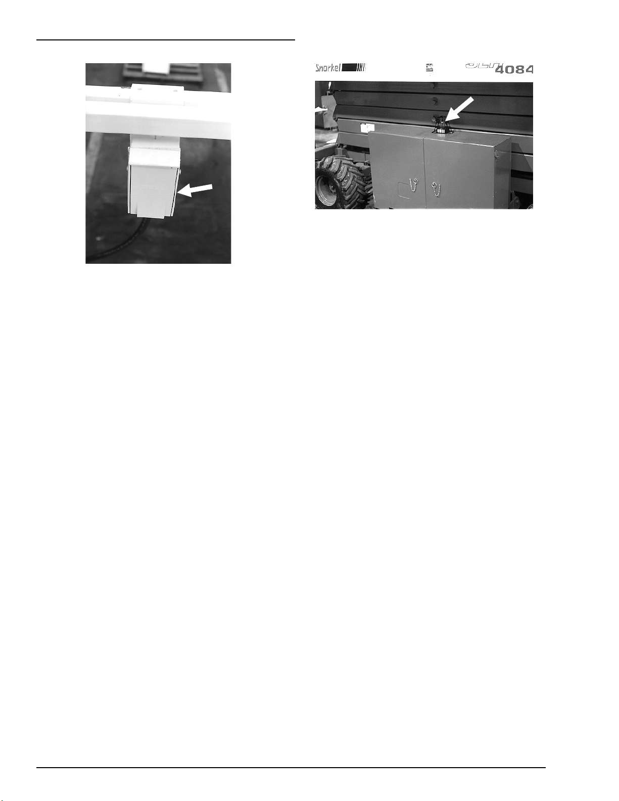
GFCI AC OUTLET
T
The GFCI (ground fault circuit interrupt) is
located under the platform-control box. To use
the outlet set the
NOTE: If the SR does not have the ac
generator option, connect a source of power
to the GFCI plug at the base-control panel.
The GFCI will protect against short circuits to
ground. When there is a short to ground the
GFCI will shut off power to the outlet.
To reset the outlet:
Unplug the equipment being used.
Press the
This should restore power to the outlet. If it does
not, set the
refer the problem to a trained service technician.
RESET
AC OUTLET SWITCH
(option)
AC OUTLET SWITCH
button on the GFCI outlet.
to off (O) and
to on (-).
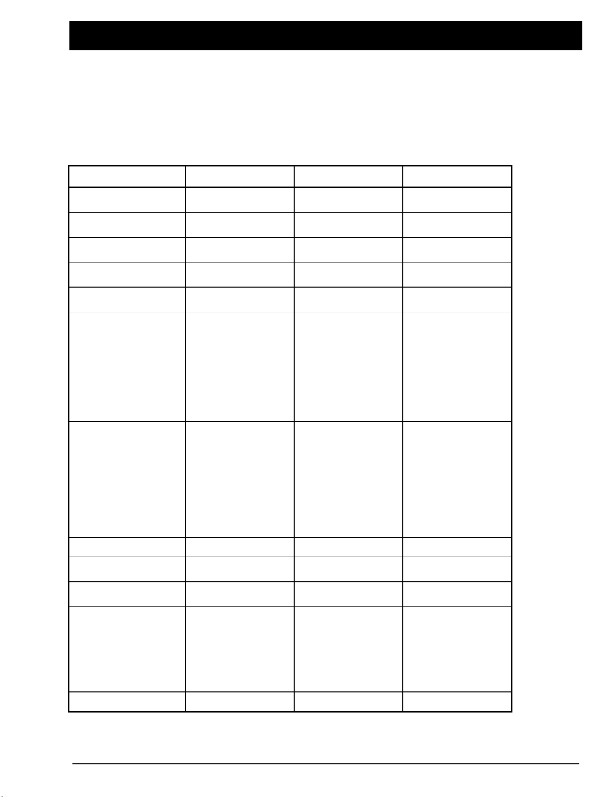
FLASHING LIGHT
T
The flashing light alerts people that the SR is
present and that the SR is moving. The light
flashes at about one flash per second any time
the SR engine is running. There is no ON/OFF
switch for the flashing light, it cannot be turned
off while the SR is running.
LANYARD ANCHOR POINTS
T
There are four anchors on the floor of the
platform, one at the front of the roll-out deck, one
at the back of the platform, and one on each side
of the platform.
NOTE: These anchors are not for lifting or
tying down the machine.
You should attach your fall protection to the
anchors if work rules require it.
(option)
(option)
2 - 4
P/N 569300
Page 19
3. SPECIFICATIONS
3. SPECIFICATIONS
Snorkelift SR series machines are scissorsupported elevating work-platforms built to
conform to the following standards:
OSHA Paragraph 1910.67 Title 29,
C.F.R.Vehicle-Mounted Elevating and Rotating
Work Platforms - Labor.
GENERAL SPECIFICATIONS FOR STANDARD MACHINES
T
OSHA Paragraph 1926.556 Title 29, C.F.R.,
Aerial Lifts - Construction. ANSI Standard A92.6,
Self-Propelled Elevating Work Platforms.
CSA Standard CAN 3-B354.3-M82, Self
Propelled Elevating Work Platforms for use as
“Off Slab” Units.
SR: SR2584 SR3284 SR4084
Weight
Max. single wheel
load
Ground pressure
(max)
Width
Length
Height:
working
6280 lbs.
(2855 kg)
3332 lbs.
1511 kg
34 psi
2.4 kg/cm
84 in.
(213 cm)
137 in.
(348 cm)
31 ft.
(9.4 m)
7650 lbs.
(3477 kg)
3560 lbs.
1615 kg
2
39 psi
2.7 kg/cm
84 in.
(213 cm)
137 in.
(348 cm)
38 ft.
(11.6 m)
2
8720 lbs.
(3964 kg)
3788 lbs.
1718 kg
45 psi
3.2 kg/cm
84 in.
(213 cm)
149 in.
(378 cm)
46 ft.
(14 m)
2
raised
lowered
Platform:
driveable ht.
size* in.
(cm)
capacity
Drive wheels
Rear axle
Tires in.
(cm)
Speed:
Max. drive
25 ft.
(7.6 m)
47 in.
(119 cm)
FULL
72x120
(183x305)
1750 lbs.
795 kg)
444
Driven
Articulated
26x12
66x30.5
2.2 mph
(1 km/h)
32 ft.
(9.8 m)
53.5 in.
(136 cm)
FULL
72x120
(183x305)
1250 lbs.
(568 kg)
Driven
Articulated
26x12
66x30.5
2.2 mph
(1 km/h)
40 ft.
(12.2 m)
60 in.
(152 cm)
32 ft.
(9.8 m)
72x120
(183x305)
750 lbs.
(341 kg)
Driven
Articulated
26x12
66x30.5
2.2 mph
(1 km/h)
Max. raise
Lower
Gradeability
22 sec
25 sec
32% 32% 30%
* Four foot (1.8 m) platform-extension retracted.
P/N 569300
30 sec
40 sec
45 sec
40 sec
3 - 1
Page 20
3. SPECIFICATIONS
ENGINE DATA
T
ENGINE MAKE KUBOTA
MODEL WG750-G D905-B V800-B
FUEL gasoline LPG diesel no. 2-D
FUEL GRADE
COOLANT 50% water + 50% ethylene glycol
unleaded
85 octane
(motor method)
Do not use
gasoline blended
with methyl
alcohol
.
HD5
Gas Processors
Association
Standard 2140
Category: special
duty propane
ASTM no. 2-D
ASTM D975
cetane no. > 44
(For operating temp. below 32°F (0°C)
use “winterized” no. 2-D.)
OPERATING
TEMPERATURE
OIL CAPACITY 3.5 qt USA
OIL GRADE API: SF, SF/CD API:CC/CD/CE
OIL WEIGHT see chart below
RUNNING TIME
(one tank of fuel)
ENGINE OIL CHARTS
T
WG750-G
Ambient temperature
above 77°F (25°C)
32°F to 77°F
(0°C) to (25°C)
0°F to 32°F
(-17°C) to (0°C)
180°F - 205°F(82°C - 96°C)
5.2 qt USA
(3.25 liters)
A full tank of gasoline, or diesel, will last an entire eight hour shift, under normal
working conditions. It normally takes two tanks of LPG per eight hour shift.
D905-B and V800-B
Engine oil weight
SAE30 or 10W30
SAE20 or 10W30
SAE10W or 10W30
Ambient temperature
above 77°F (25°C)
32°F to 77°F
(0°C) to (25°C)
below 32°F (0°C)
(5.1 liters)
Engine oil weight
SAE30 or 10W30
10W40
SAE20 or 10W30
10W40
SAE10W or 10W30
10W40
4.2 qt USA
(4.0 liters)
HYDRAULIC FLUID RECOMMENDED
T
Above 10°F (13°C) use Mobil DTE-13M (ISO VG32)
Below 10°F (13°C) use Mobil DTE-11 (ISO VG15)
3 - 2
P/N 569300
Page 21
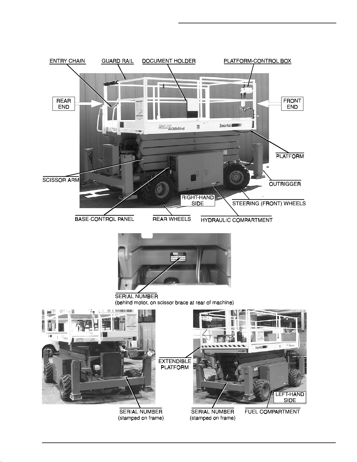
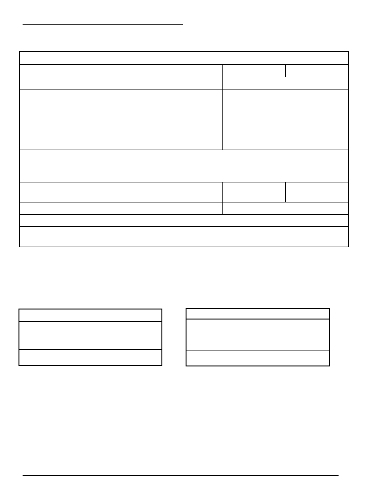
NOMENCLATURE & SERIAL-NUMBERS
)
T
3. SPECIFICATIONS
P/N 569300
3 - 3 (3 - 4 blank
3 - 3
Page 22

Page 23
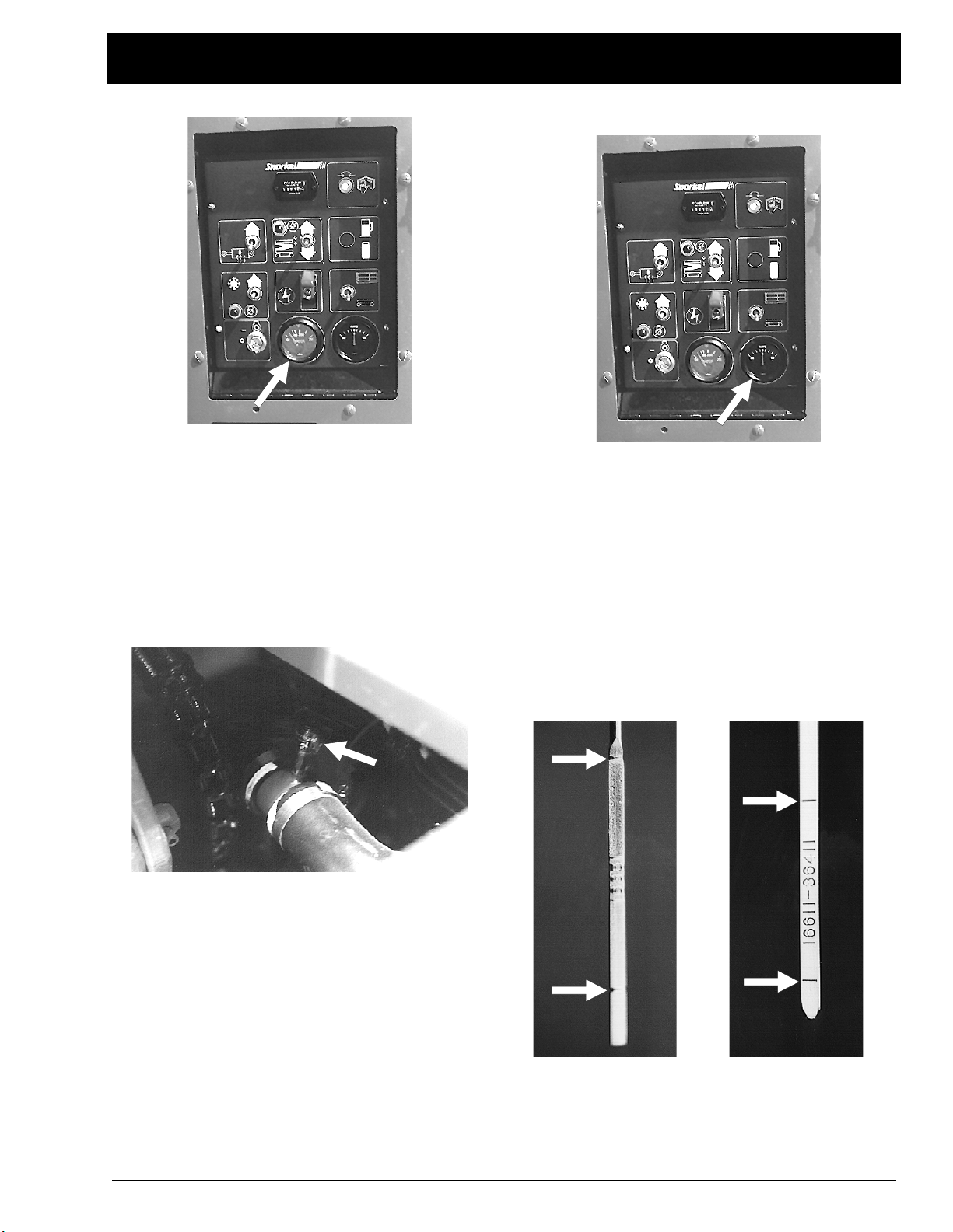
WATER
T
T
AMPS
4. GAUGES
4. GAUGES
The
WATER
control panel. It shows the temperature of the
water-antifreeze mixture in the engine block. The
typical operating-temperature range for Kubota
engines is 180°F to 205°F (82°C to 96°C), both
diesel and gasoline. (See the “AUTOMATIC
SHUT-OFFS & CIRCUIT BREAKERS “ chapter
for more information.)
T
AIR FILTER
The air filter gauge is located between the air
filter and the intake manifold. The gauge
measures the vacuum (air pressure) between the
intake manifold and the air filter. As the filter
clogs, the vacuum increases (pressure drops).
As the vacuum increases, a red indicator raises
toward the clear area of the gauge. When you
can see the indicator in the clear area of the
gauge, it’s time to change the air filter.
The indicator stays at its highest setting, it does
not go to the bottom of the gauge when the
engine is turned off or the filter changed. After
the filter is changed, press the small reset button
to reset the indicator to the bottom of the gauge.
gauge is located on the base-
The
AMPS
from the alternator to the battery. When the
engine is running, the needle in the
should not be to the left of “0.” Under normal
operating conditions, after the engine has been
running for a few minutes, the
should read “0.”
T
ENGINE OIL
GASOLINE DIESEL
Engine oil level is measured with a dipstick. Oil
capacities given in the “SPECIFICATIONS”
chapter are approximate. True values will vary
from machine to machine due to slight variations
or modifications during production. The oil
dipstick is the only way to accurately gauge if the
engine oil level is correct. Engine oil level should
gauge shows the electric current
AMPS
AMPS
gauge
gauge
P/N 569300
4 - 1
Page 24

4. GAUGES
always be between the lines on the dipstick —
never above the top line or below the bottom line.
HOURS
T
HYDRAULIC OIL LEVEL
T
The hydraulic-oil level gauge is on the side of
the hydraulic oil tank. It shows the actual level of
oil inside the tank. Read it only when the platform
is completely down. Otherwise, the lift cylinders
become large reservoirs for hydraulic oil and the
oil level in the tank will be low. The oil level
should be within ± 0.25 inches (± 6.4 mm) of the
line.
HOURS
The
It accumulates time only when the engine is
running. The
SR-qualified service technician uses it to tell
when it is time for the periodic maintenance listed
in the Maintenance Manual.
FUEL LEVEL
T
LPG tanks have two fuel gauges (1) (2) on top.
One measures correctly when the tank is
standing on end (
measures correctly when the tank is laying down
HORIZONTAL
(
tank. SR tanks are mounted horizontally.
Therefore, you should read the
scale (2).
gauge is basically an electric clock.
HOURS
gauge cannot be reset. An
(option)
VERTICAL
). Both read in fractions-of-a-full-
) the other
HORIZONTAL
BUBBLE LEVEL
T
A bubble level is located on the platform side rail,
below the platform-control box. Watch the bubble
level while you set the outriggers. Lower the
outriggers, one at a time, just enough to center
the bubble in the circle on top of the gauge.
When the bubble is centered the platform is level
and can safely be raised.
COOLANT
T
The engine coolant reservoir is on the front of the
step weldment. When the engine is at operating
temperature the coolant should be at the HOT
line. When the engine is cold there should be
about one inch (2.54 cm) of coolant in the bottom
of the reservoir.
(outrigger machines only)
4 - 2
P/N 569300
Page 25

5. AUTOMATIC SHUT-OFFS
5. AUTOMATIC SHUT-OFFS
& CIRCUIT BREAKERS
AUTOMATIC SHUT-OFFS
T
Level Sensor
When the level sensor alarm sounds, automatic
interlocks make it impossible to drive the SR or
raise the platform. For more complete
information see the “Level Sensor” subsection of
the “SAFETY DEVICES “ chapter.
Engine Temperature
the engine shuts off. The engine will restart with
low pressure but it will only run a few seconds
before it automatically shuts off again.
Platform Height vs. Drive Speed
When the platform is over seven feet (2.1 m)
above the ground the drive speed is limited to the
slowest speed and the lift speed is also limited to
the slowest speed.
Parking Brakes
There is a temperature sensor in the engine. It
measures the temperature of the antifreezewater mixture as the mixture leaves the top of
the radiator and enters the top of the engine. If
the temperature reaches 210°F (99°C) an alarm
sounds. If the temperature continues to rise, the
engine shuts off when the temperature reaches
230°F (110°C). The engine will not restart until
the temperature drops below 210°F (99°C).
Engine Oil Pressure
When the
neutral position the SR parking brakes are
automatically set. The brakes automatically
release when you move the
CONTROLLER
Dynamic Brakes
When you drive an SR down a slope, if the SR
begins to coast (outrun the drive motors) the
hydraulic system “senses” the coasting condition.
The hydraulic drive motors then become
hydraulic brakes and the SR is slowed. This
action prevents SRs from speeding down
grades.
JOYSTICK CONTROLLER
JOYSTICK
to drive.
is in the
There is an oil pressure sensor in the engine. It
measures the engine oil pressure at the oil filter.
If the pressure falls below a safe operating value
P/N 569300
5 - 1
Page 26

5. AUTOMATIC SHUT-OFFS
Alternator Not Charging
problem to a qualified trained service technician
for repair.
Hydraulic Generator Circuit Breaker
(option)
SRs that have hydraulically powered ac
generators have a circuit breaker at the
generator to protect the generator from
overloads. If the breaker trips (pops out) do the
following:
When the fan belt breaks, or the alternator
output falls below a safe level for other reasons,
the engine automatically shuts off and an alarm
sounds. As long as the SR battery is charged
you can lower the platform, in the usual way,
from the platform-control box or the base-control
panel without the engine running.
Outriggers
The SR cannot be driven unless the outriggers
are completely up. If you have just raised the
outriggers but the SR will not drive, double check
to be sure all four outriggers are completely up.
Hydraulic Generator
The SR cannot be driven nor can the platform be
raised while the 120 V ac, hydraulically powered,
generator is running (the
GENERATOR/MACHINE
GENERATOR).
(option)
(option)
switch is set to
Turn the
MACHINE.
Disconnect whatever is plugged into the ac
outlet on the platform.
After the breaker has had time to cool off,
push it back in then attempt to reuse the
generator in the normal way.
If the breaker trips a second time, refer the
problem to a qualified trained service technician.
GFCI Outlet
MACHINE/GENERATOR
(option)
switch to
T
CIRCUIT BREAKERS
Main Breaker
There is only one circuit breaker, on a standard
SR, that is accessible to the operator. Its
purpose is to protect the electrical circuits from
electrical overloads. When the circuit breaker
trips (pops out) push it back in then attempt to
use the SR. If the circuit breaker trips a second
time, take the SR out of service and refer the
5 - 2
The GFCI (ground fault circuit interrupt) will
protect against short circuits to ground. When
there is a short to ground the GFCI will shut off
power to the outlet.
To reset the outlet:
Unplug the equipment being used.
Press the
This should restore power to the outlet. If it does
not, set the
refer the problem to a trained service technician.
NOTE: The GFCI does not protect against
electrical overloads.
RESET
AC OUTLET SWITCH
button on the GFCI outlet.
to off (O) and
P/N 569300
Page 27

6. CONTROLS
6. CONTROLS
6. CONTROLS
This chapter explains what each control does.
This chapter does not explain how to use the
controls to produce useful work, refer to the
“OPERATION” chapter for that, after you have
read this chapter.
For optional-equipment controls, see the
“OPTIONS” chapter. The only optionalequipment controls discussed in this chapter are
the controls for: diesel engines, dual-fuel
engines, LP-only engines, and outriggers.
See the “EMERGENCY OPERATION” chapter
for the location of the emergency bleed down
control and for correct emergency bleed down
procedures.
The main operating functions of an SR can be
controlled from the base-control panel (1) or the
platform-control box (2).
P/N 569300
6 - 1
Page 28

6. CONTROLS
HYDRAULIC COMPARTMENT
T
BATTERY
for the engine to start. When the BATTERY
switch is OFF the positive side of the SR battery
is disconnected from the electrical system. Lock
this switch OFF when the SR is left unattended.
: The BATTERY switch must be ON
3.
GLOW-PLUG INDICATOR LIGHT
engines only): This light will be on while the glow
plugs are on. Wait, about 10 seconds for the light
to go out before you try to start a diesel.
4.
CHOKE
choke switch up anytime you start a gasoline
engine that is at ambient air temperature (a
“cold” engine).
(gasoline engines only): Hold the
(diesel
BASE-CONTROL PANEL
T
Controls for operating an SR from the ground are
located on the right side of the machine on the
rear of the hydraulic compartment.
NOTE: The number of each control below
corresponds to the control’s call-out on the
next page.
1.
EMERGENCY STOP
cover down, at any time, under any conditions,
and the entire machine stops — the engine turns
off and nothing moves. This switch must be up
for anything on the machine to work.
2.
KEY SWITCH
automobile ignition switch. Hold the key at the
start symbol (extreme clockwise position) until
the engine starts then release it to the on
position (bar symbol).
Turn the key to off (O) if the platform is to stay in
one position for a long time. That will turn the
engine off and save fuel.
3.
CHOKE INDICATOR LIGHT
engines only): This light will be lit while you
choke the engine (see
: This switch works like an
: Press the red switch-
(gasoline
CHOKE
below).
4.
GLOW PLUG
momentary contact switch. Press it up then
release it just before you start a diesel engine
that is at ambient air temperature (a “cold”
engine). This action automatically causes glow
plugs to come on for 10 seconds to warm the
inside top of each cylinder, thus aiding
combustion.
5.
HYDRAULIC OIL WARM-UP
ambient air temperature is below 50°F (10°C)
and SR movement is sluggish because of cold
hydraulic oil, turn the warm-up switch on (up) for
5 to 10 minutes or until the hydraulic oil tank is
warm to the touch then turn the switch off
(down).
For the warm-up system to work, the engine
must be running.
While the warm-up system is on, do not attempt
to move the SR in any way.
6.
LIFT INDICATOR LIGHT
raised only when this light is lit. When this light is
not lit the platform will not rise because: the
platform is not level, the outriggers are not
properly set, or the articulating axles are not all
set.
7.
PLATFORM LIFT/LOWER
up causes the platform to rise. Pushing this
switch down causes the platform to lower.
8.
engine set the FUEL switch to gasoline (up) or
LP gas (down) depending on which you want to
use. If you select LP gas, be sure to open the
valve on top the LP gas tank.
9.
down for the base-control panel to work. Must be
up for the platform-control box to work.
(option): Before starting a dual-fuel
FUEL
BASE/PLATFORM SELECTOR
(diesel engines only): This is a
: When the
: The platform can be
: Holding this switch
: Must be
6 - 2
P/N 569300
Page 29

BASE-CONTROL PANEL
6. CONTROLS
P/N 569300
6 - 3
Page 30

6. CONTROLS
PLATFORM-CONTROL BOX
T
Controls for operating an SR from the platform
are located on the platform-control box.
NOTE: The number of each control below
corresponds to the control’s call-out on the
next page.
EMERGENCY STOP
1.
at any time, under any conditions, and the entire
machine stops — the engine turns off and
nothing moves. This switch must be out (on) to
start and run the SR from the platform-control
box, turn the switch clockwise and it will pop out
(on). Press the switch in (off) if the platform is to
stay in one position for a long time. That will turn
the engine off and save fuel.
NOTE: The EMERGENCY STOP switch on
the base-control panel overrides the one on
the platform-control box. If the one on the
base-control panel is off the SR will not start
or run, it does not make any difference
whether the one on the platform-control box is
on or off.
START
2.
the engine. As soon as the engine starts, release
the switch.
CHOKE
3.
hold the switch in anytime you start a gasoline
engine that is at ambient air temperature (a
“cold” engine).
GLOW PLUG
3.
momentary contact switch. Press it up then
release it just before you start a diesel engine
that is at ambient air temperature (a “cold”
engine). This action automatically causes glow
plugs to come on for 10 seconds to warm the
inside top of each cylinder, thus aiding
combustion.
CHOKE INDICATOR LIGHT
4.
engines only): This light will be lit while you
choke the engine.
GLOW PLUG INDICATOR LIGHT
4.
engines only): This light will be on while the glow
plugs are on. Wait for the light to go out before
you try to start a diesel.
SAFETY CONTROL
5.
must be squeezed against the JOYSTICK
CONTROLLER to activate the JOYSTICK
: Press and hold the switch in to start
(gasoline engines only): Press and
(diesel engines only): This is a
: Press the red button in
(gasoline
(diesel
The SAFETY CONTROL
CONTROLLER. If the SAFETY CONTROL is not
squeezed the JOYSTICK CONTROLLER is
inoperative.
JOYSTICK CONTROLLER
6.
SELECTOR is set to the left (lift function),
pushing the JOYSTICK CONTROLLER forward
causes the platform to rise, pulling the
JOYSTICK CONTROLLER backward causes the
platform to lower. If the LIFT/DRIVE SELECTOR
is set to the right (drive function), pushing the
JOYSTICK CONTROLLER forward causes the
SR to move forward, pulling the JOYSTICK
CONTROLLER backward causes the SR to
move backward. The further you push or pull the
controller the faster the motion (except
lowering—it occurs at one speed only).
NOTE: Squeeze the SAFETY CONTROL
anytime you use the JOYSTICK
CONTROLLER.
STEERING
7.
JOYSTICK CONTROLLER turns the front
wheels left or right depending upon which side of
the switch you press.
NOTE: The wheels do not return to straight
ahead, after a turn, the way automobile
wheels do. You must use the STEERING
switch to straighten the wheels after a turn.
LIFT/DRIVE SELECTOR
8.
set to the left the JOYSTICK CONTROLLER
becomes a lift/lower controller to raise or lower
the platform. When this switch is set to the right
the JOYSTICK CONTROLLER becomes a drive
controller to drive the SR forward or backward.
The SR will not drive and lift at the same time.
SPEED
9.
you are working in close quarters or if you are
new to the machine. Setting the switch to rabbit
(fast) doubles the top speed of the SR.
AC OUTLET SWITCH
10.
on/off switch for the 120 V ac hydraulically
powered generator. When the switch is on, the
outlet box at the platform is energized.
LIFT INDICATOR LIGHT
11.
be raised only when this light is lit. When this
light is not lit the platform will not rise because:
the platform is not level, the outriggers are not
properly set, or the articulating axles are not all
set.
OUTRIGGERS
12.
one of the outriggers. Pull a switch backward to
lower an outrigger, push it forward to raise the
outrigger.
: The rocker switch on top of the
: Set the switch to turtle (slow) when
: Each switch corresponds to
: If the LIFT/DRIVE
: When this switch is
(option): This is an
: The platform can
6 - 4
P/N 569300
Page 31

PLATFORM-CONTROL BOX
)
6. CONTROLS
P/N 569300
6 - 5 (6 - 6 blank
6 - 5
Page 32

Page 33

7. OPERATION
7. OPERATION
This chapter explains how to start and run an SR
that has either a gasoline or diesel engine.
Starting a gasoline engine that is set up to burn
LP-only or dual-fuel is also discussed in this
chapter.
To use this chapter, first decide whether you will
be starting and operating the SR from the basecontrol panel or the platform-control box. Go to
the section entitled “OPERATING FROM THE
BASE-CONTROL BOX” if you intend to start and
run the SR from the base-control panel. Go to
“OPERATING FROM THE PLATFORMCONTROL BOX” if you intend to start and run
the SR from the platform.
After you have made the “base-control / platformcontrol” decision you need to know whether the
SR has a gasoline or diesel engine. If it has a
“gasoline” engine you further need to know
whether it is set up to burn LP-only, or dual-fuel
(LP or gasoline). If it is set up to burn dual-fuel
you have to decide whether to burn gasoline or
LP. The simplest way to tell what kind of engine
set up you have is to look in the fuel
compartment on the left side of the SR -- open
both fuel compartment doors.
OPERATING FROM THE BASE-
T
CONTROL PANEL
Starting a Gasoline, LP-only, or Dual-fuel
Engine
To start a gasoline, LP-only, or dual-fuel (LP &
gasoline) engine from the base-control panel do
the following:
1
1. Set the
BATTERY
switch (1) to ON.
1. If the only fuel source you see there is a
tank labeled GASOLINE FUEL, the SR has a
gasoline engine set up to burn gasoline.
2. If the only fuel source you see is a tank
labeled DIESEL FUEL, the SR has a diesel
engine.
3. If the only fuel source you see is one or
more LP tanks, the SR has a special gasoline
engine set up to burn LP-only.
4. If you see a GASOLINE FUEL tank and
one or more LP tanks, the SR has a special
gasoline engine set up to burn either gasoline
or LP.
Once you have determined the type of engine
installed and the type of fuel you will burn you
should go to the corresponding subsection that
explains how to start that type engine. Read the
“TABLE OF CONTENTS” at the front of this
manual to see how the different sections and
subsections of this chapter are arranged.
2. Set the
(up).
3. Set the
(3) to base (down).
EMERGENCY STOP
BASE/PLATFORM SELECTOR
switch (2) to on
switch
P/N 569300
7 - 1
Page 34

7. OPERATION
Starting a Diesel Engine
To start a diesel engine from the base-control
panel do the following:
4
1
4. For LP operation
(4) on top of the LP tank (unscrew
counterclockwise until it stops).
5. For a dual-fuel engine
(9) to LP fuel (5) or gasoline fuel (6), depending
on which you want to use.
: Completely open the valve
: Set the
FUEL
switch
1. Set the
2. Set the
(up).
3. Set the
(3) to base.
BATTERY
EMERGENCY STOP
BASE/PLATFORM SELECTOR
switch (1) to ON.
switch (2) to on
switch
6. If the engine is cold, press and hold the
CHOKE
7. Turn the key (8) to start and hold it there until
the engine starts or for 20 seconds, whichever
comes first. When the engine starts, release both
the key (8) and the
switch (7) during the next step.
CHOKE
switch (7).
CAUTION
If the engine does not start in 20 seconds, turn
the key (8) to off and release the
(7) then wait 60 seconds before trying to start the
engine again.
7 - 2
CHOKE
switch
4. Turn the key (4) to on -- do not turn the key (4)
to start.
5. If the engine is at ambient temperature,
momentarily press the
This action will automatically turn the glow-plugs,
in the engine, on for 10 seconds. A light (6) will
automatically come on to indicate that the glowplugs are on.
GLOW-PLUG
switch (5).
P/N 569300
Page 35

CAUTION
If the engine does not start in 20 seconds, turn
the key (4) to off then wait 60 seconds before
trying to start the engine again with the
PLUG
6. When the light (6) goes out, turn the key (4) to
start and hold it there until the engine starts or
for 20 seconds, whichever comes first. When the
engine starts, release the key (4).
switch (5) and key (6).
Raising the Platform
GLOW-
7. OPERATION
Warming the Hydraulic Oil
When SR movement is sluggish due to low
ambient temperature -- below about 50°F (10°C)
-- do the following:
The platform,
be raised above 32 feet (9.8 m) if the outriggers
are not set. (See “SETTING THE
OUTRIGGERS” below in this chapter.
To raise the platform from the base-control
panel, do the following:
1. The engine must be running. If not, start it
from the base-control panel as described above.
on models with outriggers
, cannot
1. Start the motor from the base-control panel.
2. Set the
(1) to on (up).
3. Leave the
(1) on for 5 to 10 minutes, or until the hydraulic
oil tank feels warm to the touch, then turn the
switch off (down) and use the SR in the normal
way.
NOTE: The SR should respond more quickly
than when it was cold.
HYDRAULIC OIL WARM-UP
HYDRAULIC OIL WARM-UP
switch
switch
2. To raise the platform, press and hold the
PLATFORM LIFT/LOWER
NOTE: If the indicator light (2) is not lit, the
platform will not rise because: the chassis is
not level, the outriggers (if present) are not
properly set, or the articulating axles are not
locked. Correct the problem then continue.
3. To lower the platform, press and hold the
PLATFORM LIFT/LOWER
P/N 569300
switch (1) up.
switch (3) down.
7 - 3
Page 36

7. OPERATION
OPERATING FROM THE PLATFORM-
T
CONTROL BOX
Starting a Gasoline, LP-only, or Dual-fuel
Engine
To start a gasoline, LP-only, or dual-fuel (LP &
gasoline) engine from the platform-control box do
the following:
1
4
1. Set the
BATTERY
switch (1) to ON.
4. For LP operation
(4) on top of the LP tank (unscrew
counterclockwise until it stops).
5. For a dual-fuel engine
(5) to gasoline (6) or LP gas (7), depending on
which you want to use.
: Completely open the valve
: Set the
FUEL
switch
2. Set the
(up).
3. Set the
(3) to platform (up).
7 - 4
EMERGENCY STOP
BASE/PLATFORM SELECTOR
switch (2) to on
switch
6. Enter the platform and latch the safety chain
(8) closed.
P/N 569300
Page 37

7. OPERATION
7. Turn the
clockwise and it will pop out (on).
8. If the engine is cold, press and hold the
CHOKE
9. Turn and hold the
clockwise (to the start position) until the engine
starts or for 20 seconds, whichever comes first.
When the engine starts, release both the
switch (11) and the
EMERGENCY STOP
switch (10) during the next step.
START
CHOKE
switch (9)
switch (11)
START
switch (10).
CAUTION
If the engine does not start in 20 seconds,
release the
CHOKE
trying to start the engine again.
Starting a Diesel Engine
To start a diesel engine from the platform-control
box do the following:
START
switch (10) then wait 60 seconds before
switch (11) and release the
2. Set the
(up).
3. Set the
(3) to platform (up).
4. Turn the key (4) to on -- do not turn the key (4)
to start.
EMERGENCY STOP
BASE/PLATFORM SELECTOR
switch (2) to on
switch
1. Set the
P/N 569300
BATTERY
5. Enter the platform (5) and latch the safety
chain (6) closed.
1
switch (1) to ON.
7 - 5
Page 38

7. OPERATION
NOTE: Setting the
the travel speed. (See the
“SPECIFICATIONS” chapter for speeds of
different models.)
SPEED
to rabbit doubles
6. Turn the
clockwise and it will pop out (on).
7. If the engine is at ambient temperature,
momentarily press the
This action will automatically turn the glow-plugs,
in the engine, on for 10 seconds. A light (9) will
automatically come on to indicate that the glowplugs are on.
8. When the light (9) goes out, press and hold
the
START
for 20 seconds, whichever comes first. When the
engine starts, release the
EMERGENCY STOP
GLOW-PLUG
switch (10) until the engine starts or
START
switch (7)
switch (8).
switch (10).
CAUTION
If the engine does not start in 20 seconds,
release the
seconds before trying to start the engine again
with the
(10).
Driving
1. The engine should be running. If not, start it
from the platform-control box as described
above.
START
GLOW-PLUG
switch (10) then wait 60
(8) and
START
switches
3. Set the
drive (right).
LIFT/DRIVE SELECTOR
switch (2) to
CAUTION
The SR is about to move. If you have to make an
emergency stop, release the
CONTROLLER
EMERGENCY STOP
To make a normal stop, slowly move the
JOYSTICK CONTROLLER
neutral position then release it.
4. Squeeze and hold the
against the
5. Push the
slowly forward or pull it slowly backward,
depending on which way you want to go. The
further you move the joystick the faster the SR
moves.
6. To make a right or left turn, press and hold the
STEERING
JOYSTICK CONTROLLER
NOTE: When you release the
rocker-switch (6) the steering wheels remain
pointed in the direction you left them. They do
not return to “straight ahead” the way
automobile wheels do. You will have to press
the opposite side of the
switch (6) to return to straight line travel. In
tight spots you should stop the SR, turn the
wheels the direction you want to go, then,
after you have “aimed” the steering wheels,
squeeze the
move the
slowly forward or backward.
(3) and sharply strike the
switch (4) straight in.
JOYSTICK CONTROLLER
JOYSTICK CONTROLLER
rocker-switch (6) on top of the
SAFETY CONTROL
JOYSTICK CONTROLLER
JOYSTICK
(3) to its “centered”
SAFETY CONTROL
(3).
(3)
(3).
STEERING
STEERING
rocker-
(5) and
(3)
(5)
2. Set the
are going to be driving close to other objects or
need to move the SR very slowly for other
reasons.
7 - 6
SPEED
switch (1) to turtle (slow) if you
P/N 569300
Page 39

Raising the Platform
The platform,
be raised above 32 feet (9.8 m) if the outriggers
are not set. (See “SETTING THE
OUTRIGGERS” below in this chapter.
To raise the platform from the platform-control
box do the following:
1. The engine must be running. If not, start it
from the platform-control box as described
above.
2. Set the
(left).
on models with outriggers
LIFT/DRIVE SELECTOR
, cannot
(1) to lift
7. OPERATION
T
SETTING THE OUTRIGGERS
1. Check to see that the ground under the four
outrigger pads (1 typ.) is firm, stable, and
unobstructed.
2. Completely lower the platform (3).
NOTE: If the platform (3) is above 8 feet (2.4
m) the outriggers cannot be set or adjusted.
This safety feature prevents the SR from
being tipped over by the outriggers if the
OUTRIGGER
pushed while the platform is raised.
switches are accidentally
NOTE: If the
not lit, the platform will not go up because: the
chassis is not level, the outriggers (if present)
are not properly set, or the articulating axles
(if present) are not locked. Correct the
problem then continue.
NOTE: The platform is about to move. If you
have to make an emergency stop, release the
JOYSTICK CONTROLLER
strike the
straight in.
To make a normal stop, slowly move the
JOYSTICK CONTROLLER
neutral position then release it.
3. Squeeze and hold the
against the
4. Push the
forward to raise the platform, or backward to
lower it. The further you push the
CONTROLLER
platform rises. There is only one down speed.
LIFT INDICATOR LIGHT
(3) and sharply
EMERGENCY STOP
(3) to its “centered”
SAFETY CONTROL
JOYSTICK CONTROLLER
JOYSTICK CONTROLLER
(3) forward, the faster the
switch (4)
JOYSTICK
(2) is
(3).
(3)
(5)
3. The engine must be running and the SR set
for platform-control box (2) operation.
4. Pull and hold the
backward, one at a time, until all four outrigger
pads (1) contact the ground.
OUTRIGGER
switches (4)
P/N 569300
7 - 7
Page 40

7. OPERATION
DANGER
Death or serious injury can result if an SR
tips over. Do not use the outriggers to gain
extra working height, they are not designed
for that purpose. At least one of the
outriggers should raise the SR less than six
inches (15 cm) above the ground -- use the
other three outriggers to level the SR as
necessary.
5
6
To raise the outriggers:
1. Completely lower the platform.
2. Push and hold the
forward until all the outriggers are completely up.
NOTE: The DRIVE function will not work
unless the outriggers are completely up.
OUTRIGGER
switches (9)
7
5. Visually check the bubble level (5) to
determine which outriggers must be further
extended to level the platform (3).
NOTE: When the bubble (6) in the bubble
level is in the center of the ring (7), the
platform is level.
DANGER
If the platform is up and the ground
compresses unevenly under different
outrigger pads the SR might fall over causing
serious injury or death. Check the bubble
level (5) frequently during operation. If any
movement of the bubble (6) occurs,
completely lower the platform immediately
and readjust the outriggers to recenter the
bubble (6) in the ring (7).
6. Lower the appropriate outriggers just enough
to center the bubble (5). When the
INDICATOR LIGHT
can be safely raised.
(8) comes on, the platform
LIFT
EXTENDING THE TWO-POSITION
T
PLATFORM
The two-position extendible platform (1) can be
securely locked into two different positions. To
move it from one position to the other do the
following:
1. Stand on the non-extendible part of the
platform and face the front of the machine.
7 - 8
P/N 569300
Page 41

DANGER
)
The distribution of the RATED WORK LOAD
changes when the extendible platform is
extended. Read the decal on the toe board at
the front of the platform or at the entrance to
the platform for safe weight distribution.
7. OPERATION
4. The lock pin (6) should lock into the second
lock ramp (7).
2. Pull up and hold the lock pin (2) while you
push or pull the rails (3) just far enough to get
the lock pin (2) past the lock ramp (4).
3. Push or pull the rails (5) vigorously until the
extendible platform moves to the second
position.
P/N 569300
7 - 9 (7 - 10 blank
7 - 9
Page 42

Page 43

8. EMERGENCY OPERATION
8. EMERGENCY OPERATION
There are three forms of emergency operation
for the SR: emergency stop, emergency bleeddown, and pushing. Each is covered as a
separate section below.
EMERGENCY STOP
T
There are two
an SR.
One is located on the platform-control box.
EMERGENCY STOP
switches on
pop out (on). To reset the
switch at the base-control panel, raise the red
switch-cover and push the switch up. The SR
engine can then be restarted in the normal way.
T
EMERGENCY BLEED-DOWN
The SR platform can be lowered from the
platform-control box anytime there is electricity to
the platform-control box -- the SR engine does
have to be running. If you are working from
not
the platform and the engine dies and cannot be
restarted, do the following:
EMERGENCY STOP
One is located on the base-control panel.
Push either
time, and the entire machine stops, the engine
turns off, and nothing moves.
Functionally, the
do the same thing as turning the
switch to off. The
are designed to be easier to find and faster to
use than key switches.
To reset the
platform-control box, turn it clockwise and it will
EMERGENCY STOP
EMERGENCY STOP
EMERGENCY STOP
EMERGENCY STOP
switch, at any
switches
MAIN POWER
switches
switch at the
1. Check to be sure the
switch (1) is pulled out (on).
2. Set the
function (left).
3. Squeeze the
the
JOYSTICK CONTROLLER
platform should lower. If it does not lower, call for
help from someone on the ground.
The person on the ground should do the
following:
1. Check to be sure the
ON.
SELECTOR
SAFETY CONTROL
EMERGENCY STOP
switch (2) to the platform
(3) and pull
(4) back. The
BATTERY
switch (5) is
P/N 569300
8 - 1
Page 44

8. EMERGENCY OPERATION
2. Check to be sure the
switch (6) is on (up).
3. Check to be sure the
is on.
4. Check to be sure the
set to platform (up).
5. If the
MAIN POWER
are all set correctly, and the engine will not start
from the platform-control box, set the
SELECTOR
lower the platform from the base-control panel.
BATTERY
(7), and
switch (8) to base (down) and try to
EMERGENCY STOP
MAIN POWER
SELECTOR
(5),
EMERGENCY STOP
SELECTOR
switch (7)
switch (8) is
(6),
switch (8)
DANGER
PINCHING AND CRUSHING HAZARD. At the
next step the platform will come down and
the scissor arms will close. Keep all body
parts out of the scissor arms and out from
under the platform.
6. If the platform will not lower, the person on the
ground should reach through the opening
immediately below the base-control panel and
screw open the emergency bleed-down valve (9)
until the platform begins to slowly descend.
NOTE: If you need to stop decent, screw the
emergency bleed-down valve (9) back in.
NOTE: As soon as the platform is completely
down, close the emergency bleed-down valve
(9).
NOTE: If the platform does not come down,
refer the problem to a qualified trained service
technician.
T
PUSHING
An SR can be safely pushed by hand on level
firm surfaces. To do so:
8 - 2
1. Turn the
BATTERY
switch (1) to OFF.
P/N 569300
Page 45

2. At the base-control panel set the
EMERGENCY STOP
MAIN POWER
(4).
switch (3) off and remove the key
switch (2) to off, turn the
8. EMERGENCY OPERATION
CAUTION
The SR drive motors will be ruined if the SR is
pushed (or pulled) faster than 2 mph (3.2 km/hr).
Unless personnel safety considerations dictate
otherwise, do not push (or pull) faster than 2 mph
(3.2 km/hr).
4. At the rear wheels, use a 3/4” box-end wrench
to release both of the brakes by turning the cams
(6)(7) as shown. Manually push the SR to safety.
3. Inside the hydraulic compartment, completely
open the free-wheeling valve (5) (turn
counterclockwise until knob stops).
DANGER
A runaway SR can cause death or serious
injury. At the next step the SR brakes will be
released. Do not proceed to the next step
unless the SR is on a level surface or the SR
is securely attached to another vehicle that
has the capacity to safely control the SR on a
grade.
5. As soon as the SR is in a safe place, reset the
brakes by turning the cams (8)(9) as shown.
P/N 569300
6. Close the free-wheeling valve (10).
8 - 3 (8 - 4 blank)
8 - 3
Page 46

Page 47

STOWING
T
At the end of each work day (or in preparation for
transporting, pushing, lifting, or storage) a
qualified operator should put the SR into its
STOWED POSITION then lock it.
The correct STOWED POSITION is shown here.
9. STOWING & TRANSPORTING
9. STOWING & TRANSPORTING
To bring the SR into the STOWED POSITION
use the controls on either the base-control panel
(1) or the platform-control box (2) to:
1. Fully lower the platform (3).
For models with outriggers
2.
controls (4) to completely raise all four of the
outriggers (5).
3. Close the platform entry chain (6) and close all
the doors on the machine.
To lock an SR:
: Use the outrigger
7
2. Turn the
padlock it.
3. (OPTION - LPG)
LPG
: close the valve (11) on the LPG-tank
(completely screwed in).
T
TRANSPORTING
The user assumes all responsibility for choosing
the proper method of transportation, and the
proper selection and use of transportation and
tie-down devices, making sure the equipment
used is capable of supporting the weight of the
aerial platform and that all manufacturer’s
instructions and warnings, regulations and safety
rules of their employer, the DOT and/or any other
state or federal law are followed.
BATTERY
switch (10) OFF and
For machines equipped with
8
9
1. Push the
down (OFF) and set the
(8) to OFF then remove the key (9).
P/N 569300
EMERGENCY STOP
MAIN POWER
switch (7)
switch
Trailering
DANGER
Loading ramps must be able to support that
weight. Transport trailers must be able to
safely transport that weight.
SR brake and drive systems are not designed
for grades over 20% to 32%, depending on
the model. Drive slowly and carefully on all
slopes and loading ramps.
9 - 1
Page 48

9. STOWING & TRANSPORTING
To safely drive an SR onto a transport trailer:
2
3
1. Visually inspect the alignment of the loading
ramp (1) and the truck or trailer (2). They should
both be on the same straight line.
2. Chock (3) the wheels of the truck or trailer so
it cannot roll away form the loading ramp (1)
while the SR is being loaded.
3. Set the SR base-control panel for platform
operation.
1
CAUTION
An SR has low ground clearance. Look to see
that the transition from the loading ramp to the
trailer is not so sharp that the bottom of the SR
drags. The photo immediately below shows what
to look for.
4. Enter the platform and close the safety
chain(4).
5. Use the platform controls (5) to bring the SR
into the STOWED POSITION at the foot of the
loading ramp (6) with the steering wheels (7)
nearest the ramp.
6. Visually check (from the platform) to be sure
the SR is aligned with the ramp and the ramp is
still aligned with the truck or trailer. All should be
in a straight line.
DANGER
Death or serious injury can result from losing
control of an SR during loading or unloading.
Always drive up or down a grade with the
SPEED switch set to turtle (slow).
9 - 2
7. Use the joystick controller (8) to slowly drive
the SR straight onto the ramp (9) and trailer (10).
8. When the SR is in place on the trailer, push
EMERGENCY STOP
the
the platform-control box.
9. Chock the SR wheels.
switch (11) in (OFF) at
P/N 569300
Page 49

Securing to a Transport Vehicle
This procedure assumes that you have just
finished the previous section and that the wheels
are chocked.
1
2
9. STOWING & TRANSPORTING
3
1. Push the
down (OFF) and set the
(2) to OFF then remove the key (3).
2. Set the
padlock it.
EMERGENCY STOP
MAIN POWER
BATTERY
switch (4) to OFF and
switch (1)
switch
3. (OPTION - LPG
LPG
: Close the valve (5) on the LPG tank
(completely screwed in).
3. Brakes (6) automatically lock the wheels (7)
when the SR motor is off. However, it is not safe
to transport an SR that is not tied down.
) For machines equipped with
P/N 569300
Always attach chains to the front and back tiedown lugs (8). Chocks may be removed at this
time, though it is a good idea to leave them in
place.
Reverse the above procedure after transporting.
9 - 3
Page 50

9. STOWING & TRANSPORTING
Towing
Do not tow an SR. The SR hydraulic-drive
motors will be permanently damaged, and
rendered useless, by towing speeds.
Lifting
An SR can be safely lifted. However, only a
trained qualified service technician should
perform lifting.
Pushing
An SR can be safely pushed by hand on level,
firm surfaces. The procedure for pushing is
located in the “EMERGENCY OPERATION”
chapter.
9 - 4
P/N 569300
Page 51

10. DAILY INSPECTION & MAINTENANCE
y)
)
)
)
)
)
)
)
)
)
)
)
)
)
)
)
)
)
)
)
)
)
g
)
)
)
)
)
)
10. DAILY INSPECTION
& MAINTENANCE
At the start of each work day (or 8 hour shift) an
SR qualified operator must perform the DAILY
INSPECTION AND MAINTENANCE listed in
the table below.
The purpose of the daily inspection and
maintenance is to keep the SR in proper
working condition and to detect signs of
malfunction at the earliest possible time.
Do not operate an SR that is known to be
damaged or malfunctioning. Defective parts
or equipment malfunctions jeopardize the
safety of the operator and other personnel,
and can cause damage to the machine.
DANGER
DAILY INSPECTION AND MAINTENANCE TABLE
(Set the
ITEM SERVICE REQUIRED
1. Fuel level Visually inspect
2. Fuel filter (diesel engines onl
3. Fuel leaks Visually inspect (hoses, connections, etc.
4. Engine oil Check oil level (between dipstick lines
5. Engine coolant Check fluid level and radiator hoses
6. Radiator cap Visually inspect (installation
7. Platform safety chain Visually inspect (operation
8. Swinging gate (option
9. Wiring harnesses and connectors Visually inspect (installation, condition
10. Battery terminals Visually inspect (no corrosion
11. Hydraulic tank cap Visually inspect (installation
12. Hydraulic oil level Check fluid level (at line on side of tank
13. Hydraulic oil leaks Visually inspect (hoses, tubes
14. Tires and wheels Visually inspect (condition
15. Bolts and fasteners Visually inspect (looseness
16. Structural damage & welds Visually inspect (weld cracks, dents
17. Guardrails Visually inspect (condition
18. Lanyard anchorages (option
19. Bubble level on platform (outrigger machines)Visually inspect (condition
20. Guides, rollers, and slides Visually inspect (condition
START THE ENGINE FROM THE BASE-CONTROL PANEL
21. Charging system Check condition (gauge
22. Level sensor Check operation
23. Ground controls Actuate and visually inspect for operation
24. Emergency lowerin
25. Platform controls Actuate and visually inspect for operation
26. Flashing light (option
27. GFCI (option
28. Air filter Check condition (gauge
29. Safety prop Check operation
30. Parking brakes Check operation
31. Placards, decals, and Operator’s Manual Visually inspect (installation and condition
KEY SWITCH
to off before starting this inspection.)
Visually inspect (condition
Visually inspect (installation, operation
Visually inspect (condition
Check operation (causes correct motion
Visually check (operation
Check operation
P/N 569300
10 - 1
Page 52

10. DAILY INSPECTION & MAINTENANCE
The rest of this chapter shows how to perform
the SERVICE REQUIRED for each ITEM in the
DAILY INSPECTION AND MAINTENANCE
TABLE.
1. Fuel level
To replace an LPG tank:
Close the valve (5).
Manually disconnect the fuel hose at the
knurled ring (6).
Manually lift the tank (3) out.
NOTE: Notice the positioning pin (7). At reinstallation be sure the slot (8) in the top of
the LPG tank (3) aligns with the pin (7).
Remove the fuel tank cap. Visually check to see
that the gasoline or diesel tank is full. Replace
the tank cap and tighten.
(OPTION - LPG) To check the fuel gauge on the
LPG tank, remove pins (1) and lower straps (2).
2. Fuel Filter
(diesel engines only)
Visually check to see that there is no water in the
bottom of the filter.
Pull tank (3) partially out and visually check
gauge (4) to see that the LPG tank is full.
-
P/N 569300
Page 53

3. Fuel leaks
10. DAILY INSPECTION & MAINTENANCE
5. Engine coolant
The Kubota engine is liquid cooled. At operating
temperatures the coolant should be at the HOT
level (1). When cold there should be
approximately 1 inch (2.5 cm) of coolant in the
bottom of the reservoir.
The coolant is half water and half ethylene glycol.
Visually inspect the entire length of the fuel line,
from the engine to the fuel tank, for leaks.
4. Engine oil
To add coolant:
Turn the engine OFF at the base-control box
panel
KEY SWITCH
.
Remove the cap (2) from the coolant
reservoir.
Add coolant and replace cap.
6. Radiator cap
Keep the oil level between the marks on the
dipstick (1).
The distance between the top and bottom
dipstick marks corresponds to about 1 qt. (one
liter). Add oil, if needed at the cap (2) on top of
the engine.
NOTE: See the “SPECIFICATIONS” chapter
for the correct engine oil grade and weight.
P/N 569300
Visually check to see that the cap is in place and
tight.
10 - 3
Page 54

10. DAILY INSPECTION & MAINTENANCE
7. Platform safety chain
Inspect the safety chain to be sure it is present
and latches into place properly.
8. Swinging gate
(option)
9. Wiring harnesses and connectors
Inspect all the wiring harnesses, on the machine,
for loose connections, broken wires, and frayed
insulation.
Inspect the gate to see that it swings freely,
latches securely, and is not deformed in any way.
Pay particular attention to the wiring harnesses
that are attached to the scissor stack.
-
P/N 569300
Page 55

10. Battery terminals
Battery terminals should be clean and free of
corrosion.
11. Hydraulic tank cap
10. DAILY INSPECTION & MAINTENANCE
13. Hydraulic oil leaks
DANGER
Leaking hydraulic oil can cause burns, fires,
falls (slipping), cuts, and puncture wounds (if
under high pressure). Do not tolerate
hydraulic oil leaks. They are dangerous.
Hydraulic oil leaks are easily visible and can
show up anyplace. Visually inspect the entire
machine for hydraulic oil. Check the ground
under the machine for leaked oil.
Check to see that the cap is in place and is tight.
12. Hydraulic oil level
To check the hydraulic oil level:
Completely lower the platform.
The hydraulic oil level should be at the full
level.
If necessary, add hydraulic oil at the Hydraulic oil
tank cap. See the “SPECIFICATIONS” chapter
for type and grade of hydraulic oil.
Check for loose fittings at the valve.
Pay particular attention to the cylinders, check to
see that there is no oil leaking from the seal, also
check all hoses that run to the cylinders.
P/N 569300
10 - 5
Page 56

10. DAILY INSPECTION & MAINTENANCE
14. Tires and wheels
SR tires are foam filled. Punctures of the type
caused by bolts, screws, or nails are not a
problem. Look for large holes or long cuts
completely through the tire body: holes or cuts
where foam is being forced or eroded out of the
tire. Also look for large imbedded objects, such
as angle iron, that can rip a tire body open under
some conditions.
(OPTION-BIG PAW Tires)
15. Bolts and fasteners
Visually inspect all fasteners to see that none are
missing or obviously loose.
DANGER
Death or serious injury can result if an SR
tips over. An air-filled tire that has an air leak
or blow-out is a tip over hazard. Do not raise
the SR platform if any tire has an air leak or is
in such condition that a blow-out could
occur.
Some Big Paw tires are air-filled. Air-filled tires
should be visually checked several times a day
to see that they are properly inflated. Air-filled
tires should be checked very carefully for
imbedded material, cuts, punctures, or abraded
areas. Do not tolerate a suspect tire, it can be
fatal.
Pay particular attention to all of the wheel nuts.
None should be visibly loose, missing, or
deformed.
-
P/N 569300
Page 57

16. Structural damage & welds
10. DAILY INSPECTION & MAINTENANCE
19. Bubble level
Visually check to see that the bubble level is not
damaged, that it is full of fluid, that the bubble
does not exceed the diameter of the center black
circle, and the surface on which the bubble level
is mounted is not deformed or bent out of level.
20. Guides, rollers, and slides
(machines with outriggers)
Visibly inspect all welds for cracks, all structural
members for deformity, and all sheet metal for
dents that could interfere with machine
operation.
17. Guardrails
Pay particular attention to the guardrails. Make
sure the guardrails are properly installed, that all
the fasteners are in place, and that the safety
chain or swinging gate is in place and works
properly.
18. Lanyard anchorages
(option)
Check all four lanyard anchorages on the floor of
the platform to see that they are present, not
deformed, that they move freely, and that they
are securely attached to the platform.
Visually check slides (1), and rollers (3) for wear
or damage. Be sure that the guides (2) are free
of debris and allow the slides and rollers to move
smoothly.
P/N 569300
10 - 7
Page 58

10. DAILY INSPECTION & MAINTENANCE
21. Charging system
In cold temperatures (below 50°F/10°C ) check
to see that the
HYDRAULIC OIL WARM-UP
switch (2) is functioning properly by turning the
switch on (up) for 5 to 10 minutes or until the
hydraulic oil tank is warm to the touch then turn
the switch off (down).
With the engine idling, the needle in the
AMPS
gauge should not be to the left of “0” (left of “0” is
discharging).
NOTE: Leave the engine running for the next
step
22. Level sensor
With the SR engine running, push the level
sensor to the side as far as possible. The level
sensor alarm should sound.
23. Ground controls
Pay particular attention to the
switch (3) to see that it turns the SR
STOP
EMERGENCY
engine off when struck.
24. Emergency lowering
To check the emergency lowering:
Raise the platform and turn the engine OFF at
the base-control panel
KEY SWITCH
.
Then open the emergency bleed-down valve
(1) by following the instructions on the
emergency lowering decal (2).
Screw the emergency bleed-down valve (1)
completely in after the platform is down.
25. Platform controls
Check the
PLATFORM LIFT/LOWER
switch (1)
to see that it is functioning properly by holding
the switch up to rise platform and pushing the
switch down to lower the platform.
-
Check all of the lift (1), drive (2), steer (3), and
outrigger (4, if present) functions from the
platform-control box to see that they cause the
SR to move the way it should. (for correct
operating procedures see the “OPERATION”
chapter).
P/N 569300
Page 59

10. DAILY INSPECTION & MAINTENANCE
Listen for the lowering alarm while the platform is
going down. Listen for the motion alarm while the
SR is being driven forward. Listen for the backup alarm while the SR is backing up.
Press the operator horn (5) to see that it works.
Pay particular attention to the
switch (6) to see that it turns the engine
STOP
EMERGENCY
off when struck.
Pay particular attention to the
CONTROL
(7) to see that it deactivates the
JOYSTICK CONTROLLER
SAFETY CONTROL
26. Flashing light
(7) is released.
(option)
SAFETY
(8) when the
28. Air filter
Visually check the viewing area (1) on the air
cleaner service indicator (2) to see that it is clear.
If it is red, change the air filter and push the reset
button on top of the air cleaner service indicator.
29. Safety prop
Check to see that the light flashes approximately
once a second when the SR engine is running.
27. GFCI
(option)
If the SR does not have the generator option,
connect a source of power to the GFCI (ground
fault circuit interrupt) plug at the base-control
panel. Set the
Push the
RESET
RESET
TEST
button (2) should pop out. Press the
button (2) back in.
AC OUTLET SWITCH
button (1) in on the GFCI). The
to on (-).
Inspect the safety prop(s) to see that it is present
and moves freely.
30. Parking brakes
Visually check to see that the pin (2) is engaging
and that there is enough surface (1) to hold the
pin when it engages. Also check the brake
release cam (3) to see that it moves freely.
P/N 569300
10 - 9
Page 60

10. DAILY INSPECTION & MAINTENANCE
31. Placards, decals, and Operator’s Manual
Look to see that all placards and decals are in place and legible. Replace any missing or illegible
placards or decals before placing the SR into service for the daily work shift.
PLACARDS AND DECALS INSPECTION CHART
NO PART # DESCRIPTION REQ
1 257806 Snorkel logo 10”(white/blk) 2
2 300698 Snorkel logo 10”(Orange/blk) 2
3 605726 Diesel fuel only (option) 1
4 451786 Lowering valve 1
5 451986 Danger - do not alter 1
6 302820 Caution no step 1
7 464416 Check engine oil 1
8 300694 ANSI standards 1
9 476706 Danger - explosive fumes 1
10 560262 Electrical schematic 12 volt 1
11 0151410 Danger - rotating engine parts 1
12 560241 Platform-control box 1
13 560272 Emergency stop 1
14 562426 Operating manual enclosed 1
15 562436 Operator’s checklist 1
16 562446 Parking brake 3
17 562456 Danger - safety prop 1
18 560239 Snorkel logo 28” (orange/blk) 2
19 604896 Gasoline only 1
20 0070420 Emergency bleed down 1
21 300700 Danger - shear/crush hazard 4
22 0073585 Made in USA 2
23 480658 Danger - tipover/elect. hazard 2
24 969249 Warning stripe 213”
25 969676 Serial number 1
26 0090493 Dual fuel instructions (option) 1
27 560240 Base-control panel 1
28 475596 Caution - cylinder disassembly 2
29 0070921 115 volt 20 amp (option) 1
30 560335 Danger - explo fume/lq
31 0102006 Battery disconnect switch 1
32 0073298 Danger - foam filled tires 1
33 451776 Hydraulic fluid level 1
34 467036 Full tank 1
35 560261 Hydraulic schematic 1
36 476706 Danger - explo fumes 1
(option)
2
Additional placards and decals found on
SR2584.
NO PART # DESCRIPTION REQ
37 560233 SLH 2584hd logo 2
38 560256 25’ platform capacity 2
39 438296 Safety tread 3
40 560285 Tire pressure 44 PSI (option) 4
41 0151959 Danger - tipover hazard (option) 1
42 564806 Outrigger operating instr. (option) 1
43 583776 Danger - pinch point (option) 4
Additional placards and decals found on
SR3284.
NO PART # DESCRIPTION REQ
37 560236 SLH 3284hd logo 2
38 560257 32’ platform capacity 2
39 438296 Safety tread 4
40 560285 Tire pressure 44 PSI (option) 4
41 0191959 Danger - tipover hazard (option) 1
42 564806 Outrigger oper. instr. (option) 1
43 583776 Danger - pinch point (option) 4
Additional placards and decals found on
SR4084.
NO PART # DESCRIPTION REQ
37 560237 SLH 4084hd logo 2
38 560258 40’ platform capacity 2
39 438296 Safety tread 5
40 560285 Tire pressure 44 PSI (option) 4
41 0151959 Danger - tipover hazard (option) 1
42 564806 Outrigger operating instr. 1
43 583776 Danger - Pinch point 4
44 562456 Danger - safety prop 1
-
P/N 569300
Page 61

10. DAILY INSPECTION & MAINTENANCE
PLACARDS AND DECALS INSPECTION DRAWING
P/N 569300
10 - 11 (10 - 12 blank)
10 - 11
Page 62

Page 63

11. TROUBLESHOOTING11. TROUBLESHOOTING
11. TROUBLESHOOTING
All of the actions described in this chapter may
be performed by an SR
and qualified service technician is not required.
Any problem that cannot be fixed by actions
listed below should be referred to a trained and
qualified SR
Engine will not start.
service technician.
PROBLEM CAUSE REMEDY
operator
SR OPERATOR TROUBLESHOOTING CHART
-- a trained
BATTERY
OFF.
EMERGENCY STOP
switch(es) not on.
KEY SWITCH
BASE/PLATFORM
SELECTOR
wrong location.
switch set to
set to off. Set the
switch set to
The first column, of the following chart, lists
some common problems encountered by SR
operators. The second column lists some of the
causes for each problem. The third column lists
remedies.
Turn the
Set the base-control
STOP
trying to start at the platform-control box
you should turn the
switch, at the platform-control box,
clockwise until it pops out (on).
symbol).
If you are trying to start from the basecontrol panel, set the
SELECTOR
trying to start from the platform, set the
selector to platform (up).
BATTERY
switch to on (up). Also, if you are
KEY SWITCH
to base (down). If you are
switch to ON.
EMERGENCY
EMERGENCY STOP
to on (the bar
BASE/PLATFORM
Circuit breaker tripped. Push the circuit breaker in.
FUEL
correctly.
Out of fuel.
Clogged air filter.
Engine oil too thick for
ambient temperature.
Outriggers inoperative. Platform not completely
Platform drifts down. The emergency bleed-
All systems sluggish. Hydraulic oil is too thick. Turn the
SR will not drive forward or
reverse.
down.
down valve is open.
Free-wheeling valve is
open.
switch not set
If you are trying to start a dual-fuel engine
be sure the
correct fuel.
DANGER: Keep flames and lit tobacco
away from open fuel tanks.
Remove the cap from the gasoline or
diesel tank to see if there is fuel.
Check the gauge(s) on top the LP
tank(s). If you are using LP gas, be sure
the valve on top the tank is open.
Visually check the air filter gauge.
Check engine oil chart in
“SPECIFICATIONS” chapter for correct
oil weight.
Completely lower the platform.
Close the emergency bleed-down valve.
switch on until the hydraulic oil tank is
warm to the touch.
Close the free-wheeling valve.
FUEL
HYDRAULIC OIL WARM-UP
switch is set to the
P/N 569300
11 - 1
Page 64

11. TROUBLESHOOTING
SR OPERATOR TROUBLESHOOTING CHART (CONTINUED)
PROBLEM CAUSE REMEDY
Platform will not go up or
down.
Engine is not running. Start the engine from the control station
where you will operate the SR.
Switches set wrong.
(
LIFT INDICATOR LIGHT
lit.)
For base-control panel operation:
•
BASE/PLATFORM SELECTOR
BASE.
•
MACHINE/GENERATOR
(if equipped
=
with ac generator) = MACHINE.
For platform-control box operation:
•
BASE/PLATFORM SELECTOR
=
PLATFORM.
•
MACHINE/GENERATOR
(if equipped
with ac generator) = MACHINE.
•
LIFT/DRIVE SELECTOR
Squeeze and hold
then push
JOYSTICK CONTROLLER
SAFETY CONTROL
= LIFT.
forward to go up or pull it backward to go
down.
Emergency bleed-down
Close the emergency bleed-down valve.
valve open.
(
LIFT INDICATOR LIGHT
lit.)
SR is not level.
(
LIFT INDICATOR LIGHT
is not lit and level sensor
alarm is sounding.)
If the SR has outriggers use them to level
the SR. Otherwise, use adequate shoring
to level the SR then chock the wheels to
prevent the SR from being driven once
the platform is raised.
The outriggers (if present)
are not properly set.
(
LIFT INDICATOR LIGHT
is not lit.
If you are using the outriggers, one or
more of them is not down quite far
enough. Lower each outrigger a few
inches more to be sure each is firmly in
contact with the ground.
11 - 2
Articulating axles are not
properly set: the tire on
one of the articulating
axles is not firmly against
the ground. (Platform will
lower but will not go up.
LIFT INDICATOR LIGHT
is not lit.
If you are not using the outriggers, one or
more of them is not fully up. Raise each
outrigger completely up.
Lower the platform completely down then
drive the SR to a new location where the
LIFT INDICATOR LIGHT
is lit.
P/N 569300
Page 65

12. OPTIONS
12. OPTIONS
This chapter lists and explains all the options
available for an SR.
OPERATOR HORN
T
The operator
of the platform-control box. For the
work the
following switches, on the ground control panel,
must be set as indicated:
SELECTOR SWITCH.......
EMERGENCY STOP........
KEY SWITCH...................
The operator
attention of people on the ground when you are
working aloft.
T
OUTRIGGERS
HORN
BATTERY
HORN
button is on the right side
HORN
switch must be ON and the
platform
out for run
on
is used primarily to get the
to
T
GFCI OUTLET
The GFCI (ground fault circuit interrupt) is
located under the platform-control box. To use
the outlet the SR must have the AC
GENERATOR option or you must plug the
power cord, at the base-control panel, into a
source of power. Set the
(on the platform-control box) to on (-).
The GFCI will protect against short circuits to
ground. When there is a short to ground the
GFCI will shut off power to the outlet.
To reset the outlet:
Unplug the equipment being used.
Press the reset button on the GFCI outlet.
This should restore power to the outlet. If it
does not, set the
(O) and refer the problem to a trained service
technician.
AC OUTLET SWITCH
AC OUTLET SWITCH
to off
The outrigger controls are on the upper left side
of the platform-control box.
The outriggers are used to level the SR (for
complete outrigger operating procedures see
the “OPERATION” chapter).
NOTE: The SR must be on a firm surface
capable of withstanding all load forces
imposed by the aerial platform in all
operation conditions before the outriggers
are used.
P/N 569300
T
BIG PAW TIRES
Because Big Paw tires are wider than standard
tires, Big Paw tires decrease the pressure the
SR exerts on the ground and give more traction
than standard tires. Therefore, Big Paw
12 - 1
Page 66

12. OPTIONS
tires are better suited for sandy soil than
standard tires. Big Paws increase the overall
width of the SR.
DANGER
Death or serious injury can result if an SR
tips over. An air-filled tire that has an air
leak or blow-out is a tipover hazard. Do not
raise the SR platform if any tire has an air
leak or is in such condition that a blow-out
could occur.
ELECTRICAL OUTLET
T
Some Big Paw tires are air-filled. Air-filled tires
should be visually checked several times a day
to see that they are properly inflated. Air-filled
tires should be checked very carefully for
imbedded material, cuts, punctures, or abraded
areas. Do not tolerate a suspect tire, it can be
fatal.
NOTE: “Big Paw” is a generic name, it is not
molded into the tire sidewall.
FLASHING LIGHT
T
The electrical outlet on the platform, and its
power cable, are designed to supply 2 kW of
continuous duty power to run power tools of
various sorts. The power can come from either
the optional ac generator, discussed elsewhere
in this chapter, or from an electrical source
outside the SR. If you use an electrical source
outside the SR be sure you disconnect it before
you drive the SR away.
SWINGING GATE
T
The flashing light alerts people that the SR is
present and that the SR is moving. The light
flashes at about one flash per second any time
the SR is running. There is no ON/OFF switch
for the flashing light, it cannot be turned off
while the SR is running.
12 - 2
The swinging gate is designed to automatically
close after you enter or leave the platform. It
helps prevent people from falling off the
platform.
P/N 569300
Page 67

12. OPTIONS
SPARK ARRESTOR
T
The spark arrestor prevents incandescent
carbon particles from coming out the tail pipe.
Baffles in the spark arrestor slow the flow of
particles through the exhaust system. The
additional time spent in the exhaust system lets
the carbon completely burn before it comes out
the tail pipe.
LANYARD ANCHOR POINTS
T
There are four anchors on the floor of the
platform, one at the front of the roll-out deck,
one at the back of the platform, and one on
each side of the platform.
NOTE: These anchors are not for lifting or
tying down the machine.
AC GENERATOR
T
CAUTION
Do not use the ac generator unless the
hydraulic oil is over 70°F (21°C). The output
voltage of the generator depends on the
temperature of the hydraulic oil. Temperature
below 70°F (21°C) will cause dangerously low
output voltages that can burn out some kinds of
electrical equipment.
The hydraulically powered, 115 V ac generator
can be used anytime the SR engine is running
and the SR is completely stationary. Turning
the ac generator on stops all machine
movement.
Set the
control box, to on (--) and a total of 2 kW,
continuous duty, 120 V ac power is available
from the two electrical outlets under the
platform-control box or the electrical outlet on
the end of the generator housing.
AC OUTLET SWITCH
NOTE: To energize the two platform
electrical outlets, the power cord from the
platform outlets must be plugged into the
receptacle on the generator.
, on the platform-
You should attach your fall protection to the
anchors if work rules require it.
P/N 569300
12 - 3 (12 - 4 blank)
12 - 3
Page 68

Page 69

An SR contains the following materials and
objects that potentially could become significant
fire or environmental hazards during the lifetime
of an SR:
Anti-freeze (ethylene glycol)
Battery, lead/acid
Diesel fuel
Foam in tires
Gasoline
Hydraulic oil
Liquefied petroleum gas
Motor oil
The rest of this chapter lists information from
manufactures’ Material Safety Data Sheets. You
will need the information if you ever have to
control any of the above items during an upset or
emergency.
ANTIFREEZE
T
Fire extinguishing media
or CO2.
Special fire fighting procedures
may be ineffective on fire but can protect fire
fighters and cool closed containers. Use fog
nozzles if water is used. Do not enter confined
fire-space without full bunker gear. (Helmet with
face shield, bunker coats, gloves & rubber
boots). Use a NIOSH approved positive pressure
self-contained breathing apparatus. Keep
container tightly closed. Isolate from oxidizers,
heat & open flame.
Spill or leak
material & transfer to hood.
Waste disposal method
all vapors are gone. Dispose of remainder by
legally applicable methods.
BATTERY
T
Extinguishing media
CO2.
Special fire fighting procedures
pressure, self-contained breathing apparatus.
Unusual fire and explosion hazards
and oxygen gases are produced in the cells
during normal battery operation
(hydrogen is flammable and oxygen supports
combustion). These gases enter the air through
the vent caps. To avoid the chance of a fire or
explosion, keep sparks and other sources of
ignition away from the battery.
Spill or leak
all sources of ignition. Contain spill by diking with
soda ash (sodium carbonate) or quicklime
(UN 1993)
: Dry Chemical, foam,
: Water spray
: Small - mop up with absorbent
: Small - evaporate until
, LEAD/ACID
: Remove combustible materials and
(UN 2794)
: Dry chemical, foam, or
: Use positive
: Hydrogen
13. FIRE FIGHTING & HAZARDOUS
13. FIRE FIGHTING
CHEMICAL CONTAINMENT
(calcium oxide). Cover spill with either chemical.
Mix well. Make certain mixture is neutral then
collect residue and place in a drum or other
suitable container. Dispose of as hazardous
waste.
Wear acid resistant boots, face shield, chemical
splash goggles, and acid resistant gloves. DO
NOT RELEASE UNNEUTRALIZED ACID!
Waste disposal method - Sulfuric Acid
Neutralize as above for a spill, collect residue,
and place in a drum or suitable container.
Dispose of as hazardous waste.
DO NOT FLUSH LEAD CONTAMINATED ACID
TO SEWER.
Waste disposal method - Batteries
lead smelter for reclamation following applicable
federal, state, and local regulations.
DIESEL FUEL
T
Extinguishing media
chemical, foam, or CO2.
Special fire fighting procedures
keep fire-exposed containers cool. If leak or spill
has not ignited, use water spray to disperse the
vapors and to provide protection for personnel
attempting to stop a leak. Water spray may be
used to flush spills away from exposures.
Unusual fire and explosion hazards
of combustion may contain carbon monoxide,
carbon dioxide, and other toxic materials. Do not
enter enclosed or confined space without proper
protective equipment including respiratory
protection.
Spill or leak
smallest area possible. Recover as much of the
product itself as possible by such methods as
vacuuming, followed by soaking up of residual
fluids by use of absorbent materials. Remove
contaminated items including contaminated soil
and place in proper containers for disposal.
Avoid washing, draining, or directing material to
storm or sanitary sewers .
Waste disposal method
the recoverable product as possible. Dispose of
nonrecyclable material as a RCRA hazardous
waste by such methods as incineration,
complying with federal, state, and local
regulations.
FOAM IN TIRES
T
Extinguishing media
foam, or CO2.
(NA 1993)
: Use water spray, dry
: Use water to
: Contain spill immediately in
: Recycle as much of
: Water, dry chemical,
:
: Send to
: Products
P/N 569300
13 - 1
Page 70

13. FIRE FIGHTING
Special fire fighting procedures
emergency personnel to a safe area.
Unusual fire and explosion hazards
fighters should use self-contained breathing
apparatus. Avoid breathing smoke, fumes, and
decomposition products. Use water spray to
drench smoldering elastomer. Product may melt,
after ignition, to form flammable liquid. Burning
produces intense heat, dense smoke, and toxic
gases, such as carbon monoxide, oxides of
nitrogen, and traces of hydrogen cyanide.
Spill or leak
inert solid material.
Waste disposal method
hazardous material. Dispose of material
according to any local, state, and federal
regulations.
T
GASOLINE
Extinguishing media
CO2.
Special fire fighting procedures
be ineffective to extinguish, but water should be
used to keep fire-exposed containers cool. If a
leak or spill has not ignited, use water spray to
disperse the vapors and to protect personnel
attempting to stop a leak. Water spray may be
used to flush spills away from areas of potential
ignition.
Unusual fire and explosion hazards
Flammable. Products of combustion may contain
carbon monoxide, carbon dioxide and other toxic
materials. Do not enter enclosed or confined
space without proper protective equipment
including respiratory protection.
Spill or leak
before proceeding with clean up. Use appropriate
personal protective equipment during clean up.
Dike spill. Prevent liquid from entering sewers,
waterways, or low areas. Soak up with sawdust,
sand, oil dry or other absorbent material. Shovel
or sweep up.
Remove source of heat, sparks, flame, impact,
friction or electricity including internal combustion
engines and power tools. If equipment is used for
spill cleanup, it must be explosion proof and
suitable for flammable liquid and vapor.
NOTE: Vapors released from the spill may
create an explosive atmosphere.
Waste disposal method
transportation and disposal must be in
accordance with applicable federal, state,
: Pick up and handle as any other
: Not considered a
(UN 1203)
: Dry chemical, foam, or
: Review fire and explosion hazards
: Treatment, storage,
: Evacuate non
: Fire
: Water may
: Highly
provincial, and local regulations. Do not flush to
surface water or sanitary sewer system. By itself,
the liquid is expected to be a RCRA ignitable
hazardous waste.
T
HYDRAULIC OIL
Extinguishing media
chemical, foam, or CO2.
Special fire fighting procedures
foam may cause frothing. Use water to keep fireexposed containers cool. Water spray may be
used to flush spills away from exposures.
Unusual fire and explosion hazards
of combustion may contain carbon monoxide,
carbon dioxide, and other toxic materials. Do not
enter enclosed or confined space without proper
protective equipment including respiratory
protection.
Spill or leak
smallest area possible. Recover as much of the
product itself as possible by such methods as
vacuuming, followed by soaking up of residual
fluids by use of absorbent materials. Remove
contaminated items including contaminated soil
and place in proper containers for disposal.
Avoid washing, draining or directing material to
storm or sanitary sewers .
Waste disposal method
recoverable product as possible. Dispose of
nonrecyclable material as a RCRA hazardous
waste by such methods as incineration, complying
with federal, state, and local regulations.
T
LIQUEFIED PETROLEUM GAS
: Contain spill immediately in
(UN 1270)
: Use water spray, dry
: Water or
: Products
: Recycle as much of the
(UN
1075)
Extinguishing media
or BC fire extinguishers.
Special fire fighting procedures
gas. Use water to keep fire-exposed containers
cool. Use water spray to disperse unignited gas
or vapor. If ignition has occurred and no water
available, tank metal may weaken from overheating. Evacuate area. If gas has not ignited,
LP-gas liquid or vapor may be dispersed by
water spray or flooding.
Spill or leak
of gas. Eliminate sources of ignition. Ventilate
the area. Disperse with water spray. Contact
between skin and these gases in liquid form can
cause freezing of tissue causing injury similar to
thermal burn.
Waste disposal method
T
MOTOR OIL
OIL (UN 1270) above.
: Keep public away. Shut off supply
: Water spray. Class A-B-C
: Stop flow of
: Controlled burning.
(UN 1270)
See HYDRAULIC
13 - 2
P/N 569300
Page 71

INDEX
INDEX
- A -
Ac generator, 12-3
AC OUTLET SWITCH, description, 6-4
Ac outlet, GFCI, 2-4
Accessories, securing, 1-1
Address, Snorkel, iv
Air filter, 4-1, 10-9
Alarms
table, 2-1
DRIVE (forward), 2-2
DRIVE (reverse), 2-2
high temperature, 2-2
level sensor, 2-2
low oil pressure, 2-2
lowering, 2-2
location, 2-1
Alternator, not charging, 5-2
Amps gauge, 4-1
Antifreeze, 13-1
Assistant, emergency, 1-1
Authorization to operate, iii
- B -
Banners, 1-2
Base-control panel
operation, 7-1
controls on, 6-2
photograph, 6-3
BASE/PLATFORM SELECTOR switch,
description, 6-2
Battery
charging system, checking, 10-8
charging, 1-3
checking, 10-5
lead and acid in, 13-1
lowering the platform, 5-2
BATTERY switch, 6-2
Billboards, 1-2
Bleed-down, emergency, 8-1, 10-8
Bolts and fasteners, 10-6
Brakes
during transportation, 9-3
dynamic, 5-1
parking, 5-1, 10-9
Bubble level, 2-3, 4-2, 10-7
Bystanders, 1-1
- C -
California, proposition 65, back cover
Capacity, oil, 4-1
Capacity, platform, 1-2
CAUTION, sign, iii
Chain, safety, 2-2
Chain, safety, checking, 10-4
CHOKE INDICATOR LIGHT, description, 6-2, 6-4
CHOKE button, description, 6-2, 6-4
Circuit breakers, 5-2
Clearance around the SR, 1-1
Controls, 6-1 to 6-5
Controls, smooth operation, 1-2
Coolant, 4-2
Crane, 1-2
Crushing, hazard, 1-2
- D -
D-ring,
Daily inspection & maintenance table, 10-1
Daily inspection & maintenance, 10-1
DANGER, sign, iii
Decals, 1-1
Diesel fuel, clean-up, 13-1
Dipstick, 4-1, 4-2
Driving speed, 1-1
Driving, instructions for, 7-6
see
lanyard anchorage, 12-3
checking, 10-10
and hydraulic ac generator, 5-2
and outriggers, 5-2
and platform height, 5-1
- E -
Electrical outlet, 12-2,
Electrocution, 1-2
Emergency assistant, 1-1
Emergency bleed-down, 8-1, 10-8
Emergency operation, 8-1
EMERGENCY STOP switch, 2-1, 6-2, 6-4, 8-1
Engine
coolant, checking, 10-3
data, 3-2
oil dipstick, 4-1
oil pressure, 5-1
oil, checking, 10-3
temperature, 5-1
see
ac outlet; GFCI outlet
P/N 569300
I - 1
Page 72

INDEX
- F -
Fall protection, guardrail, 1-2
Falling hazards, 1-2
Fire fighting, 13-1 to 13- 2
Flags, 1-2
Foam in tires, clean-up, 13-1
Forces, side-pull, 1-3
Fuel filter, checking, 10-2
Fuel leaks, checking, 10-3
Fuel level, checking, 10-2
FUEL switch, description, 6-2
Fuel, grade, 3-2
Fuel, tank cap, 1-3
- G -
Gasoline, clean-up, 13-2
Gate, 2-3, 10-4, 12-2
Gauges, 4-1 to 4-2
General safety precautions, 1-3
see
GFCI outlet, 2-4, 5-2, 10-9, 12-1,
GLOW PLUG button, description, 6-2, 6-4
GLOW-PLUG INDICATOR LIGHT, description, 6-2, 6-4
Ground clearance, loading hazard, 9-2
Ground controls, checking, 10-8
Ground strength, 1-2
Guardrail, 1-2, 2-2, 10-7
Guides, checking, 10-7
ac outlet
- H -
Hazards
classification, 1-1
crushing, 1-2
falling, 1-2
loading, 9-2
Tipover, 1-2
tipover, 7-8
work place, 1-1
Hazardous chemical containment, 13-1 to 13-2
Hoist, 1-2
Horseplay, 1-1
Hours gauge, 4-2
Hydraulic ac generator and drive speed, 5-2
Hydraulic oil
leaks, 1-3
level, 4-2
clean-up, 13-2
warming up, 7-3, 10-8
HYDRAULIC OIL WARM-UP button, description, 6-2
Hydraulic tank cap, checking, 10-5
- J -
Jack, 1-2
JOYSTICK CONTROLLER, description, 6-4
Joystick, used with safety control, 2-3
- K -
KEY SWITCH, description, 6-2
- L -
Lanyard anchorage, 10-7, 12-3
Leaks, hydraulic oil, 1-3, 10-5
Level sensor, as shut-off, 5-1
checking, 10-8
Leveling SR, 1-2
LIFT INDICATOR LIGHT, description, 6-2
LIFT/DRIVE SELECTOR switch, description, 6-4
Lifting the SR, 9-4
Light, flashing, 2-4, 10-9, 12-2
Liquefied petroleum gas, clean-up, 13-2
Loading ramps, 9-1, 9-2
LP tanks, fuel level, 4-2
Lugs, tie-down, 9-3
- M -
Maintenance personnel, qualified trained, iii
Maintenance, qualification of personnel, iii
Modifications, equipment, iii, 1-3
Motor oil
clean-up, 13-2
capacity, 3-2
charts, engine, 3-2
grade, 3-2
weight, 3-2
- N -
Nomenclature, 3-3
- O -
Operation of SR, 7-1 to 7-9
Operator horn, 2-3, 12-1
Options, 12-1 to 12-3
OSHA regulations, who is responsible, iv
Outriggers and drive speed, 5-2
Outriggers, 12-1
extra working height, 7-8
machine leveling, 2-3
OUTRIGGER switches, description, 6-4
I - 2
P/N 569300
Page 73

INDEX
- P -
Parking brakes, 5-1, 10-9
Personal fall protection, 1-2
Placards, 1-1, 1-3, 10-10
Platform
controls, checking, 10-8
height and drive speed, 5-1
capacity, 1-2
extending, 7-8
raising, 7-3
raising, 7-7
rated work load, 7-9
snagged, 1-2
steadying, 1-1
uses for, 1-2
Platform-control box operation, 7-4
Platform-control box, 6-4, 6-5
PLATFORM LIFT/LOWER switch, description, 6-2
Pre-start inspection, when to perform, 1-1
Precautions
operating, 1-3
dismounting, 1-3
fuel handling, 1-3
mounting, 1-3
operator general, 1-3
operator maintenance, 1-3
personnel, 1-3
starting, 1-3
stopping, 1-3
Prestart inspection, when to make, iii
Prop, safety, 2-2, 10-9
Proposition 65, California, back cover
Pushing the SR, 8-2, 9-4
- Q -
Qualified operators, iii
Qualified trained, maintenance personnel, iii
- R -
Radiator caps, 1-3, 10-3
Raising the platform, 7-3, 7-7
Rated work load, distribution, 7-9
Repairs, who performs, 1-3
Responsibilities of parties, iv
Riders on SR, 1-1
Rollers, checking, 10-7
Rules, adhering to, iii
- S -
Safe operation, 1-1
Safety control, 2-3
SAFETY CONTROL trigger, description, 6-4
Safety decals, care and use, 1-3
Safety devices, 2-1 to 2-4
Scaffold Industry Association, iv
Securing SR for transport, 9-2
Serial numbers, 3-3
Side-pull, forces, 1-3
Signs, iii
Slides, checking, 10-7
Snagged platform, 1-2
Snorkel, address, iv
Spark arrestor, 12-3
Specifications for standard machines, 3-1
SPEED switch, description, 6-4
Speed, driving, 1-1, 1-3
Speed, wind, 1-2
START, description, 6-4
Starting a diesel engine, 7-2, 7-5
Starting gasoline/LP engines, 7-1, 7-4
Steadying, platform, 1-1
STEERING rocker switch, description, 6-4
Stop switch, emergency, 2-1
Stowing the SR, 9-1
Structural damage, checking, 10-7
Stunt driving, 1-1
- T -
Temperature, operating, 3-2, 4-1
Thunderstorm, 1-2
Tie-down lugs, 9-3
Tipover hazard, 1-2, 7-8
Tires and wheels, checking, 10-6
Tires, Big Paw, 12-1
Towing the SR, 9-4
Traffic rules, 1-1
Trailering, 9-1, 9-2
Trained and authorized operators, iii
Training, operator, iii
Transporting the SR, 9-1
Transporting trailers, 9-1
Troubleshooting chart, 11-1 to 11-2
- W -
Warming, hydraulic oil, 7-3
Warranty, inside back cover
Water gauge, 4-1
Water-antifreeze mixture, 4-1
Welds, checking, 10-7
Wind loading, 1-2
Wind, speed, 1-2
Wiring, checking, 10-4
Work place inspection and practices, iii, 1-1
P/N 569300
I - 3 (I - 4 blank)
I - 3
Page 74

LIMITED WARRANTY
Snorkel warrants each new machine manufactured and sold by it to be free from defects in material and
workmanship for a period of one (1) year from date of delivery to a Customer or for one year after the machine
has been placed in first service in a Dealer rental fleet, whichever comes first. Any part or parts which, upon
examination by the Snorkel Service Department, are found to be defective, will be replaced or repaired, at the
sole discretion of Snorkel, through its local Authorized Dealer at no charge.
Snorkel further warrants the structural components; specifically, the mainframe chassis, turntable, booms and
scissor arms, of each new machine manufactured by it to be free from defects in material and workmanship
for an additional period of four (4) years. Any such part or parts which, upon examination by the Snorkel
Service Department, are found to be defective will be replaced or repaired by Snorkel through its local
Authorized Dealer at no charge; however, any labor charges incurred as a result of such replacement or repair
will be the responsibility of the Customer or Dealer.
The Snorkel Service Department must be notified within forty-eight (48) hours of any possible warranty
situation during the applicable warranty period. Personnel performing warranty repair or replacement must
obtain specific approval by Snorkel Service Department prior to performing any warranty repair or
replacement.
Customer and Dealer shall not be entitled to the benefits of this warranty and Snorkel shall have no obligations
hereunder unless the "Pre-Delivery and Inspection Report" has been properly completed and returned to the
Snorkel Service Department within ten (10) days after delivery of the Snorkel product to Customer or Dealer's
rental fleet. Snorkel must be notified, in writing, within ten (10) days, of any machine sold to a Customer from
a Dealer's rental fleet during the warranty period.
At the direction of the Snorkel Service Department, any component part(s) of Snorkel products to be replaced
or repaired under this warranty program must be returned freight prepaid to the Snorkel Service Department
for inspection. All warranty replacement parts will be shipped freight prepaid (standard ground) from the
Snorkel Service Department or from Snorkel's Vendor to Dealer or Customer.
REPLACEMENT PARTS WARRANTY
Any replacement or service part made or sold by Snorkel is not subject to the preceding
beyond the normal warranty period of the machine upon which the part was installed.
THIS WARRANTY EXCLUDES AND SNORKEL DOES NOT WARRANT:
1. Engines, motors, tires and batteries which are manufactured by suppliers to Snorkel, who furnish their
own warranty. Snorkel will, however, to the extent permitted, pass through any such warranty protection
to the Customer or Dealer.
2. Any Snorkel product which has been modified or altered outside Snorkel's factory without Snorkel's
written approval, if such modification or alteration, in the sole judgment of Snorkel's Engineering and/or
Service Departments, adversely affects the stability, reliability or service life of the Snorkel product or
any component thereof.
3. Any Snorkel product which has been subject to misuse, improper maintenance or accident. "Misuse"
includes but is not limited to operation beyond the factory-rated load capacity and speeds. "Improper
maintenance" includes but is not limited to failure to follow the recommendations contained in the
Snorkel Operation, Maintenance, Repair Parts Manuals. Snorkel is not responsible for normal
maintenance, service adjustments and replacements, including but not limited to hydraulic fluid, filters and
lubrication.
4. Normal wear of any Snorkel component part(s). Normal wear of component parts may vary with the
type application or type of environment in which the machine may be used; such as, but not limited to
sandblasting applications.
5. Any Snorkel product that has come in direct contact with any chemical or abrasive material.
6. Incidental or consequential expenses, losses, or damages related to any part or equipment failure,
including but not limited to freight cost to transport the machine to a repair facility, downtime of the
machine, lost time for workers, lost orders, lost rental revenue, lost profits or increased cost.
This warranty is expressly in lieu of all other warranties, representations or liabilities of Snorkel, either
expressed or implied, unless otherwise amended in writing by Snorkel's President, Vice
President-Engineering, Vice President-Sales or Vice President-Marketing.
SNORKEL MAKES NO WARRANTIES WHICH EXTEND BEYOND THE DESCRIPTION OF THIS LIMITED
WARRANTY. SNORKEL MAKES NO IMPLIED WARRANTY OF MERCHANTABILITY OR FITNESS FOR A
PARTICULAR PURPOSE AND DISCLAIMS ALL LIABILITY FOR INCIDENTAL OR CONSEQUENTIAL
DAMAGES, INCLUDING BUT NOT LIMITED TO INJURY TO PERSONS OR PROPERTY.
The Customer shall make all warranty claims through its local Authorized Dealer and should contact the
Dealer from whom the Snorkel product was purchased for warranty service. Or, if unable to contact the Dealer,
contact the Snorkel Service Department for further assistance.
Limited Warranty
Effective July 1995
Page 75

Page 76

Local Distributor:
Lokaler Vertiebshändler:
Distributeur local:
El Distribuidor local:
Il Distributore locale:
USA
TEL: +1 (785) 989 3000
FAX: +1 (785) 989 3070
Europe
TEL: +44 (0) 845 1550 058
FAX: +44 (0) 195 2299 948
www.upright.com
 Loading...