

Page 1
OPERATORS
MANUAL
Part Number 511107-000-EN
June 2010
Serial Number 51089 and after
Page 2

Page 3
X26 Narrow
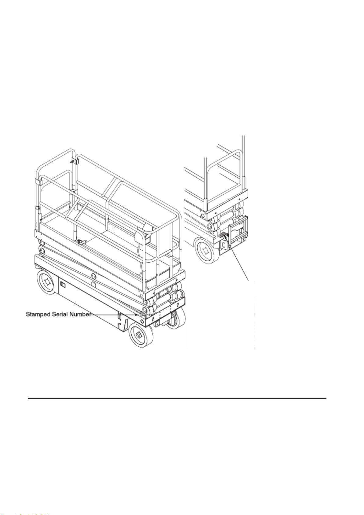
Upright Nameplate is fitted to rear
of Chassis.
Serial Number 51089 - current
English
When contacting Snorkel for service or parts information, be sure to include the MODEL and SERIAL
NUMBER from the equipment Nameplate.
Should the nameplate be missing, the SERIAL NUMBER is also stamped on top of the chassis above
the front axle pivot.
www.Snorkellifts.com
Page 4

Page 5
WARNING
All personnel shall carefully read, understand and follow all safety rules and operating instructions before
operating or performing maintenance on any Snorkel Powered Access work platform.
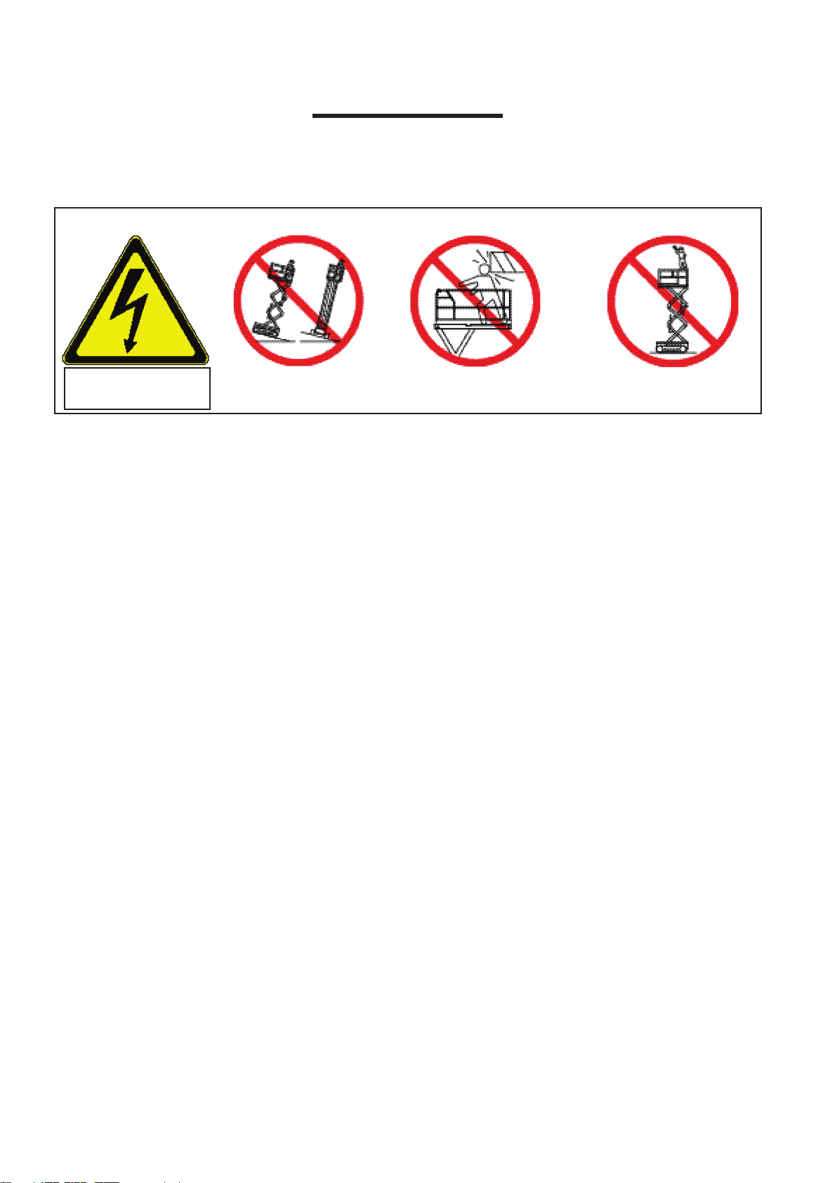
Safety Rules
Electrocution Hazard Tip Over Hazard Collision Hazard
Fall Hazard
THIS MACHINE IS NOT
INSULATED!
USE OF THE AERIAL WORK PLATFORM: This aerial work platform is intended to lift persons and his tools as
well as the material used for the job. It is designed for repair and assembly jobs and assignments at overhead
workplaces (ceilings, cranes, buildings etc) All other uses of the aerial work platform are prohibited!
THIS AERIAL WORK PLATFORM IS NOT INSULATED! For this reason it is imperative to keep a safe distance
from live parts of electrical equipment!
Exceeding the specied permissible maximum load is prohibited! See “Platform Capacity” on page 5 for
details.
The use and operation of the aerial work platform as a lifting tool or a crane is prohibited!
This machine is designed for INDOOR USE ONLY!
DISTRIBUTE all platform loads evenly on the platform.
NEVER operate the machine without rst surveying the work area for surface hazards.
Holes, drop-offs, bumps, curbs, and debris etc. should ALWAYS be AVOIDED!
OPERATE machine only on surfaces capable of supporting wheel loads.
IN CASE OF EMERGENCY push Emergency Stop Switch to deactivate all powered functions.
IF ALARM SOUNDS while platform is elevated, STOP, carefully lower platform. Move machine to a rm, level
surface.
Climbing up the railing of the platform, standing on or stepping from the platform onto buildings, steel or prefab
concrete structures, etc., is prohibited!
Dismantling the entry gate or other railing components is prohibited! Always make certain that the entry gate is
closed and securely locked!
It is prohibited to keep the entry gate in an open position when the platform is raised!
To extend the height or the range by placing of ladders, scaffolds or similar devices on the platform is
prohibited!
NEVER perform service on machine while platform is elevated without blocking elevating assembly.
INSPECT the machine thoroughly for cracked welds, loose or missing hardware, hydraulic leaks, loose wire
connections, and damaged cables or hoses before using.
VERIFY that all labels are in place and legible before using.
NEVER use a machine that is damaged, not functioning properly, or has damaged or missing labels.
To bypass any safety equipment is prohibited and presents a danger for the persons on the aerial work
platform and in its working range.
NEVER charge batteries near sparks or open ame. Charging batteries emit explosive hydrogen gas.
Modications to the aerial work platform are prohibited or permissible only at the approval by Snorkel.
AFTER USE, secure the work platform from unauthorized use by turning the Keyswitch OFF and removing key.
NEVER operate the boom or
drive with the platform elevated
unless on rm, level surface.
NEVER position the machine
without rst checking for overhead
obstructions or other hazards.
NEVER climb, stand or sit
on the platform guardrails or
midrail.
Page 1
Page 6

Page 2
Co n t e n t s p a g e
1. Introduction ........................................................................................................................................... 3
Special Information ..................................................................................................................................3
General Description2. .............................................................................................................................. 4
Special Limitations3. ................................................................................................................................ 5
Platform Capacity ....................................................................................................................................5
Manual Force ...........................................................................................................................................5
Lift Overload Alarm ..................................................................................................................................5
Controls and Indicators4. ......................................................................................................................... 6
Pre-Operation Safety Inspection5. ........................................................................................................... 7
System Function Inspection6. .................................................................................................................. 8
6. Operation .............................................................................................................................................. 9
Platform Extension ...................................................................................................................................9
Travel With the Platform Lowered .............................................................................................................9
Steering ....................................................................................................................................................9
Elevating the Platform ..............................................................................................................................10
Travel with Work Platform Elevated .........................................................................................................10
Lowering the Platform ..............................................................................................................................10
Emergency Lowering ..............................................................................................................................10
Guardrails ................................................................................................................................................11
Lowering Procedure......................................................................................................................11
Raising Procedure ........................................................................................................................11
Parking Brake Release ............................................................................................................................12
Release the Parking Brake ...........................................................................................................12
Engage the Parking Brake ............................................................................................................12
After Use Each Day ..................................................................................................................................12
8. Transporting the Machine ..................................................................................................................... 13
Lifting By Crane........................................................................................................................................13
Moving By Forklift .....................................................................................................................................13
Driving or Winching onto a Truck or Trailer ..............................................................................................14
9. Maintenance ......................................................................................................................................... 15
Blocking The Elevating Assembly ............................................................................................................15
Scissor Brace Installation .............................................................................................................15
Scissor Brace Storage ..................................................................................................................15
Level Sensor ............................................................................................................................................16
Testing the Level Sensor ..............................................................................................................16
Hydraulic Fluid .........................................................................................................................................17
Check Hydraulic Fluid ...................................................................................................................17
Battery Maintenance ...............................................................................................................................17
Battery Charging ......................................................................................................................................17
Daily Inspection and Maintenance Schedule ............................................................................................ 18
Daily Preventative Maintenance Check List ............................................................................................18
Maintenance Table Key ................................................................................................................18
Maintenance Report ......................................................................................................................18
Specications10. ...................................................................................................................................... 19
Labels11. ................................................................................................................................................. 20
Lable Location ..........................................................................................................................................21
Page 7

Page 3
1 INTRODUCTION
1 INTRODUCTION
D A N G E R
! !
W A R N I N G
!
!
C A U T I O N
!
!
This manual covers the X26 Narrow Work Platform.
The manual MUST be stored in the
box provided in the machine cage, AT
ALL TIMES.
Read, understand and follow all safety rules and operating instructions before attempting to operate the
machine.
Figure 1: Manual Storage Information
SPECIAL INFORMATION
Indicates an imminently hazardous situation which, if not avoided, WILL result in
severe injury or death.
Indicates a potentially hazardous situation which, if not avoided, could result in
severe injury or death.
Indicates a potentially hazardous situation which, if not avoided, may result in
minor or moderate injury.
Page 8
Page 4
2 GENERAL DESCRIPTION
D A N G E R
! !
2
3
5
6
7
8
1
9
4
11
10
Rear
Power Module
Control Module
12
2 GENERAL DESCRIPTION
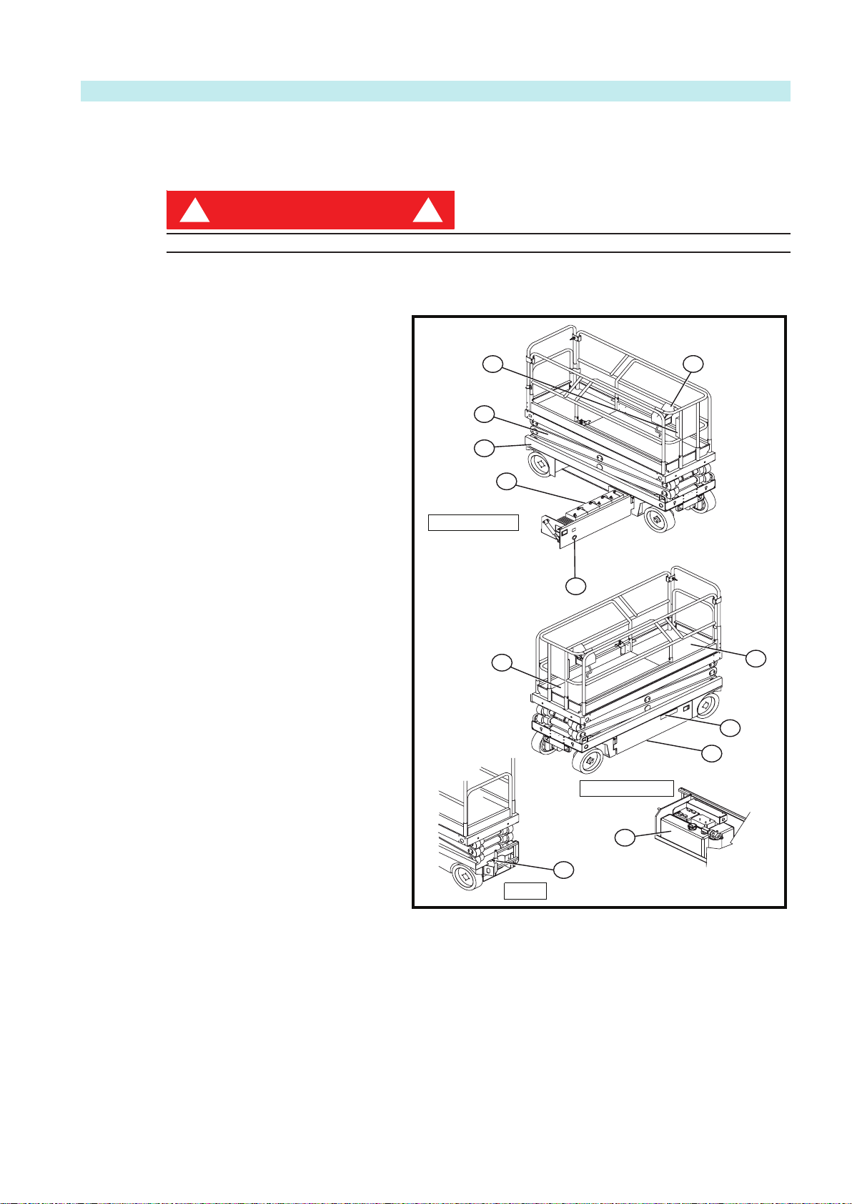
DO NOT use the machine if all guardrails are not properly in place and secured.
Platform Controls1.
Figure 2: X26 Narrow
Manual Case2.
Platform Extension3.
Platform4.
Elevating Assembly5.
Chassis6.
Batteries7.
Charger Outlet Plug8.
Chassis Controls9.
Emergency Lowering Valve Knob10.
Hydraulic Fluid Reservoir11.
Pothole Support Rails (not visible 12.
when machine is Stowed - in
raised Drive position see g 5
page 10
Page 9
Page 5
3 SPECIAL LIMITATIONS
3 SPECIAL LIMITATIONS
D A N G E R
! !
D A N G E R
! !
D A N G E R
! !
D A N G E R
! !
D A N G E R
! !
Travel with the platform raised is limited to creep speed range. Elevating the Work Platform is limited to
rm, level surfaces ONLY.
The elevating function shall ONLY be used when the work platform is level, and on a rm surface. The work
platform is NOT intended to be driven over uneven, rough, or soft terrain.
PLATFORM CAPACITY
The maximum capacity for the MACHINE, including occupants is determined by model and options, and is
listed in «Specications» on page 20.
DO NOT exceed the maximum platform capacity or the platform occupancy limits for this machine.
MANUAL FORCE
Manual force is the force applied by the occupants to objects such as walls or other structures outside the
work platform. The maximum allowable manual force is limited to 200 N (45 lbs.) offeree per preson, with a
maximum of 400 N (90 lbs.) for two or more occupants.
DO NOT exceed the maximum amount of manual force for this machine.
LIFT OVERLOAD ALARM
All models include a feature that alerts the operator when the platform load is exceeded. If the alarm
sounds during the lift function, lower the platform and reduce the platform load.
NEVER operate the machine with a platform load greater than the rated capacity and never in wind
conditions that exceed the maximum allowable for this machine (Beaufort 4). Refer wind chart on page 7
Page 10

Page 6
4 CONTROLS AND INDICATORS
'ULYH6HOHFWRUV
+RUQ%XWWRQ
/LIW/RZHU%XWWRQ
(PHUJHQF\6WRS%XWWRQ
'LVSOD\
-R\VWLFN
4
3
1
2 5
6
Platform Controls
1
2 3 4
4 Controls and Indicators
The operator shall know the location of each control and indicator and have a thorough knowledge of the
function and operation of each before attempting to operate the unit.
Figure 3: Controls and Indicators
Chassis Controls
1. Keyswitch
2. Enable Button
3. Toggle Switch (Up & Down)
4. Emergency Stop Button
Page 11

Page 7
5 PRE-OPERATION SAFETY INSPECTION
5 PRE-OPERATION SAFETY INSPECTION
NOTE: Carefully read, understand and follow all safety rules, operating instructions, labels, and
National Safety Instructions/Requirements. Perform the following steps each day before use.
Open modules and inspect for damage, uid leaks or missing parts.1.
Check the level of the hydraulic uid with the platform fully lowered. See «Hydraulic Fluid» on page 16. 2.
Add recommended hydraulic uid if necessary. See «Specications» on page 21.
Check that uid level in the batteries is correct. See «Battery Maintenance» on page 17.3.
Verify that the batteries are charged.4.
Check that the A.C. extension cord has been disconnected from the charger plug.5.
Check that all guardrails are properly in place and secured.6.
Inspect the machine thoroughly for cracked welds, loose or missing hardware, hydraulic leaks, 7.
damaged cables or hoses, loose wire connections and wheel bolts.
Note X26N operates in Maximum Wind conditions equivalent to Beaufort 4
TABLE OF WIND SPEED/VELOCITY
BEAUFORT CONDITIONS 3 -7
Beaufort
Number
Average Wind
Speed-km/h
Wind Velocity
m/sec
Description Conditions
3 17 4.5 Gentle Breeze Leaves & Twigs in constant
motion, ags wave
4 24 6.7 Moderate
Breeze
Dust & Loose paper raise.
Small Branches begin to
sway.
5 35 9.7 Fresh Breeze Small Trees Sway, Waves
apparent in ponds
6 44 12.5 Strong Breeze Large Branches in motion.
Whistling Heard in overhead
wires. Umbrella use is difcult
7 56 15.5 Near Gale Whole trees in motion. Effort
to walk against the wind.
If in doubt always check wind conditions before machine use.
Note that wind speeds vary considerable at higher levels.
Page 12

6 SYSTEM FUNCTION INSPECTION
W A R N I N G
!
!
6 SYSTEM FUNCTION INSPECTION
NOTE: Refer to Figure 3 for the locations of various controls and indicators.
STAND CLEAR of the work platform while performing the following checks.
Before operating the work platform, survey the work area for surface hazards such as holes, drop-offs,
bumps and debris.
Check in ALL directions, including above the work platform, for obstructions and electrical conductors.
Protect the control console cable from possible damage while performing checks.
1. Move the machine, if necessary, to an unobstructed area to allow for full elevation.
2. Twist and pull the Chassis Emergency Stop button to the ON position.
3. Twist and pull the Platform Emergency Stop button to the ON position.
4. Turn and hold the Chassis Key Switch to the ON position. Push the Chassis Lift/Lower Switch to the
UP position and raise the platform approximately 2,1 m (7 feet).
5. BLOCK THE ELEVATING ASSEMBLY AS DESCRIBED ON page 15.
6. Visually inspect the elevating assembly, lift cylinder, cables, and hoses for cracked welds and structural
damage, loose hardware, hydraulic leaks, loose wire connections, and erratic operation. Check for
missing or loose parts.
7. Verify that the Pothole Support Rails have rotated into position under the machine.
8. REMOVE THE SCISSOR BRACE AS DESCRIBED ON page 15.
9. Push the Chassis Lift/Lower Switch to the UP position and fully elevate the platform.
10. Partially lower the platform by pushing Chassis Lift/Lower Switch to LOWER, and check for proper
operation of the audible lowering alarm.
11. Open the Emergency Lowering Valve (see Figure 5) by pulling the knob out to check for proper
operation. When the platform is lowered, release the knob.
12. Push the Chassis Emergency Stop Switch to check for proper operation. All machine functions should
be disabled. Pull out the Chassis Emergency Stop Switch to resume.
13. Check that the route is clear of obstacles (persons, obstructions, holes, and drop-offs, bumps and
debris), is level, and is capable of supporting the wheel loads.
14. Mount the platform and properly close the entrance.
15. Mount the platform and select DRIVE mode.
Page 8
NOTE: Use both HI and LOW drive (if applicable) when performing the following step.
16. While engaging the Interlock Switch, move the Control Handle to FORWARD, then REVERSE, to
check for speed control.
17. Push the Steering Switch RIGHT, then LEFT, to check for steering control.
18. Select LIFT mode. Grasp the Control Handle, engaging the Interlock Switch, and push it forward to
check platform lift controls. Raise the platform to full elevation.
19. Pull back on the Control Handle. The platform should descend and the audible lowering alarm should
sound.
20. Push the Platform Emergency Stop Switch to check for proper operation. All machine functions should
be disabled. Pull out the Platform Emergency Stop Switch to resume.
Page 13

7 OPERATION
3ODWIRUP([WHQVLRQ
)RRW/HYHUGHFNORFNDVVHPEO\
1
2
Before operating the work platform, ensure that the Pre-Operation Safety Inspection and System Function
Inspection have been completed and that any deciencies have been corrected.
NOTE: Never operate a damaged or malfunctioning machine.
The operator must be thoroughly trained on this machine.
PLATFORM EXTENSION
7 OPERATION
Mount the platform and properly 1.
close and secure the entrance.
Depress the foot lever located at the 2.
rear of the platform extension. Push
the platform extension forward until
the pin engages the front stop.
To retract the platform extension, 3.
depress the foot lever and pull the
platform extension toward the rear of
the machine until the pin engages the
rear stop.
TRAVEL WITH THE
PLATFORM LOWERED
Check that the route is clear of 1.
obstacles (persons, obstructions,
holes, drop-offs, bumps, and debris),
is level, and is capable of supporting
the wheel loads.
Verify that the Chassis Key Switch 2.
is turned to ON and the Chassis
Emergency Stop Switch is ON
(pulled out).
Mount the platform and properly 3.
close the entrance.
Check clearances above, below, and 4.
to the sides of platform.
Pull the Platform Emergency Stop 5.
Switch out to the ON position.
Select DRIVE mode.6.
Figure 4: Platform Extension
1. Platform Extension
2. Foot Lever (deck lock) assembly
NOTE: Choose between standard drive and extra torque depending on the gradient.
7. Engage the Interlock Switch and move the Control Handle to FORWARD or REVERSE to travel in the
desired direction. The speed of the machine will vary depending on how far from centre the Control
Handle is moved.
STEERING
1. Turn the Lift/Drive Switch to DRIVE.
2. While engaging the Interlock Switch, push the Steering Switch to the RIGHT or LEFT to turn the wheels
in the desired direction. Observe the tires while manoeuvring the machine to ensure proper direction.
NOTE: Steering is not self-centering. Wheels must be returned to the straight ahead position by
operating the Steering Switch.
Page 9
Page 14

Page 10
7 OPERATION
W A R N I N G
!
!
Emergency
Lowering Valve
Knob
ELEVATING THE PLATFORM
NOTE: The Pothole Support Rails will deploy automatically as the platform elevates and will remain
deployed when traveling in the Elevated position refer g 5. They will automatically retract when the
platform has been lowered completely and machine is about to be driven refer g 2 & 4.
TRAVEL WITH WORK PLATFORM ELEVATED
NOTE: The machine will travel at reduced speed when the platform is elevated.
Locate a rm, level surface.1.
Select LIFT mode.2.
While engaging the Interlock Switch, push the Control Handle FORWARD.3.
If the machine is not level the level sensor alarm will sound and the machine will not lift or drive.4.
If the level sensor alarm sounds the platform must be lowered and the machine moved to a rm, level 5.
surface before attempting to elevate the platform.
Check that the route is clear of surface hazards such as holes, drop-offs, bumps, curbs, or debris.1.
Check that the route is level, and is capable of supporting the wheel loads.2.
Check clearances above, below, and to the sides of platform.3.
Select DRIVE mode.4.
Engage the Interlock Switch and move the Control Handle to FORWARD or REVERSE to travel in the 5.
desired direction. The speed of the machine will vary depending on how far from centre the Control
Handle is moved.
If the machine is not level the level sensor alarm will sound and the machine will not lift or drive.6.
If the level sensor alarm sounds the platform must be lowered and the machine moved to a rm, level 7.
surface before attempting to elevate the platform.
LOWERING THE PLATFORM
Select LIFT mode.1.
Check around the base of the platform to ensure that 2.
no one is in contact with the machine. Engage the
Interlock Switch and pull back on the Control Handle
to lower the platform.
The platform will stop when it reaches the pre-3.
determined safety cutout height. Inspect around
the machine to ensure no one is in contact with the
machine. After a four-second time delay, lower the
platform as in step 2.
EMERGENCY LOWERING
If the platform should fail to lower, NEVER climb down
the scissor assembly.
A second operative should operate the Emergency
Lowering Valve Knob while keeping clear of the scissor
assembly.
The Emergency Lowering Valve Knob is located at the
rear of the machine, behind the ladder.
Open the Emergency Lowering Valve by pulling and 1.
holding the knob.
To close, release the knob. The platform will not 2.
elevate if the Emergency Lowering Valve is open.
Fig 5:Travel With Scissors Elevated
Pothole Protection Rails Lowered
Figure 5: Emergency Lowering Knob
Emergency
Lowering
Valve Knob
Page 15

Page 11
7 OPERATION
GUARDRAILS
W A R N I N G
!
!
C A U T I O N
!
!
1
2
3
4
5
4
1. Platform Extension
2. Platform Controls
3. Platform Extension Retaining Pins
4. Side-rail Retaining Pins
5. Rear Top-rail Retaining Pins
Retaining Pin Detail
Engaged
Retracted
The guardrails may be lowered for the purpose of
passing through a standard doorway.
Guardrails must be returned to proper position
before using the machine.s
DO NOT use the machine if all guardrails are not
properly in place and secured.
LOWERING PROCEDURE
Ensure that the platform extension is fully 1.
retracted and the deck lock pin is engaged (see
«Platform Extension» on page 9).
Place the Platform Controls on the deck of the 2.
platform extension.
Lower the platform extension guardrail;3.
a. Pull to retract the retaining pins.
b. As the retaining pin is pulled, the rail will
drop slightly and hold the pin in the retracted
position.
c. Hold the mid-rail with one hand as you retract
the nal retaining pin.
Retaining Pin Detail
1. Platform Extension
2. Platform Controls
3. Platform Extension Retaining Pins
4. Side-rail Retaining Pins
5. Rear Top-rail Retaining Pins
Figure 6: Guardrails
Engaged Retracted
The guardrail could drop suddenly when the nal retaining pin is retracted. Keep hands away from the slide tubes to
prevent injury.
d. Push down on the platform extension guardrail to lower it completely.
e. The retaining pins will remain in the retracted position.
4. Lower the side guardrails and rear guardrail as a single unit;
• Repeat steps 3a through 3c.
5. Lower the rear top-rail;
• Pull the two retaining pins and lower the rear top-rail completely.
RAISING PROCEDURE
1. Raise the side guardrails and rear guardrail as one unit;
• Pull up on the side guardrails and raise them until all the retaining pins engage.
2. Raise the rear top-rail;
• Pull up on the rear top-rail until the retaining pins engage.
3. Raise the platform extension guardrail;
4. Hang the controller on the platform extension guardrail.
• Pull up on the platform extension guardrail and raise it until all the retaining pins engage.
Page 16

7 OPERATION
W A R N I N G
!
!
C A U T I O N
!
!
e
replaced before the braking function is re-instated.
3. G1/8 Plugs
2
3
3
4
1
1
1. Motor Mount
2. Drive Motor
3. Brake Release Nut
4. Wheel
FRONT
PARKING BRAKE RELEASE
NEVER winch or move the machine faster than 0,3 m/sec. (1 ft./sec).
NEVER operate the machine with the parking brakes released. Serious injury or damage could result.
DO NOT release the parking brakes if the machine is on a slope.
RELEASE THE PARKING
BRAKE
Perform the following only when the machine will not operate under its own power and it is necessary to move
the machine or when winching onto a transport vehicle (see «Transporting the Machine»).
The parking brakes are integral to the drive motors. Each drive motor has two brake release screws. Release
and engage the parking brakes one wheel at a time. Turn the brake release screws in stages (½ turn at a
time) to prevent possible binding of the brake mechanism.
Figure 7: Parking Brake Release
FRONT
The front wheel motors each have two
brake release nuts.
IMPORTANT: Turn the nuts alternately
in ½ turn increments to insure uniform
adjustment and prevent binding.
1. Chock the rear wheels to prevent the
machine from rolling.
2. Using a 5mm Allen Key, remove the
two G1/8 plugs from the motor body
turning counter-clockwise.
3. Using a 5mm Allen Key turn the
inner G1/8 plug as far as possible in a
clockwise direction.
4. The brake is released.
To avoid confusion, the outer plugs should not be replaced before the braking function is re-instated.
1. Motor Mount
2. Drive Motor
3. Brake Release Nut
4. Wheel
ENGAGE THE PARKING BRAKE
1. Chock the rear wheels to prevent the machine from rolling.
2. Using a 5mm Allen Key turn the inner G1/8 plug as far as possible in the counter-clockwise direction.
3. Fit the two outer G1/8 plugs then, using the 5mm Allen Key, screw in clockwise until tight.
AFTER USE EACH DAY
1. Ensure that the platform is fully lowered.
2. Park the machine on a rm, level surface, preferably under cover, secure against vandals, children and
unauthorized operation.
3. Turn the Chassis Key Switch to OFF and remove the key to prevent unauthorized operation.
Page 12
Page 17

8 TRANSPORTING THE MACHINE
D A N G E R
! !
Front
Rear
REAR
FRONT
Rear Tie
Down/Lift Point
Front Tie Down/Lift
Point
Forklift Here
Forklift Pockets
Rear Tie
Down/Lift Point
Always use a transport vehicle when moving a machine to a work site. Towing the machine over long
distances will damage the machine and void the warranty.
LIFTING BY CRANE
See specications for the weight of the machine
and be certain that the crane is of adequate
capacity to lift the machine.
Secure straps to chassis tie down/lifting points
only (see Figure 8).
MOVING BY FORKLIFT
Fork-lifting is for transport only.
See specications for the weight of the machine
and be certain that the forklift is of adequate
capacity to lift the machine.
8 TRANSPORTING THE MACHINE
Figure 8: Secure Crane Straps
Forklift from the rear of the machine using
the forklift pockets provided. If necessary, the
machine may be forklifted from the side by lifting
under the Chassis Modules, (see Figure 9).
FRONT
Front Rear
Figure 9: Tie Down and Lift Points
Rear Tie
Down/Lift
Point
Rear Tie
Down/Lift Point
Forklift Pockets
Front Tie Down/Lift
Point
Forklift Here
REAR
Page 13
Page 18

8 TRANSPORTING THE MACHINE
W A R N I N G
!
!
C A U T I O N
!
!
DRIVING OR WINCHING ONTO A TRUCK OR TRAILER
Never winch faster than 0,3 m/sec. (1 ft./sec).
Never operate the machine with the parking brakes released. Serious injury or damage could result.
1. Loading the machine onto the truck or trailer;
A. To Drive the machine onto the transport vehicle:
• Turn the Lift/Drive Switch to DRIVE LOW(hi-torque mode) and drive the machine up the ramp and
into transport position.
• Set the wheels straight and turn off the machine.
• Chock the wheels.
B. To Winch the machine onto the transport vehicle:
• Drive the machine up to the ramp.
• Attach the winch cable to the tie down/lifting points.
• Release the parking brakes (refer to «Parking Brake Release» on page 12).
• Winch the machine into transport position
• Chock the wheels.
• Re-engage the parking brakes.
2. Secure the machine to the transport vehicle with chains or straps of adequate load capacity attached to
the chassis tie down/lifting points (refer to Figure 13).
Overtightening chains or straps attached to the Tie Down points may result in damage to the machine.
Page 14
Page 19

9 MAINTENANCE
W A R N I N G
!
!
Rotate Brace
Clockwise to
Block
Counterclockwise
to Store
Brace Rests
on Weldment
when in
Blocking
Position
Never perform service while the platform is elevated without rst blocking the elevating assembly. DO NOT
stand in the elevating assembly area while deploying or storing the brace.
BLOCKING THE ELEVATING ASSEMBLY
9 MAINTENANCE
SCISSOR BRACE
INSTALLATION
Park the machine on a rm, level 1.
surface.
Pull Chassis Emergency Stop Switch to 2.
the ON position.
Pull Platform Emergency Stop Switch to 3.
the ON position.
Turn and hold the Chassis Key Switch 4.
to CHASSIS.
Push the Chassis Lift/Lower Switch to 5.
LIFT to elevate the platform until the
scissor brace can be rotated to the
vertical position.
From the rear of the machine, lift the 6.
scissor brace from its stowed position.
Rotate upward and outward, then down
until it is hanging vertically below its
attachment point.
Lower the platform by pushing the 7.
Chassis Lift/Lower Switch to LOWER
and gradually lower the platform until
the scissor brace is supporting the
platform.
SCISSOR BRACE STORAGE
Using the Chassis Controls, gradually 1.
elevate the platform until the scissor
brace is clear.
Rotate the scissor brace outward and 2.
upward over its mounting point until it
rests in the stowed position.
Lower the platform by pushing the 3.
Chassis Lift/Lower Switch to LOWER to
completely lower the platform.
Figure 10: Scissor Brace
Rotate Brace
Clockwise to Block
Counterclockwise to
Store
Brace Rests
on Weldment
when in Blocking
Position
Page 15
Page 20

Page 16
9 MAINTENANCE
W A R N I N G
!
!
LEVEL SENSOR
Never perform service while the platform is elevated without rst blocking the elevating assembly. DO NOT
stand in the elevating assembly area while deploying or storing the brace.
The Level Sensor Is located on the chassis between the scissor sections and is covered with a protective
metal box.
Figure 10: Level Sensor
The Level Sensor is located on the chassis of
the machine
These units are sealed and pre-set and require
no recalibration or adjustment.
HYDRAULIC FLUID
The hydraulic uid reservoir is located in the control module door.
NOTE: Never add uid if the platform is elevated.
CHECK HYDRAULIC FLUID
Make sure that the platform is fully 1.
lowered.
Open the chassis door.2.
Remove the ller cap from the hydraulic 3.
uid reservoir.
Check the uid level on the dipstick on the 4.
ller cap.
Add the appropriate uid to bring the level 5.
to the FULL mark. See «Specications» on
page 21.
Figure 12: Hydraulic Fluid Reservoir and Dipstick
Page 21

Page 17
9 MAINTENANCE
W A R N I N G
!
!
W A R N I N G
!
!
%DWWHU\&KDUJHU
&KDUJH,QGLFDWRU
&KDUJHU3OXJ
%DWWHULHV
4
1
2
3
BATTERY MAINTENANCE
Hazard of explosive gas mixture. Keep sparks, ame, and smoking material away from batteries.
Always wear safety glasses when working near batteries.
Battery uid is highly corrosive. Thoroughly rinse away any spilled uid with clean water.
Always replace batteries with Snorkel batteries or manufacturer approved replacements weighing 30 kg (66
lbs.) each.
• Check the battery uid level daily, especially if the machine is being used in a warm, dry climate.
• If electrolyte level is lower than 10 mm (3/8in.) above the plates add distilled water only. DO NOT use
tap water with high mineral content, as it will shorten battery life.
• Inspect the battery regularly for signs of cracks in the case, electrolyte leakage and corrosion of the
terminals.
• Inspect cables regularly for worn spots or breaks in the insulation and for broken cable terminals.
• Keep the terminals and tops of the batteries clean.
• Refer to the Service Manual to extend battery life and for
complete service instructions.
Figure 13: Battery Charger
BATTERY CHARGING
Charge the batteries at the end of each work shift or sooner if the
batteries have been discharged.
Charge the batteries in a well ventilated area.
Do not charge the batteries when the machine is near a source of
sparks or ames.
Permanent damage to the batteries will result if the batteries are not
immediately recharged after discharging.
Never leave the battery charger operating for more than two days.
Never disconnect the cables from the batteries when the charger is
operating.
Keep the charger dry.
Check the battery uid level. If the battery uid level is lower 1.
than 10 mm (3/8 in.) above the plates add distilled water only.
Connect an appropriate extension cord to the charger outlet plug 2.
in the left module door. Plug the extension cord into a properly
grounded outlet of proper voltage and frequency.
The charger turns on automatically after a short delay. The 3.
LED charge indicator will illuminate. After completion of the
charge cycle the LED will blink, indicating that the charger is in
a continuing maintenance mode. DO NOT leave the charger
plugged in for more than 48 hours, as permanent damage to the
batteries may occur.
NOTE: The battery charger circuit must be used with a GFI (Ground Fault Interrupt) outlet.
NOTE: DO NOT operate the machine while the charger is plugged in.
1. Battery Charger
2. Charge Indicator
3. Charger Plug
4. Batteries
Page 22

DAILY INSPECTION AND MAINTENANCE SCHEDULE
W A R N I N G
!
!
DAILY INSPECTION AND MAINTENANCE SCHEDULE
The Complete Inspection consists of periodic visual and operational checks, along with periodic minor
adjustments that assure proper performance. Daily inspection will prevent abnormal wear and prolong the
life of all systems. Perform the inspection and maintenance items daily. Inspection and maintenance shall
be performed by personnel who are trained and familiar with mechanical and electrical procedures.
Before performing preventative maintenance, familiarize yourself with the operation of the machine.
Always block the elevating assembly whenever it is necessary to perform maintenance while the platform is
elevated.
DAILY PREVENTATIVE MAINTENANCE CHECK LIST
The daily preventative maintenance checklist has been designed for machine service and maintenance.
Please photocopy the Daily Preventative Maintenance Checklist and use the checklist when inspecting the
machine.
MAINTENANCE TABLE KEY MAINTENANCE REPORT
Y = Yes/Acceptable Date:
N = No/Not Acceptable Owner:
R = Repaired/Acceptable Model No:
Serial No:
Serviced By: _________________________________
COMPONENT INSPECTION OR SERVICES Y N R
Battery Check electrolyte level.
Check battery cable condition.
Chassis Check hoses for pinch or rubbing points.
Check welds for cracks.
Control Cable Check the exterior of the cable for pinching, binding or wear.
Controller Check switch operation.
Drive Motors Check for operation and leaks.
Elevating Assembly Inspect for structural cracks.
Emergency Lowering System Operate the emergency lowering valve and check for serviceability.
Entire Unit Check for and repair collision damage.
Hydraulic Fluid Check uid level.
Hydraulic Pump Check for hose tting leaks.
Hydraulic System Check for leaks.
Labels Check for peeling, missing, or unreadable labels & replace.
Platform Deck and Rails Check welds for cracks.
Platform Deck and Rails Check condition of deck.
Tyres and Wheels Check for damage.
Page 18
Page 23

10 SPECIFICATIONS
11 SPECIFICATIONS
ITEM
Platform Size
Platform Extension In 0,71 m x 2,21 m [28 in. x 87 in.]
Platform Extension Out 0,71 m x 3,20 m [28 in. x 126 in.]
Max. Platform Capacity
Standard 340 kg [750 lbs.]
on Extension 110 kg [250 lbs.]
Max. No. of occupants
Standard (total) 3 People Indoors /1 Person Outdoors (Max Wnd Speed 7m/s)
on Extension 1 person
Maximum Wheel Load 818 kg [1,800 lbs.]
Maximum Chassis Inclination 2.0» side/side - 2.0» front/rear
Height
Working Height 9,93 m [32.5 ft.]
Max. Platform Height 7,93 m [26 ft.]
Min. Platform Height 1,09 m [43 in.]
Dimensions
Weight 2358 kg [5200 lbs.]
Overal Wdth 0,82 m [32.5 in.]
Overal Height 2,19 m [86 in.]
Overal Height, Rails Lowered 1,99 m [78.25 in.]
Overal Length, Extension In 2,35 m [92.5 in.]
Overal Length, Extension Out 3,26 m [128.5 in.]
Drivable Height 7,93 m [26 ft.]
Drive Speed
Platform Lowered 0 to 3,2 km/h [0 to 2.0 mph]
Platform Raised 0 to 0,8 km/h [0 to 0.50 mph]
Energy Source 24 Volt Battery Pack (4, 6 Volt 235Ah Batteries, min. wt. 30 kg [66 lbs.] each)
Motor 24 Volt 4 Horse Power DC Electric Motor
System Voltage 24 Volt DC
Battery Charger 25 A, 110/220 VAC
Hydraulic Reservoir Capacity 15 L [4 US Gallons]
Maximum Hydraulic Pressure 207 bar [3000 psi]
Hydraulic Fluid
Normal Temperature (0° C [>32° F]) ISO #32
Low Temperature (0° C [<32° F]) ISO #32
Extreme Temperature (-17° C [<0° F]) ISO #15
Lift System One Single Stage Lift Cylinder
Lift Speed Lift, 42 sec/Lower 40 sec.
Control System Proportional Control Handle with Interlock Switch, Rotary Lift/Drive Switch,
urive system Dual Front Wheel Hydraulic Motors
Tyres 381 mm [15 in.] Diameter Solid Rubber, non-marking
Parking Brake Dual Spring Applied, Hydraulic Release
Turning Radius 203 mm [8 in.] Inside
Maximum Gradeability 14° [25%]
Wheel Base 1,9 m [74.75 in.]
Guardrails 1,1 m [43.25 in.] High
Toe Boards 152 mm [6 in.]
Ground Clearance 89 mm [3.5 in.]
X26N
and Red Mushroom Emergency Stop Switch
Sound Power Level 69dBA.
Max Wind speed for this machine is Beaufort wind force 4(refer page 7)
Specications are subject to change without notice. Hot weather or heavy use may affect
performance. Refer to the Service Manual for complete parts and service information.
Meets or exceeds all applicable CE and machinery directive requirements MD98/37/EC.
Page 19
Page 24

Page 20
ILLUSTRATED PARTS LIST
BATTERY
MAINTAIN BATTERY FLUID
AT RECOMENDED LEVEL
005221-000
HYDRAULIC FLUID
HYDRULIKOEL
HUILE HYDRAULIQUE
FLUIDO HIDRAULICO
060197-001
9
100102-900
066561-900
067195-001
068635-001 x2
12
19
503724-000 x2
067195-001
15
101210-000
101210-000
11
2
3
21
20
18
10
13
066561-900
1
4
7
8
5
6
14
16
17
508661-000 x2
X26N
508669-000 x2
010076-901
100076-901
- +
26.3 kg+
062562-951 x4
066556-900 x2
066522-900
066522-900
066551-950
066551-950
MAX = 113 kg =
+1
100102-900
THIS PLATFORM IS
NOT INSULATED.
DIESE ARBEITSBÜHNE
IST NICHT ISOLIERT.
CETTE PLATEFORME
N'EST PAS ISOLEE.
501453-000
501453-000 x4
502480-000
014222-903
014222-903 x4
503721-000
CUTOUT CUTOUT
CUTOUT
CUTOUT
503723-000
503723-000
504199-007
MAX = 340 kg MAX = 340 kg
+
1
+
3
504199-007
7 m/s
Page 25

Page 21
ILLUSTRATED PARTS LIST
1
2
4
18
18
14
18
13
6
12
12
20
17
19
18
8
30
7
10
18
4
11
16
5
Front
Panel
Control Module
Upper Control Box
Battery Module
Access/Rear
View
11
11
15
Page 26

Page 27

Page 28

Local Distributor / Lokaler Vertiebshändler / Distributeur local
El Distribuidor local / ll Distributore locale
EURO PE , MIDDL E EA S T
AFRI CA & A SI A
PHONE: +44 (0) 845 1550 057
FAX: +44 (0) 845 1557 756
NORT H & SO UTH AME RI CA
PHONE: +1 785 989 30 00
TOLL FRE E: +1 800 225 0317
FAX: +1 785 989 3070
AUSTRALIA
PHONE: +61 2 9725 40 00
FAX: +61 2 9609 3057
NEW ZE AL AN D
PHONE: +64 6 3689 168
FAX: +64 6 3689 164
 Loading...