

X26-32
Operator Manual
This first section of the Operator manual is the English language version.
Betriebsanleitung
Im zweiten Abschnitt dieser Betriebsanleitung finden Sie die Deutsche Version.
Manuel Utilisateur
èLa troisième section de ce manuel est la version en langue Française.
Manual del Usuario
El apartado cuarto de este manual del usuario corresponde a la versión en Español.
Manuale d’Uso
La quinta sezione di questo manuale d'uso è la versione in lingua Italiana.
(EN) Manual part number 504165-002.
(DE) Bestellnummer 504165-002.
WARNING
The X32 Machine has been re-assessed to ensure
compliance to the Machinery Directive (2006/42/EC).
The Machine rating has been changed from:
Windspeed rating of 12.5 m/s (Beaufort 6)
To
Windspeed rating of 7 m/s (Beaufort 4)
Please attach to the front cover of
your X32 manual
510329-000
(FR) Manuel Pièce numéro 504165-002.
(ES) El número de referencia para el manual es el 504165-002.
(IT) Manuale Ricambi Numero 504165-002.

X 26-32
X26 Serial Numbers 50906 – 53099
X32 Serial Numbers 50322 – 53099
ENGLISH
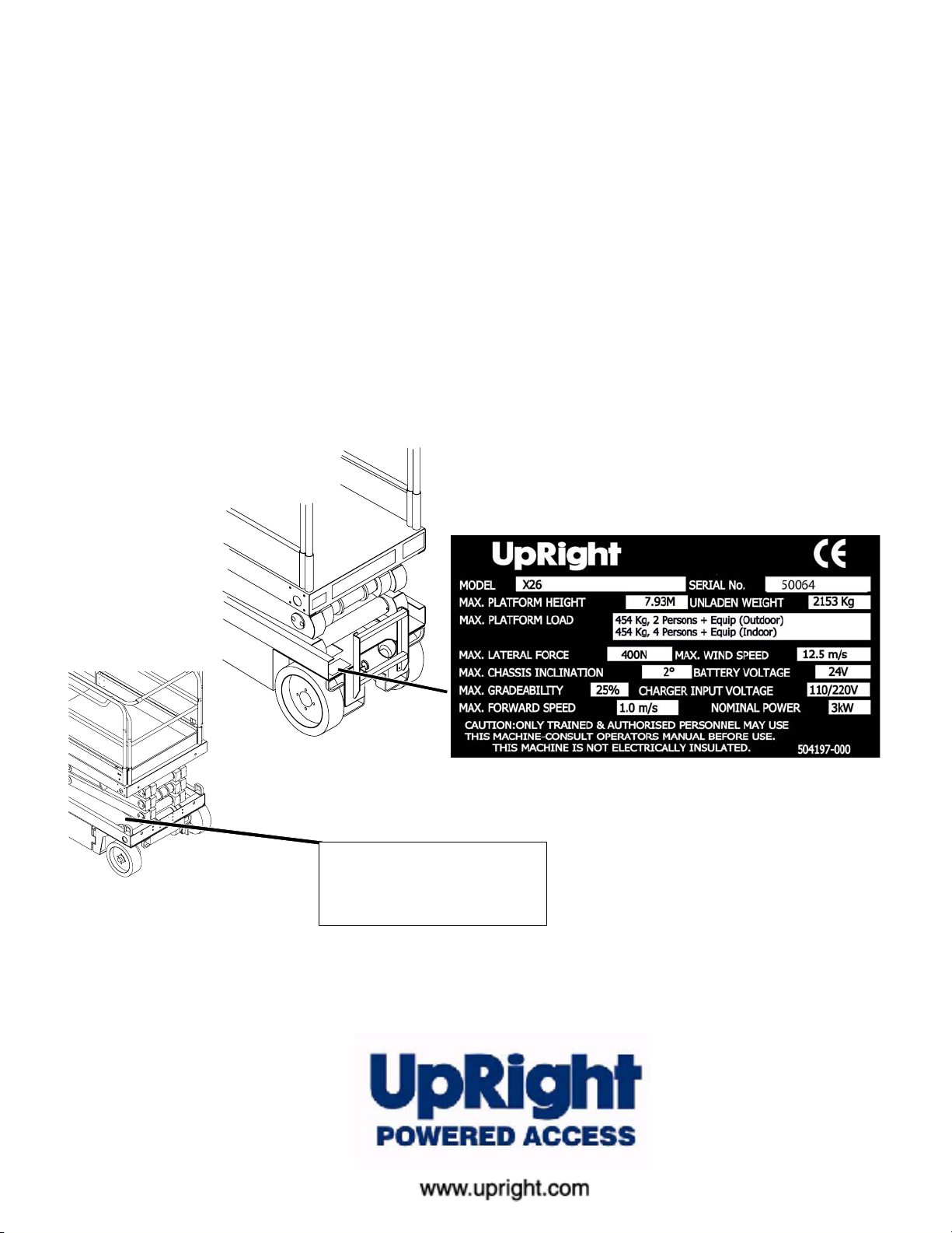
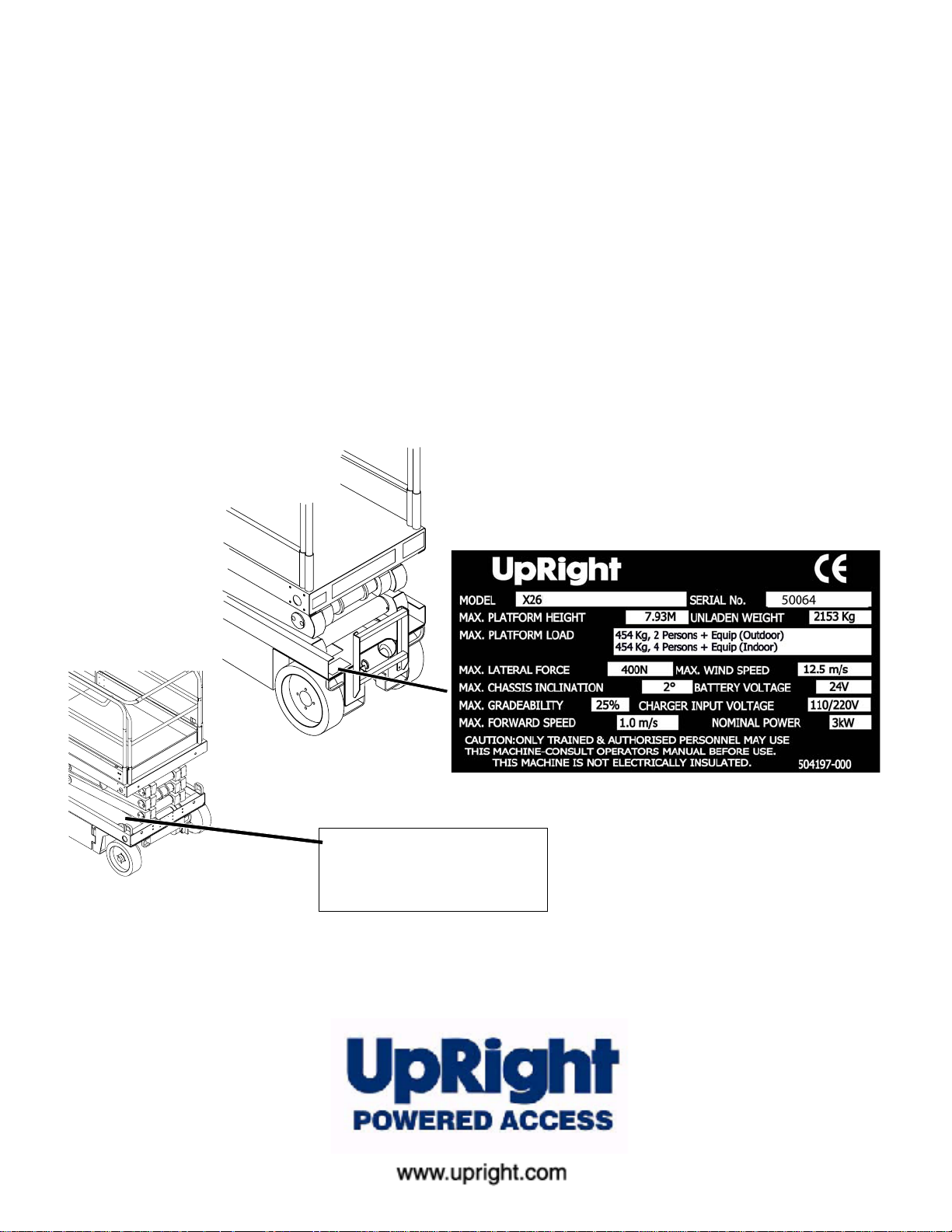
When contacting Upright for service or parts information, be sure to include the MODEL and SERIAL NUMBERS from the
equipment nameplate. Should the nameplate be missing, the SERIAL NUMBER is also stamped on top of the chassis
above the front axle pivot.
Stamped Serial Number
Estampille de numéro de série
Eingestanzte Seriennummer

OPERATION MANUAL
WARNING
All personnel shall carefully read, understand and follow all safety rules and operating
instructions before operating or performing maintenance on any UpRight aerial w ork platform.
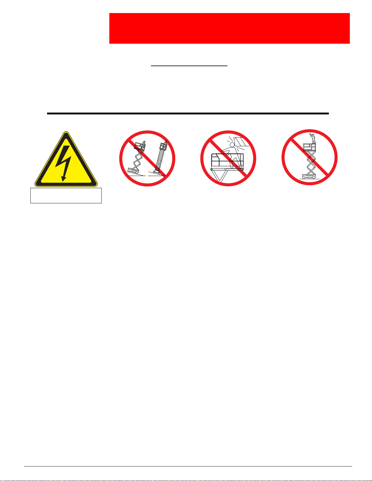
Safety Rules
Electrocution Hazard Tip Over Hazard Collision Hazard
THIS MACHINE IS NOT
INSULATED!
USE OF THE AERIAL WORK PLATFORM: This aerial work platform is intended to lift persons and his tools as well as the material
used for the job. It is designed for repair and assemb ly jobs and assignments at overhead workplaces (ceilings, cranes, roof structures,
buildings etc.). All other uses of the aerial work platform are prohibited!
THIS AERIAL WORK PLATFORM IS NOT INSULATED! For this reason it is imperative to keep a safe distance from live parts of electrical equipment!
Exceeding the specified permissible maximum load is prohibited! See “Special Limitations” on page 4 for details.
The use and operation of the aerial work platform as a lifting tool or a crane (lifting of loads from below upwards or from up high on
down) is prohibited!
NEVER exceed the manual force allowed for this machine. See “Special Limitations” on page 4 for details.
DISTRIBUTE all platform loads evenly on the platform.
NEVER operate the machine without first surveying the work area for surface hazards such as holes, drop-offs, bumps, curbs, or debris;
and avoiding them.
OPERATE machine only on surfaces capable of supporting wheel loads.
NEVER operate the machine when wind speeds exceed this machine’s wind rating. See “Beaufort Scale” on page 4 for details.
IN CASE OF EMERGENCY push EMERGENCY STOP switch to deactivate all powered functions.
IF ALARM SOUNDS while platform is elevated, STOP, carefully lower platform. Move machine to a firm, level surface.
Climbing up the railing of the platform, standing on or stepping from the platform onto buildings, steel or prefab concrete structures, etc.,
is prohibited!
Dismantling the swing gate or other railing components is prohibited! Always make certain that the swing gate is closed and securely
locked!
It is prohibited to keep the swing gate in an open position (held open with tie-straps) when the platform is raised!
To extend the height or the range by placing of ladders, scaffolds or similar devices on the platform is prohibited!
NEVER perform service on machine while platform is elevated without blocking elevating assembly.
INSPECT the machine thoroughly for cracked welds, loose or missing hardware, hydraulic leaks, loose wire connections, and damaged
cables or hoses before using.
VERIFY that all labels are in place and legible before using.
NEVER use a machine that is damaged, not functioning properly, or has damaged or missing labels.
To bypass an y safety equipment is prohibited and presents a danger for the persons on the aerial work platform and in its working
range.
NEVER charge batteries near sparks or open flame. Charging batteries emit explosive hydrogen gas.
Modifications to the aerial work platform are prohibited or permissible only at the approval by UpRight.
AFTER USE, secure the work platform from unauthorized use by turning both keyswitches off and removing key.
The driving of MEWPs on the public highways is subject to regulations made under the Road Traffic Acts.
NEVER elevate the platform or drive
the machine while elevated unless the
machine is on a firm, level surface.
NEVER position the platform
without first checking for overhead
obstructions or other hazards.
Fall Hazard
NEVER climb, stand, or sit on
platform guardrails or midrail.
Page 1

504165-002
C
ONTENTS
Introduction. . . . . . . . . . . . . . . . . . . . . . . . . . . . . . . . . . . . . . . . . . . . . . . . . . . . . . . . . . . . . . . . . . . . . . . . . .3
General Description . . . . . . . . . . . . . . . . . . . . . . . . . . . . . . . . . . . . . . . . . . . . . . . . . . . . . . . . . . . . . . . . . . .3
Special Limitations. . . . . . . . . . . . . . . . . . . . . . . . . . . . . . . . . . . . . . . . . . . . . . . . . . . . . . . . . . . . . . . . . . . .4
Platform Capacity . . . . . . . . . . . . . . . . . . . . . . . . . . . . . . . . . . . . . . . . . . . . . . . . . . . . . . . . . . . . . . . . . . . . . . . . . . . 4
Manual Force . . . . . . . . . . . . . . . . . . . . . . . . . . . . . . . . . . . . . . . . . . . . . . . . . . . . . . . . . . . . . . . . . . . . . . . . . . . . . . 4
Beaufort Scale. . . . . . . . . . . . . . . . . . . . . . . . . . . . . . . . . . . . . . . . . . . . . . . . . . . . . . . . . . . . . . . . . . . . . . . . . . . . . . 4
Lift Overload Alarm . . . . . . . . . . . . . . . . . . . . . . . . . . . . . . . . . . . . . . . . . . . . . . . . . . . . . . . . . . . . . . . . . . . . . . . . . . 4
Controls and Indicators . . . . . . . . . . . . . . . . . . . . . . . . . . . . . . . . . . . . . . . . . . . . . . . . . . . . . . . . . . . . . . . .5
Pre-Operation Safety Inspection . . . . . . . . . . . . . . . . . . . . . . . . . . . . . . . . . . . . . . . . . . . . . . . . . . . . . . . . .6
System Function Inspection . . . . . . . . . . . . . . . . . . . . . . . . . . . . . . . . . . . . . . . . . . . . . . . . . . . . . . . . . . . .7
Operation. . . . . . . . . . . . . . . . . . . . . . . . . . . . . . . . . . . . . . . . . . . . . . . . . . . . . . . . . . . . . . . . . . . . . . . . . . . .8
Platform Extension . . . . . . . . . . . . . . . . . . . . . . . . . . . . . . . . . . . . . . . . . . . . . . . . . . . . . . . . . . . . . . . . . . . . . . . . . . 8
Travel With the Platform Lowered. . . . . . . . . . . . . . . . . . . . . . . . . . . . . . . . . . . . . . . . . . . . . . . . . . . . . . . . . . . . . . . 8
Steering. . . . . . . . . . . . . . . . . . . . . . . . . . . . . . . . . . . . . . . . . . . . . . . . . . . . . . . . . . . . . . . . . . . . . . . . . . . . . . . . . . . 8
Elevating the Platform. . . . . . . . . . . . . . . . . . . . . . . . . . . . . . . . . . . . . . . . . . . . . . . . . . . . . . . . . . . . . . . . . . . . . . . . 8
Travel With the Platform Elevated. . . . . . . . . . . . . . . . . . . . . . . . . . . . . . . . . . . . . . . . . . . . . . . . . . . . . . . . . . . . . . . 9
Lowering the Platform . . . . . . . . . . . . . . . . . . . . . . . . . . . . . . . . . . . . . . . . . . . . . . . . . . . . . . . . . . . . . . . . . . . . . . . . 9
Emergency Lowering. . . . . . . . . . . . . . . . . . . . . . . . . . . . . . . . . . . . . . . . . . . . . . . . . . . . . . . . . . . . . . . . . . . . . . . . . 9
X26. . . . . . . . . . . . . . . . . . . . . . . . . . . . . . . . . . . . . . . . . . . . . . . . . . . . . . . . . . . . . . . . . . . . . . . . . . . . . . . . . . . 9
X32. . . . . . . . . . . . . . . . . . . . . . . . . . . . . . . . . . . . . . . . . . . . . . . . . . . . . . . . . . . . . . . . . . . . . . . . . . . . . . . . . . . 9
Lower the Guardrails, X26. . . . . . . . . . . . . . . . . . . . . . . . . . . . . . . . . . . . . . . . . . . . . . . . . . . . . . . . . . . . . . . . . . . . 10
Lowering Procedure. . . . . . . . . . . . . . . . . . . . . . . . . . . . . . . . . . . . . . . . . . . . . . . . . . . . . . . . . . . . . . . . . . . . . 10
Raising Procedure . . . . . . . . . . . . . . . . . . . . . . . . . . . . . . . . . . . . . . . . . . . . . . . . . . . . . . . . . . . . . . . . . . . . . . 10
Fold Down guardrails, X32 . . . . . . . . . . . . . . . . . . . . . . . . . . . . . . . . . . . . . . . . . . . . . . . . . . . . . . . . . . . . . . . . . . . 11
Fold Down Procedure . . . . . . . . . . . . . . . . . . . . . . . . . . . . . . . . . . . . . . . . . . . . . . . . . . . . . . . . . . . . . . . . . . . 11
Erection Procedure . . . . . . . . . . . . . . . . . . . . . . . . . . . . . . . . . . . . . . . . . . . . . . . . . . . . . . . . . . . . . . . . . . . . . 11
Towing or Winching . . . . . . . . . . . . . . . . . . . . . . . . . . . . . . . . . . . . . . . . . . . . . . . . . . . . . . . . . . . . . . . . . .12
Parking Brake Release . . . . . . . . . . . . . . . . . . . . . . . . . . . . . . . . . . . . . . . . . . . . . . . . . . . . . . . . . . . . . . . . . . . . . . 12
After Use Each Day. . . . . . . . . . . . . . . . . . . . . . . . . . . . . . . . . . . . . . . . . . . . . . . . . . . . . . . . . . . . . . . . . . . . . . . . . 12
Hour Meter . . . . . . . . . . . . . . . . . . . . . . . . . . . . . . . . . . . . . . . . . . . . . . . . . . . . . . . . . . . . . . . . . . . . . . . . . . . . . . . 12
Transporting the Work Platform . . . . . . . . . . . . . . . . . . . . . . . . . . . . . . . . . . . . . . . . . . . . . . . . . . . . . . . .13
Preparation for Shipment . . . . . . . . . . . . . . . . . . . . . . . . . . . . . . . . . . . . . . . . . . . . . . . . . . . . . . . . . . . . . . . . . . . . 13
Lifting By Crane. . . . . . . . . . . . . . . . . . . . . . . . . . . . . . . . . . . . . . . . . . . . . . . . . . . . . . . . . . . . . . . . . . . . . . . . . . . . 13
By Forklift . . . . . . . . . . . . . . . . . . . . . . . . . . . . . . . . . . . . . . . . . . . . . . . . . . . . . . . . . . . . . . . . . . . . . . . . . . . . . . . . 13
Driving or Winching onto a Truck or Trailer. . . . . . . . . . . . . . . . . . . . . . . . . . . . . . . . . . . . . . . . . . . . . . . . . . . . . . . 13
Maintenance . . . . . . . . . . . . . . . . . . . . . . . . . . . . . . . . . . . . . . . . . . . . . . . . . . . . . . . . . . . . . . . . . . . . . . . .14
Blocking The Elevating Assembly. . . . . . . . . . . . . . . . . . . . . . . . . . . . . . . . . . . . . . . . . . . . . . . . . . . . . . . . . . . . . . 14
Scissor Brace Installation . . . . . . . . . . . . . . . . . . . . . . . . . . . . . . . . . . . . . . . . . . . . . . . . . . . . . . . . . . . . . . . . . 14
Scissor Brace Stowage . . . . . . . . . . . . . . . . . . . . . . . . . . . . . . . . . . . . . . . . . . . . . . . . . . . . . . . . . . . . . . . . . . 14
Battery Maintenance . . . . . . . . . . . . . . . . . . . . . . . . . . . . . . . . . . . . . . . . . . . . . . . . . . . . . . . . . . . . . . . . . . . . . . . . 15
Battery Charging . . . . . . . . . . . . . . . . . . . . . . . . . . . . . . . . . . . . . . . . . . . . . . . . . . . . . . . . . . . . . . . . . . . . . . . 15
Inspection and Maintenance Schedule. . . . . . . . . . . . . . . . . . . . . . . . . . . . . . . . . . . . . . . . . . . . . . . . . . .16
Daily Preventative Maintenance Checklist. . . . . . . . . . . . . . . . . . . . . . . . . . . . . . . . . . . . . . . . . . . . . . . .16
Labels . . . . . . . . . . . . . . . . . . . . . . . . . . . . . . . . . . . . . . . . . . . . . . . . . . . . . . . . . . . . . . . . . . . . . . . . . . . . .17
Specifications . . . . . . . . . . . . . . . . . . . . . . . . . . . . . . . . . . . . . . . . . . . . . . . . . . . . . . . . . . . . . . . . . . . . . . .19
Page 2 Operation Manual
Introduction 504165-002
I
NTRODUCTION
This manual covers operation of the X 26-32 Self-Propelled Work Platforms.
This manual must be stored o n the machine at all times.
G
ENERAL
D
ESCRIPTION
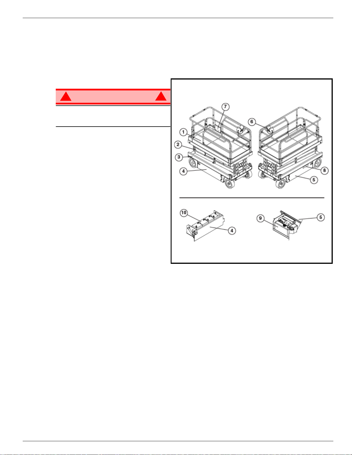
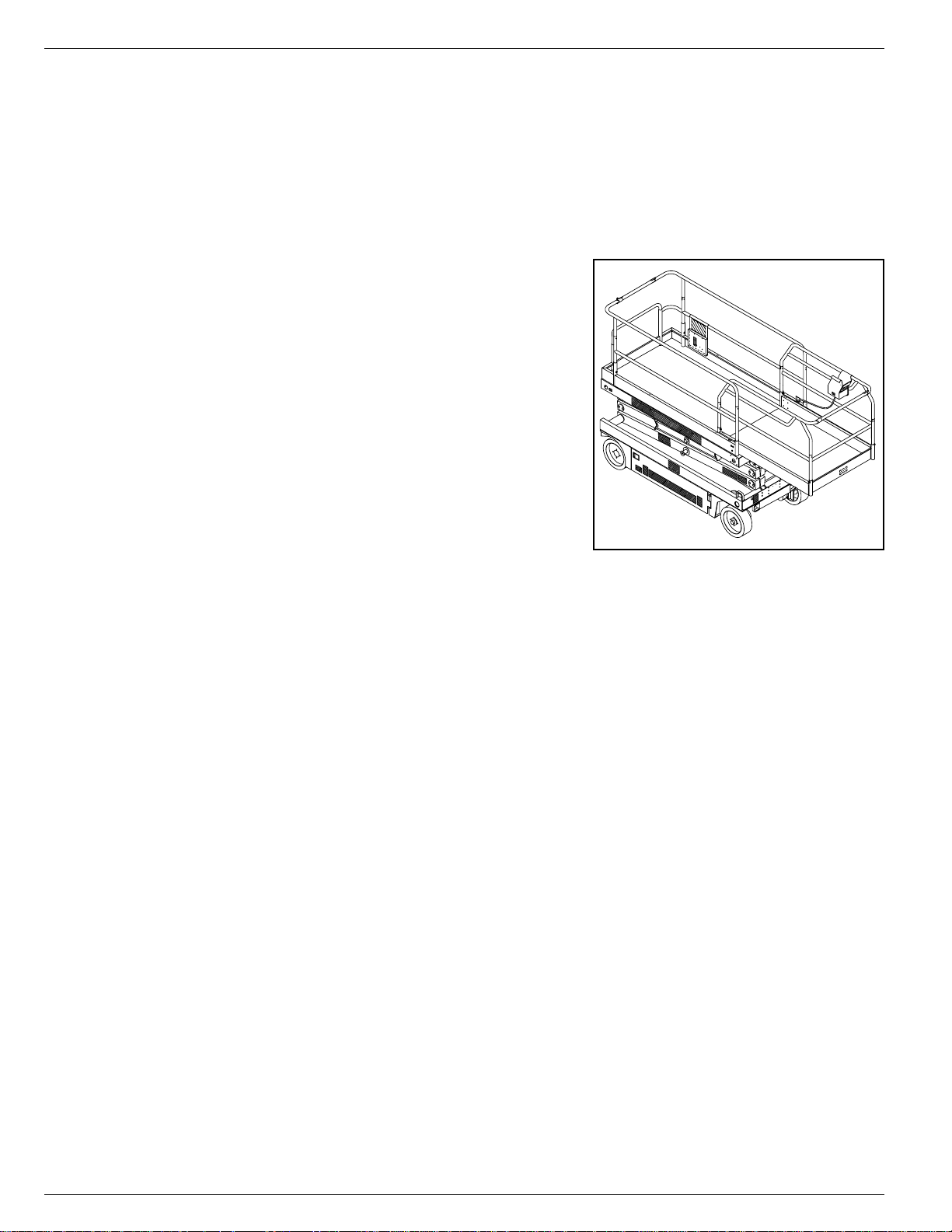
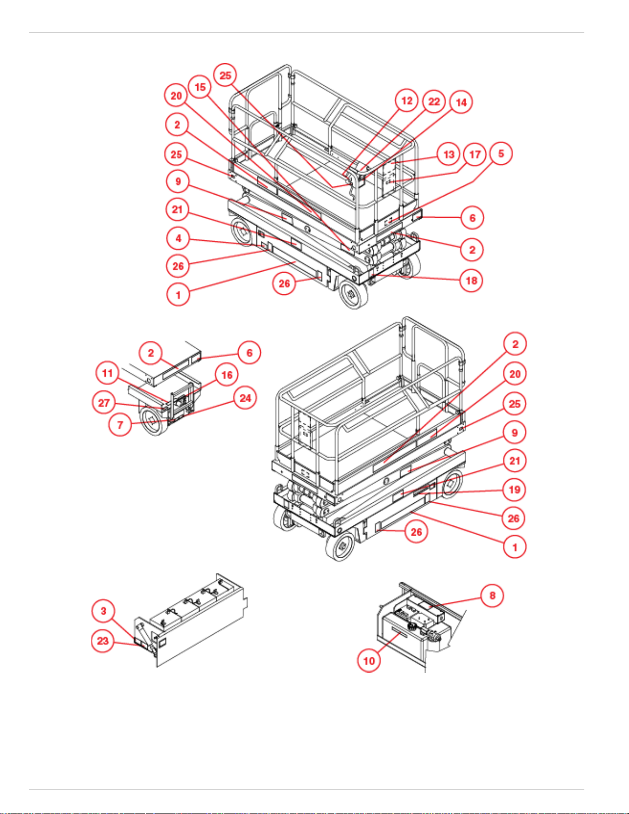
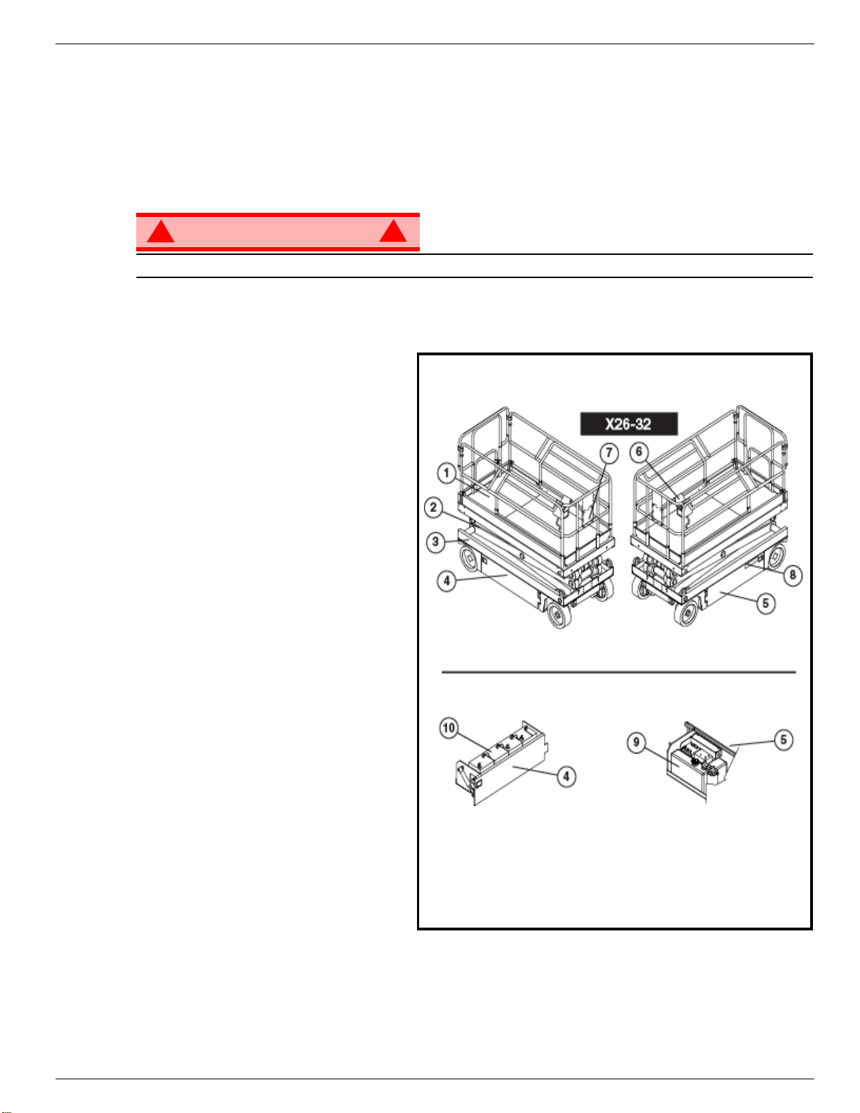
Figure 1: X 26-32
!
WARNING
DO NOT use the maintenance platform
without guardrails properly assembled
and in place
1. Platform
2. Elevating Assembly
3. Chassis
4. Power Module
5. Control Module
6. Platform Controls
7. Manual Case
8. Chassis Controls
9. Hydraulic Fluid Reservoir
10. Batteries
!
Operation Manual Page 3
504165-002 Special Limitations
S
PECIAL
L
IMITATIONS
Travel with the platform raised is limited to creep speed range.
Elevating the Work Platform is limited to firm, level surfaces only.
DANGER
! !
The elev ating function shall ONLY be used when the work platform is level and on a firm surface.
The work platform is NOT intended to be driven over uneven, rough, or soft terrain.
P
LATFORM
The maximum capacity for the MACHINE, including occupants is determined by model and options, and
is listed in “Decals” on page 18.
DANGER
! !
DO NOT exceed the maximum platform capacity or the platform occupancy limits for this machine.
M
ANUAL
Manual force is t he force applied by the occu pants to objects such a s w alls or other structures outside the
work platform.
F
C
ORCE
APACITY
The maximum allowable manual force is limited to 200 N ( 45 lb s.) of force per occupant, with a ma xim u m
of 400 N (90 lbs.) for two or more occupants.
DANGER
! !
DO NOT exceed the maximum amount of manual force for this machine.
B
EAUFORT
Never op erate the machine when wind speeds exceed 25 km/h (15 mph) [Beaufort scale 4].
BEAUFORT
RATING
3 3,4~5,4 12,25~19,4 11.5~17.75 7.5~12.0 Papers and thin branches move, flags wave.
4 5,4~8,0 19,4~28,8 17.75~26.25 12.0~18 Dust is raised, paper whirls up, and small branches sway.
5 8,0~10,8 28,8~38,9 26.25~35.5 18~24.25 Shrubs with leaves start swaying. Wave crests are apparent in ponds or swamps.
6 10,8~13,9 38,9~50,0 35.5~45.5 24.5~31 Tree branches move. Power lines whistle. It is difficult to open an umbrella.
7 13,9~17,2 50,0~61,9 45.5~56.5 31.~38.5 Whole trees sway. It is difficult to walk against the wind.
m/s km/h ft/s mph
L
IFT
O
If a load equivalent to 90% of safe working load is lifted a fault code “03” will be displayed on the digital
display on the platform control box. If a load which is greater than the safe working load is present in the
basket all machine functions will cease to operate and an acoustic warning will sound. In order to return to
normal operation a load equal to or less than the saf e w orking load must be present in the bask e t and the
power must be re-cycled, power can be re-cycled by pushing the emergency stop button and releasing it
again.
S
WIND SPEED
VERLOAD
CALE
A
GROUND CONDITIONS
LARM
DANGER
! !
Never operate the machine with a platform load greater than the rated capacity.
Page 4 Operation Manual
Controls and Indicators 504165-002
C
ONTROLS
AND
I
NDICATORS
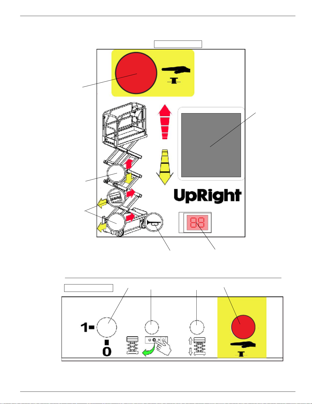
Figure 2: Controls and Indicators
Platform Controls
4
6
3
1
1Drive Selectors
2. Horn Button
3. Lift/Lower Button
4. Emergency Stop Button
5. Display
6. Joystick
Chassis Controls
2
1
234
5
1. Keyswitch
2. Enable Button
3. Toggle Switch (Up & Down)
4. Emergency Stop Switch
Operation Manual Page 5
504165-002 Pre-Operation Safety Inspection
P
RE
-O
PERATION
NOTE: Carefully read, understand and follow all safety rules, operating instructions, labels and National Safety
Instructions/Requirements. Perform the following steps each day before use.
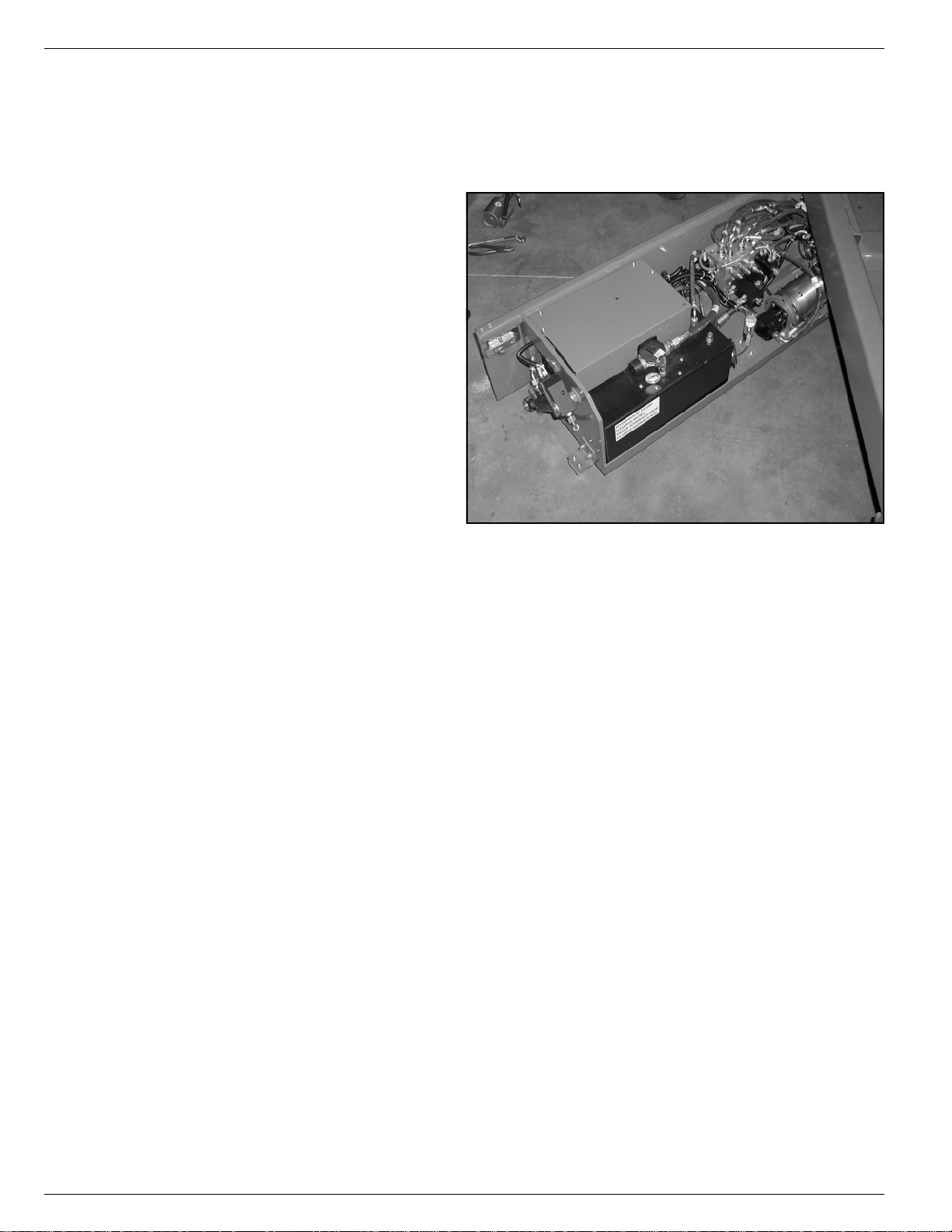
1. Open modules and inspect for damage, fluid leaks or missing parts.
2. Check the lev el of the h ydrau lic fluid with
the platform fully lowered. The hydraulic
reservoir is located in the Control Module Door. The fluid level must be
between the MIN and MAX lines. Add
hydraulic fluid if necessary.
3. Check that fluid level in the batteries is
correct.
4. Verify that batteries are charged.
5. Check that A.C. extension cord has
been disconnected from the plug in the
rear of the machine.
6. Check that all guardrails are in place
and all fasteners are properly tightened.
7. Inspect the machine thoroughly for
cracked welds and structural damage,
loose or missing hardware, hydraulic
leaks, damaged control cable, loose wire connections and wheel bolts.
S
AFETY
I
NSPECTION
Figure 3: Hydraulic Tank
Page 6 Operation Manual

System Function Inspection 504165-002
S
YSTEM
F
UNCTION
Refer to Figure 2 for the locations of various controls and indicators.
I
NSPECTION
!
WARNING
STAND CLEAR of the work platform while performing the following checks.
Before operat ing the work platform, survey the work area for surface hazards such as holes, drop-offs,
bumps and debris.
Check in ALL directions, including above the work platform, for obstructions and electrical cond u cto rs.
Protect the control console cable from possible damage while performing checks.
1. Move the machine, if necessary, to an unobstructed area to allow for full elevation.
2. Pull Chassis Emergency Stop Switch to the ON position.
3. Pull Platform Emergency Stop Switch to the ON position.
4. Turn and hold the Chassis Key Switch to the ON position. Push the Chassis Lift/Lo w e r Switch to th e UP
position and raise the platf orm approximately 2,1 m (7 feet). BLOCK THE ELEVATING ASSEMBLY AS
DESCRIBED ON PAGE 9.
5. Visually inspect the elevating assembly, lift cylinder, cables, and hoses for cracked welds and structural
damage, loose hardware, hydraulic leaks, loose wire connections, and erratic operation. Check for missing or loose parts.
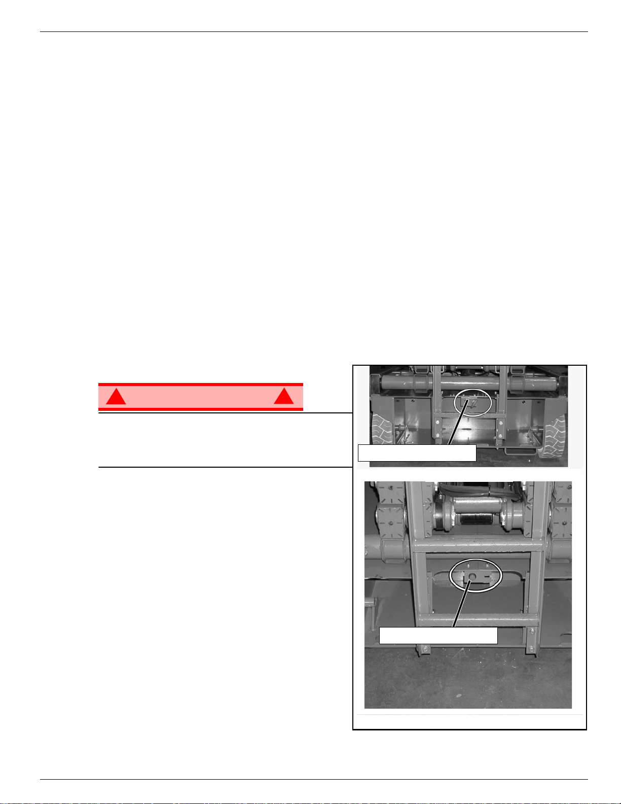
6. V erify that the Depression Mechanism Supports hav e rotated into position under t he machine . REMOVE
THE SCISSOR BRACE AS DESCRIBED ON page 13.
7. Push the Chassis Lift/Lower Switch to the UP position and fully elevate the platform.
8. Partially lower the platform by pushing Chassis Lift/Lower Switch to LOWER, and check for proper operation of the audible lowering alarm.
9. Open the Emergency Lowering Valve (see Figure 5) by pulling the knob out to check for proper operation. When the platform is low ered, release the knob.
10. Push the Chassis Emergency Stop Switch to check for proper operation. All machine functions should
be disabled. Pull out the Chassis Emergency Stop Switch to resume.
11. Check that the route is clear of obstacles (persons, obstructions, holes, and drop-offs, bumps and
debris), is level, and is capable of supporting the wheel loads.
12. Mount the platform and properly close the entrance.
13. Mount the platform and select DRIVE mode.
!
NOTE: Use both HI and LOW drive (if applicable) when performing the following step.
14. While engaging the Interlock Switch, move the Control Handle to FORWARD, then REVERSE, to check
for speed control.
15. Push the Steering Switch RIGHT, then LEFT, to check for steering control.
16. Select LIFT mode. Grasp the Control Handle, engaging the Interlock Switch, and push it forward to
check platform lift controls. Raise the platform to full elevation.
17. Pull back on the Control Handle. The platform should descend and the audible lowering alarm should
sound.
18. Push the Platform Emergency Stop Switch to check for proper operation. All machine functions should
be disabled. Pull out the Platform Emergency Stop Switch to resume.
Operation Manual Page 7
504165-002
O
PERATION
Before operating t he wo rk platform, ensure that the Pre-Operation Safety Inspection has been comple ted
and that any deficiencies ha v e been cor rected. Ne ver opera te a dama ged or malfunctioning mac hine.
The operator must be thoroughly tr ained on this machine.
P
LATFORM
1. Mount the platform and properly close the entrance.
2. Depress the foot lever located at the rear of the platform
extension. Push the platform extension forward until the
pin engages the front stop.
3. To retract the platform extension, depress the foot lever
and pull the platform extension toward the rear of the
machine until the pin engages the rear stop.
T
RAVEL
OWERED
L
1. Check that the route is clear of ob stacles (persons,
obstructions, holes, drop-off s, b umps , and debris), is le v el,
and is capable of supporting the wheel loads.
2. V erify that the Chassis K e y Switch is turned to ON and the
Chassis Emergency Stop Switch is ON (pulled out).
3. Mount the platform and properly close the entrance.
4. Check clearances above, below, and to the sides of platform.
5. Pull the Platform Emergency Stop Switch out to the ON position.
6. Select DRIVE mode.
W
E
XTENSION
ITH THE
P
LATFORM
Figure 4: Platform Extension
NOTE: Choose between standard drive and extra torque depending on the gradient.
7. Engage the Interlock Switch and move the Control Handle to FORWARD or REVERSE to travel in the
desired direction. The speed of the machine will vary depending on how far from centre the Control
Handle is moved.
S
TEERING
1. Turn the Drive/Lift Switch to DRIVE.
2. While engaging the Interlock Switch, push the Steering Switch to RIGHT or LEFT to tu rn the wheels in
the desired direction. Observe the tire s while manoeuvring the work platform to ensure proper direction.
NOTE: Steering is not self-centring. Wheels must be returned to the straight ahead position by operating the Steering
Switch.
E
LEVATING
1. Select a firm, level surface.
2. Select LIFT mode.
3. While engaging the Interlock Switch, push the Control Handle forward.
4. If the machine is not level the tilt alarm will sound and the machine will not lift or drive. If the tilt alarm
sounds the platform must be lowered and the machine moved to a firm level surface before
attempting to re-elevate the platform.
NOTE: Depression Mechanism supports will deploy automatically as the platform elevates and will retract after the
platform has been lowered completely and has been driven.
THE
P
LATFORM
Page 8 Operation Manual
Operation 504165-002
T
RAVEL
NOTE: The machine will travel at reduced speed when the platform is elevated.
1. Check that the route is clear of obsta cles (persons , obstructions, ho les, drop- offs, b umps , and debris), is
level, and is capable of supporting the wheel loads.
2. Check clearances above, below, and to the sides of platform.
3. Select DRIVe mode.
4. Engage the Interlock Switch and move the Control Handle to FORWARD or REVERSE to travel in the
desired direction. The speed of the machine will vary depending on how far from centre the Control Handle is moved.
5. If the machine is not level the tilt alarm will sound and the machine will not lift or drive. If the tilt alarm
sounds the platform must be lowered and the machine moved to a firm, level surface before
attempting to re-elevate the platform.
L
OWERING
1. Select LIFT mode.
2. Check around the base of the platform to ensure that no one is in contact with the machine. Engage the
Interlock Switch and pull back on the Control Handle to lower the platform.
3. The platform will stop when it reaches the PPE cutout height. Inspect around the machine to ensure no
one is in contact with the machine. After a four-second time delay, lower the platform as in step 2.
W
ITH THE
THE
P
P
LATFORM
LATFORM
E
LEVATED
E
MERGENCY
!
WARNING
If the platform should fail to lower, NEVER climb
down the elevating assembly.
Stand clear of the elev ating assembly while oper ating
the Emergency Lowering Valve Knob.
L
OWERING
!
X26
The Emergency Lowering Valve for the X26 is
located at the rear of the machine, above the
charger.
1. Open the Emergency Lowering Valve by pulling
and holding the knob.
2. To close, release the knob. The platform will not
elevate if the Emergency Lowering Valve is open.
X32
The emergency lowering control s witch is located at
the rear of the machine.
Figure 5: Emergency Lowering Valve
Emergency Lowering Knob
X 26
Emergency Lowering Button
1. Open the emergency lowering valve by pushing
down on the toggle switch and holding it.
2. Once the platform is fully lowered, release the
toggle switch to close the valve. The platform will
not elev ate if the Emergency Lowering Valve is
open.
Operation Manual Page 9
X 32

504165-002 Operation
L
OWER
This procedure applies only to the X26 model for the purpose of passing through a standard double doorway. Guardrails must be returned to proper position before using the machine.
L
OWERING PROCEDURE
1. Ensure that the slide-out deck extension is fully retracted and the dec k pin is loc k e d. Place the Platform
Controls on the floor of the platform.
2. Remove and retain the set screws from the side guardrails and the slide-out deck guardrails.
3. Lower the slide-out deck guardrail completely.
4. Lower the rear guardrail until it rests on the stop screws.
5. Lower the side guardrails completely.
6. Raise the rear guardrail until the retaining pins engage. Remove and retain the stop screws and nuts
from the rear guardrail.
7. Pull the two retaining pins and lower the rear guardrail completely.
R
AISING PROCEDURE
1. Raise the rear guardrail until the retaining pins engage.
2. Install the stop screws and nuts on the rear guardrail and torque to 42 N-m (31 ft. lbs).
3. Pull the two retaining pins and lower the rear guardrail until it rests on the stop screws.
4. Raise the side guardrails until the tops are level with the rear guardrail.
• Install the set screws
5. Raise the slide-out deck guardrail until the top is level with the side guardrails.
• Install the set screws
6. Hang the controller on the slide-out deck guardrail.
7. Torque all set screws to 42 N-m (31 ft. lbs).
THE
G
UARDRAILS
, X26
!
WARNING
Before operating machine, guardrails must be securely fastened in their proper position.
F
OLD
F
OLD
1. Unhook the controller from the side guardrail and place it on the floor of the platform.
2. Pull the retaining pin on the front guardrail and rotate inwards.
3. Pull the retaining pin on the rear guardrail and rotate inwards.
4. Starting with the slide-out deck guardrails and then the outer guardrails, lift up on each guardrail and
E
RECTION PROCEDURE
1. Starting with the outer guardrails and then the slide-out de ck guardr ails , raise each guardrail and d rop it
2. Rotate the front and rear upper guardrails outward and secure them to the opposite side guardrails,
3. Hang the controller on the side guardrail.
D
OWN GUARDRAILS
This procedure applies only to the X32 model for the purpose of passing through a standard double doorway. Guardrails must be returned to proper position before using the machine.
D
OWN PROCEDURE
fold inward.
down, securing it in the vertical position.
using the retaining pins.
!
, X32
Page 10 Operation Manual

Towing or Winching 504165-002
T
OWING
OR
W
INCHING
Perform the following only when the machine will not operate under its own power and it is necessary to
move the machine or when winching onto a transport vehicle (see “Transporting the Work Platform” on
page 11).
CAUTION
DO NOT tow or winch the machine faster than 0,3 m/s (1 ft./s). Faster speeds will damage drive
components and void the warranty.
!
WARNING
Never tow faster than 0,3 m/sec. (1 ft./sec.).
Never op erate the work platform with the parking brakes released. Serious injury or damage could
result.
A
FTER
1. Ensure that the platform is fully lowered.
2. Park the machine on a firm level surface, preferably under cover, secure against vandals, children and
3. Turn the Chassis Key Switch to OFF and remove the key to prevent unauthorized operation.
H
OUR
To access the hour meter function perform the following steps.
1. Climb into the basket (with the machine powered up)
2. Push the platform emergency stop button.
3. Hold down the following buttons, Jib and Upper Boom Lift.
4. While holding the buttons twist the emergency stop button to return power to the machine.
5. “hr” will now be displayed on the read-out, Pressing the right turn button will scroll through the accumulated hours two digits at a time. F o r e xample , if pressing the right turn button once displa ys “20”, pressing it
a 2nd time displays “58”, and pressing it a 3rd time displays “hr”, the elapsed time of operation is 2058
hours.
U
SE
E
ACH
unauthorized operation.
M
ETER
D
!
AY
T
RANSPORTING
P
REPARATION
1. Fully lower the platform.
2. Disconnect the battery negative (-) lead from the battery terminal.
3. Band the controller to the front guardrail.
4. Band the elevating linkage to the frame.
Operation Manual Page 11
THE
W
FOR
ORK
S
P
LATFORM
HIPMENT
504165-002 Transporting the Work Platform
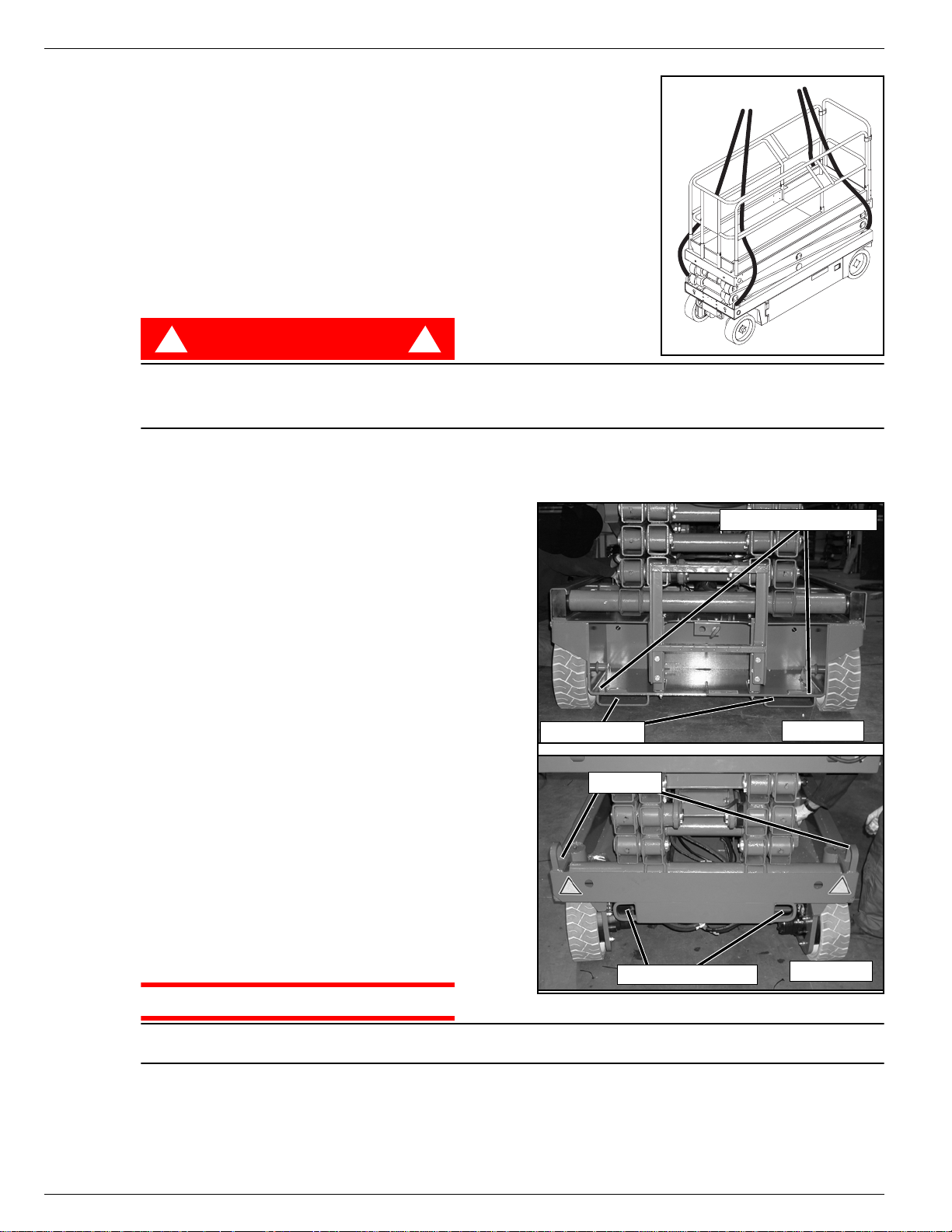
Figure 6: Secure Crane Straps
L
IFTING
1. Secure straps to chassis tie down/lifting lugs only.
2. Place the platform onto the transport vehicle in transport position.
3. Chock the wheels.
4. Secure the work platform to the transport vehicle with chains or
straps of adequate load capacity attached to the cha ssis tie down/lifting lugs.
BY C
RANE
BY F
Forklifting is for transport only.
See specifications for weight of work platform and be certain that forklift is of adequate capacity to lift
the work platform.
D
A
T
NOTE: Do not winch faster than 0,3 m/s (1 ft/s).
1. Move the machine onto the truck or trailer;
2. Secure the work platform to the transport vehicle
ORKLIFT
DANGER
! !
Forklift from the rear of the machine using the forklift pockets provided. If necessary, the machine ma y be
forklifted from the side by lifting under the Chassis Modules.
Figure 7: Transporting the Work Platform
RIVING OR
RUCK
A. To Drive the machine onto the transport vehicle:
a. Move the work platform up the ramp and into
transport position.
b. Set the wheels straight and turn off the machine.
c. Chock the wheels.
B. To Winch the machine onto the transport vehi-
cle:
a. Move the work platform up to the ramp.
b. Attach the winch cable to the tie down/lifting
lugs.
c. Release the parking brakes (refer to “Towing or
Winching” on page 11).
d. Winch the platform into transport position
e. Chock the wheels.
with chains or straps of adequate load capacity
attached to the chassis tie down/lifting lugs.
W
INCHING
OR
T
RAILER
ONTO
Forklift Pockets
Lift Lugs
Rear Tie Down/Lift Lugs
REAR
Front Tie Down Lugs
FRONT
CAUTION
Over tightening of the chains or straps attached to the Tie Down/Lifting Lugs may result in damage to
work platform.
Page 12 Operation Manual
Maintenance 504165-002
M
AINTENANCE
!
WARNING
Never pe rform service while the platform is elevated without first blocking the elevating assembly.
DO NOT stand in the elevating assembly area while deploying or storing the brace.
B
LOCKING
SSEMBLY
A
S
CISSOR BRACE INSTALLATION
1. Park the work platform on a firm, level surface.
2. Pull Chassis EMERGENCY STOP Switch to the ON position.
3. Pull Platform EMERGENCY STOP Switch to the ON position.
4. Turn and hold the Chassis Key Switch to CHASSIS.
5. Push the Chassis Lift/Lower Switch to LIFT to elevate the
platform until the Scissor Brace can be rotated to the vertical
position.
6. X26 – From the rear of the machine, lift the Scissor Brace
from its stowed position. Rotate upward and outward, then
down until it is hanging vertically below its attachment point.
7. X32 – From the left side of the machine, pull the locking pin
securing the brace. Rotate the Scissor Brace counter clockwise until it is in the vertical position.
8. Lower the platform by pushing the Chassis Lift/Lower Switch
to LOWER and grad ually lower the platform until the Scissor
Brace is supporting the platform.
T
HE
E
LEVATING
!
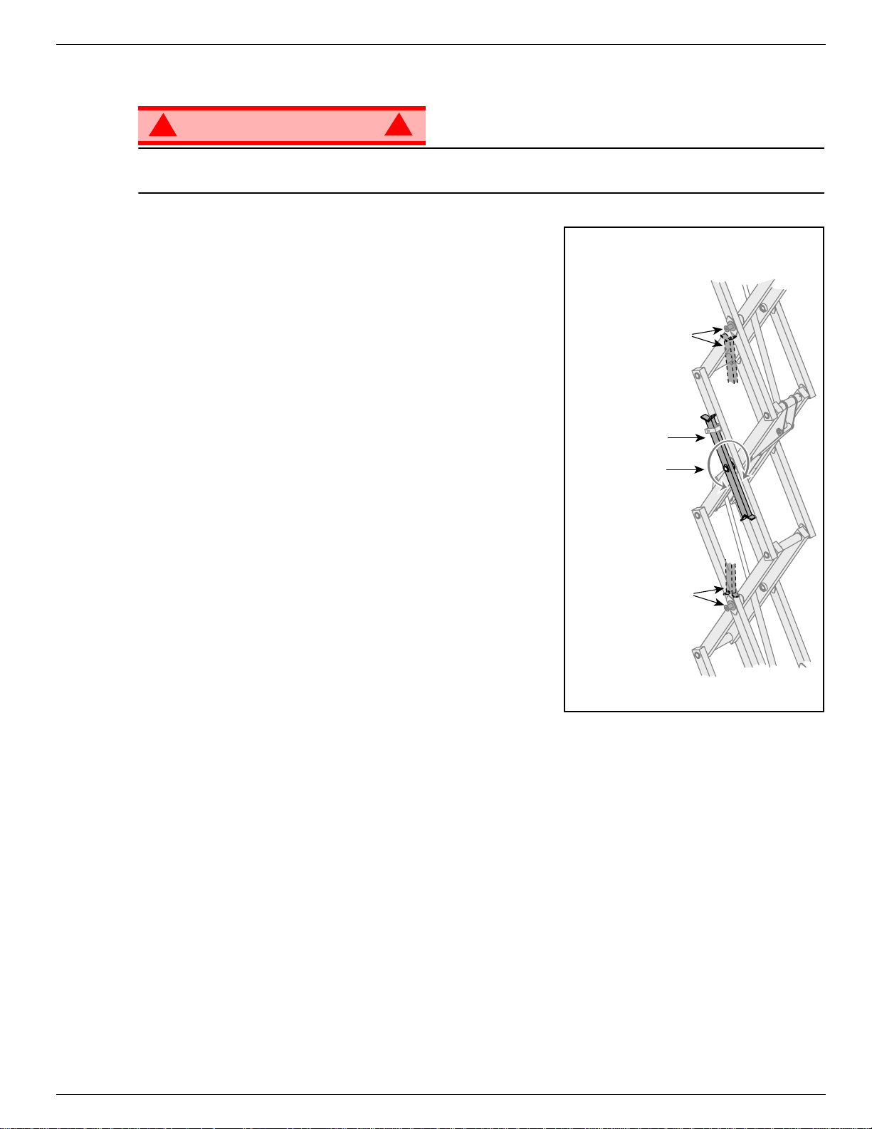
Figure 8: Scissor Brace
Pin Rests on Brace
when in Blocking
Position
Scissor Brace in
Rest Position
Brace Rotates to
Blocking Position
Brace Rests on Pin
when in Blocking
Position
S
CISSOR BRACE
1. Using the Chassis Controls, gradually elevate the platform
until the Scissor Brace is clear.
2. X26 – Rotate the Scissor Brace outward and upward over its mounting point until it rests in the stowed
position.
3. X32 – Rotate the Scissor Brace clockwise until the locking pin engages.
4. Lower the platform by pushing the Chassis Lift/Lower Switch to LOWER to completely lower the platform.
S
TOWAGE
Operation Manual Page 13
504165-002 Maintenance
B
ATTERY
M
AINTENANCE
!
WARNING
Hazard of explosive gas mixture. Keep sparks, flame, and smoking material away from batteries.
Always wear safety glasses when working near batteries.
Battery fluid is highly corrosive. Thoroughly rinse away any spilled fluid with clean water.
Always replace batteries with UpRight batteries or manufacturer approved replacements weighing
26,3 kg (58 lbs.) each.
• Check the battery fluid lev el daily, especially if the work platform is being used in a warm, dry climate.
• If electrolyte level is lower than 10 mm
tap water with high mineral content, as it will shorten battery life.
• Keep the terminals and tops of the batteries clean.
• Refer to the Service Manual to extend battery life and for complete service instructions.
B
ATTERY CHARGING
Charge the batteries at the end of each work
shift or sooner if the batteries have been discharged.
!
WARNING
Charge the batteries in a well ventilated area.
Do not charge the batteries when the work
platform is near a source of sparks or flames.
Permanent damage to the batteries will result if
the batteries are not immediately recharged
after discharging.
Never leave the battery charger operating for more than two days.
Never disconnect the cables from the batteries when the charger is oper ating.
Keep the charger dry.
!
3
(
/
in.) above the plates add distilled water only. DO NOT use
8
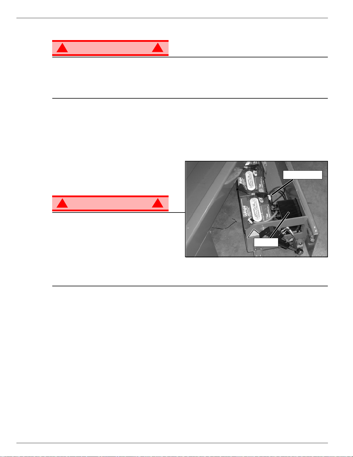
Figure 9: Battery Charger
Charger Plug
!
Charger
3
(
/
1. Check the battery fluid level. If the battery fluid level is lower than 10 mm
distilled water only.
2. Connect an appropriate extension cord to ch arger outlet plug in Left Module Door. Plug the extension
cord into a properly grounded outlet of proper voltage and frequency.
3. The charger turns on automatically after a short delay. The LED charge indicator will illuminate. After
completion of the charge cycle the LED will blink, indicating that the charger is in a continuing maintenance mode. DO NO T leave the charger plugged in for more than 48 hours, as permanent damage to
the batteries may occur.
NOTE: The battery charger circuit must be used with a GFI (Ground Fault Interrupt) outlet.
NOTE: DO NOT operate the machine while the charger is plugged in.
Page 14 Operation Manual
in.) above the plates add
8
Inspection and Maintenance Schedule 504165-002
I
NSPECTION
The Complete Inspection consists of periodic visual and operational checks, along with periodic minor
adjustments that assure proper performance. Daily inspection will prevent abnormal wear and prolong the
life of all systems. The inspection and maintenance schedule should be performed at the specified intervals. Inspection and maintenance shall be performed by personnel who are trained and familiar with
mechanical and electrical proced u re s.
AND
M
AINTENANCE
S
CHEDULE
D
AILY
M
AINTENANCE
Y = Yes/Acceptable
N = No/Not Acceptable
R = Repaired/Acceptable
!
WARNING
Before performing preventative maintenance, familiarize yourself with the operation of the machine.
Always block the elevating assembly whenever it is necessary to perform maintenance while the
platform is elevated.
The daily preventative maintenance chec klist has been designed for machine service and maintenance.
Please photocopy this page and use the checklist when inspecting the machine.
P
REVENTATIVE
T
ABLE KEY
M
!
AINTENANCE
P
Date:_______________________________________
Owner: _____________________________________
Model No:___________________________________
Serial No: ___________________________________
C
HECKLIST
REVENTATIVE MAINTENANCE
R
EPORT
COMPONENT INSPECTION OR SERVICES Y N R
Battery
Chassis
Control Cable
Controller Check switch operation.
Drive Motors Check for operation and leaks.
Elevating
Assembly
Emergency
Lowering System
Entire Unit Check for and repair collision damage.
Check electrolyte level.
Check battery cable condition.
Check hoses for pinch or rubbing points.
Check welds for cracks.
Check the exterior of the cable for pinching,
binding or wear.
Inspect for structural cracks.
Operate the emergency lowering valve and check
for serviceability.
Serviced By:_________________________ ________
COMPONENT INSPECTION OR SERVICES Y N R
Hydraulic Fluid Check fluid level.
Hydraulic Pump Check for hose fitting leaks.
Hydraulic System Check for leaks.
Labels
Platform Deck
and Rails
Platform Deck
and Rails
Tyres and Wheels Check for damage.
Check for peeling, missing, or unreadable labels
& replace.
Check welds for cracks.
Check condition of deck.
Operation Manual Page 15

504165-002 Daily Preventative Maintenance Checklist
N
OTES
:
Page 16 Operation Manual
Decals 504165-002
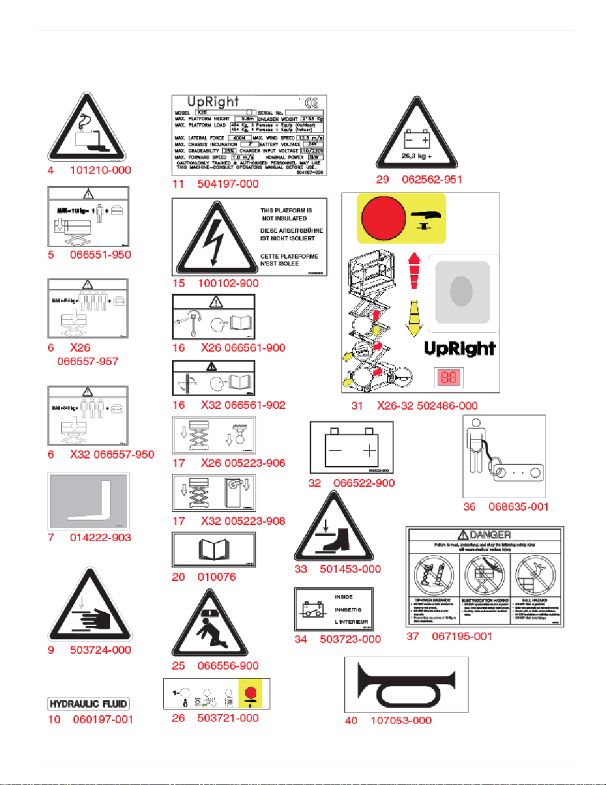
D
ECALS
These labels shall be present and in good condition before operating the work platform. Be sure to read,
understand and follow these labels when operating the work platform.
Operation Manual Page 17
504165-002 Decals
D
ECALS
Page 18 Operation Manual

Specifications 504165-002
S
PECIFICATIONS
ITEM X26 X32
Platform Size w/ Extension
Max. Platform Capacity
Standard 454 kg [1000 lb] 340 kg [750 lbs.]
on Extension 113 kg [250 lb] 113 kg [250 lbs.]
Max. No. of occupants
Standard (total) 4 personas
on Extension 1 persona 1 person
Height
Working Height 9,93 m [32,58 pies] 11.6 m [38.1 ft.]
Max. Platform Height 7,93 m [26 pies] 9.75 m [32 ft.]
Min. Platform Height 1,09 m [43 pulg.] 1.22 m [48 in.]
Dimensions
Weight 2153 kg [4747 lb] 2486 kg [5481 lbs.]
Overall Width 1,22 m [48 pulg.] 1.22 m [48 in.]
Overall Height 2,19 m [83,5 pulg.] 2.32 m [88.5 in.]
Overall Height, Rails Lowered 1,98 m [78 pulg.] 1.88 m [74 in.]
Overall Length, Extension In 2,35 m [92,5 pulg.] 2.35 m [92.5 in.]
Overall Length, Extension Out 3,26 m [128,5 pulg.] 3.26 m [128.5 in.]
Drivable Height 7,93 m [26 pies] 9.75 m [32 ft.]
Drive Speed
Platform Lowered 0 to 3,2 km/h [0 to 2.0 mph]
Platform Raised 0 to 1 km/h [0 to 0.62 mph]
Energy Source
Motor 24 Volt 4 Horse Power DC Electric Motor
System Voltage 24 Volt DC
Battery Charger 25 A, 110/220 V AC
Battery Duty Cycle 25% for 8 Hours
Hydraulic Tank Capacity 15 L [4 US Gallons] 19 L [5 US Gallons]
Maximum Hydraulic Pressure 207 bar [3000 psi]
Hydraulic Fluid
Normal Temperature (>32° F [0° C])
Low Temperature (<32° F [0° C])
Extreme Temperature (<0° F [-17° C])
Lift System
Lift Speed Raise, 45 sec./Lower 40 sec. Raise, 65 sec./Lower 40 sec.
Control System
Drive System Dual Front Wheel Hydraulic Motors
Tires 381 mm [15 in.] Diameter Solid Rubber, non-marking
Parking Brake Dual Spring Applied, Hydraulic Release
Turning Radius 203 mm [8 in.] Inside
Maximum Gradeability 12° [22%] 12° [22%]
Wheel Base 1.9 m [74.75 in.]
Guardrails 1.02 m [40 in.] High
Noise Level
Proportional Control Handle with Interlock Switch, Rotary Drive/Lift Switch,
1,17 m x 2,21 m
[44,25 pulg. x 87 pulg.]
2 personas en el exterior
24 Volt Battery Pack (4-220 A Hour, 6 Volt Batteries, min. wt. 28.12 kg
[62 lbs.] each)
ISO #46
ISO #32
ISO #15
One Single Stage
Lift Cylinder
and Red Mushroom EMERGENCY STOP Switch
1.17 m x 2.21 m
[44 in. x 87 in.]
3 people
Two Single Stage
Lift Cylinders
*Specifications are subject to change without notice. Hot weather or he avy use may affect performance.
Refer to the Service Manual for complete parts and service information.
This machine meets or exceeds all applicable CE and GS machinery directive requirements.
Operation Manual Page 19

504165-002 Specifications
Page 20 Operation Manual
X 26-32
X26 Seriennummern 50906 – 53099
X32 Seriennummern 50322 – 53099
DEUTSCH
Stellen Sie sicher, dass Sie die MODELL- und SERIENNUMMERN auf dem Gerätetypenschild angeben, wenn Sie sich
mit UpRight bezüglich Wartungs- oder Ersatzteilinformationen in Verbindung setzen. Sollte das Typenschild fehlen, finden
Sie die SERIENNUMMER auch auf dem Fahrwerk über der vorderen Schwenkachse.
Stamped Serial Number
Estampille de numéro de série
Eingestanzte Seriennummer


BETRIEBSANLEITUNG
S
WARNUNG
Alle Bediener müssen die Sicherheitsregeln und Betriebsanleitungen gründlich durchlesen,
verstehen und befolgen, bevor sie an irgendeiner UpRight-Hocharbeitsbühne Wartungsarbeiten
ausführen oder die Arbeitsbühne in Betrieb nehmen.
Sicherheitsregeln
Elektroschockgefahr Kippgefahr Kollisionsgefahr
DIESE MASCHINE IST NICHT
ISOLIERT!
EINSATZ DER HOCHARBEITSBÜHNE: Diese Hocharbeitsbühne dient dazu, Personen und Werkzeuge sowie die für die jeweilige Arbeit
erforderlichen Materialien zu transportieren. Sie wurde speziell für Reparatur- und Montagearbeiten sowie für Einsatzbereiche konzipiert, die
sich oberhalb der Mitarbeiter befinden, sodass die Mitarbeit er nach oben gerichtet arbeiten müssen (z. B. Decken, Kräne, Dachstrukturen,
Gebäude etc.). Jede andere Verwendung der Hocharbeitsbühne ist strikt verboten!
DIESE HOCHARBEITSBÜHNE IST NICHT ISOLIERT! Aus diesem Grund muss zwingend ein Sicherheitsabstand zu allen leitfähigen Teilen
der elektrischen Ausrüstung eingehalten werden!
Die angegebene zulässige Höchstlast darf nic ht überschritten w erd en!Nä here Informationen hierzu finden Sie im Abschnitt “Beschränkungen”
auf Seite 4.
Es ist strikt verboten, die Hocharbeitsbühne als Hubwerkzeug ode r Kran einzusetzen (d. h. um Lasten von unten nach oben oder von oben
nach unten zu befördern).
Die für diese Maschine zuläss i ge m anu el le Kraf t NIEMALS überschreiten.Nähere Informationen hierzu finden Sie im Abschnitt
“Beschränkungen” auf Seite 4.
Lasten immer gleichmäßig auf der Plattform VERTEILEN.
Vor Inbetriebnahme der Maschine IMMER ZUERST die Aufstellfläche im Arbeitsbereich auf Gefahren wie Bodenlöcher, ausgelaufene
Flüssigkeiten, Bodenerhebungen, Kanten oder Schutt untersuchen und diese umgehen bzw. beseitigen.
Maschine nur auf Oberflächen IN BETRIEB NEHMEN, die die zulässigen Radlasten aufnehmen k önnen.
Maschine NIEMALS in Betrieb nehmen, wenn die tatsächliche Windgeschwindigkeit höher ist als die Windgeschwindigkeit, für die die
Maschine ausgelegt ist. Nähere Informationen hierzu finden Sie im Abschnitt “Beaufort-Skala” auf Seite 4.
IM NOTFALL NOT-AUS-Schalter drücken, um alle strombetriebenen Funktionen zu deaktivieren.
WENN EIN ALARM ERTÖNT, während die Plattform ausgefahren wird, Plattform ANHALTEN und vorsichtig einfahren (absenken). Maschine
auf feste, ebene Oberfläche fahren.
Auf das Schutzgeländer der Plat tform zu klettern, auf Gebäuden, Stahl- oder vorgef ertigten Betonstrukturen zu stehen oder von der Plattform
aus darauf zu klettern etc. ist verboten!
Das Schwingtor oder andere Komponenten des Schutzgeländers zu demontieren ist verboten! Vergewissern Sie sich immer, dass das
Schwingtor geschlossen und sicher verriegelt ist!
Es ist verboten, das Schwingtor geöffnet zu halten (z. B. mit Befestigungsgurten), wenn die Arbeitsplattform ausgefahren wird!
Die Höhe oder Reichweite der Plattform durch Anbringen von Leitern, Gerüsten oder ähnlichen Vorrichtungen zu vergrößern
IMMER ZUERST die Hubvorrichtung blockieren, bevor bei ausgefahrener Plattform Wartungs- oder Instandhaltungsarbeiten an der Maschine
durchgeführt werden.
Maschine vor jedem Gebrauch sorgfältig auf Risse an Schweißstellen, lose oder fehlende Beschläge, Leckagen in der Hydr aulikvorrichtung,
gelöste Kabelverbindungen und beschädigte Kabel oder Schläuche UNTERSUCHEN.
Vor Gebrauch SICHERSTELLEN, dass alle Bezeichn ungsschilder ordnungsgemäß angebracht und vollständig lesbar sind.
NIEMALS eine Maschine benutzen, die beschädigt ist, nicht ordnungsgemäß funktioniert oder deren Bezeichnungsschilder Beschädigungen
aufweisen oder sogar ganz fehlen.
Sicherheitseinrichtungen zu umgehen ist verboten und stellt eine Gef ahr für alle Personen dar , die sich auf der Hocharbeit sbüh ne und in deren
Arbeitsbereich befinden.
Batterien NIEMALS in der Nähe von Funkenquellen oder offenen Flammen aufladen. Beim Auflad en von Batterien wird explosives
Wasserstoffgas freigesetzt.
Änderungen an der Hocharbeitsbühne sind verboten bzw. nur mit ausdrücklicher Genehmigung von
NACH GEBRAUCH ist die Hocharbeit sb ühne gegen unbefug ten Gebr auch durch Dritte zu s ichern. Hierzu müs sen bei de Schlü sselschal ter auf
“Aus” gestellt und die Schlüssel abgezogen werden.
NIEMALS die Plattform ausfahren
oder die Maschine mit ausgefahrener
Plattform fortbewegen, wenn sich die
Maschine nicht auf einer festen,
ebenen Fläche befindet.
Plattform NIEMALS in Position
bringen, ohne vorher sicherzustellen,
dass der Bereich über der Plattform
frei von Hindernissen und anderen
Gefahren ist.
UpRight zulässig.
des Plattformgeländers klettern
und auch nicht darauf stehen
turzgefahr
NIEMALS auf das obere
oder mittlere Gestänge
oder sitzen.
ist verboten
!
Seite 1

504165-002
I
NHALT
Einführung. . . . . . . . . . . . . . . . . . . . . . . . . . . . . . . . . . . . . . . . . . . . . . . . . . . . . . . . . . . . . . . . . . . . . . . . . . .3
Allgemeine Beschreibung . . . . . . . . . . . . . . . . . . . . . . . . . . . . . . . . . . . . . . . . . . . . . . . . . . . . . . . . . . . . . .3
Beschränkungen. . . . . . . . . . . . . . . . . . . . . . . . . . . . . . . . . . . . . . . . . . . . . . . . . . . . . . . . . . . . . . . . . . . . . .4
Tragfähigkeit der Plattform . . . . . . . . . . . . . . . . . . . . . . . . . . . . . . . . . . . . . . . . . . . . . . . . . . . . . . . . . . . . . . . . . . . . 4
Manuelle Kraft. . . . . . . . . . . . . . . . . . . . . . . . . . . . . . . . . . . . . . . . . . . . . . . . . . . . . . . . . . . . . . . . . . . . . . . . . . . . . . 4
Beaufort-Skala. . . . . . . . . . . . . . . . . . . . . . . . . . . . . . . . . . . . . . . . . . . . . . . . . . . . . . . . . . . . . . . . . . . . . . . . . . . . . . 4
Überlastalarm . . . . . . . . . . . . . . . . . . . . . . . . . . . . . . . . . . . . . . . . . . . . . . . . . . . . . . . . . . . . . . . . . . . . . . . . . . . . . . 4
Bedienelemente und Anzeigen . . . . . . . . . . . . . . . . . . . . . . . . . . . . . . . . . . . . . . . . . . . . . . . . . . . . . . . . . .5
Sicherheitsprüfung vor Inbetriebnahme . . . . . . . . . . . . . . . . . . . . . . . . . . . . . . . . . . . . . . . . . . . . . . . . . .6
Überprüfung der Systemfunktionen . . . . . . . . . . . . . . . . . . . . . . . . . . . . . . . . . . . . . . . . . . . . . . . . . . . . . .7
Bedienung . . . . . . . . . . . . . . . . . . . . . . . . . . . . . . . . . . . . . . . . . . . . . . . . . . . . . . . . . . . . . . . . . . . . . . . . . . .8
Plattformverlängerung. . . . . . . . . . . . . . . . . . . . . . . . . . . . . . . . . . . . . . . . . . . . . . . . . . . . . . . . . . . . . . . . . . . . . . . . 8
Fahren mit eingefahrener Plattform. . . . . . . . . . . . . . . . . . . . . . . . . . . . . . . . . . . . . . . . . . . . . . . . . . . . . . . . . . . . . . 8
Lenken. . . . . . . . . . . . . . . . . . . . . . . . . . . . . . . . . . . . . . . . . . . . . . . . . . . . . . . . . . . . . . . . . . . . . . . . . . . . . . . . . . . . 8
Ausfahren der Plattform . . . . . . . . . . . . . . . . . . . . . . . . . . . . . . . . . . . . . . . . . . . . . . . . . . . . . . . . . . . . . . . . . . . . . . 8
Fahren mit ausgefahrener Plattform . . . . . . . . . . . . . . . . . . . . . . . . . . . . . . . . . . . . . . . . . . . . . . . . . . . . . . . . . . . . . 9
Einfahren der Plattform . . . . . . . . . . . . . . . . . . . . . . . . . . . . . . . . . . . . . . . . . . . . . . . . . . . . . . . . . . . . . . . . . . . . . . . 9
Notfallabsenkung. . . . . . . . . . . . . . . . . . . . . . . . . . . . . . . . . . . . . . . . . . . . . . . . . . . . . . . . . . . . . . . . . . . . . . . . . . . . 9
X26. . . . . . . . . . . . . . . . . . . . . . . . . . . . . . . . . . . . . . . . . . . . . . . . . . . . . . . . . . . . . . . . . . . . . . . . . . . . . . . . . . . 9
X32. . . . . . . . . . . . . . . . . . . . . . . . . . . . . . . . . . . . . . . . . . . . . . . . . . . . . . . . . . . . . . . . . . . . . . . . . . . . . . . . . . . 9
Absenken des Schutzgeländers, X26 . . . . . . . . . . . . . . . . . . . . . . . . . . . . . . . . . . . . . . . . . . . . . . . . . . . . . . . . . . . 10
Absenken. . . . . . . . . . . . . . . . . . . . . . . . . . . . . . . . . . . . . . . . . . . . . . . . . . . . . . . . . . . . . . . . . . . . . . . . . . . . . 10
Anheben. . . . . . . . . . . . . . . . . . . . . . . . . . . . . . . . . . . . . . . . . . . . . . . . . . . . . . . . . . . . . . . . . . . . . . . . . . . . . . 10
Einklappen des Schutzgeländers, X32 . . . . . . . . . . . . . . . . . . . . . . . . . . . . . . . . . . . . . . . . . . . . . . . . . . . . . . . . . . 11
Einklappen . . . . . . . . . . . . . . . . . . . . . . . . . . . . . . . . . . . . . . . . . . . . . . . . . . . . . . . . . . . . . . . . . . . . . . . . . . . . 11
Ausklappen . . . . . . . . . . . . . . . . . . . . . . . . . . . . . . . . . . . . . . . . . . . . . . . . . . . . . . . . . . . . . . . . . . . . . . . . . . . 11
Schleppen oder Anheben . . . . . . . . . . . . . . . . . . . . . . . . . . . . . . . . . . . . . . . . . . . . . . . . . . . . . . . . . . . . .12
Lösen der Parkbremse . . . . . . . . . . . . . . . . . . . . . . . . . . . . . . . . . . . . . . . . . . . . . . . . . . . . . . . . . . . . . . . . . . . . . . 12
Nach dem täglichen Gebrauch . . . . . . . . . . . . . . . . . . . . . . . . . . . . . . . . . . . . . . . . . . . . . . . . . . . . . . . . . . . . . . . . 12
Betriebsstundenzähler. . . . . . . . . . . . . . . . . . . . . . . . . . . . . . . . . . . . . . . . . . . . . . . . . . . . . . . . . . . . . . . . . . . . . . . 12
Transport der Arbeitsbühne . . . . . . . . . . . . . . . . . . . . . . . . . . . . . . . . . . . . . . . . . . . . . . . . . . . . . . . . . . .13
Vorbereitung . . . . . . . . . . . . . . . . . . . . . . . . . . . . . . . . . . . . . . . . . . . . . . . . . . . . . . . . . . . . . . . . . . . . . . . . . . . . . . 13
Anheben per Kran. . . . . . . . . . . . . . . . . . . . . . . . . . . . . . . . . . . . . . . . . . . . . . . . . . . . . . . . . . . . . . . . . . . . . . . . . . 13
Per Gabelstapler . . . . . . . . . . . . . . . . . . . . . . . . . . . . . . . . . . . . . . . . . . . . . . . . . . . . . . . . . . . . . . . . . . . . . . . . . . . 13
Fahren oder Heben auf einen LKW oder Anhänger . . . . . . . . . . . . . . . . . . . . . . . . . . . . . . . . . . . . . . . . . . . . . . . . 13
Instandhaltung . . . . . . . . . . . . . . . . . . . . . . . . . . . . . . . . . . . . . . . . . . . . . . . . . . . . . . . . . . . . . . . . . . . . . .14
Blockieren der Hubvorrichtung . . . . . . . . . . . . . . . . . . . . . . . . . . . . . . . . . . . . . . . . . . . . . . . . . . . . . . . . . . . . . . . . 14
Installation der Scherenverstrebung . . . . . . . . . . . . . . . . . . . . . . . . . . . . . . . . . . . . . . . . . . . . . . . . . . . . . . . . 14
Verstauen der Scherenverstrebung. . . . . . . . . . . . . . . . . . . . . . . . . . . . . . . . . . . . . . . . . . . . . . . . . . . . . . . . . 14
Instandhaltung der Batterie . . . . . . . . . . . . . . . . . . . . . . . . . . . . . . . . . . . . . . . . . . . . . . . . . . . . . . . . . . . . . . . . . . . 15
Aufladen der Batterien . . . . . . . . . . . . . . . . . . . . . . . . . . . . . . . . . . . . . . . . . . . . . . . . . . . . . . . . . . . . . . . . . . . 15
Inspektions- und Instandhaltungsplan. . . . . . . . . . . . . . . . . . . . . . . . . . . . . . . . . . . . . . . . . . . . . . . . . . .16
Checkliste der täglichen präventiven Instandhaltungsmaßnahmen. . . . . . . . . . . . . . . . . . . . . . . . . . .16
Bezeichnungsschilder . . . . . . . . . . . . . . . . . . . . . . . . . . . . . . . . . . . . . . . . . . . . . . . . . . . . . . . . . . . . . . . .18
Technische Daten. . . . . . . . . . . . . . . . . . . . . . . . . . . . . . . . . . . . . . . . . . . . . . . . . . . . . . . . . . . . . . . . . . . .20
Seite 2 Betriebsanleitung
Einführung 504165-002
E
INFÜHRUNG
Dieses Handbuch beschreibt Einsatz und Bedienung der selbstfahrenden Arbeitsbühnen der X 26-32.
Das Handbuch muss immer bei der Maschine aufbewahrt werden.
A
LLGEMEINE
B
ESCHREIBUNG
WARNUNG
!
Hocharbeitsbühne NICHT ohne korrekt montiertes und angebrachtes Schutzgeländer verwenden.
1. Plattform
2. Hubvorrichtung
3. Fahrwerk
4. Leistungsmodul
5. Steuermodul
6. Plattform-Bedienelemente
7. Handbuchfach
8. Fahrwerk-Bedienelemente
9. Behälter für Hydraulikflüssigkeit
10. Batterien
!
Abbildung 1: X 26-32
Betriebsanleitung Seite 3
504165-002 Beschränkungen
B
ESCHRÄNKUNGEN
Bei ausgefahrener Plattform kann die Maschine nur im Schleichgang gefahren werden.
Die Arbeitsplattform kann nur auf festen, ebenen Oberflächen ausgefahren werden.
GEFAHR
! !
Die Hubfunktion darf NUR verwendet werden, wenn die Hocharbeitsbühne nivelliert ist und auf einer
festen Oberfläche steht.
Die Hocharbeitsbühne ist NICHT dafür ausgelegt, auf unebenem, grobem oder weichem Gelände
gefahren zu werden.
T
RAGFÄHIGKEIT
Die maximale Tragfähigkeit der MASCHINE, einschließlich P ersonen , hängt vom Modell und verschiedenen
Optionen ab; Sie finden eine entsprechende Liste im Abschnitt “” auf Seite 19.
GEFAHR
! !
Maximale Tragf ähigk eit der Plattf orm oder maximal zulässige P ersonenzah l für diese Maschine NICHT
überschreiten.
DER
P
LATTFORM
M
ANUELLE
Unter manueller Kraft versteht man die Kraft, die die Personen auf der Plattform auf Objekte wie Wände
oder andere Strukturen außerhalb der Arbeits plattform ausüben.
Die maximal zulässige manuelle Kraft ist auf 200 N (45 lbs.) pro Person beschränkt, d. h. maximal 400 N
(90 lbs.), wenn sich zwei oder mehr Personen auf der Plattform befinden.
GEFAHR
! !
Die für diese Maschine maximal zulässige manuelle Kraft NICHT überschreiten.
B
EAUFORT
Niemals die Maschine in Betrieb nehmen, wenn die Windgeschwindigkeit mehr als 25 km/h (15 mph)
[Beaufort-Skala 4] beträgt.
BEAUFORT-WERT
3 3,4~5,4 12,25~19,4 11.5~17.75 7.5~12.0 Papier und dünne Zweige bewegen sich, Fahnen wehen.
4 5,4~8,0 19,4~28,8 17.75~26.25 12.0~18 Staub und Papier wird aufgewirbelt und kleine Zweige schaukeln.
5 8,0~10,8 28,8~38,9 26.25~35.5 18~24.25
6 10,8~13,9 38,9~50,0 35.5~45.5 24.5~31
7 13,9~17,2 50,0~61,9 45.5~56.5 31.~38.5 Ganze Bäume schwanken. Es ist schwierig, gegen den Wind zu gehen.
m/s km/h ft/s mph
Ü
BERLASTALARM
Wenn eine Last angehoben wird, die 90 % der Nennlast ausmacht, erscheint im digitalen Display des
Bedienpultes an der Plattform der Fehlercode “03”. Befindet sich im Fahrkorb eine Last, die höher als die
Nennlast ist, werden alle Maschinenfunktionen blockiert und eine akustische Warnung ertönt. Damit der
normale Betrieb wieder aufgenommen werden kann, muss die Last im Fahrkorb verringert werden,
sodass sie gleich oder niedriger als die Nennlast ist, und die Stromzufuhr zur Maschine muss aus- und
wieder eingeschaltet werden. Das Aus- und wieder Einschalten der Stromversorgung kann durch
Drücken und anschließendes Lösen des Not-Aus-Tasters erfolgen.
WINDGESCHWINDIGKEIT
K
-S
RAFT
KALA
BODEN-/UMGEBUNGSBEDINGUNGEN
Sträucher mit Blättern beginnen zu schaukeln. In Teichen, Sümpfen oder anderen Gewässern
erscheinen Wellenkämme.
Zweige und Äste von Bäumen bewegen sich. Stromleitungen pfeifen. Regenschirme können nur mit
Mühe geöffnet werden.
GEFAHR
! !
Niemals die Maschine in Betrieb nehmen, wenn sich auf der Arbeitsplattform eine Last befindet, die
die angegebene Tragfähigkeit überschreitet.
Seite 4 Betriebsanleitung
 Loading...