

Page 1

Operator Manual
Guide de l’opérateur
Betriebsanleitung
UL25, UL32 & UL40
SERIAL NO. 21373 to Current
WARNING
All personnel shall carefully read, understand and follow all safety rules,
operating instructions, and National Safety Instructions/Requirements
before operating or performing maintenance on any UpRight Aerial Work
Platform.
The first section of this Operator Manual is the English language version.
AVERTISSEMENT
Tout le personnel doit lire attentivement, bien comprendre et suivre toutes
les règles de sécurité, le mode d’emploi et les règles nationales de
sécurité avant d’entretenir ou d’utiliser une plate-forme élévatrice
UpRight.
La deuxième section du guide de l’opérateur est la version française.
WARNUNG
Alle Bediener müssen die Sicherheitsregeln, Betriebsanleitungen sowie
geltenden Sicherheitsanweisungen/-anforderungen gründlich durchlesen,
verstehen und befolgen, bevor sie an irgendeiner UpRightHocharbeitsbühne Wartungsarbeiten ausführen oder diese in Betrieb
nehmen.
Der dritte Abschnitt dieser Betriebsanleitung ist deutschsprachig.
P/N 068017-021
Page 2
UL25,UL32&UL40
Serial Numbers 21373 – Current
E
NGLISH
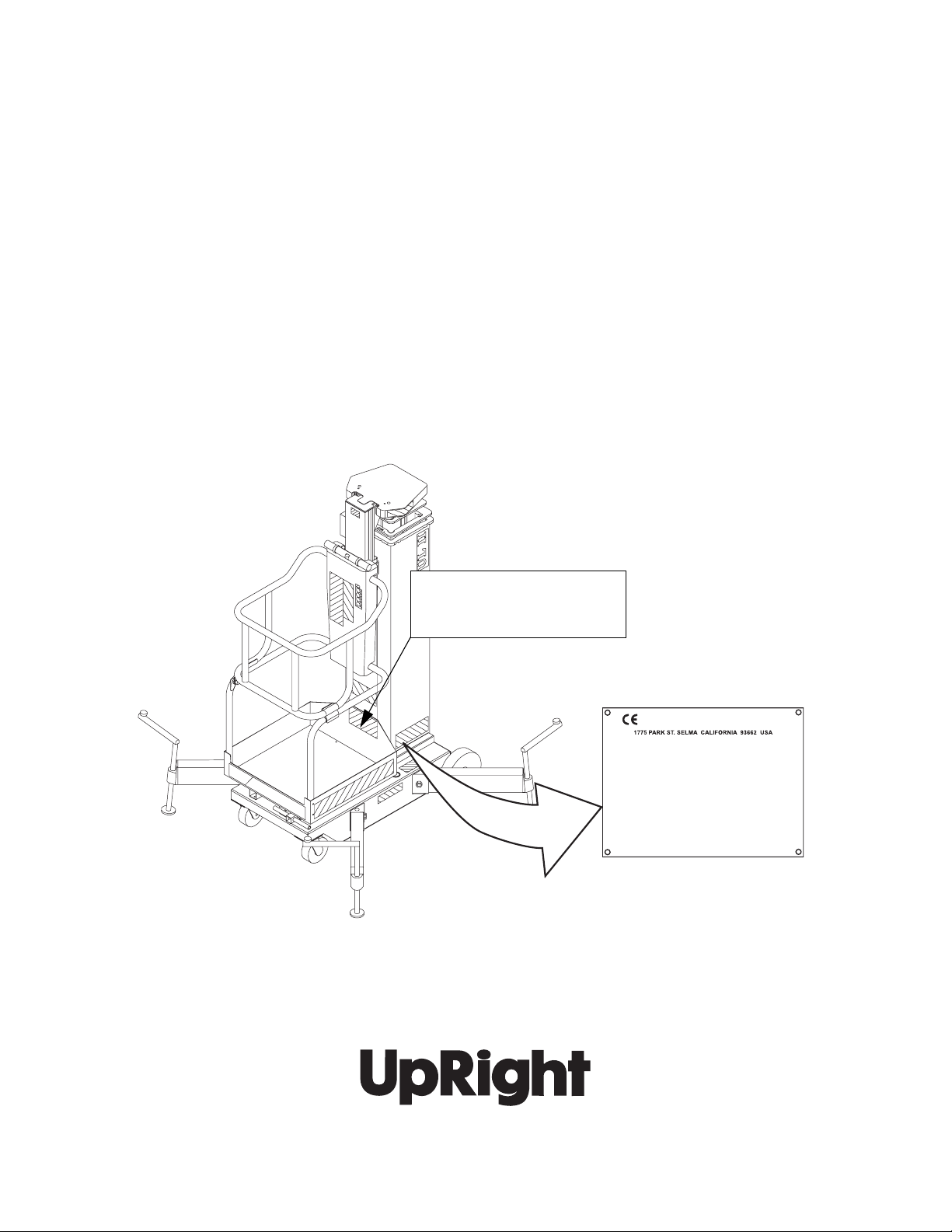
When contacting UpRight for service or parts information, be sure to include the MODEL and SERIAL NUMBERS from the
equipment nameplate. Should the nameplate be missing, the SERIAL NUMBER is also stamped on the chassis tube on the
rightsideofthemast.
F
RENCH
Lors des communications avec UpRight pour des informations au sujet de l’entretient ou des pièces, ne pas oublier
d’inclure les NUMÉROS DE MODÈLE et de SÉRIE inscrits sur la plaque signalétique. Si la plaque signalétique manque, le
NUMÉRO DE SÉRIE est également estampé sur le châssis, du côté droit du mât.
G
ERMAN
Stellen Sie sicher, dass Sie die MODELL- und SERIENNUMMERN auf dem Gerätetypenschild angeben, wenn Sie sich mit
UpRight bezüglich Wartungs- oder Ersatzteilinformationen in Verbindung setzten. Sollte das Typenschild fehlen, finden Sie
die SERIENNUMMER auch auf dem Fahrwerk auf der rechten Maststeite eingestanzt.
UpRight, Inc.
1775 Park Street
Selma, California 93662
TEL: 559/891-5200
FAX: 559/891-9012
PARTS: 1-888-UR-PARTS
PARTS FAX: 559/896-9244
Stamped Serial Number
Estampille de numéro de série
Eingestanzte Seriennummer
Call Toll Free in U.S.A.
1-800-926-LIFT
UpRight Inc.
Model______________ Serial number:___________
Machine weight _______kg Mfg. date:_________
Maximum wheel load:________
Maximum allowable incline of machine when elevated:_____deg.
Occupants and equipment must not exceed the rated maximum
load:_____kg Maximum platform occupant s:_____
Maximum allowable sIde force on platform:_____N
Maximum platformheight:______m
Maximum platform reach:______m
Maximum allowable wind speed: ______m/s=Beaufort scale_ ____
Maximum hydraulic system pressure:_____bar
Maximum system voltage: _______Vdc
This machine is manufactured to comply with
Machinery directive 89-392/CEE
CAUTION: CONSULT OPERATOR'S MANUAL BEFORE USE.
061205-003
UpRight International
Support Centre
61-63 Hong Kong Straat
3047 BR Rotterdam
Netherlands
TEL: +31-10-238-0000
FAX: +31-10-238-0001
Parts Tel: +31-10-490-8090
Parts Fax: +31-10-490-8099
Page 3
OPERATION MANUAL
WARNING
All personnel shall carefully read, understand and follow all safety rules and operating
instructions before operating or performing maintenance on any UpRight aerial work platform.
Safety Rules
Safety Rules
Safety RulesSafety Rules
Electrocution
Electrocution
ElectrocutionElectrocution
Hazard
Hazard
HazardHazard
Tip Over Hazard
Tip Over Hazard Collision Hazard
Tip Over HazardTip Over Hazard
Collision Hazard Fall Hazard
Collision HazardCollision Hazard
Fall Hazard
Fall HazardFall Hazard
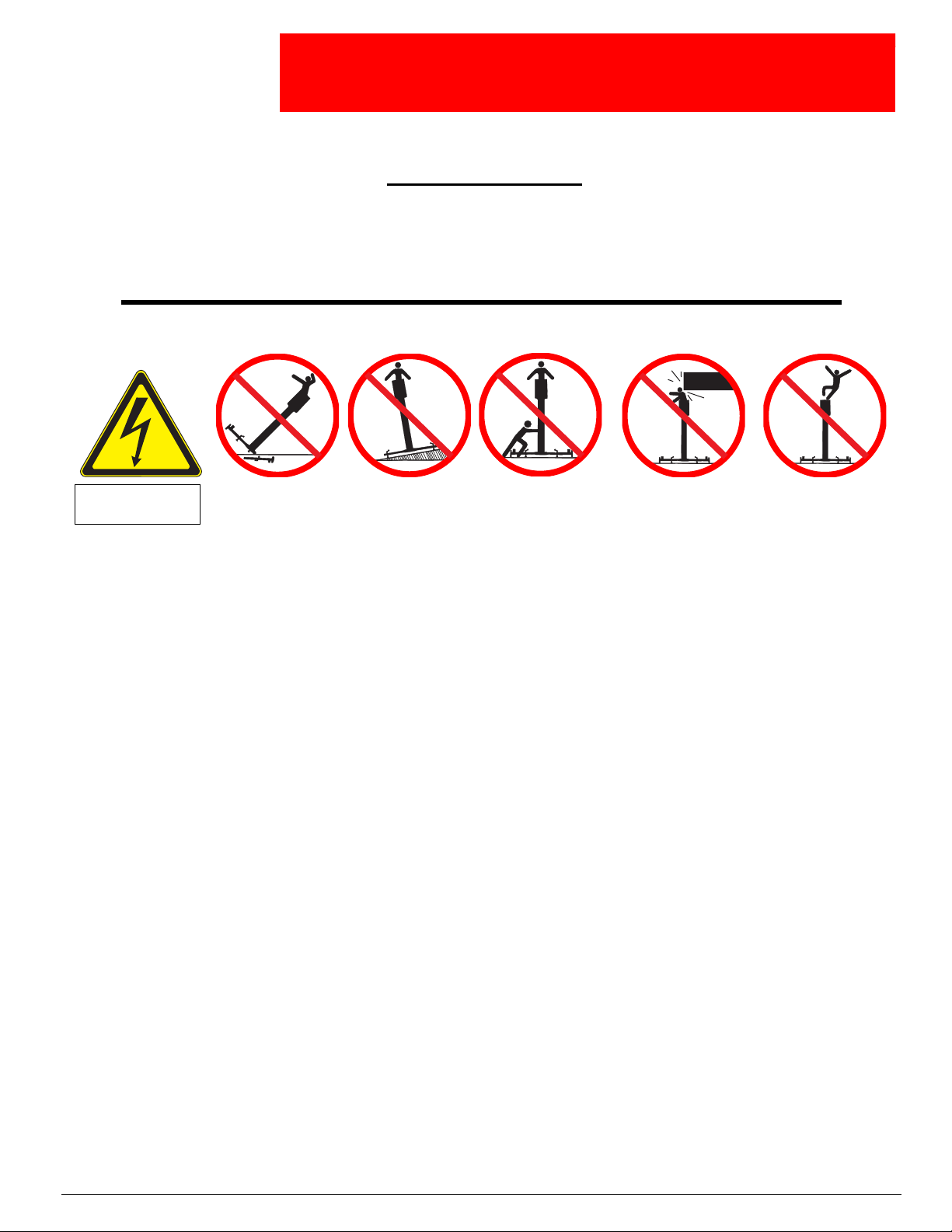
THIS MACHINE IS
NOT INSULATED!
THIS MACHINE IS FOR INDOOR USE ONLY! Do not use out of doors.
USE OF THE AERIAL WORK PLATFORM: This aerial work platform is intended to lift persons and his tools as well as the material
used for the job. It is designed for repair and assembly jobs and assignments at overhead workplaces (ceilings, cranes, roof structures,
buildings etc.). All other uses of the aerial work platform are prohibited!
THIS AERIAL WORK PLATFORM IS NOT INSULATED! For this reason it is imperative to keep a safe distance from live parts of electrical equipment!
Exceeding the specified permissible maximum load is prohibited! See “Special Limitations” on page 4 for details.
The use and operation of the aerial work platform as a lifting tool or a crane (lifting of loads from below upwards or from up high on
down) is prohibited!
NEVER exceed the manual force allowed for this machine. See “Special Limitations” on page 4 for details.
DISTRIBUTE all platform loads evenly on the platform.
NEVER operate the machine without first surveying the work area for surface hazards such as holes, drop-offs, bumps, curbs, or debris;
and avoiding them.
OPERATE machine only on surfaces capable of supporting wheel loads.
IN CASE OF EMERGENCY push EMERGENCY STOP switch to deactivate all powered functions.
Climbing up the railing of the platform, standing on or stepping from the platform onto buildings, steel or prefab concrete structures, etc.,
is prohibited!
Dismantling the entry gate or other railing components is prohibited! Always make certain that the entry gate is closed and securely
locked!
It is prohibited to keep the entry gate in an open position (held open with tie-straps) when the platform is raised!
To extend the height or the range by placing of ladders, scaffolds or similar devices on the platform is prohibited!
NEVER perform service on machine while platform is elevated without blocking elevating assembly.
INSPECT the machine thoroughly for cracked welds, loose or missing hardware, hydraulic leaks, loose wire connections, and damaged
cables or hoses before using.
VERIFY that all labels are in place and legible before using.
NEVER use a machine that is damaged, not functioning properly, or has damaged or missing labels.
To bypass any safety equipment is prohibited and presents a danger for the persons on the aerial work platform and in its working
range.
NEVER charge batteries near sparks or open flame. Charging batteries emit explosive hydrogen gas.
Modifications to the aerial work platform are prohibited or permissible only at the approval by UpRight.
AFTER USE, secure the work platform from unauthorized use by turning keyswitches off and removing key.
NEVER elevate the
platform unless all
four (4) outriggers
have been properly
installed.
NEVER elevate the
platform without first
leveling the base.
NEVER attempt to
push the UpRight Lift
withpeopleor
materials on the
platform or with the
platform elevated.
NEVER position the
platform without first
checkingfor overhead
obstructions or other
hazards.
NEVER climb, stand,
or sit on platform
guardrails or midrail.
Page 1
Page 4

068017-021 UL25, UL32 & UL40
C
ONTENTS
Introduction..........................................................................3
General Description ...................................................................3
SpecialLimitations....................................................................4
PlatformCapacity ........................................................................... 4
Manual Force . . ............................................................................ 4
ControlsandIndicators................................................................5
OutriggerInstallation..................................................................6
SafetyInterlockTest......................................................................... 6
Pre-OperationSafetyInspection.........................................................7
SystemFunctionInspection ............................................................7
Performalltestsfromtheground............................................................ 7
Operation............................................................................8
ElevatingthePlatform .................................................................... 8
LoweringthePlatform .................................................................... 8
EmergencyLowering..................................................................8
TransportingtheWorkPlatform.........................................................9
DC Models . ............................................................................ 9
Loading................................................................................... 9
Unloading ................................................................................ 10
DC Models . ........................................................................... 10
Passage Through a Doorway ..........................................................11
Lowering ................................................................................. 11
Raising .................................................................................. 11
Maintenance ........................................................................13
BatteryMaintenance........................................................................ 13
BatteryCharging........................................................................... 13
InspectionandMaintenanceSchedule...................................................14
Daily Preventative Maintenance Checklist................................................14
Labels .............................................................................16
Specifications.......................................................................18
Page 2 Operation Manual
Page 5
Introduction 068017-021 UL25, UL32 & UL40
I
NTRODUCTION
This manual covers operation of the UL25, UL32, and UL40 Work Platforms. This manual must be
stored on the machine at all times.
G
ENERAL
D
ESCRIPTION
!
WARNING
DO NOT use the maintenance platform without guardrails properly assembled and in place
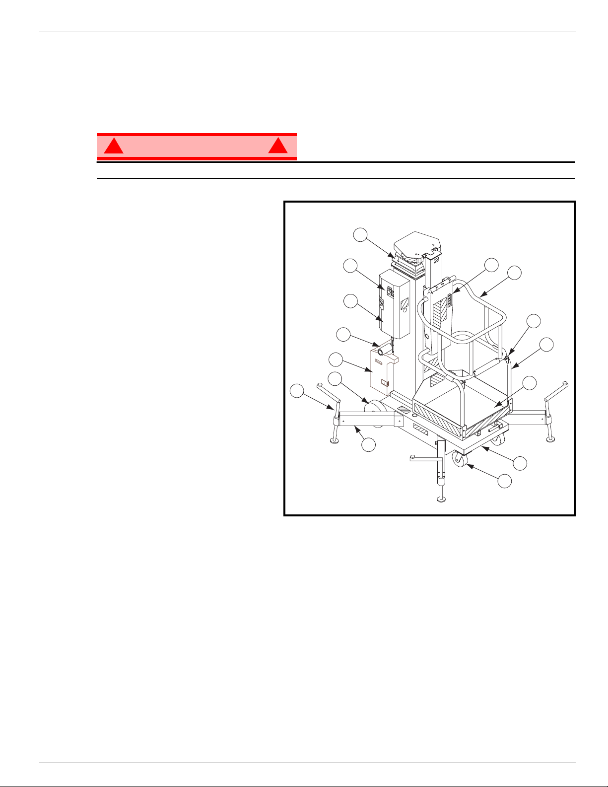
1. Platform
2. Mast
3. Chassis
4. Outriggers
5. Upper Guardrail (Gate)
6. Lower Guardrail
7. Chassis Controls
8. Power Unit
• Motor
• Hydraulic Reservoir
9. Battery Box(DC Units)
•Battery
• Battery Charger
10. Casters
!
Figure 1:
2
7
8
13
9
11
12
8
Work Platform
5
14
6
1
11. Rear Wheels
12. Screw Jacks
13. Loader Assembly
14. Gate Latch Pin
4
3
10
Operation Manual Page 3
Page 6

068017-021 UL25, UL32 & UL40 Special Limitations
S
PECIAL
L
IMITATIONS
Elevating the Work Platform is limited to firm, level surfaces only.
All four (4) outriggers must be properly installed before operating the machine.
This machine is rated for indoor use only.
DANGER
! !
The elevating function shall ONLY be used when the work platform is level and on a firm surface.
P
LATFORM
The maximum platform capacity for the MACHINE is:
• UL25- 159kg(350lbs).
• UL 32 and UL 40 - 136 kg (300 lbs).
One person may occupy the platform .
DANGER
! !
C
APACITY
DO NOT exceed the maximum platform capacity or the platform occupancy limits for this machine.
M
ANUAL
Manual force is the force applied by the occupants to objects such as walls or other structures outside the
work platform.
The maximum allowable manual force is limited to 200 N (45 lbs.) of force.
DANGER
! !
DO NOT exceed the maximum amount of manual force for this machine.
F
ORCE
Page 4 Operation Manual
Page 7
Controls and Indicators 068017-021 UL25, UL32 & UL40
C
ONTROLS AND
I
NDICATORS
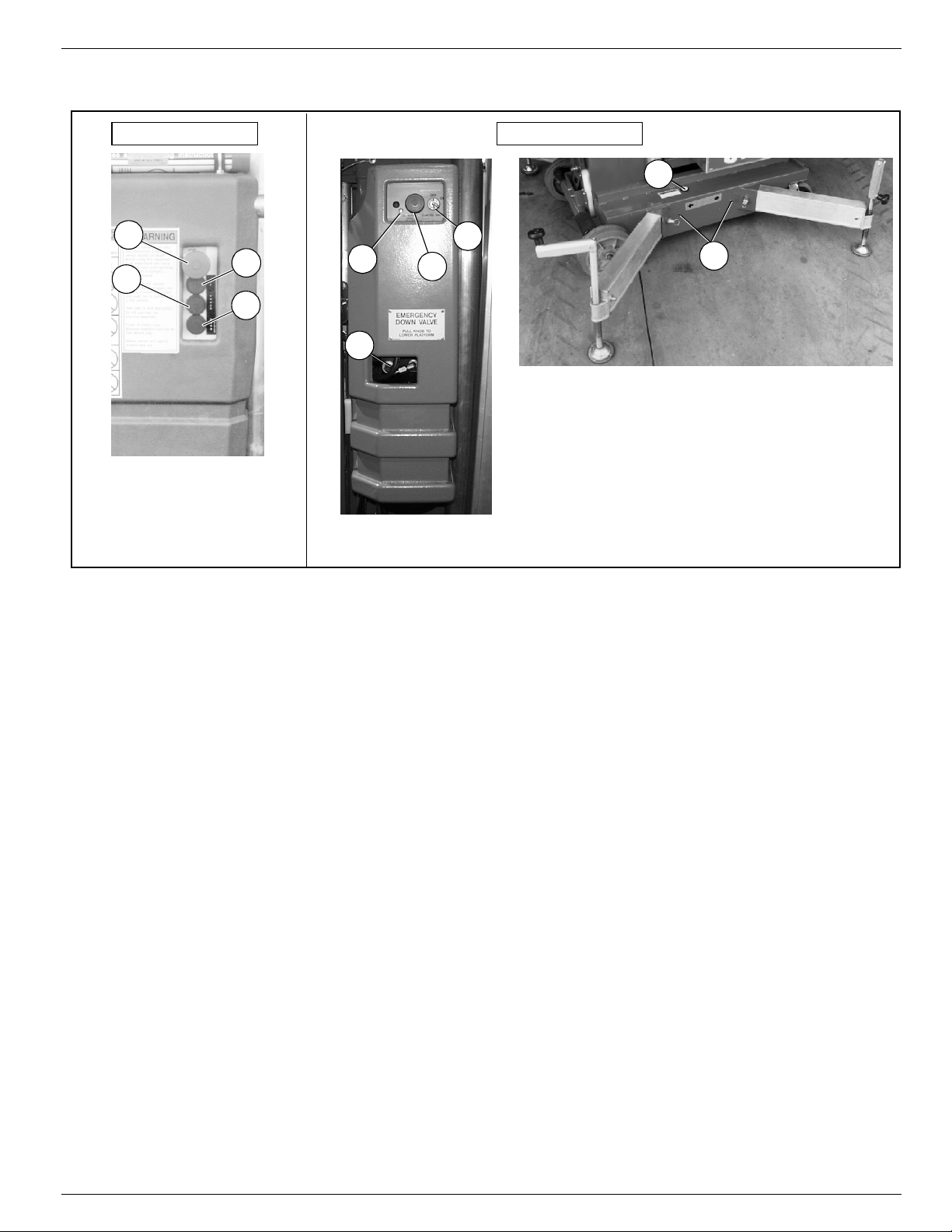
Platform Controls Chassis Controls
1
3
1
2
3
2
4
4
1 Emergency Stop Switch
2. Power On Button
3. Up Button
4. Down Button
5. Battery Charger
5
1 LED ( Indicates that
optional Emergency
Down from theplatform
battery needs replacing).
2. Emergency Stop
Switch
3. Key Switch
Figure 2:
Controls and Indicators
6
4. Emergency Lowering
Valve
5. Orbit Level
6. Outrigger Indicator
Lights
Operation Manual Page 5
Page 8
068017-021 UL25, UL32 & UL40 Outrigger Installation
O
UTRIGGER
I
NSTALLATION
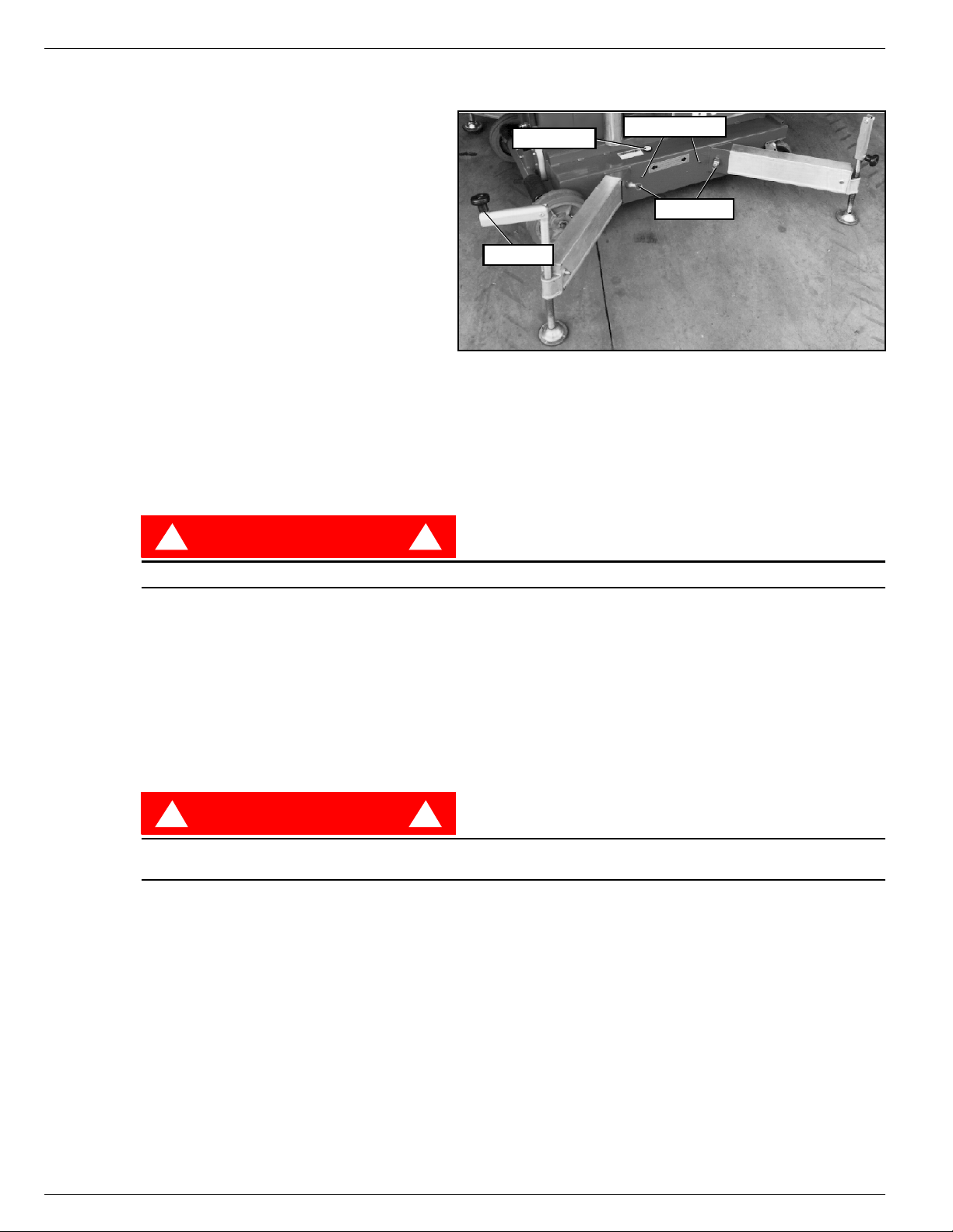
Figure 3:
1. Remove the outriggers from storage
locations on the sides of the mast.
2. Insert into the outrigger socket in the
base (Figure 1).
3. Push in until the locking pin engages
the hole in the end of the outrigger. Pull
outward on the outrigger to ensure
engagement.
4. Repeat the above steps for all other
outriggers. Make sure all four (4) locking pins are engaged.
5. Level the base, centering the bubble in
the orbit level on the base by adjusting the screwjacks (turn clockwise) at the end of each outrigger. DO
NOT release the tension (turn counterclockwise) on an outrigger to level the base.
6. All four (4) screwjack pads must be in solid contact with a firm surface and each outrigger indicator light
must be lit before the platform is elevated.
S
AFETYINTERLOCK
DANGER
! !
T
EST
Bubble Level
Screwjack
Indicator Lights
Locking Pin
Installing Outriggers
NEVER perform this test from the platform.
1. Properly install all four (4) outriggers and level the base.
2. Release the tension on one (1) outrigger by turning the screwjack counter clockwise until the indicator
light is no longer lit.
3. While standing on the ground, activate the control panel to elevate the platform. The platform should
not elevate.
4. Re-level the base.
5. Repeat steps 2, 3 and 4 until all four (4) outriggers have been tested.
DANGER
! !
DO NOT use a machine that elevates when the tension has been released on an outrigger. The
machine must be repaired before using.
Page 6 Operation Manual
Page 9
Pre-Operation Safety Inspection 068017-021 UL25, UL32 & UL40
P
RE
-O
PERATION
S
AFETYINSPECTION
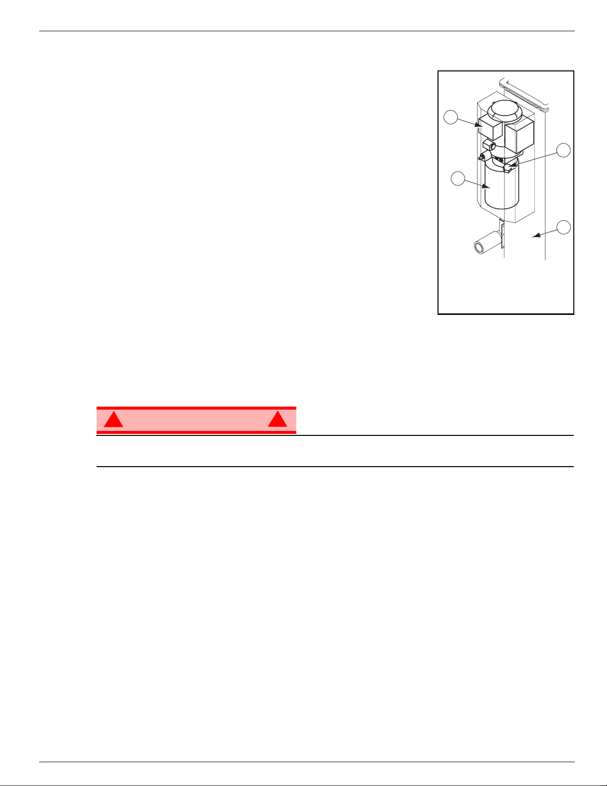
Figure 4:
NOTE: Carefully read, understand and follow all safety rules, operating
instructions, labels andNational Safety Instructions/Requirements.Perform the
following steps each day before use.
1. Check that all four (4) outriggers are properly installed.
2. Check that the base is level.
3. AC Units: connect the power unit plug to an approved extension cord.
4. DC Units: Verify that batteries are charged.
5. Perform the Safety Interlock test.
6. Check for external damage to the mast.
7. Check the level of the hydraulic fluid with the platform fully lowered:
• Remove the reservoir cap and check the fluid level on the dipstick.
• Add hydraulic fluid if necessary.
8. Check that fluid level in the batteries is correct. See “Battery Maintenance” on page 13.
9. Check that all guardrails are in place and all fasteners are properly
tightened.
10. Inspect the machine thoroughly for cracked welds and structural damage, loose or missing hardware, hydraulic leaks, damaged control cable, and loose wire connections.
3
1
1 Hydraulic Reservoir
2. Reservoir Cap/Dipstick
3. Motor (AC Shown)
4. Mast
Hydraulic Reservoir
2
4
S
YSTEM
F
UNCTION
Refer to Figure 2: “Controls and Indicators,” on page 5 for the locations of various controls and indicators.
!
WARNING
STAND CLEAR of the work platform while performing the following checks.
Check above the work platform for obstructions and electrical conductors.
NOTE: The platform will not elevate unless all four outriggers are properly installed with screwjack pads firmly in
contact with floor and each outrigger indicator lamp lit.
P
ERFORM ALL TESTS FROM THE GROUND
1. Pull the Chassis Emergency Stop Switch to the ON position.
2. Turn the Key to ON.
3. Pull the Platform Emergency Stop Switch to the ON position.
4. Push both the middle and top buttons (POWER and UP) on the Control Box at the same time to elevate
the platform. Release the buttons to stop.
5. Push both the middle and bottom buttons (POWER and DOWN) at the same time to lower the platform.
Release the buttons to stop.
6. Open the Emergency Lowering Valve to verify proper operation.
7. Push the Chassis Emergency Stop Switch to verify proper operation. All machine functions should be
disabled. Pull out the Chassis Emergency Stop Switch to resume.
8. Push the Platform Emergency Stop Switch to verify proper operation. All machine functions should be
disabled. Pull out the Platform Emergency Stop Switch to resume.
I
NSPECTION
!
Operation Manual Page 7
Page 10

068017-021 UL25, UL32 & UL40 Operation
O
PERATION
Before operating the machine, ensure that the Pre-Operation Safety Inspection has been completed and
that any deficiencies have been corrected. Never operate a damaged or malfunctioning machine. The
operator must be thoroughly trained on this machine.
NOTE: The platform will not elevate unless all four outriggers are properly installed with screwjack pads firmly in
contact with floor and each outrigger indicator lamp lit.
1. AC Units: connect the power unit plug to an approved extension cord.
2. DC Units: verify that the battery charger is turned OFF and that the extension cord is removed.
3. Pull the Chassis Emergency Stop Switch to the ON position.
4. Turn the Key to ON.
5. Enter the platform by pulling out on the locking pin and lifting up on the upper half of the cage.
6. Lower upper half of the cage after entering platform making sure locking pin is engaged.
E
LEVATING THEPLATFORM
7. Check that the area above the platform is clear before elevating the platform.
8. Pull the Platform Emergency Stop Switch to the ON position.
9. Push both the middle and top buttons (POWER and UP) on the Control Box at the same time to elevate
the platform. Release the buttons to stop.
• In the event of an emergency, push the Emergency Stop Button.
10. Visually inspect the mast assembly for cracked welds and structural damage, loose hardware, hydraulic
leaks, loose wire connections, and erratic operation. Check for missing or loose parts.
L
11. Check that the area below the platform is clear before lowering the platform.
12. Push both the middle and bottom buttons (POWER and DOWN) at the same time to lower the platform.
E
MERGENCY
NOTE: The platform will not elevate if the Emergency Lowering Valve is open.
OWERING THEPLATFORM
Release the buttons to stop.
L
OWERING
Refer to Figure 2: “Controls and Indicators,” on page 5 for the location of the Emergency Lowering Valve.
!
WARNING
If the platform should fail to lower, NEVER climb down the elevating assembly.
Stand clear of the elevating assembly while operating the Emergency Lowering Valve Knob.
Ask a person on the ground to open the Emergency Lowering Valve to lower the platform. This valve is
located through a cutout in the power unit cover on the left side of the mast.
1. Pull the knob to open the valve.
2. To close the valve, release the knob.
!
Page 8 Operation Manual
Page 11
Transporting the Work Platform 068017-021 UL25, UL32 & UL40
T
RANSPORTING THE
W
ORK
P
LATFORM
DC M
L
ODELS
Disconnect the plug from the battery box and remove the battery box from the rear of the machine.
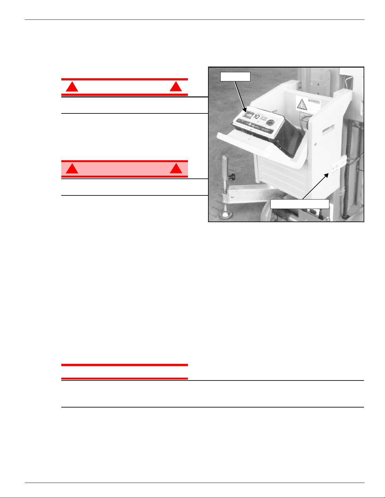
Battery Box (DC Models Only)
!
CAUTION
The battery box is heavy, 23,6 kg (52 lbs.). Lift
properly to prevent back injury.
!
Figure 5:
Charger
OADING
Refer to Figure 6: “Loading the UL for Transportation,” on page 10.
!
WARNING
Make sure the loader fully engages the tailgate or
vehicle bed.
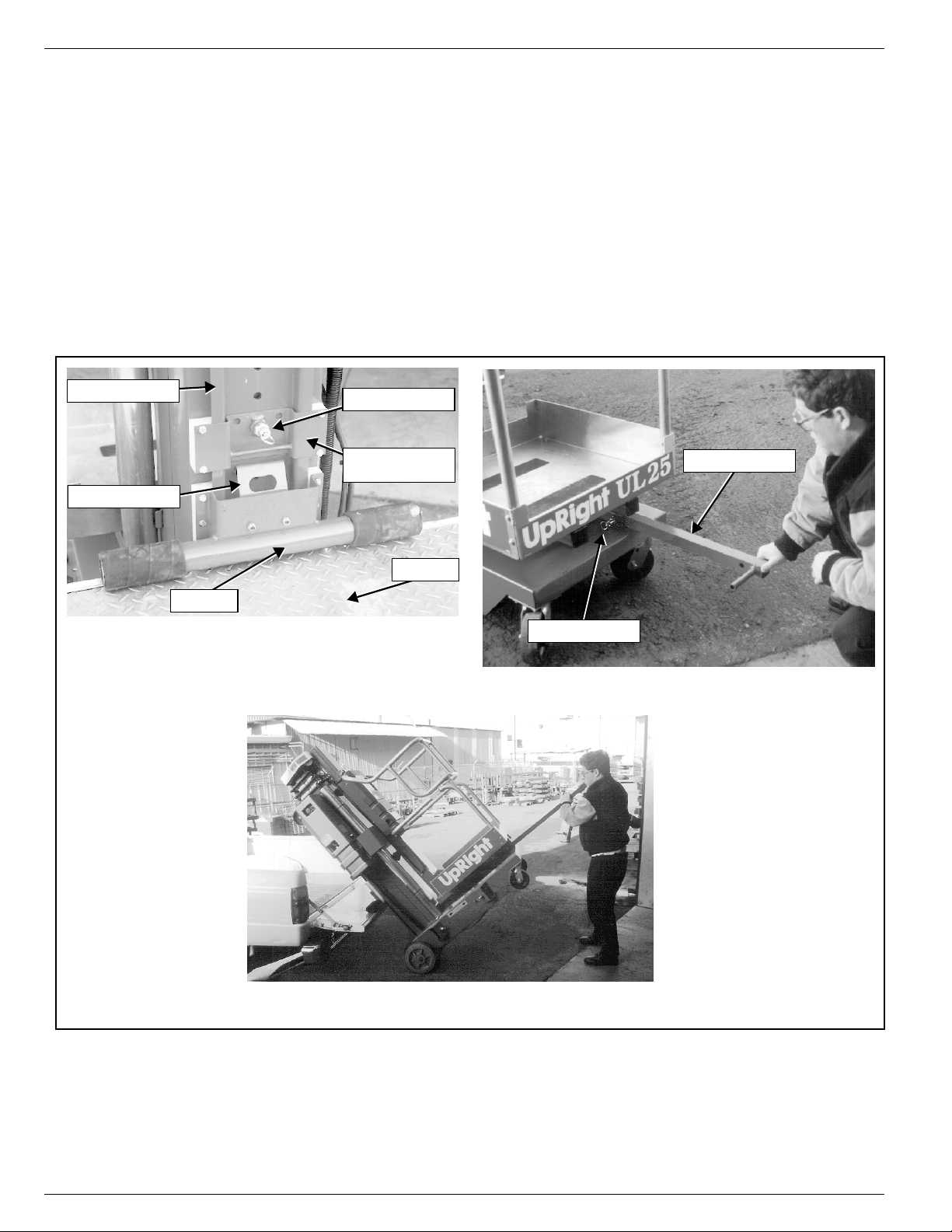
1. Raise the loader support brackets and engage
the retaining pin in the top hole of the loader
channel.
2. Secure the loader to the loader support bracket with the gravity hook.
3. Position the unit so the back of the machine comes into contact with the tailgate or vehicle bed.
4. Release the gravity hook and slide the loader down until it comes into contact with the tailgate or vehicle
bed. Then reposition the loader support bracket so that the retaining pin is in the first available hole
above the loader.
5. Release the locking pin and pull the T-handle out until the locking pin engages the hole in the end of the
T-handle.
6. Lift up on the T-handle, using the loader as a pivot, until the unit rotates to a horizontal position in the
vehicle bed.
7. Push the base of the unit towards the front of the vehicle bed. The machine will slide on the loader until
the rear wheels are on the bed. The unit may then be rolled on the rear wheels and upper casters.
8. Return the T-handle to the stored position, making sure that the locking pin engages the T-handle.
9. Secure the unit with suitable tie straps using the forklift pockets located under the base of the unit, and
either the upper caster axle on the UL25 models or the tilt back frame on the UL32 and UL40 models.
!
Battery Box Plug
CAUTION
To prevent damage to the mast assembly, do not place rope or tie straps across the mast assembly when
securing the unit for transportation.
DO NOT overtighten the rope or tie straps or damage to the machine will result.
Operation Manual Page 9
Page 12
068017-021 UL25, UL32 & UL40 Transporting the Work Platform
U
NLOADING
1. Unsecure the unit.
2. Release the locking pin and pull the T-handle out until the locking pin engages the hole in the end of the
T-handle.
3. Roll the unit back until the rear wheels are off the edge of the tailgate or vehicle bed.
4. Pull downward on the T-handle, allowing the unit to slide on the loader.
• As the unit stops sliding on the loader, it will pivot on the loader to an upright position.
• Gradually counterbalance the unit’s weight by applying an upward force on the T-handle. This allows
the unit to settle gently on the wheels, avoiding undue impact on the unit.
5. Return the T-handle to the stored position, making sure that the locking pin engages the T-handle.
DC M
Loader Channel
Gravity Hook
ODELS
Replace the battery and reconnect the battery box plug, making certain it is fully engaged.
Loading the UL for Transportation
Retaining Pin
Loader
Loader in Load Position
Retaining Pin
Loader Support
Bracket
Tailgate
Figure 6:
Retaining Pin
T-Handle Positioning
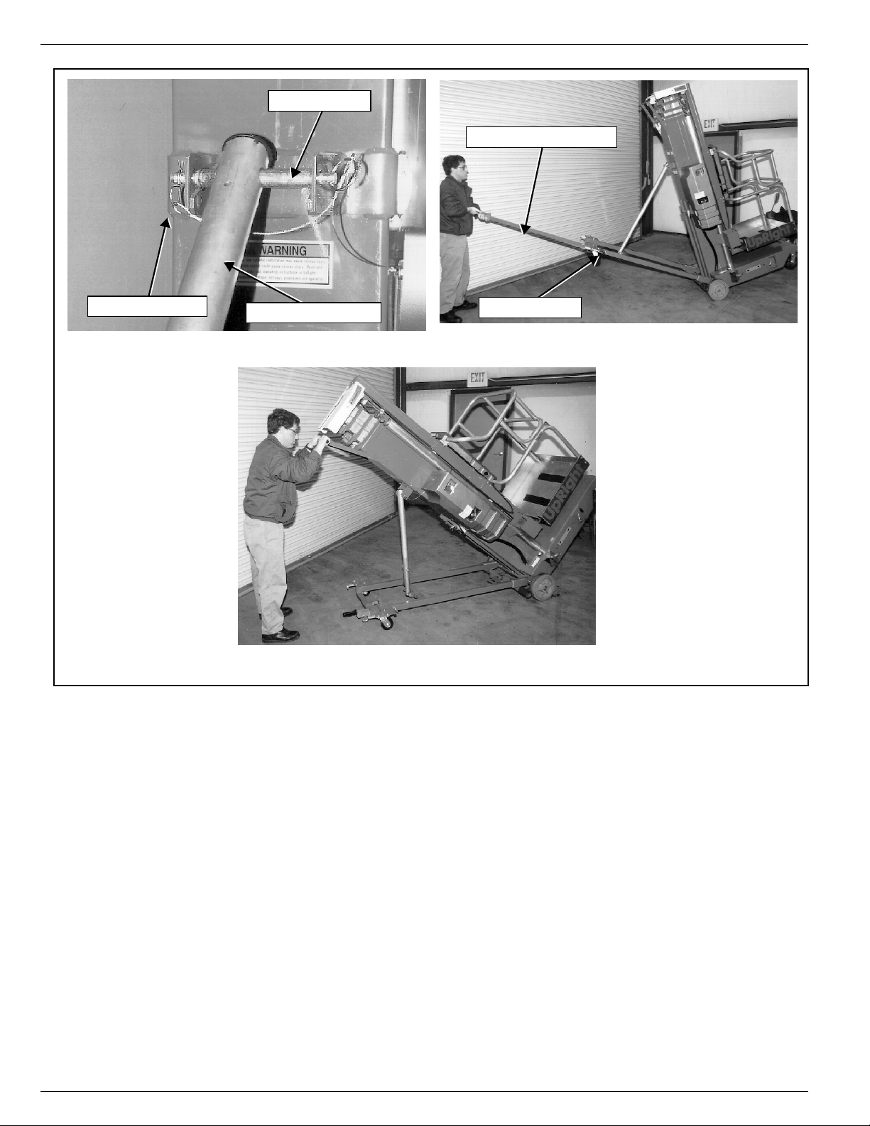
Tilting the Machine Onto or Off of a Vehicle
Page 10 Operation Manual
Page 13

Passage Through a Doorway 068017-021 UL25, UL32 & UL40
P
ASSAGE
L
T
HROUGH A
The UL32 and UL40 are equipped with a castered rear Tilt Back assembly. When the unit is tilted back
onto this support frame, the overall height is reduced to allow the unit to pass through a standard doorway.
Refer to Figure 7: “Passing Through Doorways,” on page 12.
D
OORWAY
OWERING
!
CAUTION
Before tilting the machine onto the rear Tilt Back assembly, be sure that the retaining pin is fully inserted
with the hair pin retainer installed and the cylinder assembly is fully extended.
DO NOT drop the Tilt Back frame.
Keep out from under the Tilt Back frame and machine when tilting.
1. Be sure that the area is clear of personnel and obstructions.
2. While holding the Tilt Back frame, remove the hair pin retainer and the retaining pin.
3. Lower the Tilt Back frame until the hole in the cylinder assembly align with the upper mounting bracket
pin hole. Secure the cylinder assembly to the upper mounting bracket using the retaining pin and hair pin
retainer.
4. Extend the Tilt Back Handle to the tilt/lift position by releasing the locking pin and pulling the handle out
of the Tilt Back assembly until the locking pin engages.
5. Push down on the Tilt Back Handle until the unit comes to rest on the Tilt Back frame.
• As the mast tilts back, counterbalance the machine’s weight by increasing upward force on the end of
the Tilt Back Handle. This allows the machine to gently come to rest on the Tilt Back casters.
6. Pull down on the handle on the back of the mast to compress the cylinder assembly.
7. Return the Tilt Back Handle to the storage position, making sure that the locking pin engages the handle.
R
AISING
1. Lift up on the mast handle to extend the cylinder assembly.
2. Fully engage the Tilt Back Handle until the locking pin engages.
3. Lift up on the Tilt Back Handle.
• As the mast approaches vertical, counterbalance the machine’s weight by increasing downward force
on the end of the tilt Back Handle. This allows the machine to settle gently on the front casters.
4. Return the Tilt Back handle to the storage position, making sure that the locking pin engages the handle.
5. While holding the Tilt Back frame, remove the retaining pin and raise the Tilt Back assembly to the
stowed position.
6. Secure with the retaining pin, making sure that the retaining pin is fully inserted, and that the hair pin
retainer is installed.
!
Operation Manual Page 11
Page 14
068017-021 UL25, UL32 & UL40 Passage Through a Doorway
Hair Pin Retainer
Cylinder Secured with Retaining Pin
Retaining Pin
Cylinder Assembly
Figure 7:
Tilt Back Handle
Retaining Pin
Lowering and Raising with the Tilt Back Handle
Passing Through Doorways
Compressing the Cylinder Assembly
Page 12 Operation Manual
Page 15
Maintenance 068017-021 UL25, UL32 & UL40
M
AINTENANCE
B
ATTERY
M
AINTENANCE
!
WARNING
Hazard of explosive gas mixture. Keep sparks, flame, and smoking material away from batteries.
Always wear safety glasses when working near batteries.
Battery fluid is highly corrosive. Thoroughly rinse away any spilled fluid with clean water.
Always replace batteries with UpRight batteries or manufacturer approved replacements weighing
22 kg (48 lbs.) each.
• Check the battery fluid level daily, especially if the work platform is being used in a warm, dry climate.
• If electrolyte level is lower than 10 mm (
tap water with high mineral content, as it will shorten battery life.
• Keep the terminals and tops of the batteries clean.
• Refer to the Service Manual to extend battery life and for complete service instructions.
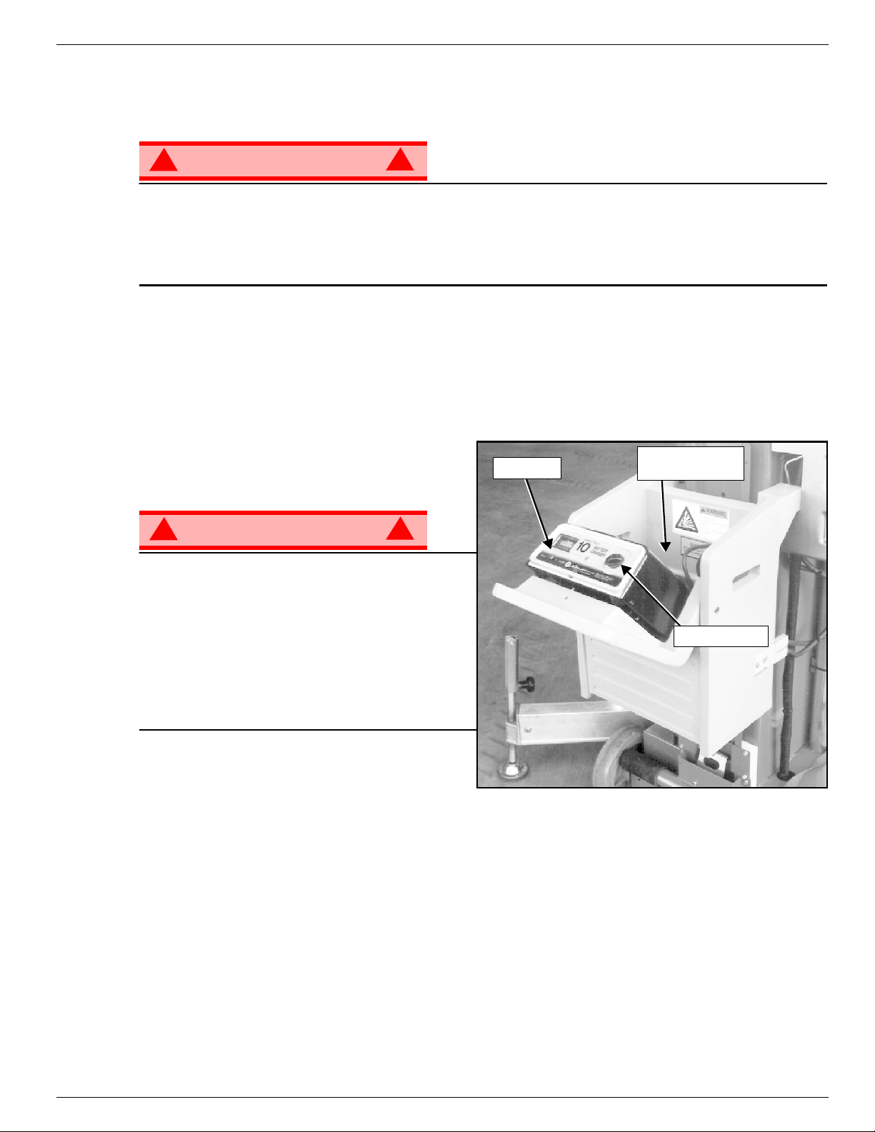
B
ATTERY
Charge the batteries at the end of each work shift
or sooner if the batteries have been discharged.
!
WARNING
Charge the batteries in a well ventilated area.
Do not charge the batteries when the work
platform is near a source of sparks or flames.
Permanent damage to the batteries will result if
the batteries are not immediately recharged after
discharging.
Never disconnect the cables from the batteries
when the charger is operating.
Keep the charger dry.
C
HARGING
!
3
in.) above the plates add distilled water only. DO NOT use
/
8
Battery Charger
Charger
Figure 8:
Battery
(inside box)
!
Timer Knob
1. Check the battery fluid level. If the battery fluid
level is lower than 10 mm (
plates add distilled water only.
2. Verify the charger voltage switch is set to 12 volts.
3. Connect an appropriate extension cord to the charger plug. Plug the extension cord into a properly
grounded outlet of proper voltage and frequency.
4. Turn the charger timer knob to 12. The charger ammeter should indicate the charge rate.
5. When the battery is fully charged, turn the knob to OFF, do not turn the knob to HOLD. Disconnect the
extension cord.
NOTE: The battery charger circuit must be used with a GFI (Ground Fault Interrupt) outlet.
NOTE: DO NOT operate the machine while the charger is plugged in.
Operation Manual Page 13
3
in.) above the
/
8
Page 16
068017-021 UL25, UL32 & UL40 Inspection and Maintenance Schedule
I
NSPECTION AND
The Complete Inspection consists of periodic visual and operational checks, along with periodic minor
adjustments that assure proper performance. Daily inspection will prevent abnormal wear and prolong the
life of all systems. The inspection and maintenance schedule should be performed at the specified intervals. Inspection and maintenance shall be performed by personnel who are trained and familiar with
mechanical and electrical procedures.
M
AINTENANCE
S
CHEDULE
D
AILY
M
AINTENANCE
Y = Yes/Acceptable
N = No/Not Acceptable
R = Repaired/Acceptable
!
WARNING
!
Before performing preventative maintenance, familiarize yourself with the operation of the machine.
Always block the elevating assembly whenever it is necessary to perform maintenance while the
platform is elevated.
The daily preventative maintenance checklist has been designed for machine service and maintenance.
Please photocopy the Daily Preventative Maintenance Checklist and use the checklist when inspecting
the machine.
P
REVENTATIVE
T
ABLEKEY
M
AINTENANCE
C
HECKLIST
P
REVENTATIVE
Date: _______________________________________
Owner:______________________________________
Model No: ___________________________________
Serial No:____________________________________
Serviced By: _________________________________
M
AINTENANCEREPORT
COMPONENT INSPECTION OR SERVICES Y N R
Battery
Chassis
Control Cable
Controller Check switch operation.
Mast Assembly Inspect for bends, cracks or loose rivets.
Check electrolyte level.
Check battery cable condition.
Check bubble level accuracy
Check operation of outrigger interlocks
Check casters for damage
Check hoses for pinch or rubbing points.
Check welds for cracks.
Check theexterior of the cable for pinching, binding
or wear.
COMPONEN T INSPECTION OR SERVICES Y N R
Emergency
Lowering System
Hydraulic Fluid Check fluid level.
Hydraulic Pump Check for hose fitting leaks.
Hydraulic System Check for leaks.
Labels
Cage and Deck
Operatethe emergency lowering valve andcheckfor
serviceability.
Check for peeling, missing, or unreadable labels &
replace.
Check welds for cracks.
Check condition of deck.
Page 14 Operation Manual
Page 17

Daily Preventative Maintenance Checklist 068017-021 UL25, UL32 & UL40
OTES
N
:
Operation Manual Page 15
Page 18
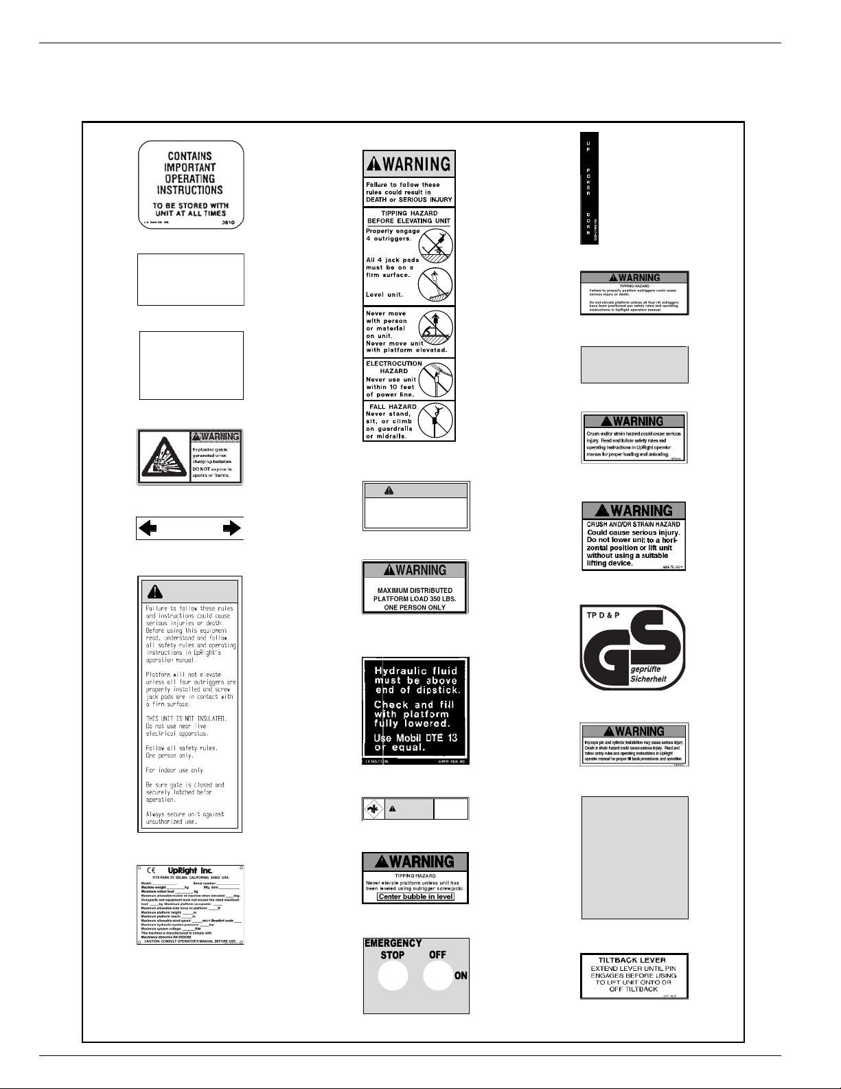
068017-021 UL25, UL32 & UL40 Labels
L
ABELS
These labels shall be present and in good condition before operating the work platform. Be sure to read,
understand and follow these labels when operating the work platform.
1) 003610-000
23) 062840-000
BATTERY
MAINTAIN BATTERY FLUID
AT RECOMMENDED LEVEL
4) 005221-000 - UL40 DC ONLY
EMERGENCY
DOWNVALVE
PULL KNOB TO
LOWER PLATFORM
5) 005223-003
25) 062821-002
EMERGENCY
STOP
26) 062792-000
6) 066552-000 - UL40 DC ONLY
Insert outrigger here
until pin engages hole.
10) 062218-001
WARNING
11) 066554-003
15) 066550-010
WARNING
MAXIMUM PLATFORM
LOAD 300 LBS.
ONE PERSON ONLY.
16) 066557-009 - UL32 & 40 ONLY
16) 066557-011 - UL25 ONLY
17) 062217-000
PINCH POINT
WARNING
Keep all body
parts away.
18) 066553-002
27) 062725-002
28) 062575-001
34) 030768-002
35) 062466-002
INSERT
PIN
HERE
19) 066551-005
36) 062814-000
14) 061205-003
37) 062876-000
20) 069338-000
Page 16 Operation Manual
Page 19

Labels 068017-021 UL25, UL32 & UL40
Figure 9:
35
Safety Labels Locations
Operation Manual Page 17
Page 20

068017-021 UL25, UL32 & UL40 Specifications
S
PECIFICATIONS
ITEM UL 25 UL 32 UL 40
Platform Capacity 159 kg (350 lbs.)136kg(300 lbs.)136kg(300 lbs.)
Max. No. of occupants 1 person 1 person 1 person
Height
Working Height 9,62 m (31.6 ft.)11,75m(38.5 ft.) 14,19 m (46.6 ft.)
Max. Platform Height
Min. Platform Height 38 cm (15 in.)38cm(15 in.)38cm(15 in.)
Dimensions
Overall Weight 345 kg (760 lbs.)390kg(860 lbs.)422kg(930 lbs.)
DC Option Weight
Overall Width (outriggers extended) 1,5 m (59 in.)2,06m(81 in.)2,34m(92 in.)
Overall Length (outriggers extended) 1,42 m (56 in.)1,98m(78 in.)2,26m(89 in.)
Stowed Dimensions
Vertical Height
Width 74 cm (29 in.)74cm(29 in.)74cm(29 in.)
Depth
Diagonal Storage Height
Diagonal Storage Length N/A 2,53 m (99.5in.)2,9m(114 in.)
System Voltage
AC Electric Motor
DC Electric Power Source 1 - 12 Volt Battery, Group 27 105 Amp/Hrs., Minimum Weight 22 kg (48 lbs.)
Battery Charger
Hydraulic Tank Capacity 5,7 liter (1.5 gal.)
Maximum Hydraulic Pressure 165 bar(2400 PSI)
Hydraulic Fluid
Normal Temperature: above 0° C [32° F]
Low Temperature: below 0° C [32° F]
ExtremeTemperature: below-17° C [0° F]
Control System Push Button Lift and Lower, Red Mushroom EMERGENCY STOP Switch
Guardrails 1,1 m (43.5 in.)High
Noise Level
7,62 m (25 ft.)9,75m(32 ft.)12,19m(40 ft.)
29 kg (64 lbs.)29kg(64 lbs.)29kg(64 lbs.)
1,98 m (78 in.)2,44m(96 in.)2,84m(112 in.)
1,24 m (49 in.)1,24m(49 in.)1,24m(49 in.)
N/A 1,98 m (78 in.)1,98m(78 in.)
120 VAC 60 Hz or 220 VAC 50/60 Hz
Automatic, 120 VAC 60 Hz or 220 VAC 50 Hz
Output: 10 Amp, 12 Volts DC
ISO #46
ISO #32
ISO #15
*Specifications are subject to change without notice. Hot weather or heavy use may affect performance.
Refer to the Service Manual for complete parts and service information.
The UL25/32/40 meets or exceeds all applicable CE and GS machinery directive requirements.
Page 18 Operation Manual
Page 21

Tout le personnel doit lire attentivement et respecter toutes les consignes de sécurité avant
Risque
Risque
RisqueRisque
d’électrocution
d’électrocution
d’électrocutiond’électrocution
GUIDE DE L’OPÉRATEUR
AVERTISSEMENT
d’entretenir ou d’utiliser une plate-forme élévatrice UpRight.
Consignes de sécurité
Consignes de sécurité
Consignes de sécuritéConsignes de sécurité
Risque de collision
Risque de collision
Risque de basculement
Risque de basculement
Risque de basculementRisque de basculement
Risque de collisionRisque de collision
Risque de chute
Risque de chute
Risque de chuteRisque de chute
CETTE MACHINE
N’EST PAS ISOLÉE !
CETTE MACHINE EST CONÇUE POUR N’ÊTRE UTILISÉE QU’À L’INTÉRIEUR ! Ne pas l’utiliser à l’extérieur.
USAGEDELAPLATE-FORMEÉLÉVATRICE: Cette plate-forme élévatrice est destinée au levage de toute personne, de son outillage
et des matériaux utilisés sur le chantier. Elle est conçue pour les travaux de réparations et d’assemblage sur les points élevés (plafonds,
grues, charpentes de toit, immeubles, etc.). Tout autre usage de la plate-forme élévatrice est interdit !
CETTE PLATE-FORME ÉLÉVATRICE N’EST PAS ISOLÉE ! C’est pourquoi il est impératif de rester à distance sûre des lignes et
équipements électriques sous tension !
Il est interdit de dépasser la charge maximum admissible. Voir « Limitations particulières » à la page 22 pour plus de détails.
Il est interdit d’utiliser la plate-forme comme appareil de levage ou grue (levage des charges par le dessous ou le dessus) !
NE JAMAIS dépasser la force manuelle autorisée pour cette machine. Voir « Limitations particulières » à la page 22 pour plus de
détails.
RÉPARTIR uniformément toutes les charges placées sur la plate-forme.
NE JAMAIS utiliser la machine sans avoir d’abord vérifié si la zone de travail est exempte de dangers tels que des trous, dénivellations,
bosses, trottoirs ou débris; et les éviter.
N’UTILISER la machine que sur des surfaces pouvant supporter la charge des roues.
EN CAS D’URGENCE, appuyer sur le bouton d’ARRÊT D’URGENCE pour désactiver toutes les fonctions.
Il est interdit de monter ou de se tenir sur les garde-corps de la plate-forme et de passer de la plate-forme à un immeuble, une
structure préfabriquée, etc. !
Il est interdit de retirer le portillon ou toute autre pièce de garde-corps ! Toujours vérifier que le portillon est fermé et verrouillé !
Il est interdit de maintenir le portillon en position ouverte (par exemple au moyen d’attaches) lorsque la plate-forme est élevée !
Il est interdit d’accroître la hauteur ou la portée de la plate-forme au moyen d’échelles, échafaudages ou autres dispositifs similaires !
NE JAMAIS effectuer de travaux d’entretien sur la machine, si la plate-forme est en position élevée, sans tout d’abord bloquer le
système d’élévation.
INSPECTER minutieusement la machine en vue de soudures fissurées, de pièces de boulonnerie manquantes ou desserrées, de fuites
hydrauliques, de branchements électriques desserrés ou de câbles et flexibles endommagés avant d’utiliser la machine.
VÉRIFIER que tous les autocollants sont en place et lisibles avant d’utiliser la machine.
NE JAMAIS utiliser une machine qui est endommagée, qui ne fonctionne pas correctement ou dont les autocollants sont manquants ou
endommagés.
Il est interdit de mettre tout dispositif de sécurité hors service, ce qui mettrait en danger les personnes à bord de la plate-forme et
celles se trouvant dans la zone de travail.
NE JAMAIS charger les batteries à proximité d’étincelles ou d’une flamme vive. Lors de la charge, les batteries dégagent de
l’hydrogène, un gaz explosif.
Sauf autorisation de la part d’UpRight, toute modification de la plate-forme est interdite.
APRÈS AVOIR UTILISÉ la plate-forme élévatrice, mettre les contacteurs à clé en position d’arrêt (OFF), puis retirer la clé afin
d’empêcher l’utilisation non autorisée de la plate-forme.
NE JAMAIS
élever la plate-forme
si les quatre (4)
stabilisateurs (4) ne
sont pas correctement
installés.
NE JAMAIS
élever la plate-forme
avant d’avoir mis la
base de niveau.
NE JAMAIS
essayer de pousser la
plate-forme UpRight
si elle est occupée
par despersonnes ou
du matériel ou
si elle est élevée.
NE JAMAIS
positionner la plate-
forme avant de s’être
assuré de l’absence
d’obstacles
en hauteur
ou autres dangers.
NE JAMAIS
monter, ni se tenir
debout ou assis sur
les rampes
du garde-corps.
Page 19
Page 22

068017-021 UL25, UL32 et UL40
T
ABLE DES MATIÈRES
Introduction.........................................................................21
Descriptiongénérale .................................................................21
Limitationsparticulières ..............................................................22
Capacitédelaplate-forme ................................................................... 22
Forcemanuelle............................................................................ 22
Commandesetindicateurs............................................................23
Installationdesstabilisateurs..........................................................24
Test de verrouillage de sécurité . .............................................................. 24
Inspection de sécurité avant utilisation ..................................................25
Essaidefonctionnementdessystèmes..................................................25
Effectuertoustestsàpartirdusol.......................................................... 25
Utilisation ..........................................................................26
Élévationdelaplate-forme ............................................................... 26
Abaissementdelaplate-forme ............................................................ 26
Abaissement d’urgence ...............................................................26
Transport de la plate-forme élévatrice . ..................................................27
Modèles c.c............................................................................ 27
Chargement............................................................................... 27
Déchargement............................................................................. 28
Modèles c.c............................................................................ 28
Passagedeportes ...................................................................29
Abaissement.............................................................................. 29
Élévation................................................................................. 29
Entretien ...........................................................................31
Entretiendesbatteries ...................................................................... 31
Chargedesbatteries........................................................................ 31
Programmesd’inspectionetd’entretien.................................................32
Liste de contrôle d’entretien préventif quotidien ..........................................32
Autocollants ........................................................................34
Caractéristiques.....................................................................36
Page 20 Guidedel’opérateur
Page 23

Introduction 068017-021 UL25, UL32 et UL40
I
NTRODUCTION
Ce manuel contient les instructions d'utilisation de la plate-forme élévatrice UL25, UL32 et UL40.
Veiller à garder ce manuel sur la machine en tout temps.
D
ESCRIPTION GÉNÉRALE
!
AVERTISSEMENT
NE PAS utiliser la plate-forme sans que les garde-corps soient correctement assemblésetinstallés.
1. Plate-forme
2. Mât
3. Châssis
4. Stabilisateurs
5. Garde-corps supérieurs
(portillon)
6. Garde-corps inférieurs
7. Commandes du châssis
8. Bloc d’alimentation
• Moteur
• Réservoir hydraulique
9. Boîte à batteries (modèles c.c.)
•Batterie
• Chargeur de batterie
10. Roulettes
11. Roues arrière
12. Crics à vis
13. Chargeur
!
Figure 1 :
2
7
8
13
9
11
12
4
Plate-forme élévatrice
8
5
14
1
3
10
6
14. Axe de verrouillage de portillon
Guidedel’opérateur Page 21
Page 24

068017-021 UL25, UL32 et UL40 Limitations particulières
L
IMITATIONS PARTICULIÈRES
La plate-forme ne doit être élevée que si elle se trouve sur une surface plane et ferme.
Les quatre (4) stabilisateurs doivent être correctement installés avant d’utiliser la machine.
Cette machine est conçue pour n’être utilisée qu’à l’intérieur !
DANGER
! !
La fonction d’élévation doit être utilisée SEULEMENT lorsque la plate-forme est de niveau et placée
sur une surface plane et ferme.
C
APACITÉ DE LA PLATE-FORME
La capacité maximum de la plate-forme de la MACHINE est :
• UL25 – 159 kg (350 lb)
• UL32 et UL40 – 136 kg (300 lb)
Une personne peut occuper la plate-forme.
DANGER
! !
NE PAS dépasser la capacité de charge ou le nombre d’occupants maximum de cette machine.
F
ORCE MANUELLE
La force manuelle est la force appliquée par les occupants sur des objets tels que murs ou autres
structures extérieures à la machine.
La force manuelle maximale admissible est de 200 N (45 lb).
DANGER
! !
NE PAS dépasser la force manuelle maximale admissible pour cette machine.
Page 22 Guidedel’opérateur
Page 25

Commandes et indicateurs 068017-021 UL25, UL32 et UL40
C
OMMANDES ET INDICATEURS
Commandesdelaplate-forme
1
3
2
4
1. Bouton d’arrêt d’urgence
2. Bouton d’activation
3. Bouton de levage
4. Bouton d’abaissement
Figure 2 :
Commandes du châssis
Commandes et indicateurs
5
3
1
2
6
4
1. DEL (indique que la batterie du système d’abaissement
d’urgence en option doit être remplacée)
2. Bouton d’arrêt d’urgence
3. Contacteur à clé
4. Vanne d’abaissement d’urgence
5. Niveau d’orbite
6. Témoins de stabilisateurs
Guidedel’opérateur Page 23
Page 26

068017-021 UL25, UL32 et UL40 Installation des stabilisateurs
I
NSTALLATION DES STABILISATEURS
Figure 3 :
1. Retirer les stabilisateurs de la position
de rangement sur les côtés du mât.
2. Insérer les stabilisateur dans les
réceptacles de la base (figure 1).
3. Pousser jusqu’à ce que l’axe de
verrouillage s’engage dans le trou de
l’extrémité du stabilisateur. Tirer sur le
stabilisateur pour s’assurer que l’axe
est bien engagé.
4. Répéter l’opération ci-dessus pour les
stabilisateurs restants. S’assurer que
les quatre (4) axes de verrouillage sont
engagés.
5. Mettre la base de niveau en centrant la bulle du niveau orbital par ajustement des crics à vis (tourner
vers la droite) de l’extrémité de chaque stabilisateur. NE PAS relâcher la tension d’un stabilisateur (en
tournant la manivelle vers la gauche) pour mettre la base de niveau.
6. Chacun des quatre (4) pieds des stabiliasteurs doit s’appuyer fermement sur une surface ferme et tous
les témoins lumineux des stabilisateurs doivent être allumés avant d’élever la plate-forme.
T
ESTDEVERROUILLAGEDESÉCURITÉ
Cric à vis
Niveau à bulle
Axe de verrouillage
Installation des stabilisateurs
Témoins
DANGER
! !
NE JAMAIS effectuer ce test depuis la plate-forme.
1. Installer correctement les quatre (4) stabilisateurs et mettre la base de niveau.
2. Relâcher la tension d’un (1) des stabilisateurs en tournant la manivelle du cric à vis vers la gauche,
jusqu’à ce que le témoin lumineux s‘éteigne.
3. En se tenant debout sur le sol, actionner les commandes d’élévation de la base. La plate-forne ne
devrait pas s’élever.
4. Remettre la base de niveau.
5. Répéter les étapes 2, 3 et 4 de façon à tester chacun des quatre (4) stabilisateurs.
DANGER
! !
NE PAS utiliser une machine qui s’élève alors que la tension d’un stabilisateur àété relâchée.
La machine doit être réparée avant d’êtreremiseenservice.
Page 24 Guidedel’opérateur
Page 27

Inspection de sécurité avant utilisation 068017-021 UL25, UL32 et UL40
I
NSPECTION DE SÉCURITÉ AVANT UTILISATION
Figure 4 :
NOTA : Lire d’abord attentivement toutes les règles de sécurité, le mode d’emploi,
les autocollants et les règles nationales de sécurité. Chaque jour avant
d’utiliser la machine :
1. Vérifier que les quatre (4) stabilisateurs sont correctement installés.
2. Vérifier que la base est de niveau.
3. Modèles c.a. : Brancher la fiche du module d’alimentation sur un
cordon prolongateur approuvé.
4. Modèles c.c. : Vérifier que les batteries sont chargées.
5. Effectuer le test de verrouillage de sécurité.
6. Vérifier que le mât ne présente pas de dommages externes.
7. Vérifier le niveau de fluide hydraulique une fois la plate-forme
entièrement abaissée :
• Retirer le bouchon du réservoir et vérifier le niveau de fluide
sur la jauge.
• Faire l’appoint si nécessaire.
8. Vérifier que le niveau de fluide dans les batteries est correct.
Voir « Entretien des batteries » à la page 31.
9. Vérifier que tous les garde-corps sont en place et correctement
assujettis.
10. Inspecter soigneusement la machine en vue de soudures fissurées et de dommages structurels, pièces
de boulonnerie manquantes ou desserrées, fuites hydrauliques, câbles de commande endommagés et
branchements électriques.
3
1
1. Réservoir hydraulique
2. Bouchon du réservoir/jauge
3. Moteur (modèle c.a. illustré)
4. Mât
Réservoir hydraulique
2
4
E
SSAI DE FONCTIONNEMENT DES SYSTÈMES
Voir la figure 2 « Commandes et indicateurs » à la page 23 pour l’emplacement des divers indicateurs et
commandes.
!
AVERTISSEMENT
SE TENIR ÉLOIGNÉ de la plate-forme élévatrice lorsqu’on réalise les contrôles suivants.
Vérifier au-dessus de la plate-forme élévatrice, qu’il n’y a ni obstruction ni conducteur électrique.
NOTA : La plate-forme ne s’élèvera que si les quatre stabilisateurs sont correctement installés, les pieds des crics à
vis étant fermement appuyés sur le sol et tous les témoins de stabilisateurs allumés.
E
FFECTUER TOUS TESTS À PARTIR DU SOL
1. Tirer le bouton d’arrêt d’urgence du châssis en position ACTIVÉE.
2. Mettre la clé du commutateur en position de marche (ON).
3. Tirer le bouton d’arrêt d’urgence de la plate-forme en position ACTIVÉE.
4. Appuyer simultanément sur les boutons du milieu et du haut (ACTIVATION et LEVAGE) du boîtier de
commande pour élever la plate-forme. Relâcher les boutons pour arrêter.
5. Appuyer simultanément sur les boutons du milieu et du bas (ACTIVATION et ABAISSEMENT) du boîtier
de commande pour abaisser la plate-forme. Relâcher les boutons pour arrêter.
6. Ouvrir la vanne d’abaissement d’urgence pour en vérifier le bon fonctionnement.
7. Appuyer sur le bouton d’arrêt d’urgence du châssis pour en vérifier le bon fonctionnement. Toutes les
fonctions de la machine doivent être désactivées. Tirer le bouton d’arrêt d’urgence du châssis pour
remettre la machine en service.
8. Appuyer sur le bouton d’arrêt d’urgence de la plate-forme pour en vérifier le bon fonctionnement. Toutes
les fonctions de la machine doivent être désactivées. Tirer le bouton d’arrêt d’urgence de la plate-forme
pour remettre la machine en service.
!
Guidedel’opérateur Page 25
Page 28

068017-021 UL25, UL32 et UL40 Utilisation
U
TILISATION
Avant d’utiliser la machine, s’assurer que les inspections de sécurité avant utilisation ont été effectuées et
que tous les problèmes éventuels ont été corrigés. Ne jamais utiliser une machine endommagée ou
qui ne fonctionne pas correctement. L’opérateur doit être dûment formé sur cette machine.
NOTA : La plate-forme ne s’élèvera que si les quatre stabilisateurs sont correctement installés, les pieds des crics à
vis étant fermement appuyés sur le sol et tous les témoins de stabilisateurs allumés.
1. Modèles c.a. : Brancher la fiche du module d’alimentation sur un cordon prolongateur approuvé.
2. Modèles c.c. : Vérifier que le chargeur de batterie est ÉTEINT et que le cordon prolongateur est
débranché.
3. Tirer le bouton d’arrêt d’urgence du châssis en position ACTIVÉE.
4. Tourner le contacteur à clé en position de marche (ON).
5. Tirer sur l’axe de verrouillage et relever la moitié supérieure de la cage pour monter sur la plate-forme.
6. Abaisser la moitié supérieure de la cage en s’assurant que l’axe de verrouillage s’engage
correctement.
É
LÉVATION DE LA PLATE-FORME
7. Vérifier qu’il n’y a aucun obstacle au-dessus de la plate-forme avant de l’élever.
8. Tirer le bouton d’arrêt d’urgence de la plate-forme en position ACTIVÉE.
9. Appuyer simultanément sur les boutons du milieu et du haut (ACTIVATION et LEVAGE) du boîtier de
commande pour élever la plate-forme. Relâcher les boutons pour arrêter.
• En cas d’urgence, appuyer sur le bouton d’arrêt d’urgence.
10. Examiner le mât pour s’assurer de l’absence de soudures fissurées, dommages structurels, pièces
desserrées, fuites hydrauliques, connexions électriques desserrées et fonctionnement intermittent.
Vérifier qu’il n’y a pas de pièces desserrées ou manquantes.
A
BAISSEMENT DE LA PLATE-FORME
11. Vérifier qu’il n’y a aucun obstacle au-dessous de la plate-forme avant de l’abaisser.
12. Appuyer simultanément sur les boutons du milieu et du bas (ACTIVATION et ABAISSEMENT) du
boîtier de commande pour abaisser la plate-forme. Relâcher les boutons pour arrêter.
A
BAISSEMENT D’URGENCE
Voir la figure 2 « Commandes et indicateurs » à la page 23 pour l’emplacement de la vanne
d’abaissement d’urgence.
!
AVERTISSEMENT
Si la plate-forme ne s’abaisse pas, ne tenter EN AUCUN CAS d’en descendre par le système élévation.
Rester à l’écart du système d’élévation pendant l’utilisation de la vanne d’abaissement d’urgence.
Demander à une personne au sol d’ouvrir la vanne d’abaissement d’urgence pour abaisser la plateforme. Cette vanne est accessible par une découpe du couvercle du module d’alimentation, du côté
gauche du mât.
1. Tirer le bouton pour ouvrir la vanne.
2. Relâcher le bouton pour fermer la soupape.
NOTA : La plate-forme ne peut pas être élevée si la vanne d’abaissement d’urgence est ouverte.
!
Page 26 Guidedel’opérateur
Page 29

Transport de la plate-forme élévatrice 068017-021 UL25, UL32 et UL40
T
RANSPORT DE LA PLATE-FORME ÉLÉVATRICE
M
ODÈLES C.C
Débrancher la fiche de la boîte à batterie et retirer la boîte de l’arrière de la machine.
!
ATTENTION
La boîte à batterie est lourde, 23,6 kg (52 lb). La
soulever correctement pour éviter des problèmes
lombaires.
C
HARGEMENT
Voir la figure 6 « Chargement du modèle UL
pour le transport » à la page 28.
!
AVERTISSEMENT
S’assurer que le chargeur est complètement
engagé sur le hayon ou la plate-forme du
véhicule.
1. Relever les supports du chargeur et engager
l’axe de retenue dans le trou supérieur de la
glissière du chargeur.
2. Assujettir le chargeur sur son support avec le crochet de suspension.
3. Positionner le chargeur de manière à ce que l’arrière de la machine soit en contact avec le hayon ou la
plate-forme du véhicule.
4. Détacher le crochet de suspension et faire glisser le chargeur vers le bas jusqu’à ce qu’il soit en contact
avec le hayon ou la plate-forme du véhicule. Ensuite, repositionner le support du chargeur de manière à
ce que l’axe de retenue s’engage dans le premier trou libre au-dessus du chargeur.
5. Retirer l’axe de verrouillage et tirer la barre en T jusqu’à ce que l’axe de verrouillage s’engage dans le
trou de l’extrémité de la barre.
6. Tirer la barre en T vers le haut, en utilisant le chargeur comme pivot, jusqu’à ce que la machine bascule
en position horizontale sur la plate-forme du véhicule.
7. Tirer la base de la machine vers l’avant de la plate-forme du véhicule. La machine glisse sur le chargeur,
jusqu’à ce que ses roues arrière se trouvent sur la plate-forme du véhicule. Il est alors possible de faire
rouler la machine sur ses roues arrière et les roulettes supérieures.
8. Remettre la barre en T en position de rangement en veillant à ce que l’axe de verrouillage s’engage
dans la barre.
9. Assujettir la machine avec des sangles d’arrimage adéquates en utilisant les logements de fourches de
chariot élévateur du dessous de la base et soit de l’essieu de roulettes supérieur pour le modèle UL25
soit du bâti d’inclinaison arrière pour les modèles UL32 et UL40.
.
Figure 5 :
Chargeur
Boîte à batterie (modèles c.c. seulement)
!
!
Fichedelaboîteàbatterie
ATTENTION
Pour éviter d’endommager le mât, ne pas placer de cordes ou sangles en travers du mâtlorsdel’arrimage
de la machine pour le transport.
NE PAS trop serrer les cordes ou sangles, ce qui endommagerait la machine.
Guidedel’opérateur Page 27
Page 30

068017-021 UL25, UL32 et UL40 Transport de la plate-forme élévatrice
D
ÉCHARGEMENT
1. Détacher les sangles ou cordes d’arrimage.
2. Retirer l’axe de verrouillage et tirer la barre en T jusqu’à ce que l’axe de verrouillage s’engage dans le
trou de l’extrémité de la barre.
3. Reculer la machine jusqu’à ce que les roues arrière aient dépassé le bord du hayon ou de la plateforme du véhicule.
4. Tirer la barre en T vers le bas pour permettre à la machine de reposer sur le chargeur.
• Une fois que la machine a fini de glisser sur le chargeur, elle bascule en position verticale.
• Contrebalancer graduellement le poids du véhicule en tirant la barre en T vers le haut. Ceci permet
d’abaisser doucement la machine sur ses roues, évitant ainsi tout choc inutile.
5. Remettre la barre en T en position de rangement en veillant à ce que l’axe de verrouillage s’engage
dans la barre.
M
Glissière de
chargement
Crochet de
suspension
ODÈLES C.C
.
Remettre la batterie en place et rebrancher la fiche de la boîte à batterie en veillant à l’insérer bien à fond.
Chargement du modèle UL pour le transport
Barre en T
Axederetenue
Support du
Chargeur
Chargeur en position de chargement
Figure 6 :
chargeur
Hayon
Axederetenue
Positionnement de la barre en T
Basculement de la machine pour le chargement sur un véhicule ou le déchargement
Page 28 Guidedel’opérateur
Page 31

Passage de portes 068017-021 UL25, UL32 et UL40
P
ASSAGE DE PORTES
Les modèles UL32 et UL40 sont équipés du bâti de basculement arrière à roulettes. Lorsque la machine
est basculée en arrière sur ce support, la hauteur hors tout est réduite, ce qui permet à la machine de
traverser les portes normales.
Voir la figure 7 « Passage de portes » à la page 30.
A
BAISSEMENT
!
ATTENTION
Avant de basculer la machine en arrière sur son bâti de support, s’assurer que l’axe de retenue est inséréà
fond, que la goupille de blocage est en place et que le vérin est complètement étendu.
NE PAS laisser tomber le bâti de basculement arrière.
Se tenir à l’écart du dessous du bâti pendant le basculement en arrière de la machine
1. S’assurer que personne ni aucun obstacle se trouve sur les lieux.
2. Tout en maintenant le bâti de basculement arrière, retirer la goupille de blocage et l’axe de retenue.
3. Abaisser le bâti de basculement arrière jusqu’à ce que le trou du vérin s’aligne sur le trou d’axe du
support. Assujettir le vérin sur le support de montage supérieur à l’aide de l’axe de retenue et de la
goupille de blocage.
4. Retirer l’axe de verrouillage et tirer la barre de basculement arrière pour l’étendre en position de
basculement/levage, jusqu’à ce que l’axe de verrouillage s’engage.
5. Tirer la barre de basculement arrière vers le bas, jusqu’à ce que la machine repose contre le bâti de
basculement arrière.
• À mesure que le mât s’incline, contrebalancer le poids de la machine en augmentant la force de
poussée vers le haut sur la barre de basculement arrière. Ceci permet d’abaisser doucement la
machine sur ses roulettes de basculement arrière.
6. Tirer sur la barre de l’arrière du mât pour comprimer le vérin.
7. Remettre la barre de basculement arrière en position de rangement en veillant à ce que l’axe de
verrouillage s’engage correctement.
!
É
LÉVATION
1. Tirer la barre de mât vers le haut pour étendre le vérin.
2. Étendre complètement la barre de basculement arrière jusqu’à ce que l’axe de verrouillage s’engage.
3. Tirer la barre de basculement arrière vers le haut.
• À mesure que le mât approche de la verticale, contrebalancer le poids de la machine en augmentant
la force de poussée vers le bas sur la barre de basculement arrière. Ceci permet d’abaisser
doucement la machine sur ses roulettes.
4. Remettre la barre de basculement arrière en position de rangement en veillant à ce que l’axe de
verrouillage s’engage dans la barre.
5. Tout en maintenant le bâti de basculement arrière, retirer l’axe de retenue et redresser le bâti en position
de rangement.
6. L’assujettir au moyen de l’axe de retenue, en veillant à ce que ce dernier soit inséré à fond sans oublier
de remettre la goupille de blocage en place.
Guidedel’opérateur Page 29
Page 32

068017-021 UL25, UL32 et UL40 Passage de portes
Goupille de blocage
Vérin assujetti avec l’axederetenue
Axederetenue
Vérin
Figure 7 :
Barre de basculement arrière
Axederetenue
Abaissement et élévation avec la barre de basculement arrière
Passage de portes
Compression du vérin
Page 30 Guidedel’opérateur
Page 33

Entretien 068017-021 UL25, UL32 et UL40
E
NTRETIEN
E
NTRETIEN DES BATTERIES
!
AVERTISSEMENT
Risque d’émanations gazeuses explosives. Tenir les batteries à l’écart de toute source d’étincelles,
flammes et articles de fumeur.
Ne jamais travailler à proximité des batteries sans porter de lunettes de sécurité.
L’électrolyte (liquide de la batterie) est un liquide très corrosif. Enlever en rinçant soigneusement à l’eau
claire tout liquide renversé.
Toujours remplacer les batteries par des batteries UpRight ou de modèle agréé par le fabricant, d’un
poids de 22 kg (48 lb) chacune.
• Vérifier le niveau d’électrolyte quotidiennement surtout si la plate-forme élévatrice est utilisée en
climat chaud et sec.
• Si le niveau d’électrolyte ne recouvre pas les plaques de batterie d’au moins 10 mm (0,375 po),
ajouter de l’eau distillée seulement. NE PAS utiliser l’eau du robinet très calcaire, ce qui réduirait la
vie utile des batteries.
• Garder les bornes et le dessus de la batterie propres.
• Voir le Manuel d’entretien pour des instructions détaillées et la prolongation de la vie utile des
batteries.
C
HARGE DES BATTERIES
Charger les batteries à la fin de chaque équipe
de travail ou plus tôt si elles sont déchargées.
!
Chargeur de batterie
Batterie
Chargeur
Figure 8 :
(à l’intérieur de la boîte)
!
AVERTISSEMENT
Charger les batteries dans un endroit bien aéré.
Ne pas charger les batteries lorsque la plate-
forme élévatrice se trouve dans une zone
contenant des étincelles ou des flammes.
Les batteries seront endommagées de façon
permanente si elles ne sont pas rechargées
immédiatement aprèss’être vidées.
Ne jamais débrancher les câbles des batteries
lorsque le chargeur est en cours d’utilisation.
Garder le chargeur sec.
1. Vérifier le niveau de liquide des batteries. Si le
niveau d’électrolyte ne recouvre pas les
plaques de batterie d’au moins 10 mm (0,375 po), ajouter de l’eau distillée seulement.
2. Vérifier que la tension du chargeur est réglée sur 12 volts.
3. Brancher un cordon prolongateur adéquat sur la prise du chargeur. Brancher le cordon de rallonge sur
une prise présentant la tension et la fréquence appropriées et correctement mise à la terre.
4. Mettre le bouton du chargeur sur 12. L’ampèremètre du chargeur devrait indiquer le taux de charge.
5. Une fois la batterie complètement chargée, mettre le bouton en position d’arrêt (OFF); ne pas le mettre
en position de maintien (HOLD). Débrancher le cordon prolongateur.
!
Bouton de minuterie
NOTA : Le chargeur doit être branché sur une prise à disjoncteur différentiel.
NOTA : NE PAS utiliser la machine pendant que le chargeur est branché.
Guidedel’opérateur Page 31
Page 34

068017-021 UL25, UL32 et UL40 Programmes d’inspection et d’entretien
P
ROGRAMMES D’INSPECTION ET D’ENTRETIEN
Une inspection complète comprend les examens visuels et contrôles de fonctionnement périodiques,
ainsi que tous les réglages nécessaires au bon fonctionnement. Les inspections visuelles quotidiennes
évitent une usure anormale et prolongent la vie utile de tous les systèmes. Les opérations prescrites dans
les programmes d’inspection et d’entretien doivent être effectuées aux intervalles prescrits. Les
inspections et entretiens doivent être effectuées par un personnel compétent et familiarisé avec les
procédures mécaniques et électriques.
!
AVERTISSEMENT
!
Avant tout entretien préventif, se familiariser avec le fonctionnement de la machine.
Toujours bloquer le système d’élévation si des entretiens doivent être effectuésaveclaplate-forme
élevée.
La liste de contrôle d’entretien préventif quotidien est conçue pour les entretiens et réparations de la
machine. Faire une photocopie de la liste de contrôle d’entretien préventif quotidien et utiliser les tableaux
comme liste de contrôle lors des entretiens.
L
ISTE DE CONTRÔLE D’ENTRETIEN PRÉVENTIF QUOTIDIEN
L
ÉGENDE DU TABLEAU D’ENTRETIEN
O = Oui/acceptable
N = Non/non acceptable
R = Réparé/acceptable
R
APPORT D’ENTRETIEN PRÉVENTIF
Date :_______________________________________
Propriétaire : _________________________________
o
de modèle :________________________________
N
o
N
de série :__________________________________
Nom du technicien :____________________________
COMPOSANT VÉRIFICATION OU ENTRETIEN ÀEFFECTUER O N R
Batterie
Châssis
Câble de
commande
Commandes Vérifier le fonctionnement des commutateurs.
Mât
Vérifier le niveau d’électrolyte.
Vérifierl’état des câbles de batterie.
Vérifier l’exactitude du niveau à bulle.
Vérifier le fonctionnement des verrouillages de
stabilisateurs.
S’assurer que les roulettes ne sont pas
endommagées.
Vérifier que les tuyaux flexibles ne sont paspincés
et n’ont pas de point de frottement.
Vérifier si les soudures sont fissurées.
Vérifier l’extérieur du câble et rechercher tout
pincement, pliure ou usure.
Vérifier qu’il n’y a pas de déformations,
fissures ou rivets détachés.
COMPOSAN T VÉRIFICATION OU ENTRETIEN À EFFECTUER O N R
Système
d’abaissement
d’urgence
Fluide
hydraulique
Pompe
hydraulique
Circuit
hydraulique
Autocollants
Cage et plancher
Faire fonctionner la vanne d’abaissement d’urgence
et vérifier son bon fonctionnement.
Vérifier le niveau.
Vérifier s’il y a des fuites aux raccords.
Vérifier s’il y a des fuites.
Vérifier que lesautocollants ne sont pas décollés,
manquants ou illisibles. Remplacer au besoin.
Vérifier si les soudures sont fissurées.
Vérifier l’état du plancher.
Page 32 Guidedel’opérateur
Page 35

Liste de contrôle d’entretien préventif quotidien 068017-021 UL25, UL32 et UL40
OTES
N
:
Guidedel’opérateur Page 33
Page 36

068017-021 UL25, UL32 et UL40 Autocollants
RISQUE DE PINCEMENT
A
UTOCOLLANTS
Ces autocollants doivent être en place et en bon état pour utiliser la plate-forme. Lire, veiller à bien
comprendre et respecter les instructions des autocollants lors de l’utilisation de la plate-forme.
ATTENTION
1) 003610-300
4) 005221-300 - DC ONLY
5) 005223-303
6) 066552-300 - DC ONLY
10) 062218-301
15) 066550-310
16) 066557-311 - UL25 ONLY
20) 069338-300
23) 062840-300
ATTENTION
RISQUE DE BASCULEMENT
25) 062821-302
26) 062792-300
17) 062217-300
27) 062725-302
ATTENTION
RESTEZ A L' ECART
ATTENTION
18) 066553-302
28) 062575-301
19) 066551-305
11) 066554-303
34) 030768-002
14) 061205-303
Page 34 Guidedel’opérateur
Page 37

Autocollants 068017-021 UL25, UL32 et UL40
Figure 9 :
Emplacement des autocollants de sécurité
Guidedel’opérateur Page 35
Page 38

068017-021 UL25, UL32 et UL40 Caractéristiques
C
ARACTÉRISTIQUES
ARTICLE UL 25 UL 32 UL 40
Capacité de la plate-forme 159 kg (350 lb) 136 kg (300 lb) 136 kg (300 lb)
Nombre max. de personnes 1 personne 1 personne 1 personne
Hauteur
Hauteur de travail
Hauteur maximum de la plate-forme 7,62 m (25 pi)9,75m(32 pi) 12,19 m (40 pi)
Hauteur minimum de la plate-forme 38 cm (15 po)38cm(15 po)38cm(15 po)
Dimensions
Poids total
Poids avec option c.c.
Largeur hors tout (stabilisateurs étendus) 1,5 m (59 po)2,06m(81 po)2,34m(92 po)
Longueur hors tout (stabilisateurs étendus) 1,42 m (56 po)1,98m(78 po)2,26m(89 po)
Dimensions repliée
Hauteur 1,98 m (78 po)2,44m(96 po)2,84m(112 po)
Largeur
Profondeur
Hauteur de rangement diagonal S.O. 1,98 m (78 po)1,98m(78 po)
Longueur de rangement diagonal S.O. 2,53 m (99,5 po)2,9m(114 po)
Tension du circuit électrique
Moteur électrique c.a.
Alimentation électrique c.c.
Chargeur de batterie
Capacité du réservoir hydraulique 5,7 L (1,5 gal US)
Pression hydraulique maximum 165 bar (2400 psi)
Fluide hydraulique
Température normale : au-dessus 0 °C [32 °F]
Basse température : au-dessous 0 °C [32 °F]
Température extrême : au-dessous -17 ° C [0 °F]
Système de commande
Garde-corps 1,1 m (43,5 po)dehaut
Niveau sonore
9,62 m (31,6 pi)11,75m(38,5 pi)14,19m(46,6 pi)
345 kg (760 lb) 390 kg (860 lb) 422 kg (930 lb)
29 kg (64 lb) 29kg(64 lb) 29kg(64 lb)
74 cm (29 po)74cm(29 po)74cm(29 po)
1,24 m (49 po)1,24m(49 po)1,24m(49 po)
120 V c.a. 60 Hz ou 220 V c.a. 50/60 Hz
1 – batterie de 12 volts, groupe 27 105 A/h, poids minimum 22 kg (48 lb)
Automatique, 120 V c.a. 60 Hz ou 220 V c.a. 50 Hz
Sortie:10A,12Vc.c.
ISO no46
ISO no32
ISO no15
Appuyer sur les boutons de levage et d’abaissement et
actionner le bouton champignon rouge d’ARRÊT D’URGENCE
*Ces caractéristiques peuvent être changées sans préavis. Les performances peuvent être réduites par
temps chaud ou en cas d’utilisation intensive.
La liste des pièces et les consignes d’entretien détaillées se trouvent dans le Manuel d’entretien.
La machine est conforme ou supérieure à toutes les directives de machinerie CE et GS.
Page 36 Guidedel’opérateur
Page 39

BETRIEBSANLEITUNG
WARNUNG
Alle Bediener müssen die Sicherheitsregeln und Betriebsanleitungen gründlich durchlesen,
verstehen und befolgen, bevor sie an irgendeiner UpRight-Hocharbeitsbühne Wartungsarbeiten
ausführen oder diese in Betrieb nehmen.
Sicherheitsregeln
Sicherheitsregeln
SicherheitsregelnSicherheitsregeln
Gefahr des Umkippens
Gefahr der
Gefahr der
Gefahr derGefahr der
Tötung durch
Tötung durch
Tötung durchTötung durch
Stromschlag
Stromschlag
StromschlagStromschlag
Gefahr des Umkippens Kollisionsgefahr
Gefahr des UmkippensGefahr des Umkippens
Kollisionsgefahr Absturzgefahr
KollisionsgefahrKollisionsgefahr
Absturzgefahr
AbsturzgefahrAbsturzgefahr
Die Arbeitsbühne
hochfahren, wenn alle
DIESE
MASCHINE IST
NICHT ISOLIERT!
DIESE MASCHINE NUR IN INNENRÄUMEN BENUTZEN! Diese Maschine nicht im Freigelände einsetzen.
VERWENDUNG DER HOCHARBEITSBÜHNE: Diese Hocharbeitsbühne dient zum Heben von Personen und deren Werkzeugen sowie des für
die Arbeit benötigten Materials. Sie ist für die Ausführung von Reparatur- und Montagearbeiten an hochgelegenen Arbeitsplätzen (Decken,
Kränen, Dachkonstruktionen, Gebäuden usw.) vorgesehen. Sämtliche anderen Einsatzzwecke der Hocharbeitsbühne sind verboten!
DIESE HOCHARBEITSBÜHNE IST NICHT ISOLIERT! Aus diesem Grund ist es dringend erforderlich, von stromführenden Teilen elektrischer
Geräte einen Sicherheitsabstand einzuhalten!
Weitere Anweisungen finden Sie unter „Besondere Einschränkungen“ auf Seite 40.
Die Verwendung bzw. der Betrieb der Hocharbeitsbühne als Hebevorrichtung oder Kran (Heben oder Absenken von Lasten) ist verboten!
Weitere Anweisungen finden Sie unter „Besondere Einschränkungen“ auf Seite 40.
Alle Lasten gleichmäßig auf der Arbeitsbühne VERTEILEN.
Maschine NIEMALS in Betrieb nehmen, ohne zuvor das Arbeitsgelände auf Bodengefahren, wie z.B. Löcher, abschüssige Stellen,
Unebenheiten, Rinnsteine oder Schutt zu untersuchen und diese zu umgehen.
Maschine nur auf Standflächen BETREIBEN, deren Tragfähigkeit für die Radlasten ausreicht.
BEI NOTFÄLLEN den NOTAUSSCHALTER drücken, um alle Antriebsfunktionen zu deaktivieren.
Es ist verboten, das Geländer der Arbeitsbühne zu besteigen, auf dieser zu stehen oder von der Arbeitsbühne her Gebäude, Stahl- oder
vorgefertigte Betonbauteile zu besteigen!
Der Abbau der Tür oder anderer Teile des Geländers ist verboten! Es ist immer zu kontrollieren, ob die Tür geschlossen und sicher
verriegelt ist!
Es ist verboten, die Tür offen zu lassen (mit Befestigungsbändern offen zu halten), wenn die Arbeitsbühne angehoben wird!
Es ist verboten, die Höhe bzw. Reichweite der Arbeitsbühne durch Aufstellen von Leitern, Gerüsten oder ähnlichen Gegenständen
zu vergrößern!
An der Maschine NIEMALS Wartungsarbeiten durchführen, wenn die Arbeitsbühne hochgefahren ist, ohne das Hubgestell zu blockieren.
Maschine vor Benutzung gründlich auf gerissene Schweißnähte, lose oder fehlende Metallteile, Hydrauliklecks, lose Kabelanschlüsse und
beschädigte Kabel oder Schläuche ÜBERPRÜFEN.
Vor Benutzung SICHERSTELLEN, dass alle Schilder angebracht und gut lesbar sind.
Maschine NIEMALS in Betrieb nehmen, wenn diese beschädigt ist, nicht einwandfrei funktioniert oder deren Schilder beschädigt
sind oder fehlen.
Die Außerkraftsetzung von Sicherheitseinrichtungen ist verboten und stellt für die auf der Hocharbeitsbühne und in ihrer Reichweite
befindlichen Personen eine Gefahr dar.
Beim Laden von Batterien wird explosives Wasserstoffgas freigesetzt.
Modifikationen der Hocharbeitsbühne sind verboten bzw. nur mit Genehmigung von UpRight zulässig.
Arbeitsbühne NACH GEBRAUCH vor unbefugter Benutzung sichern, indem die Schlüsselschalter ausgeschaltet werden und der Schlüssel
abgezogen wird.
vier (4) Hilfstützen
vorschriftsmäßig
montiert sind.
NUR
Arbeitsbühne
NIEMALS
Fahrwerk auszurichten.
hochfahren,
ohne vorher das
NIEMALS
Hebebühne betätigen,
die UpRight-
wenn sich Personen
oder Material auf
der Arbeitsbühne
befinden oder diese
ausgefahren ist.
Arbeitsbühne
NIEMALS
fahren, ohne vorher
sicherzustellen, dass
oberhalb der Maschine
keine Hindernisse oder
sonstigen Gefahren
in Position
bestehen.
NIEMALS
Schutzgeländer oder
dessen mittlere
Schiene steigen,
darauf stehen oder
auf das
sitzen.
Seite 37
Page 40

068017-021 UL25, UL32 und UL40
I
NHALT
Einführung..........................................................................39
Allgemeine Beschreibung . . . ..........................................................39
BesondereEinschränkungen ..........................................................40
Arbeitsbühnentragfähigkeit . .................................................................. 40
Manueller Kraftaufwand . . . .................................................................. 40
Bedien- und Anzeigeelemente..........................................................41
Hilfsstützenmontage .................................................................42
TestderSicherheitsverriegelung............................................................... 42
SicherheitsinspektionvorInbetriebnahme ...............................................43
Systemfunktionsprüfung..............................................................43
Alle Tests vom Boden aus durchführen ...................................................... 43
Betrieb.............................................................................44
HochfahrenderArbeitsbühne ............................................................. 44
AbsenkenderArbeitsbühne............................................................... 44
Notabsenkung.......................................................................44
Transport der Arbeitsbühne . ..........................................................45
Gleichstrom-Modelle .................................................................... 45
Laden ................................................................................... 45
Entladen ................................................................................. 46
Gleichstrom-Modelle .................................................................... 46
DurchfahrtdurcheineToreinfahrt ......................................................47
Absenken ................................................................................ 47
Anheben................................................................................. 47
Wartung............................................................................49
Batteriewartung............................................................................ 49
Batterieladung............................................................................. 49
PlanfürInspektionundWartung .......................................................50
Kontrollliste zurtäglichenvorbeugendenWartung ........................................50
Schilder............................................................................52
TechnischeDaten....................................................................54
Seite 38 Betriebsanleitung
Page 41

Einführung 068017-021 UL25, UL32 und UL40
E
INFÜHRUNG
Dieses Handbuch beschreibt den Betrieb der UL25-, UL32- und UL40-Arbeitsbühnen.
ständig an der Maschine aufbewahrt werden.
A
LLGEMEINE
!
Die Arbeitsbühne NICHT ohne ordnungsgemäß zusammengesetzte und angebrachte Schutzgeländer
benutzen.
10. Laufrollen
11. Hinterräder
12. Schraubspindeln
13. Verladegerätbaugruppe
14. Türsicherungsbolzen
B
ESCHREIBUNG
WARNUNG
1. Arbeitsbühne
2. Mast
3. Fahrwerk
4. Hilfsstützen
5. Oberes Schutzgeländer (Tür)
6. Unteres Schutzgeländer
7. Fahrwerk-Steuerpult
8. Hydraulikaggregat
• Motor
• Hydraulikbehälter
9. Batteriekasten
(Gleichstromgeräte)
•Batterie
• Batterieladegerät
Dieses Handbuch muss
!
Arbeitsbühne
5
14
6
1
3
10
12
11
Abbildung 1:
2
7
8
13
9
4
8
Betriebsanleitung Seite 39
Page 42

068017-021 UL25, UL32 und UL40 Besondere Einschränkungen
B
ESONDERE
Hochfahren der Arbeitsbühne ist nur auf ebenem, festem Boden zulässig.
Alle vier (4) Hilfsstützen müssen richtig montiert sein, bevor die Maschine in Betrieb genommen wird.
Diese Maschine ist nur für den Einsatz in geschlossenen Räumen ausgelegt.
! !
Die Hochfahrfunktion ist NUR zu benutzen, wenn die Arbeitsbühne horizontal und auf festem Boden steht.
A
RBEITSBÜHNENTRAGFÄHIGKEIT
Die maximale Arbeitsbühnentragfähigkeit für die MASCHINE beträgt:
Die Arbeitsbühne ist für eine Person zugelassen.
! !
Die Tragfähigkeit bzw. zulässige Personenzahl der Arbeitsbühne NICHT überschreiten.
E
INSCHRÄNKUNGEN
GEFAHR
• UL 25 – 159 kg (350 lbs.)
• UL 32 und UL 40 – 136 kg (300 lbs.)
GEFAHR
M
ANUELLER
Der manuelle Kraftaufwand ist die Kraft, die Personen auf Objekte, wie Wände oder andere Konstruktionen,
außerhalb der Arbeitsbühne ausüben.
Der maximal zulässige manuelle Kraftaufwand ist auf 200 N (45 lbs.) begrenzt.
GEFAHR
! !
Den maximalen Kraftaufwand dieser Maschine NICHT überschreiten.
K
RAFTAUFWAND
Seite 40 Betriebsanleitung
Page 43

Bedien- und Anzeigeelemente 068017-021 UL25, UL32 und UL40
B
EDIEN
-
UND
A
NZEIGEELEMENTE
Arbeitsbühnen-Steuerpult Fahrwerk-Steuerpult
1
3
1
2
3
2
4
4
1. LED-Anzeige (zeigt an, dass die zusätzliche
Notabsenkung der Arbeitsbühnen-Batterie ersetzt
werden muss)
2. Notausschalter
3. Schlüsselschalter
1. Notausschalter
2. Einschalttaster
3. Nach oben-Schalter
4. Nach unten-Schalter
4. Notsenkventil
5. Einstellkreis
6. Hilfsstützen-Anzeigeleuchten
5
Abbildung 2:
6
Bedien- und Anzeigeelemente
Betriebsanleitung Seite 41
Page 44

068017-021 UL25, UL32 und UL40 Hilfsstützenmontage
H
ILFSSTÜTZENMONTAGE
Abbildung 3:
1. Die Hilfsstützen aus der Lagerposition an
den Seiten des Mastes entfernen.
2. In den Hilfsstützensockel im Fahrwerk
einsetzen (Abbildung 1).
3. Solange drücken, bis der Sperrbolzen in
der Öffnung am Ende der Hilfsstütze
einrastet. Das Einrasten durch Ziehen
der Hilfsstütze nach außen prüfen.
4. Vorangegangene Schritte für alle
anderen Hilfsstützen wiederholen. Alle
vier (4) Sperrbolzen müssen eingerastet
sein.
5. Das Fahrwerk durch Zentrierung der
Blase der Libelle auf dem Fahrwerk ausrichten, dazu die Schraubspindeln (im Uhrzeigersinn drehen) am
Ende jeder Hilfsstütze nachstellen. Beim Ausrichten des Fahrwerks darf die Spannung (durch Drehen
entgegengesetzt dem Uhrzeigersinn) an einer Hilfsstütze NICHT beseitigt werden.
6. Bevor die Arbeitsbühne hochgefahren werden kann, müssen alle vier (4) Klötze der Schraubspindeln auf
festen Boden stehen und die Anzeigeleuchten aller Hilfsstützen leuchten.
T
EST DER
S
ICHERHEITSVERRIEGELUNG
Schraubspindel
Libelle
Anzeigeleuchten
Sperrbolzen
Hilfsstützen montieren
GEFAHR
! !
Diesen Test NIEMALS von der Arbeitsbühne ausführen.
1. Alle vier (4) Hilfsstützen richtig montieren und das Fahrwerk ausrichten.
2. Die Spannung an einer (1) Hilfsstütze beseitigen, indem die Schraubspindel nach links gedreht wird, bis die
Anzeigeleuchte nicht mehr leuchtet.
3. Steht die Maschine auf festen Boden, am Steuerpult die Arbeitsbühne hochfahren lassen.
Die Arbeitsbühne sollte nicht hochfahren.
4. Das Fahrwerk neu ausrichten.
5. Schritte 2, 3 und 4 wiederholen, bis alle vier (4) Hilfsstützen getestet sind.
GEFAHR
! !
KEINE Maschine einsetzen, die hochfährt, wenn eine Hilfsstütze nicht mehr auf den Boden drückt. Die
Maschine muss vor Benutzung repariert sein.
Seite 42 Betriebsanleitung
Page 45

Sicherheitsinspektion vor Inbetriebnahme 068017-021 UL25, UL32 und UL40
S
ICHERHEITSINSPEKTION VORINBETRIEBNAHME
Abbildung 4:
Hydraulikbehälter
ANMERKUNG: Sämtliche Sicherheitsvorschriften, Bedienungsanleitungen,
Bezeichnungsschilder sowie geltende Sicherheitsanweisungen/-anforderungen sind
gründlich durchzulesen und müssen verstanden und befolgt werden. Täglich vor
Inbetriebnahme die nachstehenden Schritte durchführen.
1. Überprüfen, dass alle vier (4) Hilfsstützen vorschriftsmäßig montiert sind.
2. Das Fahrwerk muss gerade stehen.
3.
Netzgeräte:
Verlängerungskabel anschließen.
4.
Gleichstromgeräte:
5. Die Sicherheitsverriegelung testen.
6. Den Mast auf äußerliche Schäden untersuchen.
7. Hydraulikflüssigkeitsstand bei völlig abgesenkter Arbeitsbühne prüfen:
• Die Behälterkappe entfernen und den Flüssigkeitsstand mit dem
Ölmessstab kontrollieren.
• Bei Bedarf Hydraulikflüssigkeit nachfüllen.
8. Den Flüssigkeitsstand der Batterien überprüfen. Siehe „Batteriewartung“
auf Seite 49.
9. Alle Geländer müssen montiert und alle Schrauben ordnungsgemäß
angezogen sein.
10. Maschine gründlich auf Risse in Schweißnähten und Schäden an der Konstruktion, lose oder fehlende
Metallteile, Hydrauliklecks, beschädigte Steuerkabel und lose Kabelanschlüsse kontrollieren.
Den Stecker der Stromversorgung an ein zugelassenes
Nachprüfen, ob die Batterien geladen sind.
3
1
1. Hydraulikbehälter
2. Behälterkappe/Messstab
3. Motor (Wechselstrom gezeigt)
4. Mast
2
4
S
YSTEMFUNKTIONSPRÜFUNG
Siehe Abbildung 2: „Bedien- und Anzeigeelemente“ auf Seite 41 bezüglich der Positionen für verschiedene
Bedien- und Anzeigeelemente.
!
WARNUNG
Bei Durchführung der nachstehenden Prüfungen ist von der Arbeitsbühne ABSTAND ZU HALTEN.
Oberhalb der Arbeitsbühne auf Hindernissen und elektrischen Leitungen prüfen.
ANMERKUNG: Die Arbeitsbühne fährt erst hoch, wenn alle vier Hilfsstützen richtig montiert sind, die Klötze der
Schraubspindeln festen Kontakt mit dem Boden haben und die Anzeigleuchten aller Hilfsstützen leuchten.
A
LLETESTS VOMBODEN AUS DURCHFÜHREN
1. Den Fahrwerk-Notausschalter in die Position EIN ziehen.
2. Schlüssel auf EIN drehen.
3. Den Arbeitsbühnen-Notausschalter in die Position EIN ziehen.
4. Den mittleren und oberen Schalter für „Ein“ und „Nach oben“ (POWER und UP) am Steuerpult gleichzeitig
drücken, um die Arbeitsbühne hochzufahren. Zum Stoppen die Schalter loslassen.
5. Den mittleren und unteren Schalter für „Ein“ und „Nach unten“ (POWER und DOWN) gleichzeitig drücken, um
die Arbeitsbühne herunterzufahren. Zum Stoppen die Schalter loslassen.
6. Das Notsenkventil öffnen, um auf einwandfreie Funktion zu prüfen.
7. Den Fahrwerk-Notausschalter drücken, um die einwandfreie Funktion zu prüfen. Sämtliche
Maschinenfunktionen müssen dann abgeschaltet sein. Den Fahrwerk-Notausschalter herausziehen, um den
Ausgangszustand wieder herzustellen.
8. Den Arbeitsbühnen-Notausschalter drücken, um die einwandfreie Funktion zu prüfen. Sämtliche
Maschinenfunktionen müssen dann abgeschaltet sein. Den Schalter des Arbeitsbühnen-Notausschalters
herausziehen, um den Ausgangszustand wieder herzustellen.
!
Betriebsanleitung Seite 43
Page 46

068017-021 UL25, UL32 und UL40 Betrieb
B
ETRIEB
Vor Betrieb der Maschine muss die „Sicherheitsinspektion vor Inbetriebnahme“ durchgeführt und alle Mängel
müssen beseitigt werden.
Der Bediener muss eingehend mit dieser Maschine vertraut sein.
ANMERKUNG: Die Arbeitsbühne fährt erst hoch, wenn alle vier Hilfsstützen richtig montiert sind, die Klötze der
Schraubspindeln festen Kontakt mit dem Boden haben und die Anzeigleuchten aller Hilfsstützen leuchten.
Eine Maschine mit Defekten oder Fehlfunktionen niemals in Betrieb nehmen.
1.
Netzgeräte
2.
Gleichstromgeräte:
entfernt ist.
3. Den Fahrwerk-Notausschalter in die Position EIN ziehen.
4. Schlüssel auf EIN drehen.
5. Betreten der Arbeitsbühne durch Herausziehen des Sperrbolzens und Anheben der oberen Käfighälfte.
6. Nach dem Betreten der Arbeitsbühne die obere Käfighälfte absenken und kontrollieren, ob der Sperrbolzen
eingerastet ist.
H
OCHFAHREN DERARBEITSBÜHNE
7. Der Bereich oberhalb der Arbeitsbühne darf keine Hindernisse aufweisen, wenn die Arbeitsbühne
hochgefahren wird.
8. Den Arbeitsbühnen-Notausschalter in die Position EIN ziehen.
9. Den mittleren und oberen Schalter für „Ein“ und „Nach oben“ (POWER und UP) am Steuerpult gleichzeitig
drücken, um die Arbeitsbühne hochzufahren. Zum Stoppen die Schalter loslassen.
• Im Notfall den Notausschalter betätigen.
10. Eine Augenscheinprüfung des Masts durchführen; auf Risse in Schweißnähten und Schäden an der
Konstruktion, lose Metallteile, Hydrauliklecks, lose Kabelanschlüsse und Betriebsstörungen achten. Gerät
auf fehlende oder lose Teile untersuchen.
A
BSENKEN DERARBEITSBÜHNE
11. Der Bereich unterhalb der Arbeitsbühne darf keine Hindernisse aufweisen, wenn die Arbeitsbühne
abgesenkt wird.
12. Den mittleren und unteren Schalter für „Ein“ und „Nach unten“ (POWER und DOWN) gleichzeitig drücken,
um die Arbeitsbühne herunterzufahren. Zum Stoppen die Schalter loslassen.
: Den Stecker der Stromversorgung an ein zugelassenes Verlängerungskabel anschließen.
Nachprüfen, ob das Batterieladegerät abgeschaltet und das Verlängerungskabel
N
OTABSENKUNG
Siehe Abbildung 2: „Bedien- und Anzeigeelemente“ auf Seite 41 bezüglich der Lage des Notsenkventils.
!
WARNUNG
NIEMALS am Hubgestell herabklettern, falls sich die Arbeitsbühne nicht absenken lässt.
Bei Betätigung des Notsenkventils Abstand vom Hubgestell halten.
Eine Person am Boden bitten, das Notsenkventil zu öffnen und die Arbeitsbühne abzusenken. Dieses Ventil
befindet sich in einem Durchbruch in der Abdeckung des Hydraulikaggregats an der linken Mastseite.
1. Zum Öffnen des Ventils den Knopf herausziehen.
2. Zum Schließen des Ventils den Knopf loslassen.
ANMERKUNG: Die Arbeitsbühne fährt nicht aus, wenn das Notsenkventil geöffnet ist.
Seite 44 Betriebsanleitung
!
Page 47

Transport der Arbeitsbühne 068017-021 UL25, UL32 und UL40
T
RANSPORT DER
G
LEICHSTROM-MODELLE
Den Stecker vom Batteriekasten trennen und den Batteriekasten vom Heck der Maschine abnehmen.
A
RBEITSBÜHNE
Ladegerät
Abbildung 5:
Batteriekasten (nur Gleichstrommodelle)
ACHTUNG
!
Der Batteriekasten ist schwer: 23,6 kg (52 lbs.).
Rückengerecht anheben, um Verletzungen zu
vermeiden.
L
ADEN
Siehe Abbildung 6: „Verladen des ULs für den
Transport“ auf Seite 46.
!
WARNUNG
Das Verladegerät muss vollständig auf Heckklappe
oder Fahrzeuggestell stehen.
1. Verladegeräthalterung anheben und
Sicherungsstift in der oberen Öffnung der
Verladegerätvertiefung einrasten lassen.
2. Verladegerät an Verladegeräthalterung mit dem Lasthaken befestigen.
3. Das Gerät so positionieren, dass die Rückseite der Maschine Kontakt mit der Heckklappe oder dem
Fahrzeuggestell hat.
4. Den Lasthaken lösen und das Verladegerät herunterschieben, bis es in Kontakt mit der Heckklappe oder dem
Fahrzeuggestell hat. Danach Verladegeräthalterung so positionieren, dass sich der Sicherungsstift in der
ersten
5. Den Sperrbolzen lösen und den T-Griff herausziehen, bis der Sperrbolzen in der Öffnung am Ende des
T-Griffs einrastet.
6. Den T-Griff anheben, dabei das Verladegerät als Schwenkpunkt benutzen und solange drehen, bis der Griff in
eine horizontale Position zum Fahrgestell gebracht wird.
7. Das Fahrwerk des Gerätes zur Vorderseite des Fahrzeuggestells schieben. Die Maschine rutscht auf das
Verladegerät, bis sich die Hinterräder auf dem Gestell befinden. Das Gerät kann dann auf den Hinterrädern
und den oberen Laufrollen gerollt werden.
8. Den T-Griff wieder in die Lagerposition bringen, dabei muss der Sperrbolzen am T-Griff einrasten.
9. Das Gerät mit passenden Spanngurten sichern. Dabei die Vertiefungen für die Gabelstaplerzinken unter dem
Fahrwerk nutzen oder beim Modell UL25 die obere Laufrollenachse bzw. bei den Modellen UL32 und UL40
den Kipprahmen.
freien Öffnung oberhalb des Verladegeräts befindet.
!
!
Batteriekastenstecker
ACHTUNG
Um Schäden am Mast zu verhindern, dürfen keine Seile oder Spanngurte um den Mast geschlungen werden,
wenn das Gerätfür den Transport gesichert wird.
Die Seile oder Spanngurte NICHT zu fest ziehen, da sonst die Maschine beschädigt wird.
Betriebsanleitung Seite 45
Page 48

068017-021 UL25, UL32 und UL40 Transport der Arbeitsbühne
E
NTLADEN
1. Das Gerät entsichern.
2. Den Sperrbolzen lösen und den T-Griff herausziehen, bis der Sperrbolzen in der Öffnung am Ende des
T-Griffs einrastet.
3. Das Gerät zurückrollen, bis die Hinterräder sich nicht mehr auf der Heckklappe oder dem Fahrzeuggestell
befinden.
4. Den T-Griff herunterdrücken, so dass das Gerät auf das Verladegerät geschoben werden kann.
• Wenn dieser Vorgang beendet ist, das Verladegerät in eine senkrechte Position bringen.
• Allmählich das Gewicht des Gerätes durch Drücken des T-Griffs nach oben ausgleichen. Auf diese Weise
kann das Gerät sanft auf seine Räder herabgelassen und ein schwerer Aufprall verhindert werden.
5. Den T-Griff wieder in die Lagerposition bringen, dabei muss der Sperrbolzen am T-Griff einrasten.
G
LEICHSTROM-MODELLE
Die Batterie ersetzen, den Batteriekastenstecker wieder anschließen und sicherstellen, dass er richtig
eingerastet ist.
Abbildung 6:
Sicherungsstift
Verladeladegerätvertiefung
Verladen des ULs für den Transport
Lasthaken
Verladegerät
Verladegeräthalterung
Verladegerät in Verladeposition
T-Griff
Heckklappe
Sicherungsstift
Positionieren des T-Griffs
Kippen der Maschine auf und von einem Fahrzeug
Seite 46 Betriebsanleitung
Page 49

Durchfahrt durch eine Toreinfahrt 068017-021 UL25, UL32 und UL40
D
URCHFAHRT DURCH EINE
Die Modelle UL32 und UL40 verfügen über einen hinten angebrachten Stützrahmen zum Kippen mit Laufrollen.
Wird das Gerät auf diesem Stützrahmen nach hinten gekippt, verringert sich seine Gesamthöhe, so dass es
durch eine normale Toreinfahrt passt.
Siehe Abbildung 7: „Fahrt durch Toreinfahrten“ auf Seite 48.
A
BSENKEN
T
OREINFAHRT
ACHTUNG
!
Bevor die Maschine auf den Stützrahmen nach hinten gekippt wird, muss kontrolliert werden, ob der
Sicherungsstift und der Haarnadelbolzen richtig eingesetzt sind und die Zylinderbaugruppe vollständig
ausgefahren ist.
Den Kipprahmen NICHT tiefer fallen lassen.
Beim Kippen nicht unter dem Stützrahmen und der Maschine aufhalten.
1. Es dürfen sich keine Personen und Hindernisse unter dem Gerät befinden.
2. Beim Halten des Kipprahmens Haarnadelbolzen und Sicherungsstift entfernen.
3. Den Kipprahmen absenken, bis sich die Öffnung der Zylinderbaugruppe auf gleicher Höhe mit der oberen
Stiftöffnung der Halterung befindet. Die Zylinderbaugruppe mit Sicherungsstift und Haarnadelbolzen an der
oberen Halterung befestigen.
4. Den Griff zum Kippen nach hinten in die Kipp-/Hebeposition bringen, indem der Sperrbolzen gelöst und der
Griff aus dem Stützrahmen herausgezogen wird, bis der Sperrbolzen einrastet.
5. Den Griff zum Kippen nach hinten nach unten drücken, bis das Gerät auf dem Stützrahmen steht.
• Falls der Mast nach hinten kippt, das Gewicht der Maschine Anheben des Griffs zum Kippen nach hinten
ausgleichen. Auf diese Weise kann die Maschine sanft auf die Laufrollen gesetzt werden.
6. Den Griff an der Hinterseite des Mastes nach unten drücken, um die Zylinderbaugruppe einzufahren.
7. Den Griff zum Kippen nach hinten wieder in die Lagerposition bringen und sicherstellen, dass der
Sperrbolzen in den Griff einrastet.
A
NHEBEN
1. Den Mastgriff anheben, um die Zylinderbaugruppe auszufahren.
2. Den Griff zum Kippen nach hinten vollständig einsetzen, bis der Sperrbolzen einrastet.
3. Den Griff zum Kippen nach hinten anheben.
• Falls sich der Mast in eine vertikale Position bewegt, das Gewicht der Maschine durch Drücken des Griffs
zum Kippen nach oben ausgleichen. Auf diese Weise kann die Maschine sanft auf die vorderen Laufrollen
gesetzt werden.
4. Den Griff zum Kippen nach hinten wieder in die Lagerposition bringen und sicherstellen, dass der
Sperrbolzen in den Griff einrastet.
5. Beim Halten des Kipprahmens den Sicherungsstift entfernen und den Stützrahmen in die Grundstellung
bringen (anheben).
6. Mit dem Sicherungsstift sichern und kontrollieren, ob der Sicherungsstift vollständig eingesetzt und der
Haarnadelbolzen installiert ist.
!
Betriebsanleitung Seite 47
Page 50

068017-021 UL25, UL32 und UL40 Durchfahrt durch eine Toreinfahrt
Haarnadelbolzen
Zylinder gesichert mit Sicherungsstift
Sicherungsstift
Zylinderbaugruppe
Abbildung 7:
Griff zum Kippen nach hinten
Sicherungsstift
Absenken und Anheben mit dem Griff zum Kippen nach
Fahrt durch Toreinfahrten
Einfahren der Zylinderbaugruppe
Seite 48 Betriebsanleitung
Page 51

Wartung 068017-021 UL25, UL32 und UL40
W
ARTUNG
B
ATTERIEWARTUNG
!
WARNUNG
Gefahr durch explosives Gasgemisch. Funken, Flammen und Rauchwaren von den Batterien fernhalten.
Beim Umgang mit Batterien ist stets eine Schutzbrille zu tragen.
Batterieflüssigkeit ist stark ätzend. Jede ausgelaufene Flüssigkeit muss durch gründliches Spülen mit sauberem
Wasser entfernt werden.
Batterien stets durch UpRight-Batterien oder herstellerseitig genehmigte Ausführungen ersetzen, die je
22 kg (48 lbs.) wiegen.
• Flüssigkeitsstand der Batterie täglich kontrollieren, insbesondere wenn die Arbeitsbühne in einem
warmen, trockenen Klima eingesetzt wird.
• Steht das Batterieflüssigkeitsstand nur noch 10 mm
destilliertem Wasser auffüllen. KEIN Leitungswasser mit hohem Mineralgehalt benutzen, da die
Lebensdauer der Batterie darunter leidet.
• Batterieanschlüsse und Oberflächen der Batterien sauber halten.
• Hinweise zur Verlängerung der Batterielebensdauer und vollständige Wartungsanleitungen sind im
Wartungshandbuch zu finden.
B
ATTERIELADUNG
Batterien nach jeder Arbeitsschicht aufladen (bzw.
früher, wenn die Batterien entladen sind).
!
3
(
in.) über der Plattenoberkante, nur mit
/
8
Batterieladegerät
Ladegerät
Abbildung 8:
Batterie
(Innenkasten)
!
WARNUNG
Batterien in gut gelüfteten Räumen laden.
Die Batterien nicht aufladen, wenn die Arbeitsbühne
in der Nähe von Funken oder offenen Flammen
steht.
Wenn die Batterien nach einem Entladen nicht sofort
nachgeladen werden, entsteht an diesen ein
bleibender Schaden.
Kabel niemals von der Batterie trennen, solange das
Ladegerät arbeitet.
Ladegerät trocken halten.
1. Batterieflüssigkeitsstand prüfen. Steht der
Batterieflüssigkeitsstand nur noch 10 mm
über der Plattenoberkante, nur mit destilliertem
Wasser auffüllen.
2. Der Spannungswahlschalter des Ladegeräts muss auf 12 V eingestellt sein.
3. Ein Verlängerungskabel mit dem Stecker des Batterieladegeräts verbinden. Ein Verlängerungskabel an eine
funktionsfähige Schutzkontakt-Steckdose mit korrekter Spannung und Frequenz anschließen.
4. Den Zeitgeberschalter des Ladegerätes auf 12 stellen. Das Amperemeter des Ladegerätes muss den
Ladestrom anzeigen.
5. Ist die Batterie vollständig aufgeladen, den Schalter auf AUS, aber nicht in die RAST-Position (HOLD)
bringen. Das Verlängerungskabel herausziehen.
!
Zeitgeberschalter
3
(
in.)
/
8
ANMERKUNG: Die Steckdose für den Batterieladestromkreis muss mit einem FIFA-Schutzschalter
(Fehlerstromschutzschalter) abgesichert sein.
ANMERKUNG: Die Maschine nicht mit angeschlossenem Ladegerät betreiben.
Betriebsanleitung Seite 49
Page 52

068017-021 UL25, UL32 und UL40 Plan für Inspektion und Wartung
P
LAN FÜR
I
NSPEKTION UND
Zur vollständigen Durchsicht gehören regelmäßige visuelle und Funktionsprüfungen, sowie regelmäßige
kleinere Einstellungen, mit denen eine ordnungsgemäße Funktion gesichert wird. Eine tägliche Prüfung
vermeidet anormalen Verschleiß und verlängert die Lebensdauer aller Systeme. Inspektion und Wartung
müssen in den genannten Zeitabständen durchgeführt werden. Inspektion und Wartung dürfen nur von
Personen vorgenommen werden, die mit den elektrischen und mechanischen Vorgängen der Maschine
vertraut sind.
W
ARTUNG
!
WARNUNG
!
Vor Durchführung der vorbeugenden Wartung mit der Bedienung der Maschine vertraut machen.
Das Hubgestell immer blockieren, wenn Wartungsarbeiten bei hochgefahrener Arbeitsbühne durchgeführt
werden müssen.
Die Kontrollliste zur täglichen vorbeugenden Wartung gilt für Wartungsarbeiten der Maschine. Kontrollliste zur
täglichen vorbeugenden Wartung kopieren und zur Kontrolle der Maschine verwenden.
K
ONTROLLLISTE ZUR TÄGLICHEN VORBEUGENDEN
W
ARTUNGSLEGENDE
=Ja/Akzeptabel
J
= Nein/Nicht akzeptabel
N
= Repariert/Akzeptabel
R
V
ORBEUGENDESWARTUNGSPROTOKOLL
Datum: ________________________________________
Eigentümer: ____________________________________
Modell-Nr.: _____________________________________
Serien-Nr.: _____________________________________
Gewartet von: ___________________________________
W
ARTUNG
BESCHREIBUN G INSPEKTION ODER WARTUNG J N R
Batterie
Fahrwerk
Steuerkabel
Steuerpult Schalterfunktion prüfen
Flüssigkeitsstand prüfen
Batteriekabelzustand prüfen
Die Genauigkeit der Libelle prüfen
Die Funktion der Hilfsstützenverriegelungen
prüfen
Die Laufrollen auf Schäden prüfen
Schläuche auf Klemmstellen oder auf
Scheuerstellen prüfen
Schweißstellen auf Risse prüfen
Das Kabel auf äußerlichen Verschleiß,
Bandage oder Quetschstellen kontrollieren
BESCHREI BUNG INSPEKTION ODERWARTUNG J N R
Mastbaugruppe
Notabsenkung
Hydraulikflüssigkeit Flüssigkeitsstand kontrollieren
Hydraulikpumpe Schlauchverbindungen auf Lecks prüfen
Hydrauliksystem Auf Lecks prüfen
Schilder
Käfig und Deck
Auf externe Schäden, Dellen, lose
Niete oder Risse prüfen
Notsenkventil betätigen und auf Brauchbarkeit
prüfen
Schilder auf Abblättern, Fehlen oder Lesbarkeit
prüfen und ersetzen
Schweißstellen auf Risse prüfen
Deckzustand prüfen
Seite 50 Betriebsanleitung
Page 53

Kontrollliste zur täglichen vorbeugenden Wartung 068017-021 UL25, UL32 und UL40
OTIZEN
N
:
Betriebsanleitung Seite 51
Page 54

068017-021 UL25, UL32 und UL40 Schilder
S
CHILDER
Die Arbeitsbühne darf nur in Betrieb genommen werden, wenn diese Schilder angebracht und gut lesbar sind.
Die Anweisungen auf den Schildern lesen, verstehen und einhalten, wenn die Arbeitsbühne benutzt wird.
BEINHALTET
WICHTIGE
BEDIENVORSCHRIFTEN
MUSS BEI DER
MASCHINE VERBLEIBEN
1) 064916-000
NOT-ABLASS
KNOPF HERAUSZIEHEN UM PLATTFORM A
5) 064912-002
AUSLEGER BIS ZUM
EINRASTEN EINSCHIEBEN
10) 064920-001
13) 064938-000
14) 061205-203
20) 064926-001
KIPPGEFAHR
21) 064929-000
NOT-AUS
26) 064925-000
34) 030768-002
159
1
40) 064937-000
16) 064910-015 - UL25 AC & DC
135
1
16) 064910-002 - UL32 AC & DC
113
1
16) 064910-001 - UL40 AC & DC
Seite 52 Betriebsanleitung
Page 55

Schilder 068017-021 UL25, UL32 und UL40
Abbildung 9:
Lage der Sicherheitsschilder
Betriebsanleitung Seite 53
Page 56

068017-021 UL25, UL32 und UL40 Technische Daten
T
ECHNISCHE
D
ATEN
BESCHREIBUNG UL 25 UL 32 UL 40
Arbeitsbühnentragfähigkeit 159 kg (350 lbs.)136kg(300 lbs.)136kg(300 lbs.)
Max. Personenzahl 1 Person 1 Person 1 Person
Höhe
Arbeitshöhe
Max. Arbeitsbühnenhöhe
Min. Arbeitsbühnenhöhe
Abmessungen
Gesamtgewicht
Gewicht der Gleichstromausführung
Gesamtbreite (Hilfsstützen ausgefahren)
Gesamtlänge (Hilfsstützen ausgefahren)
Abmessungen in der Transportstellung
Vertikale Höhe
Breite
Tiefe
Diagonale Lagerhöhe
Diagonale Lagerlänge
Systemspannung
Wechselstrom-Motor
Gleichstromversorgung
Batterieladegerät
Hydrauliktank-Füllmenge 5,7L(1,5 US-Gallonen)
Max. Hydraulikdruck 165 bar (2400 psi)
Hydraulikflüssigkeit
Normaltemperaturen: über 0 °C [32 °F]
Tieftemperaturen: unter 0 °C [32 °F]
Extremtemperaturen: unter -17 °C [0°F]
Steuersystem Druckschalter für Heben und Absenken und roter, pilzförmiger NOTAUSSCHALTER
Schutzgeländer 1,1 m(43,5 in.) hoch
Geräuschpegel
9,62 m (31,6 ft.)11,75m(38,5 ft.) 14,19 m (46,6 ft.)
7,62 m (25 ft.)9,75m(32 ft.)12,19m(40 ft.)
38 cm (15 in.)38cm(15 in.)38cm(15 in.)
345 kg (760 lbs.)390kg(860 lbs.)422kg(930 lbs.)
29 kg (64 lbs.)29kg(64 lbs.)29kg(64 lbs.)
1,5 m (59 in.)2,06m(81 in.)2,34m(92 in.)
1,42 m (56 in.)1,98m(78 in.)2,26m(89 in.)
1,98 m (78 in.)2,44m(96 in.)2,84m(112 in.)
74 cm (29 in.)74cm(29 in.)74cm(29 in.)
1,24 m (49 in.)1,24m(49 in.)1,24m(49 in.)
ENTFÄLLT 1,98 m (78 in.)1,98m(78 in.)
ENTFÄLLT 2,53 m (99,5 in.)2,9m(114 in.)
120 V Wechselstrom 60 Hz oder 220 V Wechselstrom 50/60 Hz
1- Batterie 12 V [Gruppe 27, 105 A/h, Mindestgewicht 22 kg (48 lbs.)]
Automatik, 120 V Wechselstrom 60 Hz oder 220 VWechselstrom 50 Hz
Ausgang: 10 A, 12 VGleichstrom
ISO 46
ISO 32
ISO 15
*Änderung technischer Daten ohne vorherige Mitteilung vorbehalten. Besi heißem Wetter oder schwerem
Einsatz kann die Leistung zurückgehen.
Vollständige Angaben zu Ersatzteilen und Wartungsarbeiten finden Sie im Wartungshandbuch.
Die Maschine erfüllt oder übertrifft alle Forderungen der geltenden CE- und GS-Maschinenrichtlinien.
Seite 54 Betriebsanleitung
Page 57

OTES
N
:
Page 58

OTES
N
:
Page 59

Page 60

Local Distributor:
Lokaler Vertiebshändler:
Distributeur local:
El Distribuidor local:
Il Distributore locale:
USA
TEL: +1 (559) 443 6600
FAX: +1 (559) 268 2433
Europe
TEL: +44 (0) 845 1550 058
FAX: +44 (0) 195 2299 948
www.upright.com
 Loading...