

Page 1

MANUAL
Part Number 515066-200
July 2017
Serial Number UL25-01-060166 and after
Serial Number UL25-01-060167 and after
Serial Number UL32-01-060036 and after
Serial Number UL32-01-060037 and after
Serial Number UL40-01-060200 and after
Serial Number UL40-01-060201 and after
PARTS & SERVICES
Page 2

Page 3

UL25, UL32 & UL40
ENGLISH
When contacting Snorkel for service or parts information, be sure to include the model and serial
numbers from the equipment name plate. Should the name plate be missing, the serial number
is also stamped on top of the chassis above the front axle pivot.
USA Europe
TEL: +1 (559)443 6600 TEL: +44 (0) 1952 200
FAX: +1 (559)268 2433 FAX: +44 (0) 1952 229
www.snorkellifts.com
SERIAL
NUMBER
MODEL
NUMBER
NON-LOADED
MACHINE
WEIGHT
lbs
kg
MAXIMUM
WHEEL
LOAD
lbs
kg
ENGINE
POWERED
MODELS
hp
kW
BATTERY
POWERED
MODELS
V
DRIVE
MOTORS
BATTERIES
V
Ah
MONTH / YEAR
OF MANUFACTURE
MAXIMUM
PLATFORM
HEIGHT
RATED NUMBER
OF OCCUPANTS
ft
m
MAXIMUM
DRIVE
HEIGHT
ft
m
MAXIMUM
PLATFORM
LOAD
MAXIMUM
ALLOWABLE
WIND SPEED
mph
m/s
MAXIMUM
PLATFORM
REACH
ft
m
MAXIMUM
ALLOWABLE
MANUAL FORCE
(SIDE PULL)
lbs
N
Indoors
Outdoors
SLOPE SENSOR ALARM SETTING
FRONT
TO BACK
deg
SIDE
TO SIDE
deg
MAXIMUM
OUTRIGGER
LOAD
lbs
kg
MAXIMUM
GRADEABILITY
%
CHARGER
INPUT
V
ASSEMBLED IN
Axle weights wi th machine in the stowed position.
lbs
lbs
kg
kg
DRIVE AXLE
STEER AXLE
Indoors
Outdoors
CAUTION
ONLY trained and authorised personnel may operate this machine.Consult the Operation Manual before using this machine.
DO NOT make any changes to this machine, any changes made will invalidate the manufactures warranty and
may contravene legislation.
Stamped Serial
Number on Rear Axle
The serial number is available on
nameplate
Page 4

UL25, UL32 & UL40 SERVICE AND PARTS MANUAL
FOREWORD
This manual is divided into six sections namely;
SECTION 1: INTRODUCTION
General description and machine specications.
SECTION 2: OPERATION AND SPECIFICATION
Information on how to operate the work platform
and how to prepare it for operation.
SECTION 3: SERVICE AND REPAIR
Preventative maintenance and service information.
SECTION 4: TROUBLESHOOTING
Causes and solutions to typical problems.
SECTION 5: SCHEMATICS
Schematics and valve block diagrams with
description and location of components.
SECTION 6: ILLUSTRATED PARTS BREAKDOWN
Complete parts list with illustrations.
SPECIAL INFORMATION
NOTE: Provides helpful information.
!
D A N G E R
!
Indicates an imminently hazardous situation which if not avoided, will result in
death or serious injury.
!
W A R N I N G
!
Indicates a potentially hazardous situation which if not avoided, could
result in death or serious injury.
Indicates a potentially hazardous situation which if not avoided,
may result in minor or moderate injury.
!
C A U T I O N
!
Page 5

WORKSHOP PROCEDURES
All information contained in this manual is based on the latest product information available at the
time of printing. We reserve the right to make changes at any time without notice.
No part of this publication may be reproduced, stored in retrieval system or transmitted in any
form by any means whether electronic, mechanical, photocopying, recording or otherwise with-
out the prior written permission of the publisher. This also includes text, gures and tables.
Detailed prescriptions of standard workshop procedures, safety
principles and service operations are not included.
Please note that this manual contains warnings and cautions
against some specic service methods which could cause personal
injury or could damage a machine or make it unsafe.
Please understand that these warnings cannot cover all conceivable
ways in which service, whether or not recommended by Snorkel,
might be carried out, or of the possible hazardous consequences of
each conceivable way, nor could snorkel investigate all such ways.
Anyone using service procedures or tools whether or not recom-
mended by Snorkel must satisfy themselves thoroughly that neither
personal saftey nor machine safety will be jeopardized.
!
C A U T I O N
!
Page 6

Page 7

Page 1 - 1UL25/UL32/UL40
INTRODUCTION
INTRODUCTION
PURPOSE
The purpose of this service and parts manual is to provide instructions and illustrations for
the operation and maintenance of this work platform manufactured by Snorkel.
SCOPE
The manual includes procedures for proper operation, maintenance, adjustment and repair
of this product as well as recommended maintenance schedules and troubleshooting.
GENERAL DESCRIPTION
The work platform consists of the platform, controller, elevating assembly, power module,
control module and chassis.
!
W A R N I N G
!
DO NOT use the work platform without
guardrails properly assembled and in place
PLATFORM
The platform has a reinforced steel oor, 1.1 m (43.75 inches) high guardrails with a mid rail,
152 mm (6 inches) toe boards and an entry gate at the rear of the platform.
Features of the UL25/UL32/UL40 is shown in Figure 1-1.
1. Platform
2. Mast
3. Chassis
4. Outriggers
5. Drop bar
6. Lower Guardrail
Figure 1-1: Work platform
1
2
34
5
6
Page 8

Page 1 - 2 UL25/UL32/UL40
PLATFORM CONTROLLER
The platform controller contains the controls to operate the machine. It is located at the front
of the platform. A complete explanation of control functions can be found in section 2.
ELEVATING ASSEMBLY
The platform is raised and lowered by the elevating assembly. The hydraulic pump driven
by the engine, powers the cylinders. Solenoid operated valves control raising and lowering.
CHASSIS
The chassis is a structural frame that supports all the components of the SL26/30SL work
platform.
PURPOSE OF EQUIPMENT
The objective of the work platform is to provide a quickly deployable, self propelled, variable
height work platform to elevate personnel and materials to overhead work areas.
INTRODUCTION
!
D A N G E R
!
The elevating function shall ONLY be used when the work
platform is level and on a rm surface.
Page 9

Page 2 - 1UL25/UL32/UL40
OPERATION AND SPECIFICATION
Page 10

Page 2 - 2 UL25/UL32/UL40
SAFETY RULES
WARNING
All personnel shall carefully read, understand and follow all safety rules and operating instructions before operating or
performing maintenance on any SNORKEL aerial work platform.
USE OF THE AERIAL WORK PLATFORM: This aerial work platform is intended to lift a person or persons and their tools in-
cluding material needed for a job. The work platform is designed to be used for repair and assembly jobs ONLY at overhead work
places (ceilings, cranes, roof structures, buildings, etc.).
The use and operation of the aerial work platform as a lifting tool or a crane is prohibited!
Climbing up the railing of the platform, standing on or stepping from the platform unto buildings, steel or prefab concrete structures
etc is prohibited!
NEVER use the machine if damaged, not functioning properly, has damaged or missing decals.
NEVER attach notice boards etc. to the platform as this will increase the wind loading.
INSULATION: The aerial work platform is not insulated. It is imperative to keep a safe distance from live parts or electrical
equipment. DO NOT get closer than the minimum distance recommended by the “National Regulations”.
PLATFORM CAPACITY: Exceeding the specied permissible maximum load is prohibited! Refer to platform capacity on page 24
for details.
MANUAL FORCE: NEVER exceed the manual force allowed for this machine. Refer to special limitations on page 9 for details.
LOAD DISTRIBUTION: Ensure that all loads are distributed evenly on the platform.
SURVEILLANCE: NEVER operate the machine without rst surveying the work area for surface hazards such as holes, drop-offs,
bumps, curbs or debris and avoiding them.
WHEEL LOAD: OPERATE the machine only on surfaces capable of supporting wheel load.
WIND SPEED: NEVER operate the machine when the wind speed exceeds the machine’s wind speed rating. Refer to the Beaufort
scale for details.
EMERGENCY STOP: In case of an emergency, push the EMERGENCY STOP switch to de-activate all powered functions.
ALARM: If the alarm sounds while the platform is elevated, STOP operation immediately and carefully lower the platform. Move the
machine to a rm, level surface.
SWING GATE: Dismantling the entry gate or other railing components is prohibited! Always make certain that the entry gate is
closed and securely locked.
It is prohibited to keep the entry gate in an open position when the platform is raised.
Extending the height of the platform by placing ladders, scaffolds or similar devices on the platform is prohibited!
SERVICING: NEVER perform service on machine while platform is elevated without blocking the elevating assembly. Refer to
“maintenance” for details.
INSPECT: the machine thoroughly for cracked welds, loose or missing hardware, hydraulic leaks, loose wire connections and
damaged cables or hoses before usage.
DECALS: VERIFY that all labels are in place and legible before using the machine.
BATTERIES: NEVER charge batteries near sparks or open ame. Charging batteries emit explosive hydrogen gas.
STORAGE: AFTER USE, secure the work platform from unauthorised use by turning the key switch off and removing the key.
HARNESS: Harness attachment points are provided on the platform and the manufacturer recommends the usage of a fall restraint
harness especially where required by national safety regulations.
Modications to the aerial work platform are prohibited or permissible only at the approval of the manufacturer.
ENVIRONMENTAL TEMPERATURE LIMITATION: The machine is primarily for use in normal ambient temperatures and conditions
ranging between 50°C to -20°C
INDOOR USE: This machine is for indoor use only. Do not use outdoors.
ELECTROCUTION
HAZARD
TIP OVER
HAZARD
COLLISION
HAZARD
FALL
HAZARD
TRAPPING/CRUSHING
HAZARD
THIS MACHINE IS
NOT INSULATED
NEVER ELEVATE THE
PLATFORM OR DRIVE
THE MACHINE WHILE
ELEVATED UNLESS
THE MACHINE IS ON A
FIRM LEVEL SURFACE
NEVER POSITION
THE PLATFORM
WITHOUT FIRST
CHECKING FOR
OVERHEAD OB-
STRUCTIONS OR
OTHER HAZARDS
NEVER CLIMB,
STAND OR SIT
ON PLATFORM
GUARDRAILS OR
MIDRAIL
BEWARE OF CRUSH-
ING HAZARD WHEN
HOLDING HANDRAILS
WHILE THE PLATFORM
IS MOVING IN CLOSE
PROXIMITY TO OTHER
OBJECTS
NEVER ATTEMPT TO
PUSH THE SNORKEL
LIFT WITH PEOPLE
OR MATERIALS ON
THE PLATFORM OR
WITH THE PLATFORM
ELEVATED.
NEVER ELEVATE THE
PLATFORM UNLESS
ALL 4 OUTRIGGERS
HAVE BEEN PROP-
ERLY INSTALLED
PUSH
HAZARD
STABILITY
HAZARD
Page 11

Page 2 - 3UL25/UL32/UL40
Harness attachment points are provided in the platform and the manufacturer recommends the usage of a fall
restraint harness, especially where required by national safety regulations.
All harness attachment points on SNORKEL vehicles have been tested with a force of 3,650 lbs (16.3 KN)
per person.
See below examples of harness attachment points used on SNORKEL vehicles with their corrosponding rating;
Type 1.
Harness attachment point Type 1. is rated for one lanyard attachment per loop as shown in the
illustrations depending upon platform occupancy rating (see operators manual & decals).
Type 2.
Harness attachment point Type 2. is rated for two
lanyard attachments per loop as shown in the
illustrations depending upon platform occupancy rating
(see operators manual & decals).
Type 3.
Harness attachment point Type 3. is rated for one
lanyard attachment per loop as shown in the
illustrations depending upon platform occupancy rating
(see operators manual & decals).
Top View
2 lanyard
attachments
1 lanyard
attachment
1 lanyard
attachment
Top View
Front View
Type 4.
Harness attachment point Type 4. is rated for one
lanyard attachment per loop as shown in the
illustrations depending upon platform occupancy rating
(see operators manual & decals).
1 lanyard
attachment
NOTE: There can be more harness attachment points per machine than the
maximum number of occupants allowed in a platform. Refer to
the platform decal & specifications table listed in the operators
manual for the correct occupancy rating before use.
Type 1.
Top View Top View
2 lanyard
attachments
Top View
1 lanyard
attachment
Top View
1 lanyard
attachment
SAFETY NOTICE
Page 12

Page 2 - 4 UL25/UL32/UL40
NOTE:
1. To bypass any safety equipment is prohibited and presents a danger for the person/persons on
the aerial work platform and in its working range.
2. Modication to the aerial work platform is prohibited or permissible only at the approval of Snor-
kel.
3. The driving of MEWP’S on the public highway is subject to national trafc regulations.
4. It is important to ensure that the machine meets the requirements of stability during use, transportation, assembly, dismantling when out of service, testing or foreseeable breakdowns.
5. Never use a machine that is damaged or not functioning properly. Verify that all labels are in
place and legible before using.
SAFETY NOTICE
Page 13
Page 2 - 5UL25/UL32/UL40
QUA 217 Iss1 EC Declaration UL
Model Modello
Modell Verticaal model
UL32DC
Modele Malli
Modelo
Serial number Serienummer
Matricola Numero de serie UL32-01-060004
ajanumero Matricola
Holder of Technical File
Snorkel
Inhaber des technischen Dossiers Vigo centre
Titulaire du dossier technique Washington
Titular del expediente técnico Tyne and Wear
Houder van een technisch dossier NE38 9DA
Innehavaren av technichal fil England
Voer tekst in om hier te vertalen
Haltija technichal tiedosto
Titolare del fascicolo technichal
Innehaveren av technichal fil
Signed for Snorkel Jan-15
EC Declaration of Conformity of Machinery 2006/42/EC
EC-Konformitätserklärung für Maschinen 2006/42/EC
Declaration De Conformite CE pour les Machines 2006/42/EC
Declaracion De Conformidad CE Para Maquinaria 2006/42/EC
Dichiarazione Di Conformità CE Per Le Macchine 2006/42/EC
CE Conformiteitsverklaring voor Machinerie 2006/42/EC
EU Deklaration Avseende Överensstammelse För Maskinutrustning 2006/42/EC
EF-Samsvarserklaering For Maskiner 2006/42/EC
EF-Overensstemmelseserklaering for Maskiner 2006/42/EC
EU Vaatimustenmukaisuusvakuutus 2006/42/EC
Manufacturer
Snorkel
Hersteller Vigo Centre, Washington
Fabrikant Tyne and Wear, England , NE38 9DA
Produsent TEL:+44(0)845 1557 755
Tillverkare
FAX:+44
(
0)845 1557 756
Valmistaja
Fabbricante
Fabricante
Fabricant
Authorized Representative Snorkel Europe
Autorisierte Vertretung Vigo Centre, Washington
Representant autorise Tyne and Wear, England
Representante autorizado Tel: +44 (0) 845 1557 755
Mandatario FAX: +44 (0) 845 1557 756
Erkend vertegenwoordiger
Auktoriserad representant
Autorisert representant
Represenentant
Valtuutettu edustaja
Description .................................... Aerial Work Platform
Bezeichnung ................................... Arbeitsbühne
Description ...................................... Plate-forme elevatrice de personnel Descripcion
........................................................ Platforma aerea de trabajo con motor
Descrizione ..................................... Piattaforma di sollevamento motorizzata
Beschrijving..................................... Mechanisch aangedreven werkplatform
Beskrivning ..................................... Höj-och sänkbar arbetsplattform
Beskrivelse...................................... Selvgående arbetsplattform
Beskrivelse...................................... Motordrevet lofteplatform
Kuvaus ............................................ Konevoimalla toi
miva nostolava
Selvgående personarbetslift
Manufacturing Quality Manager
Datum
Fecha
Data
Dato
Paivamaara
Date
Page 14

Page 2 - 6 UL25/UL32/UL40
CONTENTS
INTRODUCTION 2-7
GENERAL DESCRIPTION 2-7
SPECIAL LIMITATIONS 2-8
PLATFORM CAPACITY 2-8
MANUAL FORCE 2-8
LIFT LEVEL SENSOR INTERLOCK 2-8
CONTROLS/PRE-OPERATION 2-9
PLATFORM CONTROLS AND INDICATORS DC 2-9
CHASSIS CONTROLS AND INDICATORS DC 2-9
PLATFORM CONTROLS AND INDICATORS AC 2-10
CHASSIS CONTROLS AND INDICATORS AC 2-10
PRE-OPERATION SAFETY INSPECTION 2-11
OUTRIGGER INTERLOCK TEST 2-12
LEVEL SENSOR INTERLOCK TEST 2-12
SYSTEM FUNCTION INSPECTION 2-13
OPERATION 2-14
OUTRIGGER INSTALLATION 2-14
PLATFORM ELEVATION 2-14
PLATFORM LOWER 2-14
BATTERY CONTROLLED LED 2-14
EMERGENCY PROCEDURE 2-15
EMERGENCY LOWERING 2-15
TRANSPORTATION 2-16
AFTER USE EACH DAY 2-16
TRANSPORTING THE WORK PLATFORM 2-16
FORKLIFT 2-16
TRUCK 2-16
DC MODELS 2-16
LOADING 2-19
UN-LOADING 2-18
PASSAGE THROUGH A DOORWAY 2-18
LOWERING 2-19
RAISING 2-19
MAINTENANCE 2-21
BATTERY MAINTENANCE 2-21
BATTERY CHARGER 2-21
HYDRAULIC FLUID 2-22
HYDRAULIC FLUID CHECK 2-22
INSPECTION AND MAINTENANCE 2-23
DAILY PREVENTATIVE MAINTENANCE SCHEDULE 2-24
SPECIFICATIONS 2-25
WASTE REMOVAL AND DISPOSAL 2-26
Page 15

Page 2 - 7UL25/UL32/UL40
INTRODUCTION
INTRODUCTION
This manual covers the operation of the UL25, UL32 and UL40 work platforms. This manual must
be stored on the machine at all times. Read, understand and follow all safety rules and operating
instructions before attempting to operate the machine.
GENERAL DESCRIPTION
!
W A R N I N G
!
DO NOT use the maintenance platform without guardrails properly
assembled and in place.
1. Platform
2. Mast
3. Chassis
4. Outriggers
5. Guardrail
6. Entry drop bar
7. Chassis controls
8. Power unit
• Motor
• Hydraulic reservoir
9. Battery box (DC units)
• Battery
• Battery charger
10. Casters
11. Rear wheels
12. Screw jacks
13. Loader assembly
14. Emergency lowering valve
2
7
5
1
3
10
11
12
4
6
8
9
13
14
Figure 2-1: UL25/UL32/UL40 work platform.
Page 16

Page 2 - 8 UL25/UL32/UL40
SPECIAL LIMITATIONS
SPECIAL LIMITATIONS
Elevating the work platform is limited to rm, level surfaces only. This machine is rated for indoor
use only. All four outriggers must be properly installed before operating the machine.
!
D A N G E R
!
The elevating function shall ONLY be used when the work platform
is levelled and on a rm surface. DO NOT attempt to move this
machine with the mast in an elevated position. The machine weighs
in excess of 760 lb (345 kg) and must only be manoeuvered on rm,
level ground.
PLATFORM CAPACITY
The platform capacity for the machine including occupants is determined by model and options.
This is listed under “specications”.
!
D A N G E R
!
DO NOT exceed the maximum platform
occupancy limits for this machine
MANUAL FORCE
Manual force is the force applied by the occupants to objects such as walls or other structures outside the work platform. The maximum allowable manual force is limited to 200N (45 lbs.) of force.
!
D A N G E R
!
DO NOT exceed the maximum amount of
manual force for this machine.
LIFT LEVEL SENSOR INTERLOCK
The platform lift function is interlocked through a level sensor system. If the chassis is tilted more
than 1.5 degrees in either direction, an alarm will sound when the power is turned on and the lift
function will not operate. When the alarm sounds, only the platform lower function will operate.
Page 17

Page 2 - 9UL25/UL32/UL40
CONTROLS/PRE-OPERATION
PLATFORM CONTROLS AND INDICATORS DC MODELS
1. Emergency stop button
2. Platform raise button
3. Enable button
4. Platform lower button
5. Battery condition indicator
Figure 2-2: Platform controls and indicator locations
CHASSIS CONTROLS AND INDICATORS DC MODELS
1. Emergency stop button
2. Diagnostics port
3. Enable button
4. Platform raise button
5. Platform lower button
6. Power indicator
7. Control selector switch
Figure 2-3: Chassis controls and indicator locations
514826-000
1
2
3
4
5
514441-001
0
1
2
3
4
6
7
5
Page 18

Page 2 - 10 UL25/UL32/UL40
CONTROLS/PRE-OPERATION
PLATFORM CONTROLS AND INDICATORS AC MODELS
1. Emergency stop button
2. Platform raise button
3. Enable button
4. Platform lower button
5. Emergency lower switch
NB: Use emergency lower switch in
conjunction with the enable button (3)
and the platform lower button (4) to lower
the platform in the event of a mains
power failure only.
Figure 2-4: Platform controls and indicator locations
CHASSIS CONTROLS AND INDICATORS AC MODELS
1. Emergency stop button
2. Diagnostic port
3. Circuit breaker (MCB)
4. Enable button
5. Platform raise button
6. Platform lower button
7. Control selector switch
Figure 2-5: Chassis controls and indicator locations
514825-000
1
2
3
4
5
514442-001
0
1
2
3
4
7
6
5
Page 19

Page 2 - 11UL25/UL32/UL40
CONTROLS/PRE-OPERATION
PRE-OPERATION SAFETY INSPECTION
NOTE: Carefully read, understand and follow all safety rules, operating instructions, labels
and National Safety Instructions/Requirements. Perform the following steps each day before use.
1. Check that all 4 outriggers are properly installed.
2. Check that the base is level.
3. AC units: Connect the power unit plug to an approved extension cord.
4. DC units: Verify that the batteries are charged.
5. Perform the safety interlock tests.
6. Check for external damage to the mast.
7. Check the level of the hydraulic uid with the platform fully lowered using the following procedures;
• Remove the reservoir cap and check the uid level on the dipstick.
• Add hydraulic uid if necessary. Oil should be visible on the end of the dipstick.
8. Check that the uid level in the batteries is correct. Refer to “Battery maintenance”.
9. Check that all guardrails are in place and all fasteners are properly tightened.
10. Inspect the machine thoroughly for cracked welds and structural damage, loose or missing
hardware, hydraulic leaks, damaged control cable and loose wire connections.
Page 20

Page 2 - 12 UL25/UL32/UL40
CONTROLS/PRE-OPERATION
OUTRIGGERS INTERLOCK TEST
!
D A N G E R
!
Never perform this test from the platform.
1. Properly install all 4 outriggers and level the base.
2. Release the tension on 1 outrigger by turning the screw jack counter clockwise until the indicator light is no longer lit.
3. While standing on the ground, activate the control panel to elevate the platform. The platform
should not elevate.
4. Re-level the base.
5. Repeat steps 2, 3 and 4 until all 4 outriggers have been tested.
6. Repeat steps 1 to 5 using the platform controls.
!
D A N G E R
!
DO NOT use a machine that elevates when the
tension has been released on an outrigger. The
machine must be repaired before using.
!
D A N G E R
!
DO NOT use a machine if any outrigger indicator light remains illumi-
nated when the related outrigger screw jack foot is clear of the ground.
The machine must be repaired before use.
LEVEL SENSOR INTERLOCK TEST
1. Properly install all 4 outriggers and ensure they all have tension applied. All 4 outrigger lights
should be on.
2. Adjust the outriggers so that the platform is tilted by more than 1.5 degrees.
3. Verify that the tilt alarm sounds and using the ground control panel, the platform should not
elevate.
4. Repeat steps 1 to 3 using the platform controls.
Page 21

Page 2 - 13UL25/UL32/UL40
SYSTEM FUNCTION INSPECTION
Refer to “Controls and indicators” for the locations of various controls and indicators.
!
W A R N I N G
!
Stand Clear of the work platform while performing the
following checks. Check above the work platforms for ob-
structions and electrical conductors.
NOTE: The platform will not elevate unless all four outriggers are properly installed with
screw jack pads rmly in contact with the oor and each outrigger indicator lamp lit. The
chassis is level to 1.0 degree or less in all directions.
Perform all tests prior to operating the machine.
1. Pull the chassis emergency stop switch to the ON position.
2. Turn the key to “ground controls”.
3. Pull the platform emergency stop switch to the ON position.
4. Push both the middle and the top buttons (enable and up) on the ground control box at the
same time to elevate the platform. Release the buttons to stop.
5. Push both the middle and the bottom buttons (enable and down) at the same time to lower the
platform. Release the buttons to stop.
6. Open the emergency lowering valve to verify proper operation.
7. Push the chassis emergency stop switch to verify proper operation. All machine functions
should be disabled. Pull out the chassis emergency stop switch to resume.
8. Turn the key to platform controls and enter the platform ensuring the drop bar gate is correctly
closed.
9. Repeat tests 4 & 5 from the platform controls.
10. Push the platform emergency stop switch to verify proper operation. All machine functions
should be disabled. Pull out the platform emergency stop switch to resume.
Page 22

Page 2 - 14 UL25/UL32/UL40
OPERATION
Before operating the work platform, ensure that the pre-operation safety inspection has been com-
pleted and that any deciencies have been corrected. Never operate a damaged or malfunctioning
machine. The operator must be thoroughly trained on this machine.
NOTE: The platform will not elevate unless all 4 outriggers are properly installed with screw
jack pads rmly in contact with the oor and each outrigger indicator lamp lit. The chassis
is level to 1.0 degrees or less in all directions.
1. AC units: Connect the power unit plug to an approved extension cord.
2. DC units: Verify that the battery charger is turned off and that the extension cord is removed.
3. Pull the chassis emergency stop switch to the ON position.
4. Turn the key to platform.
5. Enter the platform by raising the drop bar.
6. Ensure the drop bar falls freely to its lowered position.
OUTRIGGER INSTALLATION
1. Remove the outriggers from the storage locations
on the sides of the mast.
2. Insert the outriggers into the outrigger socket at the
base.
3. Ensure the locking pin engages with the hole at the
end of the outrigger. Pull the outrigger outwards to
ensure it is engaged.
4. Repeat step 3 for the rest of the outriggers. Make
sure all 4 locking pins are engaged.
5. Level the base, centring the bubble in the orbit
level on the base by adjusting the screw jacks (turn
clockwise) at the end of each outrigger. Do not
release the tension (turn counterclockwise) on an
outrigger to level the base.
6. All 4 screw jack pads must be in solid contact with
a rm surface and each outrigger indicator light must be lit before the platform is elevated.
PLATFORM ELEVATION
1. Check that the area above the platform is clear before elevating the platform.
2. Pull the platform emergency stop switch to the ON position.
3. Push both the middle and the top buttons (enable and up) on the control box at the same time
to elevate the platform. Release the buttons to stop.
• In the event of an emergency, push the emergency stop button.
4. Visually inspect the mast assembly for cracked welds and structural damage, loose hardware,
hydraulic leaks, loose wire connections and erratic operation. Check for missing or loose parts
PLATFORM LOWER
1. Check that the area below the platform is clear before lowering the platform.
2. Push both the middle and bottom buttons (enable and down) at the same time to lower the
platform. Release the buttons to stop.
BATTERY CONDITION LED
The battery condition LED illuminates to give an approximate indication of the amount of charge
left to be used as follows:
Not illuminated 100% to 40%
Slow ash 40% to 20%
Fast ash 20% to 10%
Steady on less than 10%
NOTE: To maximise battery life, always re-charge the battery after use and never store the
machine for extended periods without rst fully re-charging the battery.
Figure 2-6: Outrigger installation
components
Table 2-1: Battery condition indicators.
Screw jack
Bubble level
Indicator lights
Locking pin
Page 23

Page 2 - 15UL25/UL32/UL40
EMERGENCY LOWERING
!
W A R N I N G
!
If the platform should fail to lower, never climb down
the elevating assembly.
Stand clear of the elevating assembly while operat-
ing the emergency lowering valve knob.
The emergency lowering valve can be reached only
from the ground. When needed to be open to lower
the platform, ask for assistance from the ground. The
valve is located at the rear of the machine as shown in
Figure 9.
1. Pull the knob to open the valve.
2. To close the valve, release the knob.
NOTE: The platform will not elevate if the emergency lowering valve is open.
AC UNITS ONLY
In the event of a mains power failure, the platform can
be lowered from the platform controls by operating the
emergency lower switch, the enable button and the
platform lower button at the same time.
NOTE: This procedure should only be used in the event of an emergency.
Figure 2-7: Emergency lowering valve
location
Emergency
lowering valve
EMERGENCY PROCEDURE
Page 24

Page 2 - 16 UL25/UL32/UL40
TRANSPORTATION
AFTER USE EACH DAY
1. Ensure that the platform is fully lowered.
2. Park the machine on a rm level surface, preferably under cover. Secure against vandals, chil-
dren and unauthorized operation.
3. Turn the chassis key switch to OFF and remove the key to prevent unauthorized operation.
TRANSPORTING THE WORK PLATFORM
FORKLIFT
Forklift the aerial platform from the rear by lifting from the fork pockets shown in Figure 2-10
TRUCK
1. Manoeuvre the machine into the transport position and chock the wheels.
2. Secure the machine to the transport vehicle with chains or straps of adequate load capacity attached to the chassis lifting/tie down points.
DC MODELS
For DC models, prior to transportation, disconnect the plug from the battery box and remove the
battery box from the rear of the machine.
Figure 2-9: Fork pockets
location.
Figure 2-10: Battery box (DC
model).
Figure 2-8: Centre of gravity.
Forklift pockets
Battery
Charger
Centre of gravity
!
C A U T I O N
!
Forklifting is for transportation only. Refer to specications for weight of the machine and be certain that the
forklift is of adequate capacity to lift the machine.
!
C A U T I O N
!
The battery box is heavy (23.6kg/52 lbs). Lift
properly to avoid back injury.
Page 25

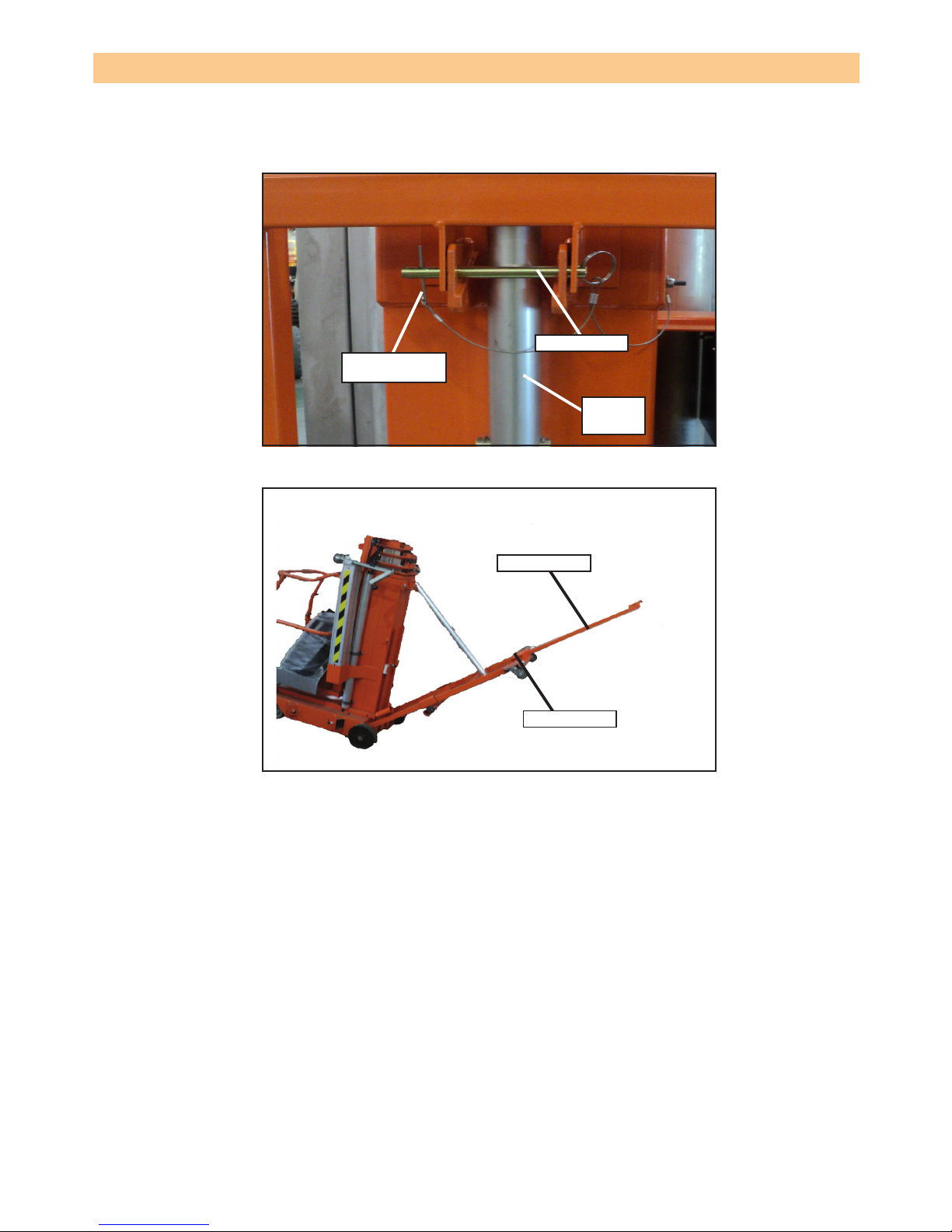
Page 2 - 17UL25/UL32/UL40
TRANSPORTATION
Figure 2-11: Loader in load position.
Figure 2-12: handle positioning.
Loader channel
Retaining pin
Loader
Gravity hook
Loader support
bracket
Handle bar
Handle
Retaining pin
Page 26

Page 2 - 18 UL25/UL32/UL40
TRANSPORTATION
LOADING
1. Raise the loader support brackets and engage the retaining pin in the top hole of the loader
channel.
2. Secure the loader to the loader support bracket with the gravity hook.
3. Position the unit so that the back of the machine comes into contact with the tailgate or vehicle
bed.
4. Release the gravity hook and slide the loader down until it comes into contact with the tailgate
or vehicle bed. Then, re-position the loader support bracket so that the retaining pin is in the
rst available hole above the loader.
5. Release the locking pin and pull the T-handle out until the locking pin engages the hole in the
end of the T-handle.
6. Lift up on the T-handle using the loader as a pivot until the unit rotates to a horizontal position
in the vehicle bed.
7. Push the base of the unit towards the front of the vehicle bed. The machine will slide on the
loader until the rear wheels are on the bed. The unit may then be rolled on the rear wheels and
upper casters.
8. Re-turn the T-handle to the stored position making sure that the locking pin engages the Thandle.
9. Secure the unit with suitable tie straps using the forklift pockets located under the base of the
tilt back frame.
!
C A U T I O N
!
To prevent damage to the mast assembly, do not place
rope or tie straps across the mast assembly when secur-
ing the unit for transportation.
DO NOT overtighten the rope or tie straps otherwise
damage to the machine will result.
UNLOADING
1. Unsecure the unit.
2. Release the locking pin and pull the T-handle out until the locking pin engages the hole at the
end of the T-handle.
3. Roll the unit back until the rear wheels are off the edge of the tailgate or vehicle bed.
4. Pull downward on the T-handle allowing the unit to slide on the loader.
• As the unit stops sliding on the loader, it will pivot on the loader to an upright position.
• Gradually counterbalance the unit’s weight by applying an upward force on the T-handle.
This allows the unit to settle gently on the wheels avoiding undue impact on the unit.
5. Return the T-handle to the stored position making sure that the locking pin engages the T-handle.
!
W A R N I N G
!
Ensure that the loader fully engages the
tailgate or vehicle bed.
Page 27

Page 2 - 19UL25/UL32/UL40
TRANSPORTATION
PASSAGE THROUGH A DOORWAY
The UL machine is equipped with a castered rear tilt back assembly. When the unit is tilted back
onto this support frame, the overall height is reduced to allow the unit to pass through a standard
doorway.
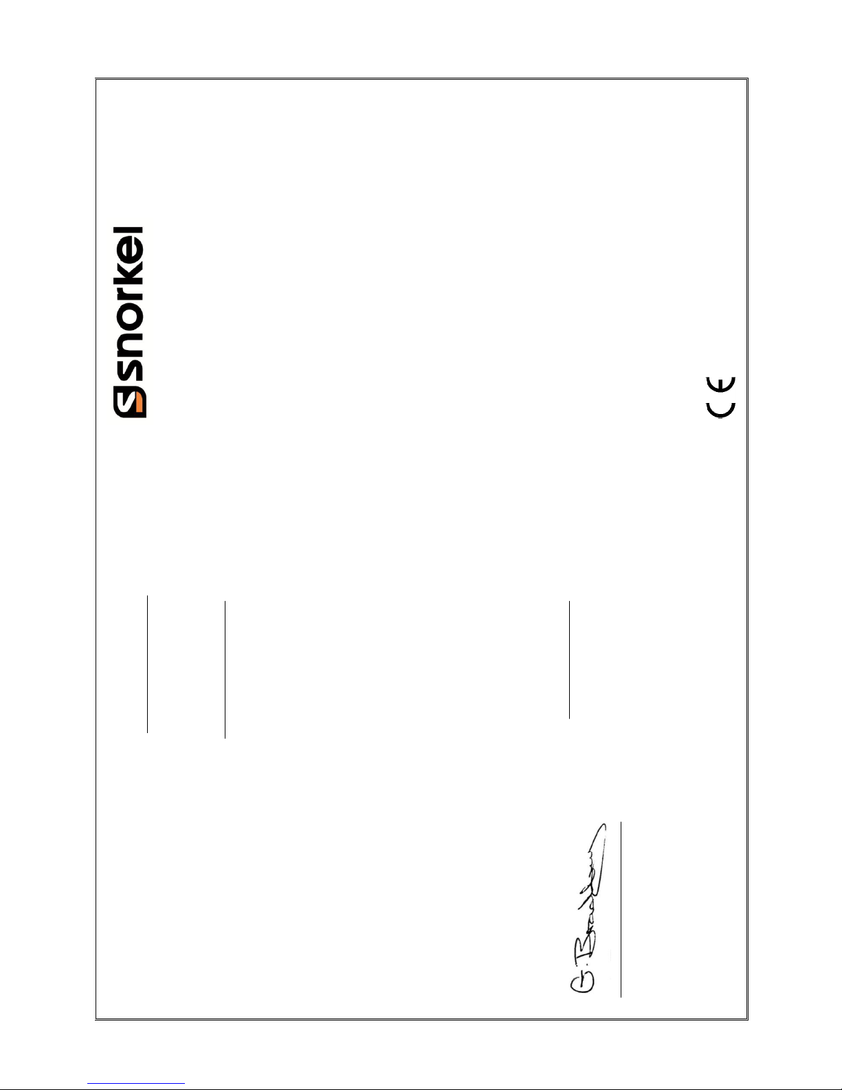
LOWERING
!
C A U T I O N
!
Before tilting the machine unto the rear tilt back as-
sembly, be sure that the retaining pin is fully inserted
with the hair pin retainer and the cylinder assembly is
fully extended.
DO NOT drop the tilt back frame. Keep out from under
the tilt back frame and machine when tilting.
1. Ensure that the area is clear of personnel and obstructions.
2. While holding the tilt back frame, remove the hair pin retainer and the retaining pin.
3. Lower the tilt back frame until the hole in the cylinder assembly align with the upper mounting
bracket pin hole. Secure the cylinder assembly to the upper mounting bracket using the retaining pin and hair pin retainer.
4. Extend the tilt back handle to the tilt/lift position by releasing the locking pin and pulling the
handle out of the tilt back assembly until the locking pin engages.
5. Push down on the tilt back handle until the unit comes to rest on the tilt back frame.
• As the mast tilts back, counterbalance the machine’s weight by increasing upward force
on the end of the tilt back handle. This allows the machine to gently come to rest on the tilt
back casters.
6. Pull down on the handle on the back of the mast to compress the cylinder assembly.
7. Return the tilt back handle to the storage position, making sure that the locking pin engages
the handle.
RAISING
1. Lift up on the mast handle to extend the cylinder assembly.
2. Fully engage the tilt back handle until the locking pin engages.
3. Lift up on the tilt back handle.
• As the mast approaches vertical, counterbalance the machine’s weight by increasing
downward force on the end of the tilt back handle. This allows the machine to settle gently
on the front casters.
4. Return the tilt back handle to the storage position, making sure that the locking pin engages
the handle.
5. While holding the tilt back frame, remove the retaining pin and raise the tilt back assembly to
the stowed position.
6. Secure with the retaining pin, making sure that the retaining pin is fully inserted and that the
hair pin retainer is installed.
Page 28
Page 2 - 20 UL25/UL32/UL40
TRANSPORTATION
Figure 2-13: Cylinder secured with retaining pin.
Figure 2-14: Lowering and raising with the tilt back handle.
Retaining pin
Cylinder
assembly
Hair pin retainer
Tilt back handle
Retaining pin
Page 29

Page 2 - 21UL25/UL32/UL40
MAINTENANCE
BATTERY MAINTENANCE
!
W A R N I N G
!
Hazard of explosive gas mixture. Keep sparks, ame and smoking
material away from batteries.
Always wear safety glasses when working near batteries.
Battery uid is highly corrosive. Thoroughly rinse away any spilled uid with
clean water.
Always replace the batteries with Snorkel batteries or manufacturer approved replacements weighing 22 kg (48 lbs.) each.
Use the following procedure to ensure battery maintenance.
1. Check the battery uid level daily especially if the work platform is being used in a warm, dry
climate.
2. If the electrolyte level is lower than 10 mm (3/8") above the plates, add distilled water only. Do
not use tap water due to its high mineral content since it will shorten battery life.
3. Keep the terminals and tops of the batteries clean.
4. Refer to the service manual to extend battery life and for complete service instructions.
BATTERY CHARGING
!
W A R N I N G
!
Charge the batteries in a well ventilated area. Do not charge the batteries when
the work platform is near a source of spark or ames.
Permanent damage to the batteries will result if the batteries are not
immediately recharged after discharging. Never disconnect the cables from the
batteries when the charger is operating. Keep the charger dry.
Use the following procedure to charge the batteries after use.
1. Check the battery uid level. If the battery uid level is lower than 10 mm (3/8") above the
plates, add distilled water only.
2. Verify the charger voltage switch is set to 12 volts.
3. Connect an appropriate extension cord to the charger plug. Plug the extension cord into a
properly grounded outlet of proper voltage and frequency.
NOTE: The battery charger circuit must be used with a GFI (Ground fault interrupt) outlet.
NOTE: Do not operate the machine while the charger is plugged in.
Page 30

Page 2 - 22 UL25/UL32/UL40
HYDRAULIC FLUID
The hydraulic uid reservoir is located under the power unit cover.
NOTE: Never add uid if the platform is elevated.
HYDRAULIC FLUID CHECK
1. Make sure that the platform is fully lowered.
2. Open the chassis door.
3. Check the uid level using the gauge on the dipstick.
4. To add hydraulic uid, remove the ller cap.
5. Add the appropriate hydraulic uid to raise the level to the end of the dipstick.
MAINTENANCE
Page 31

Page 2 - 23UL25/UL32/UL40
The complete inspection consists of periodic visual and operational checks along with periodic minor adjustments that assure proper performance. Daily inspection will prevent abnormal wear and
prolong the life of all systems. The inspection and maintenance schedule should be performed by
personnel who are trained and familiar with mechanical and electrical procedures.
!
W A R N I N G
!
Before performing preventative maintenance, familiarize yourself with the
operation of the machine. Always block the elevating assembly whenever it is
necessary to perform maintenance while the platform is elevated.
The daily preventative maintenance checklist has been designed for machine service and maintenance. Photocopy the checklist page and use the checklist when inspecting the machine.
INSPECTION AND MAINTENANCE
Page 32

Page 2 - 24 UL25/UL32/UL40
INSPECTION AND MAINTENANCE
Table 2-2: Daily preventative maintenance
checklist
DAILY PREVENTATIVE MAINTENANCE SCHEDULE
MAINTENANCE TABLE KEY PREVENTATIVE MAINTENANCE REPORT
Y = Yes/Acceptable Date: ______________________________
N = No/Not Acceptable Owner: _____________________________
R = Repaired/Acceptable Model #: ____________________________
Serial #: ____________________________
Serviced by: _________________________
Operator’s
Manual
Check that the operators manual is in
the manual holder and all pages are
intact and readable
Labels &
Decals
Check that labels and decals are in
place, intact and readable
Control
Cable
Check the exterior of the cable for
pinching, binding or wear.
Mast
Assembly
Inspect for bends, cracks or loose
rivets.
Battery
System
Check electrolyte level
Check battery cable condition
Check terminals are clean and connectors are tight
Check charger condition and operation
Charge batteries
Hydraulic
uid
Check oil level
Hydraulic
system
Check all ttings are tight and there are
no leaks
Drive motors Check for operation and leaks
Hydraulic
pump
Check ttings are secure and there are
no leaks
Emergency
lowering
Operate the emergency lowering valve
and check for serviceability.
Controller Check switch operation
Platform
deck and
rails
Check fasteners are in place, correctly
tightened and not damaged
Check the structure and welds for damage, deformation, corrosion and cracks
Check condition of deck (no damage,
deformation, corrosion or cracks
Check entry gate closure functions
correcly
Elevating
assembly
Inspect for external damage, dents, loose
rivets or cracks.
Check the structure and welds for damage, deformation, corrosion and cracks
Chassis Check operation of outrigger interlocks
Check castors for damage
Check hoses for pinch or rubbing points
Check welds for cracks
Lift Cylinders Check for leaks
Harness
anchor point
Check fasteners are secure
Check for damage, deformation, corrosion
and cracks
System function inspection
Conduct system function inspection (see
system function inspection pocedure)
Emergency
stops
Check that the emergency stop button on
the basket panels opertates correctly
Check that the emergency stop button
on the ground control panel operates
correctly
Alarm Check that the alarm sounds when
activated
* NOTE: Use ISO #46 during summer
and ISO #32 during winter
COMPONENT
INSPECTION OR SERVICES
Y N
R
COMPONENT
INSPECTION OR SERVICES
Y
N
R
Page 33

Page 2 - 25UL25/UL32/UL40
SPECIFICATIONS
ITEM UL25 UL32 UL40
Platform capacity 159 kg (350 lbs.) 136 kg (300 lbs.) 136 kg (300 lbs.)
Occupants 1 PERSON 1 PERSON 1 PERSON
Height
Working height 9.62 m (31.6 ft.) 11.75 m (38.5 ft.) 14.19 m (46.6 ft.)
Maximum platform height 7.62 m (25 ft.) 9.75 m (32 ft.) 12.19 m (40 ft.)
Minimum platform height 38 cm (15") 38 cm (15") 38 cm (15")
Dimensions
Overall weight 390 kg (860 lbs) 435 kg (960 lbs) 470 kg (1040 lbs)
DC option weight 29 kg (64 lbs.) 29 kg (64 lbs.) 29 kg (64 lbs.)
Overall width (outriggers extended) 2.06 m (81") 2.06 m (81") 2.95 m (116")
Overall length (outriggers extended) 1.98 m (78") 1.98 m (78") 2.84 m (112")
Stowed dimensions
Vertical height 1.98 m (78") 2.53 m (100") 2.90 m (114")
Width 74 cm (29") 74 cm (29”) 74 cm (29”)
Depth 1.24 m (49") 1.32 m (52") 1.32 m (52")
Diagonal storage height 1.94 m (76") 1.94 m (76") 2 m (79")
Diagonal storage length 2.59 m (102") 2.72 m (107") 3.05 m (120")
System voltage
AC electric motor 120 VAC 60 Hz or 220 VAC 50/60 Hz
DC electric power source 1-12 volt battery, group 27 105 Amp/hrs. minimum weight 22 kg (48 lbs.)
Battery charger Automatic, 120 VAC 60 Hz or 220 VAC 50 Hz
Output: 10 Amp, 12 volts DC
Hydraulic tank capacity 5.7 litres (1.5 gal)
Maximum hydraulic
pressure
165 bar (2400 PSI)
Hydraulic Fluid
Normal temperature: above 0° C
[32 F]
ISO #46
Low temperature: below 0° C [32 F] ISO #32
Extreme temperature: below -17° C
[ 0 F]
ISO #15
Control system Push button lift and lower, red mushroom emergency stop switch
Guardrails 1.1 m (43.5") high
Toeboard 152 mm (6") high
Maximum chassis inclination 1.0 degrees in all directions
Outrigger loading 170 kg (374 lbs.)
Vibration Whole body vibration < 0.5 m/s2, Handarm vibration < 2.5 m/s
2
Sound pressure 68 dB (A) at control station
Operating temperature range -20° C to +50° C
Table 3: UL25/32/40 Specication
NOTE: Specications are subject to change without notice. Hot weather or heavy use may affect
performance. Refer to the service manual for complete parts and service information. This machine meets or exceeds all applicable OSHA and ANSI A92.6 - 1999.
Page 34

Page 2 - 26 UL25/UL32/UL40
End of Life Waste Advice Chart :
No
Your waste can't be recycled as scrap metal.
No
Is the metal:
YesAluminum,
Copper,
Iron, Yes
Lead,
Steel, or Zinc?
No
Your waste is a HAZARDOUS WASTE Follow your
YesYes
Is your waste (not Leaking / damaged)?Is your waste (Leaking / damaged)?
No No
Yes
Yes
Is your waste?
No *Any type of oil contaminated with a hazardous chemical
Is your waste:Yes
* Motor Oil Yes* Degreasing solvents Your waste is a HAZARDOUS WASTE
Is your waste?
* Power Steering Fluid * Naptha Yes
Yes* Diesel Fuel No * Coolant from chillers/HAVC systemsNo* Transformer oil
* Gear Oil * Brake Fluid
* Hydraulic Oil * Radiator Flush
* Kerosene (#3,#4, & #6) * Deicers
Oils can NOT be disposed down the drain * Oily Water
(even if they are not hazardous waste).
No
Is your waste:
Yes* Armer cable
* Electrical Components
* Electrical circuit boards
No
Is your waste:
YesPolymer wear pads
Tyres
Hydraulic hoses
Is the waste: a Polymer, Tyre or Hose ?
Your waste is a HAZARDOUS WASTE Follow your
HAZARDOUS WASTE
Is the waste: an electrical component
or wiring ?
Is the waste: an
Your End of life waste is a HAZARDOUS WASTE
disposal of HAZARDOUS WASTE
been depoluted
IIs the waste: A used
HAZARDOUS
WASTE
Your waste should be RECYCLED following your
Is the waste: A solid metal ?
HAZARDOUS WASTE
RECYCLED according to
These are non-hazardous and can be
placed in regular trash, however, in an
friendly you may chouse to collect
RECYCLING purposes.
should be RECYCLED according to the universal
WASTE DISPOSAL AND REMOVAL
Page 35

Page 3 - 1UL25/UL32/UL40
SERVICE AND REPAIR
CONTENTS
INTRODUCTION 3-2
SPECIAL TOOLS 3-2
PREVENTATIVE MAINTENANCE 3-2
PREVENTATIVE MAINTENANCE TABLE 3-3
LUBRICATION 3-4
CASTERS 3-4
CHAINS 3-4
SCREW JACKS 3-4
HYDRAULIC OIL RESERVOIR 3-4
BATTERY MAINTENANCE 3-5
BATTERY INSPECTION AND CLEANING 3-5
BATTERY CHARGING 3-5
BATTERY CELL EQUALIZATION 3-6
SETTING SYSTEM RELIEF VALVE 3-6
MAST ASSEMBLY/DISASSEMBLY 3-7
PLATFORM ASSEMBLY REMOVAL 3-7
PLATFORM ASSEMBLY 3-12
PLATFORM SUPPORT ASSEMBLY 3-13
SEQUENCING STRAP INSTALLATION 3-13
CYLINDER ASSEMBLY 3-13
SEAL REPLACEMENT 3-13
ORIFICE VALVE CLEANING 3-15
CYLINDER REMOVAL 3-17
CYLINDER INSTALLATION 3-17
TORQUE SPECIFICATIONS 3-18
HYDRAULIC COMPONENTS 3-18
FASTENERS 3-19
Page 36

Page 3 - 2 UL25/UL32/UL40
INTRODUCTION
This section contains instructions for the maintenance of the work platform. Refer to the general
information section for information relevant to all Snorkel work platform and help in diagnosing and
repair of the machine.
The preventative maintenance table should be used at intervals specied by Snorkel or that of Local/National regulations to ensure the aerial platform is in good condition for use.
SPECIAL TOOLS
The following is a list of special tools that are required to perform certain maintenance procedures.
These tools may be purchased from local dealers.
Description Part Number
Spanner Wrench for UL 25/32/40 062521-010
Strap Wrench 062482-000
Tie Rod Tensioner ( 2 required) 062738-000
Tensioner Bracket (2 required) 062739-000
EZCal Caliberation & Diagnostic Tool 3072123
PREVENTATIVE MAINTENANCE
The complete inspection consists of periodic visual and operational checks together with all necessary adjustments to assure proper performance. Daily inspection will prevent abnormal wear and
pro-long the life of all systems. The inspection and maintenance schedule is to be performed at
regular intervals. Inspection and maintenance shall be performed by personnel who are trained
and familiar with mechanical and electrical procedures. Complete descriptions of the procedures
are stated in the table 3-2.
The preventative maintenance table has been designed to be used for machine service and maintenance repair.
SERVICE AND REPAIR
!
W A R N I N G
!
Be sure to read, understand and follow all information
stated in the operation section of this manual before
attempting to operate or perform service on any work
platform.
!
D A N G E R
!
Never perform service on the work platform in the elevating
assembly area while the platform is elevated without rst blocking
the elevating assembly. DO NOT stand in the elevating assembly
area while deploying or storing the brace.
Table 3-1: List of special maintenance tools.
!
W A R N I N G
!
Before performing preventative maintenance, it is important
to get familiar with the operation of the machine.
Never enter the area below the platform when the platform
is elevated.
Page 37

Page 3 - 3UL25/UL32/UL40
PREVENTATIVE MAINTENANCE TABLE
INTERVAL
Daily = each shift or everyday
30 d = every 30 days
3 m = every 3 months
1 y = every 1 year
Y = Yes/Acceptable
N = No/Not Acceptable
R = Repaired/Acceptable
DO NOT t replacement parts other than genuine components without express written approval
from the manufacturer.
SERVICE AND REPAIR
PREVENTATIVE MAINTENANCE REPORT
Date:
Owner:
Model #:
Serial #:
Serviced By:
Service Interval:
COMPO-
NENT
INSPECTION OR SERVICES INTER-
VAL
Y N R
Battery
System
(DC units
only)
Check electrolyte level Daily
Check specic gravity 30d
Charge batteries Daily
Check charger condition &
operation
Daily
Clean exterior 3m
Check battery cable condition Daily
Clean terminals 3m
Hydraulic
Oil
Check oil level Daily
Drain and replace oil (ISO
#46)
1y
Hydraulic
system
Check for leaks Daily
Check line connections 30d
Check hoses for exterior wear 30d
Emergency
hydraulic
System
Open the emergency lower-
ing valve and check for
serviceability
3m
Emergency
Down
Check procedure for emer-
gency down batteries
3m
A.C. Only: Replace emergen-
cy down batteries in upper
control box
1y
Controls Check condition and opera-
tion
Daily
Control
Cable
Check the exterior of the
cable for pinching, binding or
wear
Daily
Platform
deck and
rails
Check fasteners for proper
torque
Daily
Check welds for cracks Daily
Check condition of deck Daily
Check entry way closure Daily
Hydraulic
Pump
Check for tting leaks Daily
Wipe clean 30d
Check for leaks at mating
surfaces
30d
Check mounting bolts for
proper torque
30d
COMPO-
NENT
INSPECTION OR SER-
VICES
INTER-
VAL
Y N R
Elevating
Assembly
Inspect for external damage, dents loose rivets or
cracks
Daily
Check chains and
sheaves for wear
3m
Inspect and adjust se-
quence straps
30d
Chassis
Check cables for pinch
or rubbing points
Daily
Check component
mounting for proper
torque
6m
Check welds for cracks Daily
Check casters for dam-
age
Daily
Lift Cylin-
der
Check for leaks Daily
Check for proper torque 30d
Entire Unit
Perform pre-operation
inspection
Daily
Check for and repair col-
lision damage
Daily
Lubricate 3m
Check fasteners for
proper torque
3m
Check for corrosion;
remove and repaint
3m
Labels Check for peeling, miss-
ing or unreadable labels
& replace
Daily
Entire
unit
Check for and repair col-
lision damage
Daily
Check fasteners for
proper torque
3m
Check for corrosion-
remove and paint
6m
Lubricate 30d
Table 3-2: Preventative maintenance checklist
A thorough investigation should be carried out every 6 months.
NOTE: Frequency and extent of periodic examinations may depend on national regulations.
Page 38

Page 3 - 4 UL25/UL32/UL40
SERVICE AND REPAIR
LUBRICATION
Refer to gure 3-1 for the location of items that require lubrication service. Use an aerosol chain
lubricant for all components to be lubricated.
CASTERS
Using a grease gun, apply 1 or 2 shots of multi-purpose bearing grease to each zerk tting. Swivel
casters have two zerk ttings, one at the wheel bearing and one at the swivel.
CHAINS
1. Ensure that the platform is fully lowered.
2. Apply enough aerosol chain lubricant to exposed section of chain to allow lubricant to run down
chain.
SCREW JACKS
Apply a moderate amount of aerosol chain lubricant to each screw jack assembly.
HYDRAULIC OIL RESERVOIR
To change oil in the reservoir, rstly verify that the platform is fully lowered.
1. Remove the hydraulic reservoir from the pump by removing four screws and four grip plates.
2. Provide a suitable container as an ideal reservoir for a 5.7 litres (1.5 U.S. gallon) capacity and
dispose of hydraulic uid properly. Contact local oil recyclers for more information.
NOTE: Ensure the o-ring is in place on the pump when installing the hydraulic reservoir.
3. Reinstall hydraulic reservoir to pump assembly with grip plates and screws.
Figure 3-1: Locations for lubrication.
1 Chains
2 Casters
3 Rear Wheels
4 Screw Jacks
3
1
2
5&6
4
1 Motor
2 Pump
3 Reservoir
4 Breather/Dipstick
5 Capscrew (under pump)
6 Grip Plate (under pump)
Figure 3-2: Hydraulic Power Unit.
Page 39

Page 3 - 5UL25/UL32/UL40
SERVICE AND REPAIR
4. Fill hydraulic reservoir through the dipstick hole with ISO #46 hydraulic uid. The hydraulic res-
ervoir has a 5.7 litres (1.5 U.S. gallon capacity. Ensure that the oil is visible on the end of the
dipstick.
BATTERY MAINTENANCE - DC UNITS ONLY
Electrical energy for the motor is supplied by a 12 volt battery. Proper care and maintenance of the
battery and motor will ensure maximum performance from the lift.
!
W A R N I N G
!
Hazard of explosive gas mixture. Keep sparks, ames and smoking materials away
from batteries.
Always wear safety glasses when working with batteries.
Battery uid is highly corrosive. Rinse away any spilled uid thoroughly with clear
water.
BATTERY INSPECTION AND CLEANING
Check the battery uid level daily, especially if the work platform is being used in a warm, dry
climate. If required, add distilled water only. Use of tap water with high mineral content will shorten
battery life.
!
W A R N I N G
!
If the battery water level is not maintained, a full charge cannot be achieved. This
will create a low discharge rate which will damage the motor/pump unit and void the
warranty.
The battery should be inspected periodically for signs of cracks and in some cases, electrolyte
leakage and corrosion of the terminals. Inspect cables for worn spots or breaks in the insulation
and for broken cable terminals.
Clean battery that shows signs of corrosion at the terminals or onto which the electrolyte has over-
owed during charging. Use a baking soda solution to clean the battery, taking care not to get the
solution inside the cells. Rinse thoroughly with clear water. Clean battery and cable contact sur-
faces to a bright metal nish whenever a cable is removed.
BATTERY CHARGING
Charge the battery at the end of each work shift or when the battery has been discharged; which-
ever occurs rst.
!
C A U T I O N
!
Charge the battery in a well ventilated area. DO NOT charge the battery
when the lift is in an area containing sparks or ames.
Permanent damage to the battery will result if not immediately recharged
after discharging.
NEVER leave the charger operating unattended for more than two days.
NEVER disconnect cables from the battery when the charger is operating.
Keep the charger dry.
Page 40

Page 3 - 6 UL25/UL32/UL40
SERVICE AND REPAIR
When night air temperatures fall below 18°C (65°F), a battery charged in an unheated area should
be placed on charge as soon as possible after use. Under such conditions, a 4 hour charge once a
week in the early afternoon will improve the battery life. Use the following procedure to charge the
battery.
1. Check battery uid level. If the electrolyte level is lower than 10mm (3/8 inches) above the plates,
add distilled water only.
2. Verify charger voltage switch is set to 12 volts.
3. The battery charger is located at the rear of the mast. Connect an extension cord (a minimum
of 1.5mm2 [12 gauge] conductor and a maximum length of 15m [50 feet]) to the charger plug.
Connect the other end of the extension plug to a properly grounded outlet of proper voltage and
frequency.
4. Set charger control to “conventional” setting. Charger ammeter should indicate charger rate.
5. When battery is fully charged, charger automatically turns itself off. Disconnect the extension
cord.
BATTERY CELL EQUALIZATION
The specic gravity of the electrolyte in the battery cells should be equalized monthly. To do this;
• Charge batteries as outlined in battery charging.
• After the initial charge, check the electrolyte level in all cells and add distilled water as neces-
sary.
• Turn the charger on for an additional 8 hours. During this charge, the charging current will be
low (four amps) as cells are equalizing.
• After equalization, the specic gravity of all cells should be checked with a hydrometer. The
temperature corrected specic gravity in this state should be 1.260. If any corrected readings
are below 1.230, the battery should be replaced.
Do not check the specic gravity in a cell to which water has just been added. If there is not enough
electrolyte in a fully charged cell to obtain a sample for the hydrometer, add water and continue
charging for 1 to 2 hours to adequately mix the water with the electrolyte.
SETTING SYSTEM RELIEF VALVE
Check the hydraulic system pressure whenever the pump or relief valve has been serviced or replaced.
Battery
Charger
Figure 3-3: Battery Charger.
Page 41

Page 3 - 7UL25/UL32/UL40
SERVICE AND REPAIR
!
W A R N I N G
!
The hydraulic oil may be of sufcient temperature to
cause burns. Wear safety gloves and safety glasses
when handling hot oil.
1. Install the outriggers and level the unit as normal (refer to the operators manual for operating
instructions). Operate the hydraulic system for 5-10 minutes to warm up the hydraulic oil.
2. Remove the cover from the power unit assembly.
3. Place the rated safe working load for the machine (as stated under specications in the operation
section) on the platform. Do not use personnel as safe working load for this procedure.
4. Install a pressure gauge on the gauge port.
5. Remove the cap from the system relief valve (refer to gure 3-4) and turn the adjustment screw
counterclockwise, 2 full turns.
6. Operate controls to elevate the machine. Note that the machine will not raise until the relief valve
is properly adjusted.
7. Turn the system relief valve clockwise (refer to gure 3-4) until the machine begins to rise.
8. Elevate the platform fully and verify that the pressure does not exceed 165 bar (2400 PSI) at any
time during the lift cycle.
9. Replace cap on the system relief valve and reassemble cover.
Relief Valve
Gauge Port
MAST ASSEMBLY/DISASSEMBLY
Using a suitable lifting device, lower the work platform into a horizontal position (refer to gure 3-5).
If possible, place the machine unto a sturdy work table using a forklift.
!
W A R N I N G
!
Never attempt to lower the lift into a horizontal position
without the use of a suitable lifting device; bodily injury
or damage to the machine may result.
NOTE: Mark all components as they are removed to ease with re-installation in the correct
location and sequence.
PLATFORM ASSEMBLY REMOVAL
1. Extend elevating assembly far enough to expose the eight screws attaching the cage support
assembly to stage 6 by opening the emergency lowering valve and pulling on the cage guardrail.
2. Remove cover from the front of the platform assembly.
Figure 3-4: System Relief Valve.
Page 42

Page 3 - 8 UL25/UL32/UL40
SERVICE AND REPAIR
Forklift
3. Remove the cotter pins and chain retaining pins from the top front of stage 5.
4. Loosen screws from the strap retainer on the top casting of stage 5. Pull the strap free of the
retainer.
5. Remove the cage support screws, slide the cage support out of the sixth stage mast and set
aside. It should not be necessary to remove the pinch shield. Be careful not to damage the control cable.
NOTE: To remove the platform assembly from the cage support assembly, follow the steps
6-10 below.
6. Remove cable sheaves from the cage support weldment and strain reliefs from the top casting
of stage 5.
7. Loosen screws from the strap retainer on the platform assembly weldment and free strap from
the retainer.
8. Remove the 2 screws and washers holding the stop bracket located on the top of platform assembly weldment. Remove the stop bracket.
9. Slide the cage support weldment out of the top of the platform assembly weldment.
10. The slide bearings in platform assembly may now be inspected or replaced if necessary.
Use the following procedure in the sequence provided to disassemble the masts.
#6 MAST
1. Remove sequence strap retainer on the top of #4 mast.
2. Remove the allen head screws holding the top mast bearings between the #5 and #6 mast. Remove the top mast bearings.
3. Slide #6 mast out of #5 mast. As mast is removed, the bottom four mast bearings will fall out. Its
important to note their orientation for re-assembly.
4. Disconnect the chain from the top of #4 mast.
#5 MAST
1. Remove the sequence strap retainer on the top of #3 mast.
2. Remove the allen head screws holding the top mast bearings between the #4 and #5 mast. Remove the top mast bearings.
3. Slide #5 mast out of #4 mast. As the mast is removed, the bottom four mast bearings will fall out.
Its important to note their orientation for re-assembly.
4. Disconnect the chain from the top of #3 mast.
#4 MAST
1. Remove sequence strap retainer on the top of #2 mast.
2. Remove the Allen head screws holding the top mast bearings between the #3 and #4 mast. Remove the top mast bearings.
Figure 3-5: Lifting/Lowering Procedure.
Page 43

Page 3 - 9UL25/UL32/UL40
3. Slide #4 mast out of #3 mast. As mast is removed, the bottom four mast bearings will fall out;
note their orientation for re-assembly.
4. Disconnect the chain from the top of the #2 mast.
5. Remove the cylinder by following instructions provided under the section named “CYLINDER
ASSEMBLY”.
#3 MAST
1. Remove the sequence strap retainer on the top of #1 mast.
2. Remove the Allen head screws holding the top mast bearings between the #2 and #3 mast. Remove the top mast bearings.
3. Slide #3 mast out of #2 mast. As mast is removed, the bottom four mast bearings will fall out. Its
important to note their orientation for re-assembly.
#2 MAST
1. Remove the Allen head screws holding the top mast bearings between the #1 and #2 mast. Remove the top mast bearings.
2. Slide the #2 mast out of the #1 mast. As mast is removed, the bottom four mast bearings will fall
out. Its important to note their orientation for re-assembly.
SERVICE AND REPAIR
Page 44

Page 3 - 10 UL25/UL32/UL40
SERVICE AND REPAIR
Figure 3-6: Mast Assembly, Strap and Chain Detail.
Page 45

Page 3 - 11UL25/UL32/UL40
SERVICE AND REPAIR
Figure 3-7: Mast Assembly, Bearing Detail.
Page 46

Page 3 - 12 UL25/UL32/UL40
PLATFORM ASSEMBLY
NOTE: Use WD-40 lubricant as necessary to aid with re-assembly.
#2 MAST
1. Set #2 mast in place.
2. Install bottom lower bearings.
3. Install bottom upper bearings.
4. Slide #2 mast in all the way except 30-38 cm (12-15 inches).
5. Install top bearings and secure with retaining screws using loctite 242 or equivalent on the
threads.
6. Slide #2 mast in completely.
#3 MAST
1. Set #3 mast in place with the sequencing strap inside.
2. Install bottom lower bearings.
3. Install bottom upper bearings.
4. Slide #3 mast in all the way except 30-38 cm (12-15 inches).
5. Install top bearings and secure with retaining screws using loctite 242 or equivalent on the
threads.
6. Place a 25 cm (10 inches) long wood block between #3 and #2 masts, slide #3 mast down tight
against block. Pull sequencing strap completely out of the bottom assembly.
7. Install cylinder assembly by following instructions under “CYLINDER ASSEMBLY” section.
#4 MAST
1. Set #4 mast in place with the sequencing strap inside and the chains on the bottom.
2. Install bottom lower bearings.
3. Install bottom upper bearings.
4. Slide mast #4 in, making sure chains are not twisted.
5. Install top bearings and secure with retaining screws using loctite 242 or equivalent on the
threads.
6. Install chains around #3 sheave and down through #3 casting. Secure to #2 casting with new roll
pins.
7. Use a centre punch to dimple pin hole after roll pins are installed.
#5 MAST
1. Set #5 mast in place with the sequencing strap inside.
2. Install bottom lower bearings.
3. Install bottom upper bearings.
4. Slide #5 mast in, making sure chains are not twisted.
5. Install top bearings and secure with retaining screw using loctite 242 or equivalent on the threads.
6. Install chains around #4 sheaves and down through the casting. Secure to #3 casting with new
roll pins.
7. Use a center punch to dimple pin holes after all roll pins are installed.
8. Slide mast in, leaving 25 cm (10 inches) exposed.
#6 MAST
1. Set #6 mast in place with the sequencing strap inside.
2. Run the remaining sequencing strap from the platform to the assembly through the slot in the
bottom of stage #6 and up through the inside. Leave just enough slack on the outside to reach
the attachment point at the top of stage #5.
3. Install the bottom lower bearings.
4. Install the bottom upper bearings.
5. Slide #6 mast in, making sure the chains are not twisted.
6. Install the top bearings and secure with retaining screws using loctite 242 or equivalent on the
threads.
7. Install the #6 chain around the #5 sheave and through the casting secured to the #4 casting with
SERVICE AND REPAIR
Page 47

Page 3 - 13UL25/UL32/UL40
new roll pins.
8. Use a centre punch to dimple pin holes after all roll pins are installed.
9. Pull the sequencing strap attached to the bottom of mast #6 out through the bottom of the mast
assembly. Be sure not to pull the strap that is attached to the top of mast #5.
PLATFORM SUPPORT ASSEMBLY
1. Slide the cage support weldment into the top of the platform assembly weldment.
2. Install the stop bracket and retaining screws/washers.
3. Feed chains over sheave.
4. Install cable sheaves with cables to the top of the cage support weldment.
5. Feed sequencing strap from inside mast #6 over sheave and out through the slot in the top of
the cage support weldment.
6. Install cage support weldment to mast #6 using 8 screws and tighten.
7. Attach chains to #5 casting front using new cotter pins.
SEQUENCING STRAP INSTALLATION
NOTE: When installing straps, make sure they are not twisted.
1. Feed sh tape up through the bottom slot in the cage support weldment and out through the top
slot.
2. Attach strap to the sh tape and pull out through bottom slot.
3. Feed sh tape down through the opening in the front of the platform support weldment and out
through the bottom of the platform support weldment.
4. Attach strap to the sh tape and pull out through the opening. Attach the strap to the platform
support weldment, pull tightly and secure with strap clamp and screws using loctite 242 or equivalent on the threads.
5. Feed #6 strap up through the mast between fourth and fth stages with a sh tape.
6. Feed #5 strap up through the mast between third and fourth stages with a sh tape.
7. Feed #4 strap up through the mast between third and second stages with a sh tape.
8. Feed #3 strap up through the mast between rst and second stages with a sh tape.
9. Install strap #6 to #4 top casting.
10. Install strap #5 to #3 top casting.
11. Install strap #4 to #2 top casting.
12. Install strap #3 to the top of #1 mast weldment.
13. Install the strap clamps and retaining screws using loctite 242 or equivalent on the threads. Pull
straps tight while tightening retaining screws.
CYLINDER ASSEMBLY
SEAL REPLACEMENT
NOTE: The lift cylinder seal can be accessed from the bottom of the lift without removing the
cylinder assembly.
Using a suitable lifting device, lower the work platform into a horizontal position (refer to Figure 3-5).
If possible, place the machine on a sturdy work table using a forklift.
!
W A R N I N G
!
Never attempt to lower lift into a horizontal position without the
use of a suitable lifting device as this can lead to bodily injury
or damage to the machine .
1. Remove cylinder mounting plate fasteners and retaining ring.
2. Remove tie rod nuts and count the number of turns required to bring the nut ush with the tie
rod end and record for reference during installation. The tension on the tie rods maintain the left/
right positioning of the cylinder within the mast assembly. Re-installing the nuts with the proper
tension will speed up adjustment later.
3. Remove the cylinder mounting plate. Be careful not to allow the tie rods to suck back inside the
SERVICE AND REPAIR
Page 48

Page 3 - 14 UL25/UL32/UL40
mast assembly. Replace the nuts on the tie rod ends temporarily to prevent this.
4. Remove the hydraulic line from the cylinder tting and cap the cylinder tting to prevent contami-
nants from entering the cylinder.
!
C A U T I O N
!
Marring the surface of the cylinder rod will dam-
age cylinder seals and cause leakages. Use a strap
wrench to prevent rod damage.
5. Extend the cylinder rod at least 12 inches by hand. Apply heat to rod near end cap to loosen
loctite.
!
W A R N I N G
!
Wear safety glasses and heat resistant gloves when operating torch. Do not touch hot surfaces without proper
protection.
6. Using a strap wrench - 062482-000 to secure the cylinder rod, unscrew the cylinder rod end. If
necessary, thread a 9/16 x 18 bolt into end cap port to use as a lever. Remove rod end cap and
orice/bleeder tube assembly.
7. Remove the seal retainer, using the spanner wrench - 062521-010.
8. Clean all sealing surfaces with a solvent. Inspect the cylinder rod for excessive wear. Replace if
necessary.
9. Remove all seals from seal retainer, rod end cap and discard.
NOTE: Apply clean hydraulic uid to new cylinder seal, threads and all sliding surfaces prior
to assembly. If necessary, soften new seals with warm water 82°C (180° F) to aid in installation.
10. Twist the pressure seal into a ‘C’ shape and snap into a seal groove in seal retainer making sure
the lip of the seal is facing inward.
11. Using the same method, install the rod wiper into the seal retainer outer groove, making sure that
the blade of the seal is facing outward from the seal retainer.
12. Replace static seals in rod end cap and seal retainer by stretching them into place. Be careful
not to cut the seal during installation.
13. Install the seal retainer unto the rod using a sharp blow from a hard rubber mallet to overcome
seal squeeze. Slide the seal retainer into place and tighten using the spanner wrench.
1
2
3
A
B
C
D
4
Seal Profiles
SERVICE AND REPAIR
Figure 3-8: Lift Cylinder.
Seal Kit
1 Rod end cap A Static seal #1
2 Seal retainer B Rod wiper
3 Cylinder rod C Pressure seal
4 Cylinder body D Static seal #2
Page 49

Page 3 - 15UL25/UL32/UL40
14. The rod and rod end threads must be absolutely clean. Spray threads with loctite primer #7471
and allow to dry for 5 minutes. Coat threads liberally with loctite #242. Thread rod end cap unto
rod and tighten using strap wrench to hold rod.
15. Push rod back into cylinder for re-assembly.
16. Reconnect hydraulic line.
17. Remove nuts from tie rod ends and set the cylinder mounting plate in place. Secure the mounting
plate with fasteners.
18. Install tie rod nuts ush with tie rod ends and torque each nut the exact number of turns used to
remove it.
19. Re-install the retaining ring.
20. Using a suitable lifting device, raise the lift to its normal vertical position.
21. Bleed air from the cylinder by cycling the mast to full extension several times. The cylinder is self
bleeding; air will be forced out of the cylinder during the lowering cycle.
22. If necessary, remove pinch shield and check the alignment of the cylinder within the mast as-
sembly by looking down the mast with a ashlight. The cylinder may be moved left or right by
tightening one or the other of the tie rod nuts.
!
C A U T I O N
!
If the cylinder is not centred, the mast may
“hang” when lowering.
!
W A R N I N G
!
Keep hands clear of the mast assembly when the pinch shield is
removed for inspection purposes; pinching injury to hands may result.
Never operate a machine with the pinch shield removed except for in-
spection.
ORIFICE VALVE CLEANING
Using a suitable lifting device, lower the work platform into a horizontal position (refer to Figure 3-5).
If possible, place the machine on a sturdy work table using a forklift.
!
W A R N I N G
!
Never attempt to lower lift into a horizontal position without the
use of a suitable lifting device as this can lead to bodily injury
or damage to the machine .
1. Remove the cylinder mounting plate fasteners and retaining ring.
2. Remove tie rod nuts and count the number of turns required to bring the nut ush with the tie
rod end and record for reference during installation. The tension on the tie rods maintain the left/
right positioning of the cylinder within the mast assembly. Re-installing the nuts with the proper
tension will speed up adjustment later.
3. Remove the cylinder mounting plate. Be careful not to allow the tie rods to suck back into the
mast assembly. Replace the nuts on the tie rod ends temporarily to prevent this.
4. Remove the hydraulic line from the cylinder tting and cap the cylinder tting to prevent contami-
nants from entering the cylinder.
SERVICE AND REPAIR
Page 50

Page 3 - 16 UL25/UL32/UL40
!
C A U T I O N
!
Marring the surface of the cylinder rod will damage cylinder
seals and cause leakages. Use a strap wrench to prevent
rod damage.
5. Extend cylinder rod at least twelve inches by hand. Apply heat to the rod near the end cap to
loosen Loc-tite.
!
W A R N I N G
!
Wear safety glasses and heat resistant gloves when
operating torch. Do not touch hot surfaces without
proper protection.
6. Using a strap wrench 062482-000 to secure the cylinder rod, unscrew the cylinder rod end. If
necessary, thread a 9/16 x 18 bolt into an end cap port to use as a lever. Remove the rod end
cap and orice/bleeder tube assembly.
7. Remove snap ring to release orice/bleeder tube from the rod end cap.
8. Clean the orice valve hole with a straight pin. Flush with solvent to remove any contamination
that may remain in the bleeder tube.
9. Re-install the orice/bleeder tube into the rod end cap and secure with a snap ring.
10. Replace the static seal on the rod end. The existing seal may have been damaged by the heating rod end.
11. Rod and rod end threads must be absolutely clean. Spray threads with loctite primer #7471 and
allow to dry for 5 minutes. Coat threads liberally with loctite #242. Thread the rod end cap unto
the rod and tighten using a strap wrench to hold the rod.
12. Push the rod back into the assembly for re-assembly.
13. Re-connect the hydraulic line.
14. Remove nuts from the tie rod ends and set the cylinder mounting plate into place. Secure the
mounting plates with fasteners.
15. Install the tie rod nuts ush with the tie rod ends and torque each nut the exact number of turns
used to remove it.
16. Re-install the retaining ring.
17. Using a suitable lifting device, raise the lift to its normal vertical position.
18. Bleed air from the cylinder by cycling the mast to full extension several times. The cylinder is self
bleeding; air will be forced out of the cylinder during the lowering cycle.
19. If necessary, remove the pinch shield and check alignment of the cylinder within the mast assem-
bly by looking down the mast with a ashlight. The cylinder guide bearings must not be touching
the inside surface of the #6 mast. The cylinder may be moved left or right by tightening the left or
right tie rod nuts respectively.
!
C A U T I O N
!
If the cylinder is not centred, the mast may
“hang” when lowering.
!
W A R N I N G
!
Keep hands clear of the mast assembly when the pinch shield is
removed for inspection purposes; pinching injury to hands may result.
Never operate a machine with the pinch shield removed except for inspection.
SERVICE AND REPAIR
Page 51

Page 3 - 17UL25/UL32/UL40
1
2
3
5
4
6
CYLINDER REMOVAL
Using a suitable lifting device, lower the work platform into a horizontal position (refer to Figure 3-5).
If possible, place the machine on a sturdy work table using a forklift.
!
W A R N I N G
!
Never attempt to lower lift into a horizontal position without the
use of a suitable lifting device as this can lead to bodily injury
or damage to the machine .
1. Remove the cylinder mounting plate fasteners and retaining ring.
2. Remove the tie rod nuts and count the number of turns required to bring the nut ush with the
tie rod end and record for reference during installation. The tension on the tie rods maintains the
left and right positioning of the cylinder within the mast assembly. Re-installing the nuts with the
proper tension will speed up adjustment later.
3. Remove the cylinder mounting plate. Be careful not to allow the tie rods to suck back into the
mast assembly. Replace the nuts on the tie rod ends temporarily to prevent this.
4. Remove the hydraulic line from the cylinder tting and cap the cylinder tting to prevent contami-
nants from entering the cylinder.
5. Remove sequence strap retainers on the top of the #3 and #2 masts.
6. Remove the front and rear mast access plates from the bottom of the #1 mast.
7. Remove the screws and washers, attaching the #2 and #3 bottom castings to the #2 and #3 mast
assemblies.
8. While keeping tension on the tie rods, slide the cylinder, the #2 and #3 bottom castings out of the
bottom of the UL lift far enough to expose both castings.
9. Install the cylinder tensioner brackets 062739-000 on #2 and #3 boom castings. Remove the tie
rod nuts and install the tie rod tensioners, 062738-000. Remove all slack from the chains with
the tie rod tensioners.
10. Remove the cylinder assembly from the mast assembly.
CYLINDER INSTALLATION
NOTE: The cylinder assembly must have tension brackets, a tension spacer and tie rod tensioners installed to remove slack from the chain.
1. Slide the cylinder assembly into the mast assembly until #3 bottom casting is at the bottom of
the mast assembly.
2. Install the screws and washers attaching the #3 bottom casting to the #3 mast assembly.
3. Remove the cylinder tensioner brackets from the #2 and #3 bottom castings and tie rod tension-
ers from the tie rods. Install the tie rod nuts nger tight.
4. While maintaining tension on the tie rods to keep slack out of the chains, slide the cylinder assembly completely into the mast assembly.
5. Install the screws and washers attaching the #2 bottom casting to the #2 mast assembly.
6. Install the front and rear mast cover plates on the bottom of the #1 mast.
7. Feed the #4 strap between the #3 and the #2 mast with a sh tape.
8. Slide the #4 strap through the #2 casting.
9. Feed the #3 strap between the #2 and the #1 mast with a sh tape.
SERVICE AND REPAIR
Figure 3-9: Cylinder Assembly Installation.
Cylinder Assembly Installation
1 Tension bracket
(062739-000)
5 Bottom casting,
Mast #3
2 Tie rod
tensioners
(062738-000)
6 Cylinder
3 Tie rods
4 Bottom casting,
Mast #2
Page 52

Page 3 - 18 UL25/UL32/UL40
10. Install strap #4 to the #2 top casting.
11. Install strap #3 to the #1 top casting.
12. While maintaining tension on the sequencing straps, install strap retainers using loctite 242 or
equivalent on the threads of the retainer screws.
13. Reconnect the hydraulic line.
14. Remove nuts from the tie rod ends and set the cylinder mounting plate into place. Secure the
mounting plate with fasteners.
15. Install the tie rod nuts ush with the tie rod ends and torque each nut the exact number of turns
used to remove it.
16. Re-install the retaining ring.
17. Using a suitable lifting device, raise the lift to its normal vertical position.
18. Bleed air from the cylinder by cycling the mast to full extension several times. The cylinder is self
bleeding; air would be forced out of the cylinder during the lowering cycle.
19. If necessary, remove the pinch shield and check the alignment of the cylinder within the mast
assembly by looking down the mast with a ashlight. The cylinder guide bearings must not be
touching the inside surface of the #6 mast. The cylinder may be moved left or right by tightening
the left or right tie rod nuts respectively.
!
W A R N I N G
!
Keep hands clear of the mast assembly when the pinch shield is
removed for inspection purposes; pinching injury to hands may result.
Never operate a machine with the pinch shield removed except for inspection.
TORQUE SPECIFICATIONS
HYDRAULIC COMPONENTS
Use the following values to torque the hydraulic components used on Snorkel work platforms.
NOTE: Always lubricate threads with clean hydraulic oil prior to installation.
Coil nuts: 3 Nm (30 In/lbs)
Type: SAE part series Cartridge poppet Fittings Hoses
Ft/Lbs Nm Ft/Lbs Nm In/Lbs Nm
#4 N/A N/A N/A N/A 135-145 15-16
#6 N/A N/A 10-20 14-27 215-245 24-28
#8 25-30 34-41 25-30 34-41 430-470 49-53
#10 35-40 47-54 35-40 47-54 680-750 77-85
#12 85-90 115-122 85-90 115-122 950-1050 107-131
#16 130-140 176-190 130-140 176-190 1300-1368 147-155
SERVICE AND REPAIR
Table 3-4: Hydraulic Component Torque.
Page 53

Page 3 - 19UL25/UL32/UL40
FASTENERS
Use the following values to torque fasteners used on Snorkel work platforms unless a specic torque
value is called out for the part being installed.
Thread size (American National
Standard-UNF (ne))
Width across ats Torque value
Imperial Metric
1/4 7/16 110 IN/Lbs 12 Nm
5/16 1/2 190 IN/Lbs 22 Nm
3/8 9/16 30 Ft/Lbs 41 Nm
7/16 5/8 50 Ft/Lbs 68 Nm
1/2 3/4 75 Ft/Lbs 102 Nm
5/8 15/16 150 Ft/Lbs 203 Nm
3/4 1(1/8) 250 Ft/Lbs 339 Nm
7/8 1(5/16) 400 Ft/Lbs 542 Nm
1 1(1/2) 600 Ft/Lbs 813 Nm
SERVICE AND REPAIR
Table 3-5: Bolt Torque.
Page 54

Page 3 - 20 UL25/UL32/UL40
Page 55

Page 4 - 1UL25/UL32/UL40
TROUBLESHOOTING
CONTENTS
INTRODUCTION 4-2
GENERAL PROCEDURE 4-2
TILT SENSOR 4-4
TILT SENSOR SWITCH 3-4
SETTING THE TILT SENSOR TO ZERO 3-4
DIAGNOSTICS USING EZCAL CALIBERATOR 4-4
REPLACING THE EZ120 CONTROL MODULE 4-6
Page 56

Page 4 - 2 UL25/UL32/UL40
INTRODUCTION
Table 4-1 provides a logical sequence of tests that are designed to isolate problems with the Snorkel
lift. This table includes a list of probable causes and remedies.
!
W A R N I N G
!
When troubleshooting, ensure that the work platform is resting on a rm, level
surface.
When performing any service which requires the platform to be raised, ensure that
all four outriggers are properly installed. Unplug the machine or disconnect the bat-
tery when replacing or testing the continuity of any electrical component.
GENERAL PROCEDURE
Troubleshooting should be carried out in two steps. First, thoroughly study both hydraulic and electrical schematics to determine possible causes. Loose terminal connections and short circuits are
always a potential cause when troubleshooting. Secondly, check suspect components electrically,
hydraulically and mechanically to determine if they are at fault. Refer to the section “SCHEMATICS”
for further information to be used together with information from Table 4-1.
ISSUE PROBABLE CAUSE REMEDY
Lift function inoperable, electric
motor does not start.
1. Extension cord too long or
insufcient capacity.
Use minimum 1.5 mm2 (12 ga.)
cord of 16m (50 feet) or less in
length.
2. Not plugged in or faulty connection (AC only)
Check that all AC plugs and
cords are used.
3. No power at wall outlet (AC
only)
Check power output at wall
outlet.
4. Faulty battery charger (DC
only)
Check the voltage output of the
battery charger. If less than 12
V DC, repair or replace
5. Faulty battery (BAT) After completely charging the
battery, test the battery.
Replace if faulty.
6. Key switch (S2), Emergency stop switch (S1, S3) or
push button switch (S4, S5)
failed to open.
With the switch in the “on”
position, check for continuity
across the contacts. If none,
replace.
7. Outrigger interlock switch
(S7, S8, S9 &S10)
Make sure all four outrigggers
are in rm contact with the
ground. Check continuity of
interlock switches.
8. Open circuit in cable to mo-
tor control box.
Test for continuity through cable
assembly and repair or replace.
9. Faulty electric motor (MI) While operating the lift function,
check the voltage to the electric
motor. If voltage is present (12
V DC or 120/240 V AC),
replace the motor. In case of
low AC voltage, refer to #1.
Lift turns on and off repeatedly. 1. Low line voltage or battery
charge.
Use minimum 11.5 mm2 (12
ga.) cord of 16 m (50 feet) or
less in length.
TROUBLESHOOTING
Page 57

Page 4 - 3UL25/UL32/UL40
ISSUE PROBABLE CAUSE REMEDY
One or more, but not all
indicator lights fail to operate.
1. Indicator light damaged or
faulty
Replace indicator light.
2. Outrigger limit switch dam-
aged or faulty.
Replace switch.
3. Chassis harness damaged
or improperly connected.
Repair damage and ensure
proper connection.
Lift function inoperable. Electric
motor starts when control is
activated.
1. Emergency lowering valve
(V2) open.
Close valve.
2. Hydraulic reservoir low. Check hydraulic uid level and
top off as required.
3. Down valve (V2) stuck Check or replace down valve
(V2).
4. Relief valve (RV) out of adjustment or faulty.
Adjust the relief valve (RV). If
not adjustable, replace.
5. Lift valve (V1) faulty. Check or replace lift valve (V1).
6. Faulty hydraulic pump (P) Check pressure and delivery of
the hydraulic pump. Replace
pump if required.
Platform does not lower using
electrical switches. (Will
lower using emergency
lowering valve.)
1. Down valve solenoid (SOL1)
faulty.
Test for continuity across
solenoid. Repair or replace.
2. Electrical malfunction. Check all AC plugs and cords
used (AC only). Check power
output at wall outlet (AC only).
With each switch (S1, S2, S3,
S4 &S6) in the “on” position,
check continuity across the
contacts. If none, replace.
Platform does not lower or low-
ers very slowly.
1. Down orice (ORF) plugged. Remove and clean the down
orice check valve.
2. Down valve (V2) blocked or
stuck closed.
Check function/clear blockage
of down valve.
3. Mechanical interference Inspect mast assembly, correct
interference.
Platform continues to lower
when controls are released.
1. Down valve (V1) stuck open. Clean or replace down valve.
TROUBLESHOOTING
Table 4-1: Troubleshooting table.
Page 58

Page 4 - 4 UL25/UL32/UL40
TILT SENSOR
TILT SENSOR SWITCH
The tilt sensor is incorporated in the EZ120 control module. The switch is activated if the machine
inclination is greater than 1.0° side to side or front to back. This results in a continuous audible alarm
and lift disabled. The only way to stop the alarm from sounding is to return the machine to an inclination level below 1.0° side to side and front to back. The settings of this limit is preset at the factory
and should on no account be adjusted.
SETTING THE TILT SENSOR TO ZERO
!
W A R N I N G
!
If the EZ120 control module is replaced and/or moved within the
machine for any reason, the tilt sensor must be reset for 0° using the
procedure provided. Failure to do so could result in serious injury or
death.
To follow the procedure, rst connect an EZcal calibrator into the diagnostic port in the lower control
box.
1. Place the machine on a rm level surface ≤ 0.25°.
2. Use a gauge to conrm that the front and rear of the chassis are level to within +/- 0.25° in both
directions.
3. Switch the machine on and the EZcal menu should appear.
4. Scroll to access level and hit “Enter”.
5. Enter code 2222 for access level 2 and hit “Enter”.
6. Scroll to setups and hit “Enter”.
7. Scroll to tilt setups and hit “Enter”.
8. Choose calibrate level and hit “Enter”.
9. Hit “Enter” for yes for the machine tilt setup should be complete.
To conrm the calibration has worked, switch the machine off and then on again.
10. Scroll to diagnostics and hit “Enter”.
11. Search for system and hit “Enter”.
12. Scroll to tilt and both readings should be below 0.2°. If not, repeat from #3.
ESC
ENTER
Esc to leave
Sub-Menu
without saving.
Display
Enter to Save
Entry
Scroll
Left/Right
Change Entry
Up / Down
TROUBLESHOOTING
Figure 4-1: EZcal calibrator.
Page 59

Page 4 - 5UL25/UL32/UL40
TROUBLESHOOTING
DIAGNOSTICS USING EZCAL CALIBRATOR
The EZcal calibrator can be used as a diagnostic tool. Plug it into the diagnostic port in the lower
control box. Switch the machine on until the “EZlift menu” is displayed then select diagnostics. The
following menu becomes available:
1. SYSTEM
• SUPPLY: Displays battery voltage.
• TILT: Displays tilt angle of the machine in X and Y direction. Both should be below 1.0°.
• TILTED: YES or NO. (Should be yes when the machine is tilted.)
• OUTRIGGERS: YES or NO. (Should be yes when the outriggers are correctly deployed.
The remaining submenu’s under “SYSTEM” are not applicable to this machine.
2. INPUTS
• Displays the condition of all inputs to the EZ120. Refer to the I/O list for further information.
3. OUTPUTS
• Displays the condition of all outputs from the EZ120.
4. LOG
• SOFTWARE REV:
• MAX BAT VOLTS:
• Function time: Displays total machine run time.
• Motor time: Displays total pump motor run time.
I/O PORT DESCRIPTION
P1-1 Platform mode supply.
P1-2 Ground mode supply.
P1-3 Input from platform enable switch.
P1-4 Input from platform lower switch.
P1-5 Input from ground enable switch.
P1-6 Input from ground lower switch
P1-7 Spare.
P1-8 Input from outrigger limit switch #1
P1-9 Input from outrigger limit switch #2
P1-10 Input from outrigger limit switch #3
P1-11 Input from outrigger limit switch #4
P1-12 Input from outrigger limit switches #1,2,3,4 &
platform raise switch in series.
P2-1 Output to alarm.
P2-2 Output to BDI lamp (DC only).
P2-3 Spare.
P2-4 Output to power on lamp (DC only)
P2-5 Output to platform raise valve.
P2-6 Output to platform lower valve.
P2-7 Output to line contactor.
P2-8 Spare.
P2-9 Output to outrigger switches & alarm supply.
Table 4-2: EZlift 120 I/O allocations.
Page 60

Page 4 - 6 UL25/UL32/UL40
TROUBLESHOOTING
REPLACING THE EZ120 CONTROL MODULE
If for any reason the EZ120 control module has to be replaced, it is important that the procedure
listed below is followed.
!
W A R N I N G
!
If the EZ120 control module is replaced and/or moved within the
machine for any reason, the tilt sensor must be reset for 0° using the
procedure provided. Failure to do so could result in serious injury or
death.
To follow the procedure, rst connect an EZcal calibrator into the diagnostic port in the lower control
box.
1. Place the machine on a rm level surface ≤ 0.25°.
2. Use a gauge to conrm that the front and rear of the chassis are level to within +/- 0.25° in both
directions.
3. Switch the machine on and the EZcal menu should appear.
4. Scroll to access level and hit “Enter”.
5. Enter code 2222 for access level 2 and hit “Enter”.
6. Scroll to setups and hit “Enter”.
7. Scroll to Change defaults and hit “Enter”.
8. Scroll to Vehicle and select (2) = UL D.C. or (11) = UL A.C. and then hit “Esc”.
9. Scroll to tilt setups and then hit “Enter”.
10. Choose calibrate level and hit “Enter”.
11. Choose “Enter” again for yes to enable the machine to be calibrated.
To conrm the calibration has worked, switch the machine off and then back on again.
12. Scroll to diagnostics and hit “Enter”.
13. Search for system and hit “Enter”.
14. Scroll to tilt and both readings should be below 0.2°. If not, repeat from #5.
Page 61

Page 5 - 1UL25/UL32/UL40
INTRODUCTION
This section contains electrical and hydraulic power schematics and associated information for
maintenance purposes.
The diagrams are to be used in conjunction with the information in section 4. The schematics provide an understanding to the makeup and functions of the systems for checking, tracing and fault-
nding during troubleshooting analysis.
CONTENTS
SCHEMATICS
INTRODUCTION 5-1
ELECTRICAL SCHEMATIC A.C. - 514446-000 5-2
ELECTRICAL SCHEMATIC D.C. - 514445-000 5-3
HYDRAULIC SCHEMATIC 5-4
Page 62

Page 5 - 2 UL25/UL32/UL40
SCHEMATICS
ELECTRICAL SCHEMATIC A.C. - 514446-000
Page 63

Page 5 - 3UL25/UL32/UL40
SCHEMATICS
ELECTRICAL SCHEMATIC D.C. - 514445-000
Page 64

Page 5 - 4 UL25/UL32/UL40
SCHEMATICS
HYDRAULIC SCHEMATIC
REFERENCE
DESIGNATION
NAME FUNCTION LOCATION
CV Check valve Allows ow in one direction Valve block assembly
CYL Cylinder Operates lift On lift assembly
FLT
Filter Separates matter held in sus-
pension from uid.
Inline with pump.
ORF Orice Controls ow out of cylinder Inline with cylinder
P
Pump Supplies hydraulic pressure
to system
Lower power module
RV
Relief valve Limits maximum pressure by
releasing oil
Valve assembly
Lower power module
V1
Valve, 2-way norm.
Open
Stops ow when energized. Valve block assembly
V2
Valve, 2-way norm.
Closed
Allows ow when energized. Lift cylinder assembly.
P
FLT
RV
CV
V1
V2
CYL
ORF
Table 5-1: Hydraulic schematic legend.
Figure 5-1: Hydraulic schematic.
Page 65

Page 6 - 1UL25/UL32/UL40
INTRODUCTION
This section lists and illustrates the replaceable assemblies and parts of this product as manufactured by Snorkel.
Each part list contains the component parts for that assembly.
CONTENTS
ILLUSTRATED PARTS LIST
GENERAL ASSEMBLY 6-2
GENERAL ASSEMBLY BREAKDOWN 6-3
A.C. POWER OPTION 6-8
D.C. POWER OPTION 6-10
A.C. LOWER CONTROL BOX 6-12
D.C. LOWER CONTROL BOX 6-14
LIFT CYLINDER 6-16
2nd STAGE MAST ASSY 6-18
3rd STAGE MAST ASSY 6-19
4th STAGE MAST ASSY 6-20
5th STAGE MAST ASSY 6-22
6th STAGE MAST ASSY 6-24
PLATFORM SUPPORT ASSY 6-26
PLATFORM ASSY UL25 6-28
PLATFORM ASSY UL32/40 6-30
A.C. PLATFORM CONTROL BOX 6-32
D.C. PLATFORM CONTROL BOX 6-33
TILT BACK ASSY 6-34
LOADER STOP BRACKET ASSY 6-38
LOADER BAR ASSY 6-39
OUTRIGGER ASSY UL25/32 6-40
OUTRIGGER ASSY UL40 6-41
UL DC BATTERY BOX 6-43
DECAL KIT UL25 6-44
DECAL KIT UL32 6-46
DECAL KIT UL40 6-48
Page 66

Page 6 - 2 UL25/UL32/UL40
ILLUSTRATED PARTS LIST
GENERAL ASSEMBLY
ITEM PART NUMBER SUB ITEM PART NUMBER QTY
UL25 AC 514856-800
Power option AC 068008-011 1
Decal kit 508783-002 1
Operator’s manual 515066-000 1
Parts & services manual 515066-200 1
UL25 DC 514857-800
Power option DC 068009-011 1
Decal kit 508783-000 1
Operator’s manual 515066-000 1
Parts & services manual 515066-200 1
UL32 AC 514858-800
Power option AC 068008-011 1
Decal kit 508783-003 1
Operator’s manual 515066-000 1
Parts & services manual 515066-200 1
UL32 DC 514859-800
Power option DC 068009-011 1
Decal kit 508783-001 1
Operator’s manual 515066-000 1
Parts & services manual 515066-200 1
UL40 AC 514860-800
Power option AC 068008-011 1
Decal kit 508783-003 1
Operator’s manual 515066-000 1
Parts & services manual 515066-200 1
UL40 DC 514861-800
Power option DC 068009-011 1
Decal kit 508783-001 1
Operator’s manual 515066-000 1
Parts & services manual 515066-200 1
Table 6-1: Overall UL25/32/40 assembly and part numbers.
Page 67

Page 6 - 3UL25/UL32/UL40
ILLUSTRATED PARTS LIST
GENERAL ASSEMBLY BREAKDOWN
UL25 - 514856-800 (AC)
514857-800 (DC)
UL32 - 514858-800 (AC)
514860-800 (DC)
UL40 - 514860-800 (AC)
514861-800 (DC)
ITEM PART NUMBER DESCRIPTION UL25 UL32 UL40
1
512805-100 Lift cylinder assembly 1
512789-100 Lift cylinder assembly 1
512806-100 Lift cylinder assembly 1
2
068050-001 2nd stage mast assembly 1
068050-002 2nd stage mast assembly 1
068050-003 2nd stage mast assembly 1
3
068056-001 3rd stage mast assembly 1
068056-002 3rd stage mast assembly 1
068056-003 3rd stage mast assembly 1
4
068061-001 4th stage mast assembly 1
068061-002 4th stage mast assembly 1
068061-003 4th stage mast assembly 1
5
068066-001 5th stage mast assembly 1
068066-002 5th stage mast assembly 1
068066-003 5th stage mast assembly 1
6
514600-001 6th stage mast assembly 1
514600-002 6th stage mast assembly 1
514600-003 6th stage mast assembly 1
7
068160-009 Cage support assembly 1
068160-010 Cage support assembly 1
068160-011 Cage support assembly 1
8 068218-000 Mast bearing 8 8 8
9 068217-000 Mast bearing 12 12 12
10 068216-000 Mast bearing 4 4 4
11 068122-000 Mast bearing 4 4 4
12 068121-000 Mast bearing 4 4 4
13 068120-000 Mast bearing 4 4 4
14 068119-000 Mast bearing 4 4 4
18 012553-005 Screw SOC HD 1/4 - 20 UNC x 5/8 21 21 21
19 012553-006 Screw SOC HD 1/4 - 20 UNC x 3/4 22 22 22
20 501258-020 Screw butt HD 3/8 - 16 x 5/8 8 8 8
21 062129-000 Strap retainer 5 5 5
22 011735-020 Roll pin 4 4 4
23 068143-000 Pin Leaf chain 2 2 2
Page 68

Page 6 - 4 UL25/UL32/UL40
ILLUSTRATED PARTS LIST
ITEM PART NUMBER DESCRIPTION UL25 UL32 UL40
24 068141-000 Pin chain 2 2 2
25
510146-001 Cable connector gland 2 2 2
510147-001 Cable connector nut 2 2 2
27 056065-045 Bolt hexhd .500-13 1.75 GR5 4 4 4
28 056069-012 Washer, SteelFlatWasher M12 4 4 4
29 984519 Nut hex LKG .500-13 4 4 4
30 063926-007 Plug 2 2 2
31 011735-020 Roll pin 2 2 2
32 068140-000 Pin 2 2 2
40 068187-000 Loader assembly 1
41
068200-003 Tilt back assembly 1
068200-000 Tilt back assembly 1
068200-001 Tilt back assembly 1
42
062945-001 Retractile cord 1
062945-003 Retractile cord 1
062945-004 Retractile cord 1
43
062226-002 Cable storage tube 2
062226-003 Cable storage tube 2
062226-004 Cable storage tube 2
44
068157-001 Outrigger assembly 4
068157-001 Outrigger assembly 4
030838-007 Outrigger assembly 4
45
514735-000 Chassis weldment 1
514736-000 Chassis weldment 1
514737-000 Chassis weldment 1
46 514432-000 Motor cover 1 1 1
47 067995-000 Lifting alarm assembly 1 1 1
48 514817-000 Caster 2 2 2
49 068645-000 Axle shaft 1 1 1
50 514383-000 Wheel UL 10 x 2-1/2 2 2 2
51 068158-000 #1 Section slide 1 1 1
52 003570-000 Retaining pin 5 5 5
53 514471-000 Switch 4 4 4
54 514728-000 Stainless steel washer at 3/4" x 2" 2 2 2
55 068646-000 Roll pin 2 2 2
56 020398-024 Clamp 4 4 4
57 011868-032 Grommet strain relief 1 1 1
58 011868-019 Grommet snap 7/8 DIA 2 2 2
59 011252-010 Screw HHC 1/4 - 20 UNC x 1(1/4) 4 4 4
60 056060-030 Screw HHC 3/8 - 16 x 3/4 8 8 8
61 056058-020 Screw MRH 1/4 - 20 3 3 3
62 011240-004 Washer 1/4 STD at 20 20 20
Page 69

Page 6 - 5UL25/UL32/UL40
ILLUSTRATED PARTS LIST
63 056069-010 Washer 3/8 STD at 16 16 16
64 505050-010 Nutzert 3/8 - 16 UNC 8 8 8
65 056058-040 Bolt, HexBolt DIN931 M6 2 2 2
66 011868-019 Grommet snap 7/8 DIA 1 1 1
68 514738-000 Chassis cover 2 2 2
69 005503-003 Screw, #6 self tapping 4 4 4
79 014066-004 Screw HWH SLFTP 1/4 x 1/2 4 4 4
90 514457-000 Wire harness 1 1 1
91
514454-000 Retractile Cord 1
514455-000 Retractile Cord 1
514456-000 Retractile Cord 1
92 515182-000 Fork Pocket 2 2 2
Table 6-2: UL25/32/40 general assembly components and part numbers.
Page 70

Page 6 - 6 UL25/UL32/UL40
GENERAL ASSEMBLY BREAKDOWN
ILLUSTRATED PARTS LIST
Figure 6-1: General assembly illustration, DWG 1.
Page 71

Page 6 - 7UL25/UL32/UL40
GENERAL ASSEMBLY BREAKDOWN
ILLUSTRATED PARTS LIST
Figure 6-2: General assembly illustration, DWG 2.
Page 72

Page 6 - 8 UL25/UL32/UL40
ILLUSTRATED PARTS LIST
AC POWER OPTION - 068008-011
ITEM PART NUMBER DESCRIPTION QTY
1
068115-001 Power unit
1
068115-011 Valve, load
068115-012 Pump
068115-013 Seal kit
068115-015 Motor
2 514458-000 Chassis harness, A.C. 1
3 514444-000 Control box 1
5 020809-001 Fitting, Tee
6MJ-6MB-6FJX
1
6 063965-003 Gage port 1
8 056069-008 Washer 8mm at 4
9 011240-004 Washer 1/4 at 4
10 011252-004 Screw HHC
1/4 - 20 (1/2)
4
11 056064-008 8 mm nut 4
13 013540-001 Wire nut 12-10 2
14 011868-019 Connection cable 1
Table 6-3: AC power option components and part numbers.
Page 73

Page 6 - 9UL25/UL32/UL40
ILLUSTRATED PARTS LIST
AC POWER OPTION - 068008-011
0
Brown Cable
Green Cable
Blue Cable
To mains
A.C. 110v connection type
White/Red Cable
Blue/Black
Cable
Brown Cable
Green Cable
Blue Cable
To mains
A.C. 220v connection type
White Cable
Black Cable
Blue/Red
Cable
2
Cable marker #4
Cable
marker #3
Cable marker #4
Cable marker #0
Figure 6-3: AC power option illustration.
Page 74

Page 6 - 10 UL25/UL32/UL40
ILLUSTRATED PARTS LIST
DC POWER OPTION - 068009-011
ITEM PART NUMBER DESCRIPTION QTY
1 068214-000 Battery box 1
2 3050002 Battery 1
3 514015-000 UL - China charger 1
4a 068116-001 Power unit (SN before 059999), See identication below 1
4b 515280-000 Power unit (SN after 060000), See identication below 1
6 513896-001 Black cable 25mm CSA - see note 1 2
7 513895-000 Ring crimp M10 2
9 029902-000 Conn 175 amp 2
12 011941-005 Fitting, straight 6MB - 6MJ 1
15 011252-008 Screw HHC 1/4 - 20 x 1 2
16 056058-040 M6 x 40 Hexhead UL 8
20 056069-006 M6 at washer UL 8
26 068007-023 Control box w/electric down 1
27 011240-004 Washer 1/4 at 4
28 011252-004 Screw HHC 1/4 - 20 x 1/2 4
29 010154-000 Terminal cover 2
30 514459-000 D.C. power harness 1
Table 6-4: DC power option components and part numbers.
DC power unit identication
Page 75

Page 6 - 11UL25/UL32/UL40
ILLUSTRATED PARTS LIST
DC POWER OPTION - 068009-011
B
DETAIL B
(-)
(+)
22
22
30
Figure 6-4: DC power option illustration.
Page 76

Page 6 - 12 UL25/UL32/UL40
ILLUSTRATED PARTS LIST
AC LOWER CONTROL BOX - 514444-000
ITEM PART NUMBER DESCRIPTION QTY
1 0120804 Push button; Schneider XB2BA3351C 1
2 0120803 Push button; Schneider XB2BA3341C 1
3 510542-000 Push button; Schneider XB2BA21C 1
4 510524-000 SW Twist release E/stop 1
5 512543-000 Keyswitch 1
6 513949-000 9 way chassis socket 1
7 514433-000 7 way chassis socket 1
8 514435-000 5 way chassis socket 1
9 502588-000 Alarm, ECCO beeping 6-28 VDC 1
10 510156-000 9 way panel plug 1
11 510157-000 12 way panel plug 1
12 505082-014 M5 x 14 skt button cap screw DIN9427 4
13 514442-001 Overlay 1
14 514439-000 UL AC lower control box weldment 1
15 514467-000 AC120 controller 1
16 514440-000 UL AC control box panel 1
17 514005-000 PSU 230 V AC to 12 V DC 7.5 A 1
18 029868-007 Circuit breaker 15 A 1
19 056064-006 M6 nylock nut 4
20 058502-025 M6 x 25 S.H.C.S. 2
21 501253-012 M6 x 12 Button HD. screw - 12.9 2
22 512368-000 Din rail (62mm) 1
23 514470-000 AC contactor 1
24 067155-001 Battery holder 3
25 026551-004 Pop-rivet 1/8” 6
26 510147-000 Cable gland M20 2
27 510146-000 Cable gland nut M20 2
28 056066-004 M4 nylock nut - 8 2
29 058500-012 M4 x 12 socket HD cap screw - 12.9 2
30 508077-000 3 - core cable 2.5mmCSA H07RN - F 2.5m
31 510167-000 8 A Diode 1
32 514642-000 Socket 4-way panel mount 1
33 512366-000 4-way panel plug 1
34 509755-000 Mate - n - lock SCKT contact 22
35 510145-000 Mate - n - lock pin contact 4
Table 6-5: AC Lower control box components.
Page 77

Page 6 - 13UL25/UL32/UL40
ILLUSTRATED PARTS LIST
AC LOWER CONTROL BOX - 514444-000
B
B
16
4
3
2
1
12
25
18
5
32
35
6
7
8
9
USE SINGLE SIDED ADHESIVE
SEAL TAPE TO SEAL FRONT PANEL.
GROUND STUD
A
A
20
19
14
1 2
0
21
28
SECTION A-A
15
11 10
17
22
23
29
33
34
SECTION B-B
24
24
26
27
ENTRY FOR LINE IN CABLE,
2.0meters OF ITEM 30
ENTRY FOR PUMP MOTOR
CABLE, 0.5meters OF ITEM 30
Figure 6-5: AC Lower control box illustration.
Page 78

Page 6 - 14 UL25/UL32/UL40
ILLUSTRATED PARTS LIST
DC LOWER CONTROL BOX - 514443-000
ITEM PART NUMBER DESCRIPTION QTY
1 514437-000 UL DC Lower control box weldment 1
2 514895-000 EZ120 controller 1
3 514438-000 UL DC lower control box panel 1
4 0120804 Push button; Schneider XB2BA3351C 1
5 0120803 Push button; Schneider XB2BA3341C 1
6 510542-000 Pushbutton; Schneider XB2BA21C 1
7 510524-000 SW twist release E/stop 1
8 512543-000 Keyswitch 3 position stayput 1
9 513949-000 9 way chassis socket 1
10 514433-000 7 way chassis socket 1
11 514435-000 5 way chassis socket 1
12 502588-000 Alarm, ECCO beeping 6-28 VDC 1
13 446086 Fuse holder 1
14 513876-000 FSHCS M5 x 0.8 x 25 class 8.8 DIN7991 2
15 056067-008 M8 nut - 8 4
16 510156-000 9 way panel plug 1
17 510157-000 12 way panel plug 1
18 505082-014 M5 x 14 skt button cap screw DIN9427 4
19 509755-000 Mate - n - lock SCKT contact 22
20 514441-001 Overlay 1
21 446076 Fuse 250 A 1
22 510561-008 M8 washer - ST/ST 2
23 056064-006 M6 nylock nut 2
24 058502-035 M6 x 35 S.H.C.S. - GR 8.8 2
25 509741-000 Blade fuse holder 1
26 509740-005 Blade fuse 7.5 A 1
27 514642-000 Socket 4-way panel mount 1
28 512935-000 LED green 12 V 1
29 510145-000 Mate - n - lock pin contact 4
30 512366-000 4 way panel plug 1
Table 6-6: DC Lower control box components.
Page 79

Page 6 - 15UL25/UL32/UL40
ILLUSTRATED PARTS LIST
DC LOWER CONTROL BOX - 514443-000
WIRE TO CCT DIAG 514445-000
USING BLACK CABLE 1.0mm CSA 510671-000
AND CABLE MARKERS 510644-000 THRU -009
23
2
1
0
24
1
USE SINGLE SIDED ADHESIVE SEAL TAPE
TO SEAL FRONT PANEL.
A
A
16
SECTION A-A
2
17
30
11
9
10
12
8
28
27
3 7
? 5
4
13
2115
18
1422
29
98
REF
Figure 6-6: DC Lower control box illustration.
Page 80

Page 6 - 16 UL25/UL32/UL40
ILLUSTRATED PARTS LIST
LIFT CYLINDER
UL25 - 068074-020
UL32 - 068074-021
UL40 - 068074-022
ITEM PART NUMBER DESCRIPTION UL25 UL32 UL40
1 068129-000 3rd stage bottom casting 1 1 1
2 068128-000 2nd stage bottom casting 1 1 1
3 068113-006 Lift cylinder 1
068113-007 Lift cylinder 1
068113-008 Lift cylinder 1
068113-010 Seal kit
4 068076-000 Cylinder sheave 2 2 2
5
062164-000 Chain 2
062164-123 Chain 2
062164-149 Chain 2
6 068089-000 Cylinder mount 1 1 1
7
068080-001 Tie rods 2
068080-002 Tie rods 2
068080-003 Tie rods 2
8 011248-010 Locknut 5/8 -11 UNC 2 2 2
9 068079-000 Cylinder guide bearing 2 2 2
10 011737-010 Roll pin 1 1 1
11 068081-000 Pin cylinder 1 1 1
12 011764-023 Retaining ring 1 1 1
13 062642-022 Bearing 16DU16 2 2 2
14 062169-004 Master link 2 2 2
15 062655-001 Chain guard 2 2 2
16 011941-005 Fitting ST O-ring 6MB - 6MJ 1 1 1
17 011828-006 Screw Flat HD socket 1/4 - 20 x 3/4 2 2 2
18 068143-000 Chain pin 2 2 2
19 011240-002 Washer #8 at 4 4 4
20 026553-008 Rivet 3/16 4 4 4
21
060861-115 Hydraulic hose 1
060861-011 Hydraulic hose 1
060861-011 Hydraulic hose 1
22 011737-010 Roll pin 1/4 x 1 - 1/4 1 1 1
23 063988-006 Shim 1 1
24 066179-001 Valve, Lowering 1 1 1
25 069040-000 Threaded stud 1/4 - 28 x 1 1 1 1
26 069041-000 Knob - Red 1 1 1
Table 6-7: Lift cylinder components.
Page 81

Page 6 - 17UL25/UL32/UL40
ILLUSTRATED PARTS LIST
LIFT CYLINDER
UL25 - 068074-020
UL32 - 068074-021
UL40 - 068074-022
Figure 6-7: Lift cylinder illustration.
Page 82

Page 6 - 18 UL25/UL32/UL40
ILLUSTRATED PARTS LIST
2nd STAGE MAST ASSEMBLY
UL25 - 068050-001
UL32 - 068050-002
UL40 - 068050-003
ITEM PART NUMBER DESCRIPTION QTY
1
068055-001 2
nd
Stage mast assy UL25 1
068055-002 2nd Stage mast assy UL32 1
068055-003 2nd Stage mast assy UL40 1
2 068053-000 #2 Section slide 1
3 011703-016 Screw socket hex set 1/4 - 20 UNC x 1 2
Table 6-8: 2nd stage mast assembly components.
Figure 6-8: 2nd stage mast assembly illustration.
Page 83

Page 6 - 19UL25/UL32/UL40
ILLUSTRATED PARTS LIST
3rd STAGE MAST ASSEMBLY
UL25 - 068056-001
UL32 - 068056-002
UL40 - 068056-003
ITEM PART NUMBER DESCRIPTION QTY
1 068060-001 3rd stage mast assy UL25 1
068060-002 3rd stage mast assy UL32 1
068060-003 3rd stage mast assy UL40 1
3 068139-000 Shaft 1
4 011735-012 Pin 1
6 062753-000 Strap assy 1
8 068137-000 Sheave 1
9 062642-010 Bearing 3
10 011786-005 MAC. Bushing 2
Table 6-9: 3rd stage mast assembly components.
Figure 6-9: 3rd stage mast assembly illustration.
Page 84

Page 6 - 20 UL25/UL32/UL40
4th STAGE MAST ASSEMBLY
UL25 - 068061-001
UL32 - 068061-002
UL40 - 068061-003
ITEM PART NUMBER DESCRIPTION QTY
1
068064-001 4
th
stage mast assy UL25 1
068064-002 4
th
stage mast assy UL32 1
068064-003 4
th
stage mast assy UL40 1
2
062168-111 Chain 2
062168-137 Chain 2
062168-163 Chain 2
3 068138-000 Shaft 2
4 011753-020 Shaft 2
5 068146-000 Pin 2
6 062753-000 Strap assy 1
8 068065-000 #4 section slide 1
9 012553-008 Screw socket HD cap 1/4 - 20 UNC x 1 2
10 062642-016 Bearing 2
11 068136-000 Sheave 2
ILLUSTRATED PARTS LIST
Table 6-10: 4th stage mast assembly components.
Page 85

Page 6 - 21UL25/UL32/UL40
4th STAGE MAST ASSEMBLY
UL25 - 068061-001
UL32 - 068061-002
UL40 - 068061-003
ILLUSTRATED PARTS LIST
Figure 6-10: 4th stage mast assembly illustration.
Page 86

Page 6 - 22 UL25/UL32/UL40
ILLUSTRATED PARTS LIST
5th STAGE MAST ASSEMBLY
UL25 - 068066-001
UL32 - 068066-002
UL40 - 068066-003
ITEM PART NUMBER DESCRIPTION QTY
1
068069-001 5
th
stage mast assy UL25 1
068069-002 5
th
stage mast assy UL32 1
068069-003 5
th
stage mast assy UL40 1
2
062167-141 Chain 2
062167-173 Chain 2
062167-205 Chain 2
3 068138-001 Shaft 1
4 068135-000 Sheave, 5 stage top 1
5 068140-000 Pin 2
6 062753-000 Strap assy 1
8 011751-004 Pin, cotter 1/16 x 1/2 4
9 011252-016 Screw HHC 1/4 - 20 x 2 2
10 011240-004 Washer 1/4 STD at 4
11 011248-004 Nut 1/4 - 20 UNC ESNA 2
12 068097-000 5
th
stage guide 1
Table 6-11: 5th stage mast assembly components.
Page 87

Page 6 - 23UL25/UL32/UL40
ILLUSTRATED PARTS LIST
5th STAGE MAST ASSEMBLY
UL25 - 068066-001
UL32 - 068066-002
UL40 - 068066-003
Figure 6-11: 5th stage mast assembly illustration.
Page 88

Page 6 - 24 UL25/UL32/UL40
ILLUSTRATED PARTS LIST
6th STAGE MAST ASSEMBLY
UL25 - 514600-001
UL32 - 514600-002
UL40 - 514600-003
ITEM PART NUMBER DESCRIPTION QTY
1
514601-001 6
th
stage weldment UL25 1
514601-002 6
th
stage weldment UL32 1
514601-003 6
th
stage weldment UL40 1
2
062166-139 Chain 2
062166-171 Chain 2
062166-203 Chain 2
3 062753-000 Strap assy 1
5 068073-000 Chain block 1
6 011821-005 Screw Butt HD 1/4 - 20 UNC 4
7 068144 - 000 Clevis pin 6B 2
8 011735-005 Roll pin 1/8 DIA x 5/8 LG 2
9 068219-099 UHMW wear strip x 1(1/2) .25 ft
Table 6-12: 6th stage mast assembly components.
Page 89

Page 6 - 25UL25/UL32/UL40
ILLUSTRATED PARTS LIST
6th STAGE MAST ASSEMBLY
UL25 - 514600-001
UL32 - 514600-002
UL40 - 514600-003
Figure 6-12: 6th stage mast assembly illustration.
Page 90

Page 6 - 26 UL25/UL32/UL40
ILLUSTRATED PARTS LIST
PLATFORM SUPPORT ASSEMBLY
UL25 - 514599-000
UL32 - 514599-010
UL40 - 514599-011
ITEM PART NUMBER DESCRIPTION UL25 UL32 UL40
1
514599-001 Platform support weldment 1
514599-002 Platform support weldment 1
514599-003 Platform support weldment 1
2
062165-133 Chain 2
062165-169 Chain 2
062165-201 Chain 2
4 017301-005 Tube 1/2 OD x 18 GA wall x 7/8 2 2 2
5 068092-000 Sleave spanner tube 1 1 1
6 068093-000 Roller chain 1 1 1
7 068094-0041 Control cable sheave 2 2 2
8 068162-000 Control cable sheave bracket 2 2 2
9 062753-001 Strap assy 1 1 1
10 068049-000 Control bracket 1 1 1
12 011254-010 Screw HHC 3/8 - 16 UNC x 1(1/4) 2 2 2
13 011240-006 Washer 3/8 STD at 2 2 2
14 011250-006 Nut hex ESNA 3/8 - 16 UNC 2 2 2
16 068142-000 Chain pin 2 2 2
17 011253-006 Screw HHC 5/16 - 18 UNC x 3/4 2 2 2
18 011240-005 Washer 5/16 STD at 2 2 2
19 011250-005 Nut hex ESNA 5/16 - 18 UNC 2 2 2
20 011252-008 Screw HHC 1/4 - 20 UNC x 1 4 4 4
21 011240-004 Washer 1/4 STD at 11 11 11
22 011248-004 Nut hex ESNA 1/4 - 20 UNC 6 6 6
23 014099-044 Screw HHC 3/4 - 10 UNC x 5(1/2) 1 1 1
24 011248-012 Nut hex ESNA 3/4 - 10 UNC 1 1 1
25 068231-000 Top cover 1 1 1
26 011240-012 Washer STD at 3/4 2 2 2
27 011252-003 Screw HHC 1/4 - 20 UNC x 3/8 3 3 3
28 062129-000 Strap retainer 1 1 1
29 012553-005 Screw SOC HD 1/4 - 20 UNC x 5/8 2 2 2
30 063926-007 50 x 50 insert 2 2 2
Table 6-13: Platform support assembly components.
Page 91

Page 6 - 27UL25/UL32/UL40
ILLUSTRATED PARTS LIST
PLATFORM SUPPORT ASSEMBLY
UL25 - 514599-000
UL32 - 514599-010
UL40 - 514599-011
30
Figure 6-13: Platform support assembly illustration.
Page 92

Page 6 - 28 UL25/UL32/UL40
ILLUSTRATED PARTS LIST
PLATFORM ASSEMBLY - UL25
068179-003
ITEM PART NUMBER DESCRIPTION QTY
1 068082-001 Platform support weldment 1
2 068123-000 Slide angle 4
3 506275-001 Rail weldment (ANSI Lower rail 068150-002) 1
4 068149-002 Cage pan 1
5 068276-000 Shear guard 1
6 068096-000 Rail bearing top 4
7 068147-000 Front cover 1
8 057524-001 Drop bar assy 1
9 026525-003 Screw SLFTP #8 HWH x 3/8 16
10 970109 Screw HHC 1/4 - 20 UNC 2 x 3/4 2
11 011240-004 Washer 1/4 STD 15
12 011248-004 Nut hex ESNA 1/4 - 20 UNC 12
13 011264-022 Screw HHC 5/16 - 18 UNC x 2(3/4) 4
14 011240-005 Washer 5/16 STD 4
15 011246-010 Nut ESNA 5/16 - 18 UNC 4
16 510524-000 Switch, push pull 1
17 510525-000 Contact block 1
18 062799-011 Enclosure box & cover 1
19 0120803 Push button up 1
20 510527 Contact block N.O. 3
21 0120804 Push button down 1
22 510542 Push enable 1
23 029925-000 Connector 1
24 029939-002 Locknut 1/2 NPT 1
25 014252-004 Nut sert 1/4 - 20 UNC 3
26 011825-006 Screw RND HO 1/4 - 20 UNC x 3/4 5
27 011708-003 Screw RD HO mach #8-32 x 1/2 2
28 011252-014 Screw HHC 1/4 - 20 UN x 1 3/4 4
29 014924-008 U-bolt 2
30 068630-000 Extension spring Ø 0.055 wire 2
31 013919-009 Clamp, 5/8 DIA. 4
32 026551-007 Rivet 1/8 .251-.312 grip 4
33 057094-002 Harness hardpoint bracket 1
34 514696-000 Backing plate 1
35 514697-000 Backing plate 2
36 058508-030 Bolt - M10 x 30 1
37 056064-010 Nyloc nut - M10 1
38 505087-010 Flatwasher - M10 2
39 970129 Screw HHC 1/4 - 20 UNC x 3 2
Table 6-14: Platform assembly components UL25.
Page 93

Page 6 - 29UL25/UL32/UL40
ILLUSTRATED PARTS LIST
PLATFORM ASSEMBLY - UL25
068179-003
(BLUE) LOWER
POWER ON
(ORANGE) LIFT
(RED) E-STOP
WIRING
CONTROLLER
2423
PLATFORM
POWER TO
COIL CORD
38
11
14
11
11
12
39
15
1720
12
361137
12
12
6
9
1
4
5
7
6
21
26
32
26
8
34
3
11
25
25
2
13
22
18
16
19
27
28
29
35 1033
A
31 30
SCALE 1 : 2
DETAIL A
Figure 6-14: Platform assembly illustration UL25.
Page 94

Page 6 - 30 UL25/UL32/UL40
ILLUSTRATED PARTS LIST
PLATFORM ASSEMBLY - UL32/UL40
068179-004
ITEM PART NUMBER DESCRIPTION QTY
1 068082-001 Platform support weldment 1
2 068123-000 Slide angle 4
3 506275-001 Rail weldment (ANSI Lower rail 068150-002) 1
4 068149-002 Cage pan 1
5 068096-000 Rail bearing top 4
6 068147-000 Front cover 1
7 057524-001 Drop bar assy (ANSI upper rail 068171-002) 1
8 026525-003 Screw SLFTP #8 HWH x 3/8 16
9 970109 Screw HHC 1/4 - 20 UNC x 2(3/4) 2
10 011240-004 Washer 1/4 STD 15
11 011248-004 Nut Hex ESNA 1/4 - 20 UNC (ANSI rail only) 12
12 011264-022 Screw HHC 5/16 - 18 - UNC x 2 3/4 4
13 011240-005 Washer 5/16 STD 4
14 011246-010 Nut ESNA 5/16 - 18 UNC 4
15 510524-000 Switch, push pull 1
16 510525-000 Contact block 1
17 062799-011 Enclosure box & cover 1
18 0120803 Push button up 1
19 510527 Contact block N.O. 3
20 0120804 Push button down 1
21 510542 Push enable 1
22 029925-000 Connector 1
23 029939-002 Locknut 1/2 NPT 1
24 014252-004 Nut sert 1/4 - 20 UNC 3
25 011825-006 Screw RND HO 1/4 - 20 UNC x 3/4 5
26 011708-003 Screw RD HO mach #8 - 32 x 1/2 2
27 011252-014 Screw HHC 1 14 - 20 UNC x 1 3/4 4
28 014924-008 U - bolt 2
29 068630-000 Extension spring Ø 0.055 wire 2
30 013919-009 Clamp, 5/8 diameter 4
31 057094-002 Harness hardpoint bracket 1
32 514696-000 Backing plate 1
33 514697-000 Backing plate 2
34 058508-030 Bolt - M10 x 30 1
35 056064-010 Nyloc nut - M10 1
36 505087-010 Flat washer - M10 2
37 970129 Screw HHC 1/4 - 20 UNC x 3 2
Table 6-15: Platform assembly components UL32/UL40.
Page 95

Page 6 - 31UL25/UL32/UL40
ILLUSTRATED PARTS LIST
PLATFORM ASSEMBLY - UL32/UL40
068179-004
(BLUE) LOWER
POWER ON
(ORANGE) LIFT
(RED) E-STOP
WIRING
CONTROLLER
2322
PLATFORM
POWER TO
COIL CORD
2930
11
10
37 10
10
34
35
11
11
10
13
14
19 16
11
36
20
15
9
2
33
26
1
32
17
21
10
5
248
28
4
25
24
27
25
7
3
6
12
18
31
A
Figure 6-15: Platform assembly illustration UL32/UL40.
Page 96

Page 6 - 32 UL25/UL32/UL40
ILLUSTRATED PARTS LIST
A.C. PLATFORM CONTROL BOX - 514795-000
ITEM PART NUMBER DESCRIPTION QTY
1 514788-000 UL upper control box weldment 1
2 514789-000 UL A.C. upper control box panel 1
3 514433-000 7 way chassis socket 1
4 510524-000 SW twist release E/stop 1
5 0120803 Raise push button 1
6 510542-000 Pushbutton 1
7 0120804 Lower push button 1
8 514822-000 Switch 2-way spring to off 1
9 505082-010 4
10 514825-000 Overlay 1
Table 6-16: A.C. platform control box components.
4
7
9
8
5
1
2
3
6
Figure 6-16: A.C. platform control box illustration.
Page 97

Page 6 - 33UL25/UL32/UL40
ILLUSTRATED PARTS LIST
D.C. PLATFORM CONTROL BOX - 514796-000
ITEM PART NUMBER DESCRIPTION QTY
1 514788-000 UL upper control box weldment 1
2 514790-000 UL D.C. upper control box panel 1
3 514433-000 7 way chassis socket 1
4 510524-000 SW twist release E/stop 1
5 0120803 Raise push button 1
6 510542-000 Pushbutton 1
7 0120804 Lower push button 1
8 505082-010 4
9 514826-000 Overlay 1
10 512934-000 LED red 12V 1
Table 6-17: D.C. platform control box components.
3
4
5
6 7
8
1
2
10
Figure 6-17: D.C. platform control box illustration.
Page 98

Page 6 - 34 UL25/UL32/UL40
ILLUSTRATED PARTS LIST
TILT BACK ASSEMBLY
UL32 - 068200-000
UL40 - 068200-001
ITEM PART NUMBER DESCRIPTION QTY
1 068180-000 Loader bar assembly 1
2 068190-000 Loader stop bracket assembly 1
3 068201-000 Tilt back weldment 32-40 1
4 062844-000 Tiltbar weldment 1
5 062846-001 Tube cylinder mount 1
6 068196-000 Inner tube 32 1
7 062884-002 Tube cylinder outer 1
8 062885-001 Fitting cylinder end 1
9 062886-000 Fitting cylinder end 1
10 062887-001 Pin cylinder mount 1
11 062891-001 Lanyard assembly 1
12 003570-000 Pin retaining 1
13 063650-003 Cylinder gas spring 1
14 062843-001 Grip 1
15 063926-004 Caplug 1
16 062888-003 Pin 3/4 x 2(1/2) 1
17 016590-001 Pipe .3/4 SCHD40ALUM 3/8 LG 2
18 514816-000 Caster 2
19 5592006 Ring retaining 2
21 504145-000 Split pin 3.2mm X 32 DIN 94 zinc plated 2
22 011256-008 1/2”- 13 UNC x 1” H.T. HEX Set 2
23 970269 Screw HHC 5/16 - 18 x 1 8
24 011256-022 Screw HHC 1/2 - 13 2(3/4) 2
25 986269 Flat washer .313 16
26 011248-008 Nut HEX ESNA 1/2-13 UNC 4
27 5560031 HEX lock nut .3125-18 UNC 8
28 016590-001 Pipe.3/4 SCHD40ALUMX3/8LG 2
Table 6-18a: UL32/40 tilt back assembly components.
Page 99

Page 6 - 35UL25/UL32/UL40
ILLUSTRATED PARTS LIST
TILT BACK ASSEMBLY -
UL32 - 068200-000
UL40 - 068200-001
060545-022
Figure 6-18a: UL32/40 tilt back assembly illustration.
Page 100

Page 6 - 36 UL25/UL32/UL40
ITEM PART NUMBER DESCRIPTION QTY
1 068201-002 TILTBACK WELDMENT(UL25) 1
2 068180-000 LOADER BAR ASSEMBLY 1
3 068190-000 LOADER STOP BRKT. ASSY. 1
4 514816-000 CASTOR, SWIVEL LOCK (4 x 2) 2
5 068265-000 LIFT TUBE 1
6 062846-001 TUBE - CYL. MOUNT 1
7 063926-004 CAP PLUG 1
8 062844-000 LIFTBAR WELDMENT 1
9 062843-001 GRIP SLEEVE 1
10 003570-005 RETAINING PIN ASSY. 1
11 011256-022 HEX HD BOLT - 1/2" UNC x 2.75 2
12 011248-008 NUT - 1/2-13 UNC 2
13 986269 FLAT WASHER - 5/16" 16
14 970269 HEX. HD. BOLT - 5/16"-18 x 1.25" 8
15 5560031 NYLOCK NUT - 5/16"-18 8
16 062891-001 LANYARD ASSEMBLY 1
17 5592006 EXTERNAL CIRCLIP - 19mm 2
18 068190-000 LOADER STOP BRACKET ASSY 1
19 062891-001 LANYARD ASSEMBLY 1
20 011248-008 Nut HEX ESNA 1/2-13 UNC 4
21 011256-022 SCREW HHC 1/2 - 13 2(3/4) 2
Table 6-18b: UL25 tilt back assembly components.
TILT BACK ASSEMBLY -
UL25 - 068200-003
 Loading...