

Page 1

Operator Manual
TM12
SERIAL NO. 7352 to Current
WARNING
All personnel shall carefully read, understand and follow all safety rules,
operating instructions, and the Scaffold Industry Association’s
MANUAL OF RESPONSIBILITIES of ANSI A92.6-1999 before performing
maintenance on or operating any UpRight Aerial Work Platform.
P/N 107098-002
Page 2
TM12
Serial Number 7352 – Current
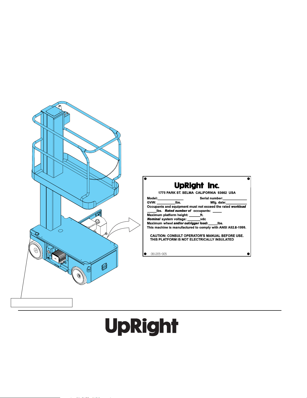
When contacting UpRight for service or parts information, be sure to include the MODEL and SERIAL NUMBERS
from the equipment nameplate. Should the nameplate be missing, the SERIAL NUMBER is also stamped on top of the
chassis above the front axle pivot.
Stamped Serial Number
UpRight, Inc.
801 South Pine Street
Madera, California 93637
TEL: 559-662-3900
FAX: 559-673-6184
PA RTS: 1-888-UR-PART S
PARTS FAX: 1-800-669-9884
Call Toll Free in U.S.A.
1-800-926-LIFT
UpRight
Unit S1, Park West Industrial Park
Friel Avenue
Nangor Road
Dublin 12, Ireland
TEL: +353 1 620 9300
FAX: +353 1 620 9301
Page 3
PERATOR
O
M
ANUAL
WARNING
All personnel shall carefully read, understand and follow all safety rules, operating instructions,
and the Scaffold Industry Association’s MANUAL OF RESPONSIBILITIES of ANSI A92.6-1999
before performing maintenance on or operating any UpRight Aerial Work Platform.
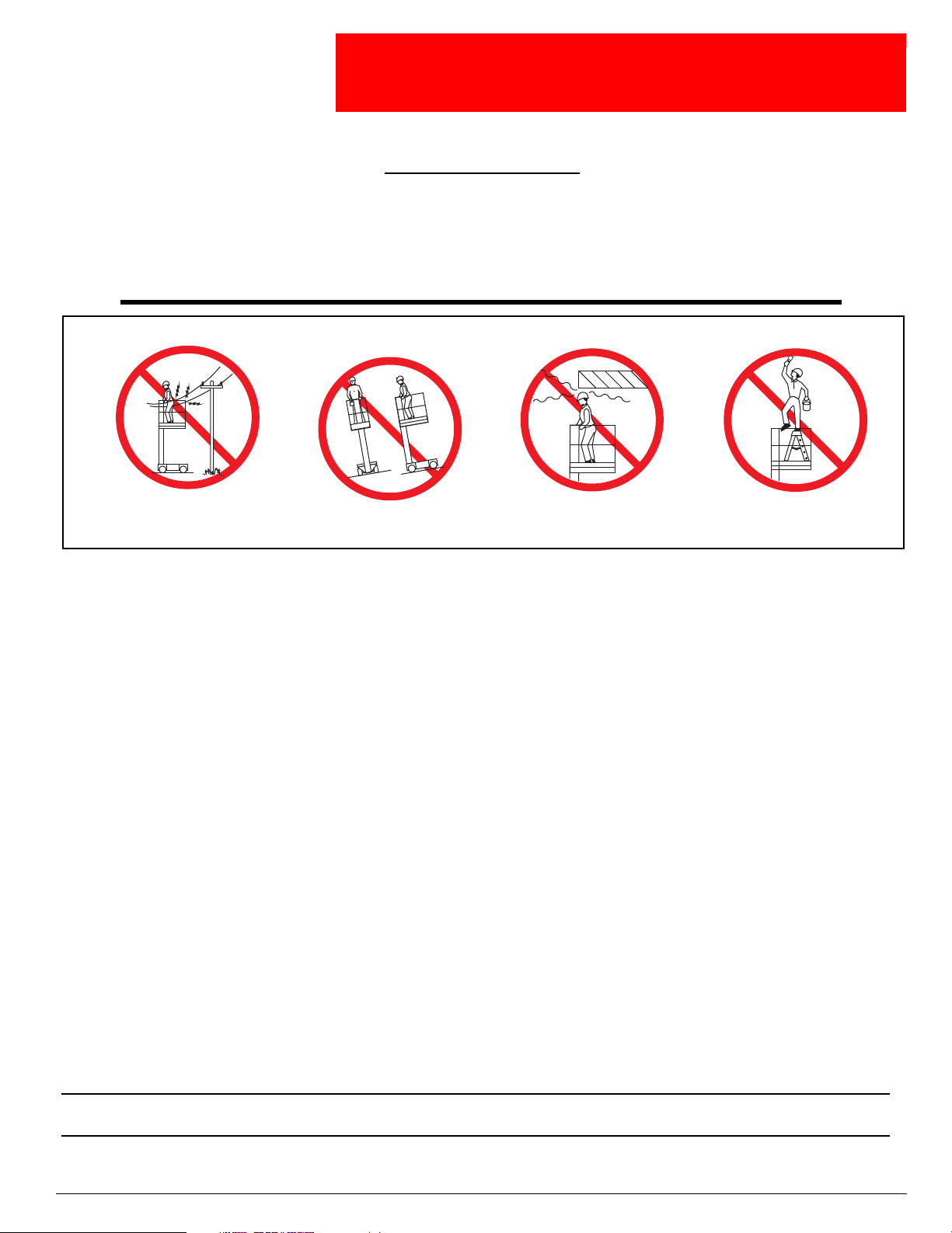
Safety Rules
Safety Rules
Safety RulesSafety Rules
Electrocution Hazard
Electrocution Hazard Tip Over Hazard
Electrocution HazardElectrocution Hazard
Tip Over Hazard Collision Hazard
Tip Over HazardTip Over Hazard
Collision Hazard Fall Hazard
Collision HazardCollision Hazard
Fall Hazard
Fall HazardFall Hazard
NEVER operate the machine within ten
(10) feet of power lines.
THIS MACHINE IS NOT INSULATED.
•
NEVER
curbs, or debris.
•
NEVER
•
ALWAYS
•
NEVER
•
NEVER
•
NEVER
•
LOOK
•
DISTRIBUTE
•
NEVER
•
NEVER
•
INSPECT
hoses, loose wire connections, and wheel bolts.
•
NEVER
•
IF ALARM SOUNDS
surface.
•
IN CASE OF EMERGENCY
•
NEVER
•
NEVER
•
NEVER
turer’s written consent.
•
VERIFY
•
NEVER
•
AFTER USE
operate the machine without first surveying the work area for surface hazards such as holes, drop-offs, bumps,
operate the machine if all guardrails are not properly in place and secured with all fasteners properly torqued.
close and secure the entrance after entering the platform.
use ladders or scaffolding on the platform.
exceed the maximum platform load. See “Specifications” on page 16.
attach overhanging loads or increase platform size.
up, down and around for overhead obstructions and electrical conductors.
all platform loads evenly on the platform.
use damaged equipment. (Contact UpRight for instructions. See toll free phone number on inside back cover.)
change operating or safety systems.
the machine thoroughly for cracked welds, loose or missing hardware, hydraulic leaks, damaged cables or
climb down elevating assembly when the platform is elevated.
while the platform is elevated, STOP, carefully lower the platform. Move the machine to a firm, level
perform service on the machine while the platform is elevated without blocking the elevating assembly.
recharge batteries near sparks or open flame; batteries that are being charged emit explosive hydrogen gas.
replace any component or part with anything other than original UpRight replacement parts without the manufac-
that all labels are in place and legible before using.
tow the machine. Transport by truck or trailer only.
, secure the machine against unauthorized use by turning the Chassis Key Switch off and removing the key.
NEVER operate or drive with the
platform elevated unless on firm, level
push the Emergency Stop Switch to cut power to all machine functions.
surface.
NEVER position the machine without
first checking for overhead obstructions
or other hazards.
NEVER climb, stand or sit on the
platform guardrails or midrail.
California Proposition 65 Warning
Battery Posts, terminals and related accessories contain lead compounds, chemicals known to the State of
California to cause cancer and reproductive harm. Wash hands after handling.
107098-002 TM12 - Operator Manual Page 1
Page 4

C
ONTENTS
Introduction. . . . . . . . . . . . . . . . . . . . . . . . . . . . . . . . . . . . . . . . . . . . . . . . . . . . . . . . . . . . . . . . . . . . . . . . . .3
General Description . . . . . . . . . . . . . . . . . . . . . . . . . . . . . . . . . . . . . . . . . . . . . . . . . . . . . . . . . . . . . . . . . . .3
Controls and Indicators . . . . . . . . . . . . . . . . . . . . . . . . . . . . . . . . . . . . . . . . . . . . . . . . . . . . . . . . . . . . . . . .4
Pre-Operation Safety Inspection . . . . . . . . . . . . . . . . . . . . . . . . . . . . . . . . . . . . . . . . . . . . . . . . . . . . . . . . .4
System Function Inspection . . . . . . . . . . . . . . . . . . . . . . . . . . . . . . . . . . . . . . . . . . . . . . . . . . . . . . . . . . . .5
Operation. . . . . . . . . . . . . . . . . . . . . . . . . . . . . . . . . . . . . . . . . . . . . . . . . . . . . . . . . . . . . . . . . . . . . . . . . . . .6
Travel With Platform Lowered . . . . . . . . . . . . . . . . . . . . . . . . . . . . . . . . . . . . . . . . . . . . . . . . . . . . . . . . . . . . . . . . . . 6
Steering . . . . . . . . . . . . . . . . . . . . . . . . . . . . . . . . . . . . . . . . . . . . . . . . . . . . . . . . . . . . . . . . . . . . . . . . . . . . . . . . . . . 6
Elevating The Platform . . . . . . . . . . . . . . . . . . . . . . . . . . . . . . . . . . . . . . . . . . . . . . . . . . . . . . . . . . . . . . . . . . . . . . . 6
Travel With The Platform Elevated . . . . . . . . . . . . . . . . . . . . . . . . . . . . . . . . . . . . . . . . . . . . . . . . . . . . . . . . . . . . . . 6
Lowering The Platform . . . . . . . . . . . . . . . . . . . . . . . . . . . . . . . . . . . . . . . . . . . . . . . . . . . . . . . . . . . . . . . . . . . . . . . 6
Emergency Lowering. . . . . . . . . . . . . . . . . . . . . . . . . . . . . . . . . . . . . . . . . . . . . . . . . . . . . . . . . . . . . . . . . . . . . . . . . 7
Parking Brake Release . . . . . . . . . . . . . . . . . . . . . . . . . . . . . . . . . . . . . . . . . . . . . . . . . . . . . . . . . . . . . . . . . . . . . . . 7
After Use Each Day. . . . . . . . . . . . . . . . . . . . . . . . . . . . . . . . . . . . . . . . . . . . . . . . . . . . . . . . . . . . . . . . . . . . . . . . . . 7
Transporting the Machine . . . . . . . . . . . . . . . . . . . . . . . . . . . . . . . . . . . . . . . . . . . . . . . . . . . . . . . . . . . . . .8
By Crane . . . . . . . . . . . . . . . . . . . . . . . . . . . . . . . . . . . . . . . . . . . . . . . . . . . . . . . . . . . . . . . . . . . . . . . . . . . . . . . . . . 8
By Forklift . . . . . . . . . . . . . . . . . . . . . . . . . . . . . . . . . . . . . . . . . . . . . . . . . . . . . . . . . . . . . . . . . . . . . . . . . . . . . . . . . 8
By Truck . . . . . . . . . . . . . . . . . . . . . . . . . . . . . . . . . . . . . . . . . . . . . . . . . . . . . . . . . . . . . . . . . . . . . . . . . . . . . . . . . . 8
Maintenance . . . . . . . . . . . . . . . . . . . . . . . . . . . . . . . . . . . . . . . . . . . . . . . . . . . . . . . . . . . . . . . . . . . . . . . . .9
Blocking the Elevating Assembly . . . . . . . . . . . . . . . . . . . . . . . . . . . . . . . . . . . . . . . . . . . . . . . . . . . . . . . . . . . . . . . 9
Installation . . . . . . . . . . . . . . . . . . . . . . . . . . . . . . . . . . . . . . . . . . . . . . . . . . . . . . . . . . . . . . . . . . . . . . . . . . . . . 9
Removal . . . . . . . . . . . . . . . . . . . . . . . . . . . . . . . . . . . . . . . . . . . . . . . . . . . . . . . . . . . . . . . . . . . . . . . . . . . . . . . 9
Hydraulic Fluid. . . . . . . . . . . . . . . . . . . . . . . . . . . . . . . . . . . . . . . . . . . . . . . . . . . . . . . . . . . . . . . . . . . . . . . . . . . . . . 9
Check Hydraulic Fluid . . . . . . . . . . . . . . . . . . . . . . . . . . . . . . . . . . . . . . . . . . . . . . . . . . . . . . . . . . . . . . . . . . . . 9
Battery Maintenance . . . . . . . . . . . . . . . . . . . . . . . . . . . . . . . . . . . . . . . . . . . . . . . . . . . . . . . . . . . . . . . . . . . . . . . . 10
Battery Charging . . . . . . . . . . . . . . . . . . . . . . . . . . . . . . . . . . . . . . . . . . . . . . . . . . . . . . . . . . . . . . . . . . . . . . . . . . . 11
Daily Inspection and Maintenance Schedule . . . . . . . . . . . . . . . . . . . . . . . . . . . . . . . . . . . . . . . . . . . . . .12
Daily Preventative Maintenance Checklist . . . . . . . . . . . . . . . . . . . . . . . . . . . . . . . . . . . . . . . . . . . . . . . .13
Labels . . . . . . . . . . . . . . . . . . . . . . . . . . . . . . . . . . . . . . . . . . . . . . . . . . . . . . . . . . . . . . . . . . . . . . . . . . . . .14
Specifications . . . . . . . . . . . . . . . . . . . . . . . . . . . . . . . . . . . . . . . . . . . . . . . . . . . . . . . . . . . . . . . . . . . . . . .16
Page 2 107098-002 TM12 - Operator Manual
Page 5
I
WARNING
!
!
NTRODUCTION
G
ENERAL
Introduction
This manual covers the TM12 Aerial Work Platform. This manual must be stored on the machine at all
times.
Read, understand and follow all safety rules and operating instructions before attempting to operate the
machine.
D
ESCRIPTION
DO NOT
are not properly in place and secured with
all fasteners properly torqued
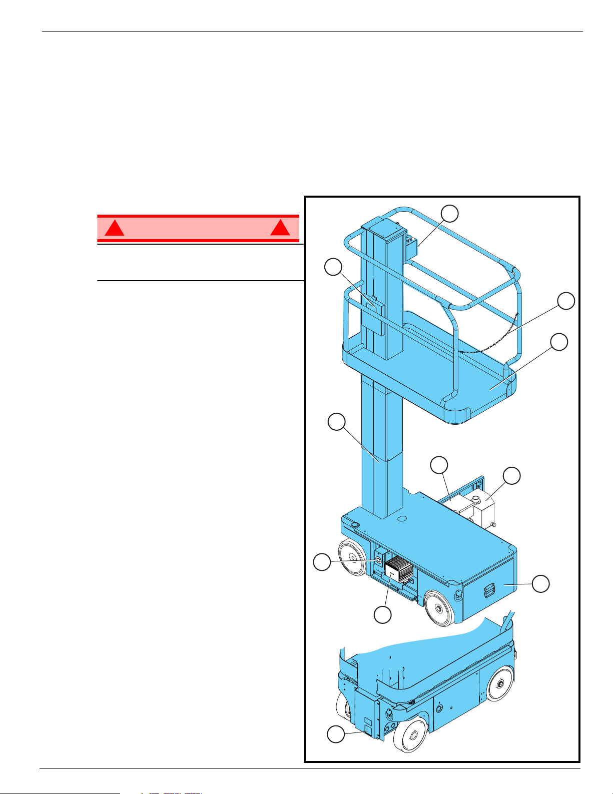
10. Battery Charger
11. Charger Outlet Plug
use the machine
1. Platform
2. Entry Chain
3. Elevating Mast
4. Platform Controls
5. Manual Case
6. Electrical Box
7. Hydraulic Reservoir
8. Battery Tray
9. Emergency Down Valve Knob
if all guardrails
.
Figure 1:
TM12 Series
4
5
2
1
3
6
7
11
10
9
107098-002 TM12 - Operator Manual Page 3
8
Page 6
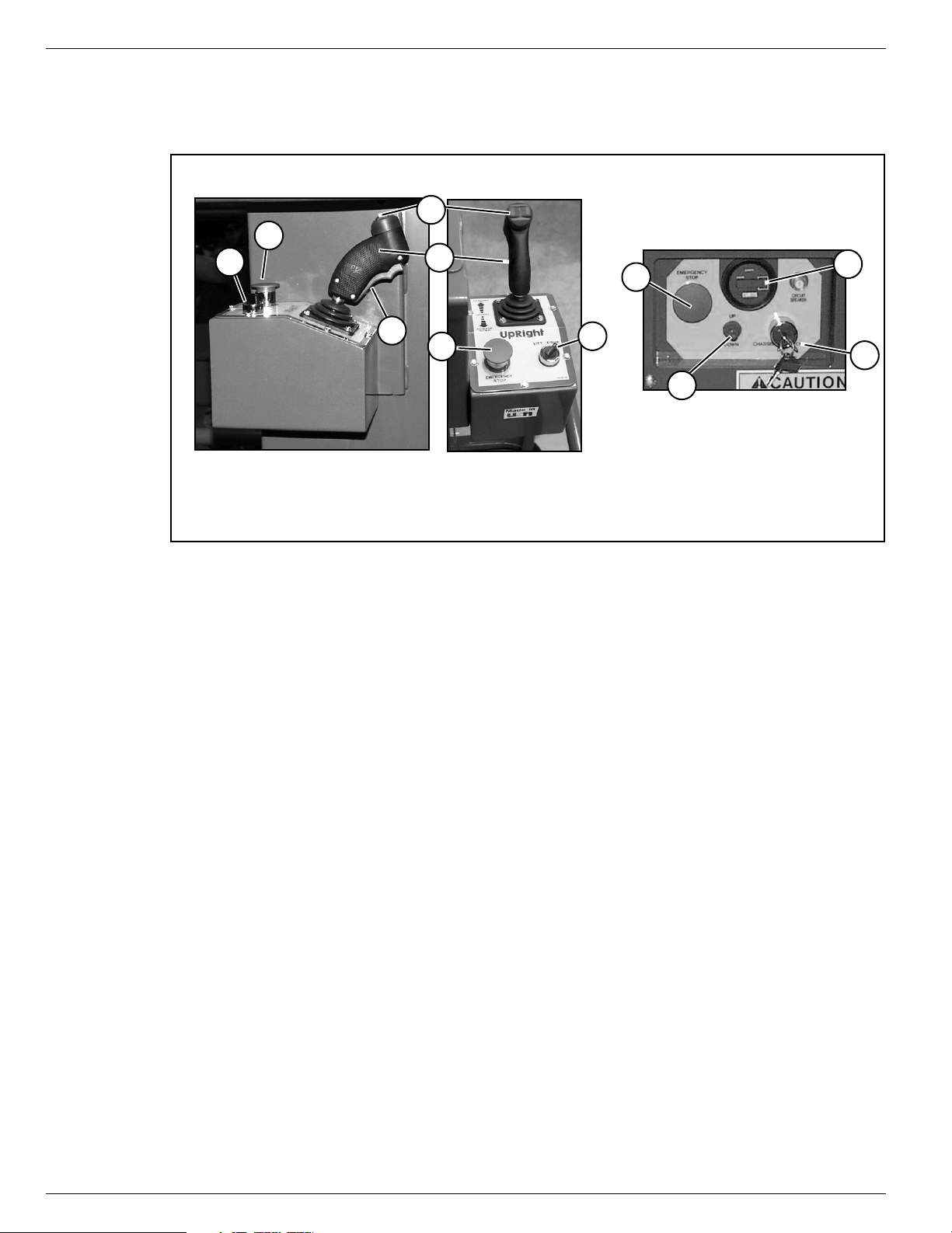
Controls and Indicators
Platform Controller
5
2
8
6
7
9
1
Chassis Controller (Right Side)
4
3
5
2
1. Interlock Switch
2. Platform Emergency Stop Switch
3. Control Handle
4. Steering Switch
5. Lift/Drive Switch
6. Chassis Emergency Stop Switch
7. Chassis Up/Down Switch
8. Chassis Key Switch
9. Hour Meter
C
ONTROLS
The operator shall know the location of each control and indicator and have a thorough knowledge of the
function and operation of each before attempting to operate the unit.
AND
I
NDICATORS
Figure 2:
Controls and Indicators
P
RE
-O
PERATION
NOTE:
Carefully read, understand and follow all safety rules, operating instructions, labels,
Industry Association’s MANUAL OF RESPONSIBILITIES of ANSI A92.6-1999
steps each day before use.
1. Open the chassis door and inspect for damage, fluid leaks or missing parts.
2. Check the level of the hydraulic fluid with the platform fully lowered. Open the chassis door and remove
the reservoir cap, fluid should be visible on the dipstick. Add recommended hydraulic fluid if necessary.
See “Specifications” on page 16.
3. Check that the fluid level in the batteries is correct. See “Battery Maintenance” on page 10.
4. Verify that the batteries are charged.
5. Check that the A.C. extension cord has been disconnected from the chassis outlet.
6. Check that all guardrails are properly in place and secured with all fasteners properly torqued.
7. Inspect the machine thoroughly for cracked welds, loose or missing hardware, hydraulic leaks, damaged cables or hoses, loose wire connections, and wheel bolts.
S
AFETY
I
NSPECTION
and the Scaffold
. Perform the following
Page 4 107098-002 TM12 - Operator Manual
Page 7

S
WARNING
!
!
YSTEM
System Function Inspection
F
UNCTION
Refer to Figure 1 and Figure 2 for the locations of various controls and indicators.
I
NSPECTION
STAND CLEAR
Before operating the machine, survey the work area for surface hazards such as holes, drop-offs, bumps,
curbs, or debris.
LOOK up, down and around for overhead obstructions and electrical conductors.
Protect the control cable from possible damage while performing checks.
1. Move the machine, if necessary, to an unobstructed area to allow for full elevation.
2. Turn the Chassis and Platform Emergency Stop Switches ON by pulling the buttons out.
3. Check Level Sensor operation:
a. Open the door.
b. Push and hold the sensor off of level.
c. Turn and hold the Chassis Key Switch to
CHASSIS and push the Chassis Up/Down
Switch to the UP position.
• The alarm should sound, and the platform should not lift.
d. Close and latch the door.
4. Turn and hold the Chassis Key Switch to
CHASSIS and push the Chassis Up/Down
Switch to the UP position and fully elevate the
platform.
5. Visually inspect the mast assembly for damage or erratic operation. Check for missing or loose parts.
6. Verify that the depression mechanism supports have rotated into position under the machine.
7. Partially lower the platform by pushing the Chassis Up/Down Switch to DOWN, and check the operation
of the audible lowering alarm.
8. Check the Emergency Down Valve for proper operation (see Figure 4):
a. Open the valve by pulling the knob out.
b. Once the platform is fully lowered, close the valve by releasing the knob.
9. Push the Chassis Emergency Stop Switch in to the OFF position. All machine functions should be disabled. Pull the Chassis Emergency Stop Switch out to resume.
10. Turn the Chassis Key Switch to DECK.
11. Check that the route is clear of persons, obstructions, holes and drop-offs, is level and capable of supporting the wheel loads.
12. After mounting the platform, properly close and secure the entrance.
13. Position the Lift/Drive Switch to DRIVE.
14. Check for speed and directional control.
• While engaging the Interlock Switch, slowly position the Control Handle to FORWARD then
REVERSE. The farther you push or pull the Control Handle from center the faster the machine will
travel.
15. Push the Steering Switch RIGHT then LEFT to check for steering control.
16. Turn the Lift/Drive switch to LIFT to check platform lift controls.
• While engaging the Interlock Switch, move the Control Handle to UP to raise the platform.
• While engaging the Interlock Switch, move the Control Handle to DOWN to lower the platform. The
platform should descend and the audible lowering alarm should sound.
17. Push the Platform Emergency Stop Switch in to the OFF position. All machine functions should be disabled. Pull the Platform Emergency Stop Switch out to resume.
of the machine while performing the following checks.
Level Sensor
Figure 3:
Level Sensor Location
107098-002 TM12 - Operator Manual Page 5
Page 8

Operation
O
PERATION
Before operating the machine, ensure that the Pre-Operation Safety Inspection and System Function
Inspection has been completed and that any deficiencies have been corrected.
aged or malfunctioning machine.
T
RAVEL
1. Check that the route is clear of surface hazards such as holes, drop-offs, bumps, curbs, or debris.
2. Check that the route is level, and is capable of supporting the wheel loads.
3. Verify that the Chassis Key Switch is turned to DECK and the Chassis Emergency Stop Switch is ON,
(pull button out).
4. After mounting the platform, properly close entrance.
5. Check clearances above, below and to the sides of the machine.
6. Pull the Platform Controls Emergency Stop switch up to the ON position.
7. Position the Lift/Drive Switch to DRIVE.
8. While depressing the Interlock Switch, slowly push or pull the Control Handle to FORWARD or
REVERSE position to travel in the desired direction. The farther you push or pull the Control Handle
from center the faster the machine will travel.
S
TEERING
W
ITH
P
LATFORM
The operator must be thoroughly trained on this machine.
L
OWERED
Never operate a dam-
NOTE:
Steering is not self-centering. Wheels must be returned to straight ahead position by operating the Steering
Switch.
1. Position the Lift/Drive Switch to DRIVE.
2. While depressing the Interlock Switch, push the Steering Switch to RIGHT or LEFT to turn the wheels
in the desired direction. Observe the tires while maneuvering the machine to ensure proper direction.
E
LEVATING
1. Position the Lift/Drive Switch to LIFT.
2. While depressing the Interlock Switch, push Control Handle forward to UP, the farther you push the
Control Handle the faster the Platform will elevate.
3. If the machine is not level the Tilt Alarm will sound and the machine will not lift or drive. If the Tilt alarm
sounds the platform must be lowered and the machine moved to a firm, level surface before attempting
to elevate the platform.
T
RAVEL
NOTE:
The machine will travel at reduced speed when the platform is elevated.
1. Check that the route is clear of surface hazards such as holes, drop-offs, bumps, curbs, or debris.
2. Check that the route is level, and is capable of supporting the wheel loads.
3. Check clearances above, below and to the sides of the platform.
4. Position the Lift/Drive Switch to the DRIVE position.
5. While depressing the Interlock Switch, push Control Handle to FORWARD or REVERSE for desired
direction of travel.
6. If the machine is not level the Tilt Alarm will sound and the machine will not lift or drive. If the Tilt alarm
sounds the platform must be lowered and the machine moved to a level location before attempting to
elevate the platform.
W
T
ITH
HE
T
P
LATFORM
HE
P
LATFORM
E
LEVATED
L
OWERING
1. Position the Lift/Drive Switch to LIFT.
2. While depressing the Interlock Switch, pull back on the Control Handle.
Page 6 107098-002 TM12 - Operator Manual
T
HE
P
LATFORM
Page 9

E
WARNING
!
!
WARNING
!
!
Emergency Down Valve Knob
MERGENCY
If the platform should fail to lower, NEVER climb down the elevating assembly.
Stand clear of the elevating assembly while operating the Emergency Down Valve Knob.
L
OWERING
Operation
Figure 4:
Ask a person on the ground to open the Emergency
Down Valve to lower the platform. The Emergency Down
Valve Knob is located at the front of the chassis.
1. Open the Emergency Down Valve by pulling the knob
out.
2. To close, release the knob.
NOTE:
The platform will not elevate if the Emergency Down Valve
is open.
P
ARKING
Perform the following procedure only when the machine will not operate under its own power and it is necessary to move the machine, or when winching onto a trailer to transport.
1. Remove the spring compression nut so the
spring is loose and the brake bars are away
from the tires.
2. The machine will now roll when pushed or
pulled.
B
RAKE
R
ELEASE
Emergency Down Valve Knob
Figure 5:
Parking Brake Release
Spring
Compression
Nut
After moving the machine and before normal operation:
1. Replace the spring compression nut and
tighten until the spring measures 22,2 cm –
22,9 cm (
the brake bars have fully engaged the tires
before the machine is operated.
Never tow faster than 0,3 m/sec. (
Never operate the machine with the parking brakes released. Serious injury or damage could result.
A
FTER
1. Ensure that the platform is fully lowered.
2. Park the machine on a firm level surface, preferably under cover, secure against vandals, children and
unauthorized operation.
3. Turn the Chassis Key Switch to OFF and remove the key to prevent unauthorized operation.
8¾ in. – 9 in.
U
SE
E
) in length, verify that
1 ft./sec.
ACH
D
AY
).
8¾ in. – 9 in.
107098-002 TM12 - Operator Manual Page 7
Page 10

Transporting the Machine
DANGER
! !
DANGER
! !
CAUTION
Forklift From
Side
Typical Tie Down/Lift Points
(D-Rings)
T
RANSPORTING
THE
M
ACHINE
BY C
See specifications for weight of machine and be certain that crane is of adequate capacity to lift the
machine.
BY F
Forklifting is for transport only.
See specifications for weight of machine and be certain that forklift is of adequate capacity to lift the
machine.
RANE
Secure the straps to chassis lifting/tie down points only.
ORKLIFT
Forklift from the side by lifting under the chassis.
Figure 6:
Transporting the Machine
BY T
1. Maneuver the machine into transport position and
2. Secure the machine to the transport vehicle with
Overtightening chains or straps attached to the Tie
Down lugs may result in damage to the machine
RUCK
chock wheels.
chains or straps of adequate load capacity
attached to the chassis lifting/tie down points.
Page 8 107098-002 TM12 - Operator Manual
Page 11

M
WARNING
!
!
1
2
3
1 Wood Block 50 cm (
18 in.
) long
2. Number Two Mast
3. Number One Mast
AINTENANCE
Maintenance
Never perform service while the platform is elevated without first blocking the elevating assembly.
DO NOT stand in the elevating assembly area while deploying or storing the brace.
B
LOCKING
SSEMBLY
A
I
NSTALLATION
1. Park the machine on firm level ground.
2. Verify that both Emergency Stop Switches are ON.
3. Turn and hold the Chassis Key Switch to CHASSIS.
4. Position the Chassis Up/Down Switch to UP and elevate the platform approximately 1,2 m (
5. Place a solid 2 x 4 wood block, approximately 50 cm
(
18 in.
chassis just behind the mast assembly and against
the number one mast.
6. Move the Chassis Lift Switch to the DOWN position
and gradually lower the work platform until the number two mast is supported by the block.
R
EMOVAL
1. Push the Chassis Up/Down Switch to the UP position and gradually raise platform until the wood block
can be removed.
2. Remove the block.
3. Push the Chassis Up/Down Switch to the DOWN
position and completely lower the platform.
THE
) long, between the number two mast and
E
LEVATING
4 ft.
).
Figure 7:
Supporting the Elevating Assembly
107098-002 TM12 - Operator Manual Page 9
H
YDRAULIC
The hydraulic fluid reservoir is located in the chassis door.
NOTE:
Never add fluid if the platform is elevated.
C
HECK HYDRAULIC
1. Make sure that the platform is fully lowered.
2. Open the chassis door.
3. Remove the filler cap from the hydraulic fluid reservoir.
4. Check the fluid level on the dipstick on the filler cap.
5. Add the appropriate fluid to bring the level to the FULL
mark. See “Specifications” on page 16.
F
LUID
F
LUID
Figure 8:
Hydraulic Fluid Reservoir and Dipstick
Page 12

Maintenance
WARNING
!
!
B
ATTERY
Hazard of explosive gas mixture. Keep sparks, flame,
and smoking material away from batteries.
Always wear safety glasses when working near
batteries.
Battery fluid is highly corrosive. Thoroughly rinse away
any spilled fluid with clean water.
Always replace batteries with UpRight batteries or
manufacturer approved replacements weighing 26,3 kg
(
58 lbs.
) each.
M
AINTENANCE
Figure 9:
Access to Batteries
• Check the battery fluid level daily, especially if the machine is being used in a warm, dry climate.
• If electrolyte level is lower than 10 mm
tap water with high mineral content, as it will shorten battery life.
• Inspect the battery regularly for signs of cracks in the case, electrolyte leakage and corrosion of the
terminals.
• Inspect cables regularly for worn spots or breaks in the insulation and for broken cable terminals.
• Keep the terminals and tops of the batteries clean.
• Refer to the Service Manual to extend battery life and for complete service instructions.
3
) above the plates add distilled water only. DO NOT use
(
/
in.
8
Page 10 107098-002 TM12 - Operator Manual
Page 13

B
WARNING
!
!
Battery
Charge
Indicator
ATTERY
C
HARGING
Charge the batteries at the end of each work shift or
sooner if the batteries have been discharged.
Charge the batteries in a well ventilated area.
Do not charge the batteries when the machine is near a
source of sparks or flames.
Permanent damage to the batteries will result if the
batteries are not immediately recharged after discharging.
Never leave the battery charger operating for more than two days.
Never disconnect the cables from the batteries when the charger is operating.
Keep the charger dry.
Figure 10:
Maintenance
Battery Charge Indicator
1. Check the battery fluid level. If the battery fluid level is lower than 10 mm
3
) above the plates add
(
/
in.
8
distilled water only.
2. Connect an extension cord (1,5 mm
[
²
12 gauge
] minimum conductor diameter; 15 m [
50 ft.
] maximum
length) to the charger plug located through a cutout at the left side of the chassis.
3. The charger turns on automatically after a short delay. There are three LED’s to indicate the state of
charge cycle.
• The first LED will blink until the batteries reach 50% state of charge, and then it will stop blinking and
stay ON.
• The second LED will blink until the batteries reach 75% state of charge, and then it will stop blinking
and stay ON.
• The third LED will blink until the batteries reach 100% state of charge, and then it will stop blinking and
stay ON.
• When the batteries are fully charged, all three LED’s will stay ON. The battery charger will automatically turn off a short time after the batteries reach full charge.
NOTE:
The battery charger circuit must be used with a GFI (Ground Fault Interrupt) outlet.
NOTE:
DO NOT operate the machine while the charger is plugged in.
107098-002 TM12 - Operator Manual Page 11
Page 14

Daily Inspection and Maintenance Schedule
WARNING
!
!
D
AILY
I
NSPECTION
The Complete Inspection consists of periodic visual and operational checks, along with periodic minor
adjustments that assure proper performance. Daily inspection will prevent abnormal wear and prolong the
life of all systems. Perform the inspection and maintenance items daily. Inspection and maintenance shall
be performed by personnel who are trained and familiar with mechanical and electrical procedures.
Before performing preventative maintenance, familiarize yourself with the operation of the machine.
Always block the elevating assembly whenever it is necessary to perform maintenance while the
platform is elevated.
The daily preventative maintenance checklist has been designed for machine service and maintenance.
Please photocopy the Daily Preventative Maintenance Checklist and use the checklist when inspecting
the machine.
AND
M
AINTENANCE
S
CHEDULE
Page 12 107098-002 TM12 - Operator Manual
Page 15

D
AILY
P
REVENTATIVE
M
AINTENANCE
C
HECKLIST
Daily Preventative Maintenance Checklist
M
AINTENANCE
= Yes/Acceptable
Y
= No/Not Acceptable
N
= Repaired/Acceptable
R
COMPONENT INSPECTION OR SERVICES Y N R
Battery
Chassis
Control Cable
Controller Check switch operation.
Drive Motors Check for operation and leaks.
Elevating Assembly
Emergency Hydraulic
System
T
ABLE KEY
Check electrolyte level.
Check battery cable condition.
Charge batteries
Check charger condition and operation
Check hoses for pinch or rubbing points.
Check welds for cracks.
Check the exterior of the cable for pinching,
binding or wear.
Inspect for external damage, dents, loose rivets
or cracks.
Operate the emergency down valve and check
for serviceability.
P
REVENTATIVE
M
AINTENANCE
R
EPORT
Date: _______________________________________
Owner: ______________________________________
Model No: ___________________________________
Serial No:____________________________________
Serviced By: _________________________________
COMPONENT INSPECTION OR SERVICES Y N R
Entire Unit
Hydraulic Fluid Check fluid level.
Hydraulic Pump Check for hose fitting leaks.
Hydraulic System Check for leaks.
Labels
Lift Cylinder Check for leaks
Platform Deck and
Rails
Tires Check for damage.
Wheels Check for loose components
Perform pre-operation inspection.
Check for and repair collision damage.
Check for peeling, missing, or unreadable
labels & replace.
Check welds for cracks.
Check condition of deck.
Check entry way closure.
107098-002 TM12 - Operator Manual Page 13
Page 16

Labels
L
ABELS
These labels shall be present and in good condition before operating the machine. Be sure to read, understand and follow these labels when operating the machine.
HYDRAULIC FLUID
1 060197-000
2 066552-000
3 061205-005
BATTERY
MAINTAIN BATTERY FLUID
AT RECOMMENDED LEVEL
5 005221-000
060197-000
10 101250-000
23 066555-000
!
WARNING
CRUSHING HAZARD
KEEP CLEAR OF
13 010076-001
EMERGENCY
STOP
UP
DOWN
CHASSIS
OFF
CIRCUIT
BREAKER
DECK
24 066568-000
PLATFORM
LOWER PLATFORM
COMPLETELY BEFORE
SERVICING MACHINE
15 065568-001
!
DANGER
TIP-OVER HAZARD
BATTERIES ACT AS COUNTERWEIGHT
EACH REPLACEMENT BATTERY SHALL WEIGH
60 LBS OR MORE
25 066556-000
6 005223-005
7 .066554-000
FORWARD
UP
NEUTRAL
DOWN
REVERSE
UpRight
CUTOUT
LIFT DRIVE
CUTOUT
19 062562-001
!
DANGER
Failure to read, understand,
and obey the following safety
rules will cause death or
serious injury.
TIP-OVER HAZARDS
DO NOT elevate or drive elevated on
slopes or soft ground.
DO NOT drive into holes or over
drop offs
ELECTROCUTION HAZARD
DO NOT operate within ten feet of power
lines. THIS MACHINE IS NOT INSULATED.
Look up, down and around for electrical
wires.
FALL HAZARD
DO NOT climb on guardrail.
Make sure guardrails are fastened securely
Secure gate or chain across enterance.
DO NOT use ladders or scaffolding on platform
DO NOT climb down mast.
20 066550-001
21 014222-003-99
BATTERY
CHARGER
26 066522-000
27 101252-000
28 066556-001
EMERGENCY
STOP
8 107050-000
22 061220-002
29 107051-000
Page 14 107098-002 TM12 - Operator Manual
Page 17

Labels
Figure 11:
Safety Labels Locations
107098-002 TM12 - Operator Manual Page 15
Page 18

Specifications
S
PECIFICATIONS
Specifications subject to change without notice. Refer to the Service Manual for service and repair information. Refer to the Parts Manual for illustrated parts breakdown. Hot weather or heavy use may reduce
performance. Meets or exceeds all applicable national safety requirements
ITEM TM12
Platform Size 73,7 cm x 1,04 m (
Maximum Platform Capacity 227 kg (
Maximum Number of Occupants 2 People
Height
Working Height
Maximum Platform Height
Minimum Platform Height
Dimensions
Weight
Overall Width
Overall Height (Lowered)
Overall Length
Drive Speed
Platform Lowered
Platform Raised
Energy Source 24V battery pack
776 kg (
1,36 m (
3,65 km/h (
0,87 km/h (
5,83 m (
3,66 m (
48,3 cm (
76 cm (
165 cm (
29 in. x 41 in.
500 lbs.
19 ft.
12 ft.
19 in.
1710 lbs.
30 in.
65 in.
53.5 in.
2.27 mph
0.54 mph
Four 220 ampere hour, 6 Volt batteries, min. wt. 26,3 kg (58 lbs.) each
4 HP DC electric motor
System Voltage 24 VDC
Battery Charger 20 AMP, 220 VAC 50Hz
Battery Duty Cycle 25% for 8 Hours
Hydraulic Reservoir Capacity 7,2 L (
Maximum Hydraulic System Pressure 165 bar (
Hydraulic Fluid
Normal above 0° C [32° F]
Low Temp. below 0° C [32° F]
below -17° C [0° F]
Lift System One Single Stage Lift Cylinder
Drive Control Proportional
Control System Proportional Control Handle with Interlock, Selector Switch,
Horizontal Drive Dual Front Wheel
Tires 30,5 cm (
Parking Brakes Dual, Spring Applied, Hydraulic Release
Turning Radius (Inside) 37 cm (
Maximum Gradeability 14º (
Wheel Base 97,8 cm (
Guardrails 1,10 m (
Toeboard 152 mm (
Red Mushroom Emergency Stop Switches
12 in.
1.9 gal
2400 psi
ISO #46
ISO #32
ISO #15
) diameter solid rubber, Non-marking
14.5 in.
)
25%
38.5 in.
43 in.
6 in.
)
)
)
)
)
)
)
)
)
)
)
)
)
)
)
)
)
*Specifications are subject to change without notice. Hot weather or heavy use may affect performance.
Refer to the Parts Manual and the Service Manual for complete parts and service information.
The TM12 meets or exceeds all applicable requirements of OSHA and ANSI A92.6-1999.
Page 16 107098-002 TM12 - Operator Manual
Page 19

Call Toll Free in U.S.A.
1-800-926-LIFT
Page 20

USA
TEL: (1) 800-926-5438 or (1) 559-662-3900
FAX: (1) 559-673-6184
Parts FAX: (1) 800-669-9884
801 South Pine Street
Madera, California 93637
http://www.upright.com
E
UROPE
TEL: +353 1 620 9300
FAX: +353 1 620 9301
Unit S1, Park West Industrial Park
Friel Avenue
Nangor Road
Dublin 12, Ireland
L
OCAL DISTRIBUTOR
:
P/N 107098-002
07-02
 Loading...