

Page 1
TM12
Operator Manual
This first section of the Operator manual is the English language version.
Manuel Utilisateur
èLa troisième section de ce manuel est la version en langue Française.
Manual del Usuario
El apartado cuarto de este manual del usuario corresponde a la versión en Españo.
(EN) Manual part number 505114-101 for serial numbers 51941 to current.
(FR) Manuel Pièce numéro 505114-101 pour numéro série 51941 jusqu'au
numéro courant.
(ES) El número de referencia para el manual es el 505114-101 para la
números de serie del 51941 hasta el actual.
Page 2

Page 3
Serial Numbers 51941 – Current
Page 4
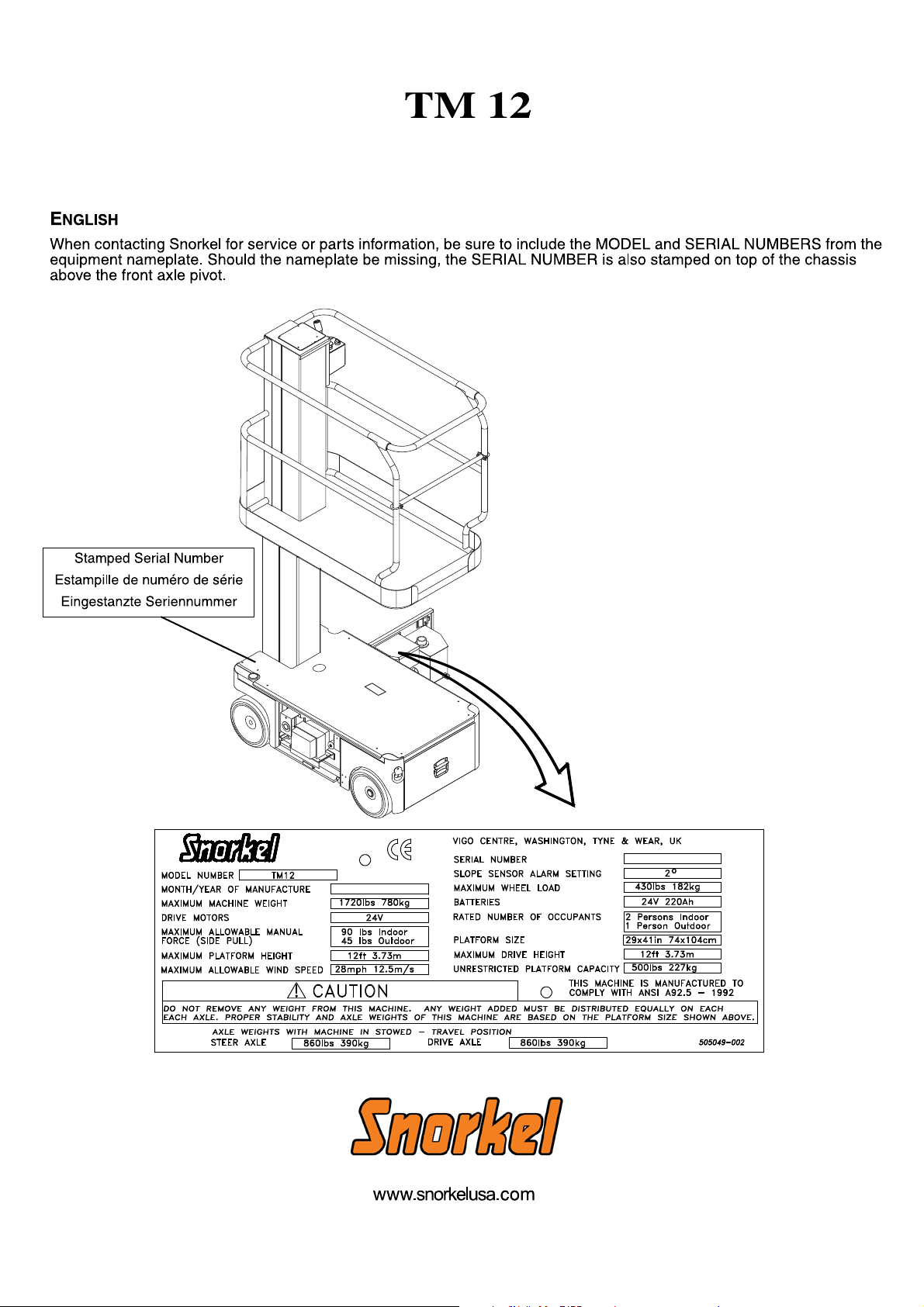
OPERATION MANUAL
C
WARNING
All personnel shall carefu ll y read, under stand and f ollow a ll saf ety rules and operating inst ructions
before operating or performing maintenance on any Snorkel International aerial work platform.
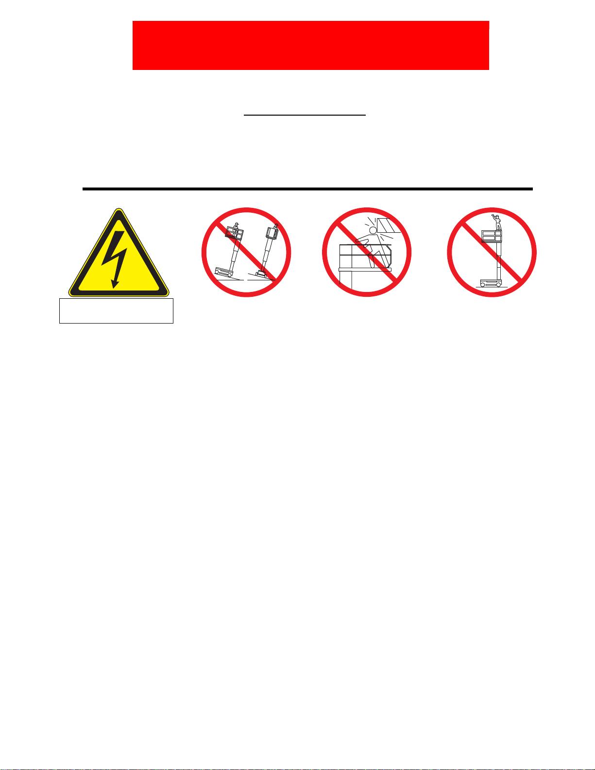
Safety Rules
Electrocution Hazard Tip Over Hazard
THIS MACHINE IS NOT
INSULATED!
USE OF THE AERIAL WORK PLATFORM: This aerial work platform is intended to lift persons and his tools as well as the material used
for the job. It is designed for repair and assembly jobs and assignments at overhead workplaces (ceilings, cranes, roof structures, buildings etc.). All other uses of the aerial work platform are prohibited!
THIS AERIAL WORK PLATFORM IS NOT INSULATED! For this reason it is imperative to keep a safe distance from live parts of electrical equipment!
Exceeding the specified permissible maximum load is prohibited! See “Platform Capacity” on page 4 for details.
The use and operation of the aerial work platform as a lifting tool or a crane is prohibited!
NEVER exceed the manual force allowed for this machine. See “Manual Force” on page 4 for details.
DISTRIBUTE all platform loads evenly on the platform.
NEVER operate the machine without first surveying the work area for surface hazards such as holes, drop-offs, bumps, curbs, or debris;
and avoiding them.
OPERATE machine only on surfaces capable of supporting wheel loads.
NEVER operate the machine when wind speeds exceed this machine’s wind rating. See “Beaufort Scale” on page 4 for details.
IN CASE OF EMERGENCY push EMERGENCY STOP switch to deactivate all powered functions.
IF ALARM SOUNDS while platform is elevated, STOP, carefully lower platform. Move machine to a firm, level surface.
Climbing up the railing of the platform, standing on or stepping from the platform onto buildings, steel or prefab concrete structures, etc.,
is prohibited!
Dismantling the entry gate or other railing components is prohibited! Always make certain that the entry gate is closed and securely
locked!
It is prohibited to keep the entry gate in an open position when the platform is raised!
To extend the height or the range by placing of ladders, scaffolds or similar devices on the platform is prohibited!
NEVER perform service on machine while platform is elevated without blocking elevating assembly.
INSPECT the machine thoroughly for cracked welds, loose or missing hardware, hydraulic leaks, loose wire connections, and damaged
cables or hoses before using.
VERIFY that all labels are in place and legible before using.
NEVER use a machine that is damaged, not functioning properly, or has damaged or missing labels.
To bypass any safety equipment is prohibited and presents a danger for the persons on the aerial work platform and in its working range.
NEVER charge batteries near sparks or open flame. Charging batteries emit explosive hydrogen gas.
Modifications to the aerial work platform are prohibited or permissible only at the approval by
AFTER USE, secure the work platform from unauthorized use by turning the keyswitch off and removing key.
NEVER elevate the platf orm or drive
the machine while elevated unless
the machine is on a firm, level
surface.
ollision Hazard Fall Hazard
NEVER position the platform
without first checking for overhead
obstructions or other hazards.
Snorkel International.
NEVER climb, stand, or sit on
platform guardrails or midrail.
Page 1 Operation Manual
Page 5

C
ONTENTS
Introduction. . . . . . . . . . . . . . . . . . . . . . . . . . . . . . . . . . . . . . . . . . . . . . . . . . . . . . . . . . . . . . . . . . . . . . . . . .3
General Description . . . . . . . . . . . . . . . . . . . . . . . . . . . . . . . . . . . . . . . . . . . . . . . . . . . . . . . . . . . . . . . . . . .3
Special Limitations. . . . . . . . . . . . . . . . . . . . . . . . . . . . . . . . . . . . . . . . . . . . . . . . . . . . . . . . . . . . . . . . . . . .4
Platform Capacity . . . . . . . . . . . . . . . . . . . . . . . . . . . . . . . . . . . . . . . . . . . . . . . . . . . . . . . . . . . . . . . . . . . . . . . . . . . 4
Manual Force. . . . . . . . . . . . . . . . . . . . . . . . . . . . . . . . . . . . . . . . . . . . . . . . . . . . . . . . . . . . . . . . . . . . . . . . . . . . . . . 4
Beaufort Scale. . . . . . . . . . . . . . . . . . . . . . . . . . . . . . . . . . . . . . . . . . . . . . . . . . . . . . . . . . . . . . . . . . . . . . . . . . . . . . 4
Controls and Indicators . . . . . . . . . . . . . . . . . . . . . . . . . . . . . . . . . . . . . . . . . . . . . . . . . . . . . . . . . . . . . . . .5
Wanring Beacon . . . . . . . . . . . . . . . . . . . . . . . . . . . . . . . . . . . . . . . . . . . . . . . . . . . . . . . . . . . . . . . . . . . . . . . . . . . . 5
Pre-Operation Safety Inspection . . . . . . . . . . . . . . . . . . . . . . . . . . . . . . . . . . . . . . . . . . . . . . . . . . . . . . . . . . . . . . . . 5
System Function Inspection . . . . . . . . . . . . . . . . . . . . . . . . . . . . . . . . . . . . . . . . . . . . . . . . . . . . . . . . . . . .6
Operation. . . . . . . . . . . . . . . . . . . . . . . . . . . . . . . . . . . . . . . . . . . . . . . . . . . . . . . . . . . . . . . . . . . . . . . . . . . .7
Travel With Platform Lowered . . . . . . . . . . . . . . . . . . . . . . . . . . . . . . . . . . . . . . . . . . . . . . . . . . . . . . . . . . . . . . . . . . 7
Steering . . . . . . . . . . . . . . . . . . . . . . . . . . . . . . . . . . . . . . . . . . . . . . . . . . . . . . . . . . . . . . . . . . . . . . . . . . . . . . . . . . . 7
Elevating Platform . . . . . . . . . . . . . . . . . . . . . . . . . . . . . . . . . . . . . . . . . . . . . . . . . . . . . . . . . . . . . . . . . . . . . . . . . . . 7
Travel With Platform Elevated. . . . . . . . . . . . . . . . . . . . . . . . . . . . . . . . . . . . . . . . . . . . . . . . . . . . . . . . . . . . . . . . . . 7
Lowering Platform . . . . . . . . . . . . . . . . . . . . . . . . . . . . . . . . . . . . . . . . . . . . . . . . . . . . . . . . . . . . . . . . . . . . . . . . . . . 7
Emergency Lowering. . . . . . . . . . . . . . . . . . . . . . . . . . . . . . . . . . . . . . . . . . . . . . . . . . . . . . . . . . . . . . . . . . . . . . . . . 8
Parking Brake Release . . . . . . . . . . . . . . . . . . . . . . . . . . . . . . . . . . . . . . . . . . . . . . . . . . . . . . . . . . . . . . . . . . . . . . . 8
After Use Each Day. . . . . . . . . . . . . . . . . . . . . . . . . . . . . . . . . . . . . . . . . . . . . . . . . . . . . . . . . . . . . . . . . . . . . . . . . . 8
Transporting the Machine . . . . . . . . . . . . . . . . . . . . . . . . . . . . . . . . . . . . . . . . . . . . . . . . . . . . . . . . . . . . . .9
By Crane . . . . . . . . . . . . . . . . . . . . . . . . . . . . . . . . . . . . . . . . . . . . . . . . . . . . . . . . . . . . . . . . . . . . . . . . . . . . . . . . . . 9
By Forklift. . . . . . . . . . . . . . . . . . . . . . . . . . . . . . . . . . . . . . . . . . . . . . . . . . . . . . . . . . . . . . . . . . . . . . . . . . . . . . . . . . 9
By Truck. . . . . . . . . . . . . . . . . . . . . . . . . . . . . . . . . . . . . . . . . . . . . . . . . . . . . . . . . . . . . . . . . . . . . . . . . . . . . . . . . . . 9
Maintenance . . . . . . . . . . . . . . . . . . . . . . . . . . . . . . . . . . . . . . . . . . . . . . . . . . . . . . . . . . . . . . . . . . . . . . . .10
Blocking the Elevating Assembly. . . . . . . . . . . . . . . . . . . . . . . . . . . . . . . . . . . . . . . . . . . . . . . . . . . . . . . . . . . . . . . 10
Installation . . . . . . . . . . . . . . . . . . . . . . . . . . . . . . . . . . . . . . . . . . . . . . . . . . . . . . . . . . . . . . . . . . . . . . . . . . . . 10
Removal . . . . . . . . . . . . . . . . . . . . . . . . . . . . . . . . . . . . . . . . . . . . . . . . . . . . . . . . . . . . . . . . . . . . . . . . . . . . . . 10
Hydraulic Fluid. . . . . . . . . . . . . . . . . . . . . . . . . . . . . . . . . . . . . . . . . . . . . . . . . . . . . . . . . . . . . . . . . . . . . . . . . . . . . 10
Check Hydraulic Fluid. . . . . . . . . . . . . . . . . . . . . . . . . . . . . . . . . . . . . . . . . . . . . . . . . . . . . . . . . . . . . . . . . . . . 10
Battery Maintenance . . . . . . . . . . . . . . . . . . . . . . . . . . . . . . . . . . . . . . . . . . . . . . . . . . . . . . . . . . . . . . . . . . . . . . . . 11
Battery Charging. . . . . . . . . . . . . . . . . . . . . . . . . . . . . . . . . . . . . . . . . . . . . . . . . . . . . . . . . . . . . . . . . . . . . . . . 11
Inspection and Maintenance Schedule. . . . . . . . . . . . . . . . . . . . . . . . . . . . . . . . . . . . . . . . . . . . . . . . . . .12
Daily Preventative Maintenance Checklist. . . . . . . . . . . . . . . . . . . . . . . . . . . . . . . . . . . . . . . . . . . . . . . .13
Specifications . . . . . . . . . . . . . . . . . . . . . . . . . . . . . . . . . . . . . . . . . . . . . . . . . . . . . . . . . . . . . . . . . . . . . . .14
Operation Manual Page 2
Page 6
Introduction
I
NTRODUCTION
G
ENERAL
This manual covers all models of the TM12 Aerial Work Platform. This manual must be stored on the
machine at all times.
Read, understand and follow all safety rules and operating instructions before attempting to operate the
machine.
D
ESCRIPTION
!
WARNING
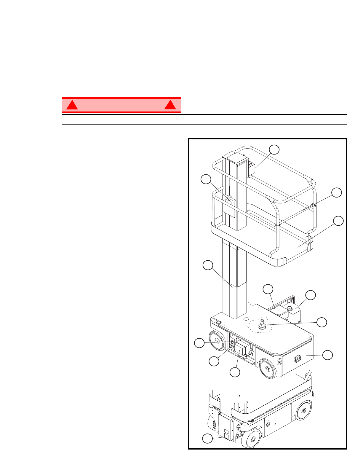
DO NOT use the maintenance platform without guardrails properly assembled and in place
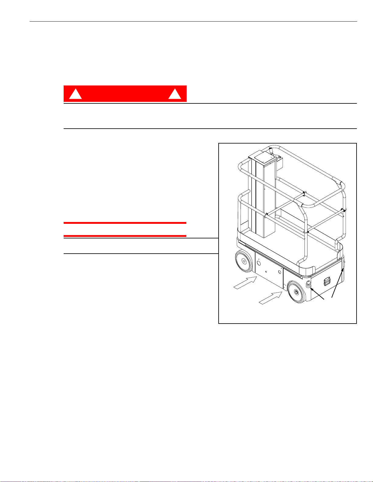
1. Platform
2. Entry Bar
3. Elevating Mast
4. Platform Controls
5. Manual Case
6. Electrical Box
7. Hydraulic Reservoir
8. Level Sensor
9. Battery Tray
10. Emergency Lowering Valve
11. Battery Charger
12. Drive Relief Valve
13. Charger Outlet Plug
!
4
5
3
Figure 1: TM12 Series
2
1
6
7
8
13
9
12
11
10
Page 3 Operation Manual
Page 7
S
PECIAL
Special Limitations
L
IMITATIONS
Trave l with the platform raised is limited to creep speed range.
Elevating the platform is limited to firm, level surfaces only.
DANGER
! !
The elev ating function shall ONLY be used when the work platform is level and on a firm surface.
The work platform is NOT intended to be driven over uneven, rough, or soft terrain.
P
LATFORM
The maximum platform capacity for the TM12 is 227 kg (500 lbs). Two people may occupy the platform
indoors, while only one may occupy the platform outdoors.
DANGER
! !
DO NOT exceed the maximum platform capacity or the platform occupancy limits for this machine.
M
ANUAL
Manual force is the force applied by the occupants to objects such as walls or other structures outside the
work platfor m .
F
C
APACITY
ORCE
The maximum allowable manual force is limited to 200 N (45 lbs.) of force per occupant, with a maximum
of 400 N (90 lbs.) for two occupants.
DANGER
! !
DO NOT exceed the maximum amount of manual force for this machine.
B
EAUFORT
Never operate the machine when wind speeds exceed 12.5m/s (28mph) [Beaufort scale 6].
BEAUFORT
RATING
3 3,4~5,4 12,25~19,4 11.5~17.75 7.5~12.0 Papers and thin branches move, flags wave.
4 5,4~8,0 19,4~28,8 17.75~26.25 12.0~18 Dust is raised, paper whirls up, and small branches sway.
5 8,0~10,8 28,8~38,9 26.25~35.5 18~24.25 Shrubs with leaves start swaying. Wave crests are apparent in ponds or swamps.
6 10,8~13,9 38,9~50,0 35.5~45.5 24.5~31 Tree branches move. Power lines whistle. It is difficult to open an umbrella.
7 13,9~17,2 50,0~61,9 45.5~56.5 31.~38.5 Whole trees sway. It is difficult to walk against the wind.
m/s km/h ft/s mph
S
WIND SPEED
CALE
GROUND CONDITIONS
Operation Manual Page 4
Page 8
Controls and Indicators
C
ONTROLS
The operator shall know the location of each control and indicator and have a thorough knowledge of the
function and operation of each before attempting to operate the unit.
AND
I
NDICATORS
2
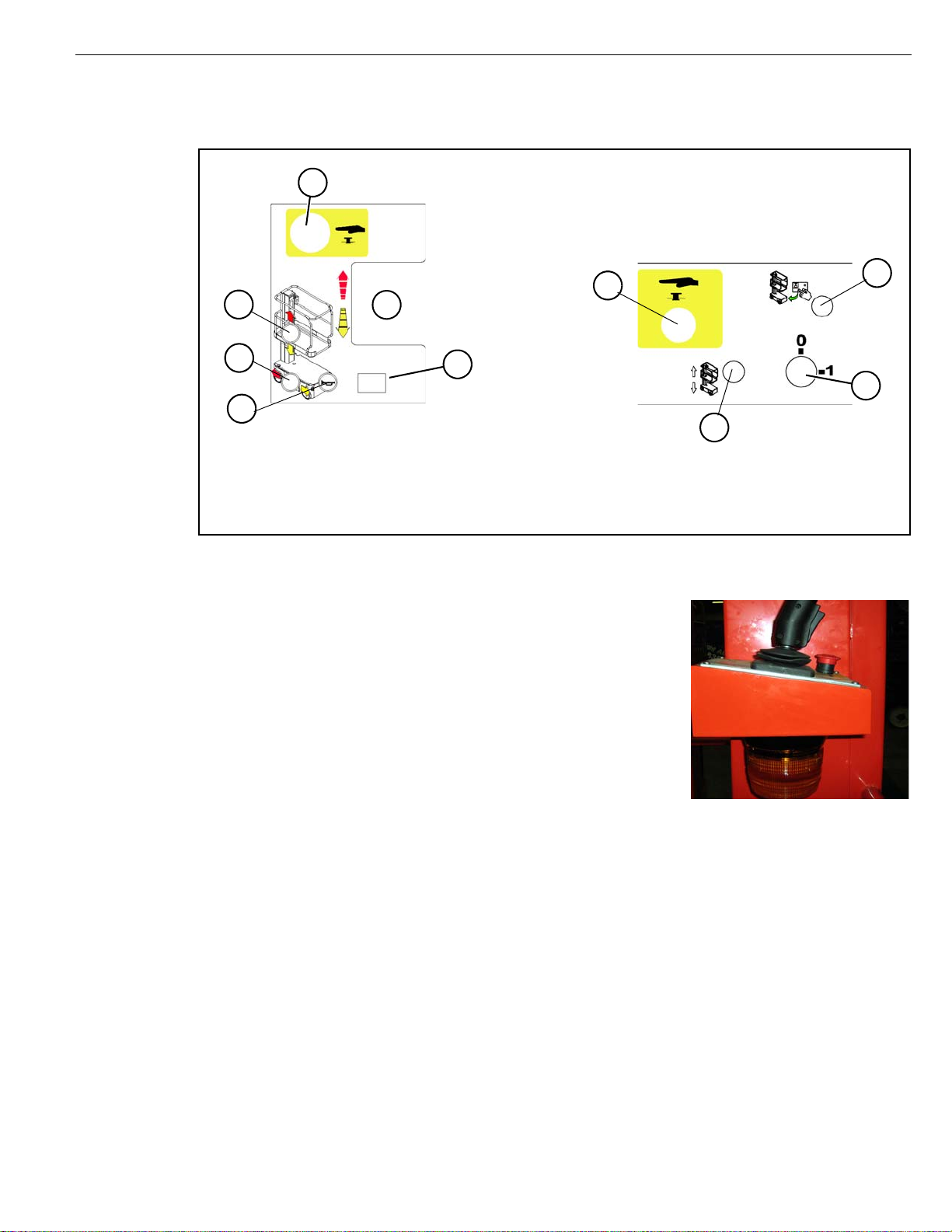
Figure 2: Controls and Indicators
Platform Controller
Chassis Controller (Right Side)
3
4
1
10
9
Side View
1. Joystick
2. Emergency Stop
3. Lift Button
4. Drive Button
5. Emergency Stop (chassis)
W
ARNING
The warning beacon is located beneath the upper control panel.
The beacon flashes when the machine is s witched on and capab le
of powered motion.
B
EACON
Top View
6. Toggle switch (chassis)
7. Enable button
8. Keyswitch
9. Horn Button
10. Display
5
7
8
6
Figure 2A: Flashing Warning Beacon
P
RE
-O
PERATION
NOTE: Carefully read, understand and follow all safety rules, operating instructions, labels and National Safety
Instructions/Requirements. Perform the following steps each day before use.
1. Open the Chassis Door and inspect for damage, fluid leaks or missing parts.
2. Check the lev el of the h ydraulic fluid with the platform fully lowered. Open the Chassis Door and remove
the reservoir cap, flui d should be visible on the dipstick. Add recommended hydraulic fluid if necessary.
See “Specifications” on page 14.
3. Check that the fluid level in the batteries is correct. See “Battery Maintenance” on page 11.
4. Verify that the batteries are charged.
5. Check that the A.C. extension cord has been disconnected from the chassis outlet.
6. Check that all guardrails are in place and all fasteners are properly tightened.
7. Inspect the machine thoroughly for cracked welds and structural damage, loose or missing hardware,
hydraulic leaks, damaged control cable and loose wire connections.
Page 5 Operation Manual
S
AFETY
I
NSPECTION
Page 9
S
YSTEM
F
UNCTION
Refer to Figure 1 and Figure 2 for the locations of various controls and indicators.
I
NSPECTION
System Function Inspection
!
WARNING
STAND CLEAR of the work platform while performing the following checks.
Before operat ing the machine, survey the work area for surface hazards such as holes, drop-offs, bumps
and debris.
Check in ALL directions, including above the work platform, for obstructions and electrical cond u cto rs.
Protect the control console cable from possible damage while performing checks.
1. Move the machine, if necessary, to an unobstructed area to allow for full elevation.
2. Turn the Chassis and Platform Emergency Stop Switches ON by pulling the buttons out.
3. Turn the Chassis Key Switch to ON.
4. Push the Chassis Lift Switch to the UP position and fully elevate the platform.
5. Visually inspect the mast assembly for damage or erratic operation. Check for missing or loose parts.
6. Verify that the depression mechanism supports have rotated into position under the machine.
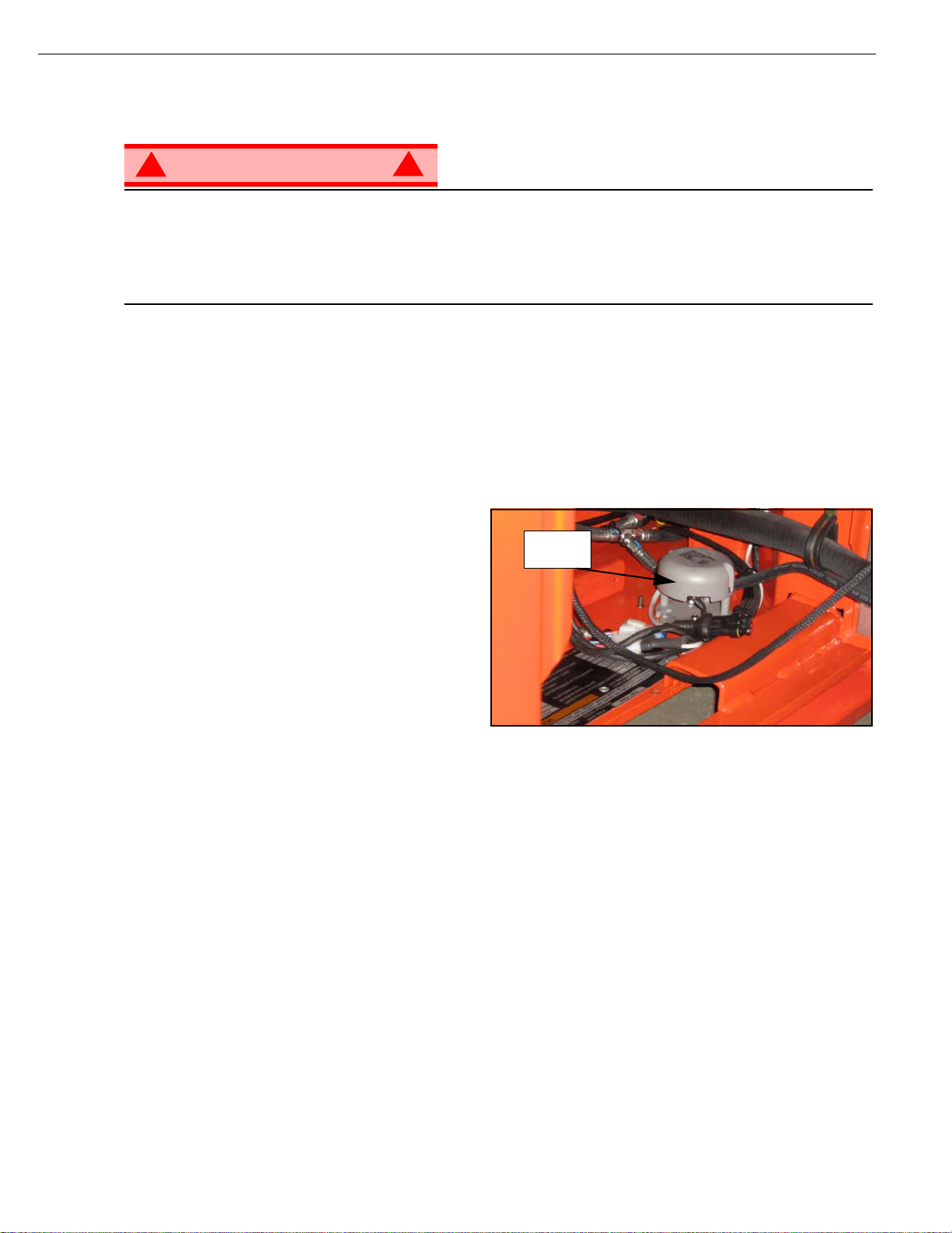
7. The Level Sensor operation:
The Lev el Sensor is located on the chassis of the
machine.
These units are factory sealed, pre-set and
require no recalibration or adjustment.
!
Figure 3: Level Sensor Location
Level
Sensor
8. Raise the platform, then partially lower the
platform by pushing the Chassis Lift Switch to
DOWN, and check the operation of the audib le
lowering alarm.
9. Check the Chassis Emergency Lowering
Valve for proper operation (see Figure 4):
a. Open the valve by pulling the knob out.
b. Once the platform is fully lowered, close the valve by releasing the knob.
10. Push the Chassis Emergency Stop Switch down to the OFF position. All machine functions should be
disabled. Pull out the Chassis Emergency Stop Switch to resume.
11. Mount the platform.
12. Chec k t hat the route is clear of persons, obstructions, holes and drop-offs, is level and capable of supporting the wheel loads.
13. After mounting platform, lower the bar across the entrance.
14. Select DRIVe mode.
15. While depressing the Interlock Switch, slowly position the Control Lever to FORWARD then REVERSE
to check for spe ed and directio nal contro l. The farther you push or pull the Control Leve r from center t he
faster the machine will travel.
16. Push the Steering Switch RIGHT then LEFT to check for steering control.
17. Push the Platform Emergency Stop Switch down to the OFF position. All machine functions should be
disabled. Pull out the Platform Emergency Stop Switch to resume.
Operation Manual Page 6
Page 10

Operation
O
PERATION
Before operating the machine, ensure that the Pre-Operation Safety Inspection has been completed and
that any deficiencies have been corrected. Never operate a damaged or malfunctioning machine. The
operator must be thoroughly trained on this machine.
T
RAVEL
1. Check that the route is clear of people, obstructions, holes and drop-offs, is level and is capable of supporting wheel loads.
2. Verify that the Chassis Key Switch is turned to ON and the Chassis Emergency Stop Switch is ON, (pull
button out).
3. After mounting the platform, lower the bar across entrance.
4. Check clearances above, below and to the sides of the machine.
5. Pull the Controller Emergency Stop switch up to the ON position.
6. Select DRIVE mode.
7. While depressing the Interlock Switch, slo wly push or pull the Control Le v er to FOR WARD or REVERSE
position to travel in the desired direction. The farther you push or pull the Control Lever from center the
faster the machine will travel.
S
TEERING
W
ITH
P
LATFORM
L
OWERED
NOTE: Steering is not self-centering. Wheels must be returned to straight ahead position by operating the Steering
Switch.
1. Select DRIVE mode.
2. While depressing the Interloc k Switch, push the Steering Switch to RIGHT or LEFT to turn the wheels in
the desired direction. Observe the tires while maneuvering the machine to ensure proper direction.
E
LEVATING
1. Select LIFT mode.
2. While depressing the Interlock Switch, push Control Lever forward to UP, the farther you push the Control Lever the faster the Platform will elevate.
3. If the machine is not level the Tilt Alarm will sound and the machine will not lift or drive. If the Tilt alarm
sounds the platform must be low e re d an d th e mach ine moved to a level loca tio n be fore attempting to reelevate the Platform.
T
RAVEL
NOTE: The machine will travel at reduced speed when the platform is elevated.
1. Check that the route is clear of persons, obstructions, holes and drop-offs, is level and capable of supporting the wheel loads.
2. Check clearances above, below and to the sides of the platform.
3. Select DRIVE mode.
4. While depressing the Interlock Switch, push Control Le v er to FOR WARD or REVERSE for desired direction of travel.
5. If the machine is not level the Tilt Alarm will sound and the machine will not lift or drive. If the Tilt alarm
sounds the platform must be low e re d an d th e mach ine moved to a level loca tio n be fore attempting to reelevate the Platform.
W
P
ITH
LATFORM
P
LATFORM
E
LEVATED
L
OWERING
1. Select LIFT mode.
2. While depressing the Interlock Switch, pull back on the Control Lever.
Page 7 Operation Manual
P
LATFORM
Page 11
E
MERGENCY
L
OWERING
Operation
!
WARNING
If the platform should fail to lower, NEVER climb down the elevating assembly.
Stand clear of the elevating assembly while operating the Emergency Lowering Valve Knob.
Ask a person on the ground to open the Emergency
Lowering Valve to lower the platform. The Emergency
Lowering Valve is located at the front of the chassis.
1. Open the Emergency Lowering Valve by pulling the
knob out.
2. To close, release the knob.
NOTE: The platform will not elevate if the Emergency Lowering
Valve is open.
P
ARKING
Perform the following procedure only when the machine will not operate under its own power and it is necessary to move the machine, or when winching onto a trailer to transport.
1. Remove the spring compression nut so the
spring is loose and the brake bars are away
from the tires.
2. The machine will now roll when pushed or
pulled.
B
RAKE
R
!
ELEASE
Figure 4: Emergency Lowering Valve
Emergency Lowering Valve
Figure 5: Parking Brake Release
Spring
Compression
Nut
After moving the machine and before normal operation:
1. Replace the spring compression nu t and
tighten until the spring measures 22,2-22,9
cm (8¾”-9”) in length, verify that the brake
bars have fully engaged the tires before the
machine is operated.
!
WARNING
Never tow faster than 0,3 m/sec. (1 ft./sec.).
Never operate the machine with the parking brakes released. Serious injury or damage could result.
A
FTER
1. Ensure that the platform is fully lowered.
2. Park the machine on a firm level surface, preferably under cover, secure against vandals, children and
3. Turn the Chassis Key Switch to OFF and remove the key to prevent unauthorized operation.
U
SE
E
ACH
unauthorized operation.
D
!
AY
22,2 cm to
22,9 cm
”
Operation Manual Page 8
Page 12
Transporting the Machine
T
RANSPORTING
THE
M
ACHINE
BY C
BY F
Forklifting is for transport only.
See specifications for weight of machine and be certain that forklift is of adequate capacity to lift the
machine.
BY T
1. Maneuver the machine into transport position and
2. Secure the machine to the transpor t vehicle with
RANE
Secure the straps to chassis lifting/tie down points only.
ORKLIFT
DANGER
! !
Forklift from the side by lifting under the Chassis.
RUCK
chock wheels.
chains or straps of adequate load capacity
attached to the chassis lifting/tie down points.
Figure 6: Transporting the Machine
CAUTION
Overtightening of the chains or straps attached to the
Tie Down lugs may result in damage to the machine
Forklift From
Side
Typical Tie Down/Lift Points
(D-Rings)
H
OUR
To access the hour meter function perform the following steps.
1. Climb into the basket (with the machine powered up)
2. Push the platform emergency stop button.
3. Hold down the following buttons, Horn and Lift.
4. While holding the buttons twist the emergency stop button to return power to the machine.
M
ETER
5. “hr” will now be displayed on the readout, Pressing the right turn button will scroll through the accumulated hours two digits at a time. F o r e xample , if pressing the right turn button once displa ys “20”, pressing it
a 2nd time displays “58”, and pressing it a 3rd time displays “hr”, the elapsed time of operation is 2058
hours.
Page 9 Operation Manual
Page 13
M
AINTENANCE
Maintenance
!
WARNING
Never perform service while the platform is elevated without first blocking the elevating assembly.
DO NOT stand in the elevating assembly area while deploying or storing the brace.
B
LOCKING
I
NSTALLATION
1. Park the machine on firm level ground.
2. Verify that both Emergency Stop Switches are ON.
3. Turn and hold the Chassis Key Switch to CHASSIS.
4. Position the Chassis Lift Switch to UP and elevate the platform
approximately 1,2 m (4 ft.).
5. Place a solid wood bl ock, 51mm x 100mm x 45cm (2”x 4”x18”)
between the second mast section and Chassis just behind the
mast assembly.
6. Push the Chassis Lift Switch to the DOWN position and gradually
lower the platform until the second mast section is supported by
the block.
R
EMOVAL
1. Push the Chassis Lift Switch to the UP position and g r aduall y raise platform until the wood block can be
removed.
2. Remove the block.
3. Push the Chassis Lift Switch to the DOWN position and completely lower the platform.
THE
E
LEVATING
!
Figure 7: Supporting the Elevating Assembly
A
SSEMBLY
Number 2 Mast
Wood Block
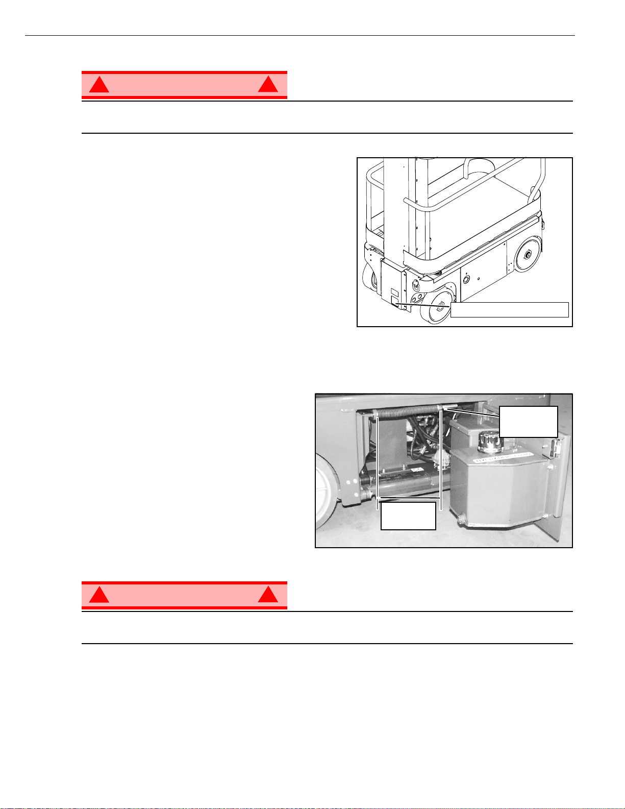
H
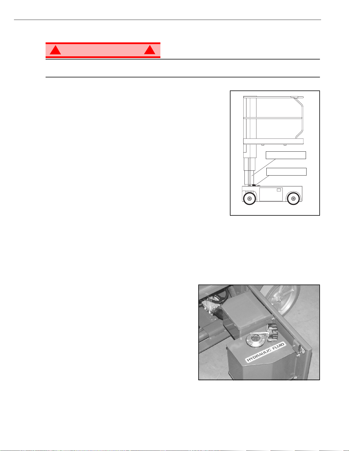
YDRAULIC
The hydraulic fluid reservoir is located in the chassis door.
NOTE: Never add fluid if the platform is elevated.
C
HECK HYDRAULIC FLUID
1. Make sure th at the platform is fully lowered.
2. Open the chassis door.
3. Remov e the filler cap from the hydraulic fluid reservoir.
4. Check the fluid level on the dipstick on the filler cap.
5. Add the appropriate fluid to b ring the lev el to the FULL
mark. See “Specifications” on page 14
F
LUID
Figure 8: Hydraulic Fluid Reservoir and Dipstick
Operation Manual Page 10
Page 14
Maintenance
B
ATTERY
M
AINTENANCE
!
WARNING
Hazard of explosive gas mixture. Keep sparks, flame, and smoking material away from batteries.
Always wear safety glasses when working near batteries.
Battery fluid is highly corrosive. Thoroughly rinse away any spilled fluid with clean water.
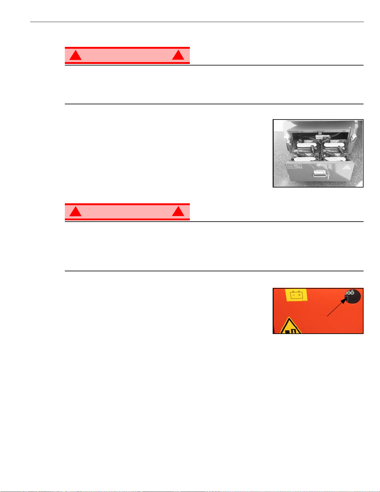
Always replace batteries with Snorkel batteries or manufacturer approved replacements weighing 26,3 kg (58 lbs.)
each.
!
Figure 9: Access to Batteries
• Check the battery fluid level daily , especially if the machine is being
used in a warm, dry climate.
• Keep the terminals and tops of the batteries clean.
• Refer to the Service Manual to extend battery life and for complete
service instructions.
B
ATTERY CHARGING
!
WARNING
Charge the batteries in a well ventilated area.
Do not charge the batteries when the machine is near a source of sparks or flames.
Permanent damage to the batteries will result if the batteries are not immediately recharged after discharging.
Never leave the battery charger operating for more than two days.
Never disconnect the cables from the batteries when the charger is operating.
Keep the charger dry.
!
Figure 10: Battery Charge Indicator
1. Check the battery fluid level. If the battery fluid level is lower than 10 mm (3/8
in.) above the plates add distilled water only.
2. Connect an extension cord (1,5 mm² [12 gauge] minimum conductor diameter; 15 m (50 ft.) maximum length) to the charger plug located at the left side
of the chassis.
3. The charger turns on automatically after a short delay. Look through the
charge indicator cutout to check the state of charge.
• 0 - 50% charge:
• First Light -BLINKING-
• Second and Third Light -OFF-
• 50% - 75% Charge:
•First Light -ON-
• Second Light -BLINKING-
• Third Light -OFF-
• 75% - 100% Charge:
• First and Second Light -ON-
• Third Light - BLINKING-
• Charge Complete
• All Lights -ON-
• The charger automatically shuts down to low current after charging is complete and all lights turn ON.
• The charger continues at low current (equalizing charge) for 3-4 hours, then charging current shuts off completely.
4. Lights remain ON until the AC power supply is disconnected.
Battery indicator
NOTE: The battery charger circuit must be used with a GFI (Ground Fault Interrupt) outlet.
NOTE: DO NOT operate the machine while the charger is plugged in.
Page 11 Operation Manual
Page 15

I
NSPECTION
Inspection and Maintenance Schedule
AND
The Complete Inspection consists of periodic visual and operational checks, along with periodic minor
adjustments that assure proper performance. Daily inspection will prevent abnormal wear and prolong the
life of all systems. The inspection and maintenance schedule should be performed at the specified intervals. Inspection and maintenance shall be performed by personnel who are trained and familiar with
mechanical and electrical proced u re s.
M
AINTENANCE
S
CHEDULE
!
WARNING
Before performing preventative maintenance, familiarize yourself with the operation of the machine.
Always block the elevating assembly whenever it is necessary to perform maintenance while the
platform is elevated.
The daily preventative maintenance checklist has been designed for machine service and maintenance.
Please photocopy the Daily Pre v en tativ e Maintenance Chec klist and use t he chec klist when inspecting the
machine.
!
Operation Manual Page 12
Page 16

Daily Preventative Maintenance Checklist
D
AILY
M
AINTENANCE
P
REVENTATIVE
T
ABLE KEY
M
AINTENANCE
C
HECKLIST
P
REVENTATIVE MAINTENANCE
R
EPORT
Y = Yes/Ac ceptable
N = No/Not Acceptable
R = Repaired/Acceptable
COMPONENT INSPECTION OR SERVICES Y N R
Battery
Chassis
Control Cable
Controller Check switch operation.
Drive Motors Check for operation and leaks.
Elevating Assembly Inspect for structural cracks.
Emergency Hydraulic
System
Check electrolyte level.
Check battery cable condition.
Check hoses for pinch or rubbing points.
Check welds for cracks.
Check the exterior of the cable for pinching,
binding or wear.
Operate the emergency lowering valve and
check for serviceability.
Date: _______________________________________
Owner:______________________________________
Model No: ___________________________________
Serial No:____________________________________
Serviced By: _________________________________
COMPONENT INSPECTION OR SERVICES Y N R
Entire Unit Check for and repair collision damage.
Hydraulic Fluid Check fluid level.
Hydraulic Pump Check for hose fitting leaks.
Hydraulic System Check for leaks.
Labels
Platform Deck and
Rails
Platform Deck and
Rails
Tires Check for damage.
Check for peeling, missing, or unreadable
labels & replace.
Check welds for cracks.
Check condition of deck.
Page 13 Operation Manual
Page 17

S
PECIFICATIONS
ITEM TM12
Platform Size 73,7 cm x 1,04 m (29 in. x 41 in.)
Maximum Platform Capacity 227 kg (500 lbs.)
Maximum Number of Occupants 2 People indoors/1 person outdoors
Height
Working Height
Maximum Platform Height
Minimum Platform Height
Dimensions
Weight
Overall Width
Overall Height
Overall Length
Drive Speed
Platform Lowered
Platform Raised
Energy Source 24V battery pack
Four 220 ampere hour, 6 Volt batteries, min. wt. 26,3 kg (58 lbs.) each
System Voltage 24 VDC
Battery Charger 20 AMP, 220 V AC 50Hz
Battery Duty Cycle 25% for 8 Hours
Hydraulic Reservoir Capacity 7,2 L (1.9 gal)
Maximum Hydraulic System Pressure 165 bar (2400 psi)
Hydraulic Fluid
Normal above 32° F [0° C]
Low Temp. below 32° F [0° C]
below 0° F [-17° C]
Lift System One Single Stage Lift Cylinder
Drive Control Proportional
Control System
Horizontal Drive Dual Front Wheel
Tires 30,5 cm (12 in.) diameter solid rubber, Non-marking
Parking Brakes Dual, Spring Applied, Hydraulic Release
Turning Radius 37 cm (14.5 in.) Inside
Maximum Gradeability 14º (25%)
Wheel Base 97,8 cm (38.5 in.)
Guardrails 1,10 m (43 in.)
Toeboard 152 mm (6 in.)
Noise Level
Proportional Control Handle with Interlock, Selector Switch,
Red Mushroom Emergency Stop Switches
5,83 m (19 ft.)
3,83 m (12.5 ft.)
48,3 cm (19 in.)
776 kg (1710 lbs.)
76 cm (30 in.)
165 cm (65 in.)
1,36 m (53.5 in.)
3,65 km/h (2.27 mph)
0,87 km/h (0.54 mph)
4 HP DC electric motor
ISO #46
ISO #32
ISO #15
Specifications
*Specifications are subject to change without notice. Hot weather or heavy use may affect performance.
Refer to the Service Manual for complete parts and service information.
This machine meets or exceeds all applicable CE and GS machinery directive requirements.
Operation Manual Page 14
Page 18

Specifications
Page 15 Operation Manual
Page 19

TM 12
Serial Numbers 50211 – Current
FRANÇAIS
Lors des communications avec Snorkel pour des informations au sujet de l’entretien ou des pièces, ne pas oublier d’inclure
les NUMÉROS DE MODÈLE et DE SÉRIE inscrits sur la plaque signalétique. Si la plaque signalétique manque, le
NUMÉRO DE SÉRIE est également estampé sur le dessus du châssis, au-dessus de l’axe pivot avant.
www.snorkelusa.com
Page 20

Page 21

GUIDE DE L'OPÉRATEUR
AVERTISSEMENT
Tout le personnel devra lire soigneusement, comprendre et re spe cter tou tes le s r ègles de s écurit é
et instructions d'utilisation avant d'utiliser ou d'effectuer des travaux de maintenance sur une
Règles de sécurité
Risque d'électrocution Risque de basculement Risque de collision Risque de chute
plate-forme de travail aérien Snorkel.
CETTE MACHINE N'EST PAS
UTILISATION DE LA PLATE-FORME DE TRAVAIL AÉRIEN : Cette plate-forme est destinée à lever le personnel et ses outi ls ainsi que les
matériaux utilisés pour effectuer le travail. Elle est conçue pour les travaux de réparation et de montage situés en hauteur (plafonds, g rues,
toitures, bâtiments, etc.). Toute autre utilisation de cette plate-forme de travail aérien est interdite !
CETTE PLA TE-FORME DE TRAV AIL AÉRIEN N'EST PAS ISOLÉE ! Pour cette raison, il est impérat if de maintenir une distance de sécurité
entre la plate-forme et les parties sous tension de l'équipement électrique !
Tout dépassement de la charge maximum admissible spécifiée est interdit ! Voir “Capacité de la plate-forme” page 4 pour plus de détails.
L'utilisation de la plate-forme de travail aérien comme outil de levage ou comme grue est in terdit !
NE JAMAIS dépasser la force manuelle autorisée pour cette machine . Voir “Force manuelle” page 4 pour plus de détails.
RÉPARTIR de façon égale toutes les charges sur la plate-forme.
NE JAMAIS utiliser la machine sans av oir aupar a v ant vérifié sur la surface de travail l'absence de trou s, déniv ellat ions , bosses , trotto irs ou débris
afin de les éviter.
UTILISER la machine uniquement sur des surfaces capables de supporter les charges par roue.
NE JAMAIS utiliser la machine quand la vitesse du vent dépasse la résistan ce nominale au v ent de la mach ine. Voir “Échelle de Beaufort” page 4
pour plus de détails.
EN CAS D'URGENCE, appuyer sur le bouton d'ARRÊT D'URGENCE pour désactiver toutes les fonctions en action.
SI L'ALARME RETENTIT pendant que la plate-forme est en position haute, ARRÊTER la p late-forme et la descendre avec précaution. Déplacer
la machine sur une surface ferme et de niveau.
Escalader le garde-corps de la plate-fo rme, pa sser de la plate-forme sur des constructions ou des structures en acier ou béton préfabriqué, etc.,
est interdit !
Le démontage de la porte d'entrée ou d'autres composants du garde-corps est interdit ! Toujours s'assurer que la porte d'entrée est fermée et
correctement verrouillée!
Il est interdit de maintenir la porte d'entrée en position ouverte quand la plate-forme est levée !
L'extension de la hauteur ou de la portée de la plate-f orme en y plaçant des échelles, échafaudages ou dispositifs similaires est interdite !
NE JAMAIS effectuer de réparations sur la machine pendant que la plate-forme est levée sans bloquer l'ensemble de levage.
INSPECTER soigneusement la machine pour vérifier l'absence de soudures fissurées, pièces de fixation desserrées ou manquantes, fuites
hydrauliques, connexions de câblage desserrées et câbles ou tuyaux endommagés avant toute utilisation.
VÉRIFIER que toutes les étiquettes sont en place et lisibles avant toute utilisation.
NE JAMAIS utiliser une machine endommagée, qui ne fonctionne pas correctement ou dont les étiquettes sont endommagées ou manquantes.
La neutralisation de tout équ ipe ment d e sécurité est interdite et présente un danger pour les personnes se tenant sur la plate-forme de travail et
sa zone d'activité.
NE JAMAIS charger les batteries près d'étincelles ou d'une flamme nue. La charge des batteries cause l'émission d'hydrogène explosif.
Les modifications de la plate-forme de travail aérien sont interdites ou autorisées seulement après approbation de
APRÈS UTILISATION, empêcher tout e utilisation non autorisée de la plate-forme de travail en coupant le contact et en retirant la clé.
ISOLÉE !
NE JAMAIS élever la plate-forme
ou conduire la machine avec la
plate-forme élevée sauf sur une
surface ferme et de niveau.
NE JAMAIS positionner la plate-
forme sans vérifier au préalable qu'il
n'existe pas d'obstructions ou
autres risques au-dessus.
NE JAMAIS grimper, se tenir
debout ou assis sur les
garde-corps ou la rampe
intermédiaire de la plate-forme.
Snorkel.
Guide de l'opérateur Page 1
Page 22

T
ABLE
DES MATIÈRES
Introduction . . . . . . . . . . . . . . . . . . . . . . . . . . . . . . . . . . . . . . . . . . . . . . . . . . . . . . . . . . . . . . . . . . . . . . . . . 3
Description générale. . . . . . . . . . . . . . . . . . . . . . . . . . . . . . . . . . . . . . . . . . . . . . . . . . . . . . . . . . . . . . . . . . 3
Restrictions spéciales . . . . . . . . . . . . . . . . . . . . . . . . . . . . . . . . . . . . . . . . . . . . . . . . . . . . . . . . . . . . . . . . 4
Capacité de la plate-forme. . . . . . . . . . . . . . . . . . . . . . . . . . . . . . . . . . . . . . . . . . . . . . . . . . . . . . . . . . . . . . . . . . . . . 4
Force manuelle. . . . . . . . . . . . . . . . . . . . . . . . . . . . . . . . . . . . . . . . . . . . . . . . . . . . . . . . . . . . . . . . . . . . . . . . . . . . . . 4
Échelle de Beaufort . . . . . . . . . . . . . . . . . . . . . . . . . . . . . . . . . . . . . . . . . . . . . . . . . . . . . . . . . . . . . . . . . . . . . . . . . . 4
Commandes et indicateurs . . . . . . . . . . . . . . . . . . . . . . . . . . . . . . . . . . . . . . . . . . . . . . . . . . . . . . . . . . . . 5
Inspection de sécurité avant utilisation . . . . . . . . . . . . . . . . . . . . . . . . . . . . . . . . . . . . . . . . . . . . . . . . . . 5
Vérification des fonctions des systèmes . . . . . . . . . . . . . . . . . . . . . . . . . . . . . . . . . . . . . . . . . . . . . . . . . 6
Utilisation. . . . . . . . . . . . . . . . . . . . . . . . . . . . . . . . . . . . . . . . . . . . . . . . . . . . . . . . . . . . . . . . . . . . . . . . . . . 7
Déplacement avec la plate-forme abaissée. . . . . . . . . . . . . . . . . . . . . . . . . . . . . . . . . . . . . . . . . . . . . . . . . . . . . . . . 7
Direction. . . . . . . . . . . . . . . . . . . . . . . . . . . . . . . . . . . . . . . . . . . . . . . . . . . . . . . . . . . . . . . . . . . . . . . . . . . . . . . . . . . 7
Élévation de la plate-forme. . . . . . . . . . . . . . . . . . . . . . . . . . . . . . . . . . . . . . . . . . . . . . . . . . . . . . . . . . . . . . . . . . . . . 7
Déplacement avec la plate-forme élevée. . . . . . . . . . . . . . . . . . . . . . . . . . . . . . . . . . . . . . . . . . . . . . . . . . . . . . . . . . 7
Abaissement de la plate-forme. . . . . . . . . . . . . . . . . . . . . . . . . . . . . . . . . . . . . . . . . . . . . . . . . . . . . . . . . . . . . . . . . . 7
Abaissement d'urgence . . . . . . . . . . . . . . . . . . . . . . . . . . . . . . . . . . . . . . . . . . . . . . . . . . . . . . . . . . . . . . . . . . . . . . . 8
Desserrage du frein de stationnement. . . . . . . . . . . . . . . . . . . . . . . . . . . . . . . . . . . . . . . . . . . . . . . . . . . . . . . . . . . . 8
Après utilisation chaque jour . . . . . . . . . . . . . . . . . . . . . . . . . . . . . . . . . . . . . . . . . . . . . . . . . . . . . . . . . . . . . . . . . . . 8
Transport de la machine. . . . . . . . . . . . . . . . . . . . . . . . . . . . . . . . . . . . . . . . . . . . . . . . . . . . . . . . . . . . . . . 9
Par grue . . . . . . . . . . . . . . . . . . . . . . . . . . . . . . . . . . . . . . . . . . . . . . . . . . . . . . . . . . . . . . . . . . . . . . . . . . . . . . . . . . . 9
Par chariot élévateur à fourche . . . . . . . . . . . . . . . . . . . . . . . . . . . . . . . . . . . . . . . . . . . . . . . . . . . . . . . . . . . . . . . . . 9
Par camion. . . . . . . . . . . . . . . . . . . . . . . . . . . . . . . . . . . . . . . . . . . . . . . . . . . . . . . . . . . . . . . . . . . . . . . . . . . . . . . . . 9
Maintenance. . . . . . . . . . . . . . . . . . . . . . . . . . . . . . . . . . . . . . . . . . . . . . . . . . . . . . . . . . . . . . . . . . . . . . . . 10
Blocage de l'ensemble de levage. . . . . . . . . . . . . . . . . . . . . . . . . . . . . . . . . . . . . . . . . . . . . . . . . . . . . . . . . . . . . . . 10
Installation. . . . . . . . . . . . . . . . . . . . . . . . . . . . . . . . . . . . . . . . . . . . . . . . . . . . . . . . . . . . . . . . . . . . . . . . . . . . . 10
Démontage . . . . . . . . . . . . . . . . . . . . . . . . . . . . . . . . . . . . . . . . . . . . . . . . . . . . . . . . . . . . . . . . . . . . . . . . . . . . 10
Liquide hydraulique . . . . . . . . . . . . . . . . . . . . . . . . . . . . . . . . . . . . . . . . . . . . . . . . . . . . . . . . . . . . . . . . . . . . . . . . . 10
Vérification du liquide hydraulique . . . . . . . . . . . . . . . . . . . . . . . . . . . . . . . . . . . . . . . . . . . . . . . . . . . . . . . . . . 10
Maintenance des batteries. . . . . . . . . . . . . . . . . . . . . . . . . . . . . . . . . . . . . . . . . . . . . . . . . . . . . . . . . . . . . . . . . . . . 11
Charge des batteries. . . . . . . . . . . . . . . . . . . . . . . . . . . . . . . . . . . . . . . . . . . . . . . . . . . . . . . . . . . . . . . . . . . . . 11
Programme d'inspection et de maintenance . . . . . . . . . . . . . . . . . . . . . . . . . . . . . . . . . . . . . . . . . . . . . 12
Liste de vérification quotidienne de maintenance préventive . . . . . . . . . . . . . . . . . . . . . . . . . . . . . . . 13
Spécifications . . . . . . . . . . . . . . . . . . . . . . . . . . . . . . . . . . . . . . . . . . . . . . . . . . . . . . . . . . . . . . . . . . . . . . 14
Page 2 Guide de l'opérateur
Page 23

I
NTRODUCTION
D
ESCRIPTION
Introduction
Ce manuel couvre tous les modèles de la plate-forme de travail aérien TM12. Il doit être rangé sur la
machine en permanenc e.
Il est indispensable de lire, comprendre et respecter toutes les règles de sécurité et instructions
d'utilisation avant d'essayer d'utiliser la machine.
GÉNÉRALE
Figure 1 : Série TM12
1. Plate-forme
4
!
AVERTISSEMENT
NE PAS utiliser la plate-forme de
maintenance sans les garde-corps
correctement montés et en place
2. Barre d'entrée
3. Mât élévateur
4. Commandes de plate-forme
5. Boîte du manuel
6. Coffret électrique
7. Réservoir hydraulique
8. Capteur de niveau
9. Bac à batteries
10. Soupape d'abaissement d'urgence
11. Chargeur de batterie
12. Soupape de décharge de
déplacement
13. Prise de sortie du chargeur
!
5
2
1
3
6
7
8
13
9
12
11
10
Guide de l'opérateur Page 3
Page 24

Restrictions spéciales
R
ESTRICTIONS
Tout déplacement avec la plate-forme levée est limitée à la gamme de vitesses très lentes.
L'élévation de la plate-forme est limitée uniquement aux surfaces fermes et de niveau.
! !
La fonction d'élévation sera utilisée SEULEMENT quand la plate-forme de travail est de niveau et sur une
surface ferme.
La plate-forme de travail N'EST PAS CONÇUE pour être conduite sur un terrain inégal, non nivelé ou
mou.
C
APACITÉ
La capacité maximale de la plate-forme pour le modèle TM12 est de 227 kg. Deux personnes peuvent
occuper la plate-forme à l'intérieur, mais une seule à l'extérieur.
! !
NE PAS dépasser la capacité maximale de la plate-forme ni ses limites d'occupation pour cette
machine.
SPÉCIALES
DANGER
DE LA PLATE
DANGER
-
FORME
F
ORCE
La force manuelle est la force appliquée par les occupants aux objets tels que les murs ou autres
structures extérieures à la plate-forme de travail.
La force manuelle maximale admissible est limitée à 200 N de force par occupant, avec un maximum
de 400 N pour deux occupants.
! !
NE PAS dépasser la valeur maximale de force manuelle pour cette machine.
É
CHELLE
Ne jamais utiliser la machine quand la vitesse du vent dépasse 12.5m/s (28mph) [force 6 sur l'échelle de
Beaufort].
ÉCHELLE DE
BEAUFORT
3 3,4~5,4 12,25~19,4 11,5~17,75 7,5~12,0 Les papiers et branches fines bougent ; les drapeaux ondulent.
4 5,4~8,0 19,4~28,8 17,75~26,25 12,0~18 La poussière vole, les papiers tourbillonnent et les petites branches oscillent.
5 8,0~10,8 28,8~38,9 26,25~35,5 18~24,25
6 10,8~13,9 38,9~50,0 35,5~45,5 24,5~31
7 13,9~17,2 50,0~61,9 45,5~56,5 31~38,5 Les arbres oscillent au complet. Il est difficile de marcher face au vent.
m/s km/h pi/s mi/h
MANUELLE
DANGER
DE
B
VITESSE DU VENT
EAUFORT
CONDITIONS AU SOL
Les arbustes portant des feuilles commencent à osciller. On voit les crêtes des vagues dans les
mares ou les marais.
Les branches des arbres bougent. Les lignes électriques sifflent. Il est difficile d'ouvrir
un parapluie.
Page 4 Guide de l'opérateur
Page 25

C
OMMANDES
Commandes et indicateurs
ET INDICATEURS
L'opérateur doit connaître l'emplacement de chaque commande et indicateur et avoir une connaissance
approfondie de la fonction et de l'utilisation de tous avant d'essayer d'utiliser la machine.
Figure 2 : Commandes et indicateurs
Contrôleur de plate-forme
2
Contrôleur de châssis (côté droit)
B
ALISE
3
4
1
10
9
Vue de côté
1. Manche à balai
2. Arrêt d'urgence
3. Bouton de montée
4. Bouton de déplacement
5. Arrêt d'urgence (châssis)
D'
AVERTISSEMENT
La balise d'avertissement est située sous le panneau de
commande supérieur.
La balise clignote quand la machine est alimentée et capable du
mouvement actionné.
Vue de dessus
6. Commutateur à bascule (châssis)
7. Bouton d'activation
8. Interrupteur à clé
9. Bouton d'avertisseur sonore
10. Affichage
5
7
8
6
I
NSPECTION
NOTE : Lire soigneusement, comprendre et respecter toutes les règles de sécurité, instructions d'utilisation, étiquettes
et instructions/exigences nationales de sécurité. Chaque jour avant utilisation, exécuter les étapes suivantes.
1. Ouvrir la porte du châssis et vérifier l'absence de dommages, fuites de liquide ou pièces manquantes.
2. Vérifier le niveau de liquide hydraulique avec la plate-forme complètement abaissée. Ouvrir la porte du
3. Vérifier que le niv e au de liquide dans les ba tteries est correct. Voir “Maintenance des batteries” page 11.
4. Vérifier la charge des batteries.
5. Vérifier que la rallonge c.a. a été débranchée de la prise de courant du châssis.
6. Vérifier que tous les garde-corps sont en place et toutes les fixations correctement serrées.
7. Inspecter soigneusement la machine pour vérifier l'absence de soudures fissurées et dommages
Guide de l'opérateur Page 5
DE SÉCURITÉ
châssis et retirer le bouchon du réservoir ; le liquide devrait être visible sur la jauge. Si nécessaire,
ajouter du liquide hydraulique recommandé. Voir “Spécifications” page 14.
structurels, pièces de fixation desserrées ou manquantes, fuites hydrauliques, câble de commande
endommagé et connex ions de câblage desserrées.
AVANT
UTILISATION
Page 26

Vérification des fonctions des systèmes
V
ÉRIFICATION
Se référer à la Figure 1 et la Figure 2 pour les emplacements des commandes et indicateurs.
DES FONCTIONS
DES SYSTÈMES
!
AVERTISSEMENT
SE TENIR À L'ÉCART de la plate-forme de travail pour effectuer les vérifications suivantes.
Av ant d'utiliser la machine, contrôler sur la surface de trav ail l'absence de trous, dénivellations, bosses
et débris.
Vérifier dans TOUTES les directions, y compris au-dessus de la plate-forme de travail, l'absence
d'obstructions et conducteurs électriques.
Protéger le câble de la console de commande de tout dommage possible en effectuant les
vérifications.
1. Si nécessaire, déplacer la machine dans une zone dégagée po ur pouvoir élever complètement la
plate-forme.
2. Activer les interrupteurs d'arrêt d'urgence du châssis et de la pl ate-forme en tirant sur les boutons.
3. Tourner l'interrupteur à clé du châssis en position de marche.
4. Pousser le commutateur de levage du châssis en position de LEVAGE et élever complètement la
plate-forme.
5. Vérifier visuellement l'ensemble de mât pour déceler les dommages ou un fonctionnement irr égulier.
Vérifier l'absence de pièces manquantes ou desserrées.
6. Vérifier que les supports de mécanisme à dépression ont tourné en position sous la machine.
7. Vérifier le fonctionnement du capteur de niveau :
Les unités de sonde d'inclinaison sont usine
scellée, prérèglent et n'exigent aucun
recalibrage ou ajustement.
!
Figure 3 : Emplacement du capteur de niveau
Capteur de niveau
8. Soulevez le Plaform.
9. Abaisser partiellement la plate-forme en
poussant le commutateur d'abaissement du
châssis en position d'ABAISSEMENT, et
vérifier le fonctionnement de l'alarme sonore
d'abaissement.
10. Vérifier le fonctionnement de la soupape
d'abaissement d'urgence (voir Figure 4) :
a. Ouvrir la soupape en tirant sur le bouton.
b. Une fois la plate-forme complètement abaissée, fermer la soupape en relâchant le bouton.
11. Enfoncer l'interrupteur d'arrêt d'urgence du châssis en position d'arrêt. Toutes les fonctions de la
machine devraient être inopérantes. Tirer sur l'interrupteur d'arrêt d'urgence du châssis pour une
reprise des fonctions.
12. Monter la plate-forme.
13. Vérifier que le traje t ne comporte pas de personnes, obstructions , tro us et dénivellations, est de niveau
et est capable de supporter les charges par roue.
14. Après avoir monté la plate-forme, abaisser la barre en travers de l'entrée.
15. Sélectionner le mode DÉPLACEMENT.
16. Tout en appuyant sur le commutateur de verrouillage, déplacer lentement le levier de commande en
MARCHE AVANT puis en MARCHE ARRIÈRE pour vérifier la commande de vitesse et directionnelle.
Plus on pousse ou on tire le levier de commande loin de sa position centrale, plus la machine se
déplace rapidement.
17. Pousser le commutateur de direction à DROITE, puis à GAUCHE, afin de vérifier la commande de
direction.
18. Enfoncer l'interrupteur d'arrêt d'urgence de la plate-forme en position d'arrêt. Toutes les fonctions de la
machine devraient ê tre inopér ant es. Tirer su r l'inte rrupteur d'arrê t d'urgence de la p late-forme pour une
reprise des fonctions.
Page 6 Guide de l'opérateur
Page 27

U
TILISATION
Utilisation
Av ant d'utiliser la machine, s'assurer que l'inspection de sécurité avant utilisation a été eff ectuée et que les
défauts ont été corrigés. Ne jamais utiliser une machine endommagée ou qui fonctionne mal.
L'opérateur doit être parfaitement formé au fonctionnement de la machine.
D
ÉPLACEMENT
1. Vérifier que le trajet ne comporte pas de personnes, obstructions, trous et dénivellations, est de niveau
et est capable de supporter les charges par roue.
2. Vérifier que l'interrupteur à clé du châssis est tourné sur ON et que l'interrupteur d'arrêt d'urgence
du châssis est activé (bouton sorti).
3. Après avoir monté la plate-forme, abaisser la barre en travers de l'entrée.
4. Vérifier les dégagements au-dessus, en dessous et sur les côtés de la machine.
5. Tirer vers le haut l'interrupteur d'arrêt d'urgence du contrôleur en position de marche.
6. Sélectionner le mode DÉPLACEMENT.
7. Tout en appuyant sur le commutateur de verrouillage, pousser ou tirer lentement le levier de commande
en position de MARCHE AVANT ou MARCHE ARRIÈRE pour déplacer la plate-forme dans la direction
souhaitée. Plus on pousse ou on tire le le vier de commande lo in de sa position centr ale, plu s la machine
se déplace rapidement.
D
IRECTION
AVEC
LA PLATE
-
FORME ABAISSÉE
NOTE : La direction n'est pas autocentrée. Il est nécessaire de remettre les roues droites en utilisant le commutateur
de direction.
1. Sélectionner le mode DÉPLACEMENT.
2. Tout en appuyant sur le commutateur de verrouillage, pousser le commutateur de direction à DROITE
ou GAUCHE pour tourner les roues dans la direction souhaitée. Observer les roues pendant la
manoeuvre de la machine pour vérifier qu'elles se dépla cent dans la bonne direction.
É
LÉVATION
1. Sélectionner le mode LEVAGE.
2. En appuyant sur le commutateur de v errouillage , pousser le le vier de commande v ers l'a v ant en posit ion
de LEVAGE ; plus on pousse loin le levier de commande, plus la plate-forme monte vite .
3. Si la machine n'est pas de niveau, l'alarme d'inclinaison retentit et la plate-forme ne monte pas et
ne se déplace pas. Si l'alarme d'inclinaison retentit, la plate-forme doit être abaissée et la machine
déplacée sur une surface de niveau avant d'essayer de nouveau de monter la plate-forme.
D
ÉPLACEMENT
NOTE : La machine se déplace à vitesse réduite quand la plate-forme est élevée.
1. Vérifier que le trajet ne comporte pas de personnes, obstructions, trous et dénivellations, est de niveau
et est capable de supporter les charges par roue.
2. Vérifier les dégagements au-dessus, en dessous et sur les côtés de la plate-forme.
3. Sélectionner le mode DÉPLACEMENT.
4. Tout en appuyant sur le commutateur de verrouillage, pousser le levier de commande en MARCHE
AVANT ou MARCHE ARRIÈRE pour le sens de déplacement souhaité.
5. Si la machine n'est pas de niveau, l'alarme d'inclinaison retentit et la plate-forme ne monte pas
et ne se déplace pas. Si l'alarme d'inclinaison retentit, la plate-forme doit être abaissée et la machine
déplacée sur une surface de niveau avant d'essayer de nouveau de monter la plate-forme.
DE LA PLATE
AVEC
-
FORME
LA PLATE
-
FORME ÉLEVÉE
A
BAISSEMENT
1. Sélectionner le mode LEVAGE.
2. Tout en appuyant sur le commutateur de verrouillage, tirer le levier de commande vers l'arrière.
Guide de l'opérateur Page 7
DE LA PLATE
-
FORME
Page 28

Utilisation
A
BAISSEMENT
D'
URGENCE
!
AVERTISSEMENT
Si la plate-forme ne s'abaisse pas, NE JAMAIS redescendre de l'appareil de levage.
Se tenir à l'écart de l'ensemble de levage tout en actionnant le bouton de la soupape d'abaissement
d'urgence.
Demander à une personne au sol d'ouvrir la soupape
d'abaissement d'urgence afin d' abaisser la plat e-forme.
La soupape d'abaissement d'urgence est située à
l'avant du châssis.
1. Ouvrir la soupape d'abaissement d'urgence en tirant
sur le bouton.
2. Pour la fermer, relâcher le bouton.
NOTE : La plate-forme ne monte pas si la soupape
d'abaissement d'urgence est ouverte.
D
ESSERRAGE
Exécuter la procédure suivante seulement quand la machine ne fonctionne pas avec sa propre
alimentation et s'il est nécessaire de la déplacer ou de la treuiller sur une remorque pour la transporter.
1. Retirer l'écrou de compression du ressort
de façon à desserrer le r essort et d'éloigner
les barres de frein des pneus.
2. La machine peut maintenant rouler quand
elle est poussée ou tirée.
DU FREIN DE STATIONNEMENT
!
Figure 4 : Soupape d'abaissement d'urgence
Soupape d'abaissement
d'urgence
Figure 5 : Desserrage du frein de stationnement
Écrou de
compression
du ressort
Après avoir déplacé la machine et avant une
utilisation normale :
1. Remettre en place l'écrou de compression
du ressort et le serrer jusqu'à ce que le
ressort ait une longueur de 22,2-22,9 cm ;
vérifier que les barres de frein sont
enclenchées sur les roues avant d'utiliser la
machine.
!
AVERTISSEMENT
Ne jamais remorquer à une vitesse supérieur à 0,3 m/s.
Ne jamais utiliser la machine avec les freins de stationnement desserrés. Cela pourrait causer des
blessures ou des dommages graves.
A
PRÈS UTILISATION
1. S'assurer que la plate-forme est complètement abaissée.
2. Stationner la machine sur une surface ferme et de niveau, de préférence à l'abri, protégée contre les
vandales, les enfants et toute utilisation non autorisée.
3. Tourner l'interrupteur à clé du châssis en position d'arrêt et retirer la clé pour empêcher toute utilisation
non autorisée.
!
CHAQUE
JOUR
22,2 cm à
22,9 cm
”
Page 8 Guide de l'opérateur
Page 29

T
RANSPORT
Transport de la machine
DE LA MACHINE
P
AR GRUE
Fixer les sangles uniquement aux point s de levage/arrimage du châssis.
P
AR CHARIOT
DANGER
! !
Utiliser un chariot élévateur à four che pour le transport seulement.
Voir les spécifications pour le poids de la machine et vérifier que le chariot élévateur à fourche a une
capacité suffisante pour soulever la machine.
Soulever avec le ch ariot à fourche depuis le côté en
passant sous le châssis.
P
AR CAMION
1. Manoeuvrer la machine dans la position de
transport et caler les roues.
2. Attacher la machine au véhicule de transport
avec des chaînes ou des sangles de capacité
adaptée et fixées aux points de levage/arrimage
du châssis.
ÉLÉVATEUR
À
FOURCHE
Figure 6 : Transport de la machine
ATTENTION
Le fait de trop serrer les chaînes ou sangles fixées
aux tenons d'arrimage peut endommager la
machine
H
OROMÈTRE
Compteur horaire : lecture des heures.
1. Mettre la machin e sou s te nsio n .
2. Monter dans le panier.
3. Enfoncer le bouton d'arrêt d'urgence.
4. Maintenir enfoncées simultanément les touches suivantes sur le pupitre : touches montée/descente
du télescope et avertisseur sonore.
5. Tout en maintenant enfoncées ces touches, tourner le bouton d'arrêt d'urgence pour rétablir
l'alimentation de la machine.
6. La mention " hr " apparaît sur l'afficheur, vous pouvez alors arrêter de maintenir les touches
enfoncées.
7. Appuyer sur le bouton de commande de directio n à dro ite au n iveau du manipulateur pour faire défi ler
les heures accumulées. Une première pression fait apparaître une première série de deux chiffres,
une seconde pression fait apparaître une autre série de deux chiffres et une troisième pression fait
apparaître la mention " hr ". Ces d eux séries de deux chif fres combinées indiq uent le nombr e d'heures
de fonctionnement accumulées comme le montre l'exemple ci-dessous :
Élévateur à f ourche
depuis le côté
Points de levage/arrimage types
(Anneaux en D)
Première série de deux chiffres : 20
Deuxième série de deux chiffres : 58
Le nombre d'heures de f onctionnement accumulées est de 2 058 heures.
Guide de l'opérateur Page 9
Page 30

Maintenance
M
AINTENANCE
!
AVERTISSEMENT
Ne jamais effectuer de réparations pendant que la plate-forme est levée sans bloquer l'ensemble
de levage.
NE PAS rester à proximité de l'ensemble de levage pendant le déploiement ou le rangement
du renfort.
B
LOCAGE
I
NSTALLATION
1. Stationner la machine sur un sol ferme et de niveau.
2. Vérifier que les deux interrupteurs d'arrêt d'urgence sont activés.
3. Tourner et maintenir sur CHÂSSIS l'interrupteur à clé du châssis.
4. Placer le commutateur de levage du châssis en position de
LEVAGE et lever la plate-forme d'environ 1,2 m.
5. Placer un bloc de bois plein de 51 mm x 100 mm x 45 cm entre
la section du second mât et le châssis, juste derrière l'ensemble
de mât.
6. Pousser le commutateur de levage du châssis en position
d'ABAISSEMENT et abaisser progressivement la plate-forme
jusqu'à ce que la section du second mât soit supportée par
le bloc.
DE L'ENSEMBLE
!
Figure 7 : Support de l'ensemble de levage
DE LEVAGE
Mât numéro 2
Bloc de bois
D
ÉMONTAGE
1. Pousser le commutateur de levage du châssis en position de LEVAGE et soulever lentement
la plate-forme jusqu'à ce qu'il soit possible de retirer le bloc de bois.
2. Retirer le bloc.
3. Pousser le commutateur de lev age du châssis en position d'ABAISSEMENT et abaisser complètement
la plate-forme.
L
IQUIDE
Le réservoir de liquide hydr aulique est situé dans la porte du châssis.
NOTE : Ne jamais ajouter de liquide si la plate-forme est
montée.
V
ÉRIFICATION DU LIQUIDE HYDRAULIQUE
1. S'assurer que la plate-forme est complètement
abaissée.
2. Ouvrir la porte du châssis.
3. Retirer le bouchon de remplissage du réservoir
de liquide hydraulique.
4. Vérifier le niveau de liquide sur la jauge du bouchon
de remplissage.
5. Ajouter du liquide approprié pour que le niveau
atteigne la marque FULL. Voir “Spécifications” page 14
HYDRAULIQUE
Figure 8 : Réservoir de liquide hydraulique et jauge
Page 10 Guide de l'opérateur
Page 31

M
AINTENANCE
DES BATTERIES
Maintenance
Figure 9 : Accès aux batteries
!
AVERTISSEMENT
Risque de mélange de gaz explosif. Maintenir les
étincelles, flammes et cigarettes à l'écart des batteries.
Toujours porter des lunettes de sécurité pour travailler
près des batteries.
Le liquide des batteries est hautement corrosif. Rincer
soigneusement tout dév ersement de liquide av ec de l'eau
propre.
Toujours remplacer les batteries par des batteries
Snorkel ou des batteries de rechange approuv ées par le
fabricant et pesant 26,3 kg chacune.
• Vérifie r chaq u e jou r le niveau de liquide de la
batterie, en particulier si la machine est utilisée dans un climat chaud et sec.
• Si le niveau de l'électrolyte au-dessus des plaques est inférieur à 10 mm, ajouter de l'eau distillée
uniquement. NE PAS ajouter d'eau du robinet ayant une teneur élev ée en sels minéraux car cela
raccourcira la durée de vie de la batterie.
• Maintenir propres les bornes et les dessus des batteries.
• Se référer au manuel de réparation pour prolonger la durée de vie des batteries et pour des
instructions d'entretien complètes.
C
HARGE DES BATTERIES
Charger les batteries à la fin de chaque poste de travail
ou plus souvent si les batteries sont déchargées.
!
Figure 10 : Indicateur de charge des batteries
!
AVERTISSEMENT
Charger les batteries dans un endroit bien ventilé.
Ne pas charger les batteries quand la machine se trouve
près d'une source d'étincelles ou de flammes.
Les batteries subiront des dommages permanents si
elles ne sont pas rechargées immédiatement après avoir
été déchargées.
Ne jamais laisser le chargeur de batteries fonctionner pendant plus de deux jours.
Ne jamais débrancher les câbles des batteries pendant que le chargeur fonctionne.
Conserver le chargeur au sec.
1. Vérifier le niveau de liquide des batteries. Si le niveau de l'électrolyte au-dessus des plaques est
inférieur à 10 mm, ajouter de l'eau distillée uniquement.
2. Brancher une rallonge appropriée à la prise de sortie du chargeur dans la porte du module de gauche.
Brancher la rallonge dans une prise de courant reliée à la terre de tension et de fréquence correctes.
3. Le chargeur se met en marche automatiquement après un court délai. L'indicateur de charge à LED
s'allume. À la fin du cycle de charge, la LED clignote, indiquant que le chargeur est en mode de
maintenance continue. NE PAS laisser le chargeur branché pendant plus de 48 heures, car cela risque
de causer des dommages permanents aux batteries.
NOTE : Le circuit du chargeur de batteries doit être utilisé sur une prise avec interrupteur de défaut à la terre.
!
Indicateur de
charge des
batteries
NOTE : NE PAS utiliser la machine lorsque le chargeur de batteries est branché.
Guide de l'opérateur Page 11
Page 32

Programme d'inspection et de maintenance
P
ROGRAMME
L'inspection complète se compose de vérifications visuelles et opérationnelles périodiques, associées
à des réglages périodiques mineurs assurant un fonctionnement correct. Une inspection quotidienne
évitera toute usure anormale et prolongera la durée de vie de tous les systèmes. Le programme
d'inspection et de maintenance doit être exécuté aux intervalles indiqués. L'in spection et la maintenance
doivent être effectuées par du personnel ayant reçu une formation et connaissant bien les procédures
mécaniques et électriques.
D'
INSPECTION
ET DE MAINTENANCE
!
AVERTISSEMENT
Avant d'effectuer la maintenance préventive, il est bon de se familiariser avec le fonctionnement
de la machine.
Toujours bloquer l'ensemb le de levage lorsqu'il est nécessaire d'effectuer la maintenance avec
la plate -form e en position haute.
La liste de vérification quotidienne de maintenance préventive a été conçue pour l'entretien et la
maintenance de la machine. Photocopier la liste de vérification quotidienne de maintenance préventi ve
et utiliser cette liste pour inspecter la machine.
!
Page 12 Guide de l'opérateur
Page 33

L
ISTE DE VÉRIFICATION
QUOTIDIENNE
PRÉVENTIVE
L
ÉGENDE DU TABLEAU DE MAINTENANCE
Liste de vérification quotidienne de maintenance préventive
DE MAINTENANCE
R
APPORT DE MAINTENANCE PRÉVENTIVE
O = Oui/Acceptable
N = Non/Inacceptable
R = Réparé/Acceptable
COMPOSANT INSPECTION OU SERVICES O N R
Batterie
Châssis
Câble de commande
Contrôleur Vérifier le fonctionnement des commutateurs.
Moteurs
d'entraînement
Ensemble de levage Vérifier l'absence de fissures structurelles.
Système hydraulique
d'urgence
Vérifier le niveau d'électrolyte.
Vérifier l'état des câbles de batterie.
Vérifier l'absence de pincements ou de points
de frottement sur les tuyaux.
Vérifier l'absence de fissures au niveau des
soudures.
Vérifier à l'extérieur du câble l'absence
de traces de pincement, torsion ou usure.
Vérifier le fonctionnement et l'absence
de fuites.
Actionner la soupape d'abaissement d'urgence
et vérifier son fonctionnement.
Date :_______________________________________
Propriétaire : _________________________________
N° de modèle :________________________________
N° de série :__________________________________
Entretenu par :________________________________
COMPOSANT INSPECTION OU SERVICES O N R
Unité totale
Liquide hydraulique Vérifier le niveau de liquide.
Pompe hydraulique
Système hydraulique Vérifier l'absence de fuites.
Étiquettes
Plancher de plate-
forme et garde-corps
Plancher de plate-
forme et garde-corps
Pneus Vérifier l'absence de dommages.
Vérifier l'absence de dommages causés par
des collisions et les réparer.
Vérifier l'absence de fuites aux raccords
de tuyaux.
Vérifier que les étiquettes ne soient pas
décollées, manquantes ou illisibles ; les
remplacer le cas échéant.
Vérifier l'absence de fissures au niveau des
soudures.
Vérifier l'état du plancher.
Guide de l'opérateur Page 13
Page 34

Spécifications
S
PÉCIFICATIONS
ÉLÉMENT TM12
Dimensions de la plate-forme 73,7 cm x 1,04 m
Capacité maximale de la plate-forme 227 kg
Nombre maximal d'occupants 2 personnes à l'intérieur/1 personne à l'extérieur
Hauteur
Hauteur de travail
Hauteur maximale de la plate-forme
Hauteur minimale de la plate-forme
Dimensions
Poids
Largeur totale
Hauteur totale
Longueur totale
Vitesse de déplacement
Plate-forme abaissée
Plate-forme levée
Source d'énergie Bloc de batteries 24 V
Quatre batteries de 6 volts et 220 A/h, d'un poids min.de 26,3 kg chacune
Moteur électrique c.c. de 4 HP
Tension du système 24 V c.c.
Chargeur de batterie 20 A, 220 V c.a., 50 Hz
Cycles de service des batteries 25 % pour 8 heures
Capacité du réservoir hydraulique 7,2 L
Pression maximale du système hydraulique 165 bars
Liquide hydraulique
Température normale sup. à 0 °C
Basse temp. inf. à 0 °C
Inférieure à -17 °C
Système de levage Vérin de levage à un seul étage
Commande de déplacement Proportionnelle
Système de commande
Déplacement horizontal Deux roues avant
Pneus Caoutchouc plein, diamètre 30,5 cm, non marquants
Freins de stationnement Deux, serrés par ressort et à desserrage hydraulique
Rayon de braquage 37 cm Intérieur
Pente maximale 14º (25 %)
Empattement 97,8 cm
Garde-corps 1,10 m
Garde-pieds 152 mm
Niveau de bruit
Poignée de commande proportionnelle avec commutateurs de verrouillage,
de sélection et d'arrêt d'urgence à gros bouton rouge
5,83 m
3,83 m
48,3 cm
776 kg
76 cm
165 cm
1,63 cm
3,65 km/h
0,87 km/h
ISO n°46
ISO n°32
ISO n°15
*Spécification pouvant être modifiées sans préavis. Un temps chaud ou une utilisation intensive peuvent
affecter les performances.
Se reporter au manuel de réparation pour obtenir des renseignements comp lets sur les pièces et
l'entretien.
Cette machine respecte ou dépasse les exigences des directives CE et GS applicables en matière
d'équipement.
Page 14 Guide de l'opérateur
Page 35

Spécifications
Guide de l'opérateur Page 15
Page 36

TM 12
Números de serie 50211 – Actual
ESPAÑOL
Cuando se ponga en contacto con Snorkel pasa solicitar asistencia o información sobre repuestos, incluya siempre los
NÚMERO DE SERIE y MODELO que figuran en la placa de identificación. Si esta placa se perdiera, el NÚMERO
DE SERIE se encuentra también impreso en la parte superior del chasis, por encima del pivote del eje delantero.
www.snorkelusa.com
Page 37

MANUAL DE FUNCIONAMIENTO
ADVERTENCIA
El personal debe leer atentamente, comprender y respetar todas las reglas de seguridad
e instrucciones de funcionamiento antes de utilizar o realizar operaciones de mantenimiento
Riesgo de electrocución Riesgo de volcado Riesgo de colisión Riesgo de caída
en cualquier plataforma aérea de trabajo de Snorkel.
Reglas de seguridad
ESTA MÁQUINA NO ESTÁ
PROTEGIDA. PELIGRO
DE ELECTROCUCIÓN.
USO DE LA PLATAFORMA AÉREA DE TRABAJO: El propósito de esta plataforma aérea de trabajo es el de elevar tanto a personas yherramientas,
como el material utilizado en el trabajo. Se ha diseñado para acometer las reparaciones y el montaje de trabajos y tareas en lugares de trabajo aéreos
(techos, grúas, estructuras de tejados, edificios, etc.). Su uso para otros propósitos está prohibido.
ESTA PLATAFORMA AÉREA DE TRABAJO NO ESTÁ PROTEGIDA. PELIGRO DE ELECTROCUCIÓN. Por esta razón, es muy importante guardar
una distancia de seguridad entre las partes con corriente del equipamiento eléctrico.
Está prohibido superar la carga máxima especificada permitida. Consulte “Capacidad de la plataforma” en la página 4 para obtener información
adicional.
Está prohibido el uso y funcionamiento de la plataforma aérea de trabajo como herramienta de elevación o grúa.
NUNCA supere la fuerza manual permitida para esta máquina. Consulte “Fuerza manual” en la página 4 para obtener información adicional.
DISTRIBUYA todas las cargas de la plataforma de manera uniforme sobre la misma.
NUNCA ponga en funcionamiento la máquina sin antes examinar la superficie de trabajo en busca de riesgos en la superficie, como por ejemplo hoyos,
desniveles, baches, bordillos o escombros, y evitarlos.
UTILICE la máquina sólo en aquellas superficies que puedan soportar el peso de las ruedas.
NUNCA utilice la máquina cuando la velocidad del viento supere la establecida en la escala de ésta. Consulte “Escala de Beaufort” en la página 4 para
obtener información adicional.
EN CASO DE EMERGENCIA pulse el interruptor PARADA DE EMERGENCIA para desactivar todas las funciones con alimentación.
SI SUENA LA ALARMA mientras la plataforma está elevada, DETÉNGALA y baje con cuidado la plataforma. Mueva la máquina hasta situarla en una
superficie firme y nivelada.
Está prohibido subir a la barandilla de la plataforma, ponerse de pie en ella o pasar de la plataforma a edificios o estructuras de acero o de cemento
prefabricadas, etc.
Está prohibido desmontar el portón de entrada u otros componentes de la barandilla. Asegúrese siempre de que el portón de entrada está cerrado
y bloqueado correctamente.
Está prohibido dejar el portón de entrada abierto mientras la plataforma esté elevada.
Está prohibido aumentar la altura o el recorrido de la plataforma mediante la incorporación de escaleras, andamios o sistemas similares.
NUNCA realice labores de mantenimiento en la máquina mientras la plataforma esté elevada sin antes bloquear el conjunto de elevación.
EXAMINE cuidadosamente la máquina antes de utilizarla para detectar soldaduras rotas, hardware que falte o no esté fijado, fugas hidráulicas,
conexiones con cables sueltos o cables y mangueras dañados.
COMPRUEBE que todas las etiquetas están en su sitio y son legibles.
NUNCA utilice una máquina que presente algún defecto, no funcione apropiadamente, le falten etiquetas o las etiquetas estén dañadas.
Está prohibido pasar por alto cualquier componente del equipo de seguridad, puesto que representa un peligro para las personas que trabajan
en la plataforma aérea de trabajo y en su alcance.
NUNCA cargue las baterías cerca de chispas o llamas vivas. La carga de las baterías emite gas de hidrógeno que es explosivo.
Está prohibido realizar modificaciones en la plataforma aérea de trabajo sin la aprobación de
DESPUÉS DEL USO, asegure la plataforma de trabajo apagando la llave de contacto y extrayendo la llave, para evitar que la pueda utilizar personal
no autorizado.
NUNCA eleve la plataforma
o conduzca con ella elevada
en una superficie que no esté
firme y nivelada.
NUNCA sitúe la plataforma
sin antes comprobar si existen
obstrucciones aéreas u otro
tipo de riesgo.
Snorkel.
NO se suba, ni se ponga
de pie ni se siente en
la barandilla de la plataforma
o en el larguero intermedio.
Manual de funcionamiento Página 1
Page 38

Í
NDICE
Introducción. . . . . . . . . . . . . . . . . . . . . . . . . . . . . . . . . . . . . . . . . . . . . . . . . . . . . . . . . . . . . . . . . . . . . . . . . 3
Descripción general . . . . . . . . . . . . . . . . . . . . . . . . . . . . . . . . . . . . . . . . . . . . . . . . . . . . . . . . . . . . . . . . . . 3
Limitaciones especiales . . . . . . . . . . . . . . . . . . . . . . . . . . . . . . . . . . . . . . . . . . . . . . . . . . . . . . . . . . . . . . . 4
Capacidad de la plataforma . . . . . . . . . . . . . . . . . . . . . . . . . . . . . . . . . . . . . . . . . . . . . . . . . . . . . . . . . . . . . . . . . . . . 4
Fuerza manual . . . . . . . . . . . . . . . . . . . . . . . . . . . . . . . . . . . . . . . . . . . . . . . . . . . . . . . . . . . . . . . . . . . . . . . . . . . . . . 4
Escala de Beaufort. . . . . . . . . . . . . . . . . . . . . . . . . . . . . . . . . . . . . . . . . . . . . . . . . . . . . . . . . . . . . . . . . . . . . . . . . . . 4
Controles e indicadores . . . . . . . . . . . . . . . . . . . . . . . . . . . . . . . . . . . . . . . . . . . . . . . . . . . . . . . . . . . . . . . 5
Inspección de seguridad previa al funcionamiento. . . . . . . . . . . . . . . . . . . . . . . . . . . . . . . . . . . . . . . . . 5
Inspección de la función del sistema . . . . . . . . . . . . . . . . . . . . . . . . . . . . . . . . . . . . . . . . . . . . . . . . . . . . 6
Funcionamiento. . . . . . . . . . . . . . . . . . . . . . . . . . . . . . . . . . . . . . . . . . . . . . . . . . . . . . . . . . . . . . . . . . . . . . 7
Maniobra con la plataforma bajada . . . . . . . . . . . . . . . . . . . . . . . . . . . . . . . . . . . . . . . . . . . . . . . . . . . . . . . . . . . . . . 7
Dirección . . . . . . . . . . . . . . . . . . . . . . . . . . . . . . . . . . . . . . . . . . . . . . . . . . . . . . . . . . . . . . . . . . . . . . . . . . . . . . . . . . 7
Plataforma de elevación. . . . . . . . . . . . . . . . . . . . . . . . . . . . . . . . . . . . . . . . . . . . . . . . . . . . . . . . . . . . . . . . . . . . . . . 7
Maniobra con la plataforma elevada . . . . . . . . . . . . . . . . . . . . . . . . . . . . . . . . . . . . . . . . . . . . . . . . . . . . . . . . . . . . . 7
Descenso de la plataforma. . . . . . . . . . . . . . . . . . . . . . . . . . . . . . . . . . . . . . . . . . . . . . . . . . . . . . . . . . . . . . . . . . . . . 7
Descenso de emergencia. . . . . . . . . . . . . . . . . . . . . . . . . . . . . . . . . . . . . . . . . . . . . . . . . . . . . . . . . . . . . . . . . . . . . . 8
Desactivación del freno de estacionamiento . . . . . . . . . . . . . . . . . . . . . . . . . . . . . . . . . . . . . . . . . . . . . . . . . . . . . . . 8
Después del uso diario. . . . . . . . . . . . . . . . . . . . . . . . . . . . . . . . . . . . . . . . . . . . . . . . . . . . . . . . . . . . . . . . . . . . . . . . 8
Transporte de la máquina. . . . . . . . . . . . . . . . . . . . . . . . . . . . . . . . . . . . . . . . . . . . . . . . . . . . . . . . . . . . . . 9
Con grúa. . . . . . . . . . . . . . . . . . . . . . . . . . . . . . . . . . . . . . . . . . . . . . . . . . . . . . . . . . . . . . . . . . . . . . . . . . . . . . . . . . . 9
Con horquilla elevadora . . . . . . . . . . . . . . . . . . . . . . . . . . . . . . . . . . . . . . . . . . . . . . . . . . . . . . . . . . . . . . . . . . . . . . . 9
Con un camión. . . . . . . . . . . . . . . . . . . . . . . . . . . . . . . . . . . . . . . . . . . . . . . . . . . . . . . . . . . . . . . . . . . . . . . . . . . . . . 9
Mantenimiento. . . . . . . . . . . . . . . . . . . . . . . . . . . . . . . . . . . . . . . . . . . . . . . . . . . . . . . . . . . . . . . . . . . . . . 10
Bloqueo del conjunto de elevación. . . . . . . . . . . . . . . . . . . . . . . . . . . . . . . . . . . . . . . . . . . . . . . . . . . . . . . . . . . . . . 10
Instalación. . . . . . . . . . . . . . . . . . . . . . . . . . . . . . . . . . . . . . . . . . . . . . . . . . . . . . . . . . . . . . . . . . . . . . . . . . . . . 10
Extracción . . . . . . . . . . . . . . . . . . . . . . . . . . . . . . . . . . . . . . . . . . . . . . . . . . . . . . . . . . . . . . . . . . . . . . . . . . . . . 10
Líquido hidráulico. . . . . . . . . . . . . . . . . . . . . . . . . . . . . . . . . . . . . . . . . . . . . . . . . . . . . . . . . . . . . . . . . . . . . . . . . . . 10
Compruebe el líquido hidráulico . . . . . . . . . . . . . . . . . . . . . . . . . . . . . . . . . . . . . . . . . . . . . . . . . . . . . . . . . . . . 10
Mantenimiento de la batería. . . . . . . . . . . . . . . . . . . . . . . . . . . . . . . . . . . . . . . . . . . . . . . . . . . . . . . . . . . . . . . . . . . 11
Carga de la batería . . . . . . . . . . . . . . . . . . . . . . . . . . . . . . . . . . . . . . . . . . . . . . . . . . . . . . . . . . . . . . . . . . . . . . 11
Plan de inspección y mantenimiento . . . . . . . . . . . . . . . . . . . . . . . . . . . . . . . . . . . . . . . . . . . . . . . . . . . 12
Lista de control de mantenimiento preventivo diario . . . . . . . . . . . . . . . . . . . . . . . . . . . . . . . . . . . . . . 13
Especificaciones . . . . . . . . . . . . . . . . . . . . . . . . . . . . . . . . . . . . . . . . . . . . . . . . . . . . . . . . . . . . . . . . . . . . 14
Página 2 Manual de funcionamiento
Page 39

I
NTRODUCCIÓN
D
ESCRIPCIÓN
Introducción
Este es el manual de todos los modelos de la plataforma aérea de trabajo TM12. El manual se deberá
llevar siempre en la máquina.
Lea, comprenda y respete las reglas de seguridad y las instrucciones de funcionamiento antes
de comenzar a utilizar la máquina.
GENERAL
Figure 1: Serie TM12
1. Plataforma
4
ADVERTENCIA
!
NO utilice la plataforma de mantenimiento
sin que la barandilla se encuentre
correctamente fijada en su sitio
2. Barra de entrada
3. Mástil de elevación
4. Controles de la plataforma
5. Carcasa manual
6. Caja eléctrica
7. Depósito hidráulico
8. Sensor de nivel
9. Bandeja de la batería
10. Válvula de descenso de emergencia
11. Cargador de baterías
12. Válvula de descarga
de la transmisión
13. Enchufe de salida del cargador
!
5
2
1
3
6
7
8
13
9
12
11
10
Manual de funcionamiento Página 3
Page 40

Limitaciones especiales
L
IMITACIONES
El desplazamiento con la plataforma elevada está limitado al rango de velocidad de arrastre.
La elevación de la plataforma únicamente se podrá llev ar a cabo en superficies firmes y niveladas.
! !
La función de elevación ÚNICAMENTE se utilizará cuando la plataf orma de trabajo esté nivelada y situada
sobre una superficie firme.
La plataforma de trabajo NO está preparada para utilizarla sobre un terreno irregular, en mal estado
o inestable.
C
APACIDAD
La capacidad máxima de la plataforma para el modelo TM12 es de 227 kg (500 lb). El interior
de la plataforma lo pueden ocupar dos personas, mientras que el exterior sólo puede ocuparlo una.
! !
NO supere la capacidad máxima de la plataforma ni el número límite de ocupantes de la máquina .
ESPECIALES
PELIGRO
DE LA PLATAFORMA
PELIGRO
F
UERZA
La fuerza manual es la fuerza que los ocupantes aplican a objetos como por ejemplo muros u otras
estructuras fuera de la plataforma de trabajo.
La fuerza manual máxima permitida está limitada a 200 N (45 lb) de fuerza por ocupan te, con un máximo
de 400 N (90 lb) para dos ocupantes.
! !
NO supere la cantidad máxima de fuerza manual permitida para esta máquina.
E
SCALA
No utilice nunca la máquina si la velocidad del viento supera los 12.5m/s (28 mph) [6 en la escala
de Beaufort].
CLASIFICACIÓN
DE BEAUFORT
3 3,4~5,4 12,25~19,4 11,5~17,75 7,5~12,0 Los papeles y las ramas finas se mueven; las banderas ondean.
4 5,4~8,0 19,4~28,8 17,75~26,25 12,0~18 Se levanta el polvo, los papeles se arremolinan, las ramas pequeñas se balancean.
5 8,0~10,8 28,8~38,9 26,25~35,5 18~24,25
6 10,8~13,9 38,9~50,0 35,5~45,5 24,5~31
7 13,9~17,2 50,0~61,9 45,5~56,5 31.~38,5 Los árboles enteros se balancean. Resulta difícil caminar en dirección opuesta al viento.
m/s km/h m/s mph
MANUAL
PELIGRO
DE
B
EAUFORT
VELOCIDAD DEL VIENTO
CONDICIONES DEL SUELO
Los arbustos con hojas comienzan a balancearse. Se aprecian las crestas de las olas en estanques o pantanos.
Las hojas de los árboles se mueven. Las líneas de alta tensión emiten un silbido. Resulta difícil abrir un paraguas.
Página 4 Manual de funcionamiento
Page 41

C
ONTROLES
Controles e indicadores
E
INDICADORES
El operario debe conocer a fondo la ubicación de todos los controles e indicadores, así como la función
y el funcionamiento de cada uno de ellos antes de comenzar a utilizar la unidad.
Figure 2: Controles e indicadores
Controlador de la plataforma
2
Controlador del chasis (lado derecho)
F
ARO
A
MONESTADOR
El faro amonestador está situado debajo del panel de control superior.
El faro destella cuando se enciende (con.) la máquina y capaz del
movimiento accionado.
3
4
9
Vista lateral
1. Palanca de mando
2. Parada de emergencia
3. Botón de elevación
4. Botón de transmisión
5. Parada de emergencia (chasis)
5
7
1
10
8
Vista superior
6. Interruptor basculante (chasis)
7. Botón Habilitar
8. Llave de contacto
9. Botón de la bocina
10. Pantalla
6
I
NSPECCIÓN
NOTA: Lea cuidadosamente, comprenda y respete todas las reglas de seguridad, instrucciones de funcionamiento,
etiquetas e instrucciones/requisitos de seguridad nacionales. Siga a diario estos pasos antes de comenzar.
1. Abra la puerta del chasis y compruebe si existen desperfectos , fugas de lí quido o si f altan componentes .
2. Compruebe el nivel de líquido hidráulico con la plataforma completamente bajada. Abra la puerta del
3. Compruebe si el nivel de líquido de las baterías es el adecuado. Consulte “Mantenimien to de la ba tería”
4. Compruebe si las baterías están cargadas.
5. Compruebe si el alargador CA se ha desconectado de la salida del chasis.
6. Compruebe que todas las barandillas estén correctamente colocadas y los cierres ajustados.
7. Examine cuidadosamente la máquina para detectar soldaduras rot as , daño s en la estructur a, har dw ar e
Manual de funcionamiento Página 5
DE SEGURIDAD
chasis y la tapa del depósito; el líquido se deberá apreciar en la varilla de medición. Añada el líquido
hidráulico recomendado en caso de que sea necesario. Consulte “Especificaciones” en la página 14.
en la página 11.
que falte o no esté fijado, fugas hidráulicas, cables de control da ñados o conexiones con cables sueltos.
PREVIA
AL FUNCIONAMIENTO
Page 42

Inspección de la función del sistema
I
NSPECCIÓN
Consulte Figura 1 y Figura 2 par a conocer la ubicación de los distintos controles e indicadores.
DE LA FUNCIÓN
DEL SISTEMA
ADVERTENCIA
!
ALÉJESE de la plataforma de trabajo mientr as se llevan a cabo las siguientes comprobaciones.
Antes de utilizar la máquina examine la superficie de trabajo en busca de riesgos en la superficie, como
por ejemplo hoyos, desniveles, baches o escombros.
Mire en TODAS las direcciones, incluso por encima de la plataf orma de trabajo, para comprobar si existen
obstáculos y conductores eléctricos.
Proteja el cable del panel de mandos de posibles daños durante las comprobaciones.
1. Lleve la máquina si fuera necesario hasta un área libre de obstrucciones para poder llevar a cabo
una elevación completa.
2. Coloque los interruptores de parada de emergencia del chasis y de la plataforma en la posición
de ENCENDIDO tirando de los botones.
3. Gire el interruptor con llave del chasis hasta la posición de ENCENDIDO.
4. Coloque el interruptor de elevación del chasis en la posición ARRIBA y eleve por completo
la plataforma.
5. Examine visualmente el conjunto del mástil para detectar daños o funcionamientos incorrectos.
Compruebe si falta algún componente o hay alguno suelto.
6. Compruebe que los soportes del mecanismo de depresión se han colocado en posición bajo
la máquina.
7. Compruebe el funcionamiento del sensor de nivel:
Las unidades del sensor de la inclinación son
fábrica sellada, preestablecen y no requieren
ninguna recalibración o el ajuste.
!
Figure 3: Ubicación del sensor de nivel
Sensor de nivel
8. Levante el Plaform.
9. Baje la plataforma parcialmente colocando
el interruptor de elevación del chasis
en la posición ABAJO y compruebe que
la alarma de descenso se escucha.
10. Compruebe que la válvula de descenso
de emergencia del chasis funcione
correctamente (consulte la figura 4):
a. Para abrir la válvula, tire del botón hacia fuera.
b. Una vez que la plataforma está completamente bajada, suelte el botón para cerrar la válvula.
11. Presione el interruptor de parada de emergencia del chasis hasta la posición de APAGADO. Se deben
desactivar todas las funciones de la máqu ina. Tire del interruptor de parada de emergencia del chasis
para continuar.
12. Monte la plataforma.
13. Compruebe que el camino no esté obstruido por personas, obstáculos, hoyos, desniveles y caídas,
que esté nivelado y pueda soportar la carga de las ruedas.
14. Después de subir a la plataforma, baje la barra en la entrada.
15. Seleccione el modo CONDUCCIÓN.
16. Mientras suelta el interruptor de bloqueo, coloque lentamente la palanca de control en la posición
ADELANTE y, a continuación, en la posición ATRÁS, para comprobar la velocidad y el control
direccional. Cuanto más lejos del centro lleve el mango de control, mayor será la velocidad
a la que se desplaza la máquina.
17. Coloque el interruptor de dirección en la posición DERECHA y, a continuación, en IZQUIERDA para
comprobar el control de la dirección.
18. Presione el interruptor de parada de emergencia de la plataforma hasta la posición de APAGADO.
Se deben desactivar todas las funciones de la máquina. Tire del interruptor de parada de emergencia
de la plataforma para continuar.
Página 6 Manual de funcionamiento
Page 43

F
UNCIONAMIENTO
Antes de utilizar la máquina, asegúrese de que se han completado las operaciones previas de inspección
de seguridad y de que se ha corregido cualquier defecto. No utilice nunca una máquina que esté
dañada o que funcione de forma incorrecta. El operario debe estar formado a conciencia para utilizar
esta máquina.
M
ANIOBRA
1. Compruebe que el camino no esté obstruido por personas, obstáculos, hoyos, desniveles y caídas,
2. Compruebe que el interruptor con llave del chasis está en la posición de ENCENDIDO y que
3. Después de subir a la plataforma, baje la barra en la entrada.
4. Compruebe el espacio libre que existe por encima, debajo y a los lados de la máquina.
5. Tire del interruptor de parada de emergencia del controlador hasta la posición de ENCENDIDO.
6. Seleccione el modo CONDUCCIÓN.
7. Mientras suelta el interruptor de bloqueo, pulse o tire lentamente de la palanca de control hasta
D
IRECCIÓN
Funcionamiento
CON LA PLATAFORMA
que esté nivelado y pueda soportar la carga de las ruedas.
el interruptor de parada de emergencia del chasis está en la posición de ENCENDIDO (tire del botón).
colocarla en la posición ADELANTE o ATRÁS para desplazarse en la posición que desee. Cuanto más
lejos del centro lleve el mango de control, mayor será la velocidad a la que se desplaza la máquina.
BAJADA
NOTA: La dirección no está autocentrada. Las ruedas se deben colocar rectas de nuevo por medio del interruptor
de dirección.
1. Seleccione el modo CONDUCCIÓN.
2. Mientras suelta el interruptor de bloqueo, mueva el interruptor de dirección hacia las posiciones
DERECHA o IZQUIERDA para girar las ruedas hacia la dirección deseada. Observe los neumáticos
de la máquina mientras efectúa una maniobra para compr obar que la dirección es la adecuada.
P
LATAFORMA
1. Seleccione el modo ELEVACIÓN.
2. Mientras suelta el interruptor de bloqueo, sitúe la palanca de control en la posición ARRIBA; cuanto
más lejos lleve la palanca de control, más rápidamente se elevará la plata forma.
3. Si la máquina no está nivelada, sonará la alarma de inclinación y no podrá elevarse ni moverse.
Si suena la alarma de inclinación, se deberá bajar la plataforma y situar la máquina en una
emplazamiento nivelado antes de volver a intentar elevar la plataforma.
M
ANIOBRA
NOTA: La máquina se moverá a una velocidad reducida cuando la plataforma esté elevada.
1. Compruebe que el camino no esté obstruido por personas, obstáculos, hoyos, desniveles y restos
de suciedad, que esté nivelado y pueda soportar la carga de las ruedas.
2. Compruebe el espacio libre que existe por encima, debajo y a los lados de la plataforma.
3. Seleccione el modo CONDUCCIÓN.
4. Mientras suelta el interruptor de bloqueo, sitúe la palanca de control en las posiciones ADELANTE
o ATRÁS para desplazarse en la dirección deseada.
5. Si la máquina no está nivelada, sonará la alarma de inclinación y no podrá elevarse ni moverse.
Si suena la alarma de inclinación, se deberá bajar la plataforma y situar la máquina en una
emplazamiento nivelado antes de volver a intentar elevar la plataforma.
DE ELEVACIÓN
CON LA PLATAFORMA
ELEVADA
D
ESCENSO
1. Seleccione el modo ELEVACIÓN.
2. Empuje hacia atrás el mango de control mientras suelta el interruptor de bloqueo.
Manual de funcionamiento Página 7
DE LA PLATAFORMA
Page 44

Funcionamiento
D
ESCENSO
DE EMERGENCIA
ADVERTENCIA
!
Si la plataforma no desciende, no intente bajar NUNCA por el conjunto de elevación.
Aléjese del conjunto de elevación mientras esté funcionando el botón de la válvula de descenso
de emergencia.
Pida a una persona que se encuentre en el suelo
que abra la válvula de descenso de emergencia para
que descienda la plataforma. La válvula de descenso
de emergencia se encuentra en la parte delantera del
chasis.
1. Para abrir la válvula de descenso de emergencia,
tire del botón hacia fuera.
2. Para cerrarla, suelte el botón.
NOTA: La plataforma no se elevará si la válvula de descenso
de emergencia está abierta.
D
ESACTIVACIÓN
Lleve a cabo el procedimiento siguiente sólo cuando la máquina no funcione con su propia alimentación
o sea necesario moverla con un remolque para transportarla.
1. Extraiga la tuerca de compresión del
resorte para que quede suelto y de este
modo las barras de freno se retiren
de los neumáticos.
2. De este modo, se podrá mover la máquina
cuando se empuje o remolque.
DEL FRENO
!
Figure 4: Válvula de descenso de emergencia
Válvula de descenso de emergencia
DE ESTACIONAMIENTO
Figure 5: Desactivación del freno de estacionamiento
Tuerca
de compresión
del resorte
Después de mover la máquina y antes de volver
a funcionar con normalidad:
1. Sustituya la tuerca de compresión del
resorte y apriétela hasta que el resorte
mida 22,2-22,9 cm (8¾”-9”) de longitud;
compruebe que las barras de freno se han
ajustado por completo a los neumáticos antes de poner en funcionamiento la máquina.
ADVERTENCIA
!
Nunca remolque la máquina a una velocidad superior a 0,3 m/seg. (1 pie/seg.).
No utilice nunca la máquina cuando los frenos de estacionamiento estén desactivados.
Se pueden ocasionar heridas o daños de gravedad.
D
ESPUÉS
1. Asegúrese de que la plataforma está completamente bajada.
2. Aparque la máquina en una superficie nivelada, prefe riblemente bajo cubierto, y ciérrela para que
no puedan utilizarla gamberros, niños o personal no autorizado.
3. Coloque el interruptor con llave del chasis en la posición de APAGADO y extraiga la llave para evitar
que pueda utilizar la máquina personal no autorizado.
DEL USO DIARIO
!
De 22,2 cm
a 22,9 cm
”
Página 8 Manual de funcionamiento
Page 45

T
RANSPORTE
Transporte de la máquina
DE LA MÁQUINA
C
ON GRúA
Fije las correas únicamente a los puntos de elevación/alineación del chasis.
C
ON HORQUILLA
PELIGRO
! !
La horquilla elevadora es solamente para el transporte.
Consulte las especificaciones del peso de la máquina y asegúrese de que la horquilla cuenta con una
capacidad adecuada para elevar la máquina.
Horquilla elevadora desde el lateral mediante
elevación bajo el chasis.
C
ON UN CAMIÓN
1. Sitúe la máquina en la posición de transporte
y calce las ruedas.
2. Asegure la máquina al vehículo de transporte
colocando cadenas o correas de la capacidad
de carga apropiada en los puntos de elevación/
alineación.
ELEVADORA
Figure 6: Transporte de la máquina
PRECAUCIÓN
Si se aprietan demasiado las cadenas o correas
a las presillas de ajuste, se pueden provocar daños
en la máquina
Horquilla
elevadora desde
el lateral
C
ONTADOR
Para acceder al contador de horas, siga estas indicaciones.
1. Suba a la cesta (con la máquina encendida).
2. Pulse el botón de parada de emergencia de la plataforma.
3. Presione los siguientes botones: Aguilón y Elevación de pluma superior.
4. Mientras mantiene pulsados los bo tones, gir e el botón de par ada de emergencia par a v olver a encender
la máquina.
5. En el dispositivo de lectura apar ecerá “hr”; si pulsa el botón derecho se desplazará por las horas
acumuladas de dos en dos dígitos. Por ejemplo, si pulsa el botón derecho una vez aparecerá “20”,
si lo pulsa por segunda vez aparecerá “58” y si lo hace otra vez aparecerá “hr”; el tiempo
de funcionamiento transcurrido es de 2058 horas.
DE HORAS
Puntos de alineación/elevación habituales
(Anillas en D)
Manual de funcionamiento Página 9
Page 46

Mantenimiento
M
ANTENIMIENTO
ADVERTENCIA
!
NUNCA realice ninguna labor de mantenimiento en la máquina mientras la plataforma esté elevada sin
antes bloquear el conjunto de elevación.
NO se ponga de pie en el área del conjunto de elevación mientras se activa o se almacena el tirante.
B
LOQUEO
DEL CONJUNTO
!
Figure 7: Soporte del conjunto de elevación
DE
ELEVACIÓN
I
NSTALACIÓN
1. Aparque la máquina en un suelo firme y nivelado.
2. Asegúrese de que los dos interruptores de parada de emergencia
se encuentran en la posición de ENCENDIDO.
3. Gire y mantenga pulsado el interruptor con llave del chasis
en la posición CHASIS.
4. Sitúe el interruptor de elevación del chasis en la posición ARRIBA
y eleve la plataforma aproximadamente 1,2 m (4 pies).
5. Coloque un bloque de madera sólido, 51 mm x 100 mm x 45 cm
(2”x 4”x18”) entre la sección del segundo mástil y el chasis,
justo detrás del conjunto del mástil.
6. Sitúe el interruptor de elevación del chasis en la posición ABAJO
y baje gradualmente la plataforma hasta que el bloque sirva de
apoyo a la sección del segundo mástil.
Mástil número 2
Bloque de madera
E
XTRACCIÓN
1. Sitúe el interruptor de elevación del chasis en la posición ARRIBA y eleve gradualmente la plataforma
hasta que se pueda retirar el bloque de madera.
2. Extraiga el bloque.
3. Coloque el interruptor de elevación del chasis en la posición ABAJO y baje por completo la plataforma.
L
ÍQUIDO
El depósito de líquido hidráulico está ubicado en la puerta del chasis.
NOTA: Nunca añada líquido cuando la plataforma esté elevada.
C
OMPRUEBE EL LÍQUIDO HIDRÁULICO
1. Asegúrese de que la plataforma está completamente
bajada.
2. Abra la puerta del chasis.
3. Extraiga la tapa del depósito del depósito de líquido
hidráulico.
4. Compruebe el nivel de líquido en la varilla
de medición de la tapa del depósito.
5. Añada el líquido qu e corr es po nd a has ta qu e el nivel
alcance la marca FULL. Consulte “Especificaciones”
en la página 14.
HIDRÁULICO
Figure 8: Depósito de líquido hidráulico y varilla de medición
Página 10 Manual de funcionamiento
Page 47

M
ANTENIMIENTO
DE LA BATERÍA
Mantenimiento
Figure 9: Acceso a las baterías
ADVERTENCIA
!
Riesgo de mezcla de gas explosivo. Aleje las baterías
de chis pa s, llamas u otras fuentes de ignició n .
Utilice gafas de seguridad siempre que trabaje cerca de las
baterías.
El líquido de las baterías es extremadamente cor rosivo.
Enjuague cuidadosamente cualquier líquido derramado con
agua limpia.
Sustituya las baterías siempre por baterías Snorkel o por
repuestos aprobados por el f abricante que cuente n conun peso
de 26,3 kg (58 lb) cada una.
• Compruebe el nivel de líquido de la batería diariamente, especialmente si se utiliza la máquina en un
clima cálido y seco.
• Si el nivel de electrolito es inferior a 10 mm
destilada. NO UTILICE agua del grifo con al to contenido en minerales, ya que esto acortará la vida
de la batería.
• Mantenga limpios los terminales y la parte superior de la batería.
• Consulte el manual de servicio para obtener información sobre el modo de alargar la vida
de la batería, así como información de servicio.
C
ARGA DE LA BATERÍA
Cargue las baterías al final de cada turno de trabajo
o antes si se han descargado.
!
3
(
/
pulg.) por encima de las placas, añada sólo agua
8
Figure 10: Indicador de carga de la batería
ADVERTENCIA
!
Cargue las baterías en una zona con buena ventilación.
No cargue las baterías cuando la máquina esté cerca
de una fuente de chispas o llamas.
Si no se recargan las baterías inmediatamente después
de que se descarguen, se producirán daños
irreparables.
No deje el cargador de baterías funcionando más de dos días.
No desconecte los cables de las baterías mientras el cargador está funcionando.
Evite que el cargador se moje.
1. Compruebe el nivel de líquido de la batería. Si el nivel de líquido de la batería es inferior a 10 mm
3
(
/
pulg.) por encima de las placas, añada sólo agua destilada.
8
2. Conecte un alargador adecuado al enchufe de salida del cargador, situado en la puerta del módulo
izquierdo. Enchufe el alargador a una conexión a tierra con la tensión y frecuencia adecuadas.
3. El cargador se encenderá automáticamente después de un breve periodo de tiempo. El LED indicador
de la carga se iluminará. Una v ez que se complete el ciclo de carga, el LED parpadeará, lo que indica
que el cargador se encuentra en un modo continuo de mantenimiento. NO deje el cargador enchufado
durante más de 48 horas, pue st o que se pueden ocasionar daños irreparables en las baterías.
NOTA: El circuito de la batería se debe utilizar con una toma de corriente a tierra (Ground Fault Interrupt).
!
Indicador
de carga
de la batería
NOTA: NO utilice la máquina mientras el cargador esté enchufado.
Manual de funcionamiento Página 11
Page 48

Plan de inspección y mantenimiento
P
LAN DE INSPECCIÓN
La inspección completa consiste en una serie de comprobaciones visuales y de funcionamiento
periódicas, además de ajustes periódicos de menor importancia para garantizar un rendimiento
adecuado. Las inspecciones diarias evitarán un desgaste anormal y prolongarán la vida de todos los
sistemas. El plan de inspección y mantenimiento se deberá llevar a cabo en los intervalos señalados.
La persona encargada de hacerlo debe estar familiarizado con los procedimientos eléctricos y mecánicos
y poseer formación específica en este ámbito.
Y
MANTENIMIENTO
ADVERTENCIA
!
Antes de llevar a cabo el mantenimiento preventivo, familiarícese con el funcionamiento de la máquina.
Bloquee el conjunto de elevación siempre que sea necesario llevar a cabo labores de mantenimiento
mientras la plataforma está elevada.
La lista de control de mantenimiento preventivo diario se ha diseñado para llevar a cabo las labores
de mantenimiento y reparación de la máquina. Fotocopie la lista de control de mantenimiento preventivo
diario y utilícela siempre que inspeccione la máquina.
!
Página 12 Manual de funcionamiento
Page 49

L
ISTA
C
LAVES DE LA TABLA DE
DE CONTROL
MANTENIMIENTO
DE MANTENIMIENTO
Lista de control de mantenimiento preventivo diario
PREVENTIVO
I
NFORME DE MANTENIMIENTO
PREVENTIVO
DIARIO
S = Sí/Aceptable
N = No/No aceptable
R = Reparado/Aceptable
COMPONENTE INSPECCIÓN O SERVICIOS S N R
Compruebe el nivel de electrolito.
Batería
Chasis
Cable de mando
Controlador Compruebe el funcionamiento del interruptor.
Motores motrices
Conjunto
de elevación
Sistema hidráulico
de emergencia
Compruebe las condiciones de los cables
de la batería.
Compruebe si las mangueras presentan
pinzamientos o puntos de rozamiento.
Compruebe si las soldaduras presentan grietas.
Examine el exterior del cable para comprobar
si presenta pinzamientos, uniones o desgaste.
Compruebe el funcionamiento y la existencia
de fugas.
Compruebe si existen grietas en la estructura.
Utilice la válvula de descenso de emergencia
y compruebe la facilidad de funcionamiento.
Fecha: ______________________________________
Propietario: __________________________________
Núm. de modelo:______________________________
Núm. de serie:________________________________
Reparado por: ________________________________
COMPONENTE INSPECCIÓN O SERVICIOS S N R
Unidad completa
Líquido hidráulico Compruebe el nivel de líquido.
Bomba hidráulica
Sistema hidráulico Compruebe si existen fugas.
Etiquetas
Cubierta y raíles
de la plataforma
Cubierta y raíles
de la plataforma
Neumáticos Compruebe si existen desperfectos.
Compruebe y repare los daños ocasionados
por colisión.
Compruebe si la manguera presenta fugas
en el extremo de conexión.
Compruebe si existen etiquetas defectuosas,
que falten o sean ilegibles y sustitúyalas.
Compruebe si las soldaduras presentan grietas.
Compruebe las condiciones de la cubierta.
Manual de funcionamiento Página 13
Page 50

Especificaciones
E
SPECIFICACIONES
COMPONENTE TM12
Tamaño de la plataforma 73,7 cm x 1,04 m (29 pulg. x 41 pulg.)
Capacidad máxima de la plataforma 227 kg (500 lb)
Número máximo de ocupantes 2 personas en el interior/1 persona en el exterior
Altura
Altura de trabajo
Altura máxima de la plataforma
Altura mínima de la plataforma
Dimensiones
Peso
Ancho total
Altura total
Longitud total
Velocidad de transmisión
Con la plataforma bajada
Con la plataforma elevada
Fuente de energía Pack de baterías de 24 V
Para 220 amperios hora, baterías de 6 voltios, peso mín.: 26,3 kg (58 lb) cada una
Tensión del sistema 24 V CC
Cargador de baterías 20 A, 220 V CA 50 Hz
Ciclo de servicio de la batería 25% para 8 horas
Capacidad del depósito hidráulico 7,2 l (1,9 gal)
Presión máxima del sistema hidráulico 165 bares (2400 psi)
Líquido hidráulico
Normal por encima de 32° F [0° C]
Temp. baja por debajo de 32° F [0° C]
por debajo de 0° F [-17° C]
Sistema de elevación Cilindro de elevación monofásico
Control de transmisión Proporcional
Sistema de control
Transmisión horizontal Rueda delantera dual
Neumáticos Diámetro de goma sólida de 30,5 cm (12 pulg.), Non-marking
Frenos de estacionamiento Desactivación hidráulica dual con resorte
Radio de giro 37 cm (14,5 pulg.) Interior
Capacidad máxima de acceso en pendiente 14º (25%)
Base de la rueda 97,8 cm (38,5 pulg.)
Barandilla 1,10 m (43 pulg.)
Tablón de pie 152 mm (6 pulg.)
Nivel de ruido
Mango de control proporcional con bloqueo, interruptor selector, interruptores rojos en forma
5,83 m (19 pies)
3,83 m (12,5 pies)
48,3 cm (19 pulg.)
776 kg (1710 lb)
76 cm (30 pulg.)
165 cm (65 pulg.)
1,36 m (53,5 pulg.)
3,65 km/h (2,27 mph)
0,87 km/h (0,54 mph)
Motor eléctrico 4 caballos CC
ISO #46
ISO #32
ISO #15
de seta para parada de emergencia
*Especificaciones sujetas a cambios sin notificación previa. El agua caliente o el trabajo pesado pueden
afectar al rendimiento.
Consulte el manual de servicio para obtener información adicional acerca de componentes e inf ormación
de servicio.
Esta máquina cumple la normativa aplicable de la UE y las directivas GS relativas a maquinaria.
Página 14 Manual de funcionamiento
Page 51

Page 52

Local Distributor:
Distributeur local:
El Distribuidor local:
Snorkel International Inc.
P.O. Box 1160
St. Joseph, MO
TEL: + 1-800-255-0317
64502-1160 USA
www.snorkelusa.com
Serial number 505114-101
 Loading...