

Page 1
TM12
Operator Manual
This rst section of the Operator manual is the English language version.
Betriebsanleitung
Im zweiten Abschnitt dieser Betriebsanleitung nden Sie die Deutsche Version.
Manuel Utilisateur
La troisième section de ce manuel est la version en langue Française.
Manual del Usuario
El apartado cuarto de este manual del usuario corresponde a la versión en Españo.
Manuale d’Uso
La quinta sezione di questo manuale d'uso è la versione in lingua Italiana.
(EN) Manual part number 505114-001 for serial numbers 50211 to current.
(DE) Bestellnummer 505114-001 ab seriennummer 50211 fortlaufend.
(FR) Manuel pièce numéro 505114-001 pour numéro série 50211 jusqu'au
numéro courant.
(ES) El número de referencia para el manual es el 505114-001 para la
números de serie del 50211 hasta el actual.
(IT) Manuale ricambi numero 505114-001 per numeri di serie da 50211
all’attuale.
02/08
Page 2

Page 3
TM 12
Serial Numbers 50211 – Current
ENGLISH
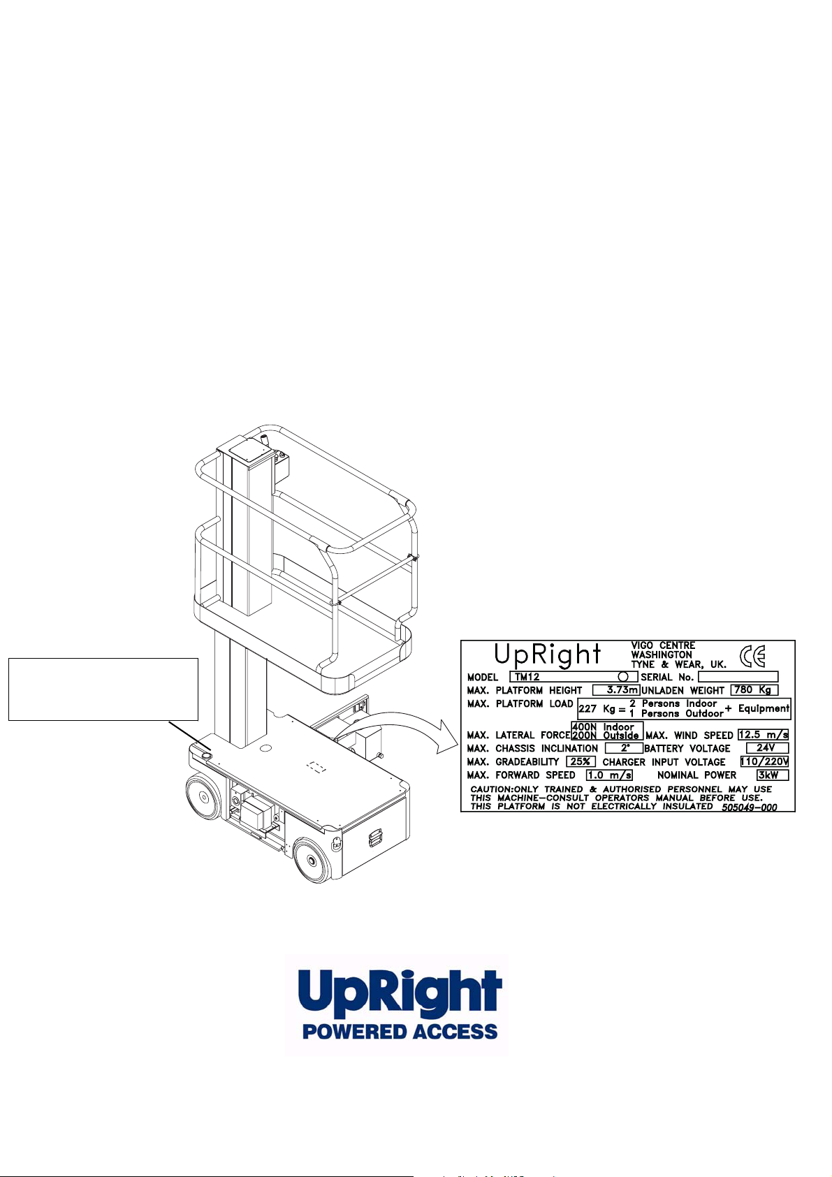
When contacting UpRight for service or parts information, be sure to include the MODEL and SERIAL NUMBERS from the
equipment nameplate. Should the nameplate be missing, the SERIAL NUMBER is also stamped on top of the chassis
above the front axle pivot.
Stamped Serial Number
Estampille de numéro de série
Eingestanzte Seriennummer
www.upright.com
Page 4

Page 5
OPERATION MANUAL
C
WARNING
All personnel shall carefully read, understand and follow all safety rules and operating instructions
before operating or performing maintenance on any UpRight Powered Access aerial work platform.
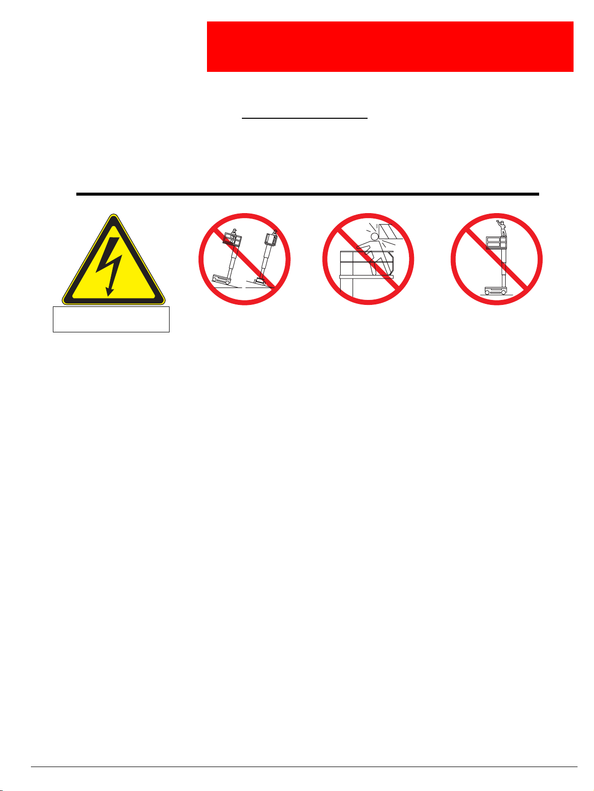
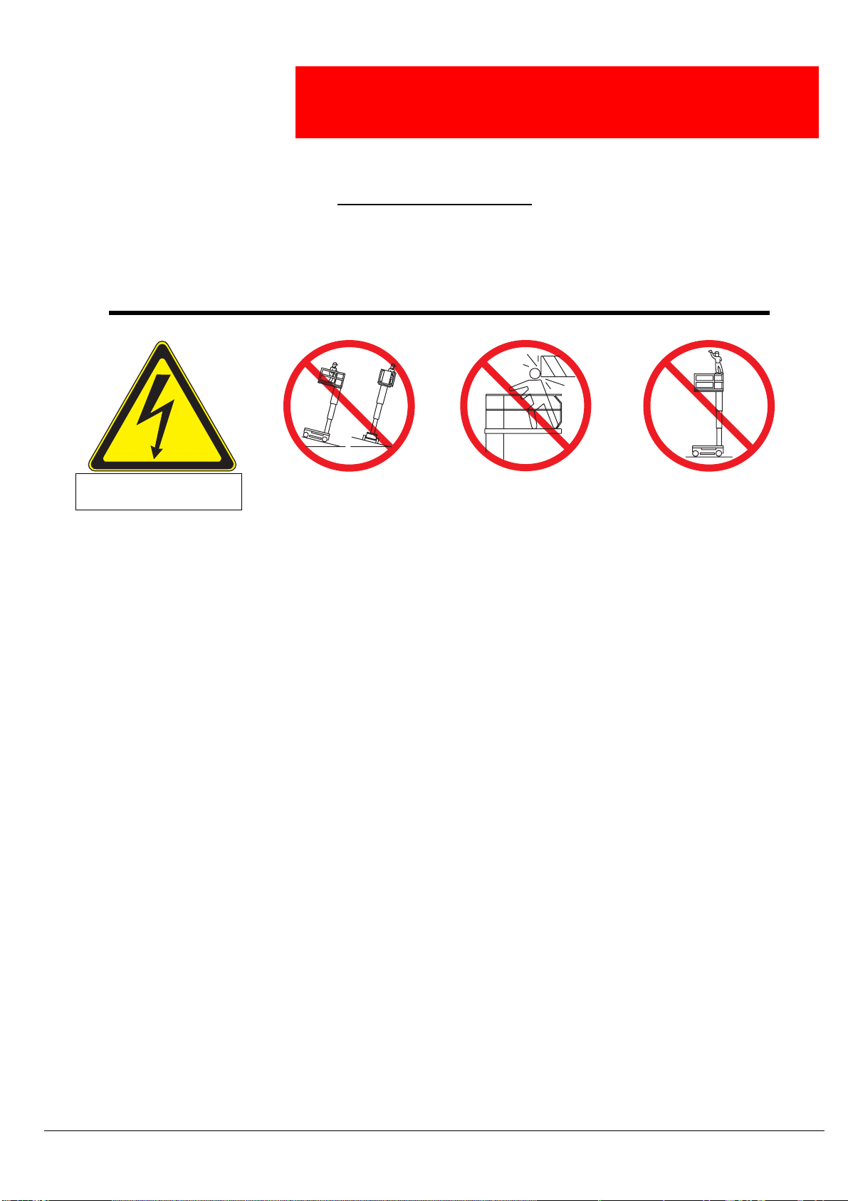
Safety Rules
Electrocution Hazard Tip Over Hazard
THIS MACHINE IS NOT
INSULATED!
USE OF THE AERIAL WORK PLATFORM: This aerial work platform is intended to lift persons and his tools as well as the material used
for the job. It is designed for repair and assembly jobs and assignments at overhead workplaces (ceilings, cranes, roof structures, buildings etc.). All other uses of the aerial work platform are prohibited!
THIS AERIAL WORK PLATFORM IS NOT INSULATED! For this reason it is imperative to keep a safe distance from live parts of electrical equipment!
Exceeding the specified permissible maximum load is prohibited! See “Platform Capacity” on page 4 for details.
The use and operation of the aerial work platform as a lifting tool or a crane is prohibited!
NEVER exceed the manual force allowed for this machine. See “Manual Force” on page 4 for details.
DISTRIBUTE all platform loads evenly on the platform.
NEVER operate the machine without first surveying the work area for surface hazards such as holes, drop-offs, bumps, curbs, or debris;
and avoiding them.
OPERATE machine only on surfaces capable of supporting wheel loads.
NEVER operate the machine when wind speeds exceed this machine’s wind rating. See “Beaufort Scale” on page 4 for details.
IN CASE OF EMERGENCY push EMERGENCY STOP switch to deactivate all powered functions.
IF ALARM SOUNDS while platform is elevated, STOP, carefully lower platform. Move machine to a firm, level surface.
Climbing up the railing of the platform, standing on or stepping from the platform onto buildings, steel or prefab concrete structures, etc.,
is prohibited!
Dismantling the entry gate or other railing components is prohibited! Always make certain that the entry gate is closed and securely
locked!
It is prohibited to keep the entry gate in an open position when the platform is raised!
To extend the height or the range by placing of ladders, scaffolds or similar devices on the platform is prohibited!
NEVER perform service on machine while platform is elevated without blocking elevating assembly.
INSPECT the machine thoroughly for cracked welds, loose or missing hardware, hydraulic leaks, loose wire connections, and damaged
cables or hoses before using.
VERIFY that all labels are in place and legible before using.
NEVER use a machine that is damaged, not functioning properly, or has damaged or missing labels.
To bypass any safety equipment is prohibited and presents a danger for the persons on the aerial work platform and in its working range.
NEVER charge batteries near sparks or open flame. Charging batteries emit explosive hydrogen gas.
Modifications to the aerial work platform are prohibited or permissible only at the approval by
AFTER USE, secure the work platform from unauthorized use by turning the keyswitch off and removing key.
NEVER elevate the platform or drive
the machine while elevated unless
the machine is on a firm, level
surface.
ollision Hazard Fall Hazard
NEVER position the platform
without first checking for overhead
obstructions or other hazards.
UpRight Powered Access.
NEVER climb, stand, or sit on
platform guardrails or midrail.
Operation Manual Page 1
Page 6

C
ONTENTS
Introduction . . . . . . . . . . . . . . . . . . . . . . . . . . . . . . . . . . . . . . . . . . . . . . . . . . . . . . . . . . . . . . . . . . . . . . . . . 3
General Description . . . . . . . . . . . . . . . . . . . . . . . . . . . . . . . . . . . . . . . . . . . . . . . . . . . . . . . . . . . . . . . . . . 3
Special Limitations . . . . . . . . . . . . . . . . . . . . . . . . . . . . . . . . . . . . . . . . . . . . . . . . . . . . . . . . . . . . . . . . . . . 4
Platform Capacity. . . . . . . . . . . . . . . . . . . . . . . . . . . . . . . . . . . . . . . . . . . . . . . . . . . . . . . . . . . . . . . . . . . . . . . . . . . . 4
Manual Force . . . . . . . . . . . . . . . . . . . . . . . . . . . . . . . . . . . . . . . . . . . . . . . . . . . . . . . . . . . . . . . . . . . . . . . . . . . . . . . 4
Beaufort Scale . . . . . . . . . . . . . . . . . . . . . . . . . . . . . . . . . . . . . . . . . . . . . . . . . . . . . . . . . . . . . . . . . . . . . . . . . . . . . . 4
Controls and Indicators . . . . . . . . . . . . . . . . . . . . . . . . . . . . . . . . . . . . . . . . . . . . . . . . . . . . . . . . . . . . . . . 5
Pre-Operation Safety Inspection . . . . . . . . . . . . . . . . . . . . . . . . . . . . . . . . . . . . . . . . . . . . . . . . . . . . . . . . 5
System Function Inspection . . . . . . . . . . . . . . . . . . . . . . . . . . . . . . . . . . . . . . . . . . . . . . . . . . . . . . . . . . . 6
Operation . . . . . . . . . . . . . . . . . . . . . . . . . . . . . . . . . . . . . . . . . . . . . . . . . . . . . . . . . . . . . . . . . . . . . . . . . . . 7
Travel With Platform Lowered . . . . . . . . . . . . . . . . . . . . . . . . . . . . . . . . . . . . . . . . . . . . . . . . . . . . . . . . . . . . . . . . . . 7
Steering . . . . . . . . . . . . . . . . . . . . . . . . . . . . . . . . . . . . . . . . . . . . . . . . . . . . . . . . . . . . . . . . . . . . . . . . . . . . . . . . . . . 7
Elevating Platform . . . . . . . . . . . . . . . . . . . . . . . . . . . . . . . . . . . . . . . . . . . . . . . . . . . . . . . . . . . . . . . . . . . . . . . . . . . 7
Travel With Platform Elevated . . . . . . . . . . . . . . . . . . . . . . . . . . . . . . . . . . . . . . . . . . . . . . . . . . . . . . . . . . . . . . . . . . 7
Lowering Platform . . . . . . . . . . . . . . . . . . . . . . . . . . . . . . . . . . . . . . . . . . . . . . . . . . . . . . . . . . . . . . . . . . . . . . . . . . . 7
Emergency Lowering . . . . . . . . . . . . . . . . . . . . . . . . . . . . . . . . . . . . . . . . . . . . . . . . . . . . . . . . . . . . . . . . . . . . . . . . . 8
Parking Brake Release. . . . . . . . . . . . . . . . . . . . . . . . . . . . . . . . . . . . . . . . . . . . . . . . . . . . . . . . . . . . . . . . . . . . . . . . 8
After Use Each Day . . . . . . . . . . . . . . . . . . . . . . . . . . . . . . . . . . . . . . . . . . . . . . . . . . . . . . . . . . . . . . . . . . . . . . . . . . 8
Transporting the Machine . . . . . . . . . . . . . . . . . . . . . . . . . . . . . . . . . . . . . . . . . . . . . . . . . . . . . . . . . . . . . 9
By Crane . . . . . . . . . . . . . . . . . . . . . . . . . . . . . . . . . . . . . . . . . . . . . . . . . . . . . . . . . . . . . . . . . . . . . . . . . . . . . . . . . . 9
By Forklift . . . . . . . . . . . . . . . . . . . . . . . . . . . . . . . . . . . . . . . . . . . . . . . . . . . . . . . . . . . . . . . . . . . . . . . . . . . . . . . . . . 9
By Truck . . . . . . . . . . . . . . . . . . . . . . . . . . . . . . . . . . . . . . . . . . . . . . . . . . . . . . . . . . . . . . . . . . . . . . . . . . . . . . . . . . . 9
Maintenance. . . . . . . . . . . . . . . . . . . . . . . . . . . . . . . . . . . . . . . . . . . . . . . . . . . . . . . . . . . . . . . . . . . . . . . . 10
Blocking the Elevating Assembly . . . . . . . . . . . . . . . . . . . . . . . . . . . . . . . . . . . . . . . . . . . . . . . . . . . . . . . . . . . . . . . 10
Installation. . . . . . . . . . . . . . . . . . . . . . . . . . . . . . . . . . . . . . . . . . . . . . . . . . . . . . . . . . . . . . . . . . . . . . . . . . . . . 10
Removal . . . . . . . . . . . . . . . . . . . . . . . . . . . . . . . . . . . . . . . . . . . . . . . . . . . . . . . . . . . . . . . . . . . . . . . . . . . . . . 10
Hydraulic Fluid . . . . . . . . . . . . . . . . . . . . . . . . . . . . . . . . . . . . . . . . . . . . . . . . . . . . . . . . . . . . . . . . . . . . . . . . . . . . . 10
Check Hydraulic Fluid . . . . . . . . . . . . . . . . . . . . . . . . . . . . . . . . . . . . . . . . . . . . . . . . . . . . . . . . . . . . . . . . . . . . 10
Battery Maintenance . . . . . . . . . . . . . . . . . . . . . . . . . . . . . . . . . . . . . . . . . . . . . . . . . . . . . . . . . . . . . . . . . . . . . . . . 11
Battery Charging . . . . . . . . . . . . . . . . . . . . . . . . . . . . . . . . . . . . . . . . . . . . . . . . . . . . . . . . . . . . . . . . . . . . . . . . 11
Inspection and Maintenance Schedule . . . . . . . . . . . . . . . . . . . . . . . . . . . . . . . . . . . . . . . . . . . . . . . . . . 12
Daily Preventative Maintenance Checklist . . . . . . . . . . . . . . . . . . . . . . . . . . . . . . . . . . . . . . . . . . . . . . . 13
Specifications . . . . . . . . . . . . . . . . . . . . . . . . . . . . . . . . . . . . . . . . . . . . . . . . . . . . . . . . . . . . . . . . . . . . . . 14
Page 2 Operation Manual
Page 7
I
NTRODUCTION
G
ENERAL
Introduction
This manual covers all models of the TM12 Aerial Work Platform. This manual must be stored on the
machine at all times.
Read, understand and follow all safety rules and operating instructions before attempting to operate the
machine.
D
ESCRIPTION
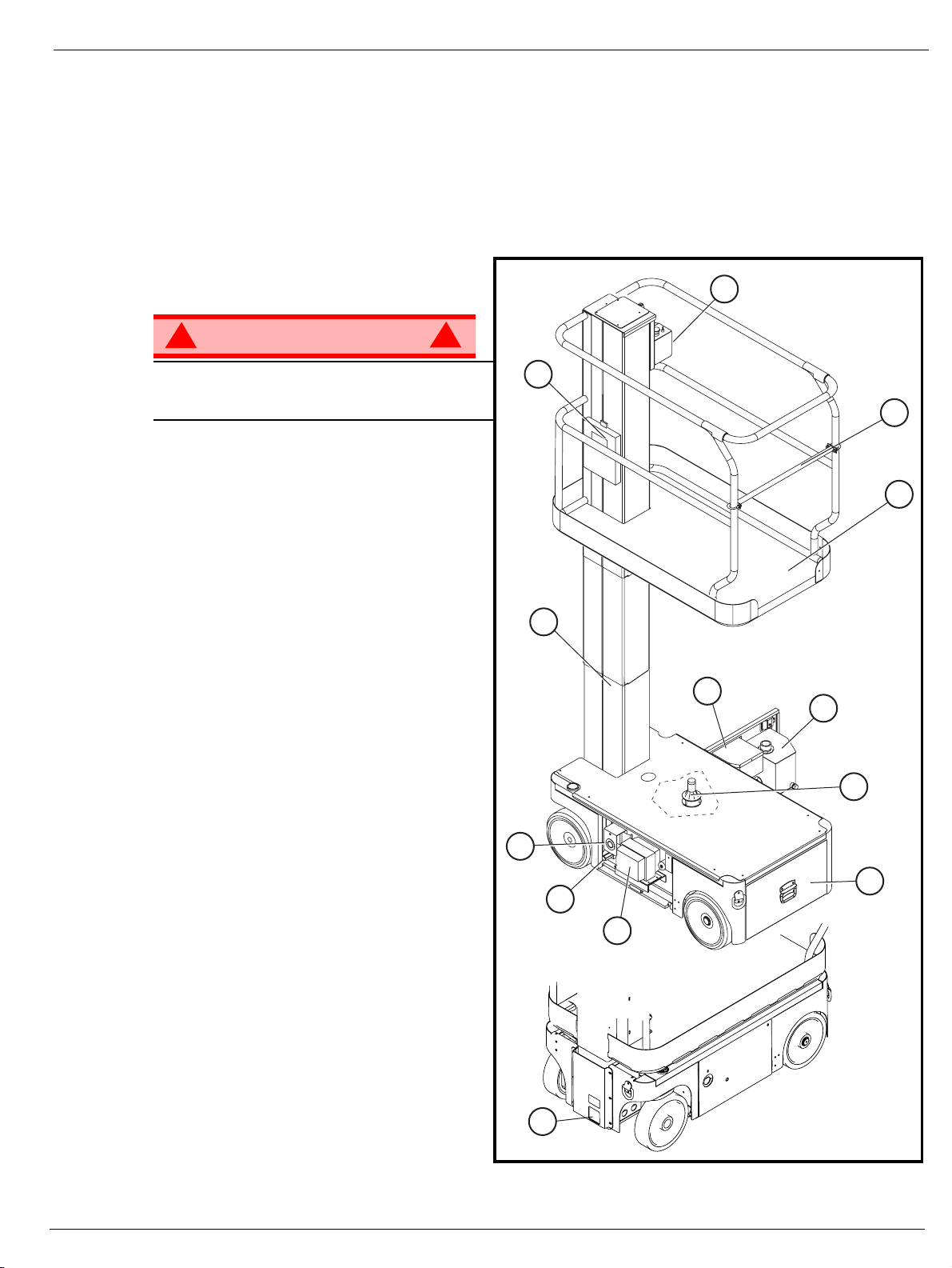
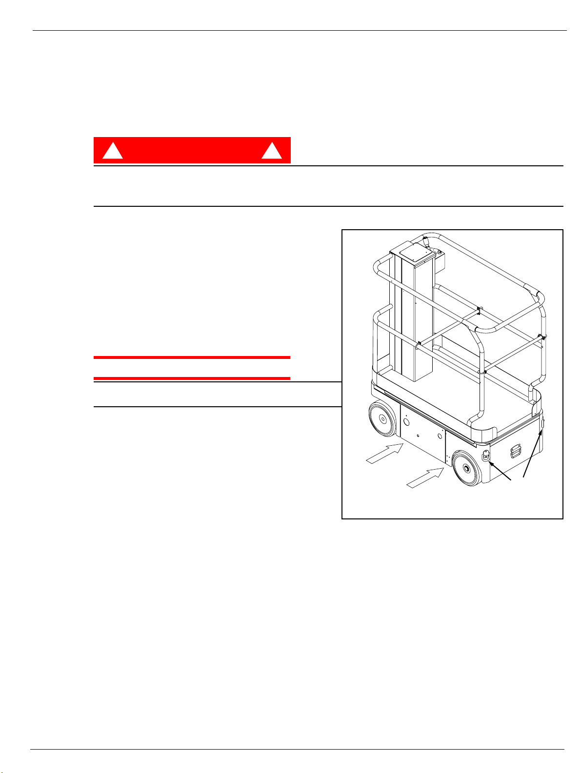
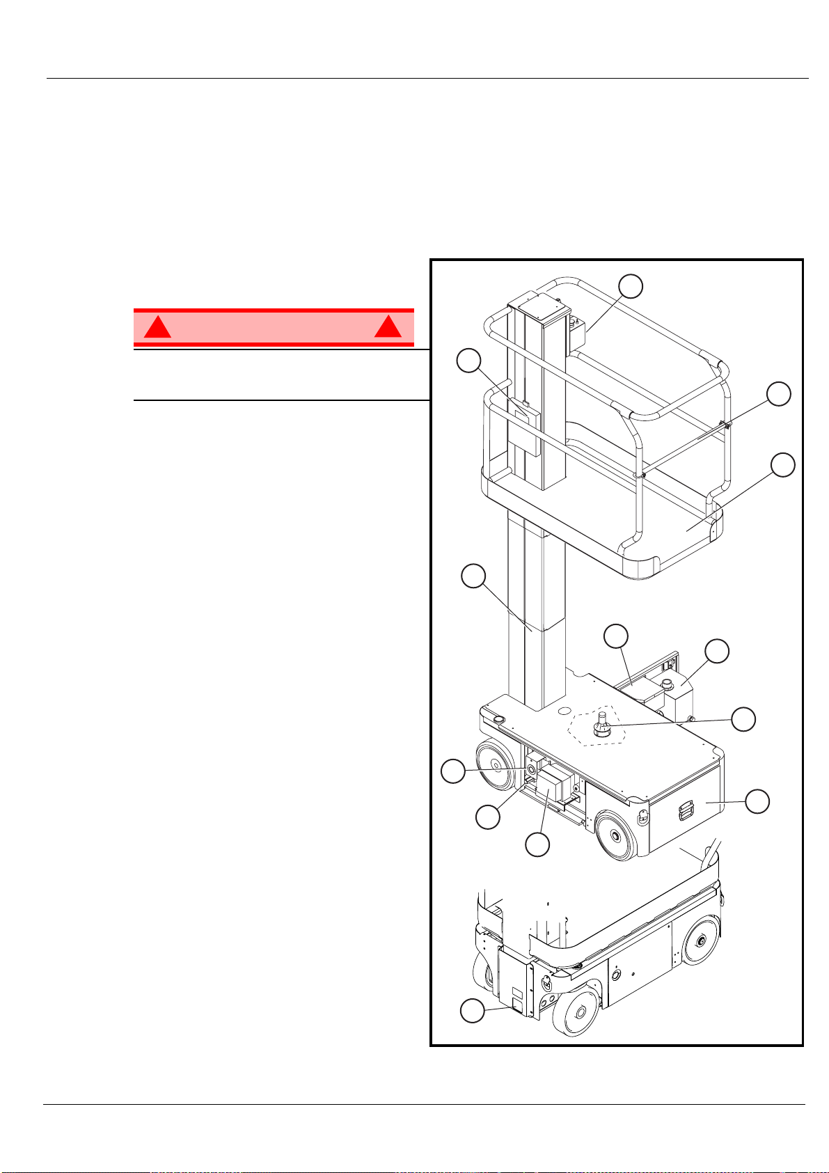
Figure 1: TM12 Series
1. Platform
4
!
WARNING
DO NOT use the maintenance platform
without guardrails properly assembled and
in place
2. Entry Bar
3. Elevating Mast
4. Platform Controls
5. Manual Case
6. Electrical Box
7. Hydraulic Reservoir
8. Level Sensor
9. Battery Tray
10. Emergency Lowering Valve
11. Battery Charger
12. Drive Relief Valve
13. Charger Outlet Plug
!
5
2
1
3
6
7
8
13
9
12
11
10
Operation Manual Page 3
Page 8
Special Limitations
S
PECIAL
Travel with the platform raised is limited to creep speed range.
Elevating the platform is limited to firm, level surfaces only.
The elevating function shall ONLY be used when the work platform is level and on a firm surface.
The work platform is NOT intended to be driven over uneven, rough, or soft terrain.
P
LATFO R M
The maximum platform capacity for the TM12 is 227 kg (500 lbs). Two people may occupy the platform
indoors, while only one may occupy the platform outdoors.
DO NOT exceed the maximum platform capacity or the platform occupancy limits for this machine.
M
Manual force is the force applied by the occupants to objects such as walls or other structures outside the
work platform.
L
IMITATIONS
D A N G E R
! !
C
APAC I T Y
D A N G E R
! !
ANUAL
F
ORCE
The maximum allowable manual force is limited to 200 N (45 lbs.) of force per occupant, with a maximum
of 400 N (90 lbs.) for two occupants.
D A N G E R
! !
DO NOT exceed the maximum amount of manual force for this machine.
B
EAUFO R T
Never operate the machine when wind speeds exceed 12.5m/s (28mph) [Beaufort scale 6].
BEAUFORT
RATING
3 3,4~5,4 12,25~19,4 11.5~17.75 7.5~12.0 Papers and thin branches move, flags wave.
4 5,4~8,0 19,4~28,8 17.75~26.25 12.0~18 Dust is raised, paper whirls up, and small branches sway.
5 8,0~10,8 28,8~38,9 26.25~35.5 18~24.25 Shrubs with leaves start swaying. Wave crests are apparent in ponds or swamps.
6 10,8~13,9 38,9~50,0 35.5~45.5 24.5~31 Tree branches move. Power lines whistle. It is difficult to open an umbrella.
7 13,9~17,2 50,0~61,9 45.5~56.5 31.~38.5 Whole trees sway. It is difficult to walk against the wind.
m/s km/h ft/s mph
S
WIND SPEED
CALE
GROUND CONDITIONS
Page 4 Operation Manual
Page 9
C
ONTROLS
Controls and Indicators
AND
The operator shall know the location of each control and indicator and have a thorough knowledge of the
function and operation of each before attempting to operate the unit.
I
NDICATORS
2
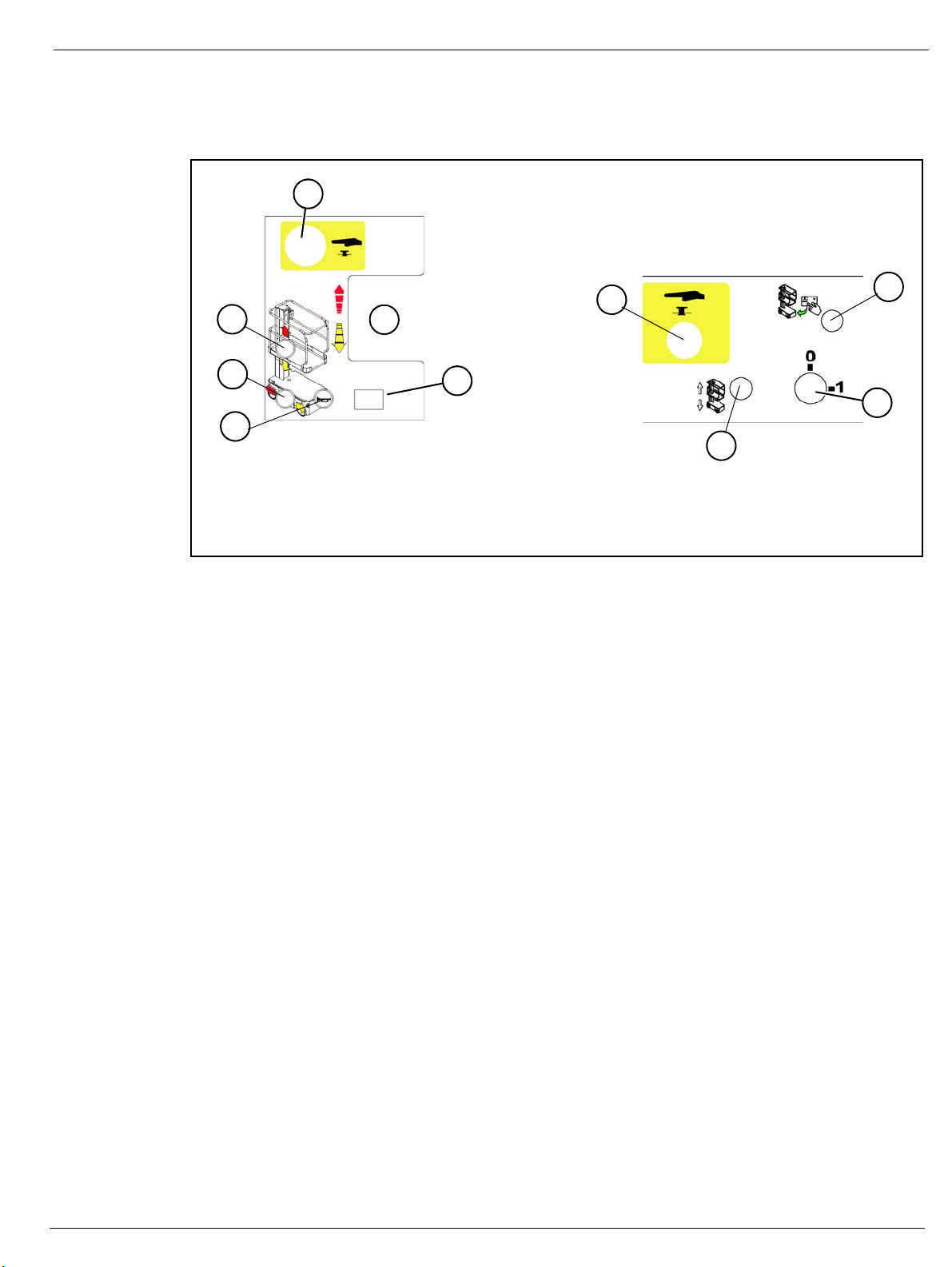
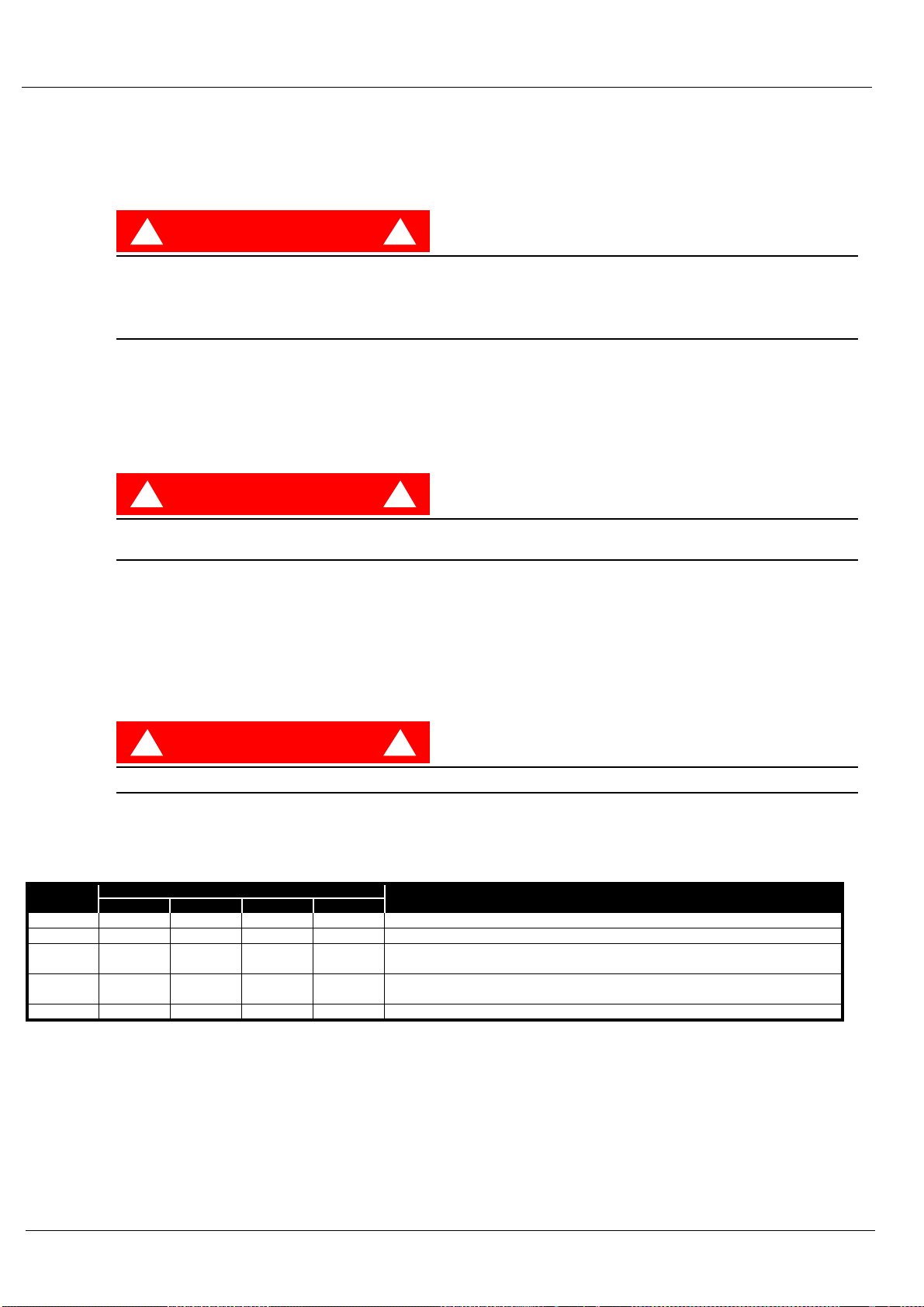
Figure 2: Controls and Indicators
Platform Controller
Chassis Controller (Right Side)
P
RE
5
3
4
1
10
9
Side View
1. Joystick
2. Emergency Stop
3. Lift Button
4. Drive Button
5. Emergency Stop (chassis)
-O
PERATION
NOTE: Carefully read, understand and follow all safety rules, operating instructions, labels and National Safety
Instructions/Requirements. Perform the following steps each day before use.
1. Open the Chassis Door and inspect for damage, fluid leaks or missing parts.
2. Check the level of the hydraulic fluid with the platform fully lowered. Open the Chassis Door and remove
the reservoir cap, fluid should be visible on the dipstick. Add recommended hydraulic fluid if necessary.
See “Specifications” on page 14.
3. Check that the fluid level in the batteries is correct. See “Battery Maintenance” on page 11.
4. Verify that the batteries are charged.
5. Check that the A.C. extension cord has been disconnected from the chassis outlet.
6. Check that all guardrails are in place and all fasteners are properly tightened.
7. Inspect the machine thoroughly for cracked welds and structural damage, loose or missing hardware,
hydraulic leaks, damaged control cable and loose wire connections.
S
AFETY
I
NSPECTION
Top View
6. Toggle switch (chassis)
7. Enable button
8. Keyswitch
9. Horn Button
10. Display
6
7
8
Operation Manual Page 5
Page 10
System Function Inspection
S
YSTEM
F
UNCTION
Refer to Figure 1 and Figure 2 for the locations of various controls and indicators.
I
NSPECTION
!
WARNING
STAND CLEAR of the work platform while performing the following checks.
Before operating the machine, survey the work area for surface hazards such as holes, drop-offs, bumps
and debris.
Check in ALL directions, including above the work platform, for obstructions and electrical conductors.
Protect the control console cable from possible damage while performing checks.
1. Move the machine, if necessary, to an unobstructed area to allow for full elevation.
2. Turn the Chassis and Platform Emergency Stop Switches ON by pulling the buttons out.
3. Turn the Chassis Key Switch to ON.
4. Push the Chassis Lift Switch to the UP position and fully elevate the platform.
5. Visually inspect the mast assembly for damage or erratic operation. Check for missing or loose parts.
6. Verify that the depression mechanism supports have rotated into position under the machine.
7. Check Level Sensor operation:
a. Open the door.
b. Push and hold the sensor off of level.
c. Push the Chassis Lift Switch to the UP
position.
• The alarm should sound, and the platform should not lift.
d. Close and latch the door.
8. Partially lower the platform by pushing the
Chassis Lift Switch to DOWN, and check the
operation of the audible lowering alarm.
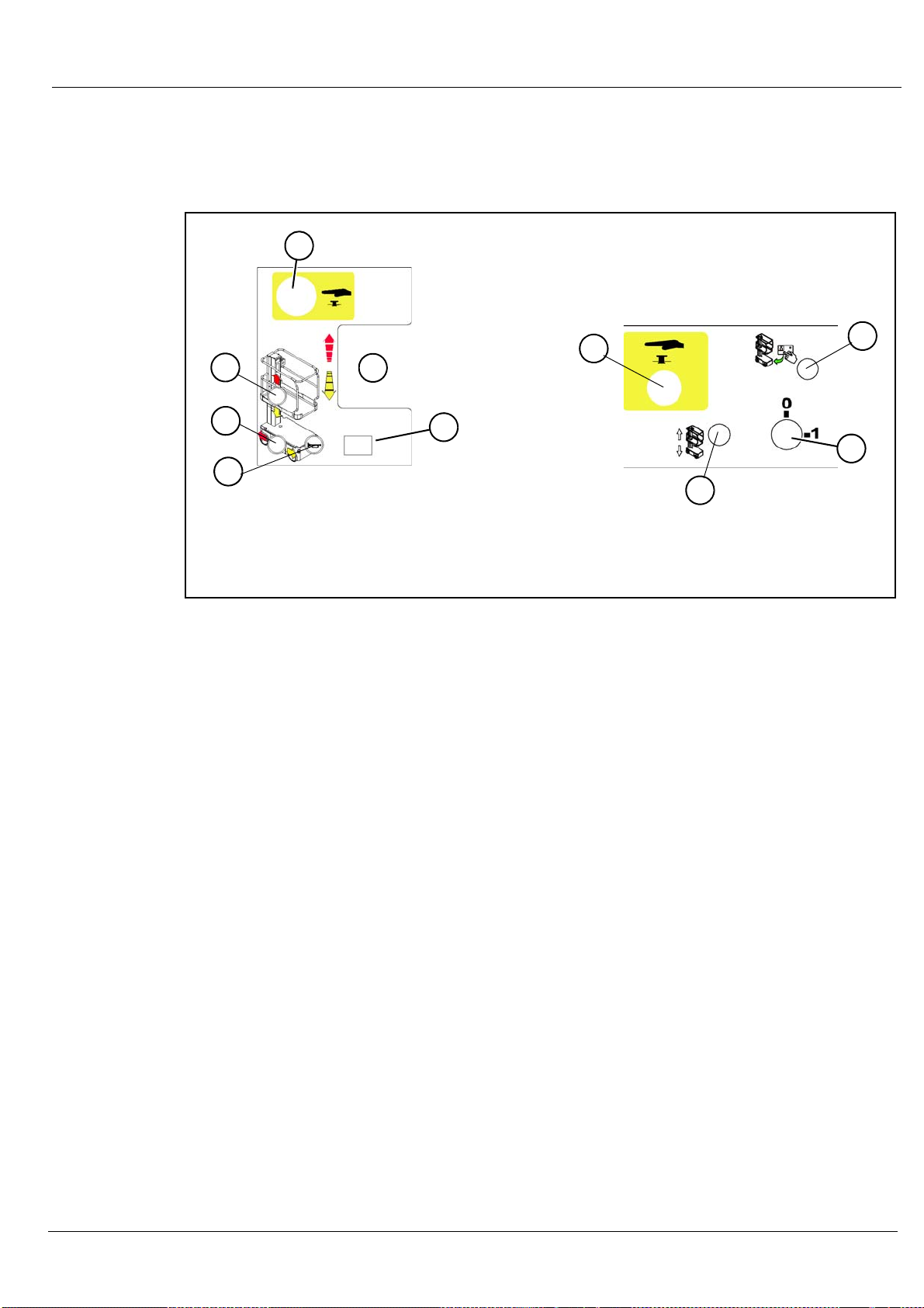
9. Check the Chassis Emergency Lowering
Valve for proper operation (see Figure 4):
a. Open the valve by pulling the knob out.
b. Once the platform is fully lowered, close the valve by releasing the knob.
10. Push the Chassis Emergency Stop Switch down to the OFF position. All machine functions should be
disabled. Pull out the Chassis Emergency Stop Switch to resume.
11. Mount the platform.
12. Check that the route is clear of persons, obstructions, holes and drop-offs, is level and capable of supporting the wheel loads.
13. After mounting platform, lower the bar across the entrance.
14. Select DRIVe mode.
15. While depressing the Interlock Switch, slowly position the Control Lever to FORWARD then REVERSE
to check for speed and directional control. The farther you push or pull the Control Lever from center the
faster the machine will travel.
16. Push the Steering Switch RIGHT then LEFT to check for steering control.
17. Push the Platform Emergency Stop Switch down to the OFF position. All machine functions should be
disabled. Pull out the Platform Emergency Stop Switch to resume.
!
Figure 3: Level Sensor Location
Level Sensor
Page 6 Operation Manual
Page 11

O
PERATION
Operation
Before operating the machine, ensure that the Pre-Operation Safety Inspection has been completed and
that any deficiencies have been corrected. Never operate a damaged or malfunctioning machine. The
operator must be thoroughly trained on this machine.
T
RAVEL
1. Check that the route is clear of people, obstructions, holes and drop-offs, is level and is capable of supporting wheel loads.
2. Verify that the Chassis Key Switch is turned to ON and the Chassis Emergency Stop Switch is ON, (pull
button out).
3. After mounting the platform, lower the bar across entrance.
4. Check clearances above, below and to the sides of the machine.
5. Pull the Controller Emergency Stop switch up to the ON position.
6. Select DRIVE mode.
7. While depressing the Interlock Switch, slowly push or pull the Control Lever to FORWARD or REVERSE
position to travel in the desired direction. The farther you push or pull the Control Lever from center the
faster the machine will travel.
S
TEERING
W
ITH
P
LATFORM
L
OWERED
NOTE: Steering is not self-centering. Wheels must be returned to straight ahead position by operating the Steering
Switch.
1. Select DRIVE mode.
2. While depressing the Interlock Switch, push the Steering Switch to RIGHT or LEFT to turn the wheels in
the desired direction. Observe the tires while maneuvering the machine to ensure proper direction.
E
LEVATING
1. Select LIFT mode.
2. While depressing the Interlock Switch, push Control Lever forward to UP, the farther you push the Control Lever the faster the Platform will elevate.
3. If the machine is not level the Tilt Alarm will sound and the machine will not lift or drive. If the Tilt alarm
sounds the platform must be lowered and the machine moved to a level location before attempting to reelevate the Platform.
T
RAVEL
NOTE: The machine will travel at reduced speed when the platform is elevated.
1. Check that the route is clear of persons, obstructions, holes and drop-offs, is level and capable of supporting the wheel loads.
2. Check clearances above, below and to the sides of the platform.
3. Select DRIVE mode.
4. While depressing the Interlock Switch, push Control Lever to FORWARD or REVERSE for desired direction of travel.
5. If the machine is not level the Tilt Alarm will sound and the machine will not lift or drive. If the Tilt alarm
sounds the platform must be lowered and the machine moved to a level location before attempting to reelevate the Platform.
W
P
ITH
LATFORM
P
LATFORM
E
LEVATED
L
OWERING
1. Select LIFT mode.
2. While depressing the Interlock Switch, pull back on the Control Lever.
Operation Manual Page 7
P
LATFORM
Page 12
Operation
E
MERGENCY
L
OWERING
!
WARNING
If the platform should fail to lower, NEVER climb down the elevating assembly.
Stand clear of the elevating assembly while operating the Emergency Lowering Valve Knob.
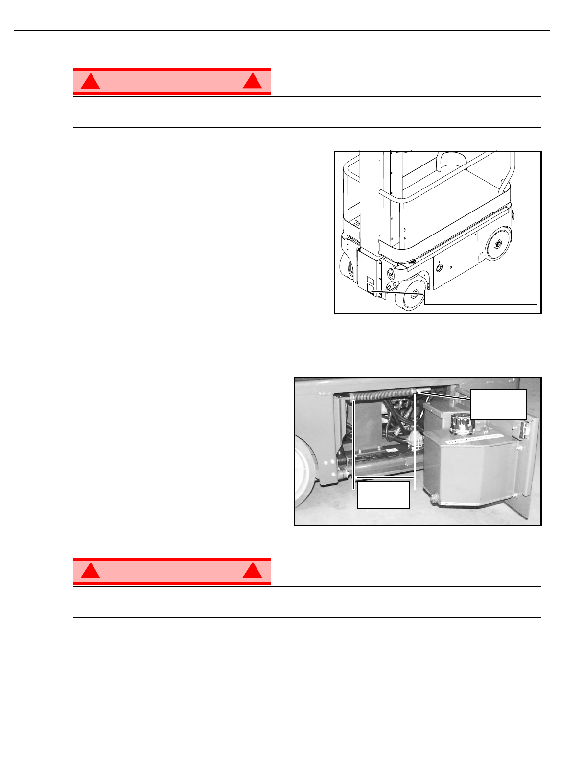
Ask a person on the ground to open the Emergency
Lowering Valve to lower the platform. The Emergency
Lowering Valve is located at the front of the chassis.
1. Open the Emergency Lowering Valve by pulling the
knob out.
2. To close, release the knob.
NOTE: The platform will not elevate if the Emergency Lowering
Valve is open.
P
ARKING
Perform the following procedure only when the machine will not operate under its own power and it is necessary to move the machine, or when winching onto a trailer to transport.
1. Remove the spring compression nut so the
spring is loose and the brake bars are away
from the tires.
2. The machine will now roll when pushed or
pulled.
B
RAKE
R
ELEASE
!
Figure 4: Emergency Lowering Valve
Emergency Lowering Valve
Figure 5: Parking Brake Release
Spring
Compression
Nut
After moving the machine and before normal
operation:
1. Replace the spring compression nut and
tighten until the spring measures 22,2-22,9
cm (8¾”-9”) in length, verify that the brake
bars have fully engaged the tires before the
machine is operated.
!
WARNING
Never tow faster than 0,3 m/sec. (1 ft./sec.).
Never operate the machine with the parking brakes released. Serious injury or damage could result.
A
FTER
1. Ensure that the platform is fully lowered.
2. Park the machine on a firm level surface, preferably under cover, secure against vandals, children and
3. Turn the Chassis Key Switch to OFF and remove the key to prevent unauthorized operation.
U
SE
E
ACH
unauthorized operation.
D
!
AY
22,2 cm to
22,9 cm”
Page 8 Operation Manual
Page 13
T
RANSPORTING
THE
M
Transporting the Machine
ACHINE
BY C
BY F
Forklifting is for transport only.
See specifications for weight of machine and be certain that forklift is of adequate capacity to lift the
machine.
BY T
1. Maneuver the machine into transport position and
2. Secure the machine to the transport vehicle with
RANE
Secure the straps to chassis lifting/tie down points only.
ORKLIFT
DANGER
! !
Forklift from the side by lifting under the Chassis.
RUCK
chock wheels.
chains or straps of adequate load capacity
attached to the chassis lifting/tie down points.
Figure 6: Transporting the Machine
CAUTION
Overtightening of the chains or straps attached to the
Tie Down lugs may result in damage to the machine
Forklift From
Side
Typical Tie Down/Lift Points
(D-Rings)
H
OUR
To access the hour meter function perform the following steps.
1. Climb into the basket (with the machine powered up)
2. Push the platform emergency stop button.
3. Hold down the following buttons, Horn and Lift.
4. While holding the buttons twist the emergency stop button to return power to the machine.
M
ETER
5. “hr” will now be displayed on the readout, Pressing the right turn button will scroll through the accumulated hours two digits at a time. For example, if pressing the right turn button once displays “20”, pressing
it a 2nd time displays “58”, and pressing it a 3rd time displays “hr”, the elapsed time of operation is 2058
hours.
Operation Manual Page 9
Page 14
Maintenance
M
AINTENANCE
!
WARNING
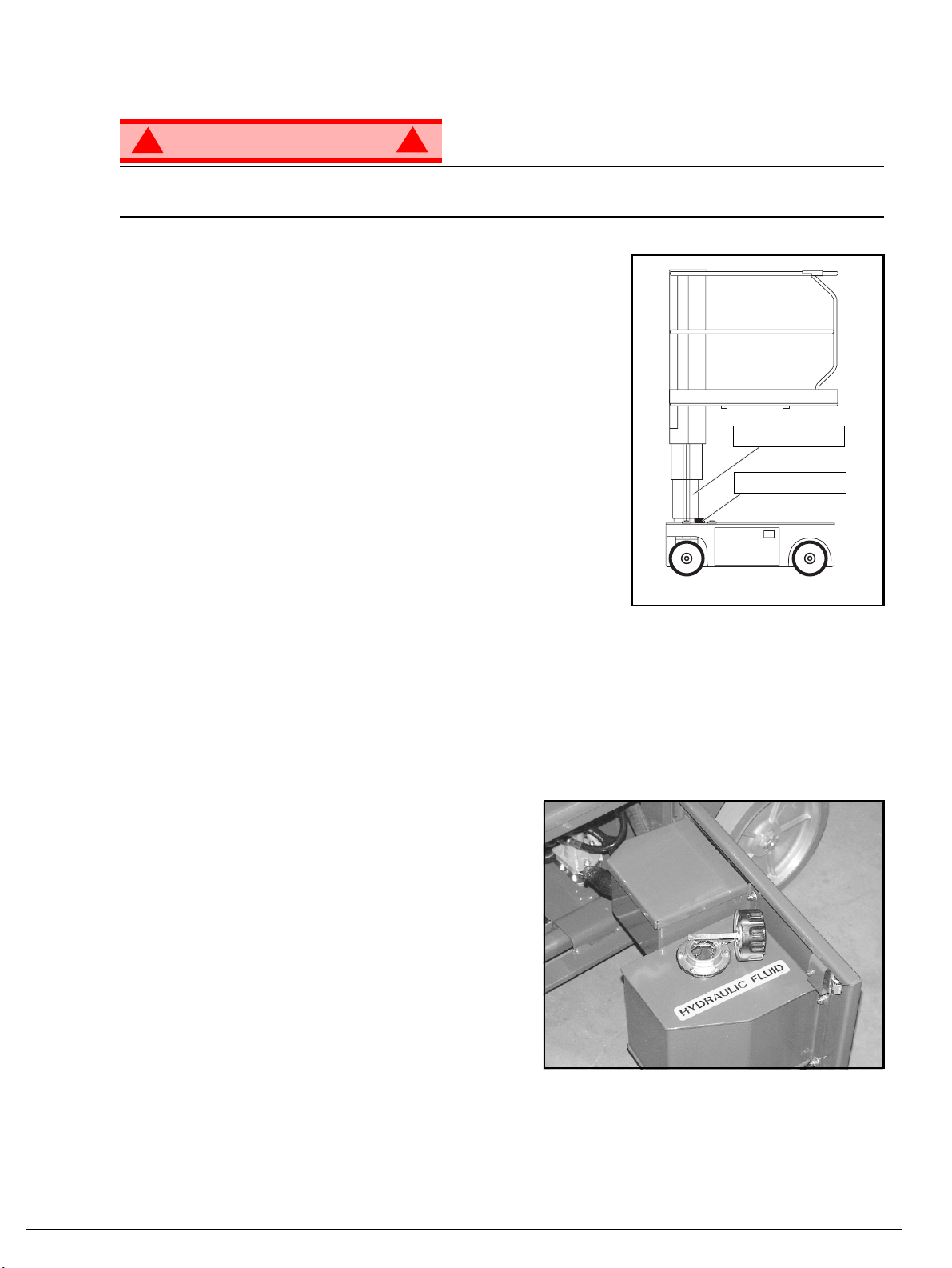
Never perform service while the platform is elevated without first blocking the elevating assembly.
DO NOT stand in the elevating assembly area while deploying or storing the brace.
B
LOCKING
I
NSTALLATION
1. Park the machine on firm level ground.
2. Verify that both Emergency Stop Switches are ON.
3. Turn and hold the Chassis Key Switch to CHASSIS.
4. Position the Chassis Lift Switch to UP and elevate the platform
approximately 1,2 m (4 ft.).
5. Place a solid wood block, 51mm x 100mm x 45cm (2”x 4”x18”)
between the second mast section and Chassis just behind the
mast assembly.
6. Push the Chassis Lift Switch to the DOWN position and gradually
lower the platform until the second mast section is supported by
the block.
R
EMOVAL
1. Push the Chassis Lift Switch to the UP position and gradually raise platform until the wood block can be
removed.
2. Remove the block.
3. Push the Chassis Lift Switch to the DOWN position and completely lower the platform.
THE
E
LEVATING
!
Figure 7: Supporting the Elevating Assembly
A
SSEMBLY
Number 2 Mast
Wood Block
H
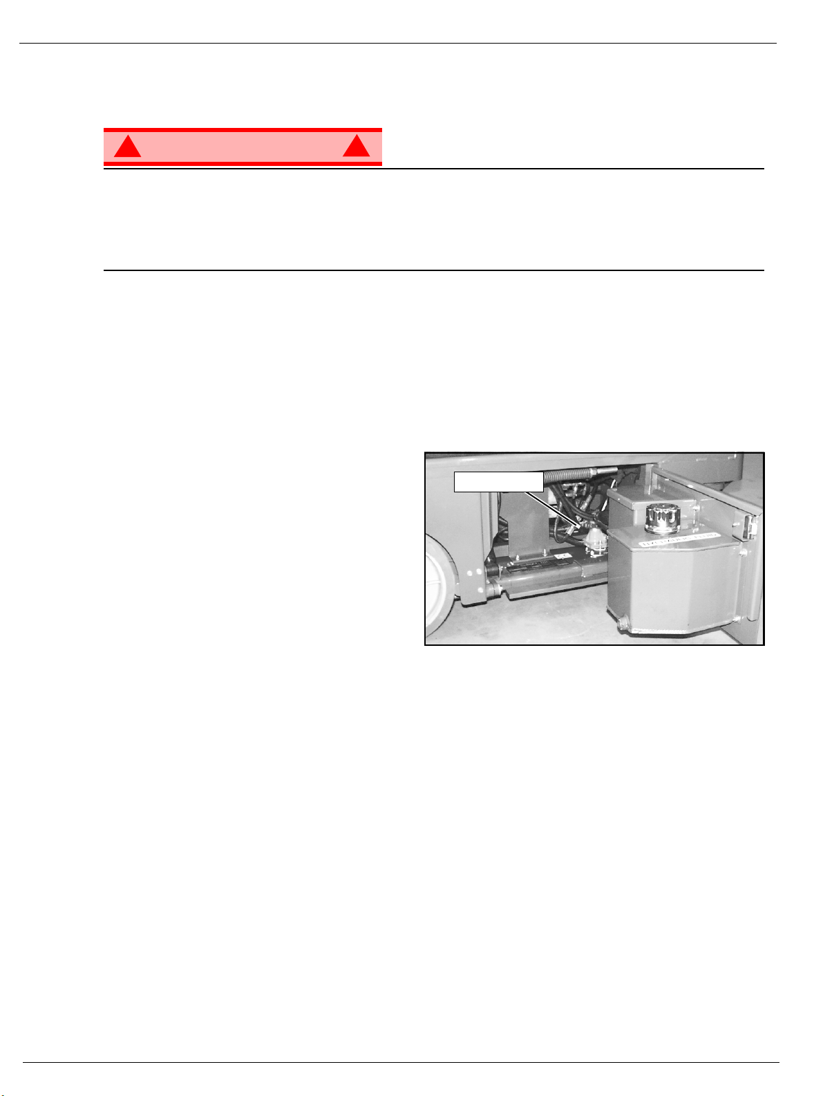
YDRAULIC
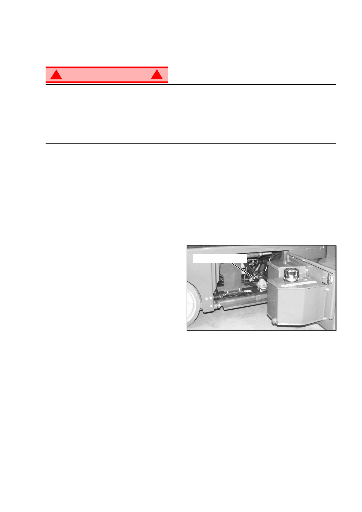
The hydraulic fluid reservoir is located in the chassis door.
NOTE: Never add fluid if the platform is elevated.
C
HECK HYDRAULIC FLUID
1. Make sure that the platform is fully lowered.
2. Open the chassis door.
3. Remove the filler cap from the hydraulic fluid reservoir.
4. Check the fluid level on the dipstick on the filler cap.
5. Add the appropriate fluid to bring the level to the
FULL mark. See “Specifications” on page 14
F
LUID
Figure 8: Hydraulic Fluid Reservoir and Dipstick
Page 10 Operation Manual
Page 15

B
ATTERY
M
AINTENANCE
Maintenance
Figure 9: Access to Batteries
!
WARNING
Hazard of explosive gas mixture. Keep sparks, flame, and smoking material
away from batteries.
Always wear safety glasses when working near batteries.
Battery fluid is highly corrosive. Thoroughly rinse away any spilled fluid with
clean water.
Always replace batteries with UpRight batteries or manufacturer approved
replacements weighing 26,3 kg (58 lbs.) each.
!
• Check the battery fluid level daily, especially if the machine is being used in a warm, dry climate.
• Keep the terminals and tops of the batteries clean.
• Refer to the Service Manual to extend battery life and for complete service instructions.
B
ATTERY CHARGING
Figure 10: Battery Charge Indicator
!
WARNING
Charge the batteries in a well ventilated area.
Do not charge the batteries when the machine is near a source of sparks or
flames.
Permanent damage to the batteries will result if the batteries are not immediately recharged after discharging.
Never leave the battery charger operating for more than two days.
Never disconnect the cables from the batteries when the charger is operating.
Keep the charger dry.
!
3
1. Check the battery fluid level. If the battery fluid level is lower than 10 mm (
only.
2. Connect an extension cord (1,5 mm² [12 gauge] minimum conductor diameter; 15 m (50 ft.) maximum length) to the
charger plug located at the left side of the chassis.
3. The charger turns on automatically after a short delay. Look through the charge indicator cutout to check the state of
charge.
• 0 - 50% charge:
• First Light -BLINKING-
• Second and Third Light -OFF-
• 50% - 75% Charge:
•First Light -ON-
• Second Light -BLINKING-
• Third Light -OFF-
• 75% - 100% Charge:
• First and Second Light -ON-
• Third Light - BLINKING-
• Charge Complete
• All Lights -ON-
• The charger automatically shuts down to low current after charging is complete and all lights turn ON.
• The charger continues at low current (equalizing charge) for 3-4 hours, then charging current shuts off completely.
4. Lights remain ON until the AC power supply is disconnected.
/8 in.) above the plates add distilled water
NOTE: The battery charger circuit must be used with a GFI (Ground Fault Interrupt) outlet.
NOTE: DO NOT operate the machine while the charger is plugged in.
Operation Manual Page 11
Page 16

Inspection and Maintenance Schedule
I
NSPECTION
The Complete Inspection consists of periodic visual and operational checks, along with periodic minor
adjustments that assure proper performance. Daily inspection will prevent abnormal wear and prolong the
life of all systems. The inspection and maintenance schedule should be performed at the specified intervals. Inspection and maintenance shall be performed by personnel who are trained and familiar with
mechanical and electrical procedures.
AND
M
AINTENANCE
S
CHEDULE
!
WARNING
Before performing preventative maintenance, familiarize yourself with the operation of the machine.
Always block the elevating assembly whenever it is necessary to perform maintenance while the
platform is elevated.
The daily preventative maintenance checklist has been designed for machine service and maintenance.
Please photocopy the Daily Preventative Maintenance Checklist and use the checklist when inspecting
the machine.
!
Page 12 Operation Manual
Page 17
D
AILY
M
AINTENANCE
P
REVENTATIVE
T
ABLE KEY
M
AINTENANCE
Daily Preventative Maintenance Checklist
C
HECKLIST
P
REVENTATIVE MAINTENANCE
R
EPORT
Y = Yes/Acceptable
N = No/Not Acceptable
R = Repaired/Acceptable
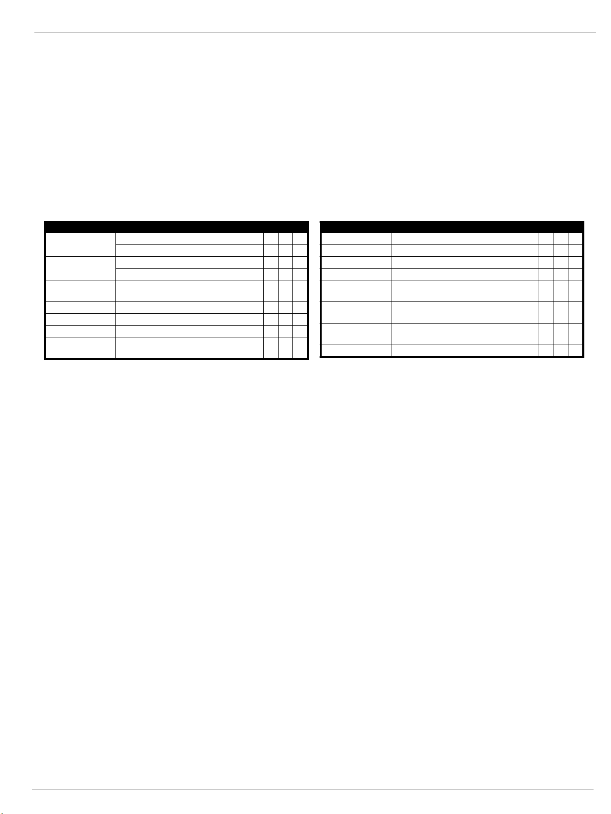
COMPONENT INSPECTION OR SERVICES Y N R
Battery
Chassis
Control Cable
Controller Check switch operation.
Drive Motors Check for operation and leaks.
Elevating Assembly Inspect for structural cracks.
Emergency Hydraulic
System
Check electrolyte level.
Check battery cable condition.
Check hoses for pinch or rubbing points.
Check welds for cracks.
Check the exterior of the cable for pinching,
binding or wear.
Operate the emergency lowering valve and
check for serviceability.
Date: _______________________________________
Owner:______________________________________
Model No: ___________________________________
Serial No:____________________________________
Serviced By: _________________________________
COMPONENT INSPECTION OR SERVICES Y N R
Entire Unit Check for and repair collision damage.
Hydraulic Fluid Check fluid level.
Hydraulic Pump Check for hose fitting leaks.
Hydraulic System Check for leaks.
Labels
Platform Deck and
Rails
Platform Deck and
Rails
Tires Check for damage.
Check for peeling, missing, or unreadable
labels & replace.
Check welds for cracks.
Check condition of deck.
Operation Manual Page 13
Page 18

Specifications
S
PECIFICATIONS
ITEM TM12
Platform Size 73,7 cm x 1,04 m (29 in. x 41 in.)
Maximum Platform Capacity 227 kg (500 lbs.)
Maximum Number of Occupants 2 People indoors/1 person outdoors
Height
Working Height
Maximum Platform Height
Minimum Platform Height
Dimensions
Weight
Overall Width
Overall Height
Overall Length
Drive Speed
Platform Lowered
Platform Raised
Energy Source 24V battery pack
Four 220 ampere hour, 6 Volt batteries, min. wt. 26,3 kg (58 lbs.) each
System Voltage 24 VDC
Battery Charger 20 AMP, 220 V AC 50Hz
Battery Duty Cycle 25% for 8 Hours
Hydraulic Reservoir Capacity 7,2 L (1.9 gal)
Maximum Hydraulic System Pressure 165 bar (2400 psi)
Hydraulic Fluid
Normal above 32° F [0° C]
Low Temp. below 32° F [0° C]
below 0° F [-17° C]
Lift System One Single Stage Lift Cylinder
Drive Control Proportional
Control System
Horizontal Drive Dual Front Wheel
Tires 30,5 cm (12 in.) diameter solid rubber, Non-marking
Parking Brakes Dual, Spring Applied, Hydraulic Release
Turning Radius 37 cm (14.5 in.) Inside
Maximum Gradeability 14º (25%)
Wheel Base 97,8 cm (38.5 in.)
Guardrails 1,10 m (43 in.)
Toeboard 152 mm (6 in.)
Noise Level
Proportional Control Handle with Interlock, Selector Switch,
Red Mushroom Emergency Stop Switches
5,83 m (19 ft.)
3,83 m (12.5 ft.)
48,3 cm (19 in.)
776 kg (1710 lbs.)
76 cm (30 in.)
165 cm (65 in.)
1,36 m (53.5 in.)
3,65 km/h (2.27 mph)
0,87 km/h (0.54 mph)
4 HP DC electric motor
ISO #46
ISO #32
ISO #15
*Specifications are subject to change without notice. Hot weather or heavy use may affect performance.
Refer to the Service Manual for complete parts and service information.
This machine meets or exceeds all applicable CE and GS machinery directive requirements.
Page 14 Operation Manual
Page 19

TM 12
Seriennummern 50211 – aktuell
DEUTSCH
Stellen Sie sicher, dass Sie die MODELL- und SERIENNUMMERN auf dem Gerätetypenschild angeben, wenn Sie sich
mit UpRight bezüglich Wartungs- oder Ersatzteilinformationen in Verbindung setzen. Sollte das Typenschild fehlen, finden
Sie die SERIENNUMMER auch auf dem Fahrwerk über der vorderen Schwenkachse.
Stamped Serial Number
Estampille de numéro de série
Eingestanzte Seriennummer
www.upright.com
Page 20

Page 21
BETRIEBSANLEITUNG
S
WARNUNG
Alle Bediener müssen die Sicherheitsregeln und Betriebsanleitungen gründlich durchlesen,
verstehen und befolgen, bevor sie an irgendeiner UpRight-Hocharbeitsbühne Wartungsarbeiten
ausführen oder die Arbeitsbühne in Betrieb nehmen.
Sicherheitsregeln
Elektroschockgefahr Kippgefahr Kollisionsgefahr
DIESE MASCHINE IST NICHT
EINSATZ DER HOCHARBEITSBÜHNE: Diese Hocharbeitsbühne dient dazu, Personen und Werkzeuge sowie die für die jeweilige Arbeit
erforderlichen Materialien zu transportieren. Sie wurde speziell für Reparatur- und Montagearbeiten sowie für Einsatzbereiche konzipiert, die sich
oberhalb der Mitarbeiter befinden, sodass die Mitarbeiter nach oben gerichtet arbeiten müssen (z. B. Decken, Kräne, Dachstrukturen, Gebäude
etc.). Jede andere Verwendung der Hocharbeitsbühne ist strikt verboten!
DIESE HOCHARBEITSBÜHNE IST NICHT ISOLIERT! Aus diesem Grund muss zwingend ein Sicherheitsabstand zu allen leitfähigen Teilen der
elektrischen Ausrüstung eingehalten werden!
Die angegebene zulässige Höchstlast darf nicht überschritten werden!Nähere Informationen hierzu finden Sie im Abschnitt “Tragfähigkeit der
Plattform” auf Seite 4.
Es ist strikt verboten, die Hocharbeitsbühne als Hubwerkzeug oder Kran einzusetzen!
Die für diese Maschine zulässige manuelle Kraft NIEMALS überschreiten.Nähere Informationen hierzu finden Sie im Abschnitt “Manuelle Kraft”
auf Seite 4.
Lasten immer gleichmäßig auf der Plattform VERTEILEN.
Vor Inbetriebnahme der Maschine IMMER ZUERST die Aufstellfläche im Arbeitsbereich auf Gefahren wie Bodenlöcher, ausgelaufene
Flüssigkeiten, Bodenerhebungen, Kanten oder Schutt untersuchen und diese umgehen bzw. beseitigen.
Maschine nur auf Oberflächen IN BETRIEB NEHMEN, die die zulässigen Radlasten aufnehmen können.
Maschine NIEMALS in Betrieb nehmen, wenn die tatsächliche Windgeschwindigkeit höher ist als die Windgeschwindigkeit, für die die Maschine
ausgelegt ist. Nähere Informationen hierzu finden Sie im Abschnitt “Beaufort-Skala” auf Seite 4.
IM NOTFALL NOT-AUS-Schalter drücken, um alle strombetriebenen Funktionen zu deaktivieren.
WENN EIN ALARM ERTÖNT, während die Plattform ausgefahren wird, Plattform ANHALTEN und vorsichtig einfahren (absenken). Maschine auf
feste, ebene Oberfläche fahren.
Auf das Schutzgeländer der Plattform zu klettern, auf Gebäuden, Stahl- oder vorgefertigten Betonstrukturen zu stehen oder von der Plattform aus
darauf zu klettern etc. ist verboten!
Die Geländerpforte oder andere Komponenten des Schutzgeländers zu demontieren ist verboten! Vergewissern Sie sich immer, dass die
Geländerpforte geschlossen und sicher verriegelt ist!
Es ist verboten, die Plattform bei geöffneter Geländerpforte auszufahren!
Die Höhe oder Reichweite der Plattform durch Anbringen von Leitern, Gerüsten oder ähnlichen Vorrichtungen zu vergrößern ist verboten!
IMMER ZUERST die Hubvorrichtung blockieren, bevor bei ausgefahrener Plattform Wartungs- oder Instandhaltungsarbeiten an der Maschine
durchgeführt werden.
Maschine vor jedem Gebrauch sorgfältig auf Risse an Schweißstellen, lose oder fehlende Beschläge, Leckagen in der Hydraulikvorrichtung,
gelöste Kabelverbindungen und beschädigte Kabel oder Schläuche UNTERSUCHEN.
Vor Gebrauch SICHERSTELLEN, dass alle Bezeichnungsschilder ordnungsgemäß angebracht und vollständig lesbar sind.
NIEMALS eine Maschine benutzen, die beschädigt ist, nicht ordnungsgemäß funktioniert oder deren Bezeichnungsschilder Beschädigungen
aufweisen oder sogar ganz fehlen.
Sicherheitseinrichtungen zu umgehen ist verboten und stellt eine Gefahr für alle Personen dar, die sich auf der Hocharbeitsbühne und in deren
Arbeitsbereich befinden.
Batterien NIEMALS in der Nähe von Funkenquellen oder offenen Flammen aufladen. Beim Aufladen von Batterien wird explosives
Wasserstoff
Änderungen an der Hocharbeitsbühne sind verboten bzw. nur mit ausdrücklicher Genehmigung von
NACH GEBRAUCH ist die Arbeitsplattform gegen unbefugten Gebrauch durch Dritte zu sichern. Hierzu muss der Schlüsselschalter auf “Aus”
gestellt und der Schlüssel abgezogen werden.
ISOLIERT!
-gas freigesetzt.
NIEMALS
oder die Maschine mit ausgefahrener
Plattform fortbewegen, wenn sich die
Maschine nicht auf einer festen,
die Plattform ausfahren
ebenen Fläche befindet.
Plattform
bringen, ohne vorher sicherzustellen,
dass der Bereich über der Plattform
frei von Hindernissen und anderen
NIEMALS
Gefahren ist.
in Position
UpRight zulässig.
NIEMALS auf das obere oder
turzgefahr
mittlere Gestänge des
Plattformgeländers klettern
und auch nicht darauf stehen
oder sitzen.
Betriebsanleitung Seite 1
Page 22

I
NHALT
Einführung . . . . . . . . . . . . . . . . . . . . . . . . . . . . . . . . . . . . . . . . . . . . . . . . . . . . . . . . . . . . . . . . . . . . . . . . . . 3
Allgemeine Beschreibung . . . . . . . . . . . . . . . . . . . . . . . . . . . . . . . . . . . . . . . . . . . . . . . . . . . . . . . . . . . . . 3
Beschränkungen . . . . . . . . . . . . . . . . . . . . . . . . . . . . . . . . . . . . . . . . . . . . . . . . . . . . . . . . . . . . . . . . . . . . . 4
Tragfähigkeit der Plattform. . . . . . . . . . . . . . . . . . . . . . . . . . . . . . . . . . . . . . . . . . . . . . . . . . . . . . . . . . . . . . . . . . . . . 4
Manuelle Kraft . . . . . . . . . . . . . . . . . . . . . . . . . . . . . . . . . . . . . . . . . . . . . . . . . . . . . . . . . . . . . . . . . . . . . . . . . . . . . . 4
Beaufort-Skala . . . . . . . . . . . . . . . . . . . . . . . . . . . . . . . . . . . . . . . . . . . . . . . . . . . . . . . . . . . . . . . . . . . . . . . . . . . . . . 4
Bedienelemente und Anzeigen . . . . . . . . . . . . . . . . . . . . . . . . . . . . . . . . . . . . . . . . . . . . . . . . . . . . . . . . . 5
Sicherheitsprüfung vor Inbetriebnahme . . . . . . . . . . . . . . . . . . . . . . . . . . . . . . . . . . . . . . . . . . . . . . . . . . 5
Überprüfung der Systemfunktionen . . . . . . . . . . . . . . . . . . . . . . . . . . . . . . . . . . . . . . . . . . . . . . . . . . . . . 6
Bedienung . . . . . . . . . . . . . . . . . . . . . . . . . . . . . . . . . . . . . . . . . . . . . . . . . . . . . . . . . . . . . . . . . . . . . . . . . . 7
Fahren mit eingefahrener Plattform . . . . . . . . . . . . . . . . . . . . . . . . . . . . . . . . . . . . . . . . . . . . . . . . . . . . . . . . . . . . . . 7
Lenken . . . . . . . . . . . . . . . . . . . . . . . . . . . . . . . . . . . . . . . . . . . . . . . . . . . . . . . . . . . . . . . . . . . . . . . . . . . . . . . . . . . . 7
Ausfahren der Plattform . . . . . . . . . . . . . . . . . . . . . . . . . . . . . . . . . . . . . . . . . . . . . . . . . . . . . . . . . . . . . . . . . . . . . . . 7
Fahren mit ausgefahrener Plattform. . . . . . . . . . . . . . . . . . . . . . . . . . . . . . . . . . . . . . . . . . . . . . . . . . . . . . . . . . . . . . 7
Einfahren der Plattform . . . . . . . . . . . . . . . . . . . . . . . . . . . . . . . . . . . . . . . . . . . . . . . . . . . . . . . . . . . . . . . . . . . . . . . 7
Notfallabsenkung . . . . . . . . . . . . . . . . . . . . . . . . . . . . . . . . . . . . . . . . . . . . . . . . . . . . . . . . . . . . . . . . . . . . . . . . . . . . 8
Lösen der Parkbremse. . . . . . . . . . . . . . . . . . . . . . . . . . . . . . . . . . . . . . . . . . . . . . . . . . . . . . . . . . . . . . . . . . . . . . . . 8
Nach dem täglichen Gebrauch. . . . . . . . . . . . . . . . . . . . . . . . . . . . . . . . . . . . . . . . . . . . . . . . . . . . . . . . . . . . . . . . . . 8
Transport der Maschine . . . . . . . . . . . . . . . . . . . . . . . . . . . . . . . . . . . . . . . . . . . . . . . . . . . . . . . . . . . . . . . 9
Per Kran . . . . . . . . . . . . . . . . . . . . . . . . . . . . . . . . . . . . . . . . . . . . . . . . . . . . . . . . . . . . . . . . . . . . . . . . . . . . . . . . . . . 9
Per Gabelstapler . . . . . . . . . . . . . . . . . . . . . . . . . . . . . . . . . . . . . . . . . . . . . . . . . . . . . . . . . . . . . . . . . . . . . . . . . . . . 9
Per Lkw . . . . . . . . . . . . . . . . . . . . . . . . . . . . . . . . . . . . . . . . . . . . . . . . . . . . . . . . . . . . . . . . . . . . . . . . . . . . . . . . . . . 9
Instandhaltung. . . . . . . . . . . . . . . . . . . . . . . . . . . . . . . . . . . . . . . . . . . . . . . . . . . . . . . . . . . . . . . . . . . . . . 10
Blockieren der Hubvorrichtung. . . . . . . . . . . . . . . . . . . . . . . . . . . . . . . . . . . . . . . . . . . . . . . . . . . . . . . . . . . . . . . . . 10
Installation. . . . . . . . . . . . . . . . . . . . . . . . . . . . . . . . . . . . . . . . . . . . . . . . . . . . . . . . . . . . . . . . . . . . . . . . . . . . . 10
Entfernen. . . . . . . . . . . . . . . . . . . . . . . . . . . . . . . . . . . . . . . . . . . . . . . . . . . . . . . . . . . . . . . . . . . . . . . . . . . . . . 10
Hydraulikflüssigkeit. . . . . . . . . . . . . . . . . . . . . . . . . . . . . . . . . . . . . . . . . . . . . . . . . . . . . . . . . . . . . . . . . . . . . . . . . . 10
Überprüfen der Hydraulikflüssigkeit . . . . . . . . . . . . . . . . . . . . . . . . . . . . . . . . . . . . . . . . . . . . . . . . . . . . . . . . . 10
Instandhaltung der Batterie . . . . . . . . . . . . . . . . . . . . . . . . . . . . . . . . . . . . . . . . . . . . . . . . . . . . . . . . . . . . . . . . . . . 11
Aufladen der Batterien . . . . . . . . . . . . . . . . . . . . . . . . . . . . . . . . . . . . . . . . . . . . . . . . . . . . . . . . . . . . . . . . . . . 11
Inspektions- und Instandhaltungsplan . . . . . . . . . . . . . . . . . . . . . . . . . . . . . . . . . . . . . . . . . . . . . . . . . . 12
Checkliste der täglichen präventiven Instandhaltungsmaßnahmen . . . . . . . . . . . . . . . . . . . . . . . . . . 13
Technische Daten . . . . . . . . . . . . . . . . . . . . . . . . . . . . . . . . . . . . . . . . . . . . . . . . . . . . . . . . . . . . . . . . . . . 14
Seite 2 Betriebsanleitung
Page 23
E
INFÜHRUNG
A
LLGEMEINE
Einführung
Dieses Handbuch beschreibt die Bedienung aller Modelle von Hocharbeitsbühnen der Serie TM12.
Das Handbuch muss immer bei der Maschine aufbewahrt werden.
Stellen Sie sicher, dass Sie alle Sicherheitsregeln und Betriebsanleitungen durchlesen, verstehen
und befolgen, bevor Sie die Maschine in Betrieb nehmen.
B
ESCHREIBUNG
Abbildung 1: Serie TM12
1. Plattform
4
!
WARNUNG
Hocharbeitsbühne NICHT ohne korrekt
montiertes und angebrachtes
Schutzgeländer verwenden.
2. Eingangsschranke
3. Hubmast
4. Plattform-Bedienelemente
5. Handbuchfach
6. Schaltschrank
7. Hydraulikbehälter
8. Nivellierungssensor
9. Batteriefach
10. Ventil zur Notfallabsenkung
11. Batterieladegerät
12. Antriebsentlastungsventil
13. Anschluss Ladegerät
!
5
2
1
3
6
7
8
13
9
12
11
10
Betriebsanleitung Seite 3
Page 24
Beschränkungen
B
ESCHRÄNKUNGEN
Bei ausgefahrener Plattform kann die Maschine nur im Schleichgang gefahren werden.
Die Plattform kann nur auf festen, ebenen Oberflächen ausgefahren werden.
Die Hubfunktion darf NUR verwendet werden, wenn die Hocharbeitsbühne nivelliert ist und auf einer
festen Oberfläche steht.
Die Hocharbeitsbühne ist NICHT dafür ausgelegt, auf unebenem, grobem oder weichem Gelände
gefahren zu werden.
T
RAGFÄHIGKEIT
Die Plattform der TM12 hat eine maximale Tragfähigkeit von 227 kg (500 lbs). Im Innenbereich können
zwei Personen gleichzeitig auf der Arbeitsplattform stehen, während im Außenbereich nur eine Person
darauf stehen darf.
GEFAHR
! !
DER
GEFAHR
! !
P
LATTFORM
Maximale Tragfähigkeit der Plattform oder maximal zulässige Personenzahl für diese Maschine NICHT
überschreiten.
M
ANUELLE
Unter manueller Kraft versteht man die Kraft, die die Personen auf der Plattform auf Objekte wie Wände
oder andere Strukturen außerhalb der Arbeitsplattform ausüben.
Die maximal zulässige manuelle Kraft ist auf 200 N (45 lbs.) pro Person beschränkt, d. h. maximal 400 N
(90 lbs.), wenn sich zwei Personen auf der Plattform befinden.
GEFAHR
! !
Die für diese Maschine maximal zulässige manuelle Kraft NICHT überschreiten.
B
EAUFORT
Niemals die Maschine in Betrieb nehmen, wenn die Windgeschwindigkeit mehr als 12.5m/s (28 mph)
[Beaufort-Skala 6] beträgt.
BEAUFORT-
WERT
3 3,4~5,4 12,25~19,4 11.5~17.75 7.5~12.0 Papier und dünne Zweige bewegen sich, Fahnen wehen.
4 5,4~8,0 19,4~28,8 17.75~26.25 12.0~18 Staub und Papier wird aufgewirbelt und kleine Zweige schaukeln.
5 8,0~10,8 28,8~38,9 26.25~35.5 18~24.25
6 10,8~13,9 38,9~50,0 35.5~45.5 24.5~31
7 13,9~17,2 50,0~61,9 45.5~56.5 31.~38.5 Ganze Bäume schwanken. Es ist schwierig, gegen den Wind zu gehen.
m/s km/h ft/s mph
WINDGESCHWINDIGKEIT
K
-S
RAFT
KALA
BODEN-/UMGEBUNGSBEDINGUNGEN
Sträucher mit Blättern beginnen zu schaukeln. In Teichen, Sümpfen oder anderen Gewässern
erscheinen Wellenkämme.
Zweige und Äste von Bäumen bewegen sich. Stromleitungen pfeifen. Regenschirme können nur mit
Mühe geöffnet werden.
Seite 4 Betriebsanleitung
Page 25
B
EDIENELEMENTE
Vor Inbetriebnahme der Maschine muss sichergestellt sein, dass der Bediener die Position jedes
Bedienelementes und jeder Anzeige kennt und mit Funktionsweise und Bedienung der Maschine
umfassend vertraut ist.
UND
2
A
Plattform-Steuerung
Bedienelemente und Anzeigen
NZEIGEN
Abbildung 2: Bedienelemente und Anzeigen
Fahrwerk-Steuerung (rechte Seite)
S
ICHERHEITSPRÜFUNG
HINWEIS: Lesen Sie sich alle Sicherheitsregeln, Betriebsanleitungen, Bezeichnungsschilder und nationalen
Sicherheitsanweisungen/-anforderungen sorgfältig durch, stellen Sie sicher, dass Sie sie vollständig verstanden
haben und halten Sie sie ein. Gehen Sie jeden Tag vor Inbetriebnahme der Maschine wie folgt vor.
1. Öffnen Sie die Fahrwerktür, und prüfen Sie, ob Beschädigungen oder Leckagen (Flüssigkeitsaustritt)
vorhanden sind und ob Teile fehlen.
2. Überprüfen Sie bei vollständig abgesenkter Plattform die Füllstandshöhe der Hydraulikflüssigkeit.
Öffnen Sie die Fahrwerktür, und nehmen Sie die Kappe des Hydraulikbehälters ab. Die Flüssigkeit sollte
am Pegelstab sichtbar sein. Füllen Sie bei Bedarf etwas von der empfohlenen Hydraulikflüssigkeit nach.
Siehe “Technische Daten” auf Seite 14.
3. Stellen Sie sicher, dass die Batterieflüssigkeit die korrekte Füllstandshöhe aufweist. Siehe
“Instandhaltung der Batterie” auf Seite 11.
4. Vergewissern Sie sich, dass die Batterien aufgeladen sind.
5. Vergewissern Sie sich, dass das AC-Verlängerungskabel vom Fahrwerkanschluss abgezogen wurde.
6. Überprüfen Sie, ob alle Komponenten der Schutzgeländer angebracht und sämtliche
Befestigungselemente ordnungsgemäß festgezogen sind.
7. Untersuchen Sie die Maschine sorgfältig auf Risse an Schweißstellen und Schäden an der Struktur, lose
oder fehlende Beschläge, Leckagen in der Hydraulikvorrichtung, Beschädigungen am Steuerkabel und
gelöste Kabelverbindungen.
3
4
9
Seitenansicht
1. Joystick
2. Not-Aus
3. Tasten zum Ausfahren
4. Taste zum Fahren
5. Not-Aus (Fahrwerk)
1
VOR
10
Ansicht von oben
6. Umschalter (Fahrwerk)
7. Freigabetaste
8. Schlüsselschalter
9. Taste für die Hupe
10. Display
I
NBETRIEBNAHME
5
7
8
6
Betriebsanleitung Seite 5
Page 26
Überprüfung der Systemfunktionen
Ü
BERPRÜFUNG
Die Positionen der verschiedenen Bedienelemente und Anzeigen sehen Sie in Abbildung 1 und Abbildung 2.
DER
S
YSTEMFUNKTIONEN
!
WARNUNG
HALTEN SIE AUSREICHENDEN ABSTAND zur Arbeitsplattform, während Sie die nachfolgenden
Überprüfungen durchführen.
Untersuchen Sie vor Inbetriebnahme der Maschine die Aufstellfläche im Arbeitsbereich auf Gefahren wie
Bodenlöcher, ausgelaufene Flüssigkeiten, Bodenerhebungen und Schutt.
Prüfen Sie in ALLE Richtungen, einschließlich im Bereich über der Arbeitsplattform, ob irgendwelche
Hindernisse und elektrische Leitungen vorhanden sind.
Schützen Sie das Kabel des Bedienpultes vor möglichen Beschädigungen, während Sie diese
Prüfungen durchführen.
1. Fahren Sie die Maschine ggf. in einen Bereich ohne Hindernisse, um die Hubvorrichtung vollständig
auszufahren.
2. Drehen Sie die Not-Aus-Schalter des Fahrwerks und der Plattform auf EIN, indem Sie beide Taster
herausziehen.
3. Stellen Sie den Schlüsselschalter des Fahrwerks auf EIN.
4. Drücken Sie den Fahrwerkschalter zum Ausfahren in die Position für AUFWÄRTS, und fahren Sie
die Arbeitsplattform vollständig aus.
5. Führen Sie eine Sichtprüfung am Mast des Hubgerüstes durch, um festzustellen, ob Schäden
vorhanden sind oder ob er fehlerhaft arbeitet. Vergewissern Sie sich, dass keinerlei Teile fehlen oder
gelöst sind.
6. Vergewissern Sie sich, dass sich die Stützen des Absenkmechanismus unter der Maschine in Position
gedreht haben.
7. Überprüfen Sie, ob der Nivellierungssensor korrekt arbeitet:
a. Öffnen Sie die Tür.
b. Drücken Sie den Sensor aus der Ebene
und halten Sie ihn so.
c. Drücken Sie den Fahrwerkschalter zum
Ausfahren in die Position für AUFWÄRTS.
• Es sollte nun der Alarm ertönen und die
Plattform nicht ausfahren.
d. Schließen und verriegeln Sie die Tür.
8. Fahren Sie die Arbeitsplattform teilweise
wieder ein, indem Sie den Fahrwerkschalter
zum Ausfahren in die Position für ABWÄRTS
drücken, und überprüfen Sie, ob der
akustische Absenkalarm korrekt arbeitet.
9. Überprüfen Sie, ob das am Fahrwerk
befindliche Ventil zur Notfallabsenkung korrekt arbeitet (siehe Abbildung 4):
a. Öffnen Sie das Ventil, indem Sie den Knopf herausziehen.
b. Sobald die Plattform vollständig eingefahren ist, schließen Sie das Ventil wieder, indem Sie den
Knopf loslassen.
10. Drücken Sie den Not-Aus-Schalter am Fahrwerk herunter in die Position für AUS. Alle
Maschinenfunktionen sollten jetzt deaktiviert sein. Ziehen Sie den Not-Aus-Schalter am Fahrwerk
heraus, um den Betrieb wieder aufzunehmen.
11. Besteigen Sie die Plattform.
12. Prüfen Sie, ob der Verfahrweg frei von Personen, Hindernissen, Bodenlöchern und ausgelaufenen
Flüssigkeiten und eben ist und die Radlasten tragen kann.
13. Lassen Sie nach Besteigen der Plattform die Schutzschranke am Eingang hinunter.
14. Wählen Sie den Modus FAHREN.
15. Drücken Sie den Verriegelungsschalter hinunter, bewegen Sie den Bedienhebel dabei langsam
VORWÄRTS und dann RÜCKWÄRTS, um Drehzahl- und Richtungssteuerung zu überprüfen. Je weiter Sie
den Bedienhebel von seiner Mittelstellung wegdrücken oder -ziehen, um so schneller fährt die Maschine.
16. Drücken Sie den Lenkschalter nach RECHTS, dann nach LINKS, um zu überprüfen, ob die Lenkung
ordnungsgemäß funktioniert.
17. Drücken Sie den Not-Aus-Schalter an der Plattform herunter in die Position für AUS. Alle
Maschinenfunktionen sollten jetzt deaktiviert sein. Ziehen Sie den Not-Aus-Schalter der Plattform
heraus, um den Betrieb wieder aufzunehmen.
!
Abbildung 3: Position des Nivellierungssensors
Nivellierungssensor
Seite 6 Betriebsanleitung
Page 27

B
EDIENUNG
Bedienung
Vor Inbetriebnahme der Maschine müssen Sie sicherstellen, dass sämtliche vorbereitenden
Sicherheitsprüfungen durchgeführt und eventuelle Defekte behoben wurden. Nehmen Sie niemals eine
beschädigte oder nicht ordnungsgemäß arbeitende Maschine in Betrieb. Der Bediener muss
umfassend auf dieser Maschine geschult worden sein.
F
AHREN
1. Prüfen Sie, ob der Verfahrweg frei von Personen, Hindernissen, Bodenlöchern und ausgelaufenen
Flüssigkeiten und eben ist und die Radlasten tragen kann.
2. Vergewissern Sie sich, dass der Schlüsselschalter des Fahrwerks und der Not-Aus-Schalter des
Fahrwerks auf EIN stehen (ziehen Sie den Taster heraus).
3. Lassen Sie nach Besteigen der Plattform die Schutzschranke am Eingang hinunter.
4. Überprüfen Sie den Bereich über, unter und an den Seiten der Maschine.
5. Ziehen Sie den Not-Aus-Schalter der Steuerung nach oben in die Position EIN.
6. Wählen Sie den Modus FAHREN.
7. Drücken Sie den Verriegelungsschalter herunter und bewegen Sie den Bedienhebel langsam
VORWÄRTS bzw. RÜCKWÄRTS, um in die gewünschte Richtung zu fahren. Je weiter Sie den
Bedienhebel von seiner Mittelstellung wegdrücken oder -ziehen, um so schneller fährt die Maschine.
L
ENKEN
MIT EINGEFAHRENER
P
LATTFORM
HINWEIS: Die Lenkung ist nicht selbstzentrierend. Die Räder müssen mithilfe des Schalters für die Lenkung wieder
geradeaus gestellt werden.
1. Wählen Sie den Modus FAHREN.
2. Drücken Sie, während Sie den Verriegelungsschalter herunterdrücken, den Schalter für die Lenkung
nach RECHTS oder LINKS, um die Räder in die gewünschte Richtung zu lenken. Beobachten Sie beim
Manövrieren der Maschine die Reifen, um sicherzustellen, dass die Richtung korrekt ist.
A
USFAHREN
1. Wählen Sie den Modus AUSFAHREN.
2. Schieben Sie, während Sie den Verriegelungsschalter herunterdrücken, den Bedienhebel vorwärts
(= AUFWÄRTS). Je weiter Sie den Bedienhebel nach vorn schieben, um so schneller fährt die Plattform aus.
3. Wenn die Maschine nicht nivelliert ist, ertönt der Kippalarm; in diesem Fall fährt die Maschine weder die
Plattform aus noch lässt sie sich selbst fahren. Wenn der Kippalarm ertönt, muss die Arbeitsplattform
eingefahren (abgesenkt) und die Maschine auf eine feste, ebene Oberfläche gefahren werden, bevor
Sie erneut versuchen können, die Arbeitsplattform auszufahren.
F
AHREN
HINWEIS: Wenn die Arbeitsplattform ausgefahren ist, fährt die Maschine mit gedrosselter Geschwindigkeit.
1. Prüfen Sie, ob der Verfahrweg frei von Personen, Hindernissen, Bodenlöchern und ausgelaufenen
Flüssigkeiten und eben ist und die Radlasten tragen kann.
2. Überprüfen Sie den Bereich über, unter und an den Seiten der Plattform.
3. Wählen Sie den Modus FAHREN.
4. Schieben Sie, während Sie den Verriegelungsschalter heruntergedrückt halten, den Bedienhebel
VORWÄRTS oder RÜCKWÄRTS, um in die gewünschte Richtung zu fahren.
5. Wenn die Maschine nicht nivelliert ist, ertönt der Kippalarm; in diesem Fall fährt die Maschine weder die
Plattform aus noch lässt sie sich selbst fahren. Wenn der Kippalarm ertönt, muss die Arbeitsplattform
eingefahren (abgesenkt) und die Maschine auf eine feste, ebene Oberfläche gefahren werden, bevor
Sie erneut versuchen können, die Arbeitsplattform auszufahren.
DER
P
LATTFORM
MIT AUSGEFAHRENER
P
LATTFORM
E
INFAHREN
1. Wählen Sie den Modus AUSFAHREN.
2. Ziehen Sie, während Sie den Verriegelungsschalter heruntergedrückt halten, den Bedienhebel zurück.
Betriebsanleitung Seite 7
DER
P
LATTFORM
Page 28

Bedienung
N
OTFALLABSENKUNG
!
WARNUNG
Falls sich die Plattform nicht einfahren lassen sollte, AUF KEINEN FALL an der Hubvorrichtung
herunterklettern.
Halten Sie Abstand zur Hubvorrichtung, und betätigen Sie den Ventilknopf zur Notfallabsenkung.
Bitten Sie eine Person unten am Boden, das Ventil zur
Notfallabsenkung zu öffnen, um die Plattform
einzufahren. Das Ventil zur Notfallabsenkung befindet
sich auf der Vorderseite des Fahrwerks.
1. Öffnen Sie das Ventil zur Notfallabsenkung, indem
Sie den Knopf herausziehen.
2. Zum Schließen lassen Sie den Knopf einfach los.
HINWEIS: Die Plattform fährt nicht aus, wenn das Ventil zur
Notfallabsenkung geöffnet ist.
L
ÖSEN
Führen Sie die folgenden Schritte nur durch, wenn die Maschine nicht aus eigener Kraft fährt, aber
bewegt werden muss oder wenn sie für den Transport auf einen LKW gehoben werden soll.
1. Entfernen Sie die Mutter des Federspanners,
2. Die Maschine rollt jetzt, sobald sie
DER
sodass die Feder gelockert ist und die
Bremsklötze von den Reifen gelöst sind.
geschoben oder gezogen wird.
P
ARKBREMSE
!
Abbildung 4: Ventil zur Notfallabsenkung
Ventil zur Notfallabsenkung
Abbildung 5: Lösen der Parkbremse
Federspanner
mit Mutter
Nach dem Bewegen der Maschine und vor dem
normalen Betrieb:
1. Bringen Sie die Mutter des Federspanners
wieder an, und ziehen Sie sie fest, bis die
Feder wieder eine Länge von 22,2 - 22,9 cm
(8¾”-9”) hat. Vergewissern Sie sich, dass
die Bremsklötze wieder vollständig mit den
Rädern in Eingriff sind, bevor Sie die Maschine erneut in Betrieb nehmen.
!
WARNUNG
Maschine niemals mit einer höheren Geschwindigkeit als 0,3 m/s (1 ft./sec.) schleppen.
Maschine niemals in Betrieb nehmen, wenn die Parkbremsen gelöst sind. Andernfalls kann es zu
schweren Körperverletzungen oder Sachschäden kommen.
N
ACH DEM TÄGLICHEN
1. Vergewissern Sie sich, dass die Plattform vollständig eingefahren (abgesenkt) ist.
2. Parken Sie die Maschine auf einer festen, ebenen Fläche, vorzugsweise abgedeckt und gesichert
gegen Vandalismus und unbefugten Betrieb sowie unzugänglich für Kinder.
3. Stellen Sie den Schlüsselschalter am Fahrwerk auf AUS, und ziehen Sie den Schlüssel ab, um einen
Betrieb durch unbefugte Dritte zu verhindern.
!
G
EBRAUCH
22,2 cm bis
22,9 cm
”
Seite 8 Betriebsanleitung
Page 29

T
RANSPORT
Transport der Maschine
DER
P
ER
K
RAN
Befestigen Sie die Gurte nur an den Hebe-/Befestigungspunkten des Fahrwerks.
P
ER
G
ABELSTAPLER
GEFAHR
! !
Das Anheben per Gabelstapler darf nur zu Transportzwecken erfolgen.
Bitte lesen Sie in den technischen Daten das Gewicht der Maschine nach, und stellen Sie sicher, dass
der Gabelstapler entsprechend ausgelegt ist, um diese Maschine anzuheben.
Das Anheben per Gabelstapler erfolgt von der Seite
durch Anheben unter dem Fahrwerk.
P
ER
L
KW
1. Bringen Sie die Maschine in die Transportposition,
und blockieren Sie die Räder mit Bremsklötzen.
2. Sichern Sie die Maschine mit Ketten oder Gurten
von geeigneter Belastbarkeit am Transportfahrzeug, indem Sie sie an den
Hebe-/Befestigungspunkten des Fahrwerks
anbringen.
M
ASCHINE
Abbildung 6: Transport der Maschine
VORSICHT
Achten Sie darauf, die an den Befestigungsösen
angebrachten Ketten oder Gurte nicht übermäßig
festzuzurren, da dies zu einer Beschädigung
der Maschine führen kann.
Seitliche
Ansatzpunkte
für Gabelstapler
B
ETRIEBSSTUNDENZÄHLER
Gehen Sie wie folgt vor, um die Zeitzählerfunktion aufzurufen.
1. Steigen Sie in den Fahrkorb (bei eingeschalteter Maschine).
2. Drücken Sie den Not-Aus-Taster der Plattform.
3. Halten Sie folgende Tasten heruntergedrückt: die Taste für die Hupe und die Taste zum Ausfahren des
Auslegers.
4. Halten Sie diese Tasten heruntergedrückt, und drehen Sie nun den Not-Aus-Taster, um die Maschine
wieder einzuschalten.
Typische Befestigungs- /
Hebepunkte
(D-Ringe)
5. In der Anzeige erscheint nun “hr”. Durch Drücken der Taste zum Drehen nach rechts werden Ihnen die
angesammelten Stunden in zwei Schritten angezeigt. Ein Beispiel: Sie drücken die Taste zum Drehen
nach rechts einmal, und es erscheint die Zahl “20”; Sie drücken die Taste ein zweites Mal, und die Zahl
“58” wird angezeigt. Wenn Sie die Taste ein drittes Mal herunterdrücken, erscheint “hr” (für “hours” =
Stunden). Das bedeutet, das 2058 Betriebsstunden vergangen sind.
Betriebsanleitung Seite 9
Page 30

Instandhaltung
I
NSTANDHALTUNG
!
WARNUNG
Immer zuerst die Hubvorrichtung blockieren, bevor bei ausgefahrener Arbeitsplattform irgendwelche
Wartungs- oder Instandhaltungsarbeiten an der Maschine durchgeführt werden.
NICHT im Bereich der Hubvorrichtung stehen, während die Verstrebung ausgeklappt oder eingefahren
wird.
B
LOCKIEREN
I
NSTALLATION
1. Parken Sie die Maschine auf einer festen, ebenen Fläche.
2. Vergewissern Sie sich, dass beide Not-Aus-Schalter auf EIN
stehen.
3. Drehen Sie den Schlüsselschalter des Fahrwerks auf die Stellung
für FAHRWERK, und halten Sie ihn in dieser Position.
4. Stellen Sie den am Fahrwerk befindlichen Schalter zum
Ausfahren in die Position für AUFWÄRTS, und fahren Sie die
Plattform etwa 1,2 m (4 ft) aus.
5. Legen Sie einen robusten Holzklotz von 51mm x 100 mm x 45 cm
(2”x 4”x18”) zwischen das Teilstück des zweiten Mastes und das
Fahrwerk und zwar direkt hinter dem Hubgerüst.
6. Drücken Sie den Fahrwerkschalter zum Ausfahren in die Position
für ABWÄRTS und fahren Sie die Plattform stufenweise ein, bis
das Teilstück des zweiten Mastes auf dem Klotz ruht.
DER
H
!
Abbildung 7: Stützen der Hubvorrichtung
UBVORRICHTUNG
Mast Nr. 2
Holzklotz
E
NTFERNEN
1. Drücken Sie den Fahrwerkschalter zum Anheben in die Position für AUFWÄRTS, und fahren Sie
die Plattform stufenweise aus, bis der Klotz entfernt werden kann.
2. Entfernen Sie den Klotz.
3. Drücken Sie den Fahrwerkschalter zum Ausfahren in die Position für ABWÄRTS, und fahren Sie
die Plattform vollständig ein.
H
YDRAULIKFLÜSSIGKEIT
Der Behälter für die Hydraulikflüssigkeit befindet sich in der Fahrwerktür.
Abbildung 8: Behälter für Hydraulikflüssigkeit und Pegelstab
HINWEIS: Niemals Flüssigkeit bei ausgefahrener Plattform
nachfüllen.
Ü
BERPRÜFEN DER
H
YDRAULIKFLÜSSIGKEIT
1. Vergewissern Sie sich, dass die Plattform vollständig
eingefahren ist.
2. Öffnen Sie die Fahrwerktür.
3. Entfernen Sie die Kappe von der Einfüllöffnung auf
dem Behälter für die Hydraulikflüssigkeit.
4. Prüfen Sie, welche Füllstandshöhe der Pegelstab an
der Kappe anzeigt.
5. Füllen Sie die geeignete Hydraulikflüssigkeit nach,
bis die Füllstandshöhe die Markierung FULL erreicht hat. Siehe “Technische Daten” auf Seite 14.
Seite 10 Betriebsanleitung
Page 31

I
NSTANDHALTUNG
DER
B
ATTERIE
Instandhaltung
Abbildung 9: Zugriff auf die Batterien
!
WARNUNG
Vorsicht! Es besteht die Gefahr, dass es zu explosiven
Gasmischungen kommt. Funkenquellen, offene Flammen
und rauchende Materialien von den Batterien fern halten.
Beim Arbeiten in der Nähe der Batterien immer eine
Schutzbrille tragen.
Die Batterieflüssigkeit ist hoch korrodierend. Verspritzte
Batterieflüssigkeit mit sauberem Wasser gründlich
wegspülen.
Batterien immer durch Batterien von UpRight oder
andere vom Hersteller zugelassene Ersatzbatterien mit
einem Gewicht von je 26,3 kg (58 lbs.) austauschen.
• Prüfen Sie die Füllstandshöhe der Batterieflüssigkeit
täglich - speziell dann, wenn die Maschine in einem warmen, trockenen Klima verwendet wird.
• Wenn der Elektrolytpegel weniger als 10 mm
destilliertes Wasser hinzu. Verwenden Sie KEIN Leitungswasser mit hohem Gehalt an Mineralien, da
sich dadurch die Batterielebensdauer verkürzt.
• Halten Sie die Anschlussklemmen und Oberseiten der Batterien sauber.
• Hinweise zur Verlängerung der Batterielebensdauer und umfassende Wartungsanleitungen finden Sie
im Wartungshandbuch.
A
UFLADEN DER
Laden Sie die Batterien am Ende jeder Arbeitsschicht
oder - falls sich die Batterien entladen haben - auch
früher auf.
B
ATTERIEN
!
3
(
/
in.) über den Elektroden steht, fügen Sie nur
8
Abbildung 10: Batterieladestandsanzeige
Batterieladestandsanzeige
!
WARNUNG
Laden Sie die Batterien in einem gut belüfteten Bereich
auf.
Laden Sie die Batterien nicht auf, wenn sich die Maschine
in der Nähe einer Funken- oder Flammenquelle befindet.
Wenn die Batterien nicht sofort nach dem Entladen
wieder aufgeladen werden, kann es zu einer dauerhaften Beschädigung der Batterien kommen.
Batterieladegerät niemals länger als zwei Tage in Betrieb lassen.
Niemals die Kabel von den Batterien abziehen, während das Ladegerät in Betrieb ist.
Ladegerät trocken halten.
1. Überprüfen Sie die Füllstandshöhe der Batterieflüssigkeit. Wenn die Füllstandshöhe der
Batterieflüssigkeit weniger als 10 mm
Wasser hinzu.
2. Schließen Sie ein geeignetes Verlängerungskabel an den Ladegerätanschluss in der linken Modultür
an. Schließen Sie das Verlängerungskabel an einen ordnungsgemäß geerdeten Anschluss mit der
korrekten Spannung und Frequenz an.
3. Das Ladegerät schaltet sich nach einer kurzen Verzögerung automatisch ein. Die LED der Ladeanzeige
leuchtet auf. Sobald der Ladezyklus beendet ist, beginnt die LED zu blinken und zeigt damit an, dass
sich das Ladegerät noch immer im Instandhaltungsmodus befindet. Lassen Sie das Ladegerät NICHT
länger als 48 Stunden eingesteckt, da es andernfalls zu einer dauerhaften Beschädigung der Batterien
kommen kann.
HINWEIS: Der Stromkreis des Batterieladegerätes muss mit einem GFI-Anschluss (Ground Fault Interrupt) verwendet
werden.
!
3
(
/
in.) über den Elektroden steht, fügen Sie nur destilliertes
8
HINWEIS: Maschine NICHT bei eingestecktem Ladegerät in Betrieb nehmen.
Betriebsanleitung Seite 11
Page 32

Inspektions- und Instandhaltungsplan
I
NSPEKTIONS
Die umfassende Inspektion besteht aus regelmäßigen Sicht- und Funktionsprüfungen sowie
regelmäßigen kleineren Anpassungen, die eine ordnungsgemäße Leistung sicherstellen. Die tägliche
Inspektion verhindert ungewöhnlich starke Abnutzung und verlängert die Lebensdauer aller Systeme.
Inspektionen und Instandhaltungsmaßnahmen sollten in den im entsprechenden Plan festgelegten
Intervallen durchgeführt werden. Inspektionen und Instandhaltungsmaßnahmen dürfen nur von
entsprechend geschultem Personal durchgeführt werden, das mit den mechanischen und elektrischen
Abläufen vertraut ist.
-
UND
I
NSTANDHALTUNGSPLAN
!
WARNUNG
Machen Sie sich zuerst mit dem Betrieb der Maschine vertraut, bevor Sie präventive
Instandhaltungsmaßnahmen durchführen.
Achten Sie darauf, immer zuerst die Hubvorrichtung zu blockieren, sobald es erforderlich wird,
Instandhaltungsmaßnahmen bei ausgefahrener Plattform durchzuführen.
Die Checkliste der täglichen präventiven Instandhaltungsmaßnahmen wurde für die Wartung und
Instandhaltung der Maschine aufgestellt. Bitte fotokopieren Sie sich die Checkliste der täglichen
präventiven Instandhaltungsmaßnahmen und verwenden Sie sie bei der Inspektion der Maschine.
!
Seite 12 Betriebsanleitung
Page 33

C
HECKLISTE
I
NSTANDHALTUNGSMA
L
EGENDE ZUR
I
NSTANDHALTUNGSTABELLE
DER TÄGLICHEN
ß
NAHMEN
Checkliste der täglichen präventiven Instandhaltungsmaßnahmen
PRÄVENTIVEN
B
ERICHT ZUR PRÄVENTIVEN
I
NSTANDHALTUNG
J = Ja/Akzeptabel
N = Nein/Nicht akzeptabel
R = Repariert/Akzeptabel
KOMPONENTE INSPEKTION ODER WARTUNG J N R
Batterie
Fahrwerk
Steuerkabel
Steuerung Schalter auf korrekten Betrieb überprüfen.
Antriebsmotoren
Hubvorrichtung Auf Risse in der Struktur untersuchen.
Notfall-
Hydrauliksystem
Elektrolytfüllstand überprüfen.
Zustand des Batteriekabels überprüfen.
Schläuche auf Quetschungen oder
Reibungspunkte untersuchen.
Schweißstellen auf Risse untersuchen.
Das Äußere des Kabels auf Quetschungen,
Einklemmungen oder Abnutzung
untersuchen.
Auf korrekten Betrieb und Leckagen
überprüfen.
Ventil für Notfallabsenkung betätigen und auf
korrekten Betrieb überprüfen.
Datum:______________________________________
Betreiber:____________________________________
Modellnr.:____________________________________
Seriennr: ____________________________________
Instandhaltung durch: __________________________
KOMPONENTE INSPEKTION ODER WARTUNG J N R
Gesamte Maschine
Hydraulikflüssigkeit Füllstandshöhe der Flüssigkeit überprüfen.
Hydraulikpumpe
Hydrauliksystem Auf Leckagen untersuchen.
Bezeichnungsschilder
Plattformdeck
und Geländer
Plattformdeck
und Geländer
Reifen Auf Beschädigungen untersuchen.
Auf Kollisionsschäden überprüfen
und vorhandene Schäden reparieren.
Auf Leckagen am Schlauchanschluss
untersuchen.
Untersuchen, ob Bezeichnungsschilder
abgenutzt oder unleserlich sind oder komplett
fehlen & Schilder austauschen.
Schweißstellen auf Risse untersuchen.
Zustand des Decks untersuchen.
Betriebsanleitung Seite 13
Page 34

Technische Daten
T
ECHNISCHE
D
ATEN
MERKMAL TM12
Plattformgröße 73,7 cm x 1,04 m (29 in. x 41 in.)
Max. Tragfähigkeit der Plattform 227 kg (500 lbs.)
Max. Zahl Personen 2 Personen im Innenbereich/1 Person im Außenbereich
Höhe
Arbeitshöhe
Max. Plattformhöhe
Mindesthöhe der Plattform
Abmessungen
Gewicht
Gesamtbreite
Gesamthöhe
Gesamtlänge
Fahrgeschwindigkeit
Eingefahrene Plattform
Ausgefahrene Plattform
Energiequelle 24-V-Batteriesatz
Vier Batterien, 220 Ah, 6 V, Mindestgewicht je 26,3 kg (58 lbs.)
Systemspannung 24 V DC
Batterieladegerät 20 A, 220 V AC 50 Hz
Arbeitszyklus Batterie 25 % für 8 h
Fassungsvermögen Hydraulikbehälter 7,2 L (1.9 gal)
Max. Druck im Hydrauliksystem 165 bar (2400 psi)
Hydraulikflüssigkeit
Normal über 32° F [0° C]
Tieftemp. unter 32° F [0° C]
unter 0° F [-17° C]
Hubsystem Ein einstufiger Hubzylinder
Antriebssteuerung Proportional
Steuersystem
Horizontalantrieb Dualer Vorderradantrieb
Reifen Durchmesser von 30,5 cm (12 in.), Vollgummi, abriebfest
Parkbremsen Dual, mit Feder, Lösen per Hydraulik
Wenderadius 37 cm (14.5 in.) Innen
Max. Steigvermögen 14º (25 %)
Radstand 97,8 cm (38.5 in.)
Schutzgeländer 1,10 m (43 in.)
Fußbrett 152 mm (6 in.)
Geräuschpegel
Bedienhebel (P-Regelung) mit Verriegelung, Wahlschalter,
5,83 m (19 ft.)
3,83 m (12.5 ft.)
48,3 cm (19 in.)
776 kg (1710 lbs.)
76 cm (30 in.)
165 cm (65 in.)
1,36 m (53.5 in.)
3,65 km/h (2.27 mph)
0,87 km/h (0.54 mph)
DC-Elektromotor, 4 PS
ISO #46
ISO #32
ISO #15
roten Not-Aus-Pilztastern
*Änderungen an den technischen Daten ohne vorherige Ankündigung vorbehalten. Wetter mit hohen
Temperaturen oder eine starke Beanspruchung der Arbeitsbühne kann sich auf die Leistung der Maschine
auswirken.
Umfassende Informationen zu Ersatzteilen und Wartung finden Sie im Wartungshandbuch.
Diese Maschine erfüllt alle Anforderungen der einschlägigen CE- und GS-Maschinenrichtlinien bzw.
übertrifft diese sogar.
Seite 14 Betriebsanleitung
Page 35

TM 12
Serial Numbers 50211 – Current
FRANÇAIS
Lors des communications avec UpRight pour des informations au sujet de l’entretien ou des pièces, ne pas oublier d’inclure
les NUMÉROS DE MODÈLE et DE SÉRIE inscrits sur la plaque signalétique. Si la plaque signalétique manque, le
NUMÉRO DE SÉRIE est également estampé sur le dessus du châssis, au-dessus de l’axe pivot avant.
Stamped Serial Number
Estampille de numéro de série
Eingestanzte Seriennummer
www.upright.com
Page 36

Page 37

GUIDE DE L'OPÉRATEUR
AVERTISSEMENT
Tout le personnel devra lire soigneusement, comprendre et respecter toutes les règles de sécurité
et instructions d'utilisation avant d'utiliser ou d'effectuer des travaux de maintenance sur une
plate-forme de travail aérien UpRight.
Règles de sécurité
Risque d'électrocution Risque de basculement Risque de collision Risque de chute
CETTE MACHINE N'EST PAS
ISOLÉE !
UTILISATION DE LA PLATE-FORME DE TRAVAIL AÉRIEN : Cette plate-forme est destinée à lever le personnel et ses outils ainsi que les
matériaux utilisés pour effectuer le travail. Elle est conçue pour les travaux de réparation et de montage situés en hauteur (plafonds, grues,
toitures, bâtiments, etc.). Toute autre utilisation de cette plate-forme de travail aérien est interdite !
CETTE PLATE-FORME DE TRAVAIL AÉRIEN N'EST PAS ISOLÉE ! Pour cette raison, il est impératif de maintenir une distance de sécurité
entre la plate-forme et les parties sous tension de l'équipement électrique !
Tout dépassement de la charge maximum admissible spécifiée est interdit ! Voir “Capacité de la plate-forme” page 4 pour plus de détails.
L'utilisation de la plate-forme de travail aérien comme outil de levage ou comme grue est interdit !
NE JAMAIS dépasser la force manuelle autorisée pour cette machine . Voir “Force manuelle” page 4 pour plus de détails.
RÉPARTIR de façon égale toutes les charges sur la plate-forme.
NE JAMAIS utiliser la machine sans avoir auparavant vérifié sur la surface de travail l'absence de trous, dénivellations, bosses, trottoirs ou débris
afin de les éviter.
UTILISER la machine uniquement sur des surfaces capables de supporter les charges par roue.
NE JAMAIS utiliser la machine quand la vitesse du vent dépasse la résistance nominale au vent de la machine. Voir “Échelle de Beaufort” page 4
pour plus de détails.
EN CAS D'URGENCE, appuyer sur le bouton d'ARRÊT D'URGENCE pour désactiver toutes les fonctions en action.
SI L'ALARME RETENTIT pendant que la plate-forme est en position haute, ARRÊTER la plate-forme et la descendre avec précaution. Déplacer
la machine sur une surface ferme et de niveau.
Escalader le garde-corps de la plate-forme, passer de la plate-forme sur des constructions ou des structures en acier ou béton préfabriqué, etc.,
est interdit !
Le démontage de la porte d'entrée ou d'autres composants du garde-corps est interdit ! Toujours s'assurer que la porte d'entrée est fermée et
correctement verrouillée !
Il est interdit de maintenir la porte d'entrée en position ouverte quand la plate-forme est levée !
L'extension de la hauteur ou de la portée de la plate-forme en y plaçant des échelles, échafaudages ou dispositifs similaires est interdite !
NE JAMAIS effectuer de réparations sur la machine pendant que la plate-forme est levée sans bloquer l'ensemble de levage.
INSPECTER soigneusement la machine pour vérifier l'absence de soudures fissurées, pièces de fixation desserrées ou manquantes, fuites
hydrauliques, connexions de câblage desserrées et câbles ou tuyaux endommagés avant toute utilisation.
VÉRIFIER que toutes les étiquettes sont en place et lisibles avant toute utilisation.
NE JAMAIS utiliser une machine endommagée, qui ne fonctionne pas correctement ou dont les étiquettes sont endommagées ou manquantes.
La neutralisation de tout équipement de sécurité est interdite et présente un danger pour les personnes se tenant sur la plate-forme de travail et
sa zone d'activité.
NE JAMAIS charger les batteries près d'étincelles ou d'une flamme nue. La charge des batteries cause l'émission d'hydrogène explosif.
Les modifications de la plate-forme de travail aérien sont interdites ou autorisées seulement après approbation de
APRÈS UTILISATION, empêcher toute utilisation non autorisée de la plate-forme de travail en coupant le contact et en retirant la clé.
NE JAMAIS élever la plate-forme
ou conduire la machine avec la
plate-forme élevée sauf sur une
surface ferme et de niveau.
NE JAMAIS positionner la plate-
forme sans vérifier au préalable qu'il
n'existe pas d'obstructions ou
autres risques au-dessus.
NE JAMAIS grimper, se tenir
debout ou assis sur les
garde-corps ou la rampe
intermédiaire de la plate-forme.
UpRight.
Guide de l'opérateur Page 1
Page 38

T
ABLE
DES MATIÈRES
Introduction . . . . . . . . . . . . . . . . . . . . . . . . . . . . . . . . . . . . . . . . . . . . . . . . . . . . . . . . . . . . . . . . . . . . . . . . . 3
Description générale. . . . . . . . . . . . . . . . . . . . . . . . . . . . . . . . . . . . . . . . . . . . . . . . . . . . . . . . . . . . . . . . . . 3
Restrictions spéciales . . . . . . . . . . . . . . . . . . . . . . . . . . . . . . . . . . . . . . . . . . . . . . . . . . . . . . . . . . . . . . . . 4
Capacité de la plate-forme . . . . . . . . . . . . . . . . . . . . . . . . . . . . . . . . . . . . . . . . . . . . . . . . . . . . . . . . . . . . . . . . . . . . . 4
Force manuelle. . . . . . . . . . . . . . . . . . . . . . . . . . . . . . . . . . . . . . . . . . . . . . . . . . . . . . . . . . . . . . . . . . . . . . . . . . . . . . 4
Échelle de Beaufort . . . . . . . . . . . . . . . . . . . . . . . . . . . . . . . . . . . . . . . . . . . . . . . . . . . . . . . . . . . . . . . . . . . . . . . . . . 4
Commandes et indicateurs . . . . . . . . . . . . . . . . . . . . . . . . . . . . . . . . . . . . . . . . . . . . . . . . . . . . . . . . . . . . 5
Inspection de sécurité avant utilisation . . . . . . . . . . . . . . . . . . . . . . . . . . . . . . . . . . . . . . . . . . . . . . . . . . 5
Vérification des fonctions des systèmes . . . . . . . . . . . . . . . . . . . . . . . . . . . . . . . . . . . . . . . . . . . . . . . . . 6
Utilisation . . . . . . . . . . . . . . . . . . . . . . . . . . . . . . . . . . . . . . . . . . . . . . . . . . . . . . . . . . . . . . . . . . . . . . . . . . . 7
Déplacement avec la plate-forme abaissée . . . . . . . . . . . . . . . . . . . . . . . . . . . . . . . . . . . . . . . . . . . . . . . . . . . . . . . . 7
Direction . . . . . . . . . . . . . . . . . . . . . . . . . . . . . . . . . . . . . . . . . . . . . . . . . . . . . . . . . . . . . . . . . . . . . . . . . . . . . . . . . . . 7
Élévation de la plate-forme. . . . . . . . . . . . . . . . . . . . . . . . . . . . . . . . . . . . . . . . . . . . . . . . . . . . . . . . . . . . . . . . . . . . . 7
Déplacement avec la plate-forme élevée. . . . . . . . . . . . . . . . . . . . . . . . . . . . . . . . . . . . . . . . . . . . . . . . . . . . . . . . . . 7
Abaissement de la plate-forme. . . . . . . . . . . . . . . . . . . . . . . . . . . . . . . . . . . . . . . . . . . . . . . . . . . . . . . . . . . . . . . . . . 7
Abaissement d'urgence . . . . . . . . . . . . . . . . . . . . . . . . . . . . . . . . . . . . . . . . . . . . . . . . . . . . . . . . . . . . . . . . . . . . . . . 8
Desserrage du frein de stationnement . . . . . . . . . . . . . . . . . . . . . . . . . . . . . . . . . . . . . . . . . . . . . . . . . . . . . . . . . . . . 8
Après utilisation chaque jour . . . . . . . . . . . . . . . . . . . . . . . . . . . . . . . . . . . . . . . . . . . . . . . . . . . . . . . . . . . . . . . . . . . 8
Transport de la machine. . . . . . . . . . . . . . . . . . . . . . . . . . . . . . . . . . . . . . . . . . . . . . . . . . . . . . . . . . . . . . . 9
Par grue . . . . . . . . . . . . . . . . . . . . . . . . . . . . . . . . . . . . . . . . . . . . . . . . . . . . . . . . . . . . . . . . . . . . . . . . . . . . . . . . . . . 9
Par chariot élévateur à fourche . . . . . . . . . . . . . . . . . . . . . . . . . . . . . . . . . . . . . . . . . . . . . . . . . . . . . . . . . . . . . . . . . 9
Par camion . . . . . . . . . . . . . . . . . . . . . . . . . . . . . . . . . . . . . . . . . . . . . . . . . . . . . . . . . . . . . . . . . . . . . . . . . . . . . . . . . 9
Maintenance. . . . . . . . . . . . . . . . . . . . . . . . . . . . . . . . . . . . . . . . . . . . . . . . . . . . . . . . . . . . . . . . . . . . . . . . 10
Blocage de l'ensemble de levage. . . . . . . . . . . . . . . . . . . . . . . . . . . . . . . . . . . . . . . . . . . . . . . . . . . . . . . . . . . . . . . 10
Installation. . . . . . . . . . . . . . . . . . . . . . . . . . . . . . . . . . . . . . . . . . . . . . . . . . . . . . . . . . . . . . . . . . . . . . . . . . . . . 10
Démontage . . . . . . . . . . . . . . . . . . . . . . . . . . . . . . . . . . . . . . . . . . . . . . . . . . . . . . . . . . . . . . . . . . . . . . . . . . . . 10
Liquide hydraulique . . . . . . . . . . . . . . . . . . . . . . . . . . . . . . . . . . . . . . . . . . . . . . . . . . . . . . . . . . . . . . . . . . . . . . . . . 10
Vérification du liquide hydraulique . . . . . . . . . . . . . . . . . . . . . . . . . . . . . . . . . . . . . . . . . . . . . . . . . . . . . . . . . . 10
Maintenance des batteries . . . . . . . . . . . . . . . . . . . . . . . . . . . . . . . . . . . . . . . . . . . . . . . . . . . . . . . . . . . . . . . . . . . . 11
Charge des batteries. . . . . . . . . . . . . . . . . . . . . . . . . . . . . . . . . . . . . . . . . . . . . . . . . . . . . . . . . . . . . . . . . . . . . 11
Programme d'inspection et de maintenance . . . . . . . . . . . . . . . . . . . . . . . . . . . . . . . . . . . . . . . . . . . . . 12
Liste de vérification quotidienne de maintenance préventive . . . . . . . . . . . . . . . . . . . . . . . . . . . . . . . 13
Spécifications . . . . . . . . . . . . . . . . . . . . . . . . . . . . . . . . . . . . . . . . . . . . . . . . . . . . . . . . . . . . . . . . . . . . . . 14
Page 2 Guide de l'opérateur
Page 39

I
NTRODUCTION
D
ESCRIPTION
Introduction
Ce manuel couvre tous les modèles de la plate-forme de travail aérien TM12. Il doit être rangé sur la
machine en permanence.
Il est indispensable de lire, comprendre et respecter toutes les règles de sécurité et instructions
d'utilisation avant d'essayer d'utiliser la machine.
GÉNÉRALE
Figure 1 : Série TM12
1. Plate-forme
4
!
AVERTISSEMENT
NE PAS utiliser la plate-forme de
maintenance sans les garde-corps
correctement montés et en place
2. Barre d'entrée
3. Mât élévateur
4. Commandes de plate-forme
5. Boîte du manuel
6. Coffret électrique
7. Réservoir hydraulique
8. Capteur de niveau
9. Bac à batteries
10. Soupape d'abaissement d'urgence
11. Chargeur de batterie
12. Soupape de décharge de
déplacement
13. Prise de sortie du chargeur
!
5
2
1
3
6
7
8
13
9
12
11
10
Guide de l'opérateur Page 3
Page 40

Restrictions spéciales
R
ESTRICTIONS
Tout déplacement avec la plate-forme levée est limitée à la gamme de vitesses très lentes.
L'élévation de la plate-forme est limitée uniquement aux surfaces fermes et de niveau.
! !
La fonction d'élévation sera utilisée SEULEMENT quand la plate-forme de travail est de niveau et sur une
surface ferme.
La plate-forme de travail N'EST PAS CONÇUE pour être conduite sur un terrain inégal, non nivelé ou
mou.
C
APACITÉ
La capacité maximale de la plate-forme pour le modèle TM12 est de 227 kg. Deux personnes peuvent
occuper la plate-forme à l'intérieur, mais une seule à l'extérieur.
! !
NE PAS dépasser la capacité maximale de la plate-forme ni ses limites d'occupation pour cette
machine.
SPÉCIALES
DANGER
DE LA PLATE
DANGER
-
FORME
F
ORCE
La force manuelle est la force appliquée par les occupants aux objets tels que les murs ou autres
structures extérieures à la plate-forme de travail.
La force manuelle maximale admissible est limitée à 200 N de force par occupant, avec un maximum
de 400 N pour deux occupants.
! !
NE PAS dépasser la valeur maximale de force manuelle pour cette machine.
É
CHELLE
Ne jamais utiliser la machine quand la vitesse du vent dépasse 12.5m/s (28mph) [force 6 sur l'échelle de
Beaufort].
ÉCHELLE DE
BEAUFORT
3 3,4~5,4 12,25~19,4 11,5~17,75 7,5~12,0 Les papiers et branches fines bougent ; les drapeaux ondulent.
4 5,4~8,0 19,4~28,8 17,75~26,25 12,0~18 La poussière vole, les papiers tourbillonnent et les petites branches oscillent.
5 8,0~10,8 28,8~38,9 26,25~35,5 18~24,25
6 10,8~13,9 38,9~50,0 35,5~45,5 24,5~31
7 13,9~17,2 50,0~61,9 45,5~56,5 31~38,5 Les arbres oscillent au complet. Il est difficile de marcher face au vent.
m/s km/h pi/s mi/h
MANUELLE
DANGER
DE
B
VITESSE DU VENT
EAUFORT
CONDITIONS AU SOL
Les arbustes portant des feuilles commencent à osciller. On voit les crêtes des vagues dans les
mares ou les marais.
Les branches des arbres bougent. Les lignes électriques sifflent. Il est difficile d'ouvrir
un parapluie.
Page 4 Guide de l'opérateur
Page 41

C
OMMANDES
Commandes et indicateurs
ET INDICATEURS
L'opérateur doit connaître l'emplacement de chaque commande et indicateur et avoir une connaissance
approfondie de la fonction et de l'utilisation de tous avant d'essayer d'utiliser la machine.
Figure 2 : Commandes et indicateurs
Contrôleur de plate-forme
2
Contrôleur de châssis (côté droit)
I
NSPECTION
5
3
4
1
10
7
8
9
Vue de côté
1. Manche à balai
2. Arrêt d'urgence
3. Bouton de montée
4. Bouton de déplacement
5. Arrêt d'urgence (châssis)
DE SÉCURITÉ
NOTE : Lire soigneusement, comprendre et respecter toutes les règles de sécurité, instructions d'utilisation, étiquettes
et instructions/exigences nationales de sécurité. Chaque jour avant utilisation, exécuter les étapes suivantes.
1. Ouvrir la porte du châssis et vérifier l'absence de dommages, fuites de liquide ou pièces manquantes.
2. Vérifier le niveau de liquide hydraulique avec la plate-forme complètement abaissée. Ouvrir la porte du
châssis et retirer le bouchon du réservoir ; le liquide devrait être visible sur la jauge. Si nécessaire,
ajouter du liquide hydraulique recommandé. Voir “Spécifications” page 14.
3. Vérifier que le niveau de liquide dans les batteries est correct. Voir “Maintenance des batteries” page 11.
4. Vérifier la charge des batteries.
5. Vérifier que la rallonge c.a. a été débranchée de la prise de courant du châssis.
6. Vérifier que tous les garde-corps sont en place et toutes les fixations correctement serrées.
7. Inspecter soigneusement la machine pour vérifier l'absence de soudures fissurées et dommages
structurels, pièces de fixation desserrées ou manquantes, fuites hydrauliques, câble de commande
endommagé et connexions de câblage desserrées.
AVANT
Vue de dessus
6. Commutateur à bascule (châssis)
7. Bouton d'activation
8. Interrupteur à clé
9. Bouton d'avertisseur sonore
10. Affichage
UTILISATION
6
Guide de l'opérateur Page 5
Page 42

Vérification des fonctions des systèmes
V
ÉRIFICATION
Se référer à la Figure 1 et la Figure 2 pour les emplacements des commandes et indicateurs.
DES FONCTIONS
DES SYSTÈMES
!
AVERTISSEMENT
SE TENIR À L'ÉCART de la plate-forme de travail pour effectuer les vérifications suivantes.
Avant d'utiliser la machine, contrôler sur la surface de travail l'absence de trous, dénivellations, bosses
et débris.
Vérifier dans TOUTES les directions, y compris au-dessus de la plate-forme de travail, l'absence
d'obstructions et conducteurs électriques.
Protéger le câble de la console de commande de tout dommage possible en effectuant les
vérifications.
1. Si nécessaire, déplacer la machine dans une zone dégagée pour pouvoir élever complètement la
plate-forme.
2. Activer les interrupteurs d'arrêt d'urgence du châssis et de la plate-forme en tirant sur les boutons.
3. Tourner l'interrupteur à clé du châssis en position de marche.
4. Pousser le commutateur de levage du châssis en position de LEVAGE et élever complètement la
plate-forme.
5. Vérifier visuellement l'ensemble de mât pour déceler les dommages ou un fonctionnement irrégulier.
Vérifier l'absence de pièces manquantes ou desserrées.
6. Vérifier que les supports de mécanisme à dépression ont tourné en position sous la machine.
7. Vérifier le fonctionnement du capteur de niveau :
a. Ouvrir la porte.
b. Pousser et maintenir le capteur hors
niveau.
c. Pousser le commutateur de levage du
châssis en position de LEVAGE.
• L'alarme devrait se faire entendre et la
plate-forme ne devrait pas monter.
d. Fermer et verrouiller la porte.
8. Abaisser partiellement la plate-forme en
poussant le commutateur d'abaissement du
châssis en position d'ABAISSEMENT, et
vérifier le fonctionnement de l'alarme sonore
d'abaissement.
9. Vérifier le fonctionnement de la soupape d'abaissement d'urgence (voir Figure 4) :
a. Ouvrir la soupape en tirant sur le bouton.
b. Une fois la plate-forme complètement abaissée, fermer la soupape en relâchant le bouton.
10. Enfoncer l'interrupteur d'arrêt d'urgence du châssis en position d'arrêt. Toutes les fonctions de la
machine devraient être inopérantes. Tirer sur l'interrupteur d'arrêt d'urgence du châssis pour une
reprise des fonctions.
11. Monter la plate-forme.
12. Vérifier que le trajet ne comporte pas de personnes, obstructions, trous et dénivellations, est de niveau
et est capable de supporter les charges par roue.
13. Après avoir monté la plate-forme, abaisser la barre en travers de l'entrée.
14. Sélectionner le mode DÉPLACEMENT.
15. Tout en appuyant sur le commutateur de verrouillage, déplacer lentement le levier de commande en
MARCHE AVANT puis en MARCHE ARRIÈRE pour vérifier la commande de vitesse et directionnelle.
Plus on pousse ou on tire le levier de commande loin de sa position centrale, plus la machine se
déplace rapidement.
16. Pousser le commutateur de direction à DROITE, puis à GAUCHE, afin de vérifier la commande de
direction.
17. Enfoncer l'interrupteur d'arrêt d'urgence de la plate-forme en position d'arrêt. Toutes les fonctions de la
machine devraient être inopérantes. Tirer sur l'interrupteur d'arrêt d'urgence de la plate-forme pour une
reprise des fonctions.
!
Figure 3 : Emplacement du capteur de niveau
Capteur de niveau
Page 6 Guide de l'opérateur
Page 43

U
TILISATION
Utilisation
Avant d'utiliser la machine, s'assurer que l'inspection de sécurité avant utilisation a été effectuée et que les
défauts ont été corrigés. Ne jamais utiliser une machine endommagée ou qui fonctionne mal.
L'opérateur doit être parfaitement formé au fonctionnement de la machine.
D
ÉPLACEMENT
1. Vérifier que le trajet ne comporte pas de personnes, obstructions, trous et dénivellations, est de niveau
et est capable de supporter les charges par roue.
2. Vérifier que l'interrupteur à clé du châssis est tourné sur ON et que l'interrupteur d'arrêt d'urgence
du châssis est activé (bouton sorti).
3. Après avoir monté la plate-forme, abaisser la barre en travers de l'entrée.
4. Vérifier les dégagements au-dessus, en dessous et sur les côtés de la machine.
5. Tirer vers le haut l'interrupteur d'arrêt d'urgence du contrôleur en position de marche.
6. Sélectionner le mode DÉPLACEMENT.
7. Tout en appuyant sur le commutateur de verrouillage, pousser ou tirer lentement le levier de commande
en position de MARCHE AVANT ou MARCHE ARRIÈRE pour déplacer la plate-forme dans la direction
souhaitée. Plus on pousse ou on tire le levier de commande loin de sa position centrale, plus la machine
se déplace rapidement.
D
IRECTION
AVEC
LA PLATE
-
FORME ABAISSÉE
NOTE : La direction n'est pas autocentrée. Il est nécessaire de remettre les roues droites en utilisant le commutateur
de direction.
1. Sélectionner le mode DÉPLACEMENT.
2. Tout en appuyant sur le commutateur de verrouillage, pousser le commutateur de direction à DROITE
ou GAUCHE pour tourner les roues dans la direction souhaitée. Observer les roues pendant la
manoeuvre de la machine pour vérifier qu'elles se déplacent dans la bonne direction.
É
LÉVATION
1. Sélectionner le mode LEVAGE.
2. En appuyant sur le commutateur de verrouillage, pousser le levier de commande vers l'avant en position
de LEVAGE ; plus on pousse loin le levier de commande, plus la plate-forme monte vite.
3. Si la machine n'est pas de niveau, l'alarme d'inclinaison retentit et la plate-forme ne monte pas et
ne se déplace pas. Si l'alarme d'inclinaison retentit, la plate-forme doit être abaissée et la machine
déplacée sur une surface de niveau avant d'essayer de nouveau de monter la plate-forme.
D
ÉPLACEMENT
NOTE : La machine se déplace à vitesse réduite quand la plate-forme est élevée.
1. Vérifier que le trajet ne comporte pas de personnes, obstructions, trous et dénivellations, est de niveau
et est capable de supporter les charges par roue.
2. Vérifier les dégagements au-dessus, en dessous et sur les côtés de la plate-forme.
3. Sélectionner le mode DÉPLACEMENT.
4. Tout en appuyant sur le commutateur de verrouillage, pousser le levier de commande en MARCHE
AVANT ou MARCHE ARRIÈRE pour le sens de déplacement souhaité.
5. Si la machine n'est pas de niveau, l'alarme d'inclinaison retentit et la plate-forme ne monte pas
et ne se déplace pas. Si l'alarme d'inclinaison retentit, la plate-forme doit être abaissée et la machine
déplacée sur une surface de niveau avant d'essayer de nouveau de monter la plate-forme.
DE LA PLATE
AVEC
-
FORME
LA PLATE
-
FORME ÉLEVÉE
A
BAISSEMENT
1. Sélectionner le mode LEVAGE.
2. Tout en appuyant sur le commutateur de verrouillage, tirer le levier de commande vers l'arrière.
Guide de l'opérateur Page 7
DE LA PLATE
-
FORME
Page 44

Utilisation
A
BAISSEMENT
D'
URGENCE
!
AVERTISSEMENT
Si la plate-forme ne s'abaisse pas, NE JAMAIS redescendre de l'appareil de levage.
Se tenir à l'écart de l'ensemble de levage tout en actionnant le bouton de la soupape d'abaissement
d'urgence.
Demander à une personne au sol d'ouvrir la soupape
d'abaissement d'urgence afin d'abaisser la plate-forme.
La soupape d'abaissement d'urgence est située à
l'avant du châssis.
1. Ouvrir la soupape d'abaissement d'urgence en tirant
sur le bouton.
2. Pour la fermer, relâcher le bouton.
NOTE : La plate-forme ne monte pas si la soupape
d'abaissement d'urgence est ouverte.
D
ESSERRAGE
Exécuter la procédure suivante seulement quand la machine ne fonctionne pas avec sa propre
alimentation et s'il est nécessaire de la déplacer ou de la treuiller sur une remorque pour la transporter.
1. Retirer l'écrou de compression du ressort
de façon à desserrer le ressort et d'éloigner
les barres de frein des pneus.
2. La machine peut maintenant rouler quand
elle est poussée ou tirée.
DU FREIN DE STATIONNEMENT
!
Figure 4 : Soupape d'abaissement d'urgence
Soupape d'abaissement
d'urgence
Figure 5 : Desserrage du frein de stationnement
Écrou de
compression
du ressort
Après avoir déplacé la machine et avant une
utilisation normale :
1. Remettre en place l'écrou de compression
du ressort et le serrer jusqu'à ce que le
ressort ait une longueur de 22,2-22,9 cm ;
vérifier que les barres de frein sont
enclenchées sur les roues avant d'utiliser la
machine.
!
AVERTISSEMENT
Ne jamais remorquer à une vitesse supérieur à 0,3 m/s.
Ne jamais utiliser la machine avec les freins de stationnement desserrés. Cela pourrait causer des
blessures ou des dommages graves.
A
PRÈS UTILISATION
1. S'assurer que la plate-forme est complètement abaissée.
2. Stationner la machine sur une surface ferme et de niveau, de préférence à l'abri, protégée contre les
vandales, les enfants et toute utilisation non autorisée.
3. Tourner l'interrupteur à clé du châssis en position d'arrêt et retirer la clé pour empêcher toute utilisation
non autorisée.
!
CHAQUE
JOUR
22,2 cm à
22,9 cm
”
Page 8 Guide de l'opérateur
Page 45

T
RANSPORT
Transport de la machine
DE LA MACHINE
P
AR GRUE
Fixer les sangles uniquement aux point s de levage/arrimage du châssis.
P
AR CHARIOT
DANGER
! !
Utiliser un chariot élévateur à four che pour le transport seulement.
Voir les spécifications pour le poids de la machine et vérifier que le chariot élévateur à fourche a une
capacité suffisante pour soulever la machine.
Soulever avec le ch ariot à fourche depuis le côté en
passant sous le châssis.
P
AR CAMION
1. Manoeuvrer la machine dans la position de
transport et caler les roues.
2. Attacher la machine au véhicule de transport
avec des chaînes ou des sangles de capacité
adaptée et fixées aux points de levage/arrimage
du châssis.
ÉLÉVATEUR
À
FOURCHE
Figure 6 : Transport de la machine
ATTENTION
Le fait de trop serrer les chaînes ou sangles fixées
aux tenons d'arrimage peut endommager la
machine
H
OROMÈTRE
Compteur horaire : lecture des heures.
1. Mettre la machine sous tension.
2. Monter dans le panier.
3. Enfoncer le bouton d'arrêt d'urgence.
4. Maintenir enfoncées simultanément les touches suivantes sur le pupitre : touches montée/descente
du télescope et avertisseur sonore.
5. Tout en maintenant enfoncées ces touches, tourner le bouton d'arrêt d'urgence pour réta blir
l'alimentation de la machine.
6. La mention " hr " apparaît sur l'afficheur, vous pouvez alors arrêter de maintenir les touches
enfoncées.
7. Appuyer sur le bouton de comma nde de directio n à droi te au n iveau du manipulateur pour faire défiler
les heures accumulées. Une première pression fait apparaître une première série de deux chiffres,
une seconde pression fait apparaître une autre série de deux chiffres et une troisième pression fait
apparaître la mention " hr ". Ces d eux séries de deux chif fres combinées indiq uent le nombr e d'heures
de fonctionnement accumulées comme le montre l'exemple ci-dessous :
Élévateur à f ourche
depuis le côté
Points de levage/arrimage types
(Anneaux en D)
Première série de deux chiffres : 20
Deuxième série de deux chiffres : 58
Le nombre d'heures de f onctionnement accumulées est de 2 058 heures.
Guide de l'opérateur Page 9
Page 46

Maintenance
M
AINTENANCE
!
AVERTISSEMENT
Ne jamais effectuer de réparations pendant que la plate-forme est levée sans bloquer l'ensemble
de levage.
NE PAS rester à proximité de l'ensemble de levage pendant le déploiement ou le rangement
du renfort.
B
LOCAGE
I
NSTALLATION
1. Stationner la machine sur un sol ferme et de niveau.
2. Vérifier que les deux interrupteurs d'arrêt d'urgence sont activés.
3. Tourner et maintenir sur CHÂSSIS l'interrupteur à clé du châssis.
4. Placer le commutateur de levage du châssis en position de
LEVAGE et lever la plate-forme d'environ 1,2 m.
5. Placer un bloc de bois plein de 51 mm x 100 mm x 45 cm entre
la section du second mât et le châssis, juste derrière l'ensemble
de mât.
6. Pousser le commutateur de levage du châssis en position
d'ABAISSEMENT et abaisser progressivement la plate-forme
jusqu'à ce que la section du second mât soit supportée par
le bloc.
DE L'ENSEMBLE
!
Figure 7 : Support de l'ensemble de levage
DE LEVAGE
Mât numéro 2
Bloc de bois
D
ÉMONTAGE
1. Pousser le commutateur de levage du châssis en position de LEVAGE et soulever lentement
la plate-forme jusqu'à ce qu'il soit possible de retirer le bloc de bois.
2. Retirer le bloc.
3. Pousser le commutateur de levage du châssis en position d'ABAISSEMENT et abaisser complètement
la plate-forme.
L
IQUIDE
Le réservoir de liquide hydraulique est situé dans la porte du châssis.
NOTE : Ne jamais ajouter de liquide si la plate-forme est
montée.
V
ÉRIFICATION DU LIQUIDE HYDRAULIQUE
1. S'assurer que la plate-forme est complètement
abaissée.
2. Ouvrir la porte du châssis.
3. Retirer le bouchon de remplissage du réservoir
de liquide hydraulique.
4. Vérifier le niveau de liquide sur la jauge du bouchon
de remplissage.
5. Ajouter du liquide approprié pour que le niveau
atteigne la marque FULL. Voir “Spécifications” page 14
HYDRAULIQUE
Figure 8 : Réservoir de liquide hydraulique et jauge
Page 10 Guide de l'opérateur
Page 47

M
AINTENANCE
DES BATTERIES
Maintenance
Figure 9 : Accès aux batteries
!
AVERTISSEMENT
Risque de mélange de gaz explosif. Maintenir les
étincelles, flammes et cigarettes à l'écart des batteries.
Toujours porter des lunettes de sécurité pour travailler
près des batteries.
Le liquide des batteries est hautement corrosif. Rincer
soigneusement tout déversement de liquide avec de l'eau
propre.
Toujours remplacer les batteries par des batteries
UpRight ou des batteries de rechange approuvées par le
fabricant et pesant 26,3 kg chacune.
• Vérifier chaque jour le niveau de liquide de la
batterie, en particulier si la machine est utilisée dans un climat chaud et sec.
• Si le niveau de l'électrolyte au-dessus des plaques est inférieur à 10 mm, ajouter de l'eau distillée
uniquement. NE PAS ajouter d'eau du robinet ayant une teneur élevée en sels minéraux car cela
raccourcira la durée de vie de la batterie.
• Maintenir propres les bornes et les dessus des batteries.
• Se référer au manuel de réparation pour prolonger la durée de vie des batteries et pour des
instructions d'entretien complètes.
C
HARGE DES BATTERIES
Charger les batteries à la fin de chaque poste de travail
ou plus souvent si les batteries sont déchargées.
!
Figure 10 : Indicateur de charge des batteries
Indicateur de
charge des
batteries
!
AVERTISSEMENT
Charger les batteries dans un endroit bien ventilé.
Ne pas charger les batteries quand la machine se trouve
près d'une source d'étincelles ou de flammes.
Les batteries subiront des dommages permanents si
elles ne sont pas rechargées immédiatement après avoir
été déchargées.
Ne jamais laisser le chargeur de batteries fonctionner pendant plus de deux jours.
Ne jamais débrancher les câbles des batteries pendant que le chargeur fonctionne.
Conserver le chargeur au sec.
1. Vérifier le niveau de liquide des batteries. Si le niveau de l'électrolyte au-dessus des plaques est
inférieur à 10 mm, ajouter de l'eau distillée uniquement.
2. Brancher une rallonge appropriée à la prise de sortie du chargeur dans la porte du module de gauche.
Brancher la rallonge dans une prise de courant reliée à la terre de tension et de fréquence correctes.
3. Le chargeur se met en marche automatiquement après un court délai. L'indicateur de charge à LED
s'allume. À la fin du cycle de charge, la LED clignote, indiquant que le chargeur est en mode de
maintenance continue. NE PAS laisser le chargeur branché pendant plus de 48 heures, car cela risque
de causer des dommages permanents aux batteries.
NOTE : Le circuit du chargeur de batteries doit être utilisé sur une prise avec interrupteur de défaut à la terre.
!
NOTE : NE PAS utiliser la machine lorsque le chargeur de batteries est branché.
Guide de l'opérateur Page 11
Page 48

Programme d'inspection et de maintenance
P
ROGRAMME
L'inspection complète se compose de vérifications visuelles et opérationnelles périodiques, associées
à des réglages périodiques mineurs assurant un fonctionnement correct. Une inspection quotidienne
évitera toute usure anormale et prolongera la durée de vie de tous les systèmes. Le programme
d'inspection et de maintenance doit être exécuté aux intervalles indiqués. L'inspection et la maintenance
doivent être effectuées par du personnel ayant reçu une formation et connaissant bien les procédures
mécaniques et électriques.
D'
INSPECTION
ET DE MAINTENANCE
!
AVERTISSEMENT
Avant d'effectuer la maintenance préventive, il est bon de se familiariser avec le fonctionnement
de la machine.
Toujours bloquer l'ensemble de levage lorsqu'il est nécessaire d'effectuer la maintenance avec
la plate-forme en position haute.
La liste de vérification quotidienne de maintenance préventive a été conçue pour l'entretien et la
maintenance de la machine. Photocopier la liste de vérification quotidienne de maintenance préventive
et utiliser cette liste pour inspecter la machine.
!
Page 12 Guide de l'opérateur
Page 49

L
ISTE DE VÉRIFICATION
QUOTIDIENNE
PRÉVENTIVE
L
ÉGENDE DU TABLEAU DE MAINTENANCE
Liste de vérification quotidienne de maintenance préventive
DE MAINTENANCE
R
APPORT DE MAINTENANCE PRÉVENTIVE
O = Oui/Acceptable
N = Non/Inacceptable
R = Réparé/Acceptable
COMPOSANT INSPECTION OU SERVICES O N R
Batterie
Châssis
Câble de commande
Contrôleur Vérifier le fonctionnement des commutateurs.
Moteurs
d'entraînement
Ensemble de levage Vérifier l'absence de fissures structurelles.
Système hydraulique
d'urgence
Vérifier le niveau d'électrolyte.
Vérifier l'état des câbles de batterie.
Vérifier l'absence de pincements ou de points
de frottement sur les tuyaux.
Vérifier l'absence de fissures au niveau des
soudures.
Vérifier à l'extérieur du câble l'absence
de traces de pincement, torsion ou usure.
Vérifier le fonctionnement et l'absence
de fuites.
Actionner la soupape d'abaissement d'urgence
et vérifier son fonctionnement.
Date :_______________________________________
Propriétaire : _________________________________
N° de modèle :________________________________
N° de série :__________________________________
Entretenu par :________________________________
COMPOSANT INSPECTION OU SERVICES O N R
Unité totale
Liquide hydraulique Vérifier le niveau de liquide.
Pompe hydraulique
Système hydraulique Vérifier l'absence de fuites.
Étiquettes
Plancher de plate-
forme et garde-corps
Plancher de plate-
forme et garde-corps
Pneus Vérifier l'absence de dommages.
Vérifier l'absence de dommages causés par
des collisions et les réparer.
Vérifier l'absence de fuites aux raccords
de tuyaux.
Vérifier que les étiquettes ne soient pas
décollées, manquantes ou illisibles ; les
remplacer le cas échéant.
Vérifier l'absence de fissures au niveau des
soudures.
Vérifier l'état du plancher.
Guide de l'opérateur Page 13
Page 50

Spécifications
S
PÉCIFICATIONS
ÉLÉMENT TM12
Dimensions de la plate-forme 73,7 cm x 1,04 m
Capacité maximale de la plate-forme 227 kg
Nombre maximal d'occupants 2 personnes à l'intérieur/1 personne à l'extérieur
Hauteur
Hauteur de travail
Hauteur maximale de la plate-forme
Hauteur minimale de la plate-forme
Dimensions
Poids
Largeur totale
Hauteur totale
Longueur totale
Vitesse de déplacement
Plate-forme abaissée
Plate-forme levée
Source d'énergie Bloc de batteries 24 V
Quatre batteries de 6 volts et 220 A/h, d'un poids min.de 26,3 kg chacune
Moteur électrique c.c. de 4 HP
Tension du système 24 V c.c.
Chargeur de batterie 20 A, 220 V c.a., 50 Hz
Cycles de service des batteries 25 % pour 8 heures
Capacité du réservoir hydraulique 7,2 L
Pression maximale du système hydraulique 165 bars
Liquide hydraulique
Température normale sup. à 0 °C
Basse temp. inf. à 0 °C
Inférieure à -17 °C
Système de levage Vérin de levage à un seul étage
Commande de déplacement Proportionnelle
Système de commande
Déplacement horizontal Deux roues avant
Pneus Caoutchouc plein, diamètre 30,5 cm, non marquants
Freins de stationnement Deux, serrés par ressort et à desserrage hydraulique
Rayon de braquage 37 cm Intérieur
Pente maximale 14º (25 %)
Empattement 97,8 cm
Garde-corps 1,10 m
Garde-pieds 152 mm
Niveau de bruit
Poignée de commande proportionnelle avec commutateurs de verrouillage,
de sélection et d'arrêt d'urgence à gros bouton rouge
5,83 m
3,83 m
48,3 cm
776 kg
76 cm
165 cm
1,63 cm
3,65 km/h
0,87 km/h
ISO n°46
ISO n°32
ISO n°15
*Spécification pouvant être modifiées sans préavis. Un temps chaud ou une utilisation intensive peuvent
affecter les performances.
Se reporter au manuel de réparation pour obtenir des renseignements complets sur les pièces et
l'entretien.
Cette machine respecte ou dépasse les exigences des directives CE et GS applicables en matière
d'équipement.
Page 14 Guide de l'opérateur
Page 51

TM 12
Números de serie 50211 – Actual
ESPAÑOL
Cuando se ponga en contacto con UpRight pasa solicitar asistencia o información sobre repuestos, incluya siempre los
NÚMERO DE SERIE y MODELO que figuran en la placa de identificación. Si esta placa se perdiera, el NÚMERO
DE SERIE se encuentra también impreso en la parte superior del chasis, por encima del pivote del eje delantero.
Número de serie impreso
Estampille de numéro de série
Eingestanzte Seriennummer
www.upright.com
Page 52

Page 53

MANUAL DE FUNCIONAMIENTO
ADVERTENCIA
El personal debe leer atentamente, comprender y respetar todas las reglas de seguridad
e instrucciones de funcionamiento antes de utilizar o realizar operaciones de mantenimiento
en cualquier plataforma aérea de trabajo de UpRight.
Reglas de seguridad
Riesgo de electrocución Riesgo de volcado Riesgo de colisión Riesgo de caída
ESTA MÁQUINA NO ESTÁ
PROTEGIDA. PELIGRO
DE ELECTROCUCIÓN.
USO DE LA PLATAFORMA AÉREA DE TRABAJO: El propósito de esta plataforma aérea de trabajo es el de elevar tanto a personas y herramientas,
como el material utilizado en el trabajo. Se ha diseñado para acometer las reparaciones y el montaje de trabajos y tareas en lugares de trabajo aéreos
(techos, grúas, estructuras de tejados, edificios, etc.). Su uso para otros propósitos está prohibido.
ESTA PLATAFORMA AÉREA DE TRABAJO NO ESTÁ PROTEGIDA. PELIGRO DE ELECTROCUCIÓN. Por esta razón, es muy importante guardar
una distancia de seguridad entre las partes con corriente del equipamiento eléctrico.
Está prohibido superar la carga máxima especificada permitida. Consulte “Capacidad de la plataforma” en la página 4 para obtener información
adicional.
Está prohibido el uso y funcionamiento de la plataforma aérea de trabajo como herramienta de elevación o grúa.
NUNCA supere la fuerza manual permitida para esta máquina. Consulte “Fuerza manual” en la página 4 para obtener información adicional.
DISTRIBUYA todas las cargas de la plataforma de manera uniforme sobre la misma.
NUNCA ponga en funcionamiento la máquina sin antes examinar la superficie de trabajo en busca de riesgos en la superficie, como por ejemplo hoyos,
desniveles, baches, bordillos o escombros, y evitarlos.
UTILICE la máquina sólo en aquellas superficies que puedan soportar el peso de las ruedas.
NUNCA utilice la máquina cuando la velocidad del viento supere la establecida en la escala de ésta. Consulte “Escala de Beaufort” en la página 4 para
obtener información adicional.
EN CASO DE EMERGENCIA pulse el interruptor PARADA DE EMERGENCIA para desactivar todas las funciones con alimentación.
SI SUENA LA ALARMA mientras la plataforma está elevada, DETÉNGALA y baje con cuidado la plataforma. Mueva la máquina hasta situarla en una
superficie firme y nivelada.
Está prohibido subir a la barandilla de la plataforma, ponerse de pie en ella o pasar de la plataforma a edificios o estructuras de acero o de cemento
prefabricadas, etc.
Está prohibido desmontar el portón de entrada u otros componentes de la barandilla. Asegúrese siempre de que el portón de entrada está cerrado
y bloqueado correctamente.
Está prohibido dejar el portón de entrada abierto mientras la plataforma esté elevada.
Está prohibido aumentar la altura o el recorrido de la plataforma mediante la incorporación de escaleras, andamios o sistemas similares.
NUNCA realice labores de mantenimiento en la máquina mientras la plataforma esté elevada sin antes bloquear el conjunto de elevación.
EXAMINE cuidadosamente la máquina antes de utilizarla para detectar soldaduras rotas, hardware que falte o no esté fijado, fugas hidráulicas,
conexiones con cables sueltos o cables y mangueras dañados.
COMPRUEBE que todas las etiquetas están en su sitio y son legibles.
NUNCA utilice una máquina que presente algún defecto, no funcione apropiadamente, le falten etiquetas o las etiquetas estén dañadas.
Está prohibido pasar por alto cualquier componente del equipo de seguridad, puesto que representa un peligro para las personas que trabajan
en la plataforma aérea de trabajo y en su alcance.
NUNCA cargue las baterías cerca de chispas o llamas vivas. La carga de las baterías emite gas de hidrógeno que es explosivo.
Está prohibido realizar modificaciones en la plataforma aérea de trabajo sin la aprobación de
DESPUÉS DEL USO, asegure la plataforma de trabajo apagando la llave de contacto y extrayendo la llave, para evitar que la pueda utilizar personal
no autorizado.
NUNCA eleve la plataforma
o conduzca con ella elevada
en una superficie que no esté
firme y nivelada.
NUNCA sitúe la plataforma
sin antes comprobar si existen
obstrucciones aéreas u otro
tipo de riesgo.
UpRight.
NO se suba, ni se ponga
de pie ni se siente en
la barandilla de la plataforma
o en el larguero intermedio.
Manual de funcionamiento Página 1
Page 54

Í
NDICE
Introducción. . . . . . . . . . . . . . . . . . . . . . . . . . . . . . . . . . . . . . . . . . . . . . . . . . . . . . . . . . . . . . . . . . . . . . . . . 3
Descripción general . . . . . . . . . . . . . . . . . . . . . . . . . . . . . . . . . . . . . . . . . . . . . . . . . . . . . . . . . . . . . . . . . . 3
Limitaciones especiales . . . . . . . . . . . . . . . . . . . . . . . . . . . . . . . . . . . . . . . . . . . . . . . . . . . . . . . . . . . . . . . 4
Capacidad de la plataforma . . . . . . . . . . . . . . . . . . . . . . . . . . . . . . . . . . . . . . . . . . . . . . . . . . . . . . . . . . . . . . . . . . . . 4
Fuerza manual . . . . . . . . . . . . . . . . . . . . . . . . . . . . . . . . . . . . . . . . . . . . . . . . . . . . . . . . . . . . . . . . . . . . . . . . . . . . . . 4
Escala de Beaufort. . . . . . . . . . . . . . . . . . . . . . . . . . . . . . . . . . . . . . . . . . . . . . . . . . . . . . . . . . . . . . . . . . . . . . . . . . . 4
Controles e indicadores . . . . . . . . . . . . . . . . . . . . . . . . . . . . . . . . . . . . . . . . . . . . . . . . . . . . . . . . . . . . . . . 5
Inspección de seguridad previa al funcionamiento . . . . . . . . . . . . . . . . . . . . . . . . . . . . . . . . . . . . . . . . . 5
Inspección de la función del sistema . . . . . . . . . . . . . . . . . . . . . . . . . . . . . . . . . . . . . . . . . . . . . . . . . . . . 6
Funcionamiento. . . . . . . . . . . . . . . . . . . . . . . . . . . . . . . . . . . . . . . . . . . . . . . . . . . . . . . . . . . . . . . . . . . . . . 7
Maniobra con la plataforma bajada . . . . . . . . . . . . . . . . . . . . . . . . . . . . . . . . . . . . . . . . . . . . . . . . . . . . . . . . . . . . . . 7
Dirección . . . . . . . . . . . . . . . . . . . . . . . . . . . . . . . . . . . . . . . . . . . . . . . . . . . . . . . . . . . . . . . . . . . . . . . . . . . . . . . . . . 7
Plataforma de elevación. . . . . . . . . . . . . . . . . . . . . . . . . . . . . . . . . . . . . . . . . . . . . . . . . . . . . . . . . . . . . . . . . . . . . . . 7
Maniobra con la plataforma elevada . . . . . . . . . . . . . . . . . . . . . . . . . . . . . . . . . . . . . . . . . . . . . . . . . . . . . . . . . . . . . 7
Descenso de la plataforma. . . . . . . . . . . . . . . . . . . . . . . . . . . . . . . . . . . . . . . . . . . . . . . . . . . . . . . . . . . . . . . . . . . . . 7
Descenso de emergencia. . . . . . . . . . . . . . . . . . . . . . . . . . . . . . . . . . . . . . . . . . . . . . . . . . . . . . . . . . . . . . . . . . . . . . 8
Desactivación del freno de estacionamiento . . . . . . . . . . . . . . . . . . . . . . . . . . . . . . . . . . . . . . . . . . . . . . . . . . . . . . . 8
Después del uso diario. . . . . . . . . . . . . . . . . . . . . . . . . . . . . . . . . . . . . . . . . . . . . . . . . . . . . . . . . . . . . . . . . . . . . . . . 8
Transporte de la máquina. . . . . . . . . . . . . . . . . . . . . . . . . . . . . . . . . . . . . . . . . . . . . . . . . . . . . . . . . . . . . . 9
Con grúa. . . . . . . . . . . . . . . . . . . . . . . . . . . . . . . . . . . . . . . . . . . . . . . . . . . . . . . . . . . . . . . . . . . . . . . . . . . . . . . . . . . 9
Con horquilla elevadora . . . . . . . . . . . . . . . . . . . . . . . . . . . . . . . . . . . . . . . . . . . . . . . . . . . . . . . . . . . . . . . . . . . . . . . 9
Con un camión . . . . . . . . . . . . . . . . . . . . . . . . . . . . . . . . . . . . . . . . . . . . . . . . . . . . . . . . . . . . . . . . . . . . . . . . . . . . . . 9
Mantenimiento . . . . . . . . . . . . . . . . . . . . . . . . . . . . . . . . . . . . . . . . . . . . . . . . . . . . . . . . . . . . . . . . . . . . . . 10
Bloqueo del conjunto de elevación. . . . . . . . . . . . . . . . . . . . . . . . . . . . . . . . . . . . . . . . . . . . . . . . . . . . . . . . . . . . . . 10
Instalación. . . . . . . . . . . . . . . . . . . . . . . . . . . . . . . . . . . . . . . . . . . . . . . . . . . . . . . . . . . . . . . . . . . . . . . . . . . . . 10
Extracción . . . . . . . . . . . . . . . . . . . . . . . . . . . . . . . . . . . . . . . . . . . . . . . . . . . . . . . . . . . . . . . . . . . . . . . . . . . . . 10
Líquido hidráulico . . . . . . . . . . . . . . . . . . . . . . . . . . . . . . . . . . . . . . . . . . . . . . . . . . . . . . . . . . . . . . . . . . . . . . . . . . . 10
Compruebe el líquido hidráulico . . . . . . . . . . . . . . . . . . . . . . . . . . . . . . . . . . . . . . . . . . . . . . . . . . . . . . . . . . . . 10
Mantenimiento de la batería. . . . . . . . . . . . . . . . . . . . . . . . . . . . . . . . . . . . . . . . . . . . . . . . . . . . . . . . . . . . . . . . . . . 11
Carga de la batería . . . . . . . . . . . . . . . . . . . . . . . . . . . . . . . . . . . . . . . . . . . . . . . . . . . . . . . . . . . . . . . . . . . . . . 11
Plan de inspección y mantenimiento . . . . . . . . . . . . . . . . . . . . . . . . . . . . . . . . . . . . . . . . . . . . . . . . . . . 12
Lista de control de mantenimiento preventivo diario . . . . . . . . . . . . . . . . . . . . . . . . . . . . . . . . . . . . . . 13
Especificaciones . . . . . . . . . . . . . . . . . . . . . . . . . . . . . . . . . . . . . . . . . . . . . . . . . . . . . . . . . . . . . . . . . . . . 14
Página 2 Manual de funcionamiento
Page 55

I
NTRODUCCIÓN
D
ESCRIPCIÓN
Introducción
Este es el manual de todos los modelos de la plataforma aérea de trabajo TM12. El manual se deberá
llevar siempre en la máquina.
Lea, comprenda y respete las reglas de seguridad y las instrucciones de funcionamiento antes
de comenzar a utilizar la máquina.
GENERAL
Figure 1: Serie TM12
1. Plataforma
4
ADVERTENCIA
!
NO utilice la plataforma de mantenimiento
sin que la barandilla se encuentre
correctamente fijada en su sitio
2. Barra de entrada
3. Mástil de elevación
4. Controles de la plataforma
5. Carcasa manual
6. Caja eléctrica
7. Depósito hidráulico
8. Sensor de nivel
9. Bandeja de la batería
10. Válvula de descenso de emergencia
11. Cargador de baterías
12. Válvula de descarga
de la transmisión
13. Enchufe de salida del cargador
!
5
2
1
3
6
7
8
13
9
12
11
10
Manual de funcionamiento Página 3
Page 56

Limitaciones especiales
L
IMITACIONES
El desplazamiento con la plataforma elevada está limitado al rango de velocidad de arrastre.
La elevación de la plataforma únicamente se podrá llevar a cabo en superficies firmes y niveladas.
! !
La función de elevación ÚNICAMENTE se utilizará cuando la plataforma de trabajo esté nivelada y situada
sobre una superficie firme.
La plataforma de trabajo NO está preparada para utilizarla sobre un terreno irregular, en mal estado
o inestable.
C
APACIDAD
La capacidad máxima de la plataforma para el modelo TM12 es de 227 kg (500 lb). El interior
de la plataforma lo pueden ocupar dos personas, mientras que el exterior sólo puede ocuparlo una.
! !
NO supere la capacidad máxima de la plataforma ni el número límite de ocupantes de la máquina.
ESPECIALES
PELIGRO
DE LA PLATAFORMA
PELIGRO
F
UERZA
La fuerza manual es la fuerza que los ocupantes aplican a objetos como por ejemplo muros u otras
estructuras fuera de la plataforma de trabajo.
La fuerza manual máxima permitida está limitada a 200 N (45 lb) de fuerza por ocupante, con un máximo
de 400 N (90 lb) para dos ocupantes.
! !
NO supere la cantidad máxima de fuerza manual permitida para esta máquina.
E
SCALA
No utilice nunca la máquina si la velocidad del viento supera los 12.5m/s (28 mph) [6 en la escala
de Beaufort].
CLASIFICACIÓN
DE BEAUFORT
3 3,4~5,4 12,25~19,4 11,5~17,75 7,5~12,0 Los papeles y las ramas finas se mueven; las banderas ondean.
4 5,4~8,0 19,4~28,8 17,75~26,25 12,0~18 Se levanta el polvo, los papeles se arremolinan, las ramas pequeñas se balancean.
5 8,0~10,8 28,8~38,9 26,25~35,5 18~24,25
6 10,8~13,9 38,9~50,0 35,5~45,5 24,5~31
7 13,9~17,2 50,0~61,9 45,5~56,5 31.~38,5 Los árboles enteros se balancean. Resulta difícil caminar en dirección opuesta al viento.
m/s km/h m/s mph
MANUAL
PELIGRO
DE
B
EAUFORT
VELOCIDAD DEL VIENTO
CONDICIONES DEL SUELO
Los arbustos con hojas comienzan a balancearse. Se aprecian las crestas de las olas en estanques o pantanos.
Las hojas de los árboles se mueven. Las líneas de alta tensión emiten un silbido. Resulta difícil abrir un paraguas.
Página 4 Manual de funcionamiento
Page 57

C
ONTROLES
Controles e indicadores
E
INDICADORES
El operario debe conocer a fondo la ubicación de todos los controles e indicadores, así como la función
y el funcionamiento de cada uno de ellos antes de comenzar a utilizar la unidad.
Figure 2: Controles e indicadores
Controlador de la plataforma
2
Controlador del chasis (lado derecho)
I
NSPECCIÓN
5
3
4
1
10
7
8
9
Vista lateral
1. Palanca de mando
2. Parada de emergencia
3. Botón de elevación
4. Botón de transmisión
5. Parada de emergencia (chasis)
DE SEGURIDAD
NOTA: Lea cuidadosamente, comprenda y respete todas las reglas de seguridad, instrucciones de funcionamiento,
etiquetas e instrucciones/requisitos de seguridad nacionales. Siga a diario estos pasos antes de comenzar.
1. Abra la puerta del chasis y compruebe si existen desperfectos, fugas de líquido o si faltan componentes.
2. Compruebe el nivel de líquido hidráulico con la plataforma completamente bajada. Abra la puerta del
chasis y la tapa del depósito; el líquido se deberá apreciar en la varilla de medición. Añada el líquido
hidráulico recomendado en caso de que sea necesario. Consulte “Especificaciones” en la página 14.
3. Compruebe si el nivel de líquido de las baterías es el adecuado. Consulte “Mantenimiento de la batería”
en la página 11.
4. Compruebe si las baterías están cargadas.
5. Compruebe si el alargador CA se ha desconectado de la salida del chasis.
6. Compruebe que todas las barandillas estén correctamente colocadas y los cierres ajustados.
7. Examine cuidadosamente la máquina para detectar soldaduras rotas, daños en la estructura, hardware
que falte o no esté fijado, fugas hidráulicas, cables de control dañados o conexiones con cables sueltos.
Vista superior
PREVIA
6. Interruptor basculante (chasis)
7. Botón Habilitar
8. Llave de contacto
9. Botón de la bocina
10. Pantalla
AL FUNCIONAMIENTO
6
Manual de funcionamiento Página 5
Page 58

Inspección de la función del sistema
I
NSPECCIÓN
Consulte Figura 1 y Figura 2 para conocer la ubicación de los distintos controles e indicadores.
DE LA FUNCIÓN
DEL SISTEMA
ADVERTENCIA
!
ALÉJESE de la plataforma de trabajo mientras se llevan a cabo las siguientes comprobaciones.
Antes de utilizar la máquina examine la superficie de trabajo en busca de riesgos en la superficie, como
por ejemplo hoyos, desniveles, baches o escombros.
Mire en TODAS las direcciones, incluso por encima de la plataforma de trabajo, para comprobar si existen
obstáculos y conductores eléctricos.
Proteja el cable del panel de mandos de posibles daños durante las comprobaciones.
1. Lleve la máquina si fuera necesario hasta un área libre de obstrucciones para poder llevar a cabo
una elevación completa.
2. Coloque los interruptores de parada de emergencia del chasis y de la plataforma en la posición
de ENCENDIDO tirando de los botones.
3. Gire el interruptor con llave del chasis hasta la posición de ENCENDIDO.
4. Coloque el interruptor de elevación del chasis en la posición ARRIBA y eleve por completo
la plataforma.
5. Examine visualmente el conjunto del mástil para detectar daños o funcionamientos incorrectos.
Compruebe si falta algún componente o hay alguno suelto.
6. Compruebe que los soportes del mecanismo de depresión se han colocado en posición bajo
la máquina.
7. Compruebe el funcionamiento del sensor de nivel:
a. Abra la puerta
b. Pulse y mantenga el sensor desnivelado.
c. Coloque el interruptor de elevación
del chasis en la posición ARRIBA.
• La alarma debe sonar y la plataforma
no se elevará.
d. Cierre la puerta y eche el pestillo.
8. Baje la plataforma parcialmente colocando
el interruptor de elevación del chasis
en la posición ABAJO y compruebe que
la alarma de descenso se escucha.
9. Compruebe que la válvula de descenso
de emergencia del chasis funcione
correctamente (consulte la figura 4):
a. Para abrir la válvula, tire del botón hacia fuera.
b. Una vez que la plataforma está completamente bajada, suelte el botón para cerrar la válvula.
10. Presione el interruptor de parada de emergencia del chasis hasta la posición de APAGADO. Se deben
desactivar todas las funciones de la máquina. Tire del interruptor de parada de emergencia del chasis
para continuar.
11. Monte la plataforma.
12. Compruebe que el camino no esté obstruido por personas, obstáculos, hoyos, desniveles y caídas,
que esté nivelado y pueda soportar la carga de las ruedas.
13. Después de subir a la plataforma, baje la barra en la entrada.
14. Seleccione el modo CONDUCCIÓN.
15. Mientras suelta el interruptor de bloqueo, coloque lentamente la palanca de control en la posición
ADELANTE y, a continuación, en la posición ATRÁS, para comprobar la velocidad y el control
direccional. Cuanto más lejos del centro lleve el mango de control, mayor será la velocidad
a la que se desplaza la máquina.
16. Coloque el interruptor de dirección en la posición DERECHA y, a continuación, en IZQUIERDA para
comprobar el control de la dirección.
17. Presione el interruptor de parada de emergencia de la plataforma hasta la posición de APAGADO.
Se deben desactivar todas las funciones de la máquina. Tire del interruptor de parada de emergencia
de la plataforma para continuar.
!
Figure 3: Ubicación del sensor de nivel
Sensor de nivel
Página 6 Manual de funcionamiento
Page 59

F
UNCIONAMIENTO
Antes de utilizar la máquina, asegúrese de que se han completado las operaciones previas de inspección
de seguridad y de que se ha corregido cualquier defecto. No utilice nunca una máquina que esté
dañada o que funcione de forma incorrecta. El operario debe estar formado a conciencia para utilizar
esta máquina.
M
ANIOBRA
1. Compruebe que el camino no esté obstruido por personas, obstáculos, hoyos, desniveles y caídas,
2. Compruebe que el interruptor con llave del chasis está en la posición de ENCENDIDO y que
3. Después de subir a la plataforma, baje la barra en la entrada.
4. Compruebe el espacio libre que existe por encima, debajo y a los lados de la máquina.
5. Tire del interruptor de parada de emergencia del controlador hasta la posición de ENCENDIDO.
6. Seleccione el modo CONDUCCIÓN.
7. Mientras suelta el interruptor de bloqueo, pulse o tire lentamente de la palanca de control hasta
D
IRECCIÓN
Funcionamiento
CON LA PLATAFORMA
que esté nivelado y pueda soportar la carga de las ruedas.
el interruptor de parada de emergencia del chasis está en la posición de ENCENDIDO (tire del botón).
colocarla en la posición ADELANTE o ATRÁS para desplazarse en la posición que desee. Cuanto más
lejos del centro lleve el mango de control, mayor será la velocidad a la que se desplaza la máquina.
BAJADA
NOTA: La dirección no está autocentrada. Las ruedas se deben colocar rectas de nuevo por medio del interruptor
de dirección.
1. Seleccione el modo CONDUCCIÓN.
2. Mientras suelta el interruptor de bloqueo, mueva el interruptor de dirección hacia las posiciones
DERECHA o IZQUIERDA para girar las ruedas hacia la dirección deseada. Observe los neumáticos
de la máquina mientras efectúa una maniobra para comprobar que la dirección es la adecuada.
P
LATAFORMA
1. Seleccione el modo ELEVACIÓN.
2. Mientras suelta el interruptor de bloqueo, sitúe la palanca de control en la posición ARRIBA; cuanto
más lejos lleve la palanca de control, más rápidamente se elevará la plataforma.
3. Si la máquina no está nivelada, sonará la alarma de inclinación y no podrá elevarse ni moverse.
Si suena la alarma de inclinación, se deberá bajar la plataforma y situar la máquina en una
emplazamiento nivelado antes de volver a intentar elevar la plataforma.
M
ANIOBRA
NOTA: La máquina se moverá a una velocidad reducida cuando la plataforma esté elevada.
1. Compruebe que el camino no esté obstruido por personas, obstáculos, hoyos, desniveles y restos
de suciedad, que esté nivelado y pueda soportar la carga de las ruedas.
2. Compruebe el espacio libre que existe por encima, debajo y a los lados de la plataforma.
3. Seleccione el modo CONDUCCIÓN.
4. Mientras suelta el interruptor de bloqueo, sitúe la palanca de control en las posiciones ADELANTE
o ATRÁS para desplazarse en la dirección deseada.
5. Si la máquina no está nivelada, sonará la alarma de inclinación y no podrá elevarse ni moverse.
Si suena la alarma de inclinación, se deberá bajar la plataforma y situar la máquina en una
emplazamiento nivelado antes de volver a intentar elevar la plataforma.
DE ELEVACIÓN
CON LA PLATAFORMA
ELEVADA
D
ESCENSO
1. Seleccione el modo ELEVACIÓN.
2. Empuje hacia atrás el mango de control mientras suelta el interruptor de bloqueo.
Manual de funcionamiento Página 7
DE LA PLATAFORMA
Page 60

Funcionamiento
D
ESCENSO
DE EMERGENCIA
ADVERTENCIA
!
Si la plataforma no desciende, no intente bajar NUNCA por el conjunto de elevación.
Aléjese del conjunto de elevación mientras esté funcionando el botón de la válvula de descenso
de emergencia.
Pida a una persona que se encuentre en el suelo
que abra la válvula de descenso de emergencia para
que descienda la plataforma. La válvula de descenso
de emergencia se encuentra en la parte delantera del
chasis.
1. Para abrir la válvula de descenso de emergencia,
tire del botón hacia fuera.
2. Para cerrarla, suelte el botón.
NOTA: La plataforma no se elevará si la válvula de descenso
de emergencia está abierta.
D
ESACTIVACIÓN
Lleve a cabo el procedimiento siguiente sólo cuando la máquina no funcione con su propia alimentación
o sea necesario moverla con un remolque para transportarla.
1. Extraiga la tuerca de compresión del
resorte para que quede suelto y de este
modo las barras de freno se retiren
de los neumáticos.
2. De este modo, se podrá mover la máquina
cuando se empuje o remolque.
DEL FRENO
!
Figure 4: Válvula de descenso de emergencia
Válvula de descenso de emergencia
DE ESTACIONAMIENTO
Figure 5: Desactivación del freno de estacionamiento
Tuerca
de compresión
del resorte
Después de mover la máquina y antes de volver
a funcionar con normalidad:
1. Sustituya la tuerca de compresión del
resorte y apriétela hasta que el resorte
mida 22,2-22,9 cm (8¾”-9”) de longitud;
compruebe que las barras de freno se han
ajustado por completo a los neumáticos antes de poner en funcionamiento la máquina.
ADVERTENCIA
!
Nunca remolque la máquina a una velocidad superior a 0,3 m/seg. (1 pie/seg.).
No utilice nunca la máquina cuando los frenos de estacionamiento estén desactivados.
Se pueden ocasionar heridas o daños de gravedad.
D
ESPUÉS
1. Asegúrese de que la plataforma está completamente bajada.
2. Aparque la máquina en una superficie nivelada, preferiblemente bajo cubierto, y ciérrela para que
no puedan utilizarla gamberros, niños o personal no autorizado.
3. Coloque el interruptor con llave del chasis en la posición de APAGADO y extraiga la llave para evitar
que pueda utilizar la máquina personal no autorizado.
DEL USO DIARIO
!
De 22,2 cm
a 22,9 cm”
Página 8 Manual de funcionamiento
Page 61

T
RANSPORTE
Transporte de la máquina
DE LA MÁQUINA
C
ON GRúA
Fije las correas únicamente a los puntos de elevación/alineación del chasis.
C
ON HORQUILLA
PELIGRO
! !
La horquilla elevadora es solamente para el transporte.
Consulte las especificaciones del peso de la máquina y asegúrese de que la horquilla cuenta con una
capacidad adecuada para elevar la máquina.
Horquilla elevadora desde el lateral mediante
elevación bajo el chasis.
C
ON UN CAMIÓN
1. Sitúe la máquina en la posición de transporte
y calce las ruedas.
2. Asegure la máquina al vehículo de transporte
colocando cadenas o correas de la capacidad
de carga apropiada en los puntos de elevación/
alineación.
ELEVADORA
Figure 6: Transporte de la máquina
PRECAUCIÓN
Si se aprietan demasiado las cadenas o correas
a las presillas de ajuste, se pueden provocar daños
en la máquina
Horquilla
elevadora desde
el lateral
C
ONTADOR
Para acceder al contador de horas, siga estas indicaciones.
1. Suba a la cesta (con la máquina encendida).
2. Pulse el botón de parada de emergencia de la plataforma.
3. Presione los siguientes botones: Aguilón y Elevación de pluma superior.
4. Mientras mantiene pulsados los botones, gire el botón de parada de emergencia para volver a encender
la máquina.
5. En el dispositivo de lectura aparecerá “hr”; si pulsa el botón derecho se desplazará por las horas
acumuladas de dos en dos dígitos. Por ejemplo, si pulsa el botón derecho una vez aparecerá “20”,
si lo pulsa por segunda vez aparecerá “58” y si lo hace otra vez aparecerá “hr”; el tiempo
de funcionamiento transcurrido es de 2058 horas.
DE HORAS
Puntos de alineación/elevación habituales
(Anillas en D)
Manual de funcionamiento Página 9
Page 62

Mantenimiento
M
ANTENIMIENTO
ADVERTENCIA
!
NUNCA realice ninguna labor de mantenimiento en la máquina mientras la plataforma esté elevada sin
antes bloquear el conjunto de elevación.
NO se ponga de pie en el área del conjunto de elevación mientras se activa o se almacena el tirante.
B
LOQUEO
DEL CONJUNTO
!
Figure 7: Soporte del conjunto de elevación
DE
ELEVACIÓN
I
NSTALACIÓN
1. Aparque la máquina en un suelo firme y nivelado.
2. Asegúrese de que los dos interruptores de parada de emergencia
se encuentran en la posición de ENCENDIDO.
3. Gire y mantenga pulsado el interruptor con llave del chasis
en la posición CHASIS.
4. Sitúe el interruptor de elevación del chasis en la posición ARRIBA
y eleve la plataforma aproximadamente 1,2 m (4 pies).
5. Coloque un bloque de madera sólido, 51 mm x 100 mm x 45 cm
(2”x 4”x18”) entre la sección del segundo mástil y el chasis,
justo detrás del conjunto del mástil.
6. Sitúe el interruptor de elevación del chasis en la posición ABAJO
y baje gradualmente la plataforma hasta que el bloque sirva de
apoyo a la sección del segundo mástil.
Mástil número 2
Bloque de madera
E
XTRACCIÓN
1. Sitúe el interruptor de elevación del chasis en la posición ARRIBA y eleve gradualmente la plataforma
hasta que se pueda retirar el bloque de madera.
2. Extraiga el bloque.
3. Coloque el interruptor de elevación del chasis en la posición ABAJO y baje por completo la plataforma.
L
ÍQUIDO
El depósito de líquido hidráulico está ubicado en la puerta del chasis.
NOTA: Nunca añada líquido cuando la plataforma esté elevada.
C
OMPRUEBE EL LÍQUIDO HIDRÁULICO
1. Asegúrese de que la plataforma está completamente
bajada.
2. Abra la puerta del chasis.
3. Extraiga la tapa del depósito del depósito de líquido
hidráulico.
4. Compruebe el nivel de líquido en la varilla
de medición de la tapa del depósito.
5. Añada el líquido que corresponda hasta que el nivel
alcance la marca FULL. Consulte “Especificaciones”
en la página 14.
HIDRÁULICO
Figure 8: Depósito de líquido hidráulico y varilla de medición
Página 10 Manual de funcionamiento
Page 63

M
ANTENIMIENTO
DE LA BATERÍA
Mantenimiento
Figure 9: Acceso a las baterías
ADVERTENCIA
!
Riesgo de mezcla de gas explosivo. Aleje las baterías
de chispas, llamas u otras fuentes de ignición.
Utilice gafas de seguridad siempre que trabaje cerca de las
baterías.
El líquido de las baterías es extremadamente corrosivo.
Enjuague cuidadosamente cualquier líquido derramado con
agua limpia.
Sustituya las baterías siempre por baterías UpRight o por
repuestos aprobados por el fabricante que cuenten con un peso
de 26,3 kg (58 lb) cada una.
• Compruebe el nivel de líquido de la batería diariamente, especialmente si se utiliza la máquina en un
clima cálido y seco.
• Si el nivel de electrolito es inferior a 10 mm
destilada. NO UTILICE agua del grifo con alto contenido en minerales, ya que esto acortará la vida
de la batería.
• Mantenga limpios los terminales y la parte superior de la batería.
• Consulte el manual de servicio para obtener información sobre el modo de alargar la vida
de la batería, así como información de servicio.
C
ARGA DE LA BATERÍA
Cargue las baterías al final de cada turno de trabajo
o antes si se han descargado.
!
3
(
/
pulg.) por encima de las placas, añada sólo agua
8
Figure 10: Indicador de carga de la batería
Indicador
de carga
de la batería
ADVERTENCIA
!
Cargue las baterías en una zona con buena ventilación.
No cargue las baterías cuando la máquina esté cerca
de una fuente de chispas o llamas.
Si no se recargan las baterías inmediatamente después
de que se descarguen, se producirán daños
irreparables.
No deje el cargador de baterías funcionando más de dos días.
No desconecte los cables de las baterías mientras el cargador está funcionando.
Evite que el cargador se moje.
1. Compruebe el nivel de líquido de la batería. Si el nivel de líquido de la batería es inferior a 10 mm
3
(
/
pulg.) por encima de las placas, añada sólo agua destilada.
8
2. Conecte un alargador adecuado al enchufe de salida del cargador, situado en la puerta del módulo
izquierdo. Enchufe el alargador a una conexión a tierra con la tensión y frecuencia adecuadas.
3. El cargador se encenderá automáticamente después de un breve periodo de tiempo. El LED indicador
de la carga se iluminará. Una vez que se complete el ciclo de carga, el LED parpadeará, lo que indica
que el cargador se encuentra en un modo continuo de mantenimiento. NO deje el cargador enchufado
durante más de 48 horas, puesto que se pueden ocasionar daños irreparables en las baterías.
NOTA: El circuito de la batería se debe utilizar con una toma de corriente a tierra (Ground Fault Interrupt).
!
NOTA: NO utilice la máquina mientras el cargador esté enchufado.
Manual de funcionamiento Página 11
Page 64

Plan de inspección y mantenimiento
P
LAN DE INSPECCIÓN
La inspección completa consiste en una serie de comprobaciones visuales y de funcionamiento
periódicas, además de ajustes periódicos de menor importancia para garantizar un rendimiento
adecuado. Las inspecciones diarias evitarán un desgaste anormal y prolongarán la vida de todos los
sistemas. El plan de inspección y mantenimiento se deberá llevar a cabo en los intervalos señalados.
La persona encargada de hacerlo debe estar familiarizado con los procedimientos eléctricos y mecánicos
y poseer formación específica en este ámbito.
Y
MANTENIMIENTO
ADVERTENCIA
!
Antes de llevar a cabo el mantenimiento preventivo, familiarícese con el funcionamiento de la máquina.
Bloquee el conjunto de elevación siempre que sea necesario llevar a cabo labores de mantenimiento
mientras la plataforma está elevada.
La lista de control de mantenimiento preventivo diario se ha diseñado para llevar a cabo las labores
de mantenimiento y reparación de la máquina. Fotocopie la lista de control de mantenimiento preventivo
diario y utilícela siempre que inspeccione la máquina.
!
Página 12 Manual de funcionamiento
Page 65

L
ISTA
C
LAVES DE LA TABLA DE
DE CONTROL
MANTENIMIENTO
DE MANTENIMIENTO
Lista de control de mantenimiento preventivo diario
PREVENTIVO
I
NFORME DE MANTENIMIENTO
PREVENTIVO
DIARIO
S = Sí/Aceptable
N = No/No aceptable
R = Reparado/Aceptable
COMPONENTE INSPECCIÓN O SERVICIOS S N R
Compruebe el nivel de electrolito.
Batería
Chasis
Cable de mando
Controlador Compruebe el funcionamiento del interruptor.
Motores motrices
Conjunto
de elevación
Sistema hidráulico
de emergencia
Compruebe las condiciones de los cables
de la batería.
Compruebe si las mangueras presentan
pinzamientos o puntos de rozamiento.
Compruebe si las soldaduras presentan grietas.
Examine el exterior del cable para comprobar
si presenta pinzamientos, uniones o desgaste.
Compruebe el funcionamiento y la existencia
de fugas.
Compruebe si existen grietas en la estructura.
Utilice la válvula de descenso de emergencia
y compruebe la facilidad de funcionamiento.
Fecha: ______________________________________
Propietario: __________________________________
Núm. de modelo: ______________________________
Núm. de serie: ________________________________
Reparado por: ________________________________
COMPONENTE INSPECCIÓN O SERVICIOS S N R
Unidad completa
Líquido hidráulico Compruebe el nivel de líquido.
Bomba hidráulica
Sistema hidráulico Compruebe si existen fugas.
Etiquetas
Cubierta y raíles
de la plataforma
Cubierta y raíles
de la plataforma
Neumáticos Compruebe si existen desperfectos.
Compruebe y repare los daños ocasionados
por colisión.
Compruebe si la manguera presenta fugas
en el extremo de conexión.
Compruebe si existen etiquetas defectuosas,
que falten o sean ilegibles y sustitúyalas.
Compruebe si las soldaduras presentan grietas.
Compruebe las condiciones de la cubierta.
Manual de funcionamiento Página 13
Page 66

Especificaciones
E
SPECIFICACIONES
COMPONENTE TM12
Tamaño de la plataforma 73,7 cm x 1,04 m (29 pulg. x 41 pulg.)
Capacidad máxima de la plataforma 227 kg (500 lb)
Número máximo de ocupantes 2 personas en el interior/1 persona en el exterior
Altura
Altura de trabajo
Altura máxima de la plataforma
Altura mínima de la plataforma
Dimensiones
Peso
Ancho total
Altura total
Longitud total
Velocidad de transmisión
Con la plataforma bajada
Con la plataforma elevada
Fuente de energía Pack de baterías de 24 V
Para 220 amperios hora, baterías de 6 voltios, peso mín.: 26,3 kg (58 lb) cada una
Tensión del sistema 24 V CC
Cargador de baterías 20 A, 220 V CA 50 Hz
Ciclo de servicio de la batería 25% para 8 horas
Capacidad del depósito hidráulico 7,2 l (1,9 gal)
Presión máxima del sistema hidráulico 165 bares (2400 psi)
Líquido hidráulico
Normal por encima de 32° F [0° C]
Temp. baja por debajo de 32° F [0° C]
por debajo de 0° F [-17° C]
Sistema de elevación Cilindro de elevación monofásico
Control de transmisión Proporcional
Sistema de control
Transmisión horizontal Rueda delantera dual
Neumáticos Diámetro de goma sólida de 30,5 cm (12 pulg.), Non-marking
Frenos de estacionamiento Desactivación hidráulica dual con resorte
Radio de giro 37 cm (14,5 pulg.) Interior
Capacidad máxima de acceso en pendiente 14º (25%)
Base de la rueda 97,8 cm (38,5 pulg.)
Barandilla 1,10 m (43 pulg.)
Tablón de pie 152 mm (6 pulg.)
Nivel de ruido
Mango de control proporcional con bloqueo, interruptor selector, interruptores rojos en forma
5,83 m (19 pies)
3,83 m (12,5 pies)
48,3 cm (19 pulg.)
776 kg (1710 lb)
76 cm (30 pulg.)
165 cm (65 pulg.)
1,36 m (53,5 pulg.)
3,65 km/h (2,27 mph)
0,87 km/h (0,54 mph)
Motor eléctrico 4 caballos CC
ISO #46
ISO #32
ISO #15
de seta para parada de emergencia
*Especificaciones sujetas a cambios sin notificación previa. El agua caliente o el trabajo pesado pueden
afectar al rendimiento.
Consulte el manual de servicio para obtener información adicional acerca de componentes e información
de servicio.
Esta máquina cumple la normativa aplicable de la UE y las directivas GS relativas a maquinaria.
Página 14 Manual de funcionamiento
Page 67

TM 12
N. di serie a partire da 50211
ITALIANO
Quando si contatta UpRight per ricevere informazioni sui servizi di assistenza o sui componenti, assicurarsi di specificare
il MODELLO e il NUMERO SERIALE riportato sulla targhetta identificativa dell'apparecchiatura. Nel caso in cui non fosse
disponibile la targhetta identificativa, il NUMERO SERIALE è anche impresso sulla parte superiore del telaio, sopra il perno
dell'asse anteriore.
Numero seriale stampigliato
Estampille de numéro de série
Eingestanzte Seriennummer
www.upright.com
Page 68

Page 69

MANUALE D'USO
AVVISO
Tutto il personale deve leggere, comprendere e rispettare tutte le norme di sicurezza, le istruzioni
d'uso e le istruzioni/i requisiti nazionali di sicurezza prima di utilizzare qualsiasi piattaforma
di lavoro aerea UpRight o di eseguire interventi di manutenzione.
Norme di sicurezza
Rischio di folgorazione Rischio di ribaltamento Rischio di collisione Rischio di caduta
QUESTO MACCHINARIO NON
È ISOLATO!
USO DELLA PIATTAFORMA DI LAVORO SOSPESA: Questa piattaforma di lavoro sospesa serve a sollevare persone, utensili, e i materiali
utilizzati per il lavoro. È stata progettata per lavori di riparazione e assemblaggio, e per lavori da eseguire in posizione sospesa (soffitti, gru, tetti,
edifici, ecc.). Qualsiasi altro utilizzo della piattaforma di lavoro sospesa è assolutamente vietato!
QUESTA PIATTAFORMA DI LAVORO SOSPESA NON È ISOLATA! Per questo motivo è assolutamente obbligatorio tenersi a distanza
di sicurezza dalle parti sotto tensione delle apparecchiature elettriche!
È assolutamente vietato superare il carico massimo consentito! Consultare la sezione “Capacità della piattaforma” a pagina 4 per ulteriori
dettagli.
È assolutamente vietato utilizzare la piattaforma di lavoro sospesa come strumento di sollevamento o come gru!
NON superare MAI i limiti relativi all'impiego della forza manuale consentiti per questo macchinario. Consultare la sezione “Forza manuale”
a pagina 4 per ulteriori dettagli.
DISTRIBUIRE uniformemente tutti i carichi sulla piattaforma.
NON utilizzare mai la macchina senza aver prima ispezionato l'area di lavoro per ricercare eventuali fori, dislivelli, protuberanze, cordoli o detriti
che potrebbero comportare dei rischi; ed evitarli.
AZIONARE la macchina soltanto su superfici che siano in grado di sostenere carichi su ruote.
NON utilizzare mai la macchina quando la velocità del vento supera i valori nominali previsti. Consultare la sezione “Scala di Beaufort” a pagina 4
per ulteriori dettagli.
IN CASO DI EMERGENZA premere l'interruttore ARRESTO DI EMERGENZA per disattivare tutte le funzioni elettriche.
SE VIENE PRODOTTO UN SEGNALE DI ALLARME quando la piattaforma è sospesa, INTERROMPERE il lavoro e abbassare con cautela
la piattaforma. Spostare la macchina su una superficie piana e stabile.
È assolutamente vietato arrampicarsi sul traliccio della piattaforma, sostare sulla piattaforma o spostarsi dalla stessa a edifici, strutture in
acciaio o calcestruzzo prefabbricato, ecc.!
È assolutamente vietato smontare il cancelletto di accesso o altri componenti del traliccio! Assicurarsi sempre che il cancelletto di accesso sia
chiuso e bloccato in modo sicuro!
È assolutamente vietato tenere aperto il cancelletto di accesso quando la piattaforma è sollevata!
È assolutamente vietato estendere l'altezza o la portata della piattaforma tramite scale, impalcature o dispositivi analoghi!
NON eseguire MAI operazioni di manutenzione sulla macchina a piattaforma sollevata senza bloccare il gruppo di sollevamento.
ISPEZIONARE accuratamente la macchina prima dell'uso, alla ricerca di saldature incrinate o componenti mancanti, perdite idrauliche,
collegamenti allentati o cavi e flessibili danneggiati.
VERIFICARE prima dell'uso che tutte le etichette siano al loro posto e leggibili.
NON usare MAI la macchina se danneggiata, non funzionante correttamente, o in caso di etichette danneggiate o mancanti.
Ignorare qualsiasi dispositivo di sicurezza è assolutamente vietato e potrebbe comportare pericolo per le persone che lavorano sulla
piattaforma sospesa e in prossimità della stessa.
NON caricare mai le batterie in prossimità di scintille o fiamme libere. Se si caricano le batterie vi è il rischio di emissioni di idrogeno esplosivo.
È assolutamente vietato modificare la piattaforma sospesa; è possibile soltanto previa approvazione da parte di
DOPO L'USO, ruotare la chiave su OFF e rimuoverla per proteggere la piattaforma di lavoro da eventuali impieghi non autorizzati.
NON sollevare MAI la piattaforma
o azionare il macchinario in posizione
sollevata, a meno che sia posizionato
su una superficie piana e solida.
NON posizionare MAI la piattaforma
senza aver controllato prima
la presenza di eventuali ostacoli
sospesi o di altre fonti di pericolo.
NON arrampicarsi, stare in piedi
o sedersi MAI sulle barriere
di sicurezza della piattaforma
o sulle traversine centrali.
UpRight.
Manuale d'uso Pagina 1
Page 70

I
NDICE
Introduzione. . . . . . . . . . . . . . . . . . . . . . . . . . . . . . . . . . . . . . . . . . . . . . . . . . . . . . . . . . . . . . . . . . . . . . . . . 3
Descrizione generale . . . . . . . . . . . . . . . . . . . . . . . . . . . . . . . . . . . . . . . . . . . . . . . . . . . . . . . . . . . . . . . . . 3
Limitazioni speciali . . . . . . . . . . . . . . . . . . . . . . . . . . . . . . . . . . . . . . . . . . . . . . . . . . . . . . . . . . . . . . . . . . . 4
Capacità della piattaforma . . . . . . . . . . . . . . . . . . . . . . . . . . . . . . . . . . . . . . . . . . . . . . . . . . . . . . . . . . . . . . . . . . . . . 4
Forza manuale . . . . . . . . . . . . . . . . . . . . . . . . . . . . . . . . . . . . . . . . . . . . . . . . . . . . . . . . . . . . . . . . . . . . . . . . . . . . . . 4
Scala di Beaufort . . . . . . . . . . . . . . . . . . . . . . . . . . . . . . . . . . . . . . . . . . . . . . . . . . . . . . . . . . . . . . . . . . . . . . . . . . . . 4
Comandi e indicatori. . . . . . . . . . . . . . . . . . . . . . . . . . . . . . . . . . . . . . . . . . . . . . . . . . . . . . . . . . . . . . . . . . 5
Ispezione di sicurezza preliminare all'uso . . . . . . . . . . . . . . . . . . . . . . . . . . . . . . . . . . . . . . . . . . . . . . . . 5
Ispezione delle funzioni del sistema . . . . . . . . . . . . . . . . . . . . . . . . . . . . . . . . . . . . . . . . . . . . . . . . . . . . . 6
Funzionamento . . . . . . . . . . . . . . . . . . . . . . . . . . . . . . . . . . . . . . . . . . . . . . . . . . . . . . . . . . . . . . . . . . . . . . 7
Spostamento con la piattaforma abbassata. . . . . . . . . . . . . . . . . . . . . . . . . . . . . . . . . . . . . . . . . . . . . . . . . . . . . . . . 7
Sterzo. . . . . . . . . . . . . . . . . . . . . . . . . . . . . . . . . . . . . . . . . . . . . . . . . . . . . . . . . . . . . . . . . . . . . . . . . . . . . . . . . . . . . 7
Sollevamento della piattaforma . . . . . . . . . . . . . . . . . . . . . . . . . . . . . . . . . . . . . . . . . . . . . . . . . . . . . . . . . . . . . . . . . 7
Spostamento con la piattaforma sollevata . . . . . . . . . . . . . . . . . . . . . . . . . . . . . . . . . . . . . . . . . . . . . . . . . . . . . . . . . 7
Abbassamento della piattaforma . . . . . . . . . . . . . . . . . . . . . . . . . . . . . . . . . . . . . . . . . . . . . . . . . . . . . . . . . . . . . . . . 7
Discesa di emergenza . . . . . . . . . . . . . . . . . . . . . . . . . . . . . . . . . . . . . . . . . . . . . . . . . . . . . . . . . . . . . . . . . . . . . . . . 8
Rilascio del freno di stazionamento . . . . . . . . . . . . . . . . . . . . . . . . . . . . . . . . . . . . . . . . . . . . . . . . . . . . . . . . . . . . . . 8
Dopo l'uso quotidiano. . . . . . . . . . . . . . . . . . . . . . . . . . . . . . . . . . . . . . . . . . . . . . . . . . . . . . . . . . . . . . . . . . . . . . . . . 8
Trasporto della macchina . . . . . . . . . . . . . . . . . . . . . . . . . . . . . . . . . . . . . . . . . . . . . . . . . . . . . . . . . . . . . . 9
A mezzo gru . . . . . . . . . . . . . . . . . . . . . . . . . . . . . . . . . . . . . . . . . . . . . . . . . . . . . . . . . . . . . . . . . . . . . . . . . . . . . . . . 9
A mezzo elevatore a forche . . . . . . . . . . . . . . . . . . . . . . . . . . . . . . . . . . . . . . . . . . . . . . . . . . . . . . . . . . . . . . . . . . . . 9
A mezzo autocarro . . . . . . . . . . . . . . . . . . . . . . . . . . . . . . . . . . . . . . . . . . . . . . . . . . . . . . . . . . . . . . . . . . . . . . . . . . . 9
Manutenzione . . . . . . . . . . . . . . . . . . . . . . . . . . . . . . . . . . . . . . . . . . . . . . . . . . . . . . . . . . . . . . . . . . . . . . 10
Bloccaggio del gruppo di sollevamento . . . . . . . . . . . . . . . . . . . . . . . . . . . . . . . . . . . . . . . . . . . . . . . . . . . . . . . . . . 10
Installazione . . . . . . . . . . . . . . . . . . . . . . . . . . . . . . . . . . . . . . . . . . . . . . . . . . . . . . . . . . . . . . . . . . . . . . . . . . . 10
Rimozione . . . . . . . . . . . . . . . . . . . . . . . . . . . . . . . . . . . . . . . . . . . . . . . . . . . . . . . . . . . . . . . . . . . . . . . . . . . . . 10
Fluido idraulico . . . . . . . . . . . . . . . . . . . . . . . . . . . . . . . . . . . . . . . . . . . . . . . . . . . . . . . . . . . . . . . . . . . . . . . . . . . . . 10
Controllare il fluido idraulico . . . . . . . . . . . . . . . . . . . . . . . . . . . . . . . . . . . . . . . . . . . . . . . . . . . . . . . . . . . . . . . 10
Manutenzione delle batterie . . . . . . . . . . . . . . . . . . . . . . . . . . . . . . . . . . . . . . . . . . . . . . . . . . . . . . . . . . . . . . . . . . . 11
Caricamento delle batterie . . . . . . . . . . . . . . . . . . . . . . . . . . . . . . . . . . . . . . . . . . . . . . . . . . . . . . . . . . . . . . . . 11
Programma di ispezione e manutenzione. . . . . . . . . . . . . . . . . . . . . . . . . . . . . . . . . . . . . . . . . . . . . . . . 12
Lista di controllo giornaliera per la manutenzione preventiva . . . . . . . . . . . . . . . . . . . . . . . . . . . . . . . 13
Specifiche . . . . . . . . . . . . . . . . . . . . . . . . . . . . . . . . . . . . . . . . . . . . . . . . . . . . . . . . . . . . . . . . . . . . . . . . . 14
Pagina 2 Manuale d'uso
Page 71

I
NTRODUZIONE
D
ESCRIZIONE
Introduzione
Questo manuale riguarda tutti i modelli di piattaforma di lavoro aerea TM12. Questo manuale deve essere
conservato sempre all'interno della macchina.
Leggere, assicurarsi di comprendere e rispettare tutte le norme di sicurezza prima di utilizzare la
macchina.
GENERALE
Figura 1: Serie TM12
1. Piattaforma
4
!
NON usare la piattaforma di manutenzione
se sprovvista di barriere di protezione
opportunamente assemblate e posizionate
2. Sbarra di accesso
3. Montante di sollevamento
4. Comandi della piattaforma
5. Custodia per il manuale
6. Scatola elettrica
7. Serbatoio idraulico
8. Sensore livello
9. Vassoio batteria
10. Valvola di discesa di emergenza
11. Caricabatterie
12. Valvola di sicurezza
13. Presa di uscita caricatore
AVVISO
!
5
2
1
3
6
7
8
13
9
12
11
10
Manuale d'uso Pagina 3
Page 72

Limitazioni speciali
L
IMITAZIONI
Quando la piattaforma è sollevata gli spostamenti devono avvenire a velocità molto ridotta.
La piattaforma può essere sollevata soltanto se posizionata su una superficie piana e stabile.
! !
La funzione di sollevamento deve essere utilizzata SOLTANTO quando la piattaforma di lavoro
è posizionata su una superficie piana e stabile.
La piattaforma di lavoro NON può essere utilizzata su superfici non piane, irregolari e morbide.
C
APACITÀ
La capacità massima della piattaforma per il modello TM12 è di 227 kg (500 libbre). La piattaforma può
essere occupata da due persone in ambienti chiusi, e soltanto da una in ambienti aperti.
! !
NON superare la capacità massima o i limiti di occupazione della piattaforma previsti per questa
macchina.
SPECIALI
PERICOLO
DELLA
PERICOLO
PIATTAFORMA
F
ORZA
Per forza manuale si intende la forza applicata dagli occupanti ad oggetti quali pareti o altre strutture
poste all'esterno della piattaforma di lavoro.
Il limite massimo di forza manuale consentito è di 200 N (45 libbre) di forza per occupante, con un
massimo di 400 N (90 libbre) per due occupanti.
! !
NON superare il limite massimo di forza manuale indicato per questa macchina.
S
CALA
Non azionare mai la macchina quando il vento supera la velocità di 12.5m/s (28 miglia/h)
[Scala di Beaufort 6].
CLASSIFICAZIONE
DI BEAUFORT
3 3,4~5,4 12,25~19,4 11,5~17,75 7,5~12,0 Si spostano carta e ramoscelli e le bandiere ondeggiano.
4 5,4~8,0 19,4~28,8 17,75~26,25 12,0~18 Si solleva la polvere, la carta turbina in aria e i rami ondeggiano.
5 8,0~10,8 28,8~38,9 26,25~35,5 18~24,25 Iniziano a ondeggiare i cespugli. Nei laghetti e negli stagni l'acqua inizia ad incresparsi in modo evidente.
6 10,8~13,9 38,9~50,0 35,5~45,5 24,5~31 Si muovono i rami degli alberi. Le linee elettriche sibilano. È difficile aprire l'ombrello.
7 13,9~17,2 50,0~61,9 45,5~56,5 31,0~38,5 Si muovono grossi alberi. Difficoltà a camminare controvento.
m/s km/h piedi/s miglia/h
MANUALE
PERICOLO
DI B
VELOCITÀ DEL VENTO
EAUFORT
CONDIZIONI AL SUOLO
Pagina 4 Manuale d'uso
Page 73

C
OMANDI
Comandi e indicatori
E
INDICATORI
L'operatore dovrà conoscere l'ubicazione di ciascun comando e indicatore e prima di adoperare l'unità
dovrà avere una conoscenza approfondita del loro scopo e funzionamento.
Figura 2: Comandi e indicatori
Dispositivo di controllo piattaforma
2
Dispositivo di controllo telaio (lato destro)
I
SPEZIONE
5
3
4
1
10
7
8
9
Vista laterale
1. Joystick
2. Arresto di emergenza
3. Pulsante di sollevamento
4. Pulsante di azionamento
5. Arresto di emergenza (telaio)
DI SICUREZZA
NOTA: Leggere attentamente, comprendere e rispettare tutte le norme di sicurezza, le istruzioni d'uso, le etichette
e le istruzioni/i requisiti nazionali di sicurezza. Prima dell'uso, eseguire quotidianamente le seguenti operazioni.
1. Aprire la porta del telaio e ispezionarlo alla ricerca di eventuali danni, perdite di liquido o componenti
mancanti.
2. Controllare il livello del fluido idraulico a piattaforma completamente abbassata. Aprire la porta del
telaio e rimuovere il tappo del serbatoio; il fluido dovrebbe essere visibile sull'astina a immersione.
Se opportuno, aggiungere il fluido idraulico necessario. Fare riferimento alla sezione “Specifiche”
a pagina 14.
3. Verificare che il livello del liquido delle batterie sia corretto. Fare riferimento alla sezione “Manutenzione
delle batterie” a pagina 11.
4. Verificare che le batterie siano cariche.
5. Verificare che la prolunga CA sia scollegata dalla presa del telaio.
6. Verificare che tutte le barriere di protezione siano correttamente posizionate e che tutti i dispositivi
di fissaggio siano opportunamente serrati.
7. Ispezionare accuratamente la macchina alla ricerca di saldature incrinate e danni strutturali, componenti
allentati o mancanti, perdite idrauliche, cavi di comando danneggiati e collegamenti allentati.
PRELIMINARE
Vista dall'alto
6. Commutatore (telaio)
7. Pulsante di attivazione
8. Interruttore a chiave
9. Pulsante avvisatore acustico
10. Display
ALL'USO
6
Manuale d'uso Pagina 5
Page 74

Ispezione delle funzioni del sistema
I
SPEZIONE
DELLE
Fare riferimento alla Figura 1 e alla Figura 2 per indicazioni sull'ubicazione dei vari comandi e indicatori.
FUNZIONI
DEL SISTEMA
!
TENERSI A DISTANZA dalla piattaforma di lavoro quando si eseguono i seguenti controlli.
Prima di utilizzare la macchina, ispezionare l'area di lavoro per ricercare eventuali imperfezioni superficiali
pericolose, quali fori, dislivelli, protuberanze e detriti.
Verificare la presenza di eventuali ostacoli e controllare i conduttori elettrici in TUTTE le direzioni, anche
sopra la piattaforma di lavoro.
Quando si eseguono i controlli, proteggere da eventuali danni il cavo della console di comando.
1. Se necessario, spostare la macchina in un'area priva di ostacoli in modo da poterla sollevare
2. Ruotare gli interruttori arresto di emergenza telaio e piattaforma in posizione ON estraendo i pulsanti.
3. Ruotare l'interruttore telaio su ON.
4. Portare l'interruttore sollevamento telaio in posizione UP e sollevare completamente la piattaforma.
5. Ispezionare visivamente il complessivo montante per individuare eventuali danni o segni di
6. Verificare che i supporti del meccanismo di depressione siano ruotati in posizione sotto la macchina.
7. Verificare il corretto funzionamento del sensore livello:
8. Abbassare parzialmente la piattaforma
9. Verificare il corretto funzionamento della valvola di discesa di emergenza telaio (v. figura 4):
10. Abbassare l'interruttore arresto di emergenza telaio in posizione OFF. Tutte le funzioni della macchina
11. Montare la piattaforma.
12. Verificare che il percorso sia sgombro da persone, ostruzioni, fori e dislivelli, che sia in piano e in grado
13. Dopo aver montato la piattaforma, abbassare la barra per chiudere l'ingresso.
14. Selezionare la modalità DRIVE.
15. Abbassare l'interruttore interblocco e contemporaneamente portare lentamente la leva di controllo
16. Spingere l'interruttore sterzo a DESTRA e quindi a SINISTRA per verificare il controllo dello sterzo.
17. Abbassare l'interruttore arresto di emergenza piattaforma in posizione OFF. Tutte le funzioni della
AVVISO
completamente.
funzionamento irregolare. Verificare se vi sono componenti mancanti o allentati.
a. Aprire il portellino.
b. Tenere premuto il sensore di livellamento.
c. Spingere l'interruttore sollevamento telaio
in posizione UP.
• L'allarme dovrebbe suonare e la
piattaforma non si dovrebbe sollevare.
d. Chiudere e bloccare la porta.
premendo l'interruttore sollevamento/
abbassamento telaio in posizione DOWN,
e verificare che l'allarme discesa sia
percepibile.
a. Aprire la valvola tirando la manopola.
b. Una volta abbassata completamente la piattaforma, chiudere la valvola rilasciando la manopola.
dovrebbero essere disattivate. Tirare l'interruttore arresto di emergenza telaio per ripristinare il sistema.
di sostenere carichi su ruote.
in avanti (FORWARD) e all'indietro (REVERSE) per verificare il controllo della velocità e direzionale.
Più si spinge o si tira la leva di controllo allontanandola dal centro, maggiore sarà la velocità di marcia
della macchina.
macchina dovrebbero essere disattivate. Tirare l'interruttore arresto di emergenza piattaforma per
ripristinare il sistema.
!
Figura 3: Posizione del sensore livello
Sensore livello
Pagina 6 Manuale d'uso
Page 75

F
UNZIONAMENTO
S
POSTAMENTO
1. Verificare che il percorso sia sgombro da persone, ostruzioni, fori e dislivelli, che sia in piano e in grado
2. Verificare che l'interruttore a chiave del telaio sia ruotato in posizione ON e l'interruttore di arresto
3. Dopo aver montato la piattaforma, abbassare la barra per chiudere l'ingresso.
4. Verificare che siano rispettati gli spazi minimi richiesti al di sopra, al di sotto e ai lati della macchina.
5. Tirare verso l'alto in posizione di accensione (ON) l'interruttore arresto di emergenza dispositivo
6. Selezionare la modalità DRIVE.
7. Premere l'interruttore interblocco e contemporaneamente spingere o tirare lentamente la leva
Funzionamento
Prima di utilizzare la macchina, assicurarsi di aver completato l'ispezione di sicurezza preliminare
all'uso e di aver corretto eventuali problemi. Non utilizzare mai la macchina se danneggiata
o malfunzionante. L'operatore che utilizza la macchina deve essere opportunamente addestrato.
CON LA PIATTAFORMA
di sostenere carichi su ruote.
di emergenza telaio sia in posizione di accensione (ON) (pulsante estratto).
di controllo.
di comando in posizione AVANTI (FORWARD) o RETROMARCIA (REVERSE) per raggiungere
la posizione desiderata. Più si spinge o si tira la leva di controllo allontanandola dal centro, maggiore
sarà la velocità di marcia della macchina.
ABBASSATA
S
TERZO
NOTA: Lo sterzo non è autocentrante. Le ruote devono essere riportate in posizione allineata azionando l'interruttore
sterzo.
1. Selezionare la modalità DRIVE.
2. Abbassare l'interruttore di interblocco e contemporaneamente spingere l'interruttore sterzo verso
DESTRA o SINISTRA per girare le ruote nella direzione desiderata . Osservare le ruote durante
la manovra della macchina per verificare che la direzione sia corretta.
S
OLLEVAMENTO
1. Selezionare la modalità LIFT.
2. Abbassare l'interruttore di interblocco e contemporaneamente spingere la leva di comando in avanti
in posizione UP; più si spinge la leva di comando, tanto più in alto sarà sollevata la piattaforma.
3. Se la macchina non è in piano sarà riprodotto l'allarme antiribaltamento e non sarà possibile sollevare
o azionare la macchina. Se suona l'allarme antiribaltamento si dovrà abbassare la piattaforma e spostare
la macchina in posizione piana prima di provare a risollevare la piattaforma.
S
POSTAMENTO
NOTA: La macchina si sposta a velocità ridotta quando la piattaforma è sollevata.
1. Verificare che il percorso sia sgombro da persone, ostruzioni, fori e dislivelli, che sia in piano e in grado
di sostenere carichi su ruote.
2. Verificare che siano rispettati gli spazi minimi richiesti al di sopra, al di sotto e ai lati della piattaforma.
3. Selezionare la modalità DRIVE.
4. Abbassare l'interruttore di interblocco e contemporaneamente spingere la leva di comando in posizione
AVANTI (FORWARD) o RETROMARCIA (REVERSE) per ottenere la direzione di marcia desiderata.
5. Se la macchina non è in piano sarà riprodotto l'allarme antiribaltamento e non sarà possibile sollevare
o azionare la macchina. Se suona l'allarme antiribaltamento si dovrà abbassare la piattaforma e spostare
la macchina in posizione piana prima di provare a risollevare la piattaforma.
DELLA
CON LA PIATTAFORMA
PIATTAFORMA
SOLLEVATA
A
BBASSAMENTO
1. Selezionare la modalità LIFT.
2. Premere l'interruttore di interblocco, e contemporaneamente tirare la leva di controllo.
Manuale d'uso Pagina 7
DELLA
PIATTAFORMA
Page 76

Funzionamento
D
ISCESA
DI EMERGENZA
!
Se la piattaforma non si abbassa, NON salire MAI sul gruppo di sollevamento.
Tenersi a distanza dal gruppo di sollevamento quando si aziona la manopola della valvola di discesa
di emergenza.
Chiedere a una persona che si trova a terra di aprire
la valvola di discesa di emergenza per abbassare la
piattaforma. La valvola di discesa di emergenza si trova
sulla parte anteriore del telaio.
1. Aprire la valvola di discesa di emergenza tirando
2. Per chiuderla, rilasciare la manopola.
NOTA: Non è possibile sollevare la piattaforma se la valvola
di discesa di emergenza è aperta.
R
ILASCIO
Eseguire la seguente procedura soltanto quando la macchina non è sotto controllo diretto e deve essere
spostata o sollevata mediante verricello su un rimorchio per essere trasportata.
1. Rimuovere la vite di compressione molla in
2. Ora la macchina si sposta se viene spinta
AVVISO
la manopola.
DEL FRENO DI STAZIONAMENTO
modo che la molla sia libera e che le barre
dei freni si distacchino dai pneumatici.
o tirata.
!
Figura 4: Valvola di discesa di emergenza
Valvola di discesa di emergenza
Figura 5: Rilascio del freno di stazionamento
Vite di
compressione
molla
Dopo aver spostato la macchina e prima del
normale funzionamento:
1. Sostituire la vite di compressione molla
e serrare fino a quando la molla raggiunge
i 22,2-22,9 cm (8¾”-9”) di lunghezza;
verificare che le barre dei freni siano
completamente impegnate sui pneumatici
prima di azionare la macchina.
!
Non trascinare mai ad una velocità superiore a 0,3 m/sec. (1 piede/sec.).
Non azionare mai la macchina quando il freno di stazionamento è rilasciato. Si potrebbero causare
lesioni gravi o danni all'apparecchio.
D
OPO L'USO QUOTIDIANO
1. Assicurarsi che la piattaforma sia completamente abbassata.
2. Parcheggiare la macchina su una superficie piana e stabile, possibilmente al coperto e perciò al riparo
3. Ruotare la chiave interruttore telaio su OFF e togliere la chiave per evitare eventuali utilizzi non autorizzati.
AVVISO
da atti vandalici, bambini, e da eventuali utilizzi non autorizzati.
!
da 22,2 cm
a 22,9 cm
”
Pagina 8 Manuale d'uso
Page 77

T
RASPORTO
Trasporto della macchina
DELLA
A
MEZZO
Fissare le cinghie soltanto ai punti di sollevamento/fissaggio del telaio.
A
MEZZO
PERICOLO
! !
L'uso di elevatori a forche è consentito soltanto per le operazioni di trasporto.
Fare riferimento alle specifiche relative al peso della macchina e assicurarsi che l'elevatore a forche sia
in grado di sollevare la macchina.
Applicare l'elevatore a forche sul lato sollevando
la macchina da sotto il telaio.
A
MEZZO
1. Portare la macchina in posizione di trasporto
e bloccare le ruote.
2. Fissare la macchina al veicolo di trasporto
applicando catene o cinghie di capacità adeguata
ai punti di sollevamento/fissaggio del telaio.
MACCHINA
GRU
ELEVATORE
AUTOCARRO
A
FORCHE
Figura 6: Trasporto della macchina
AVVERTENZA
Se si stringono eccessivamente le catene o le cinghie
collegate agli occhielli di fissaggio si potrebbe
danneggiare la macchina
Sollevamento
laterale mediante
elevatore a forche
C
ONTATORE ORE
Per accedere alla funzione contatore ore procedere nel modo seguente.
1. Salire sul cesto (a macchina avviata).
2. Premere il pulsante arresto di emergenza piattaforma.
3. Tenere abbassati i pulsanti Braccio e Sollevamento braccio superiore.
4. Tenendo premuti i pulsanti, ruotare il pulsante arresto di emergenza per ripristinare l'alimentazione della
macchina.
Punti di sollevamento/fissaggio tipici
(D-ring)
5. Sul display sarà visualizzato “hr” e premendo il pulsante destro si scorrerà il numero di ore accumulate
di due cifre per volta. Per esempio, premendo il pulsante destro una volta viene visualizzato “20”,
premendolo una seconda volta viene visualizzato “58”, mentre premendolo una terza volta viene
visualizzato “hr”: il tempo di funzionamento totale è di 2058 ore.
Manuale d'uso Pagina 9
Page 78

Manutenzione
M
ANUTENZIONE
!
Se la piattaforma è sollevata, prima di eseguire operazioni di manutenzione bloccare il gruppo
di sollevamento.
NON sostare in piedi nell'area circostante il gruppo di sollevamento quando si stende o si conserva
il braccio.
B
LOCCAGGIO
AVVISO
DEL GRUPPO
!
Figura 7: Supporto del gruppo di sollevamento
DI
SOLLEVAMENTO
I
NSTALLAZIONE
1. Parcheggiare la macchina su una superficie piana e stabile.
2. Verificare che entrambi gli interruttori arresto di emergenza siano
accesi (ON).
3. Ruotare l'interruttore a chiave telaio e tenerlo sulla posizione
TELAIO.
4. Portare l'interruttore sollevamento telaio in posizione UP
e sollevare la piattaforma di circa 1,2 m (4 piedi).
5. Posizionare un blocco in legno resistente, della misura di
51mm x 100mm x 45cm (2”x 4”x18”) tra la seconda sezione
montante e il telaio, proprio dietro il complessivo montante.
6. Premere il pulsante di sollevamento telaio in posizione DOWN
e abbassare gradualmente la piattaforma fino a supportare con
il blocco di legno la seconda sezione del montante.
Montante n. 2
Blocco in legno
R
IMOZIONE
1. Spingere gradualmente l'interruttore sollevamento telaio verso l'alto (UP) e sollevare la piattaforma fino
a rimuovere il blocco in legno.
2. Rimuovere il blocco.
3. Portare l'interruttore sollevamento telaio in posizione DOWN e abbassare completamente la piattaforma.
F
LUIDO
Il serbatoio del fluido idraulico si trova nella portello del telaio.
NOTA: Non rabboccare mai il fluido quando la piattaforma
è sollevata.
C
ONTROLLARE IL FLUIDO IDRAULICO
1. Assicurarsi che la piattaforma sia completamente
abbassata.
2. Aprire il portello del telaio.
3. Rimuovere il tappo di rabbocco dal serbatoio del
fluido idraulico.
4. Controllare il livello del fluido servendosi dell'apposita
astina ad immersione che si trova sul tappo di
rabbocco.
5. Aggiungere il fluido necessario a raggiungere il livello indicato dal contrassegno “FULL”. Vedere le
“Specifiche” a pagina 14.
IDRAULICO
Figura 8: Serbatoio fluido idraulico e astina ad immersione
Pagina 10 Manuale d'uso
Page 79

M
ANUTENZIONE
DELLE BATTERIE
Manutenzione
Figura 9: Accesso alle batterie
!
Pericolo: miscela di gas esplosivi. Tenere le batterie
lontano da scintille, fiamme e materiali fumogeni.
Indossare sempre occhiali protettivi quando si lavora
in prossimità delle batterie.
Il liquido della batteria è molto corrosivo. Se si rovescia
accidentalmente il liquido, risciacquare accuratamente
con acqua pulita.
Sostituire sempre le batterie con batterie originali
UpRight o con ricambi approvati dal produttore del peso
di 26,3 kg (58 libbre) cadauna.
C
ARICAMENTO
Caricare le batterie al termine di ogni turno di lavoro
o anche prima se si sono scaricate le batterie.
AVVISO
• Controllare quotidianamente il livello del liquido
della batteria, soprattutto se la macchina viene utilizzata in ambienti caratterizzati da un clima caldo
e secco.
• Se il livello di elettroliti è inferiore a 10 mm
acqua distillata. NON usare acqua di rubinetto ricca di minerali, in quanto si accorcerebbe la vita utile
della batteria.
• Mantenere puliti i terminali e i coperchi delle batterie.
• Fare riferimento al manuale di assistenza per allungare la vita utile della batteria e per istruzioni
complete sulle operazioni di manutenzione.
DELLE BATTERIE
!
3
(
/
poll.) al di sopra delle piastre, aggiungere soltanto
8
Figura 10: Indicatore di caricamento della batteria
Indicatore di
caricamento
della batteria
!
Caricare le batterie in un'area ben ventilata.
Non caricare le batterie quando la macchina si trova
in prossimità di scintille o fiamme.
Se quando si scaricano le batterie non vengono
immediatamente ricaricate si potrebbero danneggiare.
Non lasciare mai il caricabatterie in funzione per più di due giorni.
Non scollegare mai i cavi delle batterie quando è in funzione il caricabatterie.
Mantenere all'asciutto il caricabatterie.
1. Controllare il livello del liquido della batteria. Se il livello del liquido della batteria è inferiore a 10 mm
2. Collegare una prolunga appropriata alla presa del caricatore nel portello del modulo sinistro. Inserire
3. Il caricatore si accende automaticamente quasi subito. Il LED dell'indicatore di carica si illumina. Una
NOTA: Il circuito del caricabatterie deve aver una uscita GFI (Ground Fault Interrupt – Interruzione dei guasti a terra).
NOTA: NON utilizzare la macchina quando il caricabatterie è ancora collegato.
AVVISO
3
(
/
poll.) al di sopra delle piastre, aggiungere soltanto acqua distillata.
8
la prolunga in una presa opportunamente provvista di messa a terra, di tensione e frequenza corrette.
volta completato il ciclo di ricarica il LED inizia a lampeggiare, per indicare che il caricatore è in modalità
di manutenzione continua. NON lasciare il caricatore collegato alla presa per più di 48 ore in quanto
si potrebbero danneggiare in modo permanente le batterie.
!
Manuale d'uso Pagina 11
Page 80

Programma di ispezione e manutenzione
P
ROGRAMMA
L'ispezione completa consiste nell'esecuzione periodica di ispezione visive e controlli operativi, nonché
in regolazioni atte ad assicurare il corretto funzionamento del sistema. Un'ispezione quotidiana aiuterà
a prevenire l'usura anomala di tutti i sistemi e a prolungarne la vita utile. Il programma di ispezione
e manutenzione dovrebbe essere applicato rispettando gli intervalli di tempo specificati. Le ispezioni
e la manutenzione dovranno essere eseguiti da personale qualificato e pratico di procedure elettriche
emeccaniche.
DI ISPEZIONE
E
MANUTENZIONE
!
Prima di eseguire interventi di manutenzione preventiva, prendere confidenza con il funzionamento della
macchina.
Bloccare sempre il gruppo di sollevamento ogniqualvolta è necessario eseguire interventi di
manutenzione a piattaforma sollevata.
La lista di controllo per la manutenzione preventiva quotidiana è stata creata per la riparazione e la
manutenzione della macchina. Fotocopiare la lista di controllo per la manutenzione preventiva quotidiana
e usarla quando si ispeziona la macchina.
AVVISO
!
Pagina 12 Manuale d'uso
Page 81

L
ISTA
DI CONTROLLO
PREVENTIVA
L
EGENDA DELLA TABELLA
M
ANUTENZIONE
GIORNALIERA
Lista di controllo giornaliera per la manutenzione preventiva
PER LA MANUTENZIONE
R
APPORTO DI MANUTENZIONE
PREVENTIVA
Y = Sì/Accettabile
N = No/Non accettabile
R = Riparato/Accettabile
COMPONENTE ISPEZIONE O SERVIZI Y N R
Batteria
Telaio
Controllo cavo
Dispositivo di
controllo
Motori principali
Gruppo di
sollevamento
Sistema idraulico di
emergenza
Controllo livello elettroliti.
Controllo condizioni cavo batteria.
Controllare i flessibili alla ricerca di eventuali
strozzature o segni di sfregamento.
Controllo saldature incrinate.
Controllare l'esterno del cavo alla ricerca di
eventuali strozzature, attorcigliamenti, o segni
di usura.
Verificare il funzionamento dell'interruttore.
Verificare il corretto funzionamento e l'assenza
di perdite.
Ricercare eventuali difetti strutturali.
Azionare la valvola di discesa di emergenza
e controllarne la funzionalità.
Data: _______________________________________
Proprietario:__________________________________
N. modello: __________________________________
N. seriale: ___________________________________
Addetto alla manutenzione:______________________
COMPONENTE ISPEZIONE O SERVIZI Y N R
Unità completa
Fluido idraulico Controllo livello del fluido.
Pompa idraulica
Impianto idraulico Verificare la presenza di eventuali perdite.
Etichette
Ponte e traverse della
piattaforma
Ponte e traverse della
piattaforma
Pneumatici Verificare la presenza di eventuali danni.
Verificare l'eventuale presenza di danni da urti
e se necessario ripararli.
Verificare se sono presenti perdite nei punti
di raccordo dei flessibili.
Controllare se le etichette si stanno staccando,
se sono mancanti o illeggibili,
ed eventualmente sostituirle.
Controllo saldature incrinate.
Verificare le condizioni del ponte.
Manuale d'uso Pagina 13
Page 82

Specifiche
S
PECIFICHE
ELEMENTO TM12
Dimensioni piattaforma 73,7 cm x 1,04 m (29 poll. x 41 poll.)
Capacità massima piattaforma 227 kg (500 libbre)
Numero massimo occupanti 2 persone all'interno/1 persona all'esterno
Altezza
Altezza di lavoro
Altezza massima piattaforma
Altezza minima della piattaforma
Dimensioni
Peso
Larghezza complessiva
Altezza complessiva
Lunghezza complessiva
Velocità di marcia
Piattaforma abbassata
Piattaforma sollevata
Fonte di alimentazione Pacco batteria da 24V
Quattro 220 ampere ora, batterie da 6 Volt, peso min. 26,3 kg (58 libbre) ciascuna
Tensione sistema 24 V CC
Caricabatterie 20 AMP, 220 V CA 50Hz
Ciclo di lavoro della batteria 25% per otto ore
Capacità del serbatoio idraulico 7,2 L (1,9 galloni)
Pressione massima impianto idraulico 165 bar (2400 psi)
Fluido idraulico
Normale superiore a 32° F [0° C]
Bassa temperatura inferiore a 32° F [0° C]
inferiore a 0° F [-17° C]
Sistema di sollevamento Un cilindro di sollevamento a fase singola
Controllo trasmissione Proporzionale
Sistema di controllo
Trasmissione orizzontale Due ruote anteriori
Pneumatici Superelastici, in gomma solida, del diametro di 30,5 cm (12 poll.)
Freni di stazionamento Due, a molla, dispositivo di rilascio idraulico
Raggio di sterzata 37 cm (14,5 poll.) Interno
Pendenza massima 14º (25%)
Base ruota 97,8 cm (38,5 poll.)
Barriere di protezione 1,10 m (43 poll.)
Bordo di contenimento 152 mm (6 poll.)
Livello di rumorosità
Manopola di comando proporzionale con interblocco, selettore, interruttori di arresto
5,83 m (19 piedi)
3,83 m (12,5 piedi)
48,3 cm (19 poll.)
776 kg (1710 poll.)
76 cm (30 poll.)
165 cm (65 poll.)
1,36 m (53.5 poll.)
3,65 km/h (2,27 miglia/ora)
0,87 km/h (0,54 miglia/ora)
Motore elettrico CC 4 HP
ISO #46
ISO #32
ISO #15
di emergenza a fungo rosso
*Le specifiche sono soggette a modifica senza preavviso. Un clima molto caldo o un utilizzo
particolarmente intenso potrebbero compromettere le prestazioni.
Fare riferimento al manuale di assistenza per informazioni complete sui componenti e la manutenzione.
Questa macchina soddisfa o supera tutti i requisiti delle direttive CE e GS sulla sicurezza dei macchinari.
Pagina 14 Manuale d'uso
Page 83

Page 84

Local Distributor:
Lokaler Vertiebshändler:
Distributeur local:
El Distribuidor local:
Il Distributore locale:
USA
TEL: +1 (559) 443 6600
FAX: +1 (559) 268 2433
Europe
TEL: +44 (0) 845 1550 058
www.upright.com
 Loading...