

Page 1

Operator Manual
Guide de l’opérateur
Betriebsanleitung
TM12
SERIAL NO. 50000 to Current
WARNING
All personnel shall carefully read, understand and follow all safety rules,
operating instructions, and National Safety Instructions/Requirements
before operating or performing maintenance on any UpRight Aerial Work
Platform.
The first section of this Operator Manual is the English language version.
AVERTISSEMENT
Tout le personnel doit li re attenti vement, bien comp rendre et suiv re toutes
les règle s de sé curit é , le mod e d’ emp loi e t les r ègl es nati ona les d e séc urité avant d’entretenir ou d’utiliser une plate-forme élévatrice UpRight.
La deuxième section du guide de l’opérateur est la version française.
WARNUNG
Alle Bediener müssen die Sicherheitsregeln, Betriebsanleitungen sowie
geltende n S ic herheits an wei su ngen /-a nfor de run gen gründl i c h durchle se n,
verstehen und befolgen, bevor sie an irgendeiner UpRight-Hocharbeitsbühne Wartungsarbeiten ausführen oder diese in Betrieb nehmen.
Der dritte Abschnitt dieser Betriebsanleitung i st deutschspr achi g.
P/N 505114-000
Page 2
TM 12
2 Persons Indoor
CLONDALKIN,
DUBLIN, IRELAND.
PARKWEST IND EST,
THIS PLATFORM IS NOT ELECTRICALLY INSULATED
THIS MACHINE-CONSULT OPERATORS MANUAL BEFORE USE.
CAUTION:ONLY TRAINED & AUTHORISED PERSONNEL MAY USE
CHARGER INPUT VOLTAGE
MAX. WIND SPEED
UNLADEN WEIGHT
SERIAL No.
UpRight
MAX. CHASSIS INCLINATION
MAX. LATERAL FORCE
MAX. PLATFORM LOAD
MAX. PLATFORM HEIGHT
NOMINAL POWER
MODEL
TM12
400N Indoor
3kW
3.73m
110/220V
12.5 m/s
BATTERY VOLTAGE
24V
780 Kg
MAX. GRADEABILITY
MAX. FORWARD SPEED
1.0 m/s
25%
505049-000
1 Persons Outdoor
200N Outside
227 Kg
+ Equipment
Serial Numbers 50000 – Current
ENGLISH
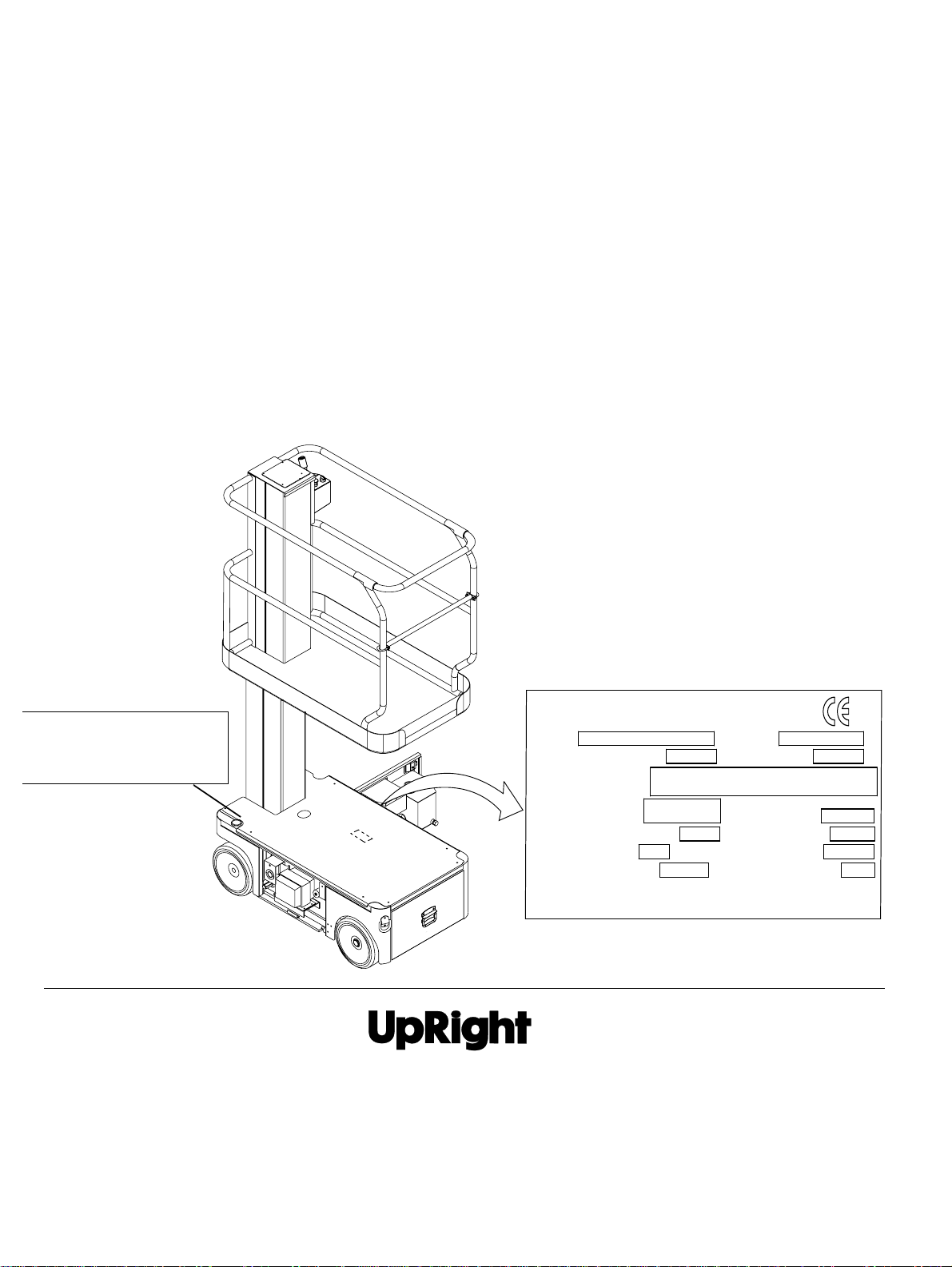
When contacting UpRight for service or parts information, be sure to include the MODEL and SERIAL NUM BERS from the
equipment nameplate. Should the nameplate be missing, the SERIAL NUMBER is also stamped on top of the chassis
above the front axle pivot.
FRANÇAIS
Lors des communications avec UpRight pour des informations au sujet de l’entretien ou des pièces, ne pas oublier d’inclure
les NUMÉROS DE MODÈLE et DE SÉRIE inscrits sur la plaque signalétique. Si la plaque sign alétique manque, le
NUMÉRO DE SÉRIE est également estampé sur le dessus du châssis, au-dessus de l’axe pivot avant.
DEUSTCH
Stellen Sie sicher, dass Sie die MODELL- und SERIENNUMMERN auf dem Gerätetypenschild angeben, wenn Sie sich mit
UpRight bezüglich Wartungs- oder Ersatzteilinformationen in Verbindung setzten. Sollte das Typenschild fehlen, finden Sie
die SERIENNUMMER auch auf dem Fahrwerk über der vorderen Schwenkachse.
Stamped Serial Number
Estampille de numéro de série
Eingestanzte Seriennummer
UpRight, Inc.
801 South Pine Street
Madera, California 93637
TEL: 559-662-3900
FAX: 559-673-6184
PARTS: 1-888-UR-PARTS
PARTS FAX: 1-800-669-9884
THIS PLATFORM IS NOT ELECTRICALLY INSULATED
Call Toll Free in U.S.A.
1-800-926-LIFT
PARKWEST IND EST,
UpRight
MODEL
MAX. PLATFORM HEIGHT
MAX. PLATFORM LOAD
MAX. LATERAL FORCE
MAX. CHASSIS INCLINATION
MAX. GRADEABILITY
MAX. FORWARD SPEED
TM12
227 Kg
400N Indoor
200N Outside
25%
CAUTION:ONLY TRAINED & AUTHORISED PERSONNEL MAY USE
THIS MACHINE-CONSULT OPERATORS MANUAL BEFORE USE.
CLONDALKIN,
DUBLIN, IRELAND.
SERIAL No.
3.73m
UNLADEN WEIGHT
2 Persons Indoor
=
1 Persons Outdoor
MAX. WIND SPEED
2°
BATTERY VOLTAGE
CHARGER INPUT VOLTAGE
1.0 m/s
NOMINAL POWER
+ Equipment
Unit S1, Park West Industrial Park
Friel Avenue
Nangor Road
Dublin 12, Ireland
TEL: +353 1 620 9300
FAX: +353 1 620 9301
780 Kg
12.5 m/s
24V
110/220V
3kW
505049-000
UpRight
Page 3
O
C
PERATION
M
ANUAL
WARNING
All personnel shall carefully read, understand and follow all safety rules and operating instructions
before operating or perform i ng main tenance on a ny UpRight aerial work plat form.
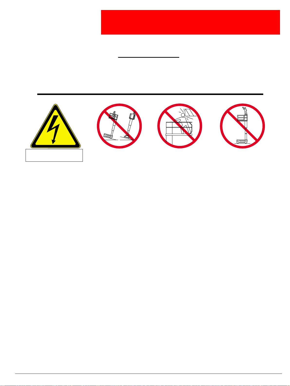
Safety Rules
Electrocution Hazard Tip Over Hazard
THIS MACHINE IS NOT
INSULATED!
USE OF THE AERIAL WORK PLATFORM: This aerial work platform is intended to lift persons and his tools as well as the material used
for the job. It is designed for repair and assembly jobs and assignments at overhead workplaces (ceilings, cranes, roof structures, buildings etc.). All other uses of the aerial work platform are prohibited!
THIS AERIAL WORK PLATFORM IS NOT INSULATED! For this reason it is imperative to keep a safe distance from live parts of electrical equipment!
Exceeding the specified permissible maximum load is prohibited! See “Platform Capacity” on page4 for details.
The use and operation of the aerial work platform as a lifting tool or a crane is prohibited!
NEVER exceed the manual force allowed for this machine. See “Manual Force” on page 4 for details.
DISTRIBUTE all platform loads evenly on the platform.
NEVER operate the machine without first surveying the work area for surface hazards such as holes, drop-offs, bumps, curbs, or debris;
and avoiding them.
OPERATE machine only on surfaces capable of supporting wheel loads.
NEVER operate the machine when wind speeds exceed this machine’s wind rating. See “Beaufort Scale” on page 4 for details.
IN CASE OF EMERGENCY push E M E RGENCY STOP switch to deactivate all powered fun ctions.
IF ALARM SOUNDS while pla tform is elevated, STOP, carefully lower platform. Move machine to a firm, level surface.
Climbing up the railing of the platform, standing on or stepping from the platform onto buildings, steel or prefab concrete structures, etc. ,
is prohibited!
Dismantling the entry gate or other railing components is prohibited! Always make certain that the entry gate is closed and securely
locked!
It is prohibited to keep the entry gate in an open po sit io n when the platform is raised!
To extend the height or the range by placing of ladders, scaffolds or similar devices on the platform is prohibited!
NEVER perform s ervice on machi ne while p latform is e levated without blocking elevating assembly.
INSPECT the machine thoroughly for cracked welds, loose or missing hardware, hydraulic leaks, loose wire connections, and damaged
cables or hoses before using.
VERIFY that all labels are in place and legible before using.
NEVER use a machine that is damaged, not functioning p roperly, or has damaged or missing labels.
To bypass any safety equipment i s prohi bited and prese nts a danger f or the perso ns on the aerial wor k plat form a n d in its w orking range.
NEVER charge batteries near sparks or open flame. Charging batteries emit explosive hydrogen gas.
Modifications to the aerial work platform are prohibited or permissible only at the approval by UpRight.
AFTER USE, secure the work platform from unauthorized use by turning the keyswitch off and removing key.
NEVER elevate the platform or drive
the m ac hine wh ile eleva ted unless
the machine is on a firm, level
surface.
ollision Hazard Fall Hazard
NEVER posit ion the pl at for m
without first checking for overhead
obstructions or other hazards.
NEVER climb, stand, or sit on
platform guard rails or midra il.
Operation Manual Page 1
Page 4

ONTENTS
C
Introduction . . . . . . . . . . . . . . . . . . . . . . . . . . . . . . . . . . . . . . . . . . . . . . . . . . . . . . . . . . . . . . . . . . . . . . . . . 3
General Description . . . . . . . . . . . . . . . . . . . . . . . . . . . . . . . . . . . . . . . . . . . . . . . . . . . . . . . . . . . . . . . . . . 3
Special Limitations . . . . . . . . . . . . . . . . . . . . . . . . . . . . . . . . . . . . . . . . . . . . . . . . . . . . . . . . . . . . . . . . . . . 4
Platform Capacity. . . . . . . . . . . . . . . . . . . . . . . . . . . . . . . . . . . . . . . . . . . . . . . . . . . . . . . . . . . . . . . . . . . . . . . . . . . . 4
Manual Force . . . . . . . . . . . . . . . . . . . . . . . . . . . . . . . . . . . . . . . . . . . . . . . . . . . . . . . . . . . . . . . . . . . . . . . . . . . . . . . 4
Beaufort Scale . . . . . . . . . . . . . . . . . . . . . . . . . . . . . . . . . . . . . . . . . . . . . . . . . . . . . . . . . . . . . . . . . . . . . . . . . . . . . . 4
Controls and Indicators . . . . . . . . . . . . . . . . . . . . . . . . . . . . . . . . . . . . . . . . . . . . . . . . . . . . . . . . . . . . . . . 5
Pre-Operati on Safety Inspection . . . . . . . . . . . . . . . . . . . . . . . . . . . . . . . . . . . . . . . . . . . . . . . . . . . . . . . . 5
System Function Inspection . . . . . . . . . . . . . . . . . . . . . . . . . . . . . . . . . . . . . . . . . . . . . . . . . . . . . . . . . . . 6
Operation . . . . . . . . . . . . . . . . . . . . . . . . . . . . . . . . . . . . . . . . . . . . . . . . . . . . . . . . . . . . . . . . . . . . . . . . . . . 7
Travel With Platform Lowered . . . . . . . . . . . . . . . . . . . . . . . . . . . . . . . . . . . . . . . . . . . . . . . . . . . . . . . . . . . . . . . . . . 7
Steering . . . . . . . . . . . . . . . . . . . . . . . . . . . . . . . . . . . . . . . . . . . . . . . . . . . . . . . . . . . . . . . . . . . . . . . . . . . . . . . . . . . 7
Elevating Platform . . . . . . . . . . . . . . . . . . . . . . . . . . . . . . . . . . . . . . . . . . . . . . . . . . . . . . . . . . . . . . . . . . . . . . . . . . . 7
Travel With Platform Elevated . . . . . . . . . . . . . . . . . . . . . . . . . . . . . . . . . . . . . . . . . . . . . . . . . . . . . . . . . . . . . . . . . . 7
Lowering Platform . . . . . . . . . . . . . . . . . . . . . . . . . . . . . . . . . . . . . . . . . . . . . . . . . . . . . . . . . . . . . . . . . . . . . . . . . . . 7
Emergency Lowering . . . . . . . . . . . . . . . . . . . . . . . . . . . . . . . . . . . . . . . . . . . . . . . . . . . . . . . . . . . . . . . . . . . . . . . . . 8
Parking Brake Release. . . . . . . . . . . . . . . . . . . . . . . . . . . . . . . . . . . . . . . . . . . . . . . . . . . . . . . . . . . . . . . . . . . . . . . . 8
After Use Each Day . . . . . . . . . . . . . . . . . . . . . . . . . . . . . . . . . . . . . . . . . . . . . . . . . . . . . . . . . . . . . . . . . . . . . . . . . . 8
Transporting the Machine . . . . . . . . . . . . . . . . . . . . . . . . . . . . . . . . . . . . . . . . . . . . . . . . . . . . . . . . . . . . . 9
By Crane . . . . . . . . . . . . . . . . . . . . . . . . . . . . . . . . . . . . . . . . . . . . . . . . . . . . . . . . . . . . . . . . . . . . . . . . . . . . . . . . . . 9
By Forklift . . . . . . . . . . . . . . . . . . . . . . . . . . . . . . . . . . . . . . . . . . . . . . . . . . . . . . . . . . . . . . . . . . . . . . . . . . . . . . . . . . 9
By Truck . . . . . . . . . . . . . . . . . . . . . . . . . . . . . . . . . . . . . . . . . . . . . . . . . . . . . . . . . . . . . . . . . . . . . . . . . . . . . . . . . . . 9
Maintenance. . . . . . . . . . . . . . . . . . . . . . . . . . . . . . . . . . . . . . . . . . . . . . . . . . . . . . . . . . . . . . . . . . . . . . . . 10
Blocking the Elevating Assembly . . . . . . . . . . . . . . . . . . . . . . . . . . . . . . . . . . . . . . . . . . . . . . . . . . . . . . . . . . . . . . . 10
Installation. . . . . . . . . . . . . . . . . . . . . . . . . . . . . . . . . . . . . . . . . . . . . . . . . . . . . . . . . . . . . . . . . . . . . . . . . . . . . 10
Removal . . . . . . . . . . . . . . . . . . . . . . . . . . . . . . . . . . . . . . . . . . . . . . . . . . . . . . . . . . . . . . . . . . . . . . . . . . . . . . 10
Hydraulic Fluid . . . . . . . . . . . . . . . . . . . . . . . . . . . . . . . . . . . . . . . . . . . . . . . . . . . . . . . . . . . . . . . . . . . . . . . . . . . . . 10
Check Hydraulic Fluid . . . . . . . . . . . . . . . . . . . . . . . . . . . . . . . . . . . . . . . . . . . . . . . . . . . . . . . . . . . . . . . . . . . . 10
Battery Maintenance . . . . . . . . . . . . . . . . . . . . . . . . . . . . . . . . . . . . . . . . . . . . . . . . . . . . . . . . . . . . . . . . . . . . . . . . 11
Battery Charging. . . . . . . . . . . . . . . . . . . . . . . . . . . . . . . . . . . . . . . . . . . . . . . . . . . . . . . . . . . . . . . . . . . . . . . . 11
Inspection and Maintenance Schedule . . . . . . . . . . . . . . . . . . . . . . . . . . . . . . . . . . . . . . . . . . . . . . . . . . 12
Daily Preventative Maintenance Checklist . . . . . . . . . . . . . . . . . . . . . . . . . . . . . . . . . . . . . . . . . . . . . . . 13
Labels . . . . . . . . . . . . . . . . . . . . . . . . . . . . . . . . . . . . . . . . . . . . . . . . . . . . . . . . . . . . . . . . . . . . . . . . . . . . . 14
Specifications . . . . . . . . . . . . . . . . . . . . . . . . . . . . . . . . . . . . . . . . . . . . . . . . . . . . . . . . . . . . . . . . . . . . . . 16
Page 2 Operation Manual
Page 5
NTRODUCTION
I
This manual covers all models of the TM12 Aerial Work Platform. This manual must be stored on the
machine at all times.
Read, understand and follow all safety rules and operating instructions before attempting to operate the
machine.
Introduction
ENERAL
G
ESCRIPTION
D
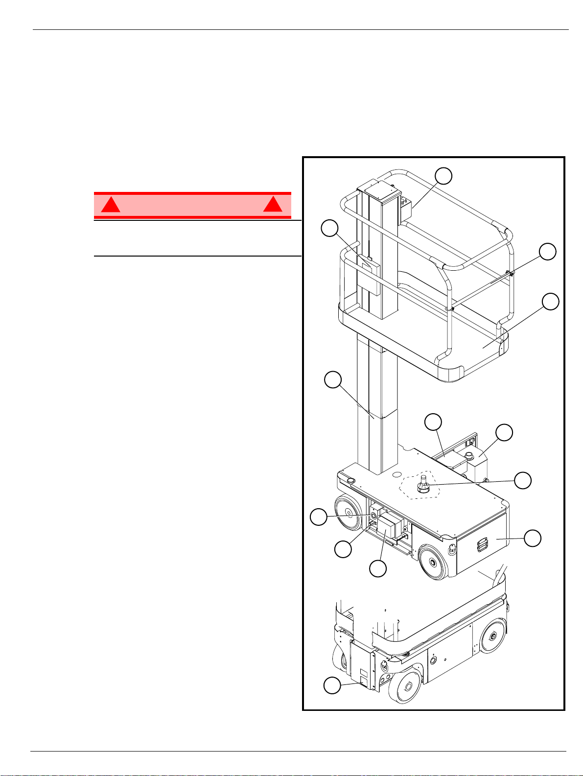
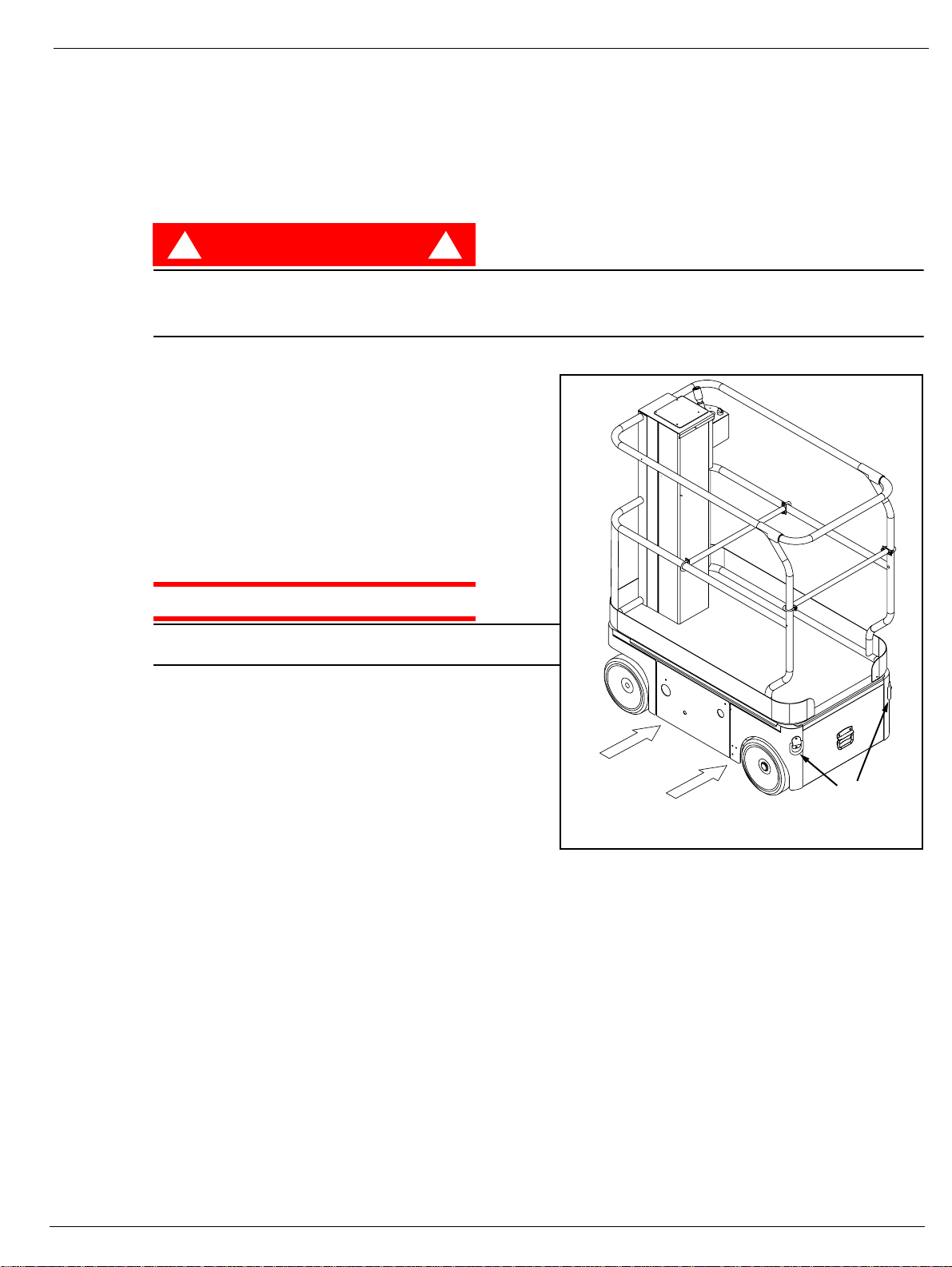
1. Platform
!
WARNING
DO NOT use the maintenance platform
without guardrails properly assem bled and
in place
2. Entry Bar
3. Elevating Mast
4. Platform Con trols
5. Manual Case
6. Electrical Box
7. Hydraulic Reser voir
8. Level Sensor
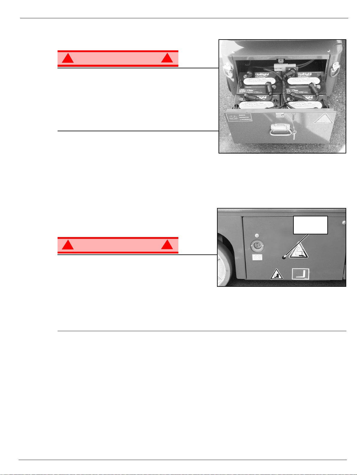
9. Battery Tray
10. Emergency Lowering Valve
11. Battery Charger
12. Drive Relief Valve
!
Figure 1: TM12 Series
4
5
2
1
3
6
7
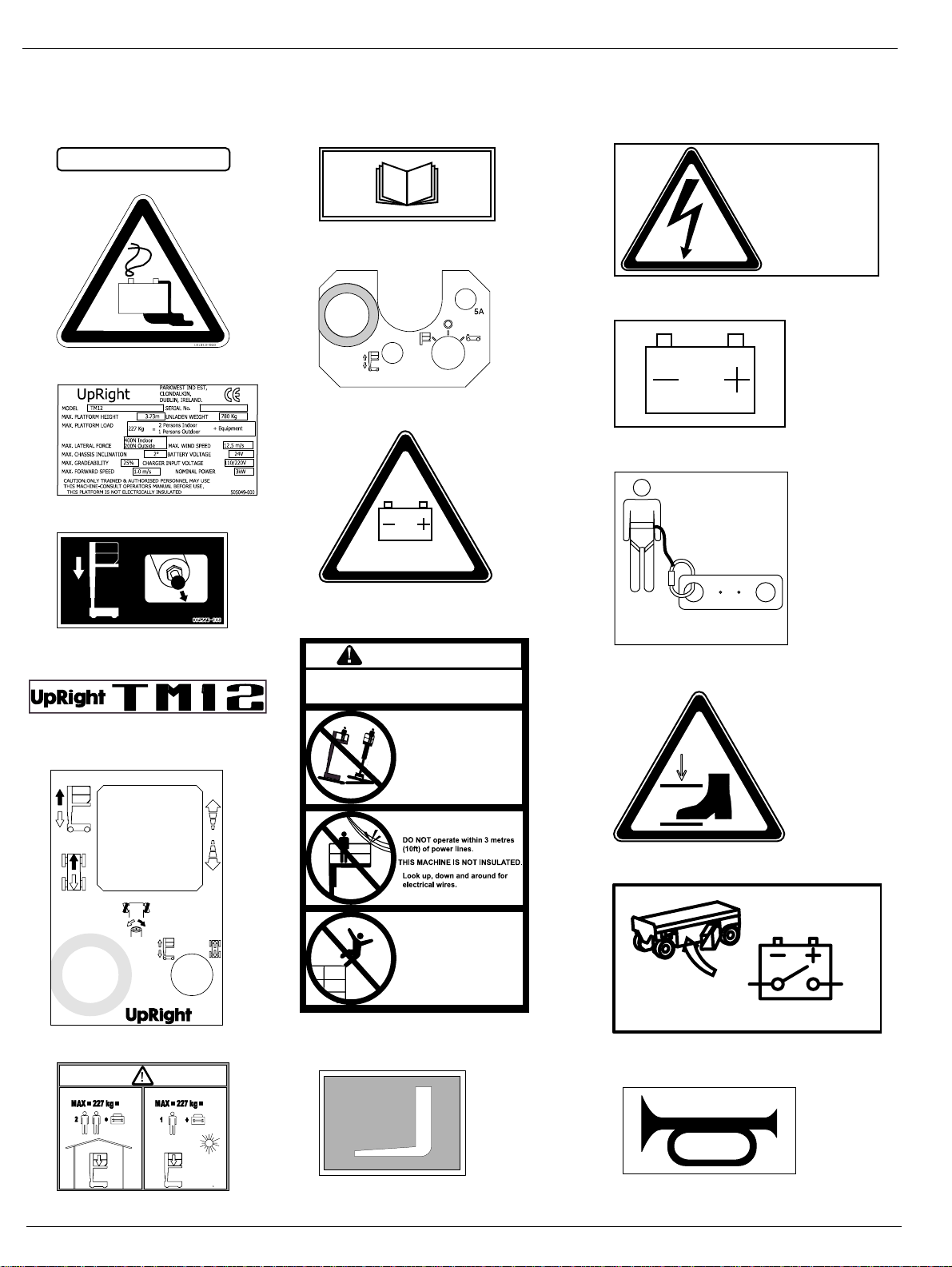
13. Charger Outlet Plug
8
13
9
12
11
10
Operation Manual Pag e 3
Page 6

Special Limitations
PECIAL
S
IMITATIONS
L
Travel with the platform raised is limited to creep speed range.
Elevating the platform is limited to firm, level surfaces only.
! !
DANGER
The elevating function shall ONLY be used when the work platform is level and on a firm surface.
The work platform is NOT intended to be driven over uneven, rough, or soft terrain.
P
LATFORM
The maximum platform capacity for the TM12 is 227 kg (500 lbs). Two people may occupy the platform
indoors, while only one may occupy the platform outdoors.
DANGER
! !
DO NOT exceed the maximum platform capacity or the platform occupancy limits for this machine.
M
ANUAL
Manual force is the force applied by the occupants to objects such as walls or other structures outside the
work pl atform.
F
C
APACITY
ORCE
The maximum allowable manual force is limited to 200 N (45 lbs.) of force per occupant, with a maximum
of 400 N (90 lbs .) for two occupants.
! !
DANGER
DO NOT exceed the maximum amount of manual force for this machine.
B
EAUFORT
Never operate the machine when wind speeds exceed 25 km/h (15 mph) [Beaufort scale 4].
BEAUFORT
RATING
3 3,4~5,4 12,25~19, 4 11.5~17.7 5 7.5~12.0 Papers and thi n branches move, flags wave.
4 5, 4~8,0 19,4~28,8 17.75~26.25 12.0~18 Dust is raised, p a per whirls up , and small branches swa y.
5 8,0~10,8 28,8~38,9 26.25~35.5 18~24.25 Shrubs w ith leaves start swaying. Wave crest s are a p parent i n pon ds or swa mps.
6 10,8~13,9 38,9~50,0 35.5~45.5 24.5~31 Tree branches move. Power lines whistle. It is difficult to open an umbrella.
7 13,9~17,2 50,0~61,9 45.5~56.5 31.~38.5 Whole trees sway. It is difficult to walk against the wind.
m/s km/h ft/s mph
S
WIND SPEED
CALE
GROUND CONDITIONS
Page 4 Operation Manual
Page 7
Controls and Indicators
ONTROLS AND
C
The operator shall know the location of each control and indicat or and have a thorough knowledge of the
functi on and operation of each before attempting to operate the unit.
NDICATORS
I
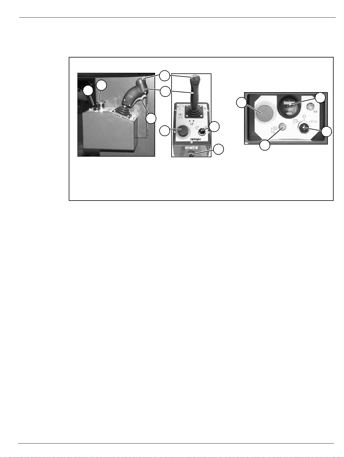
Platform Controller
2
5
Side View
1. Inter lock Swit ch
2. Platform Emergency Stop Switch
3. Control Lever
4. Steering Switch
5. Drive/Lift Switch
Figur e 2: Co nt rols and Indic ators
4
Chassis Controller (Right Side)
3
6
9
1
2
Top View
5
10
6. Chassis Emergency Stop Switch
7. Chassis Lift Switch
8. Chassis Key Switch
9. Hour Meter
10. Horn Button
7
8
P
RE
PERATION
-O
NOTE: Carefully read, understand and follow all safety rules, operating instructions, labels and National Safety
Instructions/Requirements. Perform the following steps each day before use.
1. Open the Chassis Door and inspect for damage, fluid leaks or missing parts.
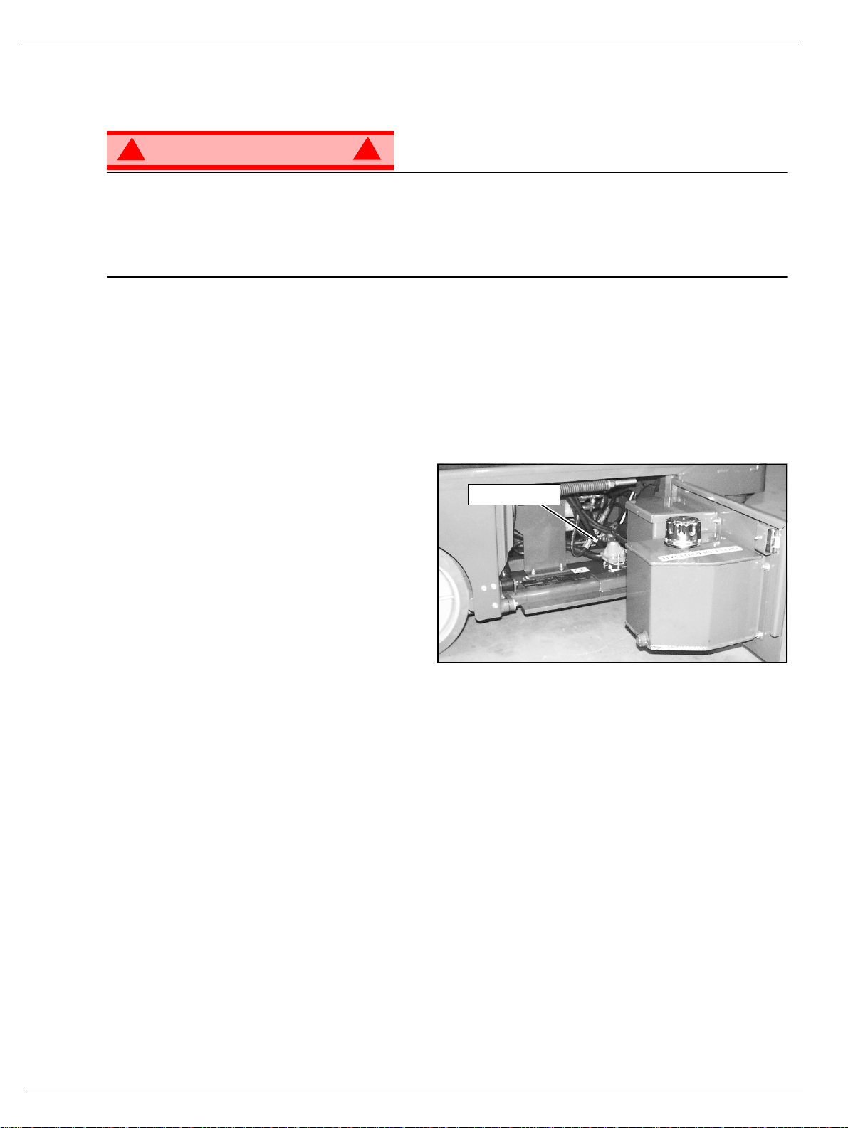
2. Check the level of the hydraulic fluid with the platform fully lowered. Open the Chassis Door and remove
the reservoir cap, fluid should be visible on the dipstick. Add recommended hydrauli c fluid if necessary.
See “Specifications” on page16.
3. Check that the fluid level in the batteries is correct. See “Battery Mainte nanc e” on page 11.
4. Verify that the batteries are charged.
5. Check that the A.C. extension cord has been disconnected from the chassis outlet.
6. Check that all guardrails are in place and all fasteners are properly tightened.
7. Inspect the machine thoroughly for cracked welds and structural damage, loose or missing hardware,
hydraulic leaks, damaged control cable and loose wire connections.
S
AFETY
NSPECTION
I
Operation Manual Pag e 5
Page 8
System Function Inspection
YSTEM
S
UNCTION
F
Refer to Figure 1 and Figur e2 fo r the locat ions of various controls and indicators.
!
WARNING
STAND CLEAR of the work platform while performing the following checks.
Before operating the machine, survey the work area for surface hazards such as holes, drop-offs, bumps
and debris.
Check in ALL directions, including above the work platform, for obstructions and electrical conductors.
Protect the control console cable from possible damage while performing checks.
1. Move the machine, if necessary, to an unobstructed area to allow for full elevation.
2. Turn the Chassis and Platform Emergency S top Switc hes ON by pulling the buttons out.
3. Turn and hold the Chassis Key Switch to CHASSIS.
4. Push the Chassis L ift Swi tch to the UP position and fully elevate the platform.
5. Visually inspect the mast assembly for damage or erratic operation. Check for missing or loose parts.
6. Verify that the depression mechanism supports have rotated into position under the machine.
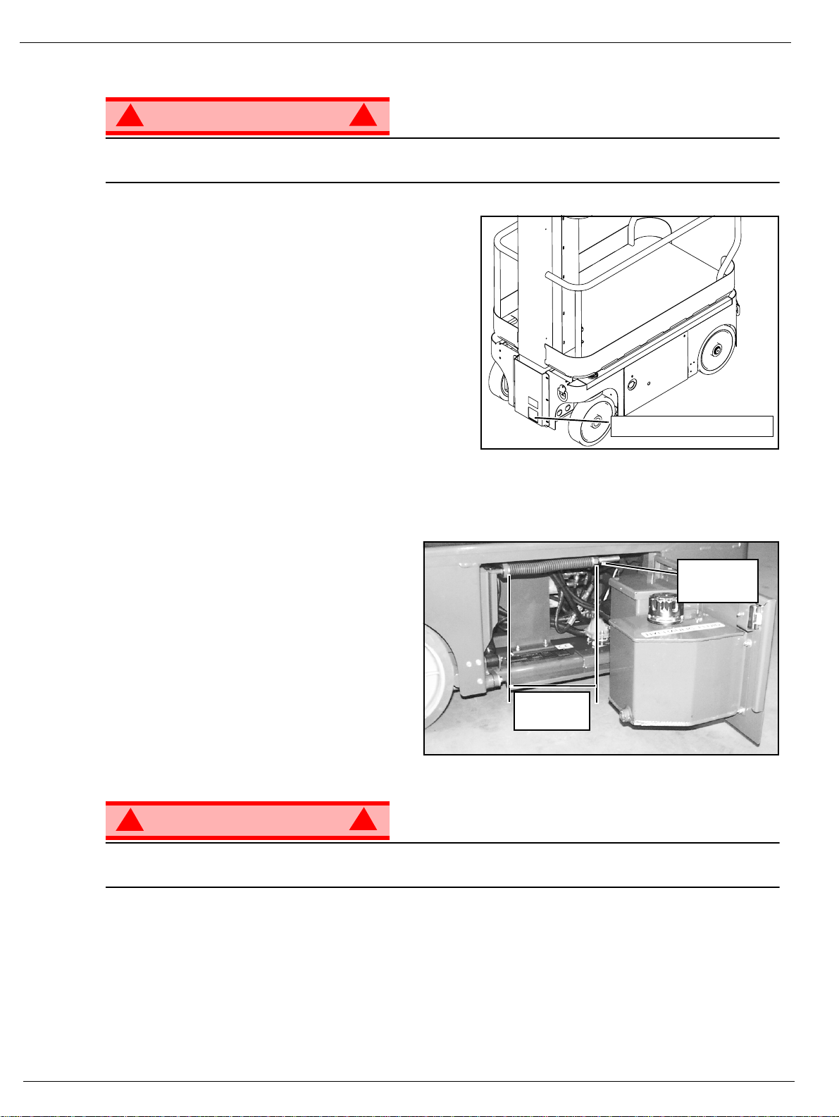
7. Check Level Sensor operation:
a. Open the door.
b. Push and hold the sensor off of level.
c. Push the Chassis Lift Switch to the UP
position.
• The alarm should sound, and the platform should not lift.
d. Close and latch the door.
8. Partially lower the platform by pushing the
Chassis Lift Switch to DOWN, and check the
operation of the audible lowering alarm.
9. Check the Chassis Emergency Lowering
Valve for proper operation (see Figure 4):
a. Open the valve by pulling the knob out.
b. Once the platform is fully lowered, close the valve by releasing the knob.
10. Push the Chassis Emergency Stop Switch down to the OFF position. All machine functions should be
disabled. Pull out the Chassis Emergency Stop Switch to resume.
11. Turn the Chassis Key Switch to DECK.
12. Check that the route is clear of persons, obstructions, holes and drop-offs, is level and capable of supporting the wheel loads.
13. After mounting platform, lower the bar across the entrance.
14. Position the Drive/Lift Switch to DRIVE.
15. Whi l e depressing the Interl ock Switc h, s lowly position the Control Lever to FORWARD then REVERSE
to check for speed and directional control. The farther you push or pull the Control Lever from center the
faster the machine w ill travel.
16. Push the Steering Switch RIGHT then LEFT to check for steering control.
17. Push the Platform Emergency Stop Switch do wn to the OFF position. All machine functions should be
disabled. Pull out the Platform Emergency Stop Switch to resume.
NSPECTION
I
!
Figur e 3: Lev el Sensor Location
Level Sensor
Page 6 Operation Manual
Page 9

PERATION
O
Operation
Before operating the machine, ensure that the Pre-Operation Safety Inspection has been completed and
that any de f ici encies ha ve been corrected. Never op erate a dam a g ed or ma l fu nc ti onin g machine. The
operator must be thoroug hly trained on this machine.
T
RAVEL
1. Check that the route is clear of people, obstructions, holes and drop-offs, is level and is capable of supporting wheel loads.
2. Verify that the Chassis Key Switch is turned to DECK and the Chassis Emergency Stop Switch is ON,
(pull button out).
3. After mounting the platform, lower the bar across entrance.
4. Check clearances above, below and to the sides of the machine.
5. Pull the Controller Emergency St op switch up to the ON po sition.
6. Position the Drive/Lift Switch to DRIVE.
7. While depressing the Interlock Switch, slowly push or pull the Control Lever to FORW ARD or REVERSE
position to travel in the desired direction. The farther you push or pull the Control Lever from center the
faster the machine w ill travel.
S
TEERING
NOTE: Steering is not self-centering. Wheels must be returned to straight ahead position by operating the Steering
Switch.
1. Position the Drive/Lift Switch to DRIVE.
2. While depressing the Interlock Switch, push the Steering Switch to RIGHT or LEFT to turn the wheels in
the desired direction. Observe the tires while maneuvering the machine to ensure proper direction.
W
ITH
P
LATFORM
L
OWERED
E
LEVATING
1. Position the Drive/Lift Switch to LIFT.
2. While depressing the Interlock Switch, push Control Lever forward to UP, the farther you push the Control Lever the faster the Platform will elevate.
3. If the machine is not level the Tilt Alarm will sound and the machine will not lift or drive. If the Tilt alarm
sounds the platform must be lowered and the machine moved to a level location before attempting to reelevate the Platform.
T
RAVEL
NOTE: The machine will travel at reduced speed when the platform is elevated.
1. Check that the route is clear of persons, obstructions, holes and drop-offs, is level and capable of supporting the wheel loads.
2. Check clearances above, below and to the sides of the platform.
3. Position the Drive/Lift Switch to the DRIVE position.
4. While depressing the Interlock Switch, push Control Lever to FORWARD or REVERSE f o r desired di r ection of travel.
5. If the machine is not level the Tilt Alarm will sound and the machine will not lift or drive. If the Tilt alarm
sounds the platform must be lowered and the machine moved to a level location before attempting to reelevate the Platform.
W
P
LATFORM
P
ITH
LATFORM
E
LEVATED
L
OWERING
1. Position the Drive/Lift Switch to LIFT.
2. While depressing the Interlock Switch, pull back on the Control Lever.
Operation Manual Pag e 7
P
LATFORM
Page 10
Operation
E
MERGENCY
!
WARNING
If the platform should fail to lower, NEVER climb down the elevating assembly.
Stand clear of the elevating assembly while operating the Emergency Lowering Valve Knob.
Ask a person on the ground to open the Emergency
Lowering Valve to lower the platform. The Emergency
Lowering Valve is located at the front of the chassis.
1. Open the Emergency Lowering Valve by pulling the
knob out.
2. To close, release the knob.
NOTE: The platfo rm will no t eleva t e if the Emergency Lowering
Valve is open.
L
OWERING
!
Figur e 4: Emergency Lowering Valve
Emergency Lowering Valve
P
ARKING
Perform the following procedure o n l y when the machine will not operate under its own power and it is necessary to move the machine, or when winching onto a trailer to transport.
1. Remove the spring compression nut so the
spring is loose and the brake bars are away
from th e tires.
2. The machine will now roll when pushed or
pulled.
After moving the machine and before normal
operation:
1. Replace the spring compression nut and
tighten until the spring measures 22,2-22,9
cm (8¾”-9”) in length, verify that the brake
bars have fully engaged the tires before the
machine is operated.
!
WARNING
Never tow faster than 0,3 m/sec. (1 ft./sec.).
Never operate the machine with the parking brakes released. Serious injury or damage could result.
B
RAKE
R
ELEASE
Figur e 5: Parking Brake Release
Spring
Compression
Nut
22,2 cm to
22,9 cm
”
!
A
FTER
1. Ensure that the platform is fully lowered.
2. Park the machine on a fir m level surface, preferably under cover, secure against vandals, children and
3. Turn the Chassis Key Switch to OFF and remove the key to prevent unauthorized operation.
Page 8 Operation Manual
U
unauthorized operation.
SE
E
ACH
D
AY
Page 11
Transporting the Machine
RANSPORTING THE
T
BY C
BY F
Forklifting is for transport only .
See spe cifications for weight of machi ne and be cert ain that forklift is of adequate capacity to lift the
machine.
BY T
1. Maneuver the machine into transpor t position and
2. Secure the machine to the transport vehicle with
RANE
Secure the straps to chassis lifting/tie d own points only.
ORKLIFT
! !
DANGER
Forklift from the side by lifting under the Chassis.
RUCK
chock wheels.
chains or straps of adequate load capac ity
attached to the chassis lifting/t i e down points.
M
ACHINE
Figure 6: Transporting the Machine
CAUTION
Overtightening of the chains or straps attached to the
Tie Down lugs may result in damage to the machine
Forklift From
Side
Typical Tie Down/Lift Points
(D-Rings)
Operation Manual Pag e 9
Page 12
Maintenance
AINTENANCE
M
!
WARNING
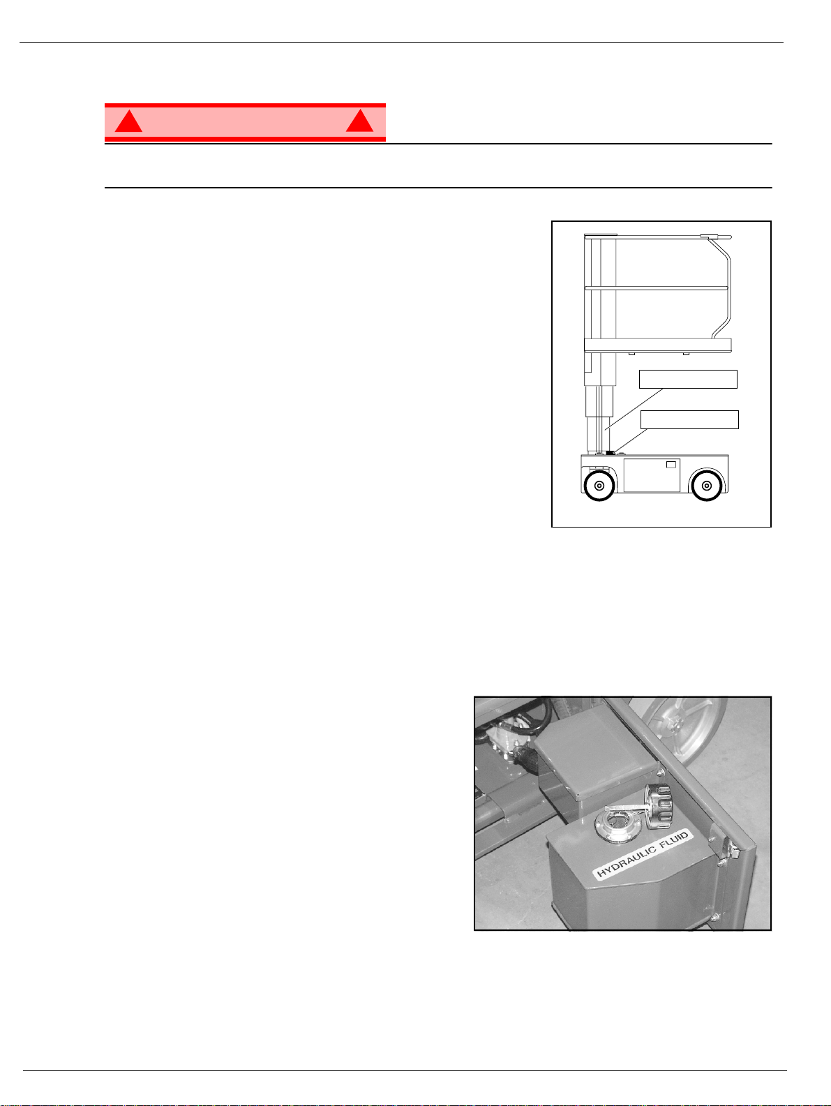
Never perform service while the platform is elevated without first blocking the elevating assembly.
DO NOT stand in the elevating asse mbly area whi le deploying or storing the brace.
B
LOCKING THE
I
NSTALLATION
1. Park the machine on firm level ground.
2. Verify that both Emerge ncy Stop Switc hes are ON.
3. Turn and hold the Chassis Key Switch to CHASSIS.
4. Position the Chassis Lift Switch to UP and elevate the platform
approximately 1,2 m (4 ft.).
5. Place a solid wood block, 51mm x 100mm x 45cm (2”x 4”x18”)
between the second mast section and Chassis just behind the
mast a ssem b ly.
6. Push the Chassis Lift Swi tch to t he DOWN pos ition and gradually
lower the platform until the second mast section is supported by
the block.
R
EMOVAL
1. Push the Chassis Lift Switch to the UP position and gradually raise platform until the wood block can be
removed.
2. Remove the block.
3. Push the Chassis Lift Switch to the DOWN position and completely lower the platfor m.
E
LEVATING
!
Figur e 7: Supporting the Elevating Assembly
A
SSEMBLY
Number 2 Mast
Wood Block
H
YDRAULIC
The hydraulic fluid reservoir is located in the chassis door.
NOTE: Never add fluid if the platform is elevated.
C
HECK HYDRAULIC FLUID
1. Make sure that the platform is fully lowered.
2. Open the chassis door.
3. Remove the filler cap from the hydraulic fluid reservoir.
4. Check the fluid level on the dip stick on the filler cap.
5. Add the appropriate fluid to bring the level to the
FULL mark. See “S pec if ications” on pag e16
F
LUID
Figure 8: Hydraulic Fluid Reservoir and Dipstick
Page 10 Operation Manual
Page 13
Maintenance
B
ATTERY
!
WARNING
M
AINTENAN CE
!
Hazard of explosive gas m ixture. Keep sparks, flame,
and smoking material away from batteries.
Always wear safety glasses when working near batteries.
Battery fluid i s highly corrosive. Thoroughly rins e away
any spilled fluid with clean water.
Always replace batteries with UpRight batteries or
manufacturer approved replacements weighing 26,3 kg
(58 lbs.) each.
• Check the battery fluid level daily, especially if the
machine is being used in a warm, dry climate.
• If electrolyte level is lower than 10 mm (
the plates add distilled water only. DO NOT use tap water with high mineral content, as it will shorten
battery life.
• Keep the terminals and tops of the batteries clean.
• Refer to the Serv ice Manual to extend battery life and for complete service instructions.
B
ATTERY CHARGING
Charge the batteries at the end of each work shift or
sooner if the batteries have been discharged.
3
/
in.) above
8
Figure 10: Battery Charge Indi cato r
Figure 9: Access to Batter ies
Battery
Charge
Indicator
!
WARNING
Charge the batteries in a well ventilated area.
!
Do not charge the batteries when the machine is near a
source of sparks or flames.
Permanent damage to the batteries will result if the
batteries are not immediately recharged after
discharging.
Never leave the battery charger operating for more than two days.
Never disconnect the cables from the batteries when the charger is operating.
Keep the charger dry.
1. Check the ba tt ery fluid level. If th e ba ttery fl uid level is lowe r than 10 mm (
distilled water only .
2. Connect an appropriate extension cord to charger outlet plug in Left Module Door. Plug the extension
cord into a properly grounded outlet of proper voltage and frequency.
3. The charger turns on automatically after a short delay. The LED charge indicator will illuminate. After
completion of the charge cycle the LED will blink, indicating that the charger is in a cont inuing maintenance mode. DO NOT leave the charger plugged in for more than 48 hours, as permanent damage to
the batteries may occur.
3
/
in.) above the plates add
8
NOTE: The battery charger circuit must be used with a GFI (Ground Fault Interrupt) outlet.
NOTE: DO NOT operate the machine while the charger is plugged in.
Operation Manual Page 11
Page 14

Inspection and Maintenance Schedule
NSPECT ION AND
I
The Comple te Inspection consist s of periodic visual and operational checks, along with periodic minor
adjustments that assure proper performance. Daily inspection will prevent abnormal wear and prolong the
life of all systems. The inspection and maintenance schedule should be performed at the specified intervals. Inspection and maintenance shall be performed by personnel who are trained and familiar with
mechanical and electrical procedures.
!
WARNING
Before performing preventative maintenance, familiarize yourself with the operation of the machine.
Always block the elevating assembly wheneve r i t is necessa ry to perform maintenance while the
platform is elevated.
The daily preventative maintenance checklist has been designed for machine service and maintenance.
Please photocopy the Daily Preventative Maintenance Checklist and use the checklist when inspecting
the machine.
AINTENANCE
M
CHEDULE
S
!
Page 12 Operation Manual
Page 15

Daily Preventative Mai ntenance Checklist
AILY
D
M
AINTENANCE
REVENT ATIVE
P
T
ABLE KEY
M
Y = Yes/Acceptable
N = No/Not Acceptable
R = Repaired/Acceptable
COMPONENT INSPECTION OR SERVICES Y N R
Battery
Chassis
Control Cable
Contr olle r Check switch operation.
Drive Motors Check for operation and leaks.
Elevating Assembly Inspect for structural cracks.
Emergency H ydraulic
System
Check electrolyte level .
Check battery ca ble con d iti on.
Check hoses for pinch or rubbing points.
Check welds for cr acks.
Check the exterior of th e cable for pinching,
binding or wear .
Operate the emerge ncy l ow ering valve and
check for se rviceability.
AINTENANCE
P
REVENTATIVE
Date: _______________________________________
Owner:______________________________________
Model No: ___________________________________
Serial No:____________________________________
Serviced By: _________________________________
COMPONENT INSPECTION OR SERVICES Y N R
Entire Unit Check for and repair co llisio n d ama ge.
Hydraulic Fluid Check fluid level.
Hydraulic Pum p Check for hose fitting leaks.
Hydraulic System Check for leaks.
Labels
Platform Deck and
Rails
Platform Deck and
Rails
Tires Ch eck f or damage.
HECKLIST
C
M
AINTENANCE
Check for peeling, missing, or unreadable
labels & replace.
Check welds for cracks.
Check condition of deck.
R
EPORT
Operation Manual Page 13
Page 16
Labels
ABELS
L
These labels shall be present and in good condition before operating the machine. Be sure to read, understand and follow these labels when operating the machine.
HYDRAULIC FLUID
1 060197-001
2 101210-000
3 505049-000
060197-000
010076-901
11 010076-901
THIS PLATFORM IS
NOT INSULATED
DIESE ARBEITSBÜHNE
IST NICHT ISOLIERT
CETTE PLATEFORME
N'EST ISOLEE
100102-900
20 100102-900
12 505079-000
066522-900
21 066522-900
26,3 kg +
15 062562-951
5 005223-909
6 505077-000
7 505078-000
FAILURE TO READ, UNDERSTAND AND OBEY THE
DANGER
FOLLOWING SAFETY RULES WILL CAUSE DEATH
OR SERIOUS INJURY.
TIP-OVER HAZARDS
DO NOT elevate or drive
elevated on slopes or soft ground
DO NOT drive into holes or over
drop offs.
Do not exceed 113Kg (1 person)
on the slide out platform.
ELECTROCUTION HAZARD
22 068635-001
23 501453-000
FALL HAZARD
DO NOT climb on guardrail
Make sure guardrails are fastened
securely.
Secure gate across enterance.
DO NOT use ladders or scaffolding
on the platform.
DO NOT climb down linkage.
16 505076-000
503723-000
24 503723-000
!
014222-903
107052-000
9 107052-000
19 014222-903
25 107053-000
Page 14 Operation Manual
Page 17

Labels
Figure 11: Safety Labels Locations
Operation Manual Page 15
Page 18

Specifications
PECIFICATIONS
S
ITEM TM12
Working Height 5,83 m (19 ft.)
Maximum Platform Height 3,83 m (12.5 ft. )
Minimum Platform Height 48,3 cm (19 in.)
Weight 776 kg (1710 lbs.)
Overall Width 76 cm (30 in.)
Overall Height 165 cm (65 in.)
Overall Length 1,36 m (53.5 in.)
Platform Lowered 3,65 km/h (2.27 mph)
Plat f orm Raise d 0,87 km/h (0.54 mph )
Maximum Hydraulic System Pressure 165 bar (2400 p s i)
Normal above 32° F [0° C]
Low Temp. below 32° F [0° C]
below 0° F [-17° C]
Platform Size 73,7 cm x 1,04 m (29 in. x 41 in.)
Maximum Platform Capacity 227 kg (5 00 lbs.)
Maximum N umber of Occupants 2 People indoors/1 person ou tdo or s
Height
Dimensions
Drive Speed
Energy Source 24V battery pack
Four 220 ampere hour, 6 Volt batteries, min. wt. 26,3 kg (58 lbs.) each
4 HP DC electric m otor
System Vo ltage 24 VDC
Battery Charger 20 AMP, 220 V AC 50Hz
Battery Duty Cycle 25% for 8 Ho ur s
Hydraulic Reservoir Capac ity 7,2 L (1.9 gal)
Hydraulic Fluid
ISO #46
ISO #32
ISO #15
Lift System One Single Stag e Lift Cylinder
Drive Control Proportional
Control System
Horizontal Drive Dual Front W heel
Tires 30,5 cm (12 in.) diameter solid rubber, Non-marking
Parking Brakes Dual, Spring Applied, Hydraulic R e lease
T ur nin g R a dius 37 cm (14.5 in.) Inside
Maximum Gradeability 14 º (25%)
Wheel Base 97,8 cm (38.5 in.)
Guardrails 1,10 m (43 in.)
T oeboard 152 mm (6 in.)
Noise Level
Proportiona l Contro l Handle with In terlock, Select or Sw itc h,
Red Mu shr oom Emerge ncy St op Sw it ches
*Specifica tions are subje ct to change w ithout notic e . Hot weather or heavy use may affect performa n ce.
Refer to the Service Manual for complete parts and service information.
This machine meets or exceeds all applicable CE and GS machinery directive requirements.
Page 16 Operation Manual
Page 19

G
Ri
d’élect
Ri
d’élect
Ri
d’élect
Ri
d’élect
UIDE DE L’OPÉRATEUR
AVERTISSEMENT
Tout le personnel doit lire attentivement et respecter toutes les consignes de sécurité avant
Consignes de sécurité
Consignes de sécurité
Consignes de sécuritéConsignes de sécurité
d’entretenir ou d’ut iliser une plate-forme élévatrice UpRight.
sque
sque
sque
sque
CETTE MACHINE
N’EST PAS ISOLÉE !
USAGE DE LA PLATE-FORME ÉLÉVATRICE : Cette plate-forme élév atri ce est de stinée au lev a ge de tout e pe rsonne , d e son out ill age et
des matériaux utilisés sur le chantier. Elle est conçue pour les travaux de réparations et d’assemblage sur les points élevés (plafonds,
grues, charpentes de toit, immeubles, etc.). T out autre usage de la plate-forme élévatric e e s t interdit !
CETTE PLATE-FORME ÉLÉVATRICE N’EST PAS ISOLÉE ! C’est pourquoi i l est impératif de rester à distance sûre des lignes et
équipements électriques sous tension !
Il est in te rd it de dépasser la charge maximum admissible. Voir « Capacité de la plate-forme» à la page 20 pour plus de détails.
Il est in te rd it d’utiliser la plate-forme comme appareil de levage ou grue !
NE JAMAIS dépasser la force manuelle autorisée pour cette machine. Voir « Force manuelle » à la page 20 pour plus de détails.
RÉPARTIR uniformément toutes les charges placées sur la plate-forme.
NE JAMAIS utiliser la machine sans avoir d’abord vérifié si la zone de trava il est exempte de dangers tel s que des trous, d énivellations,
bosses, trottoirs ou débris; et les éviter.
N’UTILISER la machine que sur des surfaces pouvant suppor t e r l a charge des roues.
NE JAMAIS utiliser la machine lorsque la vitesse du vent dépasse les spécifications pour la machine. Voir « Échelle de Beaufort » à la
page 20 pour plus de détails.
EN CAS D’URGENCE, appuyer sur le bouton d’ARRÊT D’URGENCE pour désacti ver toutes les fon c tions.
SI L’ALARME RETENTIT lorsque la plate-forme est élevée, ARRÊTER, abaiss er la plate-for me avec précaution. Conduire la machine
jusqu’à une surface plane et ferme.
Il est in te rd it de monter ou de se tenir sur les garde-corps de la plate-forme et de passer de la plate-forme à un immeuble, une st ructure
préfabriquée, etc. !
Il est in te rd it de retirer le portillon ou toute autre pièce de garde-corps ! Toujours vérifier que le portillon est fermé et verrouillé !
Il est in te rd it de maintenir le portillon en pos itio n ou verte lorsque la plate- forme est élevée !
Il est in te rd it d’accroître la hauteur ou la portée de la plate-forme au moyen d’échelles, échafaudages ou autres dispositifs similaires !
NE JAMAIS effectuer de travaux d’entretien sur la machine , si la plate-forme est en positio n élevée, sans tout d’abord bloquer le système
d’élévation.
INSPECTER minutieusement la machine en vue de soudures fissurées, de pièces de boulonnerie manquantes ou desserrée s, de fu ites
hydrauliques, de branchements électriques desserrés ou de câbles et flexibles endommagés avant d’utiliser la machine.
VÉRIFIER que tous les autocollants sont en place et lisibles avant d’utiliser la machine.
NE JAMAIS utiliser une machine qui est endommagée, qui ne fonctionne pas correctement ou dont les autocollants sont manquants ou
endommagés.
Il est in terdit de mettre tout dispositif de sécurité hors service, ce qui mettrait en danger les personnes à bord de la plate-forme et celles
se trouvant dans la zone de travail.
NE JAMAIS charger les batteries à proximité d’étince lles ou d’une flamme vive . Lors de la charge, les bat teries dégagent de l’hydrogène,
un gaz explosif.
Sauf autorisation de la part d’UpRight, toute modification de la plate-forme est interd it e.
APRÈS AVOIR UTILISÉ la plate-forme élévatrice, mettre le contacteur à clé en position d’arrêt (OFF), puis retir er la clé afin d’empêcher
l’utilisation non autorisée de la plate-forme.
rocution
rocution
rocution
rocution
Risque de ba sculem ent
Risque de ba sculement Risque de collision
Risque de ba sculem entRisque de ba sculem ent
NE JAMAIS élever la plate-forme
ou conduire la machine avec
la plate-forme élevée si la machine
ne se trouve pas sur une surface
plane et ferme.
Risque de collision Risque de chute
Risque de collisionRisque de collision
NE JAMAIS positionner la plate-forme
avant de s’être assuré de l’absence
d’obstacles en hauteur
ou aut res dange rs.
Risque de ch ute
Risque de ch uteRisque de ch ute
NE JAMAIS monter, ni se tenir
debout ou assi s sur les ram pes
du garde-corps.
Guide de l’ opérateur Page 17
Page 20

ABLE DES MATIÈRES
T
Introduction . . . . . . . . . . . . . . . . . . . . . . . . . . . . . . . . . . . . . . . . . . . . . . . . . . . . . . . . . . . . . . . . . . . . . . . . 19
Description générale. . . . . . . . . . . . . . . . . . . . . . . . . . . . . . . . . . . . . . . . . . . . . . . . . . . . . . . . . . . . . . . . . 19
Limitations parti c ulières. . . . . . . . . . . . . . . . . . . . . . . . . . . . . . . . . . . . . . . . . . . . . . . . . . . . . . . . . . . . . . 20
Capacité de la plate-forme. . . . . . . . . . . . . . . . . . . . . . . . . . . . . . . . . . . . . . . . . . . . . . . . . . . . . . . . . . . . . . . . . . . . 20
Force manuelle. . . . . . . . . . . . . . . . . . . . . . . . . . . . . . . . . . . . . . . . . . . . . . . . . . . . . . . . . . . . . . . . . . . . . . . . . . . . . 20
Échelle de Beaufort . . . . . . . . . . . . . . . . . . . . . . . . . . . . . . . . . . . . . . . . . . . . . . . . . . . . . . . . . . . . . . . . . . . . . . . . . 20
Commandes et indicateurs . . . . . . . . . . . . . . . . . . . . . . . . . . . . . . . . . . . . . . . . . . . . . . . . . . . . . . . . . . . 21
Inspection de sécurité avant utilisation . . . . . . . . . . . . . . . . . . . . . . . . . . . . . . . . . . . . . . . . . . . . . . . . . 21
Essai de fonction nement des systèmes . . . . . . . . . . . . . . . . . . . . . . . . . . . . . . . . . . . . . . . . . . . . . . . . . 22
Utilisation . . . . . . . . . . . . . . . . . . . . . . . . . . . . . . . . . . . . . . . . . . . . . . . . . . . . . . . . . . . . . . . . . . . . . . . . . . 23
Déplacement av ec la plat e-f orme abaissée. . . . . . . . . . . . . . . . . . . . . . . . . . . . . . . . . . . . . . . . . . . . . . . . . . . . . . . 23
Direction . . . . . . . . . . . . . . . . . . . . . . . . . . . . . . . . . . . . . . . . . . . . . . . . . . . . . . . . . . . . . . . . . . . . . . . . . . . . . . . . . . 23
Élévation de la plate-forme. . . . . . . . . . . . . . . . . . . . . . . . . . . . . . . . . . . . . . . . . . . . . . . . . . . . . . . . . . . . . . . . . . . . 23
Déplacement av ec la plate-forme élevée. . . . . . . . . . . . . . . . . . . . . . . . . . . . . . . . . . . . . . . . . . . . . . . . . . . . . . . . . 23
ABAISSEMENT DE LA PLATE-FORME . . . . . . . . . . . . . . . . . . . . . . . . . . . . . . . . . . . . . . . . . . . . . . . . . . . . . . . . . 23
Abaissement d’urgence . . . . . . . . . . . . . . . . . . . . . . . . . . . . . . . . . . . . . . . . . . . . . . . . . . . . . . . . . . . . . . . . . . . . . . 24
Desserrage de frein de stationnement . . . . . . . . . . . . . . . . . . . . . . . . . . . . . . . . . . . . . . . . . . . . . . . . . . . . . . . . . . . 24
Après utilisation, tous les jours. . . . . . . . . . . . . . . . . . . . . . . . . . . . . . . . . . . . . . . . . . . . . . . . . . . . . . . . . . . . . . . . . 24
Transport de la machine . . . . . . . . . . . . . . . . . . . . . . . . . . . . . . . . . . . . . . . . . . . . . . . . . . . . . . . . . . . . . . 25
Par grue . . . . . . . . . . . . . . . . . . . . . . . . . . . . . . . . . . . . . . . . . . . . . . . . . . . . . . . . . . . . . . . . . . . . . . . . . . . . . . . . . . 25
Par chariot élévateur à fourche . . . . . . . . . . . . . . . . . . . . . . . . . . . . . . . . . . . . . . . . . . . . . . . . . . . . . . . . . . . . . . . . 25
Par camion . . . . . . . . . . . . . . . . . . . . . . . . . . . . . . . . . . . . . . . . . . . . . . . . . . . . . . . . . . . . . . . . . . . . . . . . . . . . . . . . 25
Entretien. . . . . . . . . . . . . . . . . . . . . . . . . . . . . . . . . . . . . . . . . . . . . . . . . . . . . . . . . . . . . . . . . . . . . . . . . . . 26
Blocage du système d’élévation. . . . . . . . . . . . . . . . . . . . . . . . . . . . . . . . . . . . . . . . . . . . . . . . . . . . . . . . . . . . . . . . 26
Installation. . . . . . . . . . . . . . . . . . . . . . . . . . . . . . . . . . . . . . . . . . . . . . . . . . . . . . . . . . . . . . . . . . . . . . . . . . . . . 26
Retrait . . . . . . . . . . . . . . . . . . . . . . . . . . . . . . . . . . . . . . . . . . . . . . . . . . . . . . . . . . . . . . . . . . . . . . . . . . . . . . . . 26
Fluide hydraulique . . . . . . . . . . . . . . . . . . . . . . . . . . . . . . . . . . . . . . . . . . . . . . . . . . . . . . . . . . . . . . . . . . . . . . . . . . 26
Vérifier le niveau de fluide hydraulique. . . . . . . . . . . . . . . . . . . . . . . . . . . . . . . . . . . . . . . . . . . . . . . . . . . . . . . 26
Entretien des batteries. . . . . . . . . . . . . . . . . . . . . . . . . . . . . . . . . . . . . . . . . . . . . . . . . . . . . . . . . . . . . . . . . . . . . . . 27
Chargement des batteries. . . . . . . . . . . . . . . . . . . . . . . . . . . . . . . . . . . . . . . . . . . . . . . . . . . . . . . . . . . . . . . . . 27
Programmes d’inspection et d’entretien. . . . . . . . . . . . . . . . . . . . . . . . . . . . . . . . . . . . . . . . . . . . . . . . . 28
Liste de co ntrôle d’entretien préventif quotidien. . . . . . . . . . . . . . . . . . . . . . . . . . . . . . . . . . . . . . . . . . 29
Autocollants. . . . . . . . . . . . . . . . . . . . . . . . . . . . . . . . . . . . . . . . . . . . . . . . . . . . . . . . . . . . . . . . . . . . . . . . 30
Caractéristiques . . . . . . . . . . . . . . . . . . . . . . . . . . . . . . . . . . . . . . . . . . . . . . . . . . . . . . . . . . . . . . . . . . . . 32
Page 18 Guide de l’opérateur
Page 21

NTRODUCTION
I
Ce manuel s’applique à tous l es m odèles TM 12 de plate-f orme élévatric e. Veiller à garder ce manuel sur
la machine en tout temps.
Lire, veiller à bien comprendre et respecter toutes les règles de sécurité et instructions d’utilisation avant
d’essayer d’utiliser la machine.
ESCRIPTION GÉNÉRALE
D
1. Plate-forme
AVERTISSEMENT
! !
NE PAS utiliser la plate-forme sans que les
garde-corps soient correcte ment assemb lés
et installés.
2. Barre d’entrée
Introduction
Figure 1 : Série TM 12
4
5
2
3. Mât élévateur
4. Commandes de la plate-forme
5. Coffret du manuel
6. Boîtier électrique
7. Réservoir hydraulique
8. Capteur de niveau
9. Bac de batterie
10. Vanne d’abaissem ent d’urgence
11. Chargeur de batterie
12. Vanne de désengagement
de conduite
13. Prise du chargeur
1
3
6
7
8
13
9
12
11
10
Guide de l’opérateur Page 19
Page 22

Limitations particulières
IMITATIONS PARTICULIÈRES
L
Le déplacement avec la plate-forme élevée est limité à la gamm e de vites ses rampantes.
La plate-forme ne doit être élevée que si elle se trouve sur une surface plane et ferme.
! !
DANGER
La fonction d’élévation doit être ut ilisée SEULEMENT lorsque la plate-forme est de niveau et placée sur
une surface plane et ferme.
La plate-forme élévatrice n’est PAS conçue pour être conduite sur terrain inégal, accidenté ou meuble.
C
APACITÉ DE LA PLATE-FORME
La capacité maximum de la plate-forme du modèle TM 12 est 227 kg (500 lb). À l’intérieur, deux
personnes peuvent occuper la plate-forme; à l’extérieur, une seule personne est autorisée.
DANGER
! !
NE PAS dép asse r la capacité de charge ou le nombre d’occupants maximum de cette machine.
F
ORCE MANUELLE
La force manuelle est la force appliquée par les occupants sur des objets tels que murs ou autres
structures extérieures à la machine.
La force manuelle maximale admissible est de 200 N (45 lb) par occupant, avec un maxi mum de 4 00 N
(90 lb) pour deux occupants.
! !
DANGER
NE PAS dép a sser la force manuelle maximale admissible pour cette machine.
É
CHELLE DE
Ne jamais utiliser la machine par vents soufflant à plus de 25 km/h (15 mi/h) (force 4 de l’échelle de
Beaufort).
FORCE
BEAUFORT
3 3,4~5,4 12,25~19, 4 11,5~17,7 5 7,5~12,0 Les papiers et b ranchet tes bougent, les drapeaux flottent.
4 5,4~8,0 19,4~28,8 17,75~2 6,2 5 12,0~18,0 La poussière e st soulevé e, les papiers volen t et les petites b ran ches plo ient.
5 8,0~10,8 28,8~3 8,9 26,25~35,5 18,0~24,25
6 10,8~13,9 38,9~5 0,0 35,5~45,5 24,5~31,0
7 13,9~17,2 50,0~61,9 45,5~56,5 31,0~38,5 Les arbres entiers ploient. Il est difficile de marcher contre le vent.
m/s km/h pi/s mi/h
VITESSE DU VENT
B
EAUFORT
CONDITIONS AU SOL
Les arbu stes feuillus commencent à ployer. Des crêtes de vagues apparaissent
dans les étangs et marécages.
Les branches d’arbres boug ent. Les lignes él ectriques produisent un sifflement.
Il est difficile d’ouvrir un parapluie.
Page 20 Guide de l’opérateur
Page 23

OMMANDES ET INDICATEURS
C
L’opérateur doit savoir où se trouvent toutes les commandes et tous les instruments et en connaître
parfaitement leurs fonctions et emplois avant d’essayer d’utiliser la machine.
Contrôleur de la plate-forme
2
5
Commandes et indicateurs
Figur e 2 : Comm an de s et indica te ur s
4
Contrôleur du châssis (côté droit)
3
6
9
1
5
2
8
10
Vue de côté Vu e de dessus
1. Bouton de verrouillage
2. Bouton d’arrêt d’urgenc e de la plate-fo r me
3. Manette de comm ande
4. Commutateur de direction
5. Sélecteur de conduite/levage
NSPECT ION DE SÉCURITÉ AVANT UTILISATION
I
NOTA : Lire d’abord attentivement toutes les règles de sécurité, le mode d’emploi, les étiquettes et les règles
nationales de sécurité. Chaque jour avant d’utiliser la machine :
1. Ouvrir la p orte du châssis et rechercher tout dommage, fuite d’huile ou pièce manquante.
2. Vérif i er le niveau de fluide h ydraulique une fois la plate-forme entièrement abaissée. Ouvrir la porte du
châssis et retirer le bouchon du réserv oir; le niveau de fluide doit êt re visible sur la jauge. Faire l’appoint
de fluide hydraulique selon le besoin. Voir « Caractéristiques » à la page 32.
3. Vérifier que le niveau de fluide dans l es batteries est correct. Voir « Entretien des batteries » à la page
27.
4. Vérifier que les batteries sont chargées.
5. Vérifier que le cordon d’alimentation c.a. a été débranché de la prise du châssis.
6. Vérifier que tous les garde-corps sont en place et correctement assujettis.
7. Inspecter soigneusement la machine en vue de soudur es fissurées et de dommages structurels, pièces
de boulonner ie manquantes ou desserrées, fuites hydrauli ques, câbles de commande endommagés et
branchements électriques.
6. Bouton d’arrêt d’urgence du c hâssis
7. Commutateur de levage du châssis
8. Contacteur à clé du châssis
9. Horomètre
10. Bouton d’avertisseur sonore
7
Guide de l’opérateur Page 21
Page 24

Essai de fonctionnement des syst èmes
SSAI DE FONCTIONNEMENT DES SYSTÈMES
E
Voir figure 1 et figure 2 pour les emplacements des diverses commandes et indicateurs.
AVERTISSEMENT
! !
SE TENIR ÉLOIGNÉ de la plate-forme élévatrice lorsqu’on réalise les contrôles suivants.
Avant d’utiliser la machine, vérifier que la surface de la zone de trav ail ne présente pas de dangers tels que
des trous, des dénivellations, des bosses ou des débris.
Vérifier dans TOUTES les directions, y compris au-dessus de la plate-forme élévatrice, qu’il n’y a ni
obstruction ni conducteur électrique.
Protéger le câble du pupitre de commande de tout dommage éventuel pendant la réalisation des
contrôles.
1. Au besoin, déplacer la machine jusqu’à un endroit dégagé afin de pouvoir l’élever complètement.
2. Activer les boutons d’arrêt d’urgen ce de la plate-forme et du châssis en les tirant.
3. Tou r ner et maintenir l e c ont ac t eur à clé du châssis en position châssis (CHASSIS).
4. Mettre le commutateur de l evage du châs s is e n p o sition de levage (UP) et élever la plate-forme au
maximum.
5. Inspecter le mât en vue de dommages et s’assurer qu’il fonctionne régulièrem ent. Vérifier qu’aucune
pièce n’est lâche ou manquante.
6. Vérifier que les supports du mécanism e à dépressio n ont pivoté en position au-dessous de la machine.
7. Vérifier le fonctionnement du capteur de niveau :
a. Ouvrir la porte.
b. Pousser le capteur et le maintenir hors
niveau.
c. Mettre le commutat eur de levage en
position de levage (UP).
• L’alarme doit retentir et la plate-forme ne
doit pas s’élever.
d. Fermer et verrouiller la po rte.
8. Abaisser par t iellement la plate-forme au
moyen du commutateur de levage du châssis
en position d’abaissement (DOWN) et vérifier
que l’alarme d’abaissement retentit.
9. Vérifier que la vanne d’abaissement d’urgence fonctionne correctement (voi rfigur e4):
a. Tirer le bouton p our ouvrir la vanne.
b. Une fois la plate-forme complètement abaissée, relâcher le bouton pour refermer la soupape.
10. Mettre le bouton d’arrêt d’urgence du châssis en position DÉSACTIVÉE. Toutes les fonctions de la
machine doivent être désactivées. Tirer le bouton d’arrêt d’urgence du châssis pour remettre la machine
en service.
11. Mettre le contacteur à clé du châssis en position plate- forme (DECK).
12. Vérifier que le parcours est exempt de toute personne, obstacle, trou et dénivellation, que le terrain est
plat et peut supporter la charge des roues .
13. Une fois monté sur la plate-forme, abaisser la barre de l’entrée.
14. Positionner le sélecteur de condui te/levage en position de conduite (DRIVE).
15. Tout en maintenant le bouton de verrouillage enfoncé, mettre la manette de commande en position de
marche avant (FORWARD) puis de marche arrière (REVERSE) afin de vérifier la vitesse et la
commande directionnelle. Plus la manette de commande es t éloignée de la position centrale (neutre),
plus la machine se déplace rapidement.
16. Pousser le commutateur de direction à DROITE puis à GAUCHE pour vérifier la commande de la
direction.
17. Enfoncer le bouton d’arrêt d’urgence de la plate-forme en position DÉSACTIVÉE. Toutes les fonctions
de la machine doivent être désactivées. Tirer le bouton d’arrêt d’urgence pour remettre la machine en
service.
Capteur de
niveau
Figure 3 : Emplacement du capteur de niveau
Page 22 Guide de l’opérateur
Page 25

TILISATION
U
Utilisation
Avant d’utiliser la machine, s’assurer que les inspections de sécurité avant utilisation ont été effectuées et
que tous les problèmes éventuels ont été corrigés. Ne jamais utiliser une machine endommagée ou qui
ne fonctionne pas correctement. L’opéra te ur doit être dûment formé sur cette machine.
D
ÉPLACEMENT AVEC LA PLATE-FORME
1. Vérifier que le parcours est exempt de toute personne, obstacle, trou et dénivellation, que le terrain est
plat et peut supporter la charge des roues .
2. Vérifier que le contacteur à clé du châssis est tourné en position plate-forme (DECK) et que le bouton
d’arrêt d’urgence du châssis est en position ACTIVÉE (position sorti).
3. Une fois monté sur la plate-forme, abaisser la barre d’entrée.
4. Vérifier les dégagements au-dessus, au-dessous et sur les côtés de la machine.
5. Tirer le bouton d’arrêt d’urgence du boîtier de commande en position ACTIVÉE.
6. Mettre le sélecteur de c onduite/levage en position de conduite (DRIVE).
7. Tout en appuyant sur le bouton de verrouillage, pousser ou tirer lentement la manette de commande en
position de marche avant (FORWARD) ou de marche arrière (REVERSE), selon le sens de marche
désiré. Plus la manette de commande est éloignée de la position centrale (neutre), plus la machine se
déplace rapidement.
D
IRECTION
NOTA : La direction n’est pas à centrage automatique. Les rou es doivent être redre ssées au moyen du commut ateur de
direction.
1. Mettre le sélecteur de c onduite/levage en position de conduite (DRIVE).
2. Tout en appuyant sur le bouton de v errouillage, pousser le c ommutateur de direction vers l a GA UCHE ou
la DROITE pour orienter les roues dans le sens voulu. Pendant la manœuvre de la machine observer les
roues pour s’assurer qu’elles sont braquées dans la direction voulue.
ABAISSÉE
É
LÉVATION DE LA PLATE-FORME
1. Positionner le sélecteur de conduite/levage en position de levage (LIFT).
2. Tou t en appuyant sur le bouton de verrouillage, pousser la manette de commande en position de levage
(UP). Le plus loin la manette de commande est poussée, le plus rapidement la plate-forme s’élève.
3. Si la machine n’est pas de niveau, l’alarme d’inclinaison retentit et la plate-forme ne peut être ni
conduite, ni élevée. Si l’alarme d’inclinaison retentit , la plate-for me doit être abaissée et la machine
conduite jusqu’à un endroit horizontal avant d’essayer de nouveau d’élever la plate-forme.
D
ÉPLACEMENT AVEC LA PLATE-FORME
NOTA : La machine se déplace à vitesse réduite lorsque la plate-forme est élevée.
1. Vérifier que le parcours est exempt de toute personne, obstacle, trou et dénivellation, que le terrain est
plat et peut supporter la charge des roues .
2. Vérifier les dégagements au-dessus, au-dessous et sur les côtés de la plate-forme.
3. Mettre le sélecteur de levage/conduite e n position de conduite (DRIVE).
4. Tout en appuyant sur le bouton de verrouillage, pousser ou tirer lentement la manette de commande vers
la position marche avant (FORWARD) ou marche arrière (REVERSE), selon le sens de marche désiré.
5. Si la machine n’est pas de niveau, l’alarme d’inclinaison retentit et la plate-forme ne peut être ni
conduite, ni élevée. Si l’alarme d’inclinaison retentit , la plate-for me doit être abaissée et la machine
conduite jusqu’à un endroit horizontal avant d’essayer de nouveau d’élever la plate-forme.
ÉLEVÉE
ABAISSEMEN T DE LA PLATE-FORME
1. Positionner le sélecteur de conduite/levage en position de levage (LIFT).
2. Tout en appuyant sur le bouton de verrouillage, tirer la manette de commande vers l’arrière.
Guide de l’opérateur Page 23
Page 26

Utilisation
A
BAISSEMENT
AVERTISSEMENT
! !
Si la plate-forme ne s’abaisse pas, ne tenter EN AUCUN CAS d’en descendre par le système d’élévation.
Rester à l’écart du système d’élévation pendant l’utilisation de la vanne d’abaissement d’urgence.
Demander à une personne au sol d’ouvrir la vanne
d’abaissement d’urgence pour abaisser la plate-forme. La
bouton de la vanne d’abaissement d’urgence se trouve à
l’avant du châssis.
1. Ouvrir la vanne d’abaisseme nt d’urgence en tirant sur le
bouton.
2. Pour la refermer, relâcher le bouto n.
NOTA : La plate-forme ne peut pas être élevée si la vanne
d’abaissement d’urgence est ouverte.
D’
URGENCE
Figure 4 : Vanne d’abaissement d’urgence
Vanne d’abaissement
D
ESSERRAGE DE FREIN DE STATIONNEMENT
N’effectuer les opérations suivantes que si la machine est immobilisée et qu’il est nécessaire de la
déplacer ou pour la hisser sur une remorque à l’aide d’un treuil, pour le transport.
Figure 5 : Desserrage de frein de stationnement
1. Retirer l’écrou de compression du ressort
de façon à le détendre et écarter les barres
de freinage des roues.
2. La machine va maintenant rouler lorsqu’on
la pousse ou qu’on la tire.
Une fois la machine déplacée et avant
l’utilisation:
1. Remettre l’écrou de compression du ressort
en place et le serrer jusqu’à ce que la
longueur du ressort soit de 22,2 à 22,9 cm
(8,75 à 9 po) et vérifier q ue les barres de
frein sont bien engagées sur les pneus
avant d’utiliser la machine.
AVERTISSEMENT
! !
Ne jamais remorquer à une vitesse supérieure à 0,3 m/s (1 pi/s).
Ne jamais utiliser la machine lorsque les freins de stationnement sont desserrés. Ceci pourrait résulter
en des dommages ou blessures graves.
22,2 cm à
22,9 cm
Écrou de
compression
du ressort
A
PRÈS UTILISATIO N, TOUS LES JOURS
1. Abaisser complètement l a p late-forme.
2. Garer la machine sur une surface plane, de préférence couverte, à l’abri des vandales, et protégée des
enfants et de tout e utilisation non autori sée.
3. Tourner le contacteur à clé du châssis en position d’arrêt (OFF), puis la retirer afin d’éviter l’utilisation de
la plate-forme par toute personne non autorisée.
Page 24 Guide de l’opérateur
Page 27

RANSPORT DE LA MACHINE
T
P
AR GRUE
N’accrocher les sangles que sur les anneaux d’arrimage/levage du châssis.
Transport de la machine
P
AR CHARIOT ÉLÉVATEUR
! !
DANGER
Le chariot élévateur à fourche sert uniquement au transport.
Voir les caractéristiques de poids pour la machine et s’assurer que le chariot élévateur est
suffisamment puissant pour la soulever.
Pour soulever la machine, engager les fourches du
chariot élévateur sous le châssis, par le côté.
P
AR CAMION
1. Manœuvrer la mac hine en position de transport et
caler les r o ues.
2. Arrimer la machine s ur le véhicule de transpo rt à
l’aide de chaînes et sangles d’une capacité de
charge adéquate attachées aux anneaux
d’arrimage/levage du châssis.
À
FOURCHE
Figur e 6 : Transport de la machine
ATTENTION
Un serrage excessif des chaînes ou des sangles
dans les anneaux d’arrim age peut endommager
la machine.
Vue de côté
du chariot
élévateur
Anneaux d’arrimage/levage
typiqu es (ann eaux en D )
Guide de l’opérateur Page 25
Page 28

Entretien
NTRETIEN
E
AVERTISSEMENT
! !
Ne jamais effectuer de travaux d’entretien si la plate-forme est en position élevée, sans tout d’abord
bloquer le système d’élévation.
NE PAS se tenir à proximité d u système d’élévation pendant le déploiement ou le repli de la barre
de blocage.
Figure 7 : Support d u système d’élévation
B
LOCAGE DU SYSTÈME D’ÉLÉVATION
I
NSTALLATION
1. Garer la machine sur une surface plane.
2. Vérifier que les deux bouton s d’arrêt d’urgence sont ENGAGÉS.
3. Tou r ner et maintenir l e c ont ac t eur à clé du châssis en position
châssis (CHASSIS).
4. Mettre le commutateur de levage du châssis en position de levage
(UP) et élever la plate-forme d’environ 1,2 m (4 pi).
5. Placer une cale en bois solide de 5,1 cm x 10 c m x 45 cm
(2 po x 4 po x 18 po) entre la deuxième section de mât et le
châssis, juste en arrière du mât.
6. Mettre le commutateur de l evage du châss is en position
d’abaissement (DOWN) et abaisser lentement la plate-forme
jusqu’à ce que la deuxième section de mât soi t s outenue par la
cale.
Mât no 2
Cale en bois
R
ETRAIT
1. Mettre le commutateur de l evage du châssis en position de levage (UP) et relever progressivement la
plate-forme jusqu’à ce que la cale en bois puisse être reti rée.
2. Retirer la cale.
3. Pousser le commutateur de levage du châssis en position d’abaissement (DOWN) et abaisser
complètement la plate-forme.
F
LUIDE HYDRAULIQUE
Le réservoir de fluide hydraulique se trouve dans la por te du châssis.
Figure 8 : Réservoir de fluide hydraulique et jauge
NOTA : Ne jamais faire l’appoint de fluide lorsque la plate-
forme est élevée.
V
ÉRIFIER LE NIVEAU DE FLUIDE
HYDRAULIQUE
1. S’assurer que la plate-forme est complètement
abaissée.
2. Ouvrir la p orte du châssis.
3. Retirer le bouchon de remp lissage du réservoir de
fluide hydraulique.
4. Vérifier le niveau de fluide sur la jauge du bouchon de
remplissage.
5. Ajouter le fluide approprié jusqu’à ce que le niveau
atteigne le repère plein (FULL). Voir « Caractéristiques » à la page 32.
Page 26 Guide de l’opérateur
Page 29

E
NTRETIEN DES BATTERIES
Figure 9 : Accès aux batteries
AVERTISSEMENT
! !
Risque d’émanations gazeuses explosives. Tenir les
batteries à l’écart de toute source d’étincelles, flammes
et articles de fumeur.
Ne jamais travailler à proximité des batteries sans porter
de lunettes de sécurité.
L’électrolyte (liquide de la batterie) est un liquide très
corrosif. Enlever en rinçant soigneusement à l’eau claire
tout liquide renversé.
Tou jours rem pla ce r les batteries par des batteries
UpRight ou de modèle agréé par le fabricant, d’un poids
de 26,3 kg (58 lb) chacune.
• Vérifier le niv eau d’électrolyte quotidiennement surtout si la machine est utilisée en climat chaud et sec.
• S i le niveau d’électrolyte ne recouvre pas les plaques de batterie d’au moins 10 mm (0,375 po) ajouter
de l’eau distillée seulement. NE PAS utiliser l’eau du robinet très calcaire, ce qui réduirait la vie utile
des batteries.
• Garder les bornes et le dessus de la batterie propres.
• Voir le Manuel d’entretien pour des instructions détaillées et la prolongation de la vie utile des
batteries.
Entretien
C
HARGEMENT DES BATTERIES
Figure 10 : Indicateur de charge de batterie
Charger les batteries à la fin de chaque équipe de
travail ou plus tôt, si elles sont déchargées.
AVERTISSEMENT
! !
Charger les batteries dans u n endroit bien aéré.
Ne pas charger les batteries lorsque la machine se
trouve dans une zone contenant des étincelles
ou des flammes.
Les batteries seront endommagées de façon
permanente si elles ne sont pas rechargées immédia tement a pr ès s’être vidées.
Ne jamais laisser le charge ur de batterie fonctionner pendant plus de deux jours.
Ne jamais débrancher l es câbles des bat ter ies lorsque le chargeur est en cours d’utilisation.
Garder le chargeur sec.
1. Vérifier le niveau de liquide des batteries. Si le niveau d’électrolyte ne recouvre pas les plaques de
batterie d’au moins 10 mm (0,375 po) ajouter de l’eau distillée seulement.
2. Brancher un cordon de rallonge approprié sur la prise de chargeur du module de gauche. Brancher le
cordon de rallonge sur une prise prés entant la tension et la fr équence appropriées et correctement mise
à la terre.
3. Le chargeur se met en marche a utomat iquement après un court délai. Le témoin DEL de charge
s’allume. Une fois le cycle de charge achevé, le témoin DEL clignote, pour indiquer que le chargeur est
en mode de maintien de charge. NE PAS laisser le chargeur branché pendant plus de 48 heures, ce qui
pourrait causer des dommage s per m anent s aux batteries.
Indicateur
de charge
de batteri e
NOTA : Le chargeur doit être branché sur une prise à disjoncteur différentiel.
NOTA : NE PAS utiliser la machine pendant que le chargeur est branché.
Guide de l’opérateur Page 27
Page 30

Programmes d’inspection et d’entretien
ROGRAMMES D’INSPECTION ET D’ENTRETIEN
P
Une inspection complète comprend les examens visu e ls et co nt rôles de fo nctionnement périodiques,
ainsi que tous les réglages n éce ssaires au bon f on ctionnement. Les inspections visuelles quotidiennes
évitent une usure anormale et prolongent la vie utile de tous les systèmes. Les opérations prescrites dans
les programmes d’inspection et d’entretien doivent être effectuées aux intervall es prescrits. Les
inspections et entretiens doivent être effectuées par un personnel compétent et f amiliarisé avec les
procédures mécaniques et électriques.
AVERTISSEMENT
! !
Avant tout entretien préventif, se familiariser avec le fonctionnement de la machine.
Tou jours bloque r le système d’élévation si des entretiens doivent être effectués avec la plate-forme
élevée.
La liste de contrôle d’entretien préventif quotidien est conçue pour les entretiens et réparations de la
machine. Faire une photocopie de la liste de contrôle d’entretien préventif qu o tidien et utiliser les tableaux
comme liste de con trôle lors des e ntretiens.
Page 28 Guide de l’opérateur
Page 31

Liste de contrôle d’e ntretien pr éventif quot idien
ISTE DE CONTRÔLE D’ENTRETIEN PRÉVENTIF QUOTIDIEN
L
L
ÉGENDE DU TABLEAU D’ENTRETIEN
R
APPORT D’ENTRETIEN PRÉVENTIF
O = Oui/acceptable
N = Non/non acceptable
R = Réparé/acceptable
COMPOSANT VÉRIFICATION OU ENTRETIEN À EFFECTUER O N R
Batterie
Châssis
Câble de com mande
Comma ndes Vérifier le fonctionnement des commutateurs.
Moteurs
Système d’élévatio n Vérifier si la structure présente de s fissures.
Système hyd raulique
de secours
Vérifier le niveau d’électrolyte.
Vérifier l’état des câbles de batterie.
Vérifier que les tuyaux flexibles ne sont pas
pincés et n’ont pas de point de frottement.
Vérifier si les soudures sont fissurées.
Vérifier l’extérieur du câble et rechercher tout
pincement, pliure ou u s ure.
Vérifie r le fonctionnement e t s’assurer
de l’absence de fuites.
Faire fonctionner la va nne d’abaissement
d’urgence et vérifier son b on fo nctionnement.
Date :_______________________________________
Propriétaire : _________________________________
o
N
de modèle :________________________________
o
de série :__________________________________
N
Nom du technicien :____________________________
COMPOSANT V É RIFI CATION OU ENT RE TIE N À EFFECT UER O N R
Ensemble
de la machine
Fluide hydraulique Vérifier le niveau.
Pompe hydrau lique Vérifier s’il y a des fuites aux raccords.
Circuit hydraulique Vérifier s’il y a des fuite s.
Autocollants
Extension
et garde-corps
de la plate-forme
Pneus Vérifier le bon état.
Contrô ler tout do mm age d û à une collision et le
réparer.
Vérifier que les autocollants n e son t pas
décollés, manqu a n ts ou illis ibles.
Remplacer au besoin.
Vérifier si les soudures sont f issurées.
Vérifier l’état du plancher.
Guide de l’opérateur Page 29
Page 32

Autocollants
UTOCOLLANTS
A
Ces autocollants doivent être en place et en bon état pour utiliser la machine. Lire, veiller à bien
comprendre et respecter les instructions des autocollants lors de l’utilisation de la machine.
HYDRAULIC FLUID
1 060197-001
2 101210-000
3 505049-000
060197-000
010076-901
11 010076-901
THIS PLATFORM IS
NOT INSULATED
DIESE ARBEITSBÜHNE
IST NICHT ISOLIERT
CETTE PLATEFORME
N'EST ISOLEE
100102-900
20 100102-900
12 505079-000
066522-900
21 066522-900
26,3 kg +
15 062562-951
5 005223-909
6 505077-000
7 505078-000
FAILURE TO READ, UNDERSTAND AND OBEY THE
DANGER
FOLLOWING SAFETY RULES WILL CAUSE DEATH
OR SERIOUS INJURY.
TIP-OVER HAZARDS
DO NOT elevate or drive
elevated on slopes or soft ground
DO NOT drive into holes or over
drop offs.
Do not exceed 113Kg (1 person)
on the slide out platform.
ELECTROCUTION HAZARD
22 068635-001
23 501453-000
FALL HAZARD
DO NOT climb on guardrail
Make sure guardrails are fastened
securely.
Secure gate across enterance.
DO NOT use ladders or scaffolding
on the platform.
DO NOT climb down linkage.
16 505076-301
503723-000
24 503723-000
!
014222-903
107052-000
9 107052-000
19 014222-903
25 107053-000
Page 30 Guide de l’opérateur
Page 33

Autocollants
Figur e 11 : E mp lacements de s autoco llants de sécurité
Guide de l’opérateur Page 31
Page 34

Caractéristiques
ARACTÉRISTIQUES
C
ARTICLE TM12
Dimensio ns pla te-fo rme 73,7 cm x 1,04 m [29 po x 41 po ]
Capacité maximale de la plate-forme 227 kg [500 lb]
Nombre maximum d’occupants 2 personnes à l’intérieur/1 pers onne à l’ex térieur
Hauteur
Hauteur de travail 5,83 m [19 pi]
Hauteur maximale de la plate-forme 3,83 m [12,5 pi]
Hauteur minimale de la plate-forme 48,3 cm [19 po]
Dimensio ns
Poids 776 kg [1710 lb]
Largeur hors tout 76 cm [30 po]
Hauteur hors tout 165 cm [65 po]
Longueu r hors tout 1,36 m [53,5 po]
Vitesse de conduite
Plate-forme abaissée 3,65 km/h [2,27 mi/h]
Plat e-for m e élevé e 0,87 km/h [0,54 mi/h]
Source d’ énergie Ensemble de batteries 24 V
Tension du c ircuit électrique 24 V c.c.
Chargeur de batterie 20 A, 220 V c.a. 50 Hz
Facteur d ’utilisation des batteries 25 % pendant 8 heures
Capacité du réservoir hydraulique
Pression ma x. du circuit hydraulique 165 bar [2400 psi]
Fluide hydraulique
Température normale au-dessus de 0 °C [32 °F]
Basse température au-dessous de 0 °C [32 °F]
T empér ature ext rême au-de ssou s de -17 °C [0 °F]
Système de levage Un vérin d’élévation à un étage
Comm ande de déplacem ent Proportionnelle
Système de commande
Déplacement horizontal Roues av ant ju melées
Pneus 30,5 cm [12 po] de diamètre, caoutchouc plein non marquant
Freins de stationnement Double à serrage par ressort et desserrage hydrauli que
Rayon de braquag e 37 cm [14,5 po] intérieur
Niveau de pente maximum 14º [ 25 %]
Empattement 97,8 cm [38,5 po]
Garde-corps 1,10 m [43 po]
Plinthe 152 mm [6 po]
Niveau sonore
Quatre batteries de 6 V, 220 A/h,
d’un poids minimum de 26,3 kg [58 lb] chacune
Moteur électrique c.c. 4 hp
7,2 L [1,9 gal US]
o
46
ISO n
o
ISO n
32
o
ISO n
15
Manette de commande proportionnelle avec bouton de verrouillage,
sélecteur de conduite/levage et boutons champignon rouges d’arrêt d’urgence
*Ces caractéristiques peuvent être changées sans préavis. Les performances peuvent être réduites par
temps chaud ou en ca s d’utilisation intensive.
La liste des pièces et les consignes d’entretien détaillées se trouvent dans le Manuel d’entretien.
Cette machine est conforme ou supérieure à toutes les directives de machinerie CE et GS.
Page 32 Guide de l’opérateur
Page 35

B
ETRIEBSANLEITUNG
WARNUNG
Alle Bediener müssen die Sicherheitsregeln und Betriebsanleitungen gründlich dur chlese n,
verstehen und befolgen, bevor sie an irgendeiner UpRight-Hocharbeitsbühne Wartungsarbeiten
ausführen oder diese in Betrieb nehmen.
Sicherheitsregeln
Sicherheitsregeln
SicherheitsregelnSicherheitsregeln
Gefahr der Tötung
Gefahr der Tötung
Gefahr der Tötung Gefahr der Tötung
durch Stromschlag
durch Stromschlag
durch Stromschlagdurch Stromschlag
Gefahr des Umkippens
Gefahr des Umkippens Kollisionsgefah r
Gefahr des UmkippensGefahr des Umkippens
Kollisionsgefahr Absturzgefahr
KollisionsgefahrKollisionsgefahr
Absturzgefahr
AbsturzgefahrAbsturzgefahr
NIEMALS die Arbeitsbühne ausfahren
DIESE MASCHINE
IST NICHT ISOLIERT!
VERWENDUNG DER HOCHARBEITSBÜHNE: Diese Hocharbeitsbühne dient zum Heben von Personen und deren Werkzeugen sowie
des für die Arbeit benötigten Materials. Sie ist für die Ausführung von Reparatur- und Montagearbeiten an hochgelegenen Arbeitsplätzen
(Decken, Kränen, Dachkonstrukti onen, Gebäuden usw.) vorgesehen. Sämtliche anderen Einsatzzwecke der Hocharbeitsbühne sind
verboten!
DIESE HOCHARBEITSBÜHNE IST NICHT ISOLIERT!Aus diesem Grund ist es dringend erforderlich, von stromführenden Teilen
elektrischer Geräte einen Sicherheitsabstand einzuhalten!
Es ist verboten, die zulässige Höchstbelastung zu überschreiten! Weitere Anweisungen finden Sie unter „Arbeitsbühnentragfähigkeit“
auf Seite 36.
Die Verwendung bzw. der Betrieb der Hocharbeitsbühne als Hebevorrichtung oder Kran ist verboten!
Den vorges chrieben en manuell en Kraft aufw and für die se Maschine NIE überschreiten. Weit ere Anweisung en finden Sie unter „Manueller
Kraftaufwand“ auf Seite 36.
Alle Lasten gleichmäßig auf der Arbe itsbühne VERTEILEN.
Maschine NIEMALS in Betrieb nehmen, ohne zuvor das Arbeitsgelände auf Bodengefahren, wie z.B. Löcher, abschüssige Stellen,
Unebenheiten, Rinnsteine oder Schutt zu untersuchen und diese zu umgehen.
Maschine nur auf Standflächen BETREIBEN, deren Tragfähigkeit für die Radlasten ausreicht.
Die Maschine NICHT in Betr i eb nehmen, wenn der Nennwert für di e Wi ndgesc hwindigkeit überschritten wird. Weitere Anweisungen
finden Sie unter „Beaufort-Skala“ auf Seite 36.
BEI NOTFÄLLEN den NOTAUSSCHALTER drücken, um alle Antriebsfunktionen zu deaktivieren.
FALLS während des Hochfahrens der Arbeitsbühne ein WARNSIGNAL ERTÖNT, sofort STOPPEN und die Arbeitsbühne vorsichtig
absenken. Maschine auf eine feste, waagerechte Standfläche bringen.
Es ist verboten, das Geländer der Arbei tsbühne zu besteigen, auf diese r zu stehen oder v on der Arbeitsb ühne her Gebäude, Stahl- oder
vorgefertigte Betonbauteile zu besteigen!
Der Abbau der Tür oder anderer T eile des Geländers ist verboten! Es ist immer zu kontrollieren, ob die Tür geschlossen und sicher
verriegelt ist!
Es ist verboten, die Tür offen zu lassen wenn die Arbeitsbühne angehoben wird!
Es ist verboten, die Höhe bzw. Reichweite der Arbeitsbühne durch Aufstellen von Leitern, Gerüsten oder ähnlichen Gegenständen zu
vergrößern!
An de r Maschine NIEMALS Wartungsarbeiten durchführen, wenn die Arbeitsbühne hochgefahren ist, ohne das Hubgestell zu blockieren.
Maschine vor Benutzung gründlich auf gerissene Schweißnähte, lose oder fehlende Metallteile, Hydrauliklecks, lose Kabelanschlüsse
und beschädigte Kabel oder Schläuche ÜBERPRÜFEN.
Vor Benutzung SICHERSTELLEN, dass alle Schilder angebracht und gut lesbar sind.
Maschine NIEMALS in Betrieb nehmen, wenn diese beschädigt ist, nicht einwandfrei funktioniert oder deren Schilder beschädigt sind
oder fehlen.
Die Außerkraftsetzung von Sicherheitseinrichtungen ist verboten und stellt für die auf der Hocharbeitsbühne und in ihrer Reichweite
befindlichen Personen eine Gefahr dar.
Batterie NIEMALS in der Nähe von Funken oder bei offener Flamme aufladen. Beim Laden von Batterien wird explosives Wasserstoffgas
freigesetzt.
Modifikationen der Hocharbeitsbühne sind verboten bzw. nur mit Genehmigung von UpRight zulässig.
Arbeitsbühne NACH GEBRAUCH vor unbefugter Benutzung sichern, indem den Schlüsselschalter ausgeschaltet werden und der
Schlüssel abgezogen wird.
oder die Maschine mit ausgefahrener
Arbeitsbühne fahren, wenn der Boden
nicht fest und eben ist.
Arbeitsbühne NIEMALS in Position
fahren, ohne vorher sicherzustellen,
dass oberhalb der Ma schine
keine Hindernisse oder sonstigen
Gef ahren besteh en.
NIEMALS auf das
Schutzgeländer oder dessen
mittlere Schiene steigen, darauf
stehen oder sitzen.
Betriebsanleitung Seite 33
Page 36

NHALT
I
Einführung . . . . . . . . . . . . . . . . . . . . . . . . . . . . . . . . . . . . . . . . . . . . . . . . . . . . . . . . . . . . . . . . . . . . . . . . . 35
Allgemeine Beschreibung . . . . . . . . . . . . . . . . . . . . . . . . . . . . . . . . . . . . . . . . . . . . . . . . . . . . . . . . . . . . 35
Besondere Einschränkungen. . . . . . . . . . . . . . . . . . . . . . . . . . . . . . . . . . . . . . . . . . . . . . . . . . . . . . . . . . 36
Arbeitsbühnentragfähigkeit. . . . . . . . . . . . . . . . . . . . . . . . . . . . . . . . . . . . . . . . . . . . . . . . . . . . . . . . . . . . . . . . . . . . 36
Manueller Kraftaufwand . . . . . . . . . . . . . . . . . . . . . . . . . . . . . . . . . . . . . . . . . . . . . . . . . . . . . . . . . . . . . . . . . . . . . . 36
Beaufort-Skala . . . . . . . . . . . . . . . . . . . . . . . . . . . . . . . . . . . . . . . . . . . . . . . . . . . . . . . . . . . . . . . . . . . . . . . . . . . . . 36
Bedien- und Anzeigeelemente . . . . . . . . . . . . . . . . . . . . . . . . . . . . . . . . . . . . . . . . . . . . . . . . . . . . . . . . . 37
Sicherheitsinspektion vor Inbetriebnahme. . . . . . . . . . . . . . . . . . . . . . . . . . . . . . . . . . . . . . . . . . . . . . . 37
Systemfunktionsprüfung . . . . . . . . . . . . . . . . . . . . . . . . . . . . . . . . . . . . . . . . . . . . . . . . . . . . . . . . . . . . . 38
Betrieb . . . . . . . . . . . . . . . . . . . . . . . . . . . . . . . . . . . . . . . . . . . . . . . . . . . . . . . . . . . . . . . . . . . . . . . . . . . . 39
Fahren mit gesenkter Arbeitsbühne. . . . . . . . . . . . . . . . . . . . . . . . . . . . . . . . . . . . . . . . . . . . . . . . . . . . . . . . . . . . . 39
Lenken . . . . . . . . . . . . . . . . . . . . . . . . . . . . . . . . . . . . . . . . . . . . . . . . . . . . . . . . . . . . . . . . . . . . . . . . . . . . . . . . . . . 39
Hochfahren der Arbeitsbühne . . . . . . . . . . . . . . . . . . . . . . . . . . . . . . . . . . . . . . . . . . . . . . . . . . . . . . . . . . . . . . . . . 39
Fahren mit gehobener Arbeitsbühne . . . . . . . . . . . . . . . . . . . . . . . . . . . . . . . . . . . . . . . . . . . . . . . . . . . . . . . . . . . . 39
Absenken der Arbeitsbühne. . . . . . . . . . . . . . . . . . . . . . . . . . . . . . . . . . . . . . . . . . . . . . . . . . . . . . . . . . . . . . . . . . . 39
Notabsenkung . . . . . . . . . . . . . . . . . . . . . . . . . . . . . . . . . . . . . . . . . . . . . . . . . . . . . . . . . . . . . . . . . . . . . . . . . . . . . 40
Freigabe der Feststellbremse. . . . . . . . . . . . . . . . . . . . . . . . . . . . . . . . . . . . . . . . . . . . . . . . . . . . . . . . . . . . . . . . . . 40
Nach täglichem Gebrauch . . . . . . . . . . . . . . . . . . . . . . . . . . . . . . . . . . . . . . . . . . . . . . . . . . . . . . . . . . . . . . . . . . . . 40
Maschine transportieren. . . . . . . . . . . . . . . . . . . . . . . . . . . . . . . . . . . . . . . . . . . . . . . . . . . . . . . . . . . . . . 41
Durch Kran . . . . . . . . . . . . . . . . . . . . . . . . . . . . . . . . . . . . . . . . . . . . . . . . . . . . . . . . . . . . . . . . . . . . . . . . . . . . . . . . 41
Durch Gabelstapler . . . . . . . . . . . . . . . . . . . . . . . . . . . . . . . . . . . . . . . . . . . . . . . . . . . . . . . . . . . . . . . . . . . . . . . . . 41
Durch LKW. . . . . . . . . . . . . . . . . . . . . . . . . . . . . . . . . . . . . . . . . . . . . . . . . . . . . . . . . . . . . . . . . . . . . . . . . . . . . . . . 41
Wartung . . . . . . . . . . . . . . . . . . . . . . . . . . . . . . . . . . . . . . . . . . . . . . . . . . . . . . . . . . . . . . . . . . . . . . . . . . . 42
Blockieren des Hubgestells . . . . . . . . . . . . . . . . . . . . . . . . . . . . . . . . . . . . . . . . . . . . . . . . . . . . . . . . . . . . . . . . . . . 42
Einsetzen . . . . . . . . . . . . . . . . . . . . . . . . . . . . . . . . . . . . . . . . . . . . . . . . . . . . . . . . . . . . . . . . . . . . . . . . . . . . . 42
Entfernen. . . . . . . . . . . . . . . . . . . . . . . . . . . . . . . . . . . . . . . . . . . . . . . . . . . . . . . . . . . . . . . . . . . . . . . . . . . . . . 42
Hydraulikflüssigkeit. . . . . . . . . . . . . . . . . . . . . . . . . . . . . . . . . . . . . . . . . . . . . . . . . . . . . . . . . . . . . . . . . . . . . . . . . . 42
Hydraulikflüssigkeit überprüfen. . . . . . . . . . . . . . . . . . . . . . . . . . . . . . . . . . . . . . . . . . . . . . . . . . . . . . . . . . . . . 42
Batteriewartung . . . . . . . . . . . . . . . . . . . . . . . . . . . . . . . . . . . . . . . . . . . . . . . . . . . . . . . . . . . . . . . . . . . . . . . . . . . . 43
Batterieladung. . . . . . . . . . . . . . . . . . . . . . . . . . . . . . . . . . . . . . . . . . . . . . . . . . . . . . . . . . . . . . . . . . . . . . . . . . 43
Plan für Inspektion und Wartung. . . . . . . . . . . . . . . . . . . . . . . . . . . . . . . . . . . . . . . . . . . . . . . . . . . . . . . 44
Kontrollliste zur täglichen vorbeugenden Wartung. . . . . . . . . . . . . . . . . . . . . . . . . . . . . . . . . . . . . . . . 45
Schilder . . . . . . . . . . . . . . . . . . . . . . . . . . . . . . . . . . . . . . . . . . . . . . . . . . . . . . . . . . . . . . . . . . . . . . . . . . . 46
Technische Daten . . . . . . . . . . . . . . . . . . . . . . . . . . . . . . . . . . . . . . . . . . . . . . . . . . . . . . . . . . . . . . . . . . . 48
Seite 34 Betriebsanleitung
Page 37

INFÜHRUNG
E
Dieses Handbuch gilt für alle Ausführungen der TM 12-Hocharbeitsbühne. Dieses Handbuch muss ständig
an der Maschine aufbewa hrt werden.
Der Bediener muss alle Sicherheitsregeln und Betriebsanweisungen gelesen und verstanden haben und
einhalten, bevor die Maschine in Betrieb genommen wird.
Einführung
LLGEMEINE
A
1. Arbeitsbühne
Die Arbeitsbühne NICHT ohne
ordnungsgemäß zusammengesetzte und
angebrachte Schutzgeländer benutzen.
2. Türstange
3. Hubmast
4. Arbeitsbühnen-Steuerpult
5. Handbuchfach
6. Elektroschaltkasten
7. Hydraulikbehälter
8. Niveausensor
9. Batteriefach
10. Notsenkventil
11. Batterieladegerät
12. Druckbegrenzungsventil
ESCHREIBUNG
B
!
WARNUNG
des Antriebs
Abbildung 1: Serie TM 12
4
!
5
2
1
3
6
7
13. Anschluss für Ladege rät
8
13
9
12
11
10
Betriebsanleitung Seite 35
Page 38

Besondere Einschränkungen
ESONDERE
B
A
M
INSCHRÄNKUNGEN
E
Mit hochgefahrener Arbeitsbühne nur in Kriechgeschwindigkeit fahren.
Hochfahren der Arbeitsbühne ist nur auf ebenem, festem Boden zulässig.
! !
GEFAHR
Die Hochfahrfunktion ist NUR zu benutzen, wenn die Arbeitsbühne horizontal und auf festem Boden steht.
Die Arbeitsbühne darf NICHT über unebenes Gelände oder über Boden mit unzureichender Festigkeit
gefahren werden.
RBEITSBÜHNENTRAGFÄHIGKEIT
Die maximale Arbeitsbühnentragfähigkeit für Modell TM 12 beträgt 227 kg (500 lbs.). In geschlossenen
Räumen dürfen zwei Personen auf der Arbeitsbühne stehen, im Freien jedoch nur ein Person.
! !
GEFAHR
Die maximale Tragfähigkeit bzw. zulässige Personenzahl der Arbeitsbühne NICHT überschreiten.
ANUELLER
Der manuelle Kraftaufwand ist die Kraft, die Personen auf Objekte, wie Wände oder andere
Konstruktionen, außerhalb der Arbeitsbühne ausüben.
K
RAFTAUFWAND
Der maximal zulässige manuelle Kraftaufwand ist auf 200 N (45 lbs.) pro Person und insgesamt auf
maximal 400 N (90 lbs.) für zwei Personen begrenzt.
! !
GEFAHR
Den maximalen Kraftaufwand dieser Maschine NICHT überschreiten.
B
EAUFORT
Die Maschine NIEMALS in Betrieb nehmen, wenn die Windgeschwindig keit 25 km/h (15 mph) oder
Windstärke 4 nach Beaufort - Skala überschreitet.
BEAUFORTNENNWERT
3 3,4~5,4 12,25~19, 4 11,5~17,7 5 7,5~12,0 Papier und dünne Zweige bewegen sich, Fahne n wehen.
4 5,4~8,0 19,4~28,8 17,75~26,25 12,0~18,0 Staub und Papier werden auf gewirbelt, kleine Äste bewegen sich .
5 8,0~10,8 28,8~38,9 26,25~35, 5 18,0~24,2 5 Büsche mit Blätter n f angen an zu schw an ken. Wel lenb ildun g auf Wassero berflächen .
6 10,8~13,9 38,9~50,0 35,5~45,5 24,5~31,0 Äste bewegen sich. Stromleitungen pfeifen. Regenschirm lässt sich schwer öf fnen.
7 13,9~17,2 50,0~61,9 45,5~56,5 31,0~38,5 Bäume schwanken. Schwierigkeiten beim Laufen gegen den Wind.
m/s km/h ft/s mph
WINDGESCHWINDIGKEIT
-S
KALA
FAHRBAHNBEDINGUNGEN
Seite 36 Betriebsanleitung
Page 39

Bedien- und Anzeigeelemente
EDIEN- UND
B
NZEIGEELEMENTE
A
Der Bediener muss die Lage aller Bedienelemente und Anzeigen und deren Funktion und Bedienung im
Einzelnen kennen, bevor er die Maschine in Betrieb nimmt.
Abbildung 2: Bedien- und Anzeigeelemente
Steuergerät der Arbeitsbühne
4
2
5
3
Steuergerät des Fahrwerks
(rechte Seite)
6
9
1
5
Seitenansicht
1. Sperrschalter
2. Arbeitsbühnen-Notausschalter
3. Steuerhebel
4. Lenkschalter
5. Fahren/Heben-Schalter
2
Draufsicht
6. Fahrwerk-Notausschalter
7. Fahrwerk-Hubschalter
8. Fahrwerk-Schlüsselschalter
9. Betriebsstundenzähler
10. Hornknopf
10
7
8
ICHERHEITSINSPEKTION VOR INBETRIEBNAHME
S
ANMERKUNG: Sämtliche Sicherheitsvorschriften, Bedienungsanleitungen, Bezeichnungsschilder sowie geltende
Sicherheitsanweisungen/-anforderungen sind gründlich durchzulesen und müssen verstanden und befolgt werden.
Täglich vor Inbetriebnahme die nachstehenden Schritte durchführen.
1. Fahrwerksklappe öffnen und auf Beschädigung, Flüssigkeitslecks oder fehlende Teile untersuchen.
2. Hydraulikflüssigkeitsstand bei völlig abgesenkter Arbeitsbühne prüfen. Die Fahrwerksklappe öffnen und
die Abdeckung des Behälters entfernen; am Öl me ssstab sollte Flüssigkeit sichtbar sein. Bei Bedarf
empfohlene Hydraulikflüssigkeit nachfüllen. Siehe „Technische Daten“ auf Seite 48.
3. Den Flüssigkeitsstand der Batterien überprüfen. Siehe „Batteriewart ung“ auf Seite 43.
4. Nachprüfen, ob die Batterien geladen sind.
5. Das Netzverlängerungskabel darf nicht mehr mit dem Anschluss am Fahrwerk verbunden sein.
6. Alle Geländer müss en montiert und alle Schrauben ordnungsgemäß angezogen sein.
7. Maschine gründlich a uf Risse in S chwei ßnähten und Schäden an der Konstr ukt ion, lose oder fehlende
Metallteile, Hydrauliklecks, beschädigte Steuerkabel und lose Kabelanschlüsse.
Betriebsanleitung Seite 37
Page 40

Systemfunktionsprüfung
YSTEMFUNKTIONSPRÜFUNG
S
Siehe Abbildung 1 und Abbildun g2 für Angaben zur Lage der einzelnen Bedienelemente und Anzeigen.
!
WARNUNG
Bei Durchführung der nachstehenden Prüfungen ist von der Arbeitsbühne ABSTAND ZU HALTEN.
Arbeitsbereich vor Inbetriebnahme d er Maschine auf Fahrbahn-Gefahrenstellen, wie z.B. Löcher,
Abhänge, Unebenheiten und Abfall untersuch en.
Die GESAMTE Umgebung, einschließlich oberhalb der Arbeitsbühne, auf Hindernisse und elektrische
Leitungen prüfen.
Steuerpultkabel während Überprüfu ngen gegen mögliche Beschädigung schützen.
1. Maschine, wenn erforderlich, an eine freie Stelle bringen, die das vollständige Hochfahren ermöglicht.
2. Die Notausschalter für Fahrwerk und Arbeitsbühne EINSCHALT EN, indem die Schalter herausgezogen
werden.
3. Fahrwerk-Schlüsselschalter auf „Fahrwerk“ (CHASSIS) drehen und halten.
4. Den Fahrwerk-Hubsch alter in die Position „Nach oben“ ( UP) s tellen und die Arbeitsbühne voll
hochfahren.
5. Den Mast auf äußere Schäden oder Fehlfunk tionen wäh rend des Betriebs untersuchen. Auf fehlende
oder lose Teile untersuchen.
6. Die Stützen für den Absenkmechanismus müssen in ihre Position unter der Maschine geschwenkt sein.
7. Funktion des Niveausensor überprüfen:
a. Tür öffnen
b. Den Niveausensor aus der Horizontalen
drücken und so halten .
c. Den Fahrwerk-Hubschalter in die Position
„Nach oben“ (UP) bringen.
• Der Alarm s o llte er t önen und die
Arbeitsbühne sollte nicht hochfahren.
d. Tür schließen und verriegeln.
8. Die Arbeitsbühne teilweise absenken, indem
der Fahrwerk-Hubschalter auf „Nach unten“
(DOWN) gestellt wird; dabei muss der
akustische Absenkalarm ausgelöst wer d en.
9. Die ordnungsgemäße Funktion des
Fahrwerk-Notsenkventils wie folgt kontrollieren (seihe abbildung 4):
a. Das Ventil durch Herausziehen des Knopfes öffnen.
b. Ventil nach völligem Absenken der Arbeitsbühne durch Loslassen des Knopfes schließen.
10. Den Fahrwerk-Notausschalter nach unten in die Position AUS bringen. Sämtliche Maschinenfunktionen
müssen dann abgeschalt et s ei n . D en Fah rwer k -No ta us scha lter he r ausziehen, um den
Ausgangszustand wieder herzustellen.
11. Den Schlüsselschalter des Fahrwerks auf DECK drehen.
12. Nachprüfen, ob die Fahrstrecke frei von Personen, Hindernissen, Löchern, Abhängen und eben ist und
die Radlasten aufnehmen kann.
13. Nach Besteigen der Arbeitsbühne die Türstange einlegen.
14. Fahren/Heben-Schalter auf „Fahren“ (DRIVE) stellen.
15. Den Sperrschalter herunterdrücken und den S teuerhebel l angsam auf „Vorwärts“ (FORWARD) und
dann auf „Rückwärts“ (REVERSE) stellen, um die Geschwindigkeit und Richtungssteuerung zu
überprüfen. Je weiter der Steuerhebel aus der M ittelstellung gedrückt oder gezogen wird, d e sto
schneller fährt die Masc hine.
16. Den Lenkschalter nach RECH TS, dann nach LINKS drücken, um die Lenkfunktion zu prüfen.
17. Den Arbeitsbühnen-Notausschalter nach unten in die Position AUS bringen. Sämtliche
Maschinenfunktionen müssen dann abgesch altet sein. Den Arbeitsbühnen-Notausschalter
herausziehen, um den Ausgangszustand wieder herzustellen.
Seite 38 Betriebsanleitung
!
Abbildung 3: Lage des Niveausensors
Niveausensor
Page 41

ETRIEB
B
Betrieb
Vor Betrieb der Maschine muss die „Sicherheitsinspektion vor Inbetriebnahme“ durchgeführt und alle
Mängel müssen beseitigt werden. Eine Maschine mit Defekten oder Fehlfunktionen niemals in
Betrieb nehmen. Der Bediener muss eingehen d mit dieser Maschine vertraut sein.
F
AHREN MIT GESENKTER
1. Die Fahrstrec ke muss frei von P ersonen, Hindernissen, Löchern und Abhängen sowie eben sein und die
Radlasten aufnehmen können.
2. Nachprüfen, ob der Fahrwerk-Schlüsselschalter auf DECK steht und der Fahrwerk-Notausscha lter auf
EIN herausgezogen ist.
3. Nach Besteigen der Arbeitsbühne die Türstange einlegen.
4. Nachprüfen, ob oberhalb, unterhalb und seitlich der Maschine ein Sicherheitsabstand best eht.
5. Den Notausschalter der Steuerung nach oben in die Position EIN ziehen.
6. Fahren/Heben-Schalter auf „Fahren“ (DRIVE) stellen.
7. Den Sperrschalter herunterdrücken und den S teuerhebel l angsam in die Position „Vorwärts“
(FORWARD) oder „Rückwärts“ (REVERSE) drücken bzw. ziehen, um in di e gewünschte Richtung zu
fahren. Je weiter der Steuerhebel aus der Mittelstellung gedrückt oder gezogen wird, desto schneller
fährt die Maschine.
L
ENKEN
ANMERKUNG: Die Lenkung ist nicht selbstrückstellend. Die Räder müssen mit dem Lenkschalter wieder gerade
gestellt werden.
1. Fahren/Heben-Schalter auf „Fahren“ (DRIVE) stellen.
2. Den Sperrschalter herunterdrücken und den Schalter der Lenkung auf RECHTS oder LINKS stellen, bis
die Räder in der gewünschten Richtung stehen. Beim Manövrieren der Maschine die Räder
beobachten, um die korrekte Fahrtrichtung zu gewährleisten.
A
RBEITSBÜHNE
H
OCHFAHREN DER
1. Fahren/Heben-Schalter auf „Heben“ (LIFT) stellen.
2. Den Sperrschalter herunterdrücken und den S teuerhebel auf „Nach oben“ (U P) stel len; je weiter der
Steuerhebel gedrückt wird, um so schneller wird die Arbeitsbühne hochgefahren.
3. Steht die Maschine nicht horizontal, ertönt der Kippalarm, und die Maschine kann nicht hochgefahren
bzw. verfahren werden. Bei Kippalarm muss die Arbeitsbühne abgesenkt und die Maschine in eine
horizontale Lage gebracht werden, bevor die Arbeitsbühne ern eut hochgefahren wird.
F
AHREN MIT GEHOBENER
ANMERKUNG: Bei hochgefahrener Arbeitsbühne fährt die Maschine mit reduzierter Geschwindigkeit.
1. Nachprüfen, ob die Fahrstrecke frei von Personen, Hindernissen, Löchern, Abhängen und eben ist und
die Radlasten aufnehmen kann.
2. Nachprüfen, ob oberhalb, unterhalb und seitlich der Arbeitsbühne ein Sicherheitsabstand besteht.
3. Fahren/Heben-Schalter auf „Fahren“ (DRIVE) stellen.
4. Den Sperrschalter herunterdrücken und den S teuerhebel j e nach gewünschter Fahrtrichtu ng auf
„Vorwärts“ (FORWARD) oder „Rückwärts“ (REVERSE) stellen.
5. Steht die Maschine nicht horizontal, ertönt der Kippalarm, und die Maschine kann nicht hochgefahren
bzw. verfahren werden. Bei Kippalarm muss die Arbeitsbühne abgesenkt und die Maschine in eine
horizontale Lage gebracht werden, bevor die Arbeitsbühne ern eut hochgefahren wird.
A
RBEITSBÜHNE
A
RBEITSBÜHNE
A
BSENKEN DER
1. Fahren/Heben-Schalter auf „Heben“ (LIFT) stellen.
2. Den Sperrschalter herunterdrücken und gleichzeitig den Steuer hebel zurückziehen.
Betriebsanleitung Seite 39
A
RBEITSBÜHNE
Page 42

Betrieb
N
OTABSENKUNG
!
WARNUNG
NIEMALS am Hubgestell herabklettern, falls sich die Arbeitsbühne nicht absenken lässt.
Bei Betätigung des Notsenkventils Abstand vom Hubgestell halten.
Eine Person am Boden bitten, das Notsenkventil zu öffnen
und die Arbeitsbühne abzusenken. Der knopf für dos
Notsenkventil befindet sich an der Vorderseite der
Fahrwerks.
1. Das Notsenkventil durch Herausziehen des Knopfes
öffnen.
2. Zum Schließen den K nopf wieder loslassen.
ANMERKUNG: Die Arbeitsbühne fährt nicht hoch, wenn das
Notsenkventil geöffnet ist.
F
REIGABE DER
Die folgenden Maßnahmen sind nur durchzuführen, wenn die Maschine nicht mit eigener Kraft fahren
kann, aber bewegt oder zum Transport mit einer Winde auf einen Anhänger gezogen werden muss.
1. Die Federspannmutter entfernen, damit die
Feder entspannt ist und die Bremsstangen
die Reifen nicht blockieren.
2. Die Maschine lässt sich dann durch
Schieben oder Ziehen rollen.
F
ESTSTELLBREMSE
!
Abbildung 4: Notsenkventil
Notsenkventil
Abbildung 5: Freig abe der Feststellbrems e
Federspannmutter
Nach dem Bewegen der Maschine und vor
normalem Betrieb:
1. Die Federspannmutter austauschen und
anziehen, bis die Feder 22,2 cm - 22,9 cm
(8¾ in. - 9 in.) lang ist; vor Bedienung der
Maschine kontrollieren, ob die
Bremsstangen die Reifen voll blockieren.
!
WARNUNG
Beim Schleppen niemals schneller als 0,3 m/s (1 ft./s) fahren.
Maschine niemals bei gelöster Feststellbremse in Betrieb nehmen. Schwere Verletzungen oder
Schäden können die F olge sein.
N
ACH TÄGLICHEM
1. Sicherstellen, dass die Arbeitsbühne vollständig abgesenkt ist.
2. Die Maschine auf ebenem Boden abstellen, vorzugsweise überdacht, und gegen mutwillige
Beschädigung, Eingriffe durch Kinder und unbefugte Inbetriebnahme sichern.
3. Fahrwerk-Schlüsselschalter auf AUS drehen und Schlüssel abziehen, um eine unbefugte
Inbetriebnahme zu verhindern.
G
!
EBRAUCH
22,2 cm bis
22,9 cm
Seite 40 Betriebsanleitung
Page 43

ASCHIN E TRANSPORTIEREN
M
Maschine transportieren
D
URCH
Gurte nur an den Verankerungs-/Hublaschen des Fahrwerks anbringen.
D
URCH
! !
Der Gabelstaplereinsatz ist lediglich für den Transport vorgesehen.
Das Gewicht der Maschine in „Technische Daten“ nachschlagen und kontrollieren, dass die H ub kraft
des Gabelstaplers für di e Maschine ausreicht.
Mit dem Gabelstapler von der Seite anfahren und
unter das Fahrwerk greifen.
D
URCH
1. Die Maschine in Transportposition bringen und die
Räder mit Keilen sichern.
2. Maschine am Transportfahrzeug mit Ketten oder
Gurten von angemessener Stärke befestigen, die
an den Verankerungs-/Hublaschen des Fahrwerks
angebracht werden.
K
RAN
G
ABELSTAPLER
GEFAHR
LKW
Abbildung 6: Maschine transportieren
ACHTUNG
Eine Überbeanspruchung der Ketten oder Gurte an
den Verankerungslaschen kann zu Schäden an der
Maschine führen.
Gabelstapler
von der Seite
Typische V erank erungs-/
Hublaschen
(D-Ringe)
Betriebsanleitung Seite 41
Page 44

Wartung
ARTUNG
W
!
WARNUNG
Niemals Wartungsarbeiten durchführen , w enn die Arbeitsbühne hochgefahren ist, ohne das Hubgestell
vorher zu blockieren.
NIEMALS im Bereich des Hubgestells stehen, während die Stütze einge setzt oder verstaut wird.
B
LOCKIEREN DES
E
INSETZEN
1. Die Maschine auf festem, ebenem Boden abstellen.
2. Beide Notausschalter müssen EINGESCHALTET sein.
3. Fahrwerk-Schlüsselschalter auf „Fahrwerk“ (CHASSIS) drehen
und halten.
4. Den Fahrwerk-Hubschalter auf „Nach oben“ (UP) stellen un d die
Arbeitsbühne ca. 1,2 m (4 ft.) hochfahren.
5. Einen soliden Holzklotz, 5 1 mm x 100 mm x 45 cm
(2 in. x 4 in. x 18 in.) zwischen der zweiten Mastsektion und dem
Fahrwerk direkt hinter dem Mast plazieren.
6. Den Fahrwerk-Hubsch alter in die Position „Nach unte n“ ( DOWN)
drücken und die Arbeitsbühne vorsichtig absenken, bis die zweite
Mastsektion durch den Klotz gehalten wird.
H
!
Abbildung 7: Unterstützung des Hubgestells
UBGESTELLS
Zweiter Mast
Holzklotz
E
NTFERNEN
1. Den Fahrwerk-Hubsch alter in die Position „Nach oben“ (UP) drücken und die Arbeitsbühne leicht
anheben, bis der Holzklotz entfernt werden kann.
2. Den Klotz entfernen.
3. Den Fahrwerk-Hubsch alter in die Position „Nach unte n“ (DOWN) bringen und die Arbeitsbühnen
vollständig senken.
H
YDRAULIKFLÜSSIGKEIT
Der Hydraulikbehälter befindet sich hinter der Fahrwerksklappe.
Abbildung 8: Hydraulikbehälter und Ölmessstab
ANMERKUNG: Nie Flüssigkeit zufügen, wenn die Arbeitsbühne
hochgefahren ist.
H
YDRAULIKFLÜSSIGKEIT ÜBERPRÜFEN
1. Die Arbeitsbühne muss immer völlig abgesenkt sein.
2. Fahrwerksklappe öffnen.
3. Den Deckel der Einfüllöffnung am Hydraulikbehälter
entfernen.
4. Den Stand der Hydraulikflüssigkeit in der
Einfüllöffnung am Ölmessstab kontrollieren.
5. Solange entsprechende Flüssigkeit auffüllen, bis der
Flüssigkeitsstand die Markierung „Voll“ (FULL)
erreicht hat. Siehe „Technische Daten“ auf Seite 48.
Seite 42 Betriebsanleitung
Page 45

B
ATTERIEWARTUNG
Wartung
Abbi l du ng 9: Zuga ng z u de n B at ter i en
!
WARNUNG
!
Gefahr durch explosives Gasgemisch. Funken, Flammen
und Rauchwaren von den Batterien fernhalten.
Beim Umgang mit Batterien ist stets eine Schutzbrille zu
tragen.
Batterieflüssigkeit ist stark ätzend. Jede ausgelaufene
Flüssigkeit muss durch gründliches Spülen mit sauberem
Wasser entfernt werden.
Batterien stets durch UpRight-Batter ien oder
herstellerseitig genehmigte Ausführungen ersetzen, die
je 26,3 kg (58 lbs.) wiegen.
• Flüssigkeitsstand der Batterie täglich kontrollieren,
insbesondere wenn die Maschine in einem warmen trockenen Klima eingesetzt wird.
• Steht der Bat terieflüs s igkeitsstand nur noch 10 mm (
destilliertem Wasser auffüllen. KEIN Leitungswasser mit hohem Mineralgehalt benutzen, da die
Lebensdauer der Bat ter ie darunter leidet.
• B atterieanschlüsse und Oberflächen der Batterien sauberhalten.
• Hinweise zur Verlängerung der Batterielebensdauer und vollständige Wartungsanleitungen sind im
Wartungshandbuch zu finden.
B
ATTERIELADUNG
Batterien nach jeder Arbeitsschicht aufladen (bzw.
früher, wenn die Batterien entladen sind).
3
/
in.) über der Plattenoberkante, nur mit
8
Abbildung 10: Batterieladeanzeige
Batterieladeanzeige
!
WARNUNG
Batterien in gut gelüfteten Räumen laden.
!
Die Batterien nicht aufladen, wenn die Maschine in der
Nähe von Funken oder offenen Flammen steht .
Wenn die Batterien nach einem Entladen nicht sofort
nachgeladen werden, ents teht an diesen ein bleibender
Schaden.
Das Batterieladege rät nicht länger als zwei Tage hintereinander anschließen.
Kabel niemals von der Batterie trennen, solange das Ladegerät arbeitet.
Ladegerät trocken halten.
1. Batterieflüssigkeitsstand prüfen. Steht der Flüssigkeitsstand d er B at terie weniger als 10 mm (
über den Platten, nur mit destilliert e m Wasser auffüllen.
2. Ein geeignetes Verlängerungskabel an der Steckdose des Ladegeräts in der linken Geräteklappe
anschließen. Das Verlängerungskabel mit einer funktionsfähigen Schutzkontaktdose verbinden, die
richtige Spannung und Frequenz kontrollieren.
3. Nach kurzer Zeit schaltet sich das Ladegerät automatisch ein. Die LED-Ladeanzeige leuchtet auf. Ist der
Ladezyklus beendet, blinkt die LED-Anzeige als Hinweis, dass das Ladegerät eine Erhaltungs ladun g
durchführt. Das Ladege rät nicht länger als 48 Stunden hintereinander angeschlossen lassen. Dadurch
können die Batterien dauerhaft beschädigt werden.
3
/
in.)
8
ANMERKUNG: D ie Steckdose für den Batterieladestromkreis muss mit einem FIFA-Schutzschalter
(Fehlerstromschutzschalter) abgesichert sein.
ANMERKUNG: Die Maschine nicht mit angeschlossenem Ladegerät betreiben.
Betriebsanleitung Seite 43
Page 46

Plan für I nspektion und Wartung
LAN FÜR INSPEKT ION UND
P
Zur vollständigen Durchsicht gehören regelmäßige visuelle und Funktionsprüfungen, sowie regelmässige
kleinere Einstellungen, mit d enen eine ordnungs gem äße Funktion gesichert wi rd. Eine tägliche Prüfung
vermeidet anorm alen Verschleiß und verlängert die Leben sd auer aller Systeme. Inspektion und Wartung
müssen in den genannten Zeitabständen durch geführt werden. Inspektion und Wartung dürfen nur von
Personen vorgenommen werden, die mit den elektrischen und mechanischen Vorgängen der Maschine
vertraut sind.
!
WARNUNG
Vor Durchführung der vorbeugenden Wartung mit der Bedienung der Maschine vertraut machen.
Das Hubgestell immer blockieren, wenn Wartungsarbeiten bei hochgefahr ener Arbeitsbühne
durchgeführt werden müssen.
Die Kontrollliste zur t äglichen vorbeugenden Wartung gilt für Wartungsarbeiten der Maschine. Kontrollliste
zur täglichen vorbeugenden Wartung kopieren und z ur Kontrolle der Maschine verwenden.
W
!
ARTUNG
Seite 44 Betriebsanleitung
Page 47

Kontrollliste zur täglichen vorbe ugenden Wartung
ONTROLLLISTE ZUR TÄGLICHEN VORBEUGENDEN
K
W
ARTUNGSLEGENDE
J = Ja/Akzeptabel
N = Nein/Nicht akzeptabel
R = Repariert/Akzeptabel
V
ORBEUGENDES WARTUNGSPROTOKOLL
Datum:______________________________________
Eigentümer: ___________ _______________________
Modell-Nr.:___________________________________
Serien-Nr.: ___________________________________
Gewartet von: ________________________________
BESCHREIBUNG INSPEKTION ODER WARTUNG J N R
Batterie
Fahrwerk
Steuerkabel
Steuerpult Schalterfunktion prüfen
Antriebsmo tor Auf Funkt ion und Lecks prüfen
Hubgestell Gestell auf Risse prüfen
Hydraulisches
Notsystem
Flüssigkeitsstand prüfen
Batteriekabelzustand prüfen
Schläuche auf Klemmstelle n oder auf
Scheuerstellen prüfen
Schweißstellen auf Risse prüfen
Das Kab e l auf äuß er lic hen Ver s chleiß, Bandage
oder Quetschstellen ko ntrollieren
Notsenkventil betätigen und auf Brauch barkeit
prüfen
BESCHREIBUNG INSPEKTION ODE R WARTUNG J N R
Gesamteinh eit Kollisionsschäden prüfen un d reparieren
Hydraulikflüssigkeit Flüssigkeitssta nd ko ntrollieren
Hydraulikpumpe Sc hlau chver bin du ngen auf Lecks prü fen
Hydrauliksystem Auf Lecks prüfen
Schilde r
Arbeitsbühnendeck
und Geländer
Reifen Auf Schä den prüfen
Schilder auf Abblättern, Fehlen oder Lesbarkeit
prüfen und ersetzen
Schweißstellen au f Riss e pr üf en
Deckzustand pr üfen
ARTUNG
W
Betriebsanleitung Seite 45
Page 48

Schilder
CHILDER
S
Die Maschine darf nur in Betrieb genommen werden, wenn diese Schilder angebracht und gut lesbar sind.
Die Anweisungen auf den Schildern lesen, verstehen und einhalten, wenn die Maschine benutzt wird.
HYDRAULIC FLUID
1 060197-001
2 101210-000
3 505049-000
060197-000
010076-901
11 010076-901
THIS PLATFORM IS
NOT INSULATED
DIESE ARBEITSBÜHNE
IST NICHT ISOLIERT
CETTE PLATEFORME
N'EST ISOLEE
100102-900
20 100102-900
12 505079-000
066522-900
21 066522-900
26,3 kg +
15 062562-951
5 005223-909
6 505077-000
7 505078-000
FAILURE TO READ, UNDERSTAND AND OBEY THE
DANGER
FOLLOWING SAFETY RULES WILL CAUSE DEATH
OR SERIOUS INJURY.
TIP-OVER HAZARDS
DO NOT elevate or drive
elevated on slopes or soft ground
DO NOT drive into holes or over
drop offs.
Do not exceed 113Kg (1 person)
on the slide out platform.
ELECTROCUTION HAZARD
22 068635-001
23 501453-000
FALL HAZARD
DO NOT climb on guardrail
Make sure guardrails are fastened
securely.
Secure gate across enterance.
DO NOT use ladders or scaffolding
on the platform.
DO NOT climb down linkage.
16 505076-201
503723-000
24 503723-000
!
014222-903
107052-000
9 107052-000
19 014222-903
25 107053-000
Seite 46 Betriebsanleitung
Page 49

Schilder
Abbildung 11: Lage de r S ic herheits s childer
Betriebsanleitung Seite 47
Page 50

Technische Daten
ECHNISCHE
T
ATEN
D
BESCHREIBUNG TM 12
Arbeitsb ühnengröße 73,7 cm x 1,04 m ( 29 in. x 41 in.)
Max. Arbeitsbühnentragfähigkeit 227 kg (500 lbs.)
Max. Personenzahl 2 Pe rs onen innen/1 Person außen
Höhe
Arbeitshöhe
Max. Arbeitsbühnenhöhe
Min. Arbeitsbühnenhöhe
Abmes s ungen
Gewicht
Gesamtbreite
Gesamthöhe
Gesamtlänge
Fahrgeschwindigkeit
Arbeitsbühne gesenkt 3,65 km/h (2, 27 mph)
Arbeitsbühne gehoben 0,87 km/h (0,54 mph)
Energiequelle 24-V-Batterie
Vier Akkus je 220 A, 6-V-Batterien, Mindestgewicht jeweils 26,3 kg (58 lbs.)
Systemspannung 24 V Gleichstrom
Batte rieladegerät 20 A, 220 V Wechselstrom 50 Hz
Batteriebetriebsart 25 % für 8 Stunden
Fassung svermögen des H ydraulikbehälters 7,2 L ( 1, 9 US-Gallonen)
Max. Hydrauliksystemdruck 1 65 ba r (2400 psi)
Hydraulikflüssigkeit
Normalt em peraturen: über 0° C [32° F]
Tieftemperaturen: unter 0° C [32° F]
Extremtemperaturen: unter -17 °C [0 °F]
Hubsystem Ein einstufig er Hu bz ylin der
Fahrsteue rung Proportional
Steuersys tem
Fahrantrieb Zwei angetriebene Vorderräder
Reifen Nicht markierende Vollgummireifen Ø 30,5 cm (12 in.)
Feststellbremse n Doppelt, federbelastet, hydraulische Freigabe
Wen der adius 37 cm (14,5 in.) innen
Max. Steigfähigkeit 14º (25 %)
Radstand 97,8 cm (38,5 in.)
Schutzge lä nder 1,10 m ( 43 in.)
Fußleiste 152 mm ( 6 in.)
Geräusch pe gel
Proportional-Steuerhebel mit Sperrung, Wahlsch alter,
5,83 m (19 ft.)
3,83 m (12,5 ft. )
48,3 cm (19 in.)
776 kg (1710 lbs.)
76 cm (30 in.)
165 cm (65 in.)
1,36 m (53,5 in.)
Gleichstromm ot or 4 P S
ISO 46
ISO 32
ISO 15
rote, pilz f örm ig e Not au sc ha lte r
*Änderung technischer Dat en ohne vorherige M i tt ei lung vorbehalten. Bei heißem Wetter oder schwerem
Einsatz kann die Leistung zurückgehen.
Vollständige Angaben zu Ersatztei len und Wartungsarbeiten befinden sich im Wartungshandbuch.
Die Maschine erfüllt oder übertrifft alle Forderungen der geltenden CE- und GS-Maschinenrichtlinien.
Seite 48 Betriebsanleitung
Page 51

Call Toll Free in U.S.A.
1-800-926-LIFT
Page 52

USA
TEL: (1) 800-926-5438 or (1) 559-662-3900
FAX: (1) 559-673-6184
Parts FAX: (1) 800-669-9884
801 South Pine Street
Madera, California 93637
http://www.upright.com
E
UROPE
TEL: +353 1 620 9300
FAX: +353 1 620 9301
Unit S1, Park West Industrial Park
Friel Avenue
Nangor Road
Dublin 12, Ireland
Local Distributor:
É
TATS
TÉL. : (1) 800-926-5438 ou (1) 559-662-3900
TÉLÉC. : (1) 559-673-6184
TÉLÉC. (pièces) : (1) 800-669-9884
801 South Pine Street
Madera, California 93637 É.-U.
http://www.upright.com
E
UROPE
TÉL. : +353 1 620 9300
TÉLÉC. : +353 1 620 9301
Unit S1, Park West Industrial Park
Friel Avenue
Nangor Road
Dublin 12, Irlande
-U
NIS
USA
TEL: (1) 800-926-5438 oder (1) 559-662-3900
FAX: (1) 559-673-6184
FAX für Ersatzteile: (1) 800-669-9884
801 South Pine Street
Madera, California 93637 USA
http://www.upright.com
Distributeu r lo cal :
Ortsvertrieb:
E
UROPA
TEL: +353 1 620 9300
FAX: +353 1 620 9301
Unit S1, Park West Industrial Park
Friel Avenue
Nangor Road
Dublin 12, Irland
505114-000
08-03
 Loading...