

Page 1
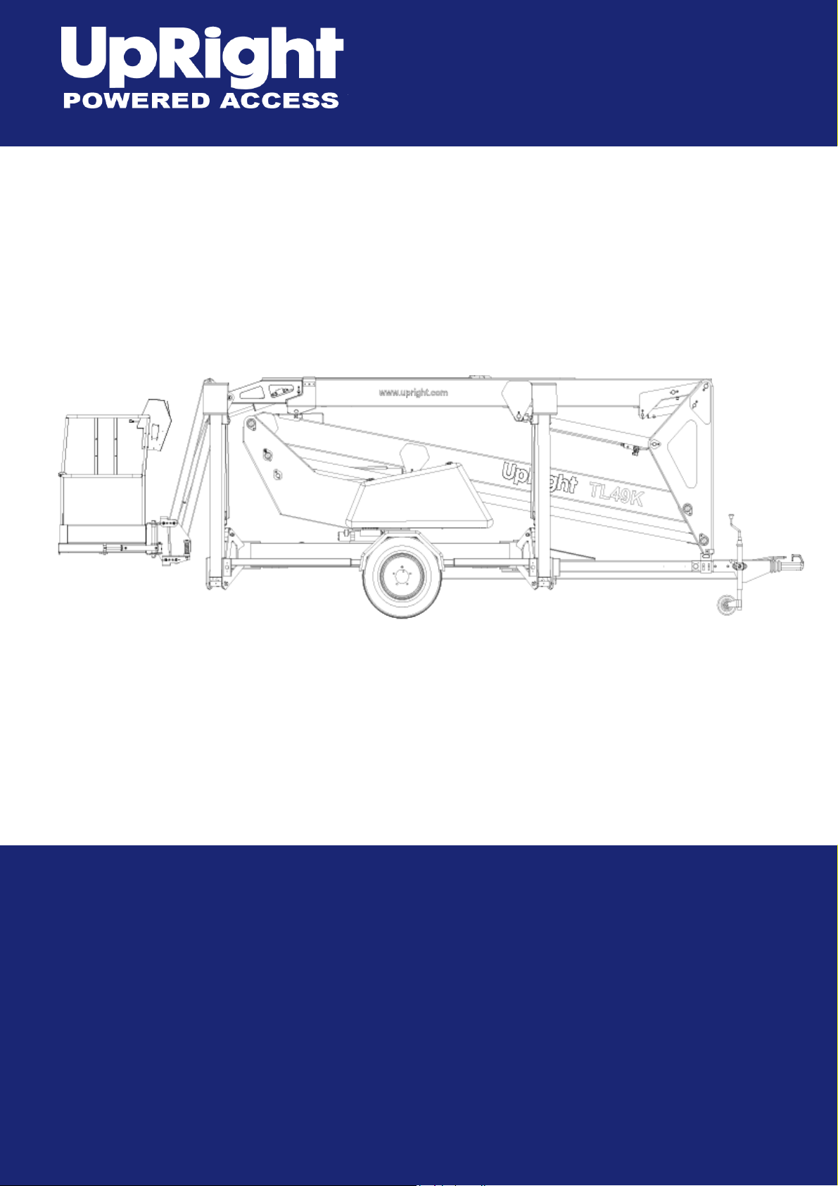
TL49K
Operator Manual
This first section of the Operator manual is the English language version.
Betriebsanleitung
Im zweiten Abschnitt dieser Betriebsanleitung finden Sie die Deutsche Version.
Manuel Utilisateur
La troisième section de ce manuel est la version en langue Française.
Manual del Usuario
El apartado cuarto de este manual del usuario corresponde a la versión en Españo.
Manuale d’Uso
La quinta sezione di questo manuale d'uso è la versione in lingua Italiana.
(EN) Manual part number 508159-000 for serial numbers 8000 to current.
(DE) Bestellnummer 508159-000 ab Seriennummer 8000 fortlaufend.
(FR) Manuel Pièce numéro 508159-000 pour numéro série 8000 jusqu'au
numéro courant.
(ES) El número de referencia para el manual es el 508159-000 para la números
de serie del 8000 hasta el actual.
(IT) Manuale Ricambi Numero 508159-000 per Numeri di Serie da 8000
all’attuale.
Feb 08
Page 2

Page 3
TL49K
Serial Numbers 8000 – Current
ENGLISH
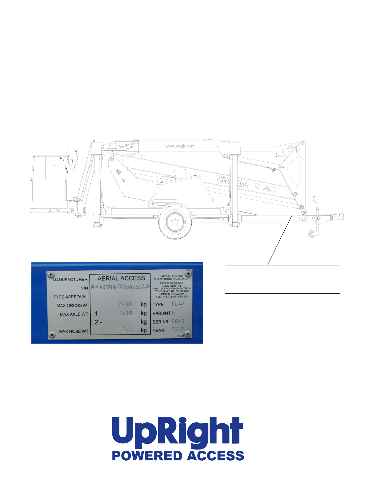
When contacting UpRight for service or parts information, be sure to include the MODEL and SERIAL NUMBERS
from the equipment nameplate. Should the nameplate be missing, the SERIAL NUMBER is also stamped on top of
the chassis bhind the toe hitch.
Serial number stamped on chassis behind the
toe hitch and above the Vehical Identification
Number Plate.
www.upright.com
Page 4

Page 5
p
,
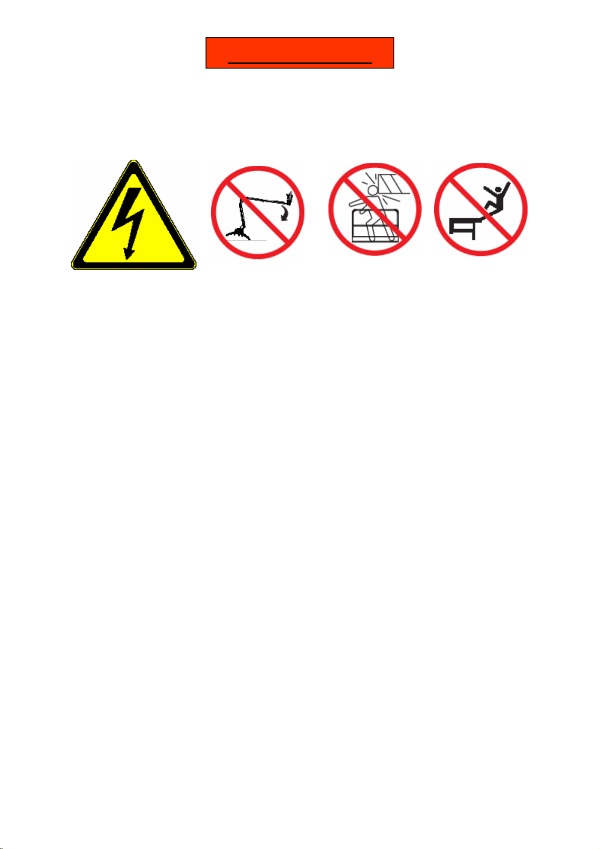
! WARNING !
Safety Rules
All personnel shall carefully read, understand and follow all safety rules and operating in-
structions before operating or performing maintenance on any UpRight aerial work platform
Electrocution Hazard Tip Over Hazard Collision Hazard Fall Hazard
NEVER
cl imb, stan d, or s it on
latfor m gua rd ra ils or mid ra i l.
This Machine is NOT
NE VER
elevate the platform or drive
t he mach ine w hile elevat ed u nless t he
machine is on a firm
le ve l sur f ac e .
NEVER
posi tion the p latform
witho ut first che cking for overhead
obstructions or other hazards.
Insulated
USE OF THE AERIAL WORK PLATFORM: This aerial work platform is intended to lift persons and his tools as
well as the material used for the job. It is designed for repair and assembly jobs and assignments at overhead
workplaces (ceilings, cranes, roof structures, buildings etc.). All other uses of the aerial work platform are prohibited!
THIS AERIAL WORK PLATFORM IS NOT INSULATED! For this reason it is imperative to keep a safe distance
from live parts of electrical equipment!
Exceeding the specified permissible maximum load is prohibited! See “Special Limitations” for details.
The use and operation of the aerial work platform as a lifting tool or a crane (lifting of loads from below upwards or
from up high on down) is prohibited!
NEVER exceed the manual force allowed for this machine. See “Special Limitations” for details.
DISTRIBUTE all platform loads evenly on the platform.
NEVER operate the machine without first surveying the work area for surface hazards such as holes, drop-offs,
bumps, curbs, or debris; and avoiding them.
OPERATE machine only on surfaces capable of supporting wheel loads.
NEVER operate the machine when wind speeds exceed this machine’s wind rating. See “Beaufort Scale” for de-
tails.
IN CASE OF EMERGENCY push EMERGENCY STOP switch to deactivate all powered functions.
IF ALARM SOUNDS while platform is elevated, STOP, carefully lower platform. Move machine to a firm, level
surface.
Climbing up the railing of the platform, standing on or stepping from the platform onto buildings, steel or prefab
concrete structures, etc., is prohibited!
Dismantling the swing gate or other railing components is prohibited! Always make certain that the swing
gate is closed and securely locked!
It is prohibited to keep the swing gate in an open position (held open with tie-straps) when the platform is raised!
To extend the height or the range by placing of ladders, scaffolds or similar devices on the platform is prohibited!
NEVER perform service on machine while platform is elevated without blocking elevating assembly.
INSPECT the machine thoroughly for cracked welds, loose or missing hardware, hydraulic leaks, loose wire con-
nections, and damaged cables or hoses before using.
VERIFY that all labels are in place and legible before using.
NEVER use a machine that is damaged, not functioning properly, or has damaged or missing labels.
To bypass any safety equipment is prohibited and presents a danger for the persons on the aerial work platform
and in its working range.
NEVER charge batteries near sparks or open flame. Charging batteries emit explosive hydrogen gas.
Modifications to the aerial work platform are prohibited or permissible only at the approval by
AFTER USE, secure the work platform from unauthorized use by turning both keyswitches off and removing key.
UpRight.
TL49K 508159-000
Page 6

CONTENTS
Page
Introduction 3
Description of Equipment 4
Technical Specification 5
Working Envelope 6
Operator Requirements 7
Warning Notices 8
. Beaufort Scale 9
Towing Instructions 10
Hand Manoeuvring (Friction Drive Option) 12
Pre-Start Checks 13
Power Supply 19
Batteries, & Power Pack 15
Setting Up 16
Extending Structure 18
. Basket Controls 18
. Ground Controls 20
Safety Harness 21
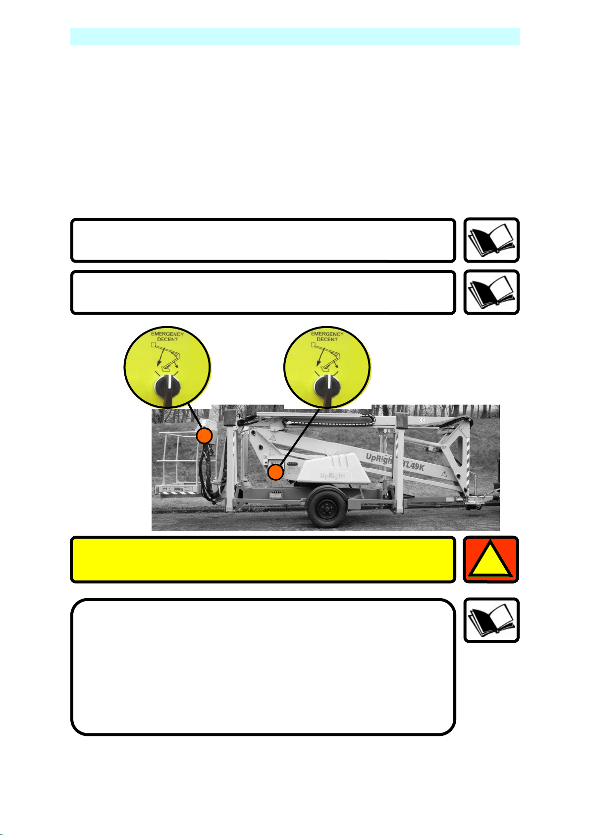
Emergency Controls
. Emergency Stops 21
. Emergency Lower (Electronically) 22
. Emergency Lower (Manually) 23
. Emergency Raise Outriggers 24
. Emergency Cage Overload 24
. Emergency Battery Isolation 25
Stowing the Machine 26
Maintenance
. Daily Checks 27
. Weekly and Monthly Checks 28
. Slew Drive and Limit Switches 29
. Trailer Lighting Diagram 30
Appendices
Petrol/Bi-fuel Option. 31
Generator Option. 32
Mains connection. 33
2 508159-000 TL49K
Page 7
INTRODUCTION
The UpRight TL49K is a class leader, offering several features as standard that
other manufacturers only provide as optional extras.
These include powered basket rotation and fully proportional hydraulic controls, at
both basket and ground level.
The third flick boom, with 130 DEGREES working arc, guarantees access to the
most hard to reach places, while the 90 DEGREES basket rotation provides the
precision positioning that is vital for working in tight spaces.
UpRight Powered Access has a global reputation for innovation and a proud
heritage in the design and manufacture of high quality powered access equipment.
The company was founded in the UK more than 25 years ago, on the principle of
constantly improving service excellence for end users.
Every model in our growing range of versatile, trailer mounted units is a class
leader and together they have set new industry benchmarks.
Our commitment to research and design, plus 250,000sq ft of same site
fabrication, build and support capacity, mean UpRight can offer complete solutions
to meet even the most demanding access applications.
UpRight has third party accreditation to quality standard ISO 9001 and the full
range carries the CE mark, complying with or exceeding all relevant standards and
EC directives.
UpRight Powered Access is a member of the
International Powered Access Federation (IPAF).
To ensure you are fully aware of safety and operational information, the
following symbols are used throughout this manual;
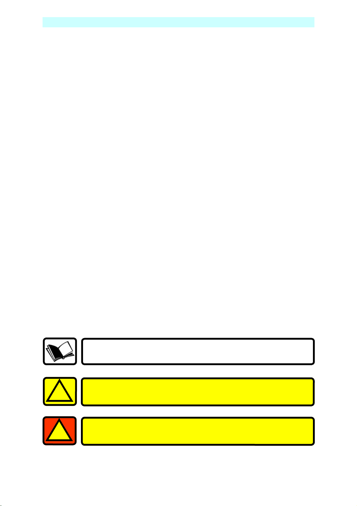
This type of box contains, Points of operation to NOTE.
The information contained in this type of box contains, WARNING
!
1
text. It gives Warnings about the risk of Damage to equipment,
and possibly personnel.
The information contained in this type of box contains, DANGER
text. It gives Warnings about the risk of PERSONAL INJURY to the
operator and or others.
TL49K 508159-000 3
Page 8

DESCRIPTION OF EQUIPMENT
The UpRight TL49K is of the parallel linkage vertical boom design, mounted on a
road towable trailer. The unique, yet very simple boom configuration gives the
maximum safety and control ability combined with a robust construction to
withstand a heavy working environment
The TL49K machine is designed for two man capacity (200 kg S.W.L.).
The machine incorporates a bottom boom with tie-rod, a short vertical boom and a
top boom with a telescope section. The TL49K also has an independent
hydraulically operated flick-out boom and rotating cage for extra manoeuvrability.
The hydraulic system is of a failsafe design throughout, with built in hydraulic lock
valves on all of the rams as a precaution against hose failure. The machine is
controlled by means of proportional manual controls of the ‘direct hand’ lever
operating type. These valves are located at both the base and in the cage, as
standard.
Electrically operated emergency lowering valves are fitted as standard to allow the
machine to be lowered from the base and basket.
The hydraulically operated outriggers are fitted with load sensing interlocks, to
prevent the booms from being raised without the outriggers being extended and
under load. An interlock prevents the hydraulic outriggers being accidentally
retracted while the booms are raised. A simple system of warning lights show the
power supply is on and each of the outriggers is under load.
Performance.
Maximum Working Height 17.00 m
Maximum Working Outreach: 9.10 m
Capacity (2 man working): 200 kg
Slewing Arc: 680°
Airborne Noise Emissions (Battery): 70 dB(A)
Construction Standards.
The machine complies fully with the requirements of the following EEC Directives:
Directive 98/37/EC – the ‘Machinery Directive’.
Directive 89/336/EEC – the ‘Electromagnetic Compatibility Directive’.
Directive 73/23/EEC – the ‘Low Voltage Directive’.
EN 6020-1/1993 ‘Safety of Machinery.’
The machine is designed and tested in accordance with all relevant B.S.I and
European Standards including EN280.
4 508159-000 TL49K
Page 9

TECHNICAL SPECIFICATION
Cage Dimensions
Length 1.20m
Width 0.80m
Guard-rail Height 1.10m
Toe-board Height 0.15m
Operating Dimensions
Maximum Working Height 17.00m
Maximum Cage Height 15.00m
Maximum Outreach ( From centre of rotation ) 9.10m
Travel Dimensions
Towing Length 7.10m
Closed Width 1.75m
Closed Height 2.10m
Weight (Battery Model) 2250 kg (un-laden)
(Battery Model + Friction Drive) 2395 kg (un-laden)
(Bi-fuel Model) 2300 kg (un-laden)
Operating Parameters
Safe Working Load 200 kg
Maximum Horizontal Pull 400N
Maximum Wind Speed 12.5 ms
Rotation 680°
Cage Slew 90°
Equipment
Bottom Ram Double acting: Bore Ø 80.0 mm
Rod Ø 50.0 mm
Top Ram Double acting: Bore Ø 80.0 mm
Rod Ø 50.0 mm
Tele’ Ram Double acting: Bore Ø 65.0 mm
Rod Ø 45.0 mm
Flick Ram Double acting: Bore Ø 60.0 mm
Rod Ø 40.0 mm
Stabiliser Ram Double acting: Bore Ø 70.0 mm
Rod Ø 40.0 mm
Bottom & Top Ram Lock Valves Pilot operated over centre valves
Control Valve (Cage) Monoblock unit consisting of seven
double acting spools
Control Valve (Ground) Monoblock unit consisting of five
double acting spools
Control Valve (Stabiliser) Monoblock unit consisting of four
double acting spools
Bushes Acetol resin polymer with sintered
bronze base (DX)
Pivot Pins Stainless Steel Bright Bar
To Grade BS970 303 S31 CW, &
MecaVal 147m, Tuftride TFI-AB1
coated.
-1
TL49K 508159-000 5
Page 10
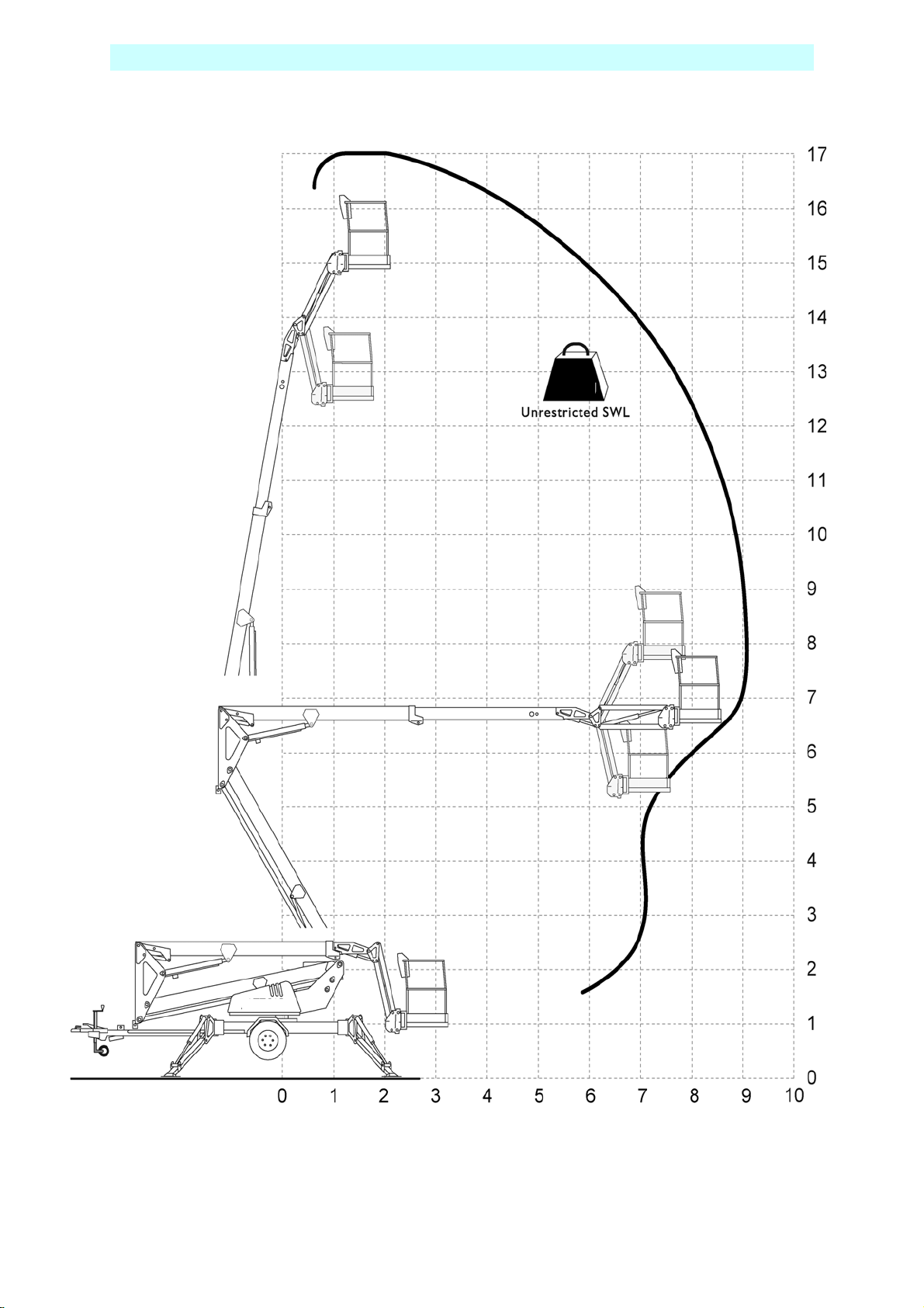
OPERATING ENVELOPE
200kg
Height and Distance in Metres.
6 508159-000 TL49K
Page 11

OPERATOR REQUIREMENTS
Please read this carefully, and ensure you have received the correct training
prior to operating this machine.
1. To operate the machine you must be medically fit and have no problems
with eyesight or hearing.
2. You must have a good head for heights.
3. Your primary concern must be the safe operation of the work platform, the
safety of the people working with you, and the safety of other persons in
your working area.
4. You must be familiar with the contents of this manual, and at no time
attempt to operate the machine beyond the recommended limits.
5. The proper care of the work platform is a major factor in ensuring the safety
of those who work with it.
6. You must not misuse the machine or ignore or interfere with the devices
that have been provided to maintain safety.
7. Operation of the machine should be restricted to personnel who have been
authorised to operate the equipment and have received proper training.
TL49K 508159-000 7
Page 12
WARNING NOTICES
1. DO NOT operate this machine unless you have been fully trained in its safe
use.
2. DO NOT operate the machine on soft, slippery or sloping ground unless
adequate precautions have been taken.
The stabilisers are designed to operate on firm level ground with a minimum
bearing strength of 50N/cm
The maximum load imposed by an outrigger is 12.5kN.
Advice should be obtained from UpRight as to the type of supports and
precautions required before attempting to operate the machine outside
these parameters.
3. DO NOT use any equipment in the basket to increase the reach or working
height of the machine, e.g. ladders.
4. DO NOT fit any additional equipment to the machine that would increase
the wind loading, e.g. notice boards.
5. DO NOT use the machine for any application that may produce special loads
or forces: the manufacturer, UpRight Powered Access, must be consulted for
approval of special applications prior to use.
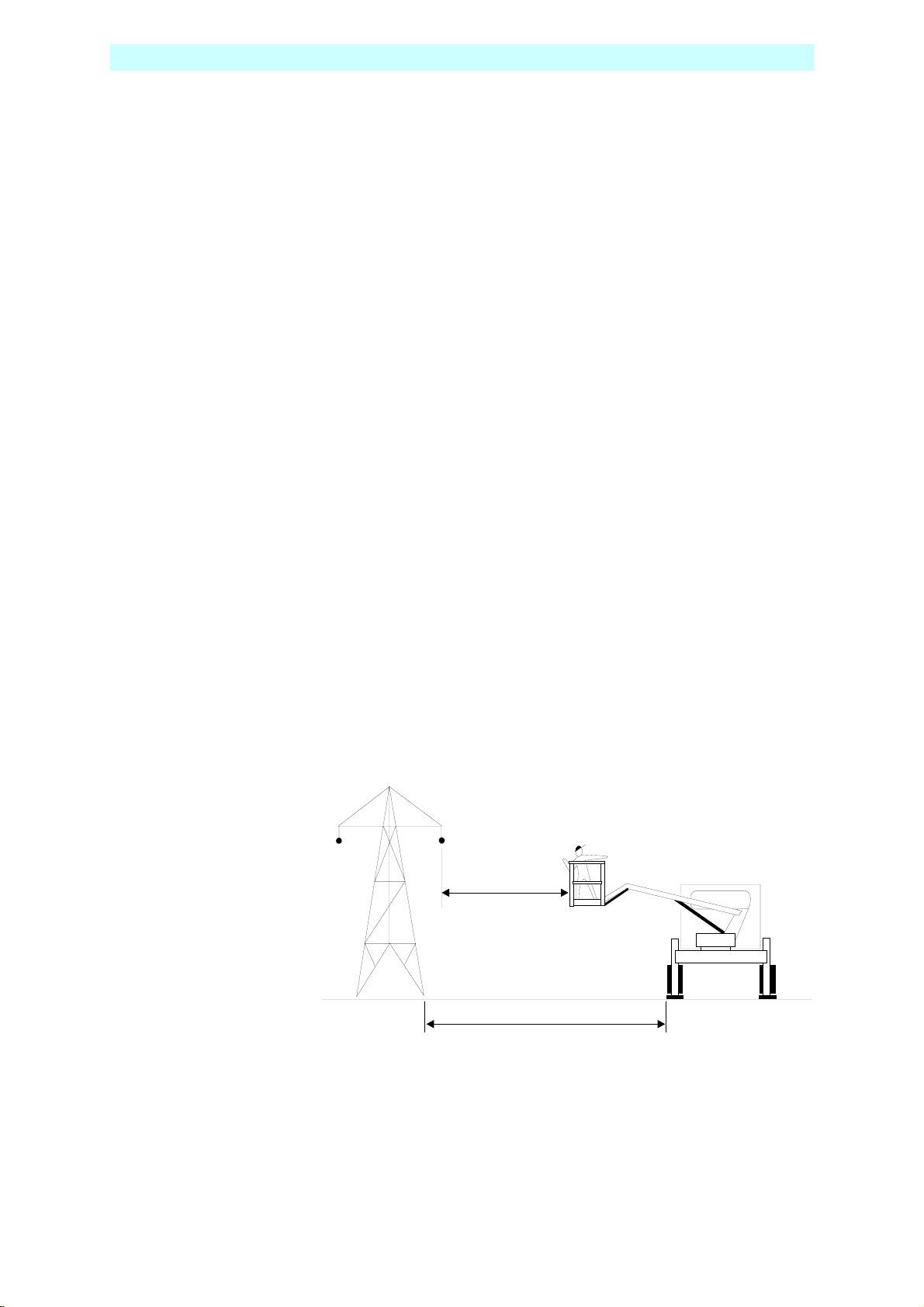
6. DO NOT use the machine close to live electrical conductors. The minimum
safe working distance for a machine working near overhead power cables is
the maximum extended length of the booms plus 15 metres, measured
with the booms pointing towards the lines, i.e. safe working distance for the
TL49K is 24 metres. It is the operator‘s responsibility to ensure that, when
working in the vicinity of live overhead high-voltage lines, the minimum safe
working distance is maintained. Erect a simple barrier tape at the safe
distance.
7. WORKING CLOSE TO POWER CABLES – if work has to be carried out at less
than the safe working distance, the operator must ensure that the
electricity supply has been switched off. Before commencing work, a
written permit to work must be obtained from the owners of the power
cables or the responsible authority.
2
.
15m
15m
24m
26m
8 508159-000 TL49K
Page 13
WARNING NOTICES
8. DO NOT operate the machine unless all four outriggers are down and in full
contact with the ground. The machine must be level and the wheels lifted
visibly clear of the surface before the booms are raised.
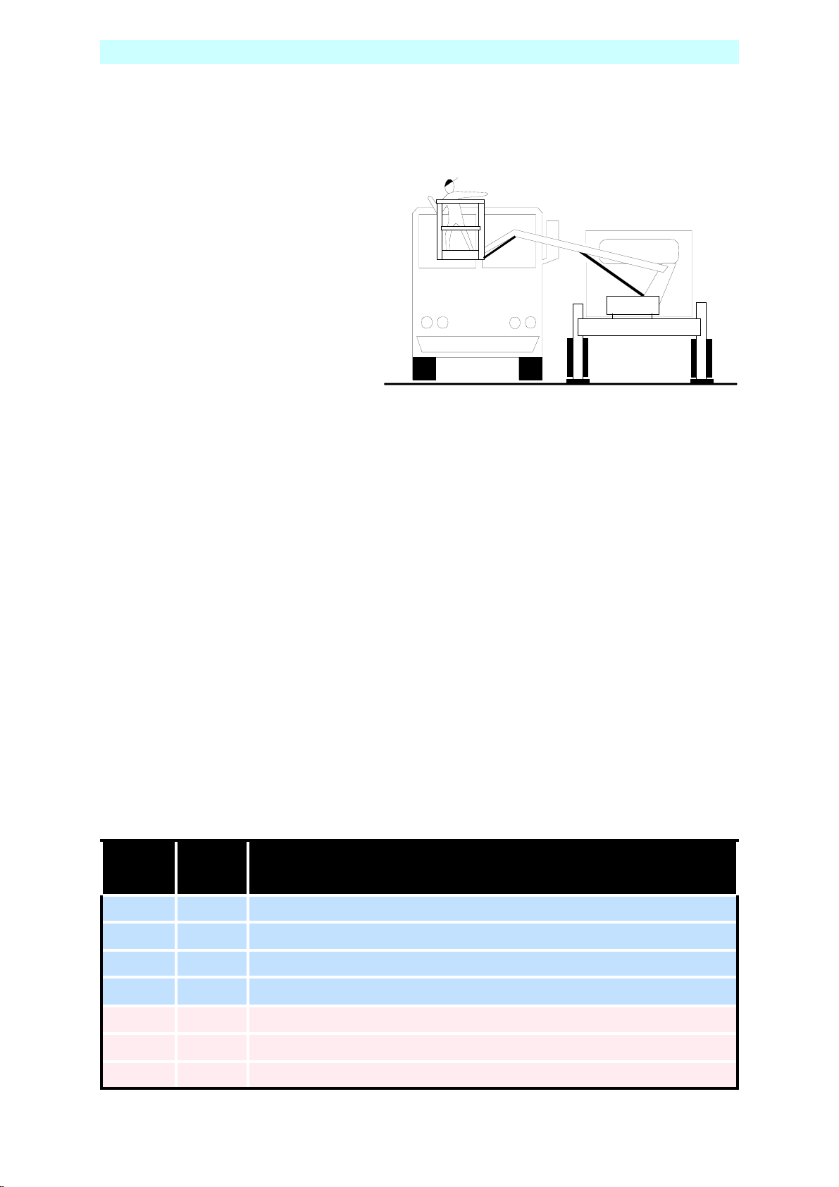
9. DO NOT move the machine
with the basket raised and
never allow cage or booms to
slew into the path of
oncoming vehicles.
10. DO NOT operate the machine if the wind speed exceeds 12.5 m/s. Be aware
that, when working near high buildings or structures, shielding and
funnelling effects may cause high wind forces on days when the nominal
wind speed in the open is low. Wind speed can either be measured from
the work platform with a hand held anemometer or estimated using the
Beaufort Scale.
BEAUFORT WIND SPEED SCALE
The Beaufort Scale of wi nd force is accepted internationally and is used in communicating weather
conditions. It consists of numbers 0 - 12, each representing a certain strength of velocity of wind at
10m (33ft.) above ground in t he o pen .
Approximate corrections for wind speeds at other heights are:
2m subtract 30%;
3m subtract 20%;
6m subtract 10%
15m add 10%;
30m add 25%
Beaufort
M/Sec Ground Conditions
Scale
3 3.5-5
4 6-8
5 9-10
6 11-13
7 14-17
8 18-21
9 22-24
TL49K 508159-000 9
Leaves and small twigs in constant motion; wind extends light flag.
Raises dust and loose paper; small branches are moved.
Small trees in leaf begin to sway; crested wavelets on inland waterways.
Large branches in motion; umbrellas used with difficulty.
Whole trees in motion; inconvenience felt when walking against wind.
Breaks twigs off trees; generally impedes progress.
Slight structural damage occurs (chimney pots and slates removed)
Page 14
Right
Up
g
h
h
L
4
L
4
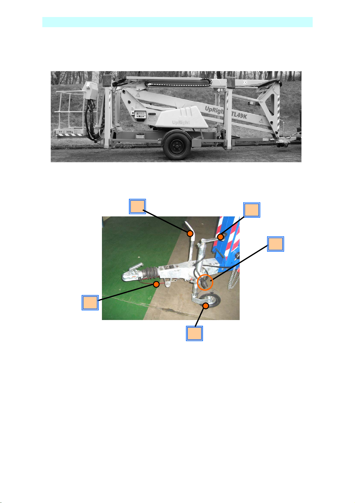
TOWING INSTRUCTIONS
Trailer mounted machines are fitted with suspension units that may be safely
towed behind a car or van at speeds of up 50mph (80km/h) where permitted.
1. Before towing, check the capacity of the vehicle being used.
(Machine weight will increase if optional extras are fitted)
2. Ensure that the road tyres and brakes are in good, serviceable condition.
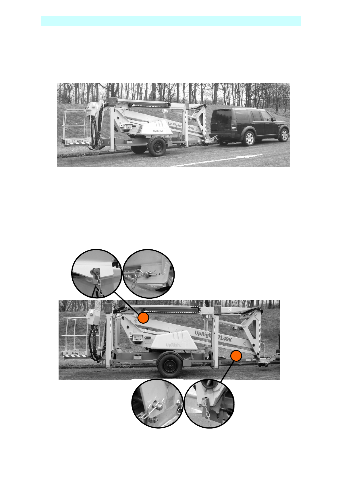
3. Ensure that all booms are fully lowered and both the transit pins are fitted
through the loops and secured with the “R” clip on the end of the chain.
10 508159-000 TL49K
Page 15
R ight
g
h
h
L
4
L
4
TOWING INSTRUCTIONS
4. Ensure that all outriggers are fully raised.
5. Use the Jockey Wheel to raise or lower the tow bar coupling to position the
machine above the 50mm ball hitch on the towing vehicle.
8
6. Apply the handbrake.
7. Lower the tow bar coupling down onto the ball hitch using the Jockey Wheel
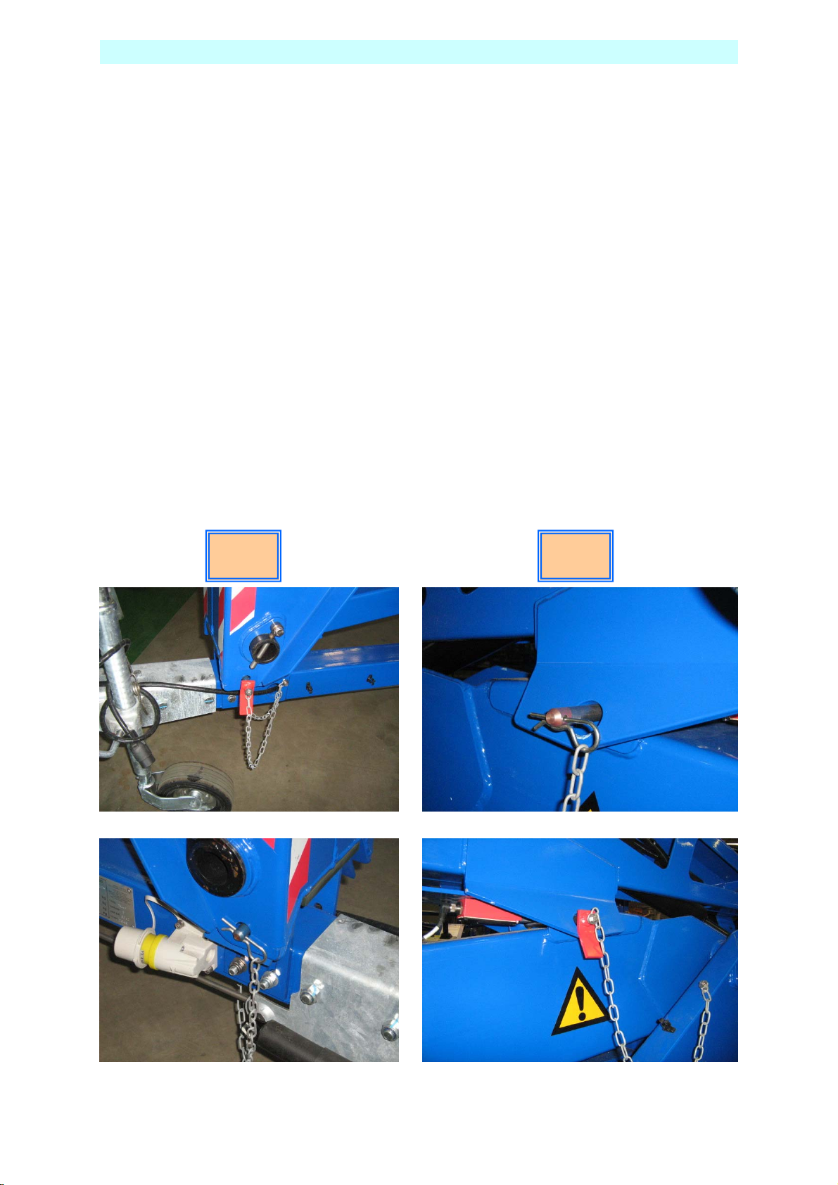
8. Secure the breakaway cable,
(Ensure correct engagement of 50mm ball).
9. Fully raise the Jockey Wheel and lock in position.
10. Release the Handbrake.
11. Plug in the trailer lights (7 pin plug) and check that both vehicle and trailer
lights operate correctly.
6
7
11
9
TL49K 508159-000 11
Page 16
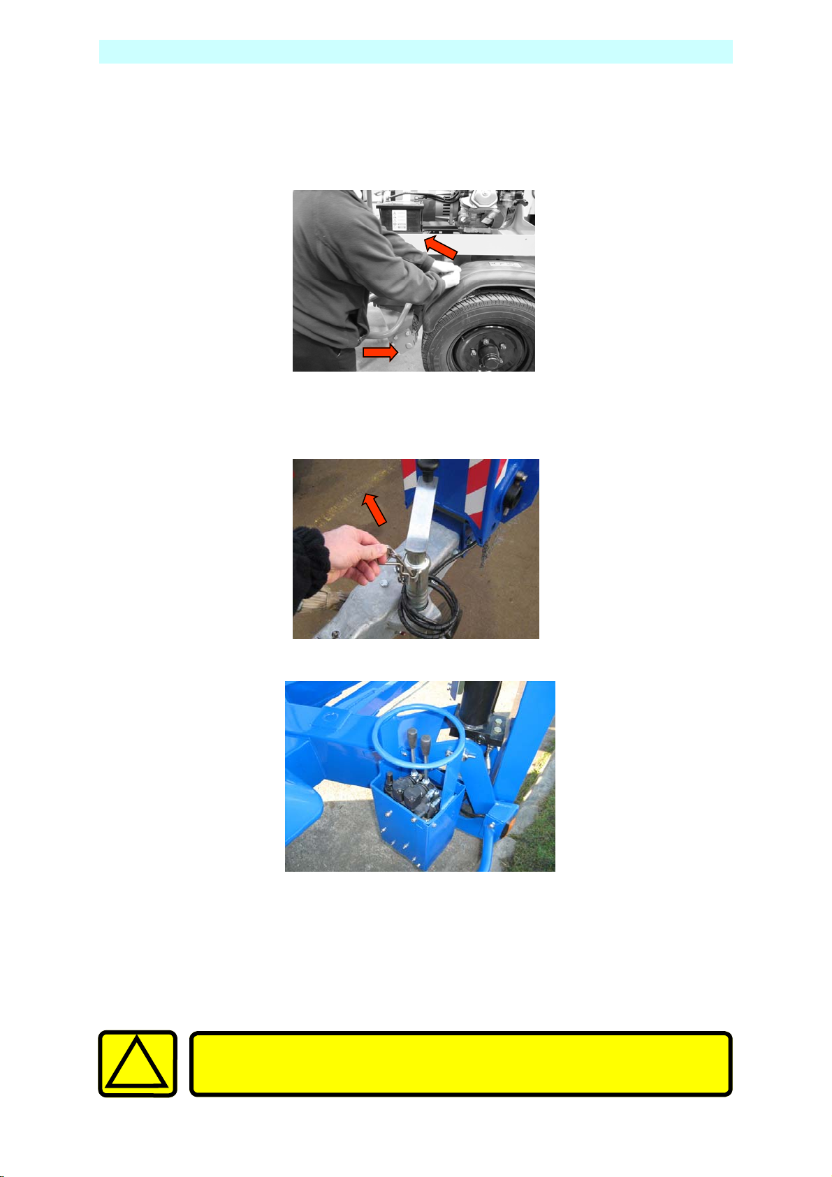
HAND MANOEUVERING (Optional)
1. Ensure that the booms are fully lowered, all outriggers are fully raised
and the machine is in a menoeverable condition.
2. Engage the the friction drive cylinders against the trailer tyres by pulling
actuating levers forward and down until they lock overcentre.
3. Ensure the power selector switch is set to Base.
4. Disengage the handbrake, and ensure that the Jockey wheel directional
locking pin is removed
5. Traction is controlled via the 2 hydraulic levers on the R/H side of the
chassis.
6. The left lever controls the left motor and the right lever the right.
Operating only the left lever forward will turn the machine right and the
right lever will turn the machine left, operate both levers together for
parallel drive.
7. When the machine is in position replace handbrake.
Ensure friction drive cylinders are disengaged prior to platform
!
12 508159-000 TL49K
operation or towing.
Page 17
R ight
g
h
h
L
4
L
4
PRE-START CHECKS
The following Pre-Start Checks should be carried out before taking the
machine to the place of work.
1. Damaged or Loose Fittings.
Visually Inspect the machine for signs of wear and tear, damage, loose or
missing parts.
2. Wheels. (For towing only)
Check tyres are at the correct pressure, TL49K = 76psi (5.25 bar).
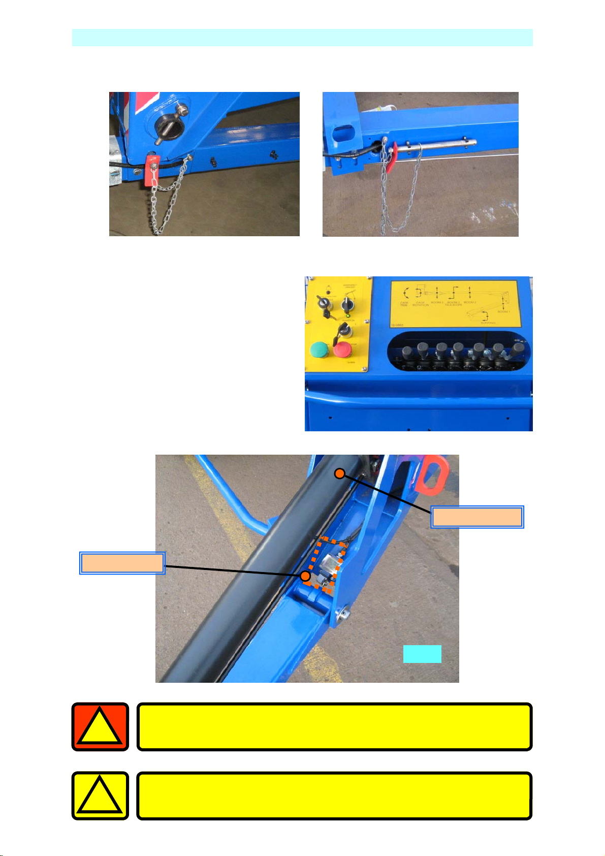
3. Hydraulic fluid.
The hydraulic oil tank is located underneath the slew cover on the right
hand side of the machine (looking from the cage end), Ref, Fig.2, section J
With the booms and outriggers in the transport position, the hydraulic oil
level should be visible between the upper and lower marks of the
Sight Glass.
Top up with ISO Grade 22 hydraulic oil if necessary.
Do Not Overfill the Tank
Serious injury or even death may result by not carrying out the
following checks of the interlock system before the platform is
used!
4. Safety Switches.
Visually check the cage overload switch is free from damage.
Check all limit switch arms are free from damage and move easily
(outrigger switches shown in Fig.6 ).
With outriggers in transport position, it must not be possible to operate the
extending structure. With outriggers deployed, under load and top or
bottom boom raised approximately 50mm, it must not be possible to
operate the outrigger controls.
The flick boom is not interlocked with the outriggers.
1
TL49K 508159-000 13
Page 18

PRE-START CHECKS
5. Emergency Stop Switches.
Emergency stop switches must operate correctly. Check that each stops the
machine’s controls and that restarting is prevented until all stop switches
are unlatched.
6. Emergency Lower/Slew.
With the top and bottom booms raised approximately 500mm each and the
unit switched off, check:
The emergency lower switch located in the basket and ground control
stations, lowers the booms when operated.
The emergency slew, telescopic boom retraction can be operated by using
the hand pump and control lever at the ground control station.
To Reset the hydraulic system after checks;
Fully slew the Basket to the right, so that he ram is fully extended.
Fully extend the Outriggers while still maintaining Level. (check the bubble)
Using the ground controls, fully extend Top, Bottom and Telescopic Booms.
Fully extend the Flick Out Boom.
All rams must be fully extended at the same time before returning them to
their transit position.
If the Emergency Lower is used during normal operation, DO NOT
use the machine, Contact your local UpRight representative.
7. Emergency Hand Pump.
With the unit set up for working (i.e. outriggers down, under load and the
machine level with wheels clear of ground) it is possible to lower the cage
using the emergency hand pump.
8. Battery Power (Where applicable)
Check batteries are fully charged and topped up with distilled water (these
are fitted under the slew cover on both sides of the platform).
Hydrometer reading should be 1280-1320sg.
With machine level, the distilled water should cover the plates by
approximately 6mm.
9. Mains Power (Where applicable)
Check that the voltage and frequency of the power input matches that of the
motor. All extensions must be a minimum of 2.5mm², and no longer than
10m due to possible voltage drop.
10. Petrol/diesel Power (Where applicable)
Check that there is sufficient oil and fuel to complete a full working shift.
14 508159-000 TL49K
Page 19
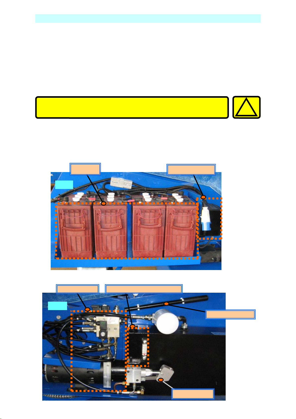
BATTERIES & POWER PACK
Battery Power, 24V DC.
Ensure batteries have been fully charged before use and that the Battery Isolating
Plug is securely connected.
Mains Power, (OPTIONAL)
Connect the mains supply, either 110V or 220/240V A.C., depending upon the
motor specification. Check the motor is running when the key is turned to the ON
position.
All extensions must be a minimum of 2.5mm², and no longer than
10m, due to possible voltage drop, which will damage the motor.
Petrol/diesel Power, (OPTIONAL)
Check the fuel and oil levels of the engine. Switch on the ignition using the key
switch on the slew mounted legend panel. Check the engine runs using the start
and stop buttons in the basket.
!
Fig. 1
Power Pack
Fig. 2
Batteries
Battery Charger
Oil Filler and Sight Glass
Pump Handle
Hand Pump
TL49K 508159-000 15
Page 20
SETTING UP
1. Park the unit in an appropriate location at the workplace.
Do not attempt to set up the machine on steep slopes, ramps or
soft ground.
2. Apply the handbrake on the trailer and remove from the towing vehicle.
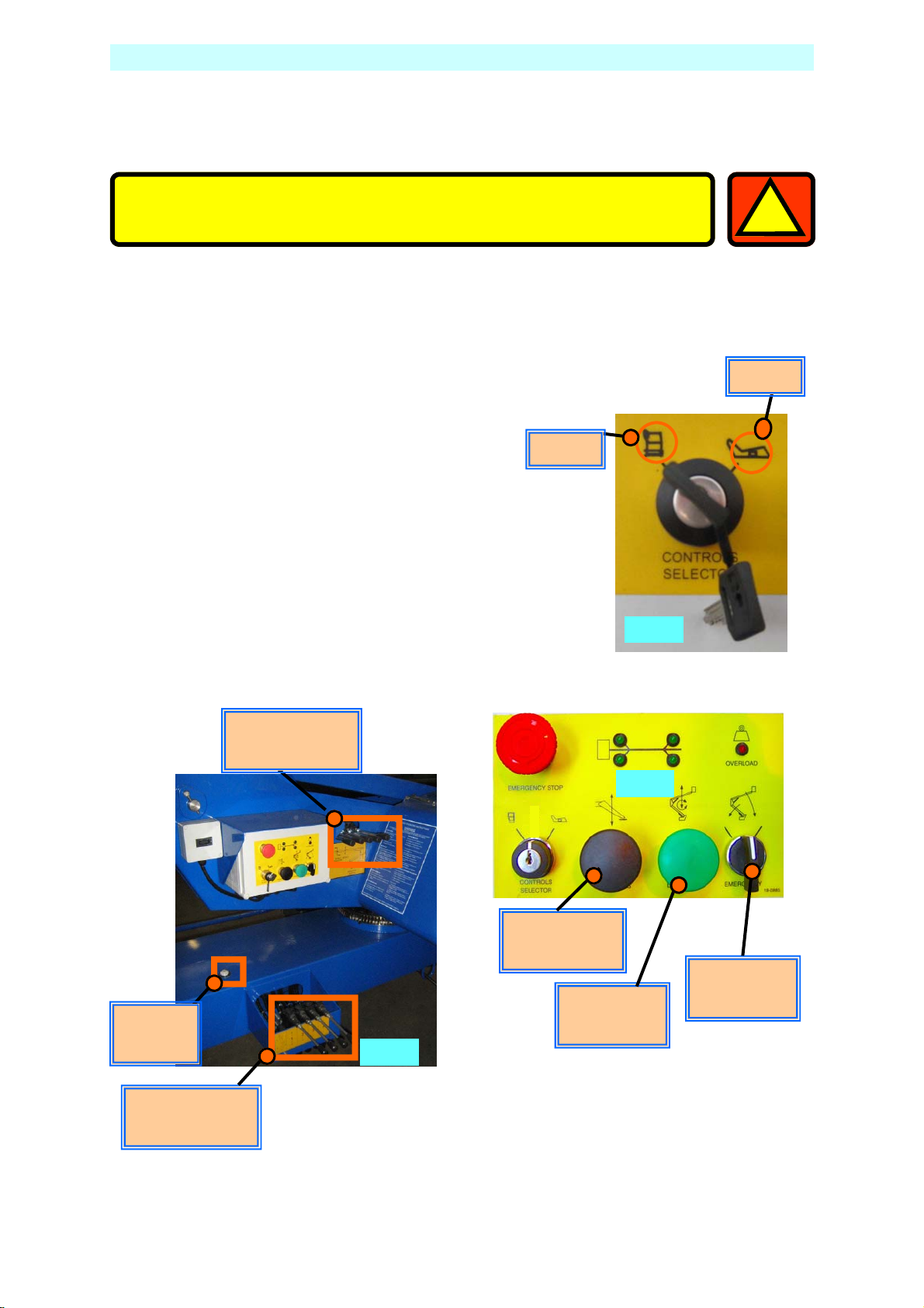
3. With platform key switch set to ’Ground’ (Fig 3)
lower the outriggers by keeping the
‘Outrigger Motor Run’ button (Fig 4)
pushed in, operate the appropriate
‘Outrigger control lever’ (Fig 5), until all
four are 25mm to 50mm from the
ground.
Basket
1
Ground
Level
indicator
Control Levers
Ground
Fig. 5
Motor Run
Outrigger
Motor Run
Booms
Fig. 3
Fig. 4
Emergency
Lower
Control Levers
Outriggers
16 508159-000 TL49K
Page 21

SETTING UP
4. Lower the Outriggers two at a time starting at the tow bar end (No’s 3&4) until
the jockey wheel just clears the ground.
5. Lower Outriggers 1&2 until the green LED display indicates that they are
under load. (As shown below)
Take EXTREME care NOT to ground either the Basket, or the
!
6. Repeat this sequence for Outriggers 3&4.
7. By alternating from 1&2 to 3&4, carefully inch down each pair of Outriggers
until all four Outriggers are fully deployed, and the wheels are well clear of
the ground.
8. Now, by using the Level indicator (Fig.5), raise opposite Outriggers until the
bubble and indicator ring are concentric (i.e., the bubble rests in the centre).
9. Check that each LED on the Ground Control panel is still illuminated. This
indicates that each foot is in firm contact with the supporting surface.
1
Jockey Wheel during the next step.
The unit is designed to operate on a supporting surface of
minimum bearing strength of 50N/cm
2
.
The maximum outrigger load is 12.5kN.
1
TL49K 508159-000 17
Page 22
EXTENDING STRUCTURE
1. Remove and correctly stow the Transit Pins, from both the Upper and Lower
Booms.
2. At the Ground Control Station, turn the key to ‘Basket’. (See Fig. 3)
3.
Climb into the basket. Check that
all Emergency Stop Switches are
released (twist release). The platform may now be raised, lowered
or slewed in any direction by operating the control levers at the
basket, whilst depressing the motor run button (DEADMAN).
Limit Switch
Before raising, ensure there are no overhead obstructions or
1
!
power cables and the outriggers are properly extended and
secure.
Take EXTREME care when slewing both basket and turret, at low
levels.
Outrigger Ram
Fig. 6
18 508159-000 TL49K
Page 23
EXTENDING STRUCTURE
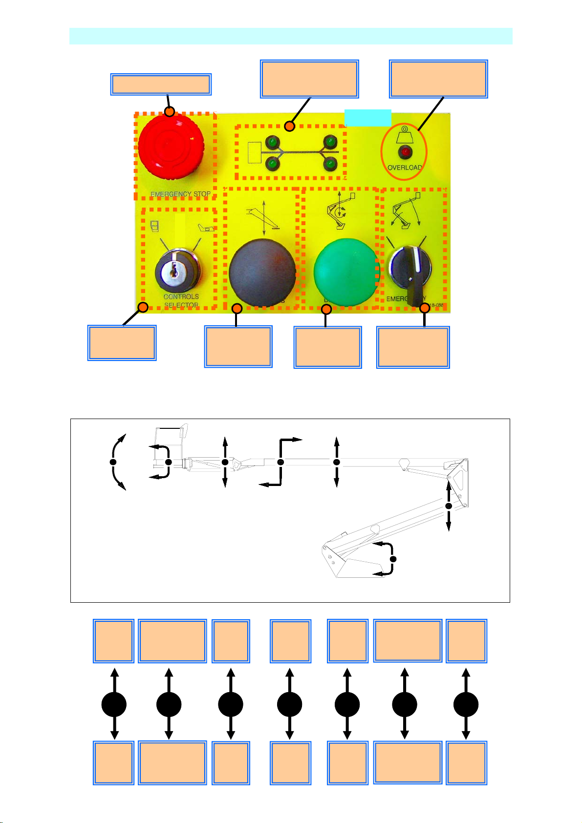
Emergency Stop
Control
Selector
Motor Run
Outriggers
Outrigger Load
Indicators
Motor Run
Booms
Basket overload
Indicator
Fig. 4a
Emergency
Lower
4. Explanation of the Basket Control Station, Directional Control Levers.
CAGE
TRIM
18-0865-02
Raise
Basket
Trim
CAGE
ROTATION
Slew
Basket
Anticlockwise
Raise
Flick
Boom
BOOM 2
TELESCOPE
Retract
Tele-
Boom
BOOM 2BOOM 3
Raise
Tele-
Boom
SLEWING
Slew
Turret
Anticlockwise
BOOM 1
Raise
Lower
Boom
Lower
Basket
Trim
Slew
Basket
Clockwise
Lower
Flick
Boom
Extend
Tele-
Boom
Lower
Tele-
Boom
Slew
Turret
Clockwise
Lower
Lower
Boom
TL49K 508159-000 19
Page 24
EXTENDING STRUCTURE
5. A duplicate set of controls (excluding Slew Basket) is mounted on the Slew
Turret under the right hand side cover, which allows the platform to be
operated from the Ground.
6. At the Ground Control Station, turn the key to ‘Ground’. (See Fig.3)
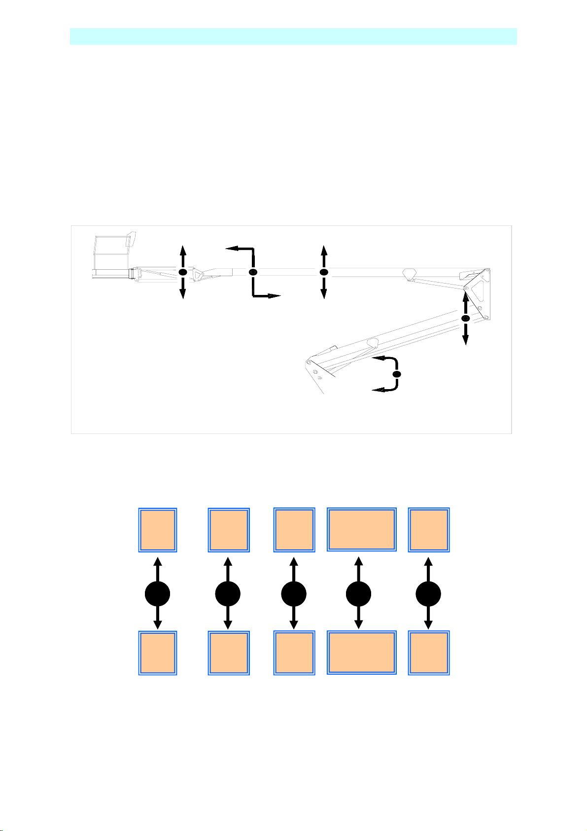
7. Explanation of the Ground Control Station, Directional Control Levers
18-0884
Raise
Flick
Boom
BOOM 2
TELESCOPE
Extend
Tele-
Boom
BOOM 2BOOM 3
Raise
Tele-
Boom
SLEW ING
Slew
Turret
Anticlockwise
BOOM 1
Raise
Lower
Boom
Lower
Flick
Boom
Retract
Tele-
Boom
Lower
Tele-
Boom
Slew
Turret
Clockwise
Lower
Lower
Boom
20 508159-000 TL49K
Page 25

g
h
h
L
4
L
49
Right
g
h
h
L
4
L
4
SAFETY
Safety Harness
1. In accordance with IPAF recommendations, UpRight recommend the use of a Full
Body Harness with an adjustable lanyard is used when operation from the basket.
2. The lanyard length should be as short as possible.
3. A permanent attachment point is provided in the basket for fixing the harness.
EMERGENCY CONTROLS
1. Emergency Stop
Emergency Stop buttons are fitted on the machine to stop the motor in an
emergency.
There are 2 Emergency Stop Buttons, one in the basket, and one on the
ground control panel.
The emergency stops are ‘Reset’ by twisting.
TL49K 508159-000 21
Page 26
Right
g
h
h
L
4
L
4
EMERGENCY CONTROLS
Emergency Lower.
In the event of a power failure, There are two ways of Safely lowe ring the
basket.
2. Emergency Lowering, method one
The operator or someone on the ground, can lower the booms to a safe
position by activating the Emergency lowering selector switch both ways, o n
the Basket Control Panel and the Ground Control Panel.
The Flick Boom cannot be lowered by activating the Emergency
Lowering Switch.
The Emergency lowering valve will automatically close when the
switch is released.
If the Emergency Lower is used due to a machine defect, DO NOT use
the machine, Contact your local UpRight representative.
If the Emergency Lower is used, The TOP and BOTTOM BOOMS must
be fully extended then fully lowered before work can continue.
After Emergency lowering, any further POWERED lowering could
cause an AIRLOCK in the hydraulic system.
This could cause the Hydraulic operations to Fail.
ALL BOOMS MUST BE FULLY EXTENDED/RAISED, THEN LOWERED
BEFORE WORK CAN RECOMMENCE.
1
22 508159-000 TL49K
Page 27
EMERGENCY CONTROLS
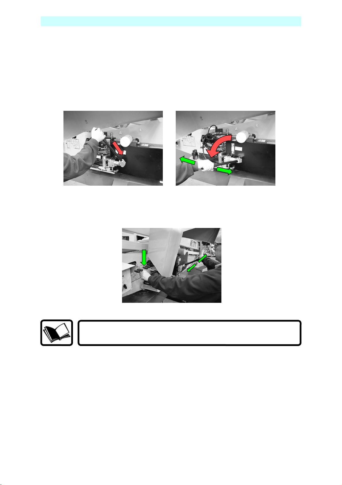
3. Emergency Lowering a, method two.
You can operate the hand pump from the ground control station cage
and operate the boom controls and slewing functions.
To operate the hand pump, insert the lever over the pump shaft, then lower
the lever to a convenient position to start pumping.
Move a control lever to the required direction of movement, and
operate the hand pump. When the machine starts to lower, continue
depressing the control lever.
Vigorous pumping is required to lower and slew the machine.
TL49K 508159-000 23
Page 28
EMERGENCY CONTROLS
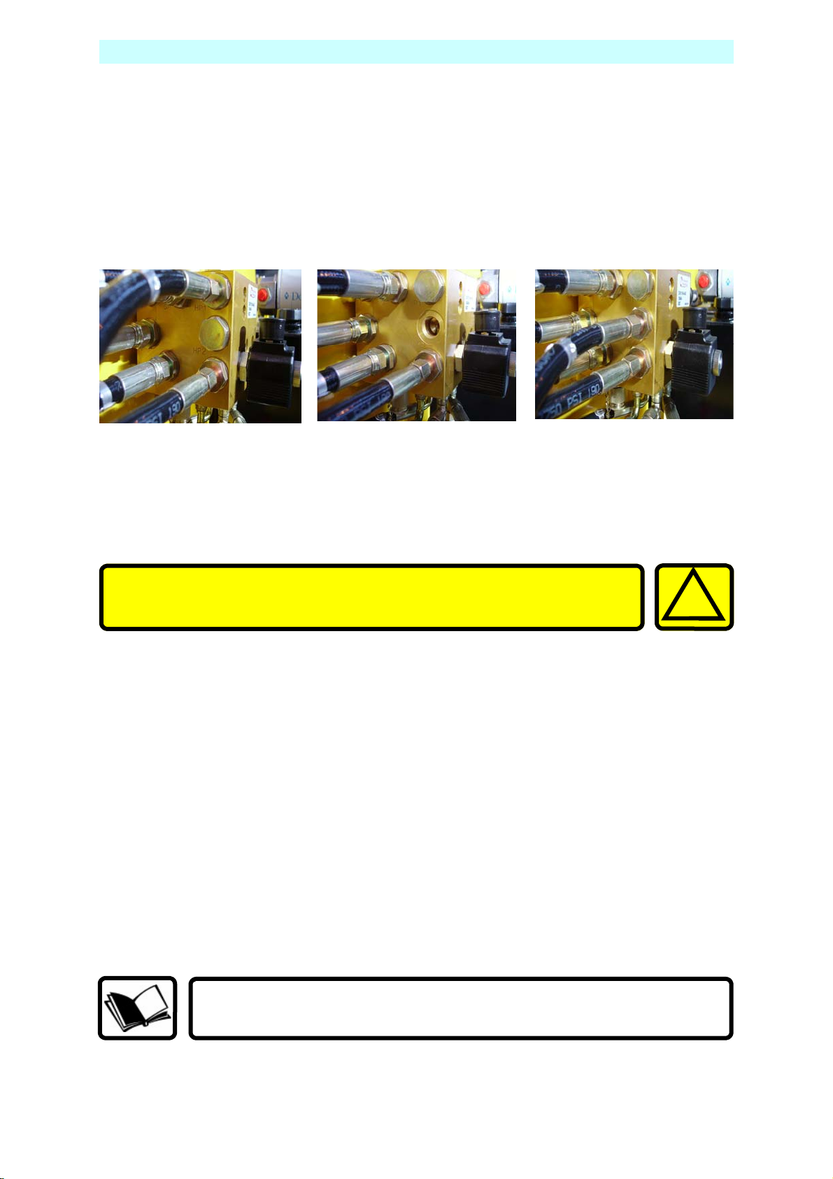
4. Emergency Procedure, Manual Raising of Outriggers.
In the event of power failure, the outriggers can be raised to their transport
position.
First the hand pump hose fitted to port HP1, must be redirected from HP1,
to port HP2, and the blanking plug from HP2 must be replaced into HP1,
using a 22mm spanner.
Once connected, move an Outrigger Control Lever in the required
direction of movement, and operate the hand pump. When the Outrigger
starts to raise, continue depressing the control lever.
Some hydraulic oil will be lost during this procedure. This will
still allow Emergency operations, but will need to be replaced
before full normal use can resumed.
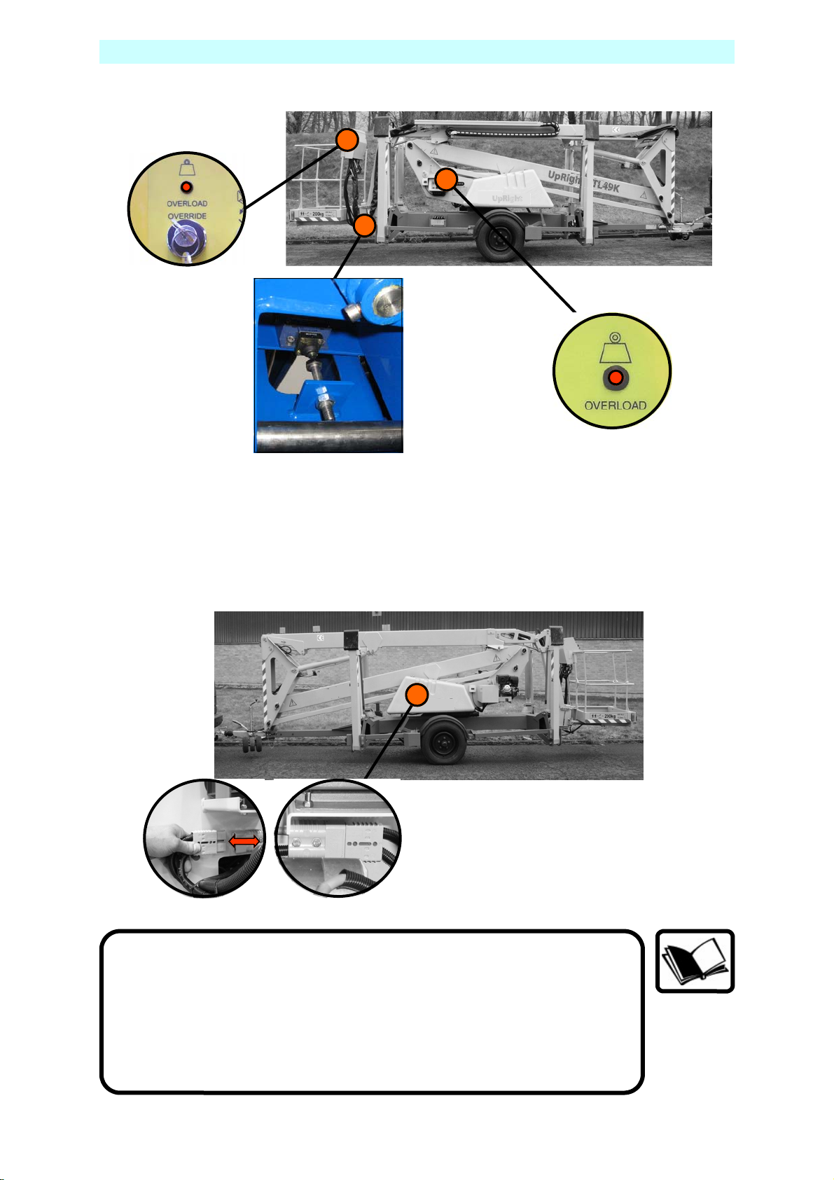
5. Cage Overload
In the event of the cage being overloaded, an audible alarm will sound and
the cage controls will cut out.
To re-start, enough load must be removed from the cage so that the
alarm stops sounding.
In cases where the overload can not be immediatley removed or the cage
has fouled, then the overload override selector switch can be used to move
the platform to a safe position so that the overload can safely removed.
!
The Key, Motor Run/Deadman and a Control Lever must be
operated at the same time to effect this action
24 508159-000 TL49K
Page 29
Right
g
h
h
L
4
L
4
EMERGENCY CONTROLS
6. Emergency Battery Isolating Plug.
Disconnecting this plug will isolate the batteries from the powerpack
and operating circuits.
Before operating this machine, it is important that both the
Operator and another responsible person on site, is aware of the
position and function of the following:
A) Emergency Stop Buttons.
B) Emergency Lowering Buttons.
C) Emergency Slew Drive Shaft.
D) Battery Isolating Plug.
TL49K 508159-000 25
Page 30
STOWING THE MACHINE
1. Fully lower all the booms.
2. Engage the Transit Pins, and lock in place using ‘R’ clip.
3. With platform keyswitch set to ‘Ground’:
Raise the outriggers by simultaneously depressing the ‘MOTOR RUN
Outrigger’ button and using the appropriate control levers, two at a time,
alternating between the cage and tow bar end until the road wheels are in
contact with the ground.
Only when the road wheels are in contact with the ground should the unit be
lowered further until the jockey wheel makes contact with the supporting
surface.
Now fully raise the outriggers until they are in the stowed position.
Switch off the platform and ensure all loose items/covers are secure before
towing the unit.
The machine is now ready for transportation.
TRANSPORT PIN LOCATIONS – SHOWN READY FOR TRANSPORT
Lower
Boom
Upper
Boom
26 508159-000 TL49K
Page 31

MAINTENANCE
The unit must have a thorough inspection carried out every 6
months in accordance with LOLER Regulations 1998 and a
Certificate of Thorough Inspection produced by a competent
person.
Always ensure the machine structure is in good, sound,
undamaged condition. Any inspection procedure is always aided
by keeping the machine clean. NB. Do not steam clean the battery
charger or electrical components.
Daily Checks.
1. Damaged or Loose Fittings.
Visually Inspect the machine for signs of wear and tear, damage, loose or
missing parts.
2. Wheels.
Check tyres are at the correct pressure, TL49K = 76psi (5.25 bar).
3. Hydraulic fluid.
The hydraulic oil tank is located underneath the slew cover on the left
hand side of the machine (looking from the cage end), Ref, Fig.2, section J.
With the booms and outriggers in the transport position, the hydraulic oil
level should be visible between the upper and lower marks of the
dipstick.
1
!
Do Not Overfill the Tank
Top up with ISO Grade 22 hydraulic oil if necessary.
4. Safety Switches.
Check all limit switch arms are free from damage and move easily
outrigger switches.
With outriggers in transport position, it must not be possible to operate the
extending structure.
With outriggers deployed, under load and top or bottom boom raised
approximately 50mm, it must NOT be possible to operate the outrigger
controls.
The flick boom is not interlocked with the outriggers.
5. Emergency Stop Switches.
Emergency stop switches must operate correctly. Check that each stops the
machine’s controls and that restarting is prevented until all stop switches
are unlatched.
TL49K 508159-000 27
Page 32

MAINTENANCE
The unit must have a thorough inspection carried out every 6
1
!
1. Apply grease to the slew gear wheel and all grease nipples.
2. From the Ground controls, Fully extend the Telescipic Boom and visually
inspect along its entire length for signs of wear and tear damage or
deformation.
3. Check battery acid level, top up with distilled water if required (maximum
6mm over plates when battery is standing level), and check mains cable
wiring.
1. Thorough inspection to be carried out by a competent person.(LOLER)
Weekly Checks.
Monthly Checks.
months in accordance with LOLER Regulations 1998 and a
Certificate of Thorough Inspection produced by a competent
person.
Always ensure the machine structure is in good, sound,
undamaged condition. Any inspection procedure is always aided
by keeping the machine clean. NB. Do not steam clean the battery
charger or electrical components.
FOR ENGINE MAINTENANCE REFER TO MANUFACTURES GUIDELINES
28 508159-000 TL49K
Page 33

MAINTENANCE
Slew Drive Gears.
The slew drive gear is designed to be largely maintenance free. However, we
recommend the gear teeth be greased on a monthly basis with a high pressure
grease. Additionally, the ring gear and gear box should be greased on a six
monthly basis. The grease nipple for the ring gear is on the top face of the slew
gear, set between the fixing bolts. It can be accessed by lifting one of the side
covers, and slewing the structure appropriately.
The ring gear should be inspected on a six monthly basis for excessive play. It is
unlikely there will be any wear if the machine is maintained correctly.
To check the gear, place a payload of approximately 80Kg in the platform. Elevate
the lower boom to approximately half way. Then gently elevate the top boom,
whilst observing the ring gear. Excessive wear will be observed by noticing more
than 0.5mm movement between the inner and outer bearing rings.
Checking Limit Switch Operation.
The limit switches require no maintenance, other than a visual inspection, on a pre
operation basis. This is an important check, to ensure the switch is not
mechanically damaged, and the roller is always in contact with the cam, when not
under load.
The switch operation can be simply checked, by observing the LED display when
deploying the stabilizers. As an outrigger foot touches the ground and becomes
loaded, the appropriate light will change to green. This indicates that the switch
contact has operated correctly.
Outriggers
under load
If the LED displays green at any other time then the machine must not be operated,
until the fault is rectified.
Grease
Nipple
Grease
Nipples
Outriggers NOT
under load
TL49K 508159-000 29
Page 34

MAINTENANCE
Pin No. Ref. Colour Function
1
2
3
4
5
6
7
L YELLOW L.H.INDICATOR
54G BLUE FOG LIGHT(S)
31 WHITE EARTH
R GREEN R.H. INDICATOR
58R BROWN R.H. TAIL, No. PLATE & MARKER LIGHTS
54 RED STOP LIGHT
58L BLACK L.H. TAIL, No. PLATE & MARKER LIGHTS
30 508159-000 TL49K
Page 35

APPENDIX Bi-Fuel Option
This machine variant is fitted with a petrol/diesel engine, with remote start
and stop
Diesel Engine
This manual does not cover the maintenance of the engine.
For engine maintenance details refer to the manufacturers handbook.
Prior to operating the engine, follow these simple guidelines;
a) ensure there is adequate fuel for the task in hand
b) check the oil level prior to starting the generator
c) Check battery electrolyte level. (Where applicable, Lead Acid batteries Only)
1. To use the engine, simply switch the fuel on, with the lever.
2. With the key, turn the ignition to start, motor on, releasing the starter when
the engine fires.
3. Or, if using the basket controls turn the key to engine and push the start
button.
4. With the engine running, It will now be possible to operate the machine
Hydraulic controls as long as there is power in the main batteries.
Petrol
Engine
TL49K 508159-000 31
Page 36

Generator option APPENDIX
This machine variant is fitted with a 2.2 kva generator, with remote start and
stop.
This manual does not cover the maintenance of the generator.
For maintenance details refer to the manufacturers handbook.
Prior to operating the generator, follow these simple guidelines;
a) ensure there is adequate fuel for the task in hand
b) warm the engine prior to switching off at the platform.
c) check the oil level prior to starting the generator
1. To use the generator, simply switch the fuel on, with the lever.
2. With the key, turn the ignition to start, motor on, releasing the starter
when the engine fires.
3. Ensure the voltage output matches the appliance intended for use.
4. Connect the flying plug.
5. With the engine running, power will automatically be supplied to the
battery charger, and the platform socket. It is possible to operate the
machine lift controls with the battery charger switched on.
32 508159-000 TL49K
Page 37

APPENDIX Mains connection
This machine variant requires a power supply from a fixed source.
Prior to operating the generator, follow these simple guidelines;
a) Ensure the power supply being attached is the correct voltage.
b) Ensure the power supply being used is being supplied via an
appropriate power extension.
1. To connect to a mains supply, simply remove the socket’s protection cap.
All extensions must be a minimum of 2.5mm², and no longer than
!
2. Connect an appropriately rated power extension.
3. Ensure the voltage output matches the appliance intended for use.
4. Ensure that the connection is secure before use.
10m, due to possible voltage drop, which will damage the motor.
Blue sockets is 240V output. Yellow sockets is 110V output.
!
TL49K 508159-000 33
Page 38

Page 39

TL49K
Seriennummern 8000 - Aktuell
Bitte geben Sie unbedingt das MODEL und die SERIENNUMMER auf dem K ennschild des Gerät es an, wenn Sie sich
wegen Service oder Teileinformationen an UpRight wenden. Sollte kein Kennschild vorhanden sein, finden Sie die
SERIENNUMMER auch auf dem Fahrgestell hinter der Anhängerkupplung eingestanzt.
Die Seriennummer ist auf dem Fahrgestell
hinter der Anhängerkupplung und über dem
Fahrgestellnummernschild eingestanzt.
www.upright.com
Page 40

Page 41

p
,
! WARNUNG !
Sicherheitsregeln
Alle Mitarbeiter müssen vor Inbetriebnahme von UpRight Hubarbeitsbühnen und der
Durchführung von Wartungsarbeiten an diesen alle Sicherheitsregeln und Bedienungsan-
weisungen sorgfältig lesen, verstehen und befolgen.
Electrocution Hazard Tip Over Hazard Collision Hazard Fall Hazard
NEVER
cl imb, s tand, or sit on
latfor m gua rd ra i ls or mid ra i l.
Dieses Gerät ist NICHT
NE VER
elevate the platform or drive
t he mach ine w hile elevat ed u nless t he
machine is on a firm
le ve l sur f ac e .
NEVER
posi tion the p latform
witho ut first checking for overhead
obstructions or other hazards.
isoliert.
VERWENDUNG DER HUBARBEITSBÜHNE: Diese Hubarbeitsbühne dient dem Anheben von Personen und
deren Werkzeugen sowie des für die Arbeit notwendigen Materials. Sie wurde für Reparatur- und Montagearbeiten
konstruiert, die über Kopf ausgeführt werden (Decken, Kräne, Dachgerüste, Gebäude usw.). Jegliche andere
Verwendung der Hubarbeitsbühne ist verboten!
DIESE HUBARBEITSBÜHNE IST NICHT ISOLIERT! Halten Sie daher unbedingt einen sicheren Abstand zu den
stromführenden Teilen der elektrischen Ausrüstung ein!
Es ist verboten, das spezifizierte zulässige Gesamtgewicht zu überschreiten! Weitere Details finden Sie unter
„Spezielle Begrenzungen“.
Die Verwendung und Bedienung der Hubarbeitsbühne als Hebezeug oder Kran (zum Heben von Lasten von unten
nach oben oder von oben nach unten) ist verboten!
Überschreiten Sie NIEMALS die für dieses
„Spezielle Begrenzungen“.
VERTEILEN Sie alle Lasten gleichmäßig auf der Plattform.
Setzen Sie das Gerät NIEMALS in Betrieb, ohne vorher den Arbeitsbereich auf Gefahren auf der Oberfläche
überprüft zu haben und vermeiden Sie diese. Dazu gehören Löcher, Abfälle, Beulen, Kanten oder Ablagerungen.
VERWENDEN Sie das
Verwenden Sie das
Weitere Details finden Sie unter „Beaufortskala“.
Drücken Sie bei NOTFÄLLEN den NOTAUSSCHALTER, um alle angeschalteten Funktionen zu deaktivieren.
WENN DER ALARM ERTÖNT während sich die Plattform angehobener Position befindet, beenden Sie die Arbeit
und senken Sie die Plattform vorsichtig. Bringen Sie das
Es ist verboten, auf das Geländer der Plattform zu steigen, auf der Plattform zu stehen oder von ihr auf Gebäude,
Stahl- oder Fertigbetonbauten usw. überzutreten!
Es ist verboten, den Schwenkrahmen oder andere Geländerkomponten abzumontieren! Stellen Sie immer
sicher, dass der Schwenkrahmen geschlossen und sicher verriegelt ist!
Es ist verboten, den Schwenkrahmen geöffnet zu lassen (offen halten mit Tie-Straps), wenn sich die Plattform in
angehobener Position befindet.
Es ist verboten, die Höhe oder Reichweite zu vergrößern, indem Leitern, Gerüste oder ähnliche Gegenstände auf
die Plattform gestellt werden.
Warten Sie das Gerät NIEMALS, während sich die Plattform in angehobener Position befindet, ohne die
hebenden Bauteile zu blockieren.
UNTERSUCHEN Sie das
fehlenden Ausstattungsteilen, hydraulischen Leckagen, lockeren Kabelverbindungen und beschädigten Kabeln
oder Schläuchen.
STELLEN SIE vor der Verwendung SICHER, dass alle Schilder vorhanden und lesbar sind.
Verwenden Sie NIEMALS ein
fehlende Beschilderung aufweist.
Es ist verboten, jegliche Sicherheitsausstattung kurzzuschließen, da es für die Person auf der Hubarbeitsbühne
sowie für die Personen in deren Arbeitsbereich eine Gefahr darstellt.
Laden Sie die Batterien NIEMALS in unmittelbarer Nähe von Funken oder offenen Flammen auf, da ladende
Batterien explosives Wasserstoffgas ausstoßen.
Es ist verboten, Veränderungen an der Hubarbeitsbühne vorzunehmen, es sei denn, sie wurden ausdrücklich
von UpRight genehmigt.
Sichern Sie die Arbeitsbühne NACH DER VERWENDUNG vor unautorisierter Verwendung, indem Sie beide
Gerät ausschließlich auf Oberflächen, die Radlasten unterstützen.
Gerät NIEMALS, wenn die Windgeschwindigkeit die Windwerte des Geräts überschreitet.
Gerät vor der Verwendung gründlich nach rissigen Schweißnähten, lockeren oder
Gerät, das beschädigt ist, nicht ordnungsgemäß arbeitet oder schadhafte oder
Gerät zulässige manuelle Kraft. Weitere Details finden sie unter
Gerät auf eine feste, ebene Oberfläche.
TL49K 508159-000
Page 42

INHALT
Seite
Einleitung 3
Ausstattungsbeschreibung 4
Technische Spezifikationen 5
Arbeitsbereich 6
Anforderungen an den Bediener 7
Warnhinweise 8
. Beaufortskala 9
Schleppanweisungen 10
Manuelles Manövrieren (Friktionsantrieb) 12
Kontrolle vor Inbetriebnahme 13
Stromversorgung 19
Batterien & Netzteil 15
Einrichtung 16
Auslegersystem 18
. Korbsteuerung 18
. Bodensteuerung 20
Sicherheitsgurt 21
Notfallsteuerung
. Notausschalter 21
. Notfall-Absenkung (Elektronisch) 22
. Notfall-Absenkung (Manuell) 23
. Notfall-Hebungsausleger 24
. Notfall-Käfigüberlast 24
. Notfall-Batterieisolierung 25
Verstauen des Geräts 26
Wartung
. Tägliche Kontrolle 27
. Wöchentliche und monatliche Kontrolle 28
. Drehantriebs– und
Begrenzungsschalter 29
. Lichtdiagramm des Anhängers 30
Anhang
Benzin-/Bi-Energy-Option. 31
Generator-Option. 32
Netzanschluss. 33
2 508159-000 TL49K
Page 43

EINLEITUNG
Die UpRight TL49K ist führend in ihrer Klasse und bietet standardmäßig
verschiedene Funktionen, die andere Hersteller nur als optionale Zusatzfunktionen
anbieten.
Dazu gehören die angetriebene Plattformrotation und die vollständig proportionale
Hydrauliksteuerung sowohl auf Korb– als auch auf Bodenebene.
Der dritte Ausschlagarm hat einen Arbeitsbereich von 130 Grad und bietet somit
Zugang auch zu schwer erreichbaren Plätzen. Der Drehbereich der Korbrotation
von 90 Grad gewährleistet währenddessen eine präzise Positionierung, welche für
die Arbeit an engen Plätzen unabdingbar ist.
UpRight Powered Access steht auf der ganzen Welt für Innovation und schaut auf
eine stolze Geschichte in der Konzipierung und Fertigung angetriebener
Zugangsmittel für höher gelegene Arbeitsplätze von höchster Qualität zurück.
Das Unternehmen wurde vor mehr als 25 Jahren in Großbritannien gegründet und
vertritt seitdem den Grundsatz, dass der Service für den Endnutzer ständig
verbessert werden muss.
Jedes Modell unserer immer größer werdenden Reihe von vielseitigen
Anhängerbühnen ist führend in seiner Klasse. Alle zusammen haben in unserer
Branche neue Maßstäbe gesetzt.
Mit Hilfe unseres Engagements für Forschung und Konstruktion sowie unseres über
23.000,00 m² großen Fertigungs-, Bau- und Supportstandorts kann UpRight
komplette Lösungen anbieten, die selbst die größten Herausforderungen in Sachen
Zugangsmittel erfüllen können.
Im gesamten Handbuch werden folgende Symbole verwendet, um auf Sicherheits- und Bedienungsinformationen hinzuweisen;
Diese Art von Kästchen beinhaltet WICHTIGE Bedienungshinweise.
Diese Art von Kästchen beinhaltet WARNHINWEISE. Hier werden
!
1
Warnungen zur Vermeidung von Schäden an der Ausstattung
und möglicherweise am Personal gegeben.
Diese Art von Kästchen beinhaltet GEFAHRENHINWEISE. Hier werden Warnungen zur Vermeidung von KÖRPERLICHEN VERLETZUNGEN von Bediener und anderem Personal gegeben.
TL49K 508159-000 3
Page 44

AUSSTATTUNGSBESCHREIBUNG
Die Upright TL49K verfügt über einen vertikalen Arm mit Parallelverbindung und ist
auf einem schleppbaren Straßenanhänger aufgesetzt. Die einzigartige und doch
einfache Auslegerkonfiguration garantiert ein Höchstmaß an Sicherheit und
Steuerungsfähigkeit. Dazu kommt die stabile Konstruktion dieses Modells, mit der
jede noch so schwere Arbeit bewältigt werden kann.
Die TL49K hat eine Plattformkapazität für zwei Personen (200 kg Traglast).
Das Gerät umfasst einen Unterarm mit Zugstange, einen kurzen vertikalen Arm
sowie einen oberen Arm mit Teleskopteil. Die TL49K verfügt außerdem über einen
eigenständigen, hydraulisch betriebenen Arm und einen rotierenden Käfig für
zusätzliche Manövrierfähigkeit.
Das hydraulische System ist eine durchweg ausfallfreie Konstruktion mit
eingebauten hydraulischen Absperrventilen an allen Rammen als
Vorsichtsmaßnahme für Schlauchausfälle. Die Bühne wird durch eine proportionale
manuelle Steuerung durch einen Hebel bedient, die als ‚direkte Hand‘ bezeichnet
wird. Diese Ventile befinden sich standardmäßig sowohl an der Basiseinheit als
auch im Korb.
Die Bühne verfügt standardmäßig über elektrisch betriebene Notfall-Absenkventile,
mit der das Gerät von der Basiseinheit und dem Korb gesenkt werden kann.
Die hydraulisch betriebenen Ausleger verfügen über Sperren mit Lasterfassung.
Damit wird verhindert, dass die Arme angehoben werden, ohne dass die Ausleger
erweitert sind und unter Last stehen. Eine Sperre verhindert, dass die hydraulischen
Ausleger versehentlich zurückgezogen werden, während sich die Arme in
angehobener Position befinden. Ein einfaches Warnlichtsystem zeigt, ob die
Stromversorgung angeschaltet ist und jeder Ausleger unter Last steht.
Leistung.
Maximale Arbeitshöhe: 17,00 m
Maximale Arbeitsreichweite: 9,10 m
Kapazität (zwei Personen): 200 kg
Turmdrehung: 680°
Lärmemission (Batterie): 70 dB(A)
Konstruktionsstandards.
Dieses Gerät stimmt vollständig mit den folgenden EWG-Richtlinien überein:
Richtlinie 98/37/EC – ‚Maschinenenrichtlinie‘.
Richtlinie 89/336/EEC – ‚Elektromagnetische Kompatibilitätsrichtlinie‘.
Richtlinie 73/23/EEC – ‚Niederspannungsrichtlinie‘.
EN 6020-1/1993 ‚Maschinensicherheit’.
Das Gerät wurde in Übereinstimmung mit allen relevanten BSI und
europäischen Standards konstruiert und getestet, einschließlich EN280.
4 508159-000 TL49K
Page 45

TECHNISCHE SPEZIFIKATIONEN
Käfigmaße
Länge 1,20 m
Breite 0,80 m
Höhe des Schutzgeländers 1,10 m
Höhe des Fußbretts 0,15 m
Kapazität
Maximale Arbeitshöhe 17,00 m
Maximale Käfighöhe 15,00 m
Maximale Reichweite (vom Drehpunkt aus) 9,10 m
Transportabmessungen
Schlepplänge 7,10 m
Breite bei geschlossenem Zustand 1,75 m
Höhe bei geschlossenem Zustand 2,10 m
Gewicht (Batterie-Modell) 2250 kg (unbelastet)
(Batterie-Modell + Friktionsgetriebe) 2395 kg (unbelastet)
(Bi-Energy-Modell) 2300 kg (unbelastet)
Betriebsparameter
Zulässige Arbeitsbelastung 200 kg
Maximaler horizontaler Zug 400 N
Maximale Windgeschwindigkeit 12,5 ms
Drehbereich 680°
Käfigdrehung 90°
Ausstattung
Bodenramme Doppelwirkend: Bohrung Ø 80,0 mm
Stange Ø 50,0 mm
Oberramme Doppelwirkend: Bohrung Ø 80,0 mm
Stange Ø 50,0 mm
Teleskopramme Doppelwirkend: Bohrung Ø 65,0 mm
Stange Ø 45,0 mm
Flick-Ramme Doppelwirkend: Bohrung Ø 60,0 mm
Stange Ø 40,0 mm
Stabilisatorramme Doppelwirkend: Bohrung Ø 70,0 mm
Stange Ø 40,0 mm
Absperrventile der Boden- & Oberramme Vorgesteuert über Mittelventile
Steuerventil (Käfig) Vollrad, bestehend aus sieben
doppelwirkenden Spulen
Steuerventil (Boden) Vollrad, bestehend aus fünf
doppelwirkenden Spulen
Steuerventil (Stabilisatoren) Vollrad, bestehend aus vier
doppelwirkenden Spulen
Buchsen Azetalharz-Polymer mit gesinteter
Bronzebasis (DX)
Lagerbolzen Polierter Edelstahlstab
Klassifiziert nach BS970 303 S31
CW & MecaVal 147 m, Tuftride TFI AB1-beschichtet.
-1
TL49K 508159-000 5
Page 46

ARBEITSBEREICH
200kg
Abmessungen in Metern.
6 508159-000 TL49K
Page 47

ANFORDERUNGEN AN DEN BEDIENER
Bitte lesen Sie die folgenden Punkte sorgfältig durch und stellen Sie sicher,
dass Sie ausreichende Trainingsmaßnahmen erhalten haben, bevor Sie dieses
Gerät bedienen.
1. Wenn Sie gesundheitlich beeinträchtigt sind oder Ihr Seh- oder Hörvermögen
eingeschränkt ist, dürfen Sie dieses Gerät nicht bedienen.
2. Sie müssen schwindelfrei sein.
3. Das sichere Arbeiten auf der Plattform, die Sicherheit Ihrer Mitarbeiter sowie
die Sicherheit der Personen im umgebenden Arbeitsbereich hat höchste
Priorität.
4. Sie müssen den Inhalt dieses Betriebshandbuchs genau kennen. Versuchen
Sie niemals das Gerät außerhalb der empfohlenen Begrenzungen zu
bedienen.
5. Die angemessene Behandlung der Arbeitsplattform ist für die Sicherheit
Ihrer Mitarbeiter unerlässlich.
6. Es ist verboten, das Gerät unsachgemäß zu verwenden oder die Geräte,
die zur Sicherheitsbewahrung dienen, zu ignorieren oder zu beeinträchtigen.
7. Das Gerät darf ausschließlich von Personal bedient werden, dass für die
Arbeit mit dieser Ausstattung autorisiert ist und ausreichend geschult
wurde.
TL49K 508159-000 7
Page 48

WARNHINWEISE
1. Bedienen Sie dieses Gerät nur, wenn Sie ein umfassendes Training zum sicheren
Umgang mit ihr erhalten haben.
2. Verwenden Sie
Untergrund, es sei denn, es wurden angemessene Vorsichtsmaßnahmen getroffen.
Die Stabilisatoren arbeiten auf festem, ebenen Untergrund mit einer minimalen
Auflagekraft von 50 N/cm².
Ein Ausleger trägt eine Maximallast von 12,5 kN.
Wenn Sie
vorher bitte an UpRight, um die entsprechenden Unterstützungs- und
Vorsichtsmaßnahmen zu erfragen.
3. Verwenden Sie im Korb NIEMALS irgendwelche Ausstattung, um die Reichweite oder
die Arbeitshöhe des Gerätes zu vergrößern, z.B. Leitern.
4. Befestigen Sie NIEMALS irgendwelche zusätzliche Ausstattung an dem Gerät, die die
Windlast erhöhen könnte, z.B. Anschlagtafeln.
5. Nutzen Sie
oder Kräfte erzeugen könnte: Sie müssen vor speziellen Anwendungen die
Genehmigung des Herstellers, UpRight Powered Access, einholen.
6. Verwenden Sie
minimale Sicherheitsabstand von Geräten zu darüber liegenden Stromkabeln ist die
maximale Länge (bei ausgefahrenem Zustand) der Arme plus 15 Meter, wobei die
Arme beim Messen in Richtung Leitung zeigen. Der Sicherheitsabstand der
TL49K beträgt beispielsweise 24 Meter. Es obliegt der Verantwortung des Bedieners,
sicherzustellen, dass bei der Arbeit in Nähe von darüber liegenden
Hochspannungsleitungen der minimale Sicherheitsabstand eingehalten wird.
Befestigen Sie ein einfaches Absperrband an der Sicherheitsabstandslinie.
7. ARBEITEN IN DER NÄHE VON STROMKABELN – sollte eine Arbeit ausgeführt
werden müssen, die ein Unterschreiten des Sicherheitsabstandes erfordert, muss
der Bediener sicher stellen, dass die Stromzufuhr abgeschaltet ist. Vor
Arbeitsbeginn muss eine schriftliche Genehmigung von den Eigentümern der
Stromkabel oder der verantwortlichen Dienststelle eingeholt werden.
das Gerät NIEMALS auf weichem, rutschigen oder abschüssigen
das Gerät außerhalb dieser Parameter nutzen wollen, wenden Sie sich
das Gerät NIEMALS für irgendeine Anwendung, die bestimmte Lasten
das Gerät NIEMALS in der Nähe von stromführenden Leitern. Der
15m
15m
24m
26m
8 508159-000 TL49K
Page 49

WARNHINWEISE
8. Setzen Sie das Gerät NIEMALS in Betrieb, wenn nicht alle Ausleger unten sind
und vollständigen Kontakt zum Boden haben. Das Gerät muss eben und die
Räder eindeutig von der Oberfläche abgehoben sein, bevor die Ausleger
angehoben werden können.
9. Bewegen Sie
NIEMALS mit angehobenem
Korb und stellen Sie immer
sicher, dass der Käfig oder die
Arme kein entgegenkommenden
Fahrzeuge behindern.
das Gerät
10. Verwenden Sie das Gerät NIEMALS, wenn die Windgeschwindigkeit mehr als 12,5 m/
s beträgt. Beachten Sie, dass bei der Arbeit in der Nähe von hohen Gebäuden und
Gebilden auch an Tagen, an denen die nominale Windgeschwindigkeit auf freiem Feld
niedrig ist, Abschirm- und Tunneleffekte hohe Windkräfte verursachen können. Die
Windgeschwindigkeit kann auf der Plattform entweder per Hand mit einem
Windmesser gemessen oder mit Hilfe der Beaufortskala geschätzt werden.
DIE BEAUFORT-WINDGESCHWINDIGKEITSSKALA
Die Beaufortskala der Windkraft ist international anerkannt und wird zur Verbreitung von
Wetterbedingungen verwendet. Sie setzt sich aus den Zahlen 0 bis 12 zusammen, wobei
jede eine bestimmte Windgeschwindigkeitsstärke bei 10 Metern über der Erde auf
dem freien Feld darstellt.
Ungefähre Werte für die Windgeschwindigkeit bei anderen Höhen:
bei 2 m minus 30 %;
bei 3 m minus 20 %;
bei 6 m minus 10 %
bei 15 m plus 10 %;
bei 30 m plus 25 %.
Beaufort-
M/Sek Bodenbedingungen
skala
3 3,5-5
4 6-8
5 9-10
6 11-13
7 14-17
8 18-21
9 22-24
TL49K 508159-000 9
Blätter und dünne Zweige bewegen sich, Wimpel werden gestreckt.
Staub und loses Papier werden vom Boden gehoben, dünne Äste bew egen sich.
Kleine Bäume beginnen sich zu bewegen; Schaumköpfe a uf den Wellen in Binnenwasserstraßen.
Große Zweige bewegen sich; das Benutzen von Regenschirmen bere itet Schwierigkeiten.
Bäume schwanken; Widerstand beim Gehen gegen den Wind.
Zweige brechen von Bäumen; erhebliche Behinderung beim Gehen.
Kleinere Schäden an Gebäuden (Schornsteinaufsätze und Schiefer werde n ge-
hoben)
Page 50

Right
g
h
h
L
4
L
4
SCHLEPPANWEISUNGEN
Auf Anhängern aufgesetzte Geräte verfügen über Federbeine, die auf sichere
Art und Weise hinter einem Auto oder einem Lastwagen bei einer
Geschwindigkeit von bis zu 80 km/h, wo erlaubt, hergezogen werden können.
1. Überprüfen Sie vor dem Schleppen, ob das verwendete Fahrzeug geeignet ist.
(Das Gewicht des Geräts nimmt zu, wenn optionale Zusatzfunktionen
angebracht werden.)
2. Stellen Sie sicher, dass sich die Reifen und Bremsen in einem guten,
brauchbaren Zustand befinden.
3. Stellen Sie sicher, dass alle Arme vollständig gesenkt sind und sich beide
Durchgangsbolzen in den Ösen befinden und mit der Klemme „R“ am Ende der Kette
gesichert sind.
10 508159-000 TL49K
Page 51

R ight
g
h
h
L
4
L
4
SCHLEPPANWEISUNGEN
4. Stellen Sie sicher, dass alle Ausleger vollständig angehoben sind.
5. Senken oder heben Sie die Kupplung der Schleppstange mit dem Deichselrad, um
das Gerät über dem 50 mm großen Kugelkopf am Schleppfahrzeug zu positionieren.
8
6. Ziehen Sie die Handbremse an.
7. Senken Sie mithilfe des Deichselrads die Kupplung der Schleppstange auf den
Kugelkopf.
8. Sichern Sie das Abreißkabel (stellen Sie die korrekte Kupplung mit dem 50
mm Ball sicher).
9. Heben Sie das Deichselrad vollständig an und rasten Sie es in dieser Position
ein.
10. Lösen Sie die Handbremse.
11. Schließen Sie die Anhängerlichter an (siebenpoliger Stecker) und überprüfen Sie, o b
sowohl die Fahrzeug- als auch Anhängerlichter ordnungsgemäß funktionieren.
6
7
11
9
TL49K 508159-000 11
Page 52

MANUELLES MANÖVRIEREN (Optional)
1. Stellen Sie sicher, dass alle Arme vollständig gesenkt und alle Ausleger angehoben sind,
und dass das Gerät manövrierfähig ist.
2. Befestigen Sie die Friktionsantriebszylinder an den Reifen des Anhängers, indem Sie die
antreibenden Hebel nach vorn und nach unten ziehen bis sie über der Mitte einrasten.
3. Stellen Sie sicher, dass der Stromauswahlschalter auf der Basiseinheit ist.
4. Lösen Sie die Handbremse und stellen Sie sicher, dass der direktionale Sperrbolzen des
Deichselrads entfernt wurde.
5. Die Zugkraft wird über zwei hydraulische Hebel an der Rundhumpseite des Fahrgestells
gesteuert
6. Der linke Hebel steuert den linken Motor und rechte Hebel den rechten.
Wenn Sie nur den linken Hebel nach vorn drücken, dreht sich das Gerät nach rechts und d e r
rechte Hebel dreht das Gerät nach links. Bedienen Sie für einen Parallelantrieb beide
Hebel gleichzeitig.
7. Wenn sich das Gerät in der richtigen Position befindet, ziehen Sie die Handbremse wieder
fest.
.
Stellen Sie sicher, dass alle Friktionsantriebszylinder gelöst sind,
!
bevor Sie die Plattform verwenden oder schleppen.
12 508159-000 TL49K
Page 53

R ight
g
h
h
L
4
L
4
KONTROLLE VOR INBETRIEBNAHME
Die folgenden Kontrollen sollten vor Inbetriebnahme des Gerätes durchgeführt
werden.
1. Beschädigtes oder lockeres Zubehör.
Untersuchen Sie das Gerät visuell auf Anzeichen von Verschleiß und
Schäden sowie lockere oder fehlende Teile.
2. Räder. (Nur für das Schleppen)
Überprüfen Sie den Reifendruck: TL49K = 76 Psi (5,25 Bar).
3. Hydraulikflüssigkeit.
Der Hydrauliköltank befindet sich unter der Drehabdeckung auf der rechten
Seite des Gerätes (vom Käfigende aus gesehen), siehe Abb.2, Abschnitt J.
Der Hydraulikölstand muss sich zwischen der oberen und unteren
Markierung des Sichtglases befinden, wenn sich die Arme und Ausleger in
Transportposition befinden.
Füllen Sie, wenn notwendig, ISO Grade 22 Hydrauliköl nach.
Überfüllen Sie den Tank nicht.
Wenn die folgenden Kontrollen des Verriegelungssystems vor
Verwendung der Plattform nicht durchgeführt werden, besteht
extreme Verletzungs- oder sogar Todesgefaht!
4. Sicherheitsschalter.
Überprüfen Sie den Überlastschalter des Käfigs visuell auf Schäden.
Überprüfen Sie, ob alle Begrenzungsschalter-Hauptzweige unbeschädigt sind
und sich einfach bewegen lassen (Auslegerschalter sehen sie in Abb. 6).
Wenn sich die Ausleger in Transportposition befinden, darf es nicht
möglich sein, die Erweiterungsteile zu bedienen. Wenn die Ausleger
ausgefahren sind, unter Last stehen oder die Ober– und Unterarme ca. 50
mm angehoben sind, darf es nicht möglich sein, die Auslegersteuerung zu
bedienen.
Der Ausschlagarm ist nicht mit den Auslegern verzahnt.
1
TL49K 508159-000 13
Page 54

KONTROLLE VOR INBETRIEBNAHME
5. Notausschalter.
Notausschalter müssen ordnungsgemäß funktionieren. Überprüfen Sie, ob
jeder von ihnen die Steuerung des Gerätes stoppt und das ein erneutes S t a r t e n
verhindert wird, bis alle Notausschalter aufgeklinkt sind.
6. Notfall-Absenkung/-Drehung.
Überprüfen Sie folgende Punkte, wenn die Ober– und Unterarme jeweils um ca.
500 mm angehoben und
Der Notfall-Absenkschalter im Korb und in der Bodenkontrollstation senkt die
Arme.
Mit der Notfall-Drehung kann das Einziehen des Teleskoparms aktiviert w e r d e n ,
indem die Handpumpe und der Steuerhebel in der Bodenkontrollstation bedient
wird.
Um das Hydrauliksystem nach den Kontrollen wieder zurückzusetzen:
Drehen Sie den Korb vollständig nach rechts, so dass die Ramme vollständig
ausgezogen ist.
Fahren Sie die Ausleger vollständig aus und halten Sie die Höhe (überprüfen Sie die
Blase).
Fahren Sie mit der Bodensteuerung Ober-, Unter– und Teleskoparme vollständig aus.
Fahren Sie den Aufschlagarm vollständig aus.
Fahren Sie alle Rammen gleichzeitig vollständig aus, bevor Sie sie in ihre
Übergangsposition zurückbringen.
das Gerät ausgeschaltet ist:
Wenn die Notfall-Absenkung während des normalen Betriebs eingesetzt wird, nutzen
Sie das Gerät nicht mehr, sondern wenden Sie sich an Ihren zuständigen UpRightVertreter.
7. Notfall-Handpumpe.
Es ist möglich, mithilfe der Handpumpe den Käfig zu senken, wenn das Gerät
arbeitsbereit ist (z.B. die Ausleger unten sind und unter Last stehen, das Gerät
gerade steht und die Räder den Boden nicht berühren).
8. Batteriebetrieb (wo möglich)
Überprüfen Sie, ob die Batterien vollständig geladen und mit destilliertem Wasser
aufgefüllt sind (diese befinden sich unter der Drehabdeckung an beiden Seiten der
Plattform).
Das Hydrometer sollte zwischen 1280 und 1320 sg anzeigen.
Wenn das Gerät gerade steht, sollte das destillierte Wasser ca. 6 mm über den
Platten stehen.
9. Hauptstrom (wo möglich)
Überprüfen Sie, ob die Spannung und die Frequenz der Stromeinspeisung der des
Motors entspricht. Alle Verlängerungen müssen mindestens 2,5 mm² betragen und
dürfen aufgrund eines möglichen Spannungsabfalls nicht länger als 10 m sein.
10. Benzin-/Dieselantrieb (wo möglich)
Stellen Sie sicher, dass das Gerät über ausreichend Öl und Kraftstoff verfügt, um die
Arbeit zu erledigen.
14 508159-000 TL49K
Page 55

BATTERIEN & NETZTEIL
Batterieantrieb, 24V DC.
Stellen Sie sicher, dass die Batterien vor der Verwendung vollständig geladen sind und der
Batterietrennschalter sicher angeschlossen ist.
Hauptstrom (OPTIONAL)
Schließen Sie die Hauptstromversorgung entweder mit 110 V oder 220/240 V Wechselstrom
(abhängig von der Motorspezifikation) an. Überprüfen Sie, ob der Motor läuft, wenn der
Schlüssel auf „ON“ steht.
Alle Verlängerungen müssen mindestens 2,5 mm² betragen und dürfen aufgrund eines möglichen Spannungsabfalls, was den Motor beschädigen würde,
nicht länger als 10 m sein.
Benzin-/
Überprüfen Sie den Kraftstoff– und Ölstand des Motors. Schalten Sie mit dem
Schlüsselschalter an der Piktogrammscheibe die Zündung an. Kontrollieren Sie mit den
Start- und Stoptasten im Korb, ob der Motor läuft
Dieselantrieb (OPTIONAL)
.
!
Abb. 1
Abb. 2
Batterien
Netzteil
Ladegerät
Ölfilter und Sichtglas
Pumpenschwengel
Handpumpe
TL49K 508159-000 15
Page 56

EINRICHTUNG
1. Parken Sie das Gerät an einem angemessenen Standort am Arbeitsplatz.
Versuchen Sie nicht, die Maschine an steilen Gefällen, Rampen
oder auf weichem Untergrund einzurichten.
2. Ziehen Sie die Handbremse des Anhängers an und entfernen Sie das Gerät vom
Schleppfahrzeug..
3. Stellen Sie den Schlüsselschalter der
Plattform auf ‚Boden‘ (Abb. 3) und sen
ken Sie die Ausleger, indem Sie den Schalt
er ‚Auslegermotor RUN‘ gedrückt halten
(Abb. 4). Bedienen Sie den entsprechenden
‚Ausleger-Steuerhebel‘ (Abb. 5) bis sich
alle vier 25 mm bis 50 mm vom Boden ent
fernt befinden.
Korb
1
Boden
Füllstands-
anzeige
Steuerhebel
Boden
Abb. 5
Motor RUN
Ausleger
Motor RUN
Arme
Abb. 3
Abb. 4
Notfall-
Absenkung
Steuerhebel
Ausleger
16 508159-000 TL49K
Page 57

EINRICHTUNG
4. Senken Sie gleichzeitig zwei der Ausleger. Beginnen Sie dabei am Ende der
Abschleppstange (Nr. 3 und 4) bis das Deichselrad den Boden frei macht.
5. Senken Sie die Ausleger 1 und 2 bis das grüne LED-Display anzeigt, dass sie
unter Last stehen (wie unten gezeigt).
Seien Sie EXTREM vorsichtig, dass während des nächsten Schritts
!
6. Wiederholen Sie diesen Abschnitt für die Ausleger 3 und 4..
7. Wenn Sie von 1 und 2 zu 3 und 4 wechseln, bewegen Sie vorsichtig jedes
Auslegerpaar millimeterweise nach unten bis alle vier Ausleger vollständig
positioniert sind und sich die Räder nicht mehr auf dem Boden befinden.
8. Heben Sie nun mithilfe des Füllstandsanzeigers (Abb. 5) die
gegenüberliegenden Ausleger an bis die Blase und der Anzeigering
konzentrisch sind (z.B. wenn sich die Blase in der Mitte befindet).
9. Überprüfen Sie, ob noch immer jede LED-Leuchte auf der
Bodensteuerungsblende leuchtet. Dies zeigt an, dass jeder Fuß festen
Kontakt zur tragenden Oberfläche hat.
1
den Korb oder das Deichselrad NICHT erden.
Das Gerät ist für tragende Oberflächen mit einer minimalen
Tragfähigkeit von 50 N/cm² geeignet.
Die maximale Auslegerlast beträgt 12,5 kN.
1
TL49K 508159-000 17
Page 58

AUSLEGERSYSTEM
1. Entfernen Sie die Übergangsbolzen von Ober– und Unterarm und bewahren
Sie sie ordnungsgemäß auf.
2. Schalten Sie in der Bodenkontrollstation den Schlüssel auf ‚Korb’ (siehe
Abb. 3).
3.
Steigen Sie in den Korb.
Überprüfen Sie, ob alle
Notausschalter frei sind (stellen
Sie auf ‚Release‘). Die Plattform
kann nun angehoben,
abgeschleppt oder in jede
Richtung gedreht werden,
während der ‚Motor RUN‘-Schalter
gedrückt wird (DEADMAN).
Begrenzungsschalter
Stellen Sie vor dem Anheben sicher, dass sich oberhalb keine Hin-
1
!
dernisse oder Stromkabel befinden und die Ausleger ordnungsgemäß ausgefahren und gesichert sind.
Seine Sie bei niedriger Höhe beim Drehen von Korb und Turm EXTREM vorsichtig.
Auslegerramme
Abb. 6
18 508159-000 TL49K
Page 59

AUSLEGERSYSTEM
Notausschalter
Wahlschal-
ter
Motor RUN
Ausleger
Auslegerlast-
Anzeige
Motor RUN
Arme
Korbüberlast-
Anzeige
Abb. 4a
Notfall-
Senkung
4. Erklärung der Korbkontrollstation, direktionale Steuerhebel.
CAGE
TRIM
18-0865-02
Heben
Korbverkleidung
CAGE
ROTATION
Drehen
Korb
Entgegen dem
Uhrzeigersinn
Heben
Aus-
schlag-
arm
BOOM 2
TELESCOPE
Einfahren
Tele-
skoparm
BOOM 2BOOM 3
SLEWING
Heben
Tele-
skoparm
Drehen
Turm
Entgegen dem
Uhrzeigersinn
BOOM 1
Heben
Unter-
arm
Senken
Korbverkleidung
Drehen
Korb
Im Uhrzeigersinn
Senken
Aus-
schlag-
arm
Aus-
fahren
Tele-
skoparm
Senken
Tele-
skoparm
Drehen
Turm
Im Uhrzeigersinn
Senken
Unter-
arm
TL49K 508159-000 19
Page 60

AUSLEGERSYSTEM
5. Auf dem Drehturm ist unter der rechten Abdeckung ein zweifaches
Steuerungsset befestigt (dieses umfasst nicht den Drehkorb), das das Steuern
der Plattform vom Boden aus ermöglicht.
6. Stellen Sie in der Bodenkontrollstation den Schlüssel auf ‚Boden‘ (siehe
Abb.3).
7. Erläuterung der Bodenkontrollstation, direktionale Steuerhebel.
18-0884
Heben
Aus-
schlag-
arm
BOOM 2
TELESCOPE
Aus-
fahren
Tele-
skoparm
BOOM 2BO O M 3
Heben
Tele-
skoparm
SLEW ING
Drehen
Turm
Entgegen dem
Uhrzeigersinn
Heben
Unter-
arm
BOOM 1
Senken
Ausschl
agarm
Boom
Einfahren
Tele-
skoparm
Senken
Tele-
skoparm
Drehen
Turm
Im Uhrzeigersinn
Senken
Unter-
arm
20 508159-000 TL49K
Page 61

g
h
h
L
4
L
49
Right
g
h
h
L
4
L
4
SICHERHEIT
Sicherheitsgurt
1. UpRight empfiehlt gemäß den Empfehlungen von IPAF bei der Arbeit im Korb das
Verwenden eines kompletten Auffanggurtes mit einem verstellbaren Fangriemen.
2. Die Länge des Fangriemens sollte so kurz wie möglich sein.
3. Im Korb befindet sich für die Befestigung des Gurtes ein fester Befestigungspunkt.
NOTFALLSTEUERUNG
1. Notausschalter
Das Gerät verfügt über Notausschalter, mit denen der Motor in Notfällen
gestoppt werden kann.
Es gibt zwei Notausschalter: einen im Korb und einen auf der
Bodenkontrollblende.
Die Notausschalter können durch Drehen zurückgesetzt werden.
TL49K 508159-000 21
Page 62

Right
g
L
4
L
4
NOTFALLSTEUERUNG
Notfall-Absenkung.
2. Notfall-Absenkung: 1. Methode
Position bringen, indem er den Wahlschalter für die Notfall-Absenkung auf der
Korbkontrollblende und der Bodenkontrollblende aktiviert.
Der Auffschlagarm kann durch die Aktivierung des NotfallAbsenkungsschalters nicht gesenkt werden.
Das Notfall-Absenkungsventil schließt sich beim Auslösen des
Schalters automatisch.
Bei Stromausfällen kann der Korb auf zwei Arten sicher gesenkt werden.
Der Bediener oder eine andere Person am Boden kann die Arme senken und in eine sichere
Wenn die Notfall-Absenkung eingesetzt wird, weil das Gerät einen Defekt aufweist, darf das Gerät NICHT weiter verwendet werden.
Wenden Sie sich in diesem Fall an Ihren UpRight-Vertreter.
Wenn die Notfall-Absenkung eingesetzt wird, müssen die OBER- und UNTERARME vollständig ausgefahren und dann gesenkt werden, bevor die Arbeit fortgesetzt werden
kann.
Jedes weitere ANGETRIEBENE Senken nach einer Notfall-Absenkung kann eine
LUFTSCHLEUSE im Hydrauliksystem verursachen.
Das könnte zum Ausfall der Hydraulik führen.
ALLE ARME MÜSSEN VOLLSTÄNDIG AUSGEFAHREN/ANGEHOBEN UND DANN GESENKT WERDEN, BEVOR DIE ARBEIT FORTGESETZT WERDEN KANN.
1
22 508159-000 TL49K
Page 63

NOTFALLSTEUERUNG
3. Notfall-Absenkung: 2. Methode.
Drehfunktionen bedienen.
senken Sie dann den Hebel in eine angemessene Position, um mit dem Pumpen zu beginnen.
die Handpumpe. Wenn das Gerät beginnt, sich zu senken, fahren Sie mit dem Drücken des
Steuerhebels fort.
Sie können vom Bodenkontrollstationskäfig aus die Handpumpe, die Armsteuerung und die
Um die Handpumpe zu bedienen, stecken Sie den Hebel über die Pumpenwelle und
Bewegen Sie einen Steuerhebel in die erforderliche Bewegungsrichtung und bedienen Sie
Um das Gerät zu senken und zu drehen, ist kräftiges Pumpen erforderlich.
TL49K 508159-000 23
Page 64

NOTFALLSTEUERUNG
4. Notfallverfahren: Manuelles Heben der Ausleger.
Stecken Sie zunächst den Handpumpenschlauch im Anschluss HP1 von HP1 in Anschluss
HP2 um. Wechseln Sie dann mit einem 22 mm Schlüssel den Verschlussstopfen von HP2 in
HP1
Bei Stromausfall können die Ausleger in ihre Transportposition gehoben werden.
.
Bewegen Sie nach dem Verbinden einen Ausleger-Steuerhebel in die erforderliche
Bewegungsrichtung und bedienen Sie die Handpumpe. Wenn der Ausleger beginnt sich zu heben,
fahren Sie mit dem Drücken des Steuerhebels fort.
Bei diesem Verfahren geht Hydrauliköl verloren. Notfall-Aktionen
können dennoch durchgeführt werden. Füllen Sie das Öl jedoch
vor dem Fortsetzen der Arbeit wieder auf.
!
5. Käfigüberlast
ausgeschaltet.
Entfernen Sie ausreichend Last aus dem Käfig, um den Alarm zu stoppen und fortzufahren.
Sollte die Last nicht sofort entfernt werden können oder der Käfig verschmutzt sein können
Sie den Wahlschalter für den Überlastfreilauf benutzen, um die Plattform in eine sichere
Position zu bringen und die Überlast sicher zu entfernen.
Wenn der Käfig überlastet wird, ertönt ein hörbares Alarmsignal und die Käfigsteuerung wird
Um diese Handlung durchzuführen, müssen der Schlüssel, der Motor RUN-/Totmann- und ein Steuerhebel bedient werden.
24 508159-000 TL49K
Page 65

Right
g
h
h
L
4
L
4
NOTFALLSTEUERUNG
6. Notfall Batterietrennstecker.
Betriebsstromkreis isoliert
Wenn Sie diesen Stecker abziehen, werden die Batterien vom Netzteil und vom
.
Es ist wichtig, dass vor Inbetriebnahme dieses Geräts der Bediener sowie ein weiterer Verantwortlicher vor Ort weiß, wo sich die
folgenden Teile befinden und wie sie funktionieren:
A) Notausschalter.
B) Notfall-Absenkungsschalter.
C) Notfall-Drehantriebswelle.
D) Batterietrennstecker.
TL49K 508159-000 25
Page 66

VERSTAUEN DES GERÄTES
1. Senken Sie vollständig alle Arme.
2. Befestigen Sie die Übergangsbolzen und rasten Sie sie mit der Klemme ‚R‘ ein.
3. Stellen Sie den Schlüsselschalter auf ‚Boden‘ und führen Sie folgende Handlungen aus:
Heben Sie die Ausleger, indem Sie gleichzeitig den ‚MOTOR RUN Ausleger‘- Schalter drücken
und die entsprechenden Steuerhebel (zwei auf einmal) bedienen. Wechseln Sie zwischen dem
Käfig und dem Ende der Abschleppstange bis die Straßenräder Bodenkontakt haben.
Senken Sie das Gerät nur weiter, wenn die Straßenräder Bodenkontakt haben. Senken Sie es
solange bis das Deichselrad Kontakt mit der tragenden Oberfläche hat.
Heben Sie die Ausleger nun so lange an, bis sie sich in angeklappter Position befinden.
Schalten Sie die Plattform aus und stellen Sie vor dem Verstauen sicher, dass alle losen Teile/
Abdeckungen gesichert sind.
Das Gerät kann nun transportiert werden.
BOLZENPOSITION BEI TRANSPOT – BEREIT FÜR DEN TRANSPORT
Unter-
arm
Ober-
arm
26 508159-000 TL49K
Page 67

WARTUNG
Das Gerät muss gemäß den LOLER-Bestimmungen von 1998 alle 6
Monate einer umfassenden Wartung unterzogen werden. Danach
muss von einer befugten Person ein Zertifikat für die umfassende
Wartung ausgestellt werden.
Stellen Sie immer sicher, dass sich das Gerät in einem guten, fehlerfreien und
unbeschädigten Zustand befindet. Jedes Wartungsverfahren wird unterstützt,
wenn das Gerät sauber gehalten wird. Anm.: Reinigen Sie das Batterieladegerät
oder elektrische Komponenten niemals mit Dampf.
Tägliche Kontrolle.
1. Beschädigtes oder lockeres Zubehör.
oder fehlende Teile
Untersuchen Sie das Gerät visuell auf Anzeichen von Verschleiß, Schäden sowie auf lockere
.
2. Räder.
Überprüfen Sie den Reifendruck: TL49K = 76 Psi (5,25 Bar).
3. Hydraulikflüssigkeit.
(vom Käfigende aus gesehen), siehe Abb.2, Abschnitt J. Der Hydraulikölstand muss sich
zwischen der oberen und unteren Markierung des Ölmessstabs befinden, wenn sich die Arme
und Ausleger in Transportposition befinden.
Der Hydrauliköltank befindet sich unter der Drehabdeckung auf der linken Seite des Gerätes
1
!
Überfüllen Sie den Tank nicht
Füllen Sie, wenn notwendig, ISO Grade 22 Hydrauliköl nach.
4. Sicherheitsschalter.
lassen.
Wenn sich die Ausleger in Transportposition befinden, darf es nicht möglich sein, das
Auslegersystem zu bedienen.
Wenn die Ausleger ausgefahren sind, sich unter Last befinden und Ober- und Unterarm ca.
50 mm angehoben sind, darf es NICHT möglich sein, die Auslegersteuerung zu bedienen.
Überprüfen Sie, ob alle Schalter-Hauptzweige frei von Schäden sind und sich leicht bewegen
Der Ausschlagarm ist nicht mit den Auslegern verzahnt.
5. Notausschalter.
Die Notausschalter müssen ordnungsgemäß arbeiten. Überprüfen Sie, ob jeder einzelne die
Steuerung des Gerätes stoppt, und dass ein erneutes Starten verhindert wird, bis alle
Notausschalter entriegelt sind.
TL49K 508159-000 27
Page 68

WARTUNG
Das Gerät muss gemäß den LOLER-Bestimmungen von 1998 alle 6
1
!
1. Schmieren Sie das Drehgetrieberad und alle Schmiernippel.
2. Fahren Sie von der Bodenkontrollstation aus den Teleskoparm aus und untersuchen Sie den
gesamten Arm visuell auf Anzeichen von Verschleiß, Schäden oder Verformungen.
3. Überprüfen Sie den Batteriesäurestand und füllen Sie, falls notwendig, destilliertes Wasser
nach (ein Stand von maximal 6 mm über den Platten, wenn die Batterie eben steht).
Kontrollieren Sie die Verdrahtung der Hauptkabel.
1.
Wöchentliche Kontrolle
Monatliche Kontrolle.
Die umfassende Wartung muss von einer befugten Person durchgeführt werden (LOLER).
Monate einer umfassenden Wartung unterzogen werden. Danach
muss von einer befugten Person ein Zertifikat für die umfassende
Wartung ausgestellt werden.
Stellen Sie immer sicher, dass sich das Gerät in einem guten, fehlerfreien und
unbeschädigten Zustand befindet. Jedes Wartungsverfahren wird unterstützt,
wenn das Gerät sauber gehalten wird. Anm.: Reinigen Sie das Batterieladegerät
oder elektrische Komponenten niemals mit Dampf.
HALTEN SIE SICH BEI DER WARTUNG DES MOTORS AN DIE ALLGEMEINEN
RICHTLINIEN DES HERSTELLERS
28 508159-000 TL49K
Page 69

WARTUNG
Drehantriebsgetriebe.
Das Drehantriebsgetriebe ist zum größten Teil wartungsfrei. Wir empfehlen jedoch, die Verzahnung
monatlich mit einem Hochdruckfett zu schmieren. Außerdem sollten das Hohlrad und die
Gangschaltung alle sechs Monate geschmiert werden. Der Schmiernippel für das Hohlrad befindet sich
auf der Oberseite des Drehgetriebes zwischen den Befestigungsschrauben. Sie können auf diese
zugreifen, indem Sie eine der Seitenabdeckungen anheben und das System entsprechend drehen.
Überprüfen Sie das Hohlrad alle sechs Monate auf übermäßiges Spiel. Wenn das Gerät
ordnungsgemäß gewartet wird, treten für gewöhnlich keine Verschleißerscheinungen auf.
Platzieren Sie ein Ladegewicht von ca. 80 kg auf der Plattform, um das Getriebe zu überprüfen. Heben
Sie den Unterarm um etwa die Hälfte. Heben Sie dann vorsichtig den Oberarm und beobachten Sie
dabei das Hohlrad. Wenn sich die Innen- und Außenauflagerringe mehr als 0,5 mm auseinander
bewegen, deutet dies auf übermäßigen Verschleiß hin.
Überprüfen des Begrenzungsschalters.
Die Begrenzungsschalter müssen nicht gewartet, sondern vor der Inbetriebnahme lediglich visuell
überprüft werden. Diese Kontrolle ist äußerst wichtig, um sicherzustellen, dass die Schalter
mechanisch nicht beschädigt sind und die Walze unter Last immer Kontakt mit den Nocken hat.
Die Funktionalität des Schalters kann ganz einfach überprüft werden, indem Sie das LED-Display beim
Einsatz der Stabilisatoren beobachten. Wenn ein Auslegerfuß den Boden berührt und belastet wird,
leuchtet das entsprechende Lämpchen grün. Dies zeigt an, dass der Schalterkontakt ordnungsgemäß
funktioniert.
Outriggers
under load
Wenn das LED-Display zu einem anderen Zeitpunkt aufleuchtet, darf das Gerät nicht in Betrieb gesetzt
werden, bis der Fehler behoben wurde.
Schmier-
nippel
Schmier-
nippel
Outriggers NOT
under load
TL49K 508159-000 29
Page 70

WARTUNG
Anschluss-
Nr.
1
2
3
4
5
6
7
Ref. Farbe Funktion
L GELB LH-INDIKATOR
54G BLAU NEBELLEUCHTE(N)
31 WEISS ERDE
R GRÜN RH-INDIKATOR
58R BRAUN RH-HECK, NUMMERNSCHILD & KENNLEUCHTEN
54 ROT BREMSLEUCHTEN
58L SCHWARZ LH-HECK, NUMMERNSCHILD & KENNLEUCHTEN
30 508159-000 TL49K
Page 71

ANHANG Bi-Engery-Option
Dieses Gerät verfügt über einen Benzin-/Dieselmotor mit ferngesteuerter
Start-Stop-Funktion
Dieselmotor
Dieses Handbuch behandelt nicht die Wartung des Motors.
Details zur Motorwartung finden Sie im Handbuch des Herstellers.
Befolgen Sie diese einfachen Richtlinien, bevor Sie den Motor starten:
a) stellen Sie sicher, dass ausreichend Kraftstoff für die entsprechende Arbeit vorhanden ist
b) überprüfen Sie vor Inbetriebnahme des Generators den Ölstand
c) Überprüfen Sie den Elektrolytstand der Batterie (verwenden Sie, falls möglich, ausschließlich
Blei-Säure-Batterien).
1. Schalten Sie einfach mit dem Hebel die Kraftstoffversorgung an, um den Motor zu starten.
2. Stellen Sie mit dem Schlüssel die Zündung auf ‚Start‘ und den Motor auf ‚An‘ und lassen Sie den
Anlasser los, wenn der Motor zündet.
3. Oder stellen Sie den Schlüssel auf ‚Motor‘ und drücken Sie den Startknopf, wenn Sie die
Korbsteuerung verwenden.
4. Solange die Hauptbatterien über Strom verfügen, ist es nicht möglich, die Hydrauliksteuerung
des Gerätes bei laufendem Motor zu bedienen.
Benzin-
motor
TL49K 508159-000 31
Page 72

Generatoroption ANHANG
Diese Gerätevariante verfügt über einen 2,2 kVA Generator mit ferngesteuerter
Start-Stop-Funktion.
Dieses Handbuch behandelt nicht die Wartung des Generatoren.
Details zur Wartung finden Sie im Handbuch des Herstellers.
Befolgen Sie diese einfachen Richtlinien, bevor Sie den Generator starten:
a) stellen Sie sicher, dass ausreichend Kraftstoff für die entsprechende Arbeit vorhanden ist
b) lassen Sie den Motor warmlaufen, bevor Sie die Plattform ausschalten.
c) überprüfen Sie vor Inbetriebnahme des Generators den Ölstand
1. Schalten Sie einfach mit dem Hebel die Kraftstoffversorgung an, um den Motor zu starten.
2. Stellen Sie mit dem Schlüssel die Zündung auf ‚Start‘ und den Motor auf ‚An‘ und lassen Sie den
Anlasser los, wenn der Motor zündet.
3. Stellen Sie sicher, dass die Ausgangsspannung der des Gerätes entspricht, das Sie verwenden
wollen.
4. Schließen Sie den fliegenden Stecker an.
5. Wenn der Motor läuft werden das Batterieladegerät und die Anschlussdose der Plattform
automatisch mit Strom versorgt. Die Hebesteuerung des Gerätes kann bei angeschaltetem
Batterieladegerät bedient werden.
32 508159-000 TL49K
Page 73

ANHANG Netzanschluss
Diese Gerätevariante benötigt eine feste Energiequelle.
Befolgen Sie diese einfachen Richtlinien, bevor Sie den Generator starten:
a) Stellen Sie sicher, dass die angeschlossene Stromzufuhr die richtige Spannung hat.
b) Stellen Sie sicher, dass die verwendete Stromzufuhr über eine geeignete Stromverlängerung
Energie erhält.
1. Entfernen Sie einfach die Schutzkappe der Anschlussdose, um den Netzanschluss
anzuschließen.
Alle Verlängerungen müssen mindestens 2,5 mm² betragen und dürfen aufgrund eines möglichen Spannungsabfalls, was den Motor beschädigen würde,
!
2. Schließen Sie eine entsprechend geeignete Stromverlängerung an.
3. Stellen Sie sicher, dass die Ausgangsspannung der des Gerätes entspricht, das Sie verwenden
wollen.
4. Stellen Sie vor der Verwendung sicher, dass die Verbindung gesichert ist..
nicht länger als 10 m sein.
Blaue Anschlussdosen haben eine Ausgangsspannung von 240 V,
!
TL49K 508159-000 33
gelbe Anschlussdosen von 110 V.
Page 74

Page 75

TL49K
Numéros de série 8000 - actuel
FRANÇAIS
Lorsque vous contactez UpRight pour des informations sur le service ou sur des pièces, veuillez toujours indiquer le
NUMERO DU MODELE ET LE NUMERO DE SERIE marqués sur la plaque signalétique de l'équipement. Si la
plaque signalétique n'était pas en place, le NUMERO DE SERIE peut également être trouvé gravé sur le châssis
derrière l'attache de levage inférieure.
Numéro de série gravé sur le châssis derrière
l'attache de levage et au-dessus de la plaque
du numéro d'identification du véhicule
www.upright.com
Page 76

Page 77

p
,
! AVERTISSEMENT !
Règles de sécurité
L’ensemble du personnel doit lire attentivement, comprendre et suivre toutes les règles de
sécurité et instructions d’utilisation avant de faire fonctionner ou d’effectuer des travaux de
maintenance sur une plate-forme élévatrice UpRight
Electrocution Hazard Tip Over Hazard Collision Hazard Fall Hazard
NEVER
cl imb, s tand, or sit on
latfor m gua rd ra i ls or mid ra i l.
Cette machine N’EST
NE VER
elevate the platform or drive
t he mach ine w hile elevat ed u nless t he
machine is on a firm
le ve l sur f ac e .
NEVER
posi tion the p latform
witho ut first checking for overhead
obstructions or other hazards.
PAS isolée
née à lever des personnes et leurs outils ainsi que tout le matériel utilisé pour l’exécution du travail. Elle est prévue pour des
travaux de réparation et de montage et pour des travaux à effectuer sur des postes de travail en hauteur (plafond, grues, toitures, bâtiments etc.). Toute autre utilisation de la plate-forme élévatrice est interdite !
CETTE PLATE-FORME ELEVATRICE N’EST PAS ISOLÉE ! Pour cette raison, il est impératif de respecter une distance sûre
par rapport aux parties sous tension des installations électriques !
Il est interdit de dépasser la charge maximale spécifiée ! Voir « Limites spécifiques » pour plus de détails.
Il est interdit d’utiliser la plate-forme élévatrice comme engin de levage ou comme grue (levage ou abaissement de charges ) !
NE JAMAIS dépasser la force manuelle admissible pour cette machine. Voir « Limites spécifiques » pour plus de détails.
RÉPARTIR toutes les charges UNIFORMÉMENT sur la plate-forme.
NE JAMAIS faire fonctionner la machine sans avoir auparavant examiné la zone de travail afin de détecter des irrégularités du
sol telles que des trous, pentes, bosses, virages ou débris afin de pouvoir les éviter.
UTILISER la machine uniquement sur des surfaces capables de supporter la charge des roues.
NE JAMAIS utiliser la machine lorsque la vitesse du vent dépasse les caractéristiques nominales de vent de la machine. Voir
« échelle de Beaufort » pour les détails.
EN CAS D’URGENCE appuyer sur l’interrupteur D’ARRÊT D’URGENCE pour désactiver toutes les fonctions activées.
SI L’ALARME RETENTIT quand la plate-forme est en position de levage, ARRÊTER et abaisser la plate-forme prudemment.
Conduire la machine sur une surface stable et plane.
Il est interdit de grimper sur le garde-corps de la plate-forme, de se tenir dessus ou de passer de la plate-forme sur des bâti-
ments, structures préfabriquées en acier ou béton, etc. !
Il est interdit de démonter la barrière pivotante ou d’autres composants du garde-corps ! Toujours s’assurer que la bar-
rière pivotante est fermée et verrouillée de manière sûre !
Il est interdit de maintenir la barrière pivotante en position ouverte (maintenue ouverte au moyen de courroies d’attache) quand
la plate-forme est levée !
Il est interdit d’accroître la hauteur ou la portée en montant des échelles, échafaudages ou dispositifs similaires sur la plate-
forme !
NE JAMAIS effectuer des travaux d’entretien sur la machine quand la plate-forme est levée sans verrouiller le mécanisme de
levage.
INSPECTER la machine en détail pour des soudures fendues, des pièces desserrées ou manquantes, des fuites hydrauliques,
des connexions de conducteurs desserrées et des câbles ou flexibles endommagés avant chaque utilisation.
S’ASSURER que toutes les plaques signalétiques sont en place et lisibles avant chaque utilisation.
NE JAMAIS utiliser une machine endommagée, qui ne fonctionne pas correctement ou qui présente des plaques signalétiques
endommagées ou manquantes.
Il est interdit de contourner les systèmes de sécurité car cela présente un danger pour les personnes situées sur la plate-forme
élévatrice et sa zone de travail.
NE JAMAIS charger les batteries à proximité d’étincelles ou d’une flamme ouverte. La charge des batteries dégage de l’hydro-
gène gazeux explosible.
Il est interdit de modifier la plate-forme élévatrice sans autorisation de la part de UpRight.
APRÈS L’UTILISATION protéger la plate-forme de travail contre toute utilisation non autorisée en tournant les interrupteurs à
clé sur arrêt et retirant la clé.
UTILISATION DE LA PLATE-FORME ÉLÉVATRICE : cette plate-forme élévatrice est desti-
TL49K 508159-000
Page 78

CONTENU
Page
Introduction 3
Description de l’équipement 4
Spécifications techniques 5
Courbe caractéristique de fonctionnement 6
Prescriptions pour l’opérateur 7
Avertissements 8
. Échelle de Beaufort 9
Instructions de remorquage 10
Manœuvre manuelle (option entraînement
par friction) 12
Vérifications avant le départ 13
Alimentation en énergie 19
Batteries et bloc d’alimentation 15
Mise en place 16
Ensemble extensible 18
. Commandes nacelle 18
. Commandes au sol 20
Harnais de sécurité 21
Commandes de secours
. Arrêts d’urgence 21
. Abaissement d’urgence (électronique) 22
. Abaissement d’urgence (manuel) 23
. Levage d’urgence vérins de calage 24
. Urgence surcharge nacelle 24
. Isolement d’urgence batterie 25
Arrimage de la machine 26
Maintenance
. Vérifications journalières 27
. Vérifications hebdomadaires et mensuelles 28
. Entraînement rotation et interrupteurs
de fin de course 29
. Schéma d’éclairage remorque 30
Annexes
Option essence/bi-carburant. 31
Option alternateur. 32
2 508159-000 TL49K
Connexion au réseau . 33
Page 79

INTRODUCTION
Le UpRight TL49K est le numéro un de sa classe. Il offre en standard différentes
fonctions que d’autres fabricants ne fournissent que sous forme d’option.
Parmi ces fonctions l’on compte une nacelle à rotation motorisée et des commandes hydrauliques entièrement proportionnelles au niveau de la nacelle et au niveau
du sol.
La troisième flèche télescopique couvrant un angle de travail de 130 DEGRÉS permet l’accès aux endroits les plus inaccessibles, alors que la rotation sur 90 DEGRÉS
de la nacelle garantit un positionnement de précision vital pour le travail dans des
espaces réduits.
UpRight Powered Access est renommé mondialement pour ses efforts d’innovation
et pour une riche histoire dans le domaine du design et de la fabrication d’équipements d’accès motorisés de haute qualité.
La société a été fondée au Royaume Uni il y a plus de 25 ans dans le but de fournir
des prestations constamment améliorées à ses utilisateurs finaux.
Chaque modèle de notre gamme d’équipements polyvalents sur remorque est le
numéro un de sa classe et la nouvelle gamme a créé de nouvelles références dans
l’ensemble de l’industrie.
Notre engagement au niveau de la recherche et du design et notre site de
250 000 pieds carrés consacré aux activités de fabrication, de construction et de
support signifient que UpRight est en mesure d’offrir des solutions intégrales répondant aux applications d’accès même les plus exigeantes.
UpRight est certifiée selon la norme de qualité ISO 9001, possède la marque CE sur
l’ensemble de son programme qui est au moins conforme sinon dépasse le niveau
de toutes les normes et directives CE applicables.
UpRight Powered Access est membre de la
International Powered Access Federation (IPAF).
Afin d’attirer votre attention sur les questions de sécurité et les informations
relatives au fonctionnement, les symboles suivants ont été utilisés dans l’ensemble du manuel :
Ce type de case contient des instructions relatives au fonctionnement - à NOTER.
Les informations placées dans ce type de case contiennent des
!
1
AVERTISSEMENTS. Ce sont des avertissements relatifs aux risques de dommages matériels et de dommages corporels.
Les informations placées dans ce type de case contiennent des
textes signalant des DANGERS. Avertissements relatifs aux risques DE BLESSURES pour l’opérateur ou d’autres personnes.
TL49K 508159-000 3
Page 80

DESCRIPTION DE L’ÉQUIPEMENT
Le UpRight TL49K est un système à flèche verticale à tringlerie parallèle monté sur
une remorque tractable sur route. La conception unique et pourtant simple de la
flèche confère une sécurité maximale et une grande facilité de manœuvre associées
à une construction robuste résistant aux conditions sévères de l’environnement de
travail.
La machine TL49K est conçue pour porter deux opérateurs (200 kg S.W.L.
[charge maximale d’utilisation]).
La machine est constituée d’une flèche inférieure à tirant d’assemblage, d’une
flèche verticale courte et d’une flèche supérieure avec section télescopique. La
TL49K est également équipée d’une flèche télescopique à commande hydraulique
et d’une nacelle pivotante permettant une manœuvrabilité optimale.
L’ensemble du système hydraulique est conçu avec sécurité intégrée et tous les
vérins sont équipés de clapets de verrouillage afin de prévenir des défaillances au
niveau des tuyaux flexibles. La commande de la machine est assurée par
régulation manuelle proportionnelle de type à levier à action directe. En version
standard, ces vannes se trouvent au niveau du sol et au niveau de la nacelle.
Des vannes d’abaissement d’urgence à commande électrique sont prévues en
version standard afin de permettre l’abaissement de la machine à partir du sol et à
partir de la nacelle.
Les vérins de calage à commande hydraulique sont équipés de verrouillages à
capteurs afin d’éviter le levage des flèches lorsque les vérins de calage ne sont pas
en place et ne sont pas sous charge. Un verrouillage empêche la rentrée
accidentelle des vérins de calage hydrauliques lors du levage de la flèche. Un
système simple de témoins lumineux de contrôle indique que le système est sous
tension et que chaque vérin de calage est sous charge.
Performances.
Hauteur maximale de travail 17,00 m
Portée maximale de travail : 9,10 m
Capacité (2 opérateurs) : 200 kg
Angle de rotation : 680°
Émissions de bruit aérien (batterie) : 70 dB(A)
Normes de construction.
La machine est entièrement conforme aux directives CEE suivantes :
Directive 98/37/CE – Directive relative aux machines.
Directive 89/336/CEE – ‘Directive Compatibilité Électromagnétique’.
Directive 73/23/CEE – ‘Directive Basse Tension’.
EN 6020-1/1993 ‘Sécurité des machines.’
La machine a été conçue et essayée conformément à toutes les normes B.S.I et
européennes applicables, y compris EN280.
4 508159-000 TL49K
Page 81

SPÉCIFICATIONS TECHNIQUES
Dimensions de la nacelle
Longueur 1,20 m
Largeur 0,80 m
Hauteur garde-corps 1,10 m
Hauteur rebord protecteur 0,15 m
Dimensions d’exploitation
Hauteur maximale de travail 17,00 m
Hauteur maximale de la nacelle 15,00 m
Portée maximale (à partir du centre de rotation) 9,10 m
Dimensions de déplacement
Longueur de remorquage 7,10 m
Largeur en position fermée 1,75 m
Hauteur en position fermée 2,10 m
Poids (modèle de batterie) 2250 kg (poids à vide)
(Modèle de batterie +
entraînement par friction) 2395 kg (poids à vide)
(Modèle bicarburation) 2300 kg (poids à vide)
Paramètres d’exploitation
Charge nominale 200 kg
Traction maximale horizontale 400 N
Vitesse maximale du vent 12,5 ms
Rotation 680°
Angle de rotation de la nacelle 90°
Équipement
Vérin inférieur Double action : Alésage Ø 80,0 mm
Tige Ø 50,0 mm
Vérin supérieur Double action : Alésage Ø 80,0 mm
Tige Ø 50,0 mm
Vérin de télescopage Double action : Alésage Ø 65,0 mm
Tige Ø 45,0 mm
Vérin de la flèche Double action : Alésage Ø 60,0 mm
Tige Ø 40,0 mm
Vérin de stabilisation Double action : Alésage Ø 70,0 mm
Rod Ø 40,0 mm
Vannes d’arrêt vérins supérieur
et inférieur Soupape de sûreté pilotée par les vannes
centrales
Vanne de commande (nacelle) Corps monobloc de sept distributeurs à
tiroir cylindrique à double action
Vanne de commande (au sol) Corps monobloc de cinq distributeurs
double action à tiroir cylindrique
Vanne de commande (stabilisateur) Corps monobloc de quatre distributeurs
double action à tiroir cylindrique
Raccords Polymère résine d’acétol avec socle en
bronze fritté (DX)
Axe d’articulation Barre en acier inoxydable brillant
Grade BS970 303 S31 CW et
MecaVal 147 m, Tuftride TFI-AB1
avec revêtement.
-1
TL49K 508159-000 5
Page 82

COURBE CARACTÉRISTIQUE DE FONCTIONNEMENT
200kg
Hauteur et distance en mètres.
6 508159-000 TL49K
Page 83

PRESCRIPTIONS POUR L’OPÉRATEUR
Avant de faire fonctionner cette machine, lire attentivement les présentes
instructions et s’assurer d’avoir reçu une formation appropriée.
1. Pour faire fonctionner la machine vous devez être en bonne santé et ne pas
avoir de troubles de la vue ou de l’ouïe.
2. Vous devez être à l’aise dans des positions en hauteur.
3. Vos principales préoccupations doivent être le fonctionnement sûr de la
plate-forme élévatrice, la sécurité des personnes travaillant avec vous ainsi
que la sécurité d’autres personnes actives dans votre zone de travail.
4. Vous devez bien connaître le contenu de ce manuel et à aucun moment vous
ne devez tenter de faire fonctionner la machine en-dehors des valeurs
limites recommandées.
5. L’entretien correct de la plate-forme de travail est une condition essentielle
pour la sécurité de ceux qui y travaillent.
6. La machine ne doit pas être utilisée incorrectement et vous ne devez pas
intervenir sur les dispositifs installés pour le maintien de la sécurité.
7. L’utilisation de la machine doit être réservée au personnel autorisé à faire
fonctionner l’équipement et ayant reçu une formation correspondante.
TL49K 508159-000 7
Page 84

AVERTISSEMENTS
1. NE PAS utiliser cette machine si vous n’avez pas reçu une formation
complète pour son utilisation en toute sécurité.
2. NE PAS faire fonctionner la machine sur un sol mou, glissant ou en pente,
à moins d’avoir pris des mesures de précaution appropriées.
Les stabilisateurs sont conçus pour fonctionner sur un sol ferme et plan
offrant une capacité de charge minimale de 50N/cm
La charge maximale pour un vérin de calage est de 12,5 kN.
En cas d’utilisation de la machine en-dehors de ces paramètres, prendre
conseil auprès de UpRight pour ce qui concerne le type de supports et les
précautions à prendre.
3. NE pas utiliser d’équipements additionnels dans la nacelle pour augmenter
la portée ou la hauteur de travail de la machine, comme p. ex. des échelles.
4. NE pas monter d’équipements additionnels sur la machine susceptibles
d’augmenter la charge du vent, p. ex. des panneaux d’affichage.
5. NE pas utiliser la machine pour des applications susceptibles d’engendrer
des charges ou forces particulières : avant leur utilisation il convient de
consulter le fabricant, UpRight Powered Access, pour l’obtention d’une
approbation.
6. NE pas utiliser la machine à proximité de câbles électriques sous tension. La
distance minimale de sécurité pour une machine à proximité de lignes
aériennes est égale à la longueur d’extension des flèches plus 15 mètres,
mesurée avec les flèches orientées vers les lignes, autrement dit, la distance
de travail sûre pour TL49K est de 24 mètres. Il est de la responsabilité de
l’opérateur d’assurer le maintien de la distance minimale de sécurité pour le
travail à proximité de lignes aériennes à haute tension. Installer une barrière
de délimitation à la distance de sécurité.
15m
15m
24m
26m
7. TRAVAIL À PROXIMITÉ DE CÂBLES D’ALIMENTATION – si le travail doit
être effectué à une distance inférieure à la distance de sécurité, l’opérateur
doit s’assurer que l’alimentation électrique a été coupée. Avant le début
du travail, il convient d’obtenir un permis écrit de la part des propriétaires
des câbles d’alimentation ou de l’instance responsable.
2
.
8 508159-000 TL49K
Page 85

AVERTISSEMENTS
8. NE faire fonctionner la machine que si tous les quatre vérins de calage sont
sortis et en contact avec le sol. La machine doit être à niveau et les roues
levées visiblement au-dessus de la surface avant le levage des flèches.
9. NE PAS déplacer la machine
avec la nacelle en position
levée et ne jamais laisser la
cabine ou les flèches pivoter
dans la zone où peuvent
circuler des véhicules.
10. NE PAS faire fonctionner la machine lorsque la vitesse du vent dépasse
12,5 m/s. Ne pas oublier que lors de travaux à proximité de bâtiments ou de
structures élevées, des phénomènes d’écran et de sifflet risquent d’entraîner
d’importantes forces de vent par des journées où la vitesse nominal du vent
est faible dans les endroits dégagés. La vitesse du vent peut être mesurée soit
au niveau de la plate-forme de travail à l’aide d’un anémomètre à main ou
évaluée au moyen de l’échelle de Beaufort.
ÉCHELLE DE BEAUFORT POUR LA MESURE DE LA VITESSE DU VENT
L’échelle de Beaufort pour la mesure de la force du vent est reconnue au niveau international et utilisée
pour la transmission des conditions atmosphériques. Elle va de 0 à 12, chaque niveau correspondant à
une certaine force de la vitesse du vent à 10 m (33 ft.) au-dessus du sol et à l’extérieur.
Les corrections approximatives pour les vitesses de vent à d’autres altitudes sont :
2 m moins 30 % ;
3 m moins 20 % ;
6 m moins 10 %
15 m plus 10 %;
30 m plus 25%
Échelle de
Beaufort
3 3.5-5
4 6-8
5 9-10
6 11-13
7 14-17
8 18-21
9 22-24
TL49K 508159-000 9
m/s Conditions au sol
Les feuilles et petites branches sont sans cesse en mouvement ; les drapeaux flottent bien.
Les poussières et papiers s’envolent ; les petites branches plient.
De petits arbres entiers s’agitent ; tourbillons d’écume à la crête des lames sur les
voies d’eau intérieures.
Les larges branches s’agitent ; parapluies deviennent difficiles à utiliser.
Des arbres entiers s’agitent ; difficulté à marcher contre le vent.
Les branches cassent ; empêche généralement d’avancer.
Peut endommager des bâtiments (mitres de cheminée et ardoises arrachées )
Page 86

Right
g
h
h
L
4
L
4
INSTRUCTIONS DE REMORQUAGE
Les machines montées sur remorque sont équipées de systèmes de
suspension qui peuvent être remorqués en toute sécurité par un voiture ou un
fourgon à une vitesse maximale de 50 mph (80 km/h) partout où cette vitesse
est autorisée.
1. Avant le remorquage vérifier la capacité du véhicule utilisé.
(le poids de la machine augmente en cas d’équipements en option montés
en plus)
2. S’assurer que les pneus de route et les freins sont en parfait état de service.
3. S’assurer que toutes les flèches sont entièrement abaissées et que les deux
axes de transport sont en place et bloqués par l’agrafe « R » à l’extrémité
de la chaîne.
10 508159-000 TL49K
Page 87

R ight
g
h
h
L
4
L
4
INSTRUCTIONS DE REMORQUAGE
4. S’assurer que toutes les vérins de calage sont entièrement rentrés.
5.
Utiliser la roue de manœuvre pour lever ou abaisser l’accouplement de la
barre de remorquage afin de positionner la machine au-dessus de l’attelage
à boule de 50 mm sur le véhicule de remorquage.
8
6. Serrer le frein à main.
7. À l’aide de la roue de manœuvre, abaisser l’accouplement de la barre de
remorquage sur l’attelage à boule
8. Fixer la corde d’arrachement,
(Veiller à l’engagement correct de la boule de 50 mm).
9. Monter complètement la roue de manœuvre et la verrouiller dans cette
position.
10. Desserrer le frein à main.
11. Brancher les feux de la remorque (connecteur 7 broches) et vérifier si les
feux du véhicule et de la remorque fonctionnent correctement.
6
7
11
9
TL49K 508159-000 11
Page 88

MANOEUVE MANUELLE (en option)
1. S’assurer que les flèches sont complètement abaissées, que tous les vérins
de calage sont levés et que la machine est en état manœuvrable.
2. Appliquer les vérins de l’entraînement à friction sur les pneus de la
remorque en tirant les leviers de commande vers l’avant et vers le bas
jusqu’à qu’ils s’enclenchent en position inclinée.
3. S’assurer que le sélecteur d’alimentation est en position ’sol’.
4. Desserrer le frein à main et s’assurer que l’axe de verrouillage de la roue de
manœuvre directionnelle a été retiré
5. La traction est commandée à l’aide des 2 leviers hydrauliques sur le côté
R/H du châssis.
6. Le levier gauche commande le moteur de gauche et le levier droit le moteur
de droite. Le déplacement vers l’avant du levier gauche seul fait tourner la
machine à droite et le levier gauche la fait tourner la gauche, actionner les
deux leviers ensemble pour un déplacement parallèle.
7.
Quad la machine est en position remplacez le frein à main.
S’assurer que les vérins de l’entraînement à friction sont déver-
!
12 508159-000 TL49K
rouillés avant d’utiliser ou de remorquer la plate-forme.
Page 89

R ight
g
h
h
L
4
L
4
VERIFICATIONS AVANT LE DÉPART
Les vérifications suivantes, dites ‘avant le départ’, doivent être effectuées
avant tout déplacement de la machine vers le site du travail.
1. Fixations endommagées ou desserrées.
Inspecter la machine visuellement pour détecter usure, dommages, pièces
desserrées ou manquantes.
2. Roues. (pour le remorquage uniquement)
Vérifier si la pression de pneus est correcte, TL49K = 76psi (5,25 bars).
3. Fluide hydraulique.
Le réservoir d’huile hydraulique est situé au-dessous du couvercle du pivot
sur le côté droit de la machine (vu de l’extrémité de la cabine), Réf, Fig. 2,
section J
Avec les flèches et vérins de calage en position de transport, le niveau de
l’huile hydraulique doit être visible entre les marques supérieure et
inférieure du voyant.
Ne pas trop remplir le réservoir
Risque de blessures ou même de mort en cas de non-observation
des vérifications suivantes du système de verrouillage avant l’utilisation de la plate-forme !
Rajouter de l’huile hydraulique grade ISO 22, si nécessaire.
4. Interrupteurs de sécurité.
Vérifier visuellement si l’interrupteur de surcharge de la cabine ne présente
aucun dommage.
Vérifier si tous les bras des fins de course ne présentent pas de dommages
et sont faciles à manœuvrer (les interrupteurs des vérins de calage sont
représentés à la Fig.6 ).
Quand les vérins de calage sont en position de transport, il ne doit pas être
possible de faire fonctionner le système d’extension. Quand les vérins de
calage sont déployés, sous charge et que la flèche inférieure est levée
d’environ 50 mm, il ne doit pas être possible d’actionner les commandes du
vérin de calage.
1
La flèche télescopique n’est pas verrouillée avec les vérins de calage.
TL49K 508159-000 13
Page 90

VERIFICATIONS AVANT LE DÉPART
5. Interrupteurs d’arrêt d’urgence.
Les interrupteurs d’arrêt d’urgence doivent fonctionner correctement.
Vérifier si chacun des interrupteurs désactive les commandes de la mach in e
et que le redémarrage reste impossible jusqu’à ce que tous les interrupteurs
d’arrêt d’urgence aient été déverrouillés.
6. Abaissement d’urgence/rotation.
Avec les flèches supérieure et inférieure levées respectivement à environ
500 mm et l’ensemble à l’arrêt, vérifier :
Si l’interrupteur d’abaissement d’urgence situé dans les postes de
commande de la nacelle et au niveau de sol abaisse les flèches lorsqu’il est
actionné.
La rotation d’urgence et la rentrée de la flèche télescopique peuvent
être actionnées à l’aide de la pompe à main et le levier de commande dans
l’unité de commande au sol.
Pour réarmer le système hydraulique après les vérifications :
Tourner la nacelle totalement à droite pour que le vérin soit totalement sorti.
Sortir complètement les vérins de calage tout en les maintenant à niveau.
(vérifier la bulle)
À l’aide des commandes au sol, sortir complètement les flèches supérieure,
inférieure et la flèche télescopique.
Lorsque l’abaissement d’urgence est utilisé pendant le service normal, NE PLUS utiliser la machine, contactez votre représentant lo-
cal UpRight.
Complètement sortir la flèche télescopique.
Tous les vérins doivent être entièrement sortis simultanément avant d’être
remis dans leur position de transport.
7. Pompe à main d’urgence.
Avec l’ensemble opérationnel (c’est-à-dire vérins de calage abaissés, sous
charge et la machine à niveau avec les roues dégagées du sol) il est possible
d’abaisser la nacelle à l’aide de la pompe à main d’urgence.
8. Alimentation par batterie (s’il y a lieu)
Vérifier si les batteries sont entièrement chargées et remplies d’eau distillée
(elles sont situées sous le couvercle de rotation des deux côtés de la plate forme).
L’hydromètre doit indiquer 1280-1320 sg.
Quand la machine est à niveau, l’eau distillée doit couvrir les plaques
d’environ 6 mm.
9. Alimentation par le réseau (s’il y a lieu)
Vérifier si la tension et la fréquence d’alimentation correspondent à celles du
moteur. Toutes les câbles doivent avoir une section minimale de 2,5 mm²,
et ne doivent pas mesurer plus de 10 m de long en raison d’une possible
chute de tension.
10. Essence/diesel (s’il y a lieu)
S’assurer qu’il y a suffisamment d’huile et de carburant pour la totalité du
travail effectué par une équipe.
14 508159-000 TL49K
Page 91

BATTERIES ET BLOC D’ALIMENTATION
Alimentation par batterie, 24 V c.c.
S’assurer que les batteries sont complètement chargées avant l’utilisation et que le
connecteur d’isolement de la batterie est bien serré.
Réseau électrique, (EN OPTION)
Connecter au réseau électrique, soit 110V soit 220/240V c.a., conformément aux
spécifications du moteur. Vérifier si le moteur tourne quand la clé est placée en
position MARCHE.
Tous les câbles de raccordement doivent avoir une section d’au
moins 2,5 mm² et ne pas mesurer plus de 10 m de long afin d’éviter des chutes de tension susceptibles d’endommager le moteur.
Moteur à essence/moteur diesel, (EN OPTION)
Vérifier le niveau de carburant et d’huile du moteur. Mettre le contact à l’aide de
l’interrupteur à clé sur le panneau orientable. Vérifier si le moteur tourne en
utilisant les boutons de démarrage et d’arrêt dans la nacelle.
!
Batteries
Fig. 1
Bloc d’alimentation
Fig. 2
Chargeur de batterie
Filtre à huile et voyants
Levier de pompe
Pompe à main
TL49K 508159-000 15
Page 92

MISE EN PLACE
1. Garer la machine dans un emplacement approprié sur le site du travail.
Ne pas tenter d’installer la machine sur des pentes raides, des
rampes ou un sol mou.
2. Serrer le frein à main de la remorque et la séparer du véhicule de traction.
Nacelle
1
Sol
3. Avec l’interrupteur à clé de la plate-forme sur la
position ’Sol’ (Fig 3), abaisser les vérins de
calage en maintenant le bouton ‘Marche
mo teur vérins de calage’ (Fig 4), actionner le
‘levier de contrôle de vérin de calage’ (Fig 5)
correspondant jusqu’à ce que tous les quatre
se trouve à 25 mm à 50 mm du sol.
Leviers de commande
Sol
Marche moteur
Vérin de calage
Fig. 3
Fig. 4
Abaissement
Marche moteur
Indicateur
de niveau
Leviers de commande
Vérins de calage
16 508159-000 TL49K
Fig. 5
Flèches
d’urgence
Page 93

MISE EN PLACE
4. Abaisser respectivement deux vérins de calage simultanément en
commençant à l’extrémité de la barre de remorquage (N° 3 et 4) jusqu’à ce
que la roue de manœuvre dégage du sol.
5. Abaisser les vérins de calage 1 et 2 jusqu’à ce que les LED vertes indiquent
qu’ils sont sous charge. (comme indiqué ci-dessous)
VEILLER à ce que ni la nacelle ni la roue de manœuvre NE touche
!
6. Répéter cette séquence pour les vérins de calage 3 et 4.
7. Tout en alternant entre 1 et 2 et 3 et 4, abaisser progressivement chaque
paire de vérins de calage jusqu’à ce que tous les quatre vérins de calage
soient complètement déployés et que les roues ne touchent plus le sol.
8. Ensuite, en utilisant l’indicateur de niveau (Fig. 5), lever les vérins de calage
opposés jusqu’à ce que la bulle et l’anneau de l’indicateur soient
concentriques (autrement dit : la bulle reste au centre).
1
le sol au cours de l’opération suivante.
L’ensemble est conçu pour fonctionner sur une surface de support d’une capacité de charge de 50 N/cm
La charge maximale par vérin de calage est de 12,5 kN.
2
.
1
9. Vérifier si toutes les LED sur le pupitre de commande au sol sont
allumées. Cela indique que chaque pied est solidement en contact avec la
surface de support.
TL49K 508159-000 17
Page 94

ENSEMBLE D’EXTENSION
1. Retirer et bloquer correctement les axes de transport des flèches supérieure
et inférieure.
2. Dans le poste de commande au sol, tourner la clé sur la position ‘Nacelle’.
(voir Fig. 3)
3.
Monter dans la nacelle. Vérifier si
tous les interrupteurs d’arrêt
d’urgence sont déclenchés
(déclenchement par rotation). La
plate-forme peut alors être levée,
abaissée ou tournée dans toutes
les directions à l’aide des leviers
de commande de la nacelle tout
en maintenant le bouton moteur
marche (HOMME MORT).
Interrupteur
de fin de
course
Avant le levage, s’assurer qu’il n’y a pas d’obstacles ou de câbles
1
!
d’alimentation et que les vérins de calage sont correctement sortis et fixés.
Procéder avec une EXTRÊME prudence lors de la rotation de la nacelle et de la tourelle à bas niveau.
Vérin de cal-
age
Fig. 6
18 508159-000 TL49K
Page 95

ENSEMBLE EXTENSIBLE
Arrêt d’urgence
Sélecteur
de com-
Moteur
Stabi-
Indicateurs de
charge stabi-
Moteur
Flèches
Indicateur surcharge nacelle
Fig. 4a
Abaisse-
ment d’ur-
4. Explication du poste de commande de la nacelle, Leviers de commande
directionnelle.
CAGE
TRIM
18-0865-02
Raise
Basket
Trim
CAGE
ROTATION
Slew
Basket
Anticlockwise
Raise
Flick
Boom
BOOM 2
TELESCOPE
Retract
Tele-
Boom
BOOM 2BOOM 3
Raise
Tele-
Boom
SLEWING
Slew
Turret
Anticlockwise
BOOM 1
Raise
Lower
Boom
Lower
Basket
Trim
Slew
Basket
Clockwise
Lower
Flick
Boom
Extend
Tele-
Boom
Slew
Turret
Clockwise
Lower
Lower
Boom
TL49K 508159-000 19
Page 96

ENSEMBLE D’EXTENSION
5. La tourelle de rotation est équipée d’un double jeu de commandes (à
l’exception de la rotation nacelle) au-dessous du couvercle du côté droit et qui
permet de piloter la plate-forme à partir du sol.
6. Dans le poste de commande au sol, tourner la clé sur ‘sol’. (voir Fig. 3)
7. Explication du poste de commande au sol, leviers de commande
directionnelle
18-0884
Raise
Flick
Boom
BOOM 2
TELESCOPE
Extend
Tele-
Boom
BOOM 2BO O M 3
Raise
Tele-
Boom
SLEW ING
Slew
Turret
Anticlockwise
BOOM 1
Raise
Lower
Boom
Lower
Flick
Boom
Retract
Tele-
Boom
Lower
Tele-
Boom
Slew
Turret
Clockwise
Lower
Lower
Boom
20 508159-000 TL49K
Page 97

g
h
h
L
4
L
49
Right
g
h
h
L
4
L
4
SÉCURITÉ
Harnais de sécurité
1. Conformément aux recommandations IPAF, UpRight conseille l’utilisation d’un
harnais de sécurité intégral avec une longe de sécurité réglable pendant tous les
travaux effectués à partir de la nacelle.
2. La longe de sécurité doit être aussi courte que possible.
3. La nacelle est équipée d’un point d’attache permanent pour la fixation du harnais.
COMMANDES DE SECOURS
1. Arrêt d’urgence
Les boutons d’arrêt d’urgence sont prévus sur la machine pour permettre
l’arrêt du moteur en cas d’urgence.
2 boutons d’arrêt d’urgence sont prévus, l’un dans la nacelle et l’autre sur le
pupitre de commande au sol.
Les boutons d’arrêt d’urgence peuvent être ‘réarmés’ par rotation.
TL49K 508159-000 21
Page 98

Right
g
L
4
L
4
COMMANDES DE SECOURS
Abaissement d’urgence.
En cas de coupure de courant, il y a deux moyens d’abaisser la nacelle en
toute sécurité.
2. Abaissement d’urgence, méthode numéro un
L’opérateur ou une personne au sol peut abaisser les flèches à une position
sûre en déplaçant le sélecteur d’abaissement d’urgence dans les deux sens,
à la fois sur le pupitre de commande de la nacelle et sur le pupitre de
commande au sol.
La flèche télescopique ne peut pas être abaissée au moyen de l’interrupteur d’abaissement d’urgence.
La vanne d’abaissement d’urgence ferme automatiquement
quand l’interrupteur est relâché.
Si l’abaissement d’urgence intervient en raison d’un défaut de la machine, NE PLUS utiliser la machine, contacter votre représentant
local UpRight.
Pour l’utilisation de l’abaissement d’urgence, les FLÈCHES SUPÉRIEURE
et INFÉRIEURE doivent être complètement sorties, puis abaissées
avant la poursuite du travail.
Après un abaissement d’urgence tout autre abaissement MOTORISÉ
risque de causer une POCHE D’AIR dans le système hydraulique.
Cela risque d’entraîner une défaillance des commandes hydrauli-
ques.
TOUTES LES FLÈCHES DOIVENT ÊTRE ENTIÈREMENT SORTIES/
LEVÉES AVANT LA REPRISE DES TRAVAUX.
1
22 508159-000 TL49K
Page 99

COMMANDES DE SECOURS
3. Abaissement d’urgence a, méthode numéro deux.
Vous pouvez faire fonctionner la pompe à main à partir de la cabine de
commande au sol et actionner les commandes de flèche et les fonctions de
rotation.
Pour commander la pompe à main, introduire le lever sur l’arbre de pompe
et puis l’abaisser dans une position appropriée pour lancer le pompage.
Déplacer le levier de commande dans la direction requise pour le
mouvement et actionner la pompe à main. Quand la machine commence à
s’abaisser, continuer à appuyer sur le levier de commande.
L’abaissement et la rotation de la machine requièrent un pompage intensif.
TL49K 508159-000 23
Page 100

COMMANDES DE SECOURS
4. Procédure d’urgence, levage manuel des vérins de calage.
En cas de coupure de courant, les vérins de calage peuvent être levés en
position de transport.
En premier le flexible de la pompe à main raccordé à l’orifice HP1 doit être
redirigé de HP1 sur l’orifice HP2 et le bouchon obturateur de HP2 doit être
replacé sur HP1 à l’aide d’une clé de 22 mm.
Après connexion, déplacer un levier de commande de vérin de calage
dans le sens du mouvement requis et activer la pompe à main. Lorsque le vérin
de calage commence à monter, continuer à appuyer sur le levier de commande.
Au cours de cette procédure, une certaine quantité d’huile hydraulique peut être perdue. Les commandes d’urgence sont encore possibles, mais l’huile doit être remplacée avant la reprise
du fonctionnement normal.
5. Surcharge de la nacelle
En cas de surcharge de la nacelle, une alarme audible retentit et les
commandes de la nacelle sont désactivées.
Pour le redémarrage il faut retirer suffisamment de charge de la nacelle
pour que l’alarme s’arrête.
Dans le cas où la surcharge ne peut pas être supprimée immédiatement ou
lorsque la nacelle est engagée, le sélecteur d’annulation de la surcharge
peut être utilisé pour mettre la plate-forme dans une position sûre
permettant d’enlever la surcharge en toute sécurité.
!
La clé, la commande marche moteur/homme mort et le levier de
commande doivent être actionnés simultanément.
24 508159-000 TL49K
 Loading...