

Page 1
Operator Manual
TL49TL49
SERIAL NO. 1001 TO CURRENT
Safety Rules and Operating Instructions
WARNING
All personnel shall carefully read, understand and follow all safety rules, operating instructions and
the Scaffold Industry Association’ s MANUAL OF RESPONSIBILITIES (ANSI 92.2) before
operating or preforming maintenance on any UpRight aerial work platform.
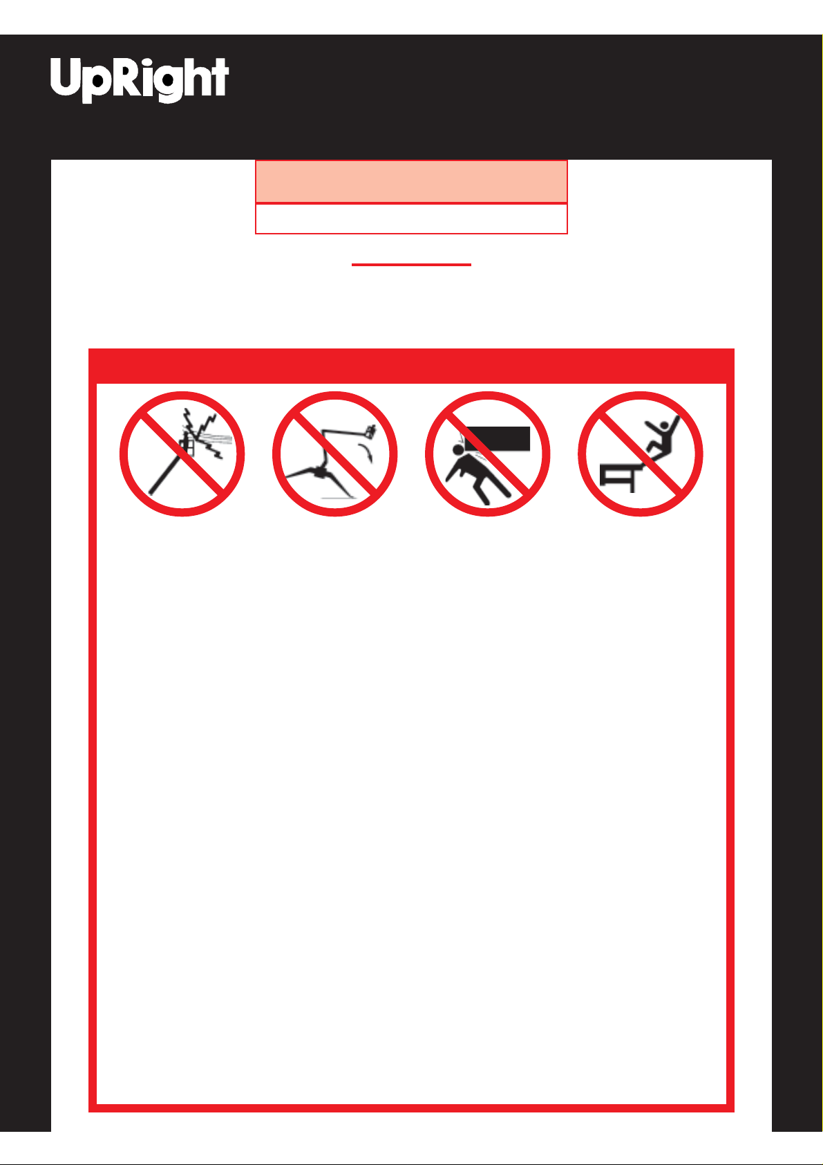
SAFETY RULES
NEVER operate this
machine within 10 feet of
power lines or cables.
THIS MACHINE IS NOT
INSULA TED.
ALL occupants must wear an approved fall restraint properly attached to a designated platform anchorage point. Attach
only one fall restraint to each anchorage point.
NEVER operate the machine without first surveying the work area for surface hazards such as holes, drop-off’s (curbs),
bumps and debris.
NEVER exceed the safe working load of 475 lbs (215 kg), (max. 2 persons plus 120 lbs (55 kg) of equipment).
DO NOT increase wind loadings by fitting items such as sign boards, flags etc. to the cage or boom.
DISTRIBUTE all loads evenly on the platform. See the Specifications Table on Page 16 for the maximum platform load.
NEVER operate the machine unless you have been fully trained in its safe use, are medically fit and have read and fully
understood these instructions.
OPERATE the machine on firm level ground with a minimum bearing capacity of 11,500 lbs / ft
DO NOT use in winds exceeding 27 mph (12.5 m/s - Beaufort Force 6).
NEVER use ladders or scaffolding on the platform.
DO NOT attach overhanging loads, increase the size of the working platform, use the machine as a crane or for any
other application involving additional loads or forces.
NEVER change or modify operating or safety systems.
INSPECT the machine thoroughly for missing decals, cracked welds, loose hardware, hydraulic leaks, damaged cables,
loose wire connections or wheel bolts. NEVER use damaged equipment. (Contact UpRight Irl. Ltd. for instructions).
NEVER climb down an elevating assembly with the platform elevated.
NEVER use this machine unless the platform entrance drop bar is in position.
NEVER perform service on or in the elevating assembly while the platform is elevated without first blocking the
elevating assembly.
NEVER recharge batteries near sparks or open flame; Charging batteries emit highly explosive hydrogen gas.
SECURE the work platform against unauthorized use by turning Keyswitch off, and then remove key from the switch.
NEVER replace any component or part with anything other than original UpRight replacement parts without the
manufacturer’s consent.
All Outrigger Pads must be in contact with a firm surface and the Chassis levelled before elevating the Platform.
IF ALARM SOUNDS while the platform is elevated, STOP. Carefully retract the booms, using the emergency
functions and lower the platform without slewing. Move the machine to a firm, level surface.
NEVER elevate the
Platform until all four (4)
Outriggers have been
correctly deployed.
NEVER position the
platform without first
checking for overhead
obstructions or other
hazards.
1
NEVER sit, stand or
climb on guard rail or
midrail of the
platform.
2
(550 kN / m2).
Safety Rules and Operating Instructions
Page 2

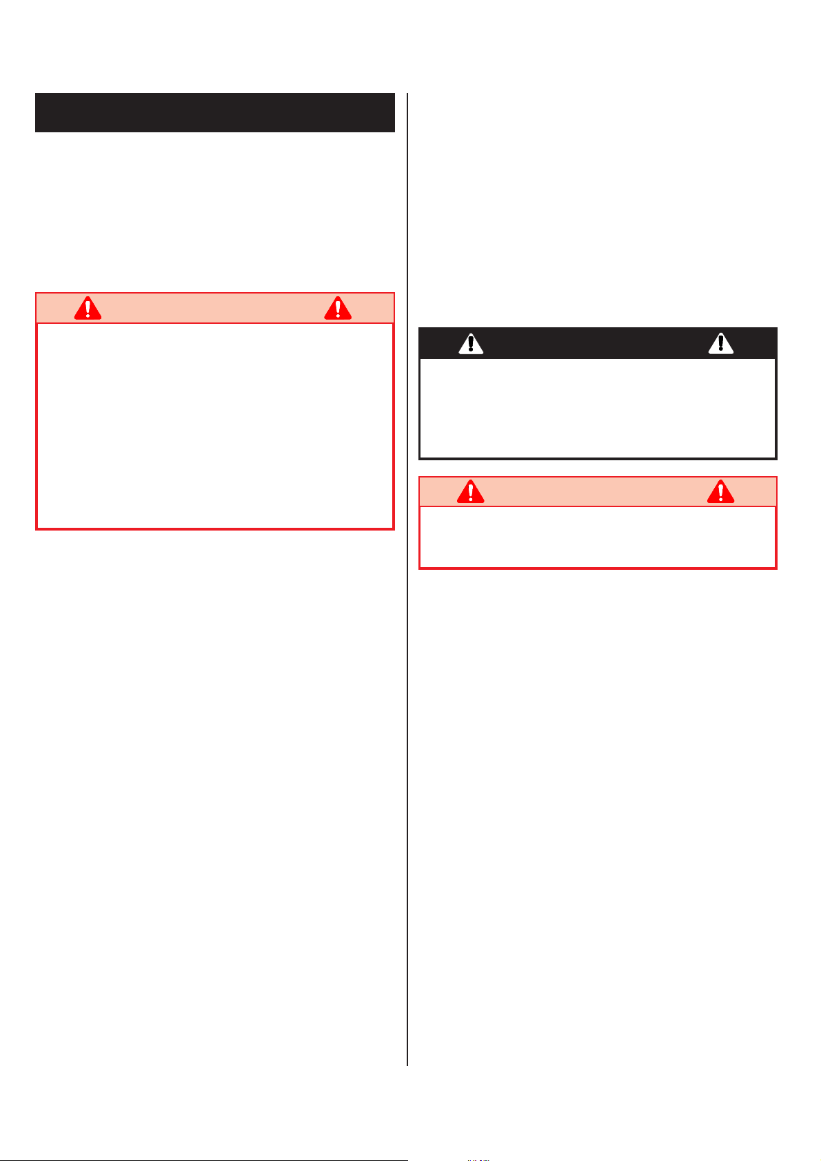
Introduction
This Manual covers the operation of the TL49 Trailer
Mounted Work Platform. This manual must be stored on
the machine at all times.
Pre-Operation & Safety
Inspection
WARNING
Carefully read, understand and follow all safety
rules and operating instructions. Perform the
following steps each day before use. DO NOT
perform service on the W ork Platform with the
platform elevated unless the elevating assembly is
properly supported.
1. Remove module covers and inspect for damage, oil
leaks or missing parts.
2. Check the level of the hydraulic oil with the platform
fully lowered and the Outriggers fully stowed. Oil
should be visible on the filler cap dip stick. If
necessary top-up using ISO#46 hydraulic oil.
3. Check that the electrolyte level in the batteries
is correct. (Battery Maintenance, Page 9)
4. Verify batteries are charged.
5. Check that the A.C. extension cord has been
disconnected from the charger.
6. Carefully inspect the entire machine for damage
such as cracked welds or structural members, loose
or missing parts, oil leaks, damaged cables or hoses,
loose connections and tyre damage.
7. Move machine, if necessary, to an unobstructed area
where machine can be fully elevated.
8. Check that the surface is capable of supporting
the outrigger loads, and is generally level. Apply the
handbrake.
9. Ensure that no leaks are present on the hydraulic
hoses to the Outrigger cylinders and that they are
properly secured. Check that there is no physical
damage to the cylinder body or ram. IF THERE IS
ANY DAMAGE DO NOT PROCEED IN
USING THE MACHINE.
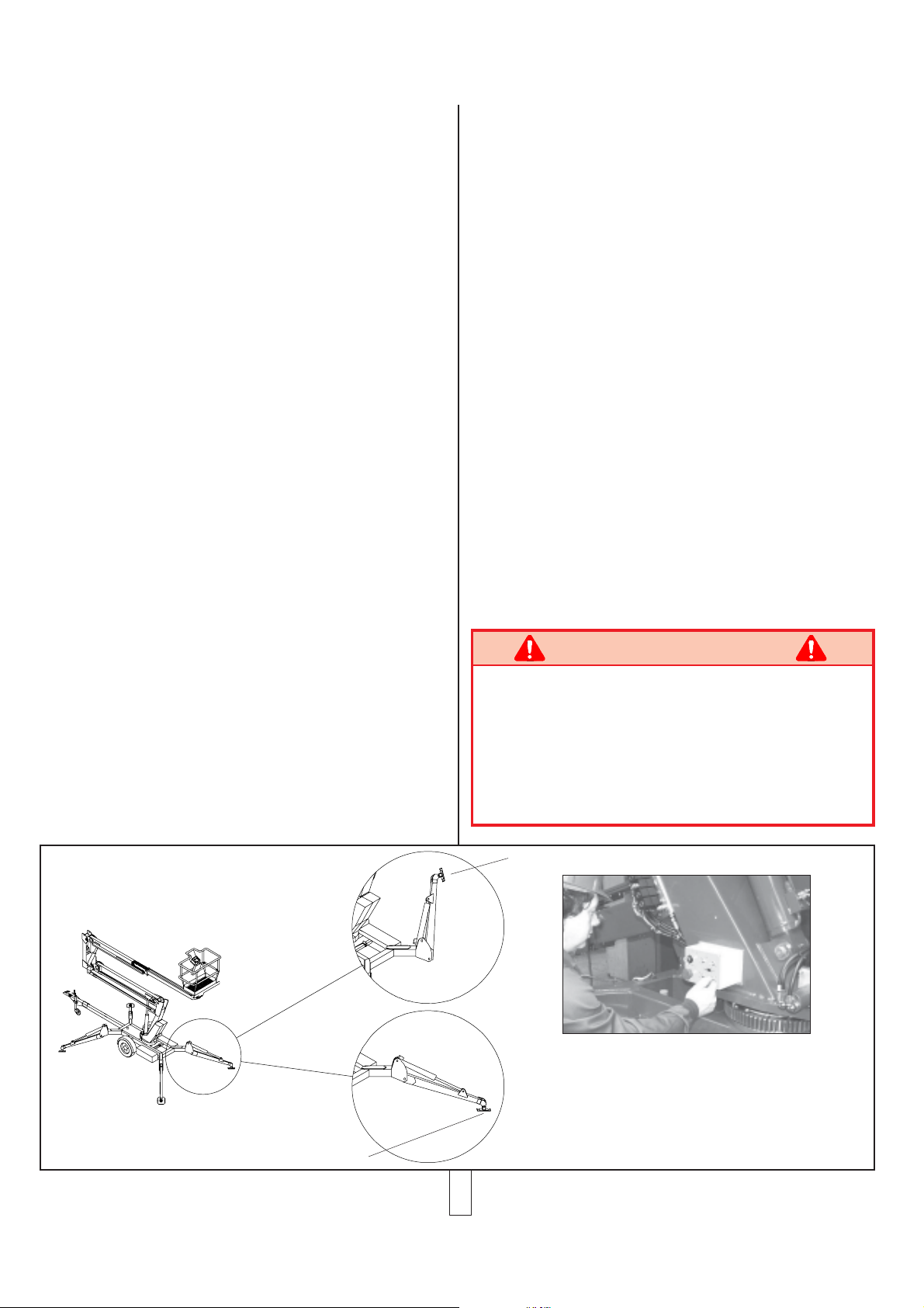
10. To extend the Hydraulic Outriggers an Operator
must first ensure that all Emergency Stop Buttons
are released (turned clockwise). Then turn the
Keyswitch to the chassis position and deploy the
Outriggers using the T oggle Switches until the
Outrigger Foot Pads come into contact with the
surface (See Figure 1). Care should be exercised
that the Foot Pads are orientated correctly. When all
four Outriggers are in contact with the surface the
Chassis can then be elevated. This should be done
by extending each Outrigger one at a time in small
increments until both of the Road Wheels have just
cleared the ground.
1 1 . The Chassis must then be levelled using the
Bubble Level on the rear of the Chassis as a
reference. When carrying out these minor
adjustments the last operation on the Outriggers
must be an extension so as to avoid the possibility of
minor settling in the Hydraulic Fluid.
For a more detailed description of this procedure the
instructions in the Operation Section of this
Operators Manual should be followed.
WARNING
Do not use a machine that is damaged or
malfunctioning. T ag and remove the unit from
service until it is repaired.
SYSTEM FUNCTION INSPECTION
NOTE:
Refer to Figure 2, Figure 3 & Figure 4 for the
Outrigger Control, Lower Control and Platform
Control locations.
WARNING
ST AND CLEAR of the W ork Platform while
performing the following checks.
BEFORE operating the W ork Platform survey the
work area for surface hazards such as holes, dropoff’s (curbs), bumps and debris.
CHECK in all directions, including above the
W ork Platform, for obstructions and power lines or
cables.
CORDON off the area within the platform’ s
working area to keep passers-by clear of the
booms.
12. Turn both of the Chassis and the Platform
Emergency Stop buttons ON (rotate clockwise).
Turn the Keyswitch on the Outrigger Control box to
the position marked CHASSIS (anticlockwise
position).
2
Page 3
13. Using the chassis control T oggle Switches, fully
ELEVATE Booms 1 & 2 and EXTEND the
T elescopic Boom.
14. V isually inspect the elevating assembly and cage
mounting/structure, lift cylinders, cables and hoses
for leaks, damage or erratic operation. Check for
missing or loose parts such as nuts, bolts and
circlips.
15. Test the Emergency Lowering Valves on the Upper
and Lower Lift Cylinder are operating correctly as
detailed on Page 6. PUSH/TURN the Emergency
Stop Button to identify that functions will indeed
cease when depressed.
16. Check the SLEW left and right function.
17. Return the machine to an elevated position just
above the Boom Rest 1 ft (300 mm). To confirm
that the Outriggers and Outrigger Limit Switches
will operate correctly while the machine is elevated,
it is then vital that each Outrigger Limit Switch is
individually tested.
Retract the Rear Left Outrigger using the Toggle
Switches on the Outrigger Control Box (will simulate
an Outrigger out of deployment). At this point the
TL49 should have the following characteristics;
the alarm will sound and the DOWN, RETRACT &
SLEW Boom functions only will be operable from the
Lower Controls.
The above test should be repeated for all Outriggers.
18. Lower each boom until the Elevating Assembly is
fully stowed. Repeat all the above tests from
the Platform Controls.
19. While testing the Platform Controls it is also
necessary to test that the Emergency Override
functions will work. While elevated in the Platform
request a colleague to activate the Tilt Sensor. The
alarm should sound and normal controls should
cease. By turning the Platform Selector Switch to
the Emergency Override position the DOWN
functions, RETRACT functions and SLEW
functions only will be activated.
The Emergency Override functions should also give
the Down & Slew functions only when an
Outrigger Limit Switch is deactivated. Carry out
the tests as outlined in Item No.17 in this section.
The System Function Inspection is then complete.
PRE-TRANSPORT INSPECTION
20. Lower the jockey wheel until it is in contact with the
surface.
21. Retract the Outriggers fully. To do this the operator
must use the Toggle Switches on the Outrigger
Control Box to raise each Outrigger individually in
small increments until the road wheels are taking the
W ork Platform’s weight. Raise the Outriggers until
they are locked in the required vertical position. The
Outriggers are now correctly stowed.
22. Return the Keyswitch to the OFF (centre) position.
Check tyre pressures and thread depth. These
procedures are further detailed on Page 8.
WARNING
If there are any concerns about the safe use or
operation of the TL49 following this
Pre-Operation Inspection DO NOT USE THE
TL49 WORK PLA TFORM. Contact your
supplier or UpRight’ s Product Support
Department.
Outrigger Raised
To activate the Outrigger Control Box the Keyswitch
must be turned to the CHASSIS position. For each
Outrigger there will be a toggle switch. Each toggle
switch will have its corresponding graphic.
To deploy (lower) an Outrigger it’s toggle switch
should be held down. To retract (raise) an
Outrigger Lowered
Outrigger it’s toggle switch should be held up.
Figure 1: Deploying the Outriggers
3
Page 4
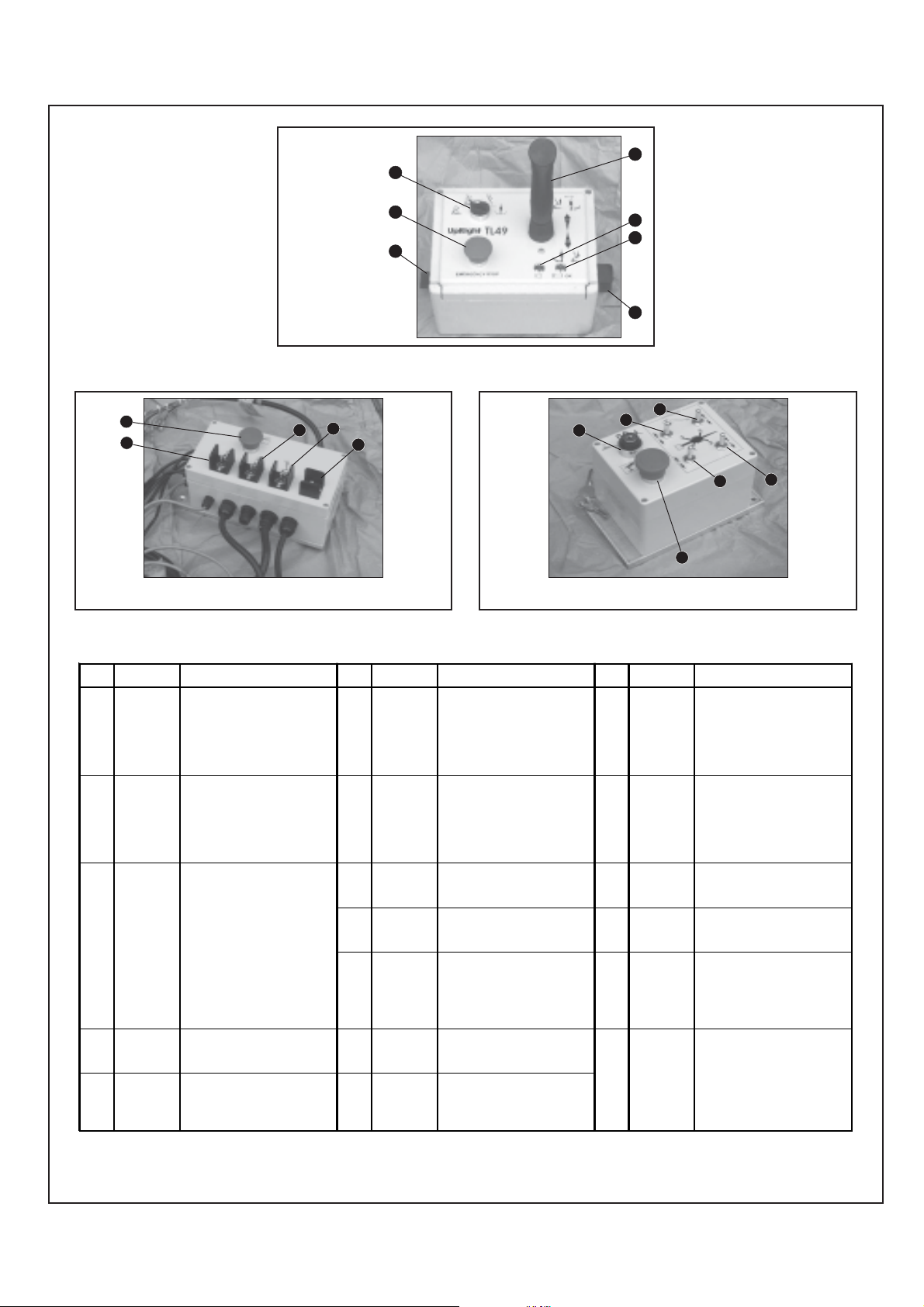
The On/Off/
Emergency
Override Switch
2
3
is located on the
left side of the
Upper Control
Box.
To utilize the
Emergency
4
1
6
5
Override feature
turn and hold
the Switch to the
‘EMERGENCY’
7
position.
Figure 2 : Upper Control Box
17
8
9
11
10
12
15
13
To operate the Toggle Switches above the Keyswitch (13)
must be turned to the anticlockwise position - CHASSIS.
Figure 3 : Lower Control Box
INDEX
NAME FUNCTION INDEX
NO.
1SWITCH :
ON/OFF/
EMERGENCY
OVERRIDE
2SELECTOR
SWITCH
3JOYSTICK
CONTROL
LEVER
4EMERGENCY
STOP
SWITCH
5SYSTEM OK
INDI CATOR
Turn clockwise for power 'ON', in
centre position for power 'OFF' and
anticlockwise for 'EME RGENC Y
OVERRIDE'. (Must be held against
spring pressure in this position)
Select function to be operated. Left
Hand position for BOOM1, the next
position for BOOM2 and the next
position for TELESCOPE. The SLEW
function is the Right Hand position.
Only one function can be sele c ted at
any one time.
Squeeze the Interlock Switch,
coloured red. This wi ll activate the
controller. To activate the BOOM1 UP,
BOOM2 UP, TELESCOPE
RE TR ACT o r ROTATE RIG H T
functions the controller s hould be
pushed forward.
To activate the BOOM1 DOWN,
BOOM2 DOWN, TELESCOPE
EXTEND or ROTATE L EFT f unctions
the controller should be
pulled back. The speed that each
function operates is related to how far
the Joystick is moved from the centre
position.
Push red button to cut off power to all
functions (OFF). Turn clockwise to
release and restore power.
Illuminates to indica te that the
Outrigger Switches are activated, i.e.
the Outriggers have been properly
deployed and that power is now
available to the Upper Control Box.
NAME FUNCTION INDEX
NO.
6BATTERY
CONDITION
INDICATOR
7 LEVEL
SWITCH
8EMERGENCY
STOP
SWITCH
9 BOOM 1
TOGGLE
SWITCH
10 BOOM 2
TOGGLE
SWITCH
11 TELESCOPE
TOGGLE
SWITCH
12 SLEW
TOGGLE
SWITCH
To operate the Toggle Switches above the Keyswitch (13)
must be turned to the anticlockwise position - CHASSIS.
Figure 4 : Ourtrigger Control Box
This red L.E.D. (Light Emitting Diode)
indicates the condition of the
batteries. It is constantly illumi nated
when the batteries are more than
80% discharged. It flashes repeatedly
when the batteries are 70%
discharged. It is not illuminated when
the batteries are fully charged.
This toggle switch allows the Platform
to have its 'level' adjusted either
forwards or backwards. To activate
this swi tch the P latfo r m must be
stowed and the ON/OFF/
EMERGENCY OVERRIDE Switch
must be held to the Emergency
Override Position.
Push red button to cut off power to all
functions (OFF). Turn clockwise to
release and restore power.
Boom1 can be raised by holding
toggle switch UP, and it can be
lowered by holding toggle switch
DOWN.
Boom2 can be rai sed by holding
toggle switch UP, and it can be
lowered by holding toggle switch
DOWN.
The Telescopic Boom can be
extended by holding toggle switch UP,
and it can be retracted by holding
toggle switch DOWN.
The elevating assembly can be
slewed LEFT by holding toggle switch
LEFT, and
RIGHT by holding switch RIGHT.
16
14
NAME FUNCTION
NO.
13 KEYSWITCH Turn the Key anticlockwise to select
14 EMERGENCY
STOP
SWITCH
15 OUTRIGGER
TOGGLE
SWITCH
Rear Left
16 OUTRIGGER
TOGGLE
SWITCH
Rear Right
17 OUTRIGGER
TOGGLE
SWITCH
Front Le ft
18 OUTRIGGER
TOGGLE
SWITCH
Front Right
the CHASSIS controls or clockwise to
select the PLATFORM controls.
Power OFF is in the centre position.
Push red button to cut off power to all
functions (OFF). Turn clockwise to
release and restore power.
The Outrigger assembly can be
extended by holding toggle switch
DOWN, and retracted by holding
switch UP.
The Outrigger assembly can be
extended by holding toggle switch
DOWN, and retracted by holding
switch UP.
The Outrigger assembly can be
extended by holding toggle switch
DOWN, and retracted by holding
switch UP.
The Outrigger assembly can be
extended by holding toggle switch
DOWN, and retracted by holding
switch UP.
18
NOTES :
* An alarm is located in the Upper Control Box. This will sound when Tilt Sensor is activated, and while this alarm is on only
the Emergency Override controls can be used. This alarm will also sound when an Outrigger Limit Switch opens.
4
Page 5
Operation
DEPLOYING THE OUTRIGGERS
Before operating the TL49 W ork Platform it is
imperative that the Pre-Operation Inspection has
been completed and any deficiencies have been
corrected. The operator must also be fully trained
on this machine.
TOWING
WARNING
Before T owing, ensure that the Elevating Assembly
is properly stowed and secured using the Locking
Pin, and that the Outriggers are raised, retracted
and locked into position. See Pre-Transport
Inspection on as before. Ensure the tyres are free
from damage, inflated to the correct pressure and
have sufficient thread depth. Ensure the breakaway
cable is properly attached to the towing vehicle
before driving away .
Adjust the Jockey Wheel using the screw handle until
the Towhitch is just above the height of the tow ball on
the towing vehicle.
Position the tow vehicle and fit the breakaway cable to
a suitable attachment point on the towing vehicle (not
the tow ball stem or towing pin).
While pushing the release button on the Towhitch lower
the Receiver onto the Tow Bar using the screw handle
on the Jockey Wheel, until the catch snaps into position.
Then when the receiver is secure and the Tow Bar is
taking some of the machines weight retract the Jockey
Wheel to its full extent, at which point the Jockey
Wheel will be in its locked position. Retighten the
clamp. This will negate the possibility of the wheel
moving and so the possibility of the Jockey Wheel
screwing down during transport.
Connect the electrical lead to the tow vehicles socket.
Check all lights for correct operation before transporting
the machine.
Position the TL49 on a firm, level surface. Apply the
handbrake and then lower the Jockey Wheel until it comes
into contact with the surface and retighten the clamp. As
the Jockey Wheel is further lowered release the locking
mechanism on the Tow Hitch Receiver. When clear of the
tow bar move the towing vehicle a small distance away
from the TL49. Next ensure that the TL49 is switched to
the ON position using the Keyswitch on the Outrigger
Control Box and that the Emergency Stop Buttons are also
OFF (turned clockwise to release).
DANGER
It is important that all outriggers are correctly
deployed on a firm surface capable of withstanding
the loads imposed. The Chassis MUST be
correctly levelled before elevating the platform.
WARNING
DO NOT use the TL49 W ork Platform unless the
System OK LED (Outriggers Ready) is illuminated.
1. Before deploying the Hydraulic Outriggers it is
necessary that the area be cleared of any objects or
personnel that may infringe on the Outriggers
deployment radius.
2. Turn the Keyswitch located on the Outrigger Control
Box to the ‘Chassis’ position and deploy the
Outriggers using the T oggle Switches until the
Outrigger Foot Pads come into contact with the
surface. Care should be exercised that the Foot
Pads are orientated correctly.Reference Figure 1.
3. When all four Outriggers are in contact with the
surface the Chassis can then be elevated. This
should be done by extending each Outrigger one at a
time in small increments until both of the Road
Wheels have just cleared the surface.
4. Ensure that the machine is level in all planes using
the Bubble Level located at the rear of the Chassis.
NOTE:
Exercise caution during brake “Running In” period
(First 500 miles or 850 Km). When parking on
slopes fully tension the Hand Brake. When moving
the TL49 in reverse ensure that the Hand Brake
spring is fully compressed. Check that the TL49 is
moving in reverse. When not in use it is advisable to
chock wheels to prevent movement.
The last operation to be carried out before entering the
Platform should be to check each of the Outriggers
individually for their stability and that in each instance the
Outrigger Limit Switch is activated. When the Keyswitch
is in the ‘CHASSIS’ position and the Outriggers are
properly deployed there should be no warning alarm.
5
Page 6

DANGER
When carrying out final adjustments in the levelling
of the chassis it is important that the last operation
on each Outrigger be an extension. This is to avoid
creating a reduced hydraulic pressure within the
Outriggers and hence negate the possibility of
minor settling.
ELEVATING & LOWERING THE TL33
WORK PLATFORM
When the TL49 has been thoroughly inspected, and has
been set up in accordance with the correct Outrigger
Deployment procedures, the Elevating Assembly can then
be used.
WARNING
LOOK up and around for obstructions before
performing the lift function.
ENSURE that the Elevating Assembly is clear of
the Chassis before engaging the Slew operation.
DO NOT overload the platform
illuminated. If not, and/or an audible alarm sounds,
check that the Outriggers are correctly deployed and
that the machine is level. The boom functions, nor
the slew function will operate if this is not correct.
5. Select “Boom 1” on the Function Selector Switch.
Check for overhead obstructions and when satisfied
squeeze the red Interlock control on the Joystick.
Slowly move the Joystick forward to elevate
Boom 1. The further the joystick is moved, the
faster the boom will move. Pressure must be applied
to the Interlock at all times while operation is
required.
6. Select “Boom 2”, “Telescope” or “Rotate” as
required using the ‘Function Selector Switch’ and
operate as described above. For boom one or two
functions the controls will be forward for UP and
backward for DOWN. For telescope retract the
Controller Joystick should be moved forward and for
rotate Telescope extend move the Controller
Joystick backward. To rotate (Slew) RIGHT the
Controller Joystick should be moved forward and to
rotate (Slew) LEFT move the Controller Joystick
backward.
7. Before lowering, check beneath the Platform floor
for obstructions. Operate as described above,
moving the Joystick to lower the Booms.
LEVELLING
DO NOT operate within 10 feet (3 metres) of any
electrical power cables. THIS WORK
PLA TFORM IS NOT INSULA TED.
Cordon off the area within the platform’ s working
area to keep passers-by clear of the booms.
NOTE: Chassis controls are for service use only.
1. Enter the Platform through the entrance provided
and ensure that the Drop Bar is in position. Where
applicable lock the Entry Step in the raised position.
2. Before using the machine all local Safety
Regulations involving helmets and restraining
devices should be observed. Safety harness
lanyards, not exceeding 1 m in length, should be
attached to the anchor points on the Platform floor.
3. Ensure the ‘ON/OFF/OVERRIDE’ switch on
the Upper Control Box switch is turned to the ON
, the Keyswitch on the Outrigger Control Box is
turned to CHASSIS position and all Emergency
Stop Buttons are OFF (twisted clockwise).
4. Check the green “System OK” L.E.D. is
NOTE:
The Cage Levelling function will only work when the
Boom Rest Limit Switch has been activated i.e. when
the Booms are stowed.
The platform can be levelled from the Upper controls using
the levelling switch (See Figure 1). To activate this switch
the ‘ON/OFF/OVERRIDE’ switch, also located on the
Upper Control Box, must be held to the OVERRIDE
position.
This switch is for fine adjustment of the slave levelling
cylinder . Care should be taken when performing this
operation. The switch should be operated cautiously to
level the cage slowly. Activate the switch in a careful,
controlled manner .
EMERGENCY SITUATIONS &
EMERGENCY OVERRIDE
In any emergency situation, the first action to be taken
should be to hit the red “Emergency Stop” button. This will
give instant cutout of all functions. It will then be required
to twist the button clockwise to release before the machine
can be operated again.
6
Page 7

If the Audible warning alarm sounds, normal control
functions will cease to operate. This will be due to one of
the following problems ;
z deactivation of an Outrigger Limit Switch.
z the activation of the T ilt Sensor.
In this situation the procedure is to turn the Platform “ON/
OFF/OVERRIDE” Switch to the ‘EMERGENCY
OVERRIDE’ position, and hold it in this position while
using the boom controls as normal to descend in a
controlled manner to ground level. Do not begin to rotate
until close to the ground.
After leaving the Platform, check all Outriggers and adjust
to ensure each is correctly deployed. Note that during
emergency operation, controls will operate only at a
fixed, slow speed and will not allow the raising of the
Booms. The Booms can only be lowered.
Emergency Lowering
Before operating the Emergency
Lowering Valves the surrounding
area should first be cleared of any
potential obstructions. It is also
important that when the valve is
pushed/turned, it is initially done
slowly. This is so that sudden
movement will not occur in the
Elevating Assembly, leading to a
potentially unstable machine.
CA UTION
When operating this function, extreme care must be
taken to ensure that the person carrying out the task
does not become trapped by the Elevating
Assembly .
Should the machine become inoperable when elevated
request a person on the ground to lower the platform using
the emergency lowering valves.
These are red knobs (push or twist type) mounted at the
base of the 2 Main Hydraulic Lift Cylinders (See Figure 5
opposite). The decal located on the TL49’s Lift Cylinder’s
will identify the Emergency Lowering Valves as either a
‘PUSH’ type or a ‘TWIST’ type.
Operate the lower boom first by pushing (turning
anticlockwise) slowly until the boom starts to descend. The
speed of descent iscontrolled by the amount the valve is
pushed (turned anticlockwise) - ensure that the rate of
descent is kept slow and under control. Descent can be
halted at any time by removing pressure from the red knob
for the ‘PUSH’ type, or turning the ‘TWIST’ type
clockwise.
Repeat the operation if necessary for the upper boom
when the cylinder is in reach of the ground.
With both main booms lowered fully it should then be
possible to leave the Platform safely. A small step ladder
can be used if necessary.
Figure 5: Emergency Lowering
Gerabox Manual
Rotation Shaft
To rotate the Elevating Assembly first apply a 17 mm
(13 mm) socket wrench to the shaft and turn to rotate
the Elevating Assembly. When finished remove the
wrench.
Figure 6: Manual Rotation
MANUAL ROTATION
1. Retract the Telescopic Boom and lower Boom2
fully. Ensure also that Boom1 is lowered as far as
possible, but just clear of the T ow Bar Weldment,
and that the Emergency Stop Button is pressed to
prevent any accidental powered operation.
2. Apply a or 17 mm (or 13 mm if required) socket
wrench to the Gearbox Drive Shaft and turn to
rotate the Elevating Assembly. The Gearbox Drive
7
Page 8

Shaft for the 17 mm type gearbox is shown in
Figure 6.
3. Remove the wrench.
CONTROL FROM GROUND LEVEL
1. Chassis Boom Controls are fitted in the Control
Module of the TL49 Work Platform. These should
only be used when no operator is in the Platform
(for maintenance/service or inspection purposes), or
if the operator has become incapacitated.
2. It should be noted that in order to activate any of the
Lower Control Toggle Switches on the Lower
Control Box the Keyswitch, located on the Outrigger
Control Box, must be turned anticlockwise to the
CHASSIS position.
3. Use the appropriate toggle switch to raise or lower
Boom 1, Boom 2, Telescope or rotate as required.
AFTER USE EACH DAY
1. Ensure that the Platform is fully lowered.
2. Park the machine on a level surface, preferably
undercover, secure against vandals, children or
unauthorised operation. Apply the Hand Brake.
3. Turn the Keyswitch to OFF and remove the key to
prevent any unauthorised operation.
4. Recharge the batteries in accordance with the
instructions on Page 9.
The TL49 may be lifted by an overhead hoist/crane in the
following manner:
Four lifting straps capable of safely supporting the total
weight of the TL49 (4,189 lbs (1,900 Kg)), and at least 8
feet (2.5 m) long are required. This minimum length is
important to ensure the correct lifting angle. The straps
should be positioned as shown in Figure 7.
The four lifting straps (Positions 1, 2, 3 & 4) should be
positioned at the points indicated in Figure 7. Care must be
taken to ensure the straps do not interfere with any other
parts of the TL49.
The four straps should be routed between the Outrigger
Footpad’s and the Outrigger Weldment.
Minimum sling length
- 8 feet (2.5 m)
Straps to be through
Footpad as indicated
by the arrows
shown.
Outrigger
Footpad
Transportation
BY FORKLIFT
CAUTION
The TL49 is not designed to be forklifted, and does
not have provision on the Chassis to allow this
method of lifting. UpRight recommends the
procedure below for handling the machine.
BY CRANE
WARNING
See specifications (Page 16) for the weight of
the work platform and be certain that lifting
apparatus is of adequate capacity to lift the
platform.
Figure 7: Lifting the TL49
BY ROAD
CAUTION
It is important that before commencing transport
to ensure the vehicle used is capable of towing
4,189 lbs (1,900 Kg).
The TL49 is a road approved vehicle and therefore may be
transported behind a motor vehicle of suitable towing
capacity . It is recommended that the vehicle used should
have a tow bar where the top of the ball is at a height of
between 1.42 ft (435 mm) and 1.64 ft (500 mm) above
surface level. These dimensions are also indicated below in
Figure 8. This is for the following reasons;
z the bottom of the Platform may be in danger of
hitting the surface while driving if the tow hitch is
above the upper limit.
8
Page 9

z the towing vehicle will support too much weight if
the T owhitch is too low.
1.64 ft (500 mm)
1.42 ft (435 mm)
Figure 8: Allowable Tow Hitch Height
If the TL49 is to be transported by other means then it
must be securely tied down to the transporting unit at
several points.
Recommended securing points are the four outrigger
support members on the Chassis and the Tow Bar
W eldment. Further securing points should be used if the
terrain on which the unit is travelling is rough or uneven.
Care should be taken when using tie downs that sensitive
parts of the TL49 (i.e. hosing, cabling etc.) are not
affected.
ALWA YS ensure that the Hand Brake is fully applied, that
all the booms are FULLY stowed and that the Boom Lock
Down Pin is in place.
Care should always be taken while towing the TL49 on an
uneven or sloped surface. It is recommended that the set
of procedures that follow should be incorporated into a
normal working practice for towing the TL49 Work
Platform. The Procedures which should be followed when
transporting the TL49 are:
1. The Platform is to be fully lowered, retracted and
slewed in the correct position.
2. The Platform is to be securely stowed by inserting
the Boom Lock Down Pin in its place. This is
located at the bottom of the Second Post.
3. The Jockey Wheel that is fitted to the Towhitch is
to be extended until the Receiver is close to the
height of the vehicle’ s tow bar.
4. The Hand Brake is pulled to engage the brakes
(important if the machine is not on a level surface).
5. The Outriggers are to be fully retracted and secured
in position.
6. The key is turned to the off position.
7. Move the vehicle as close as possible to the
Receiver.
8. Lift the Towhitch on to the tow bar and make sure
the Receiver is properly secured.
9. Release the Hand Brake and retract the Jockey
Wheel.
Maintenance
BATTERY MAINTENANCE
Electrical energy for the motor is supplied by four 6 volt
batteries wired in series to give a 24 volts DC supply.
Proper care and maintenance of the batteries and motor
will ensure maximum performance from the work
platform.
WARNING
Hazard of explosive gas mixture. Keep
sparks, flames and smoking materials away from
batteries
Always wear safety glasses when working
with batteries.
Battery fluid is highly corrosive. Rinse away
any spilled fluid thoroughly with clean water.
BATTERY INSPECTION AND
CLEANING
CA UTION
It is important that the Jockey Wheel is retracted as
fully as possible so that the wheel will not slew (turn)
while being transported. Failure to do so could
result in damage to the Jockey Wheel.
10. The tailboard harness is connected to the vehicle’s
braking system by means of a 7 Pin Plug.
11. Attach the Breakaway Safety Cable to the towing
vehicle.
The TL49 may then be towed.
Check battery fluid level daily , especially if work platform
is being used in a warm, dry climate. If required, add
distilled water; use of tap water with a high mineral content
will shorten battery life.
CAUTION
If battery water level is not maintained, batteries will
not fully charge, creating a low discharge rate which
will damage Motor/Pump unit and void warranty .
9
Page 10

Batteries should be inspected periodically for signs of
cracks in the cases, electrolyte leakage and
corrosion of the terminals. Inspect cables for worn spots or
breaks in the insulation and for broken cable terminals.
Clean batteries that show signs of corrosion at the
terminals or onto which electrolyte has overflowed during
charging. Use a baking soda solution to clean the batteries,
taking care not to get the solution inside the cells. Rinse
thoroughly with clean, warm water. Clean battery and
cable contact surfaces to a bright metal finish whenever a
cable is removed.
Basic Rule for maximum duty cycle of deep cycle
traction batteries:
z Use the machine until it shows signs of weak / slow
performance.
z Allow the charger to charge the batteries until it
automatically shuts off.
z A void intermittent charging as the batteries develop
a memory effect similar to Nicad batteries.
BATTERY CHARGING
Batteries do not have their full potential until they have
been through 50 charge/discharge cycles (however the
rate at which the potential increases is exponential, and the
batteries will normally have 95% potential after 15 charge/
discharge cycles). Hence do not use a new battery in a
battery pack that already has more than 15 cycles. Charge
batteries at the end of each work shift or sooner if
batteries have been discharged. A battery is considered to
have a faulty cell if it has less than 80% of the potential of
the other batteries in the pack while measured under load.
WARNING
Charge batteries in a well-ventilated area.
Do not charge batteries in the vicinity of sparks or
flames.
Permanent damage to batteries will result if they are
not immediately recharged after discharging.
Never leave charger operating unattended for more
than two days. Keep charger dry .
Never disconnect cables from batteries when
charger is operating.
To ensure a proper charge several items must first be
checked.
1. Correct voltage and current available to the charger.
2. Extension cord is in good condition, is no longer than
26 ft. (8 m) and is 12 ga (1.5 mm
3. Charger will have an adequate time to allow a full
charge i.e. ensure that power supply will not be
switched off overnight.
4. A.C. Voltage Selector Switch (110/220V) is in the
correct position.
All UpRight battery operated W ork Platforms, including the
TL49, are suitable for use in freezing and low temperature
conditions (to a value of -4ºF (-20ºC)). However for this
there are two provisions which must be met.
2
) or larger.
z The ISO#46 grade of hydraulic oil normally used in
UpRight Work Platforms must be replaced with a
grade suitable for these low temperature conditions.
z When ambient temperatures fall below 65ºF (18ºC)
batteries cannot deliver 220 Ampere hours and so
should be placed on charge as soon after use as
possible. Under such conditions a 4 hour equalize
charge once a week in the early afternoon will
improve state of charge and battery life.
Charging
1. Check battery fluid level. If electrolyte level is
lower than 3/8 in (10 mm) above plates add
distilled water only. (DO NOT OVERFILL)
2. Connect battery charger lead to properly
earthed outlet of correct voltage and frequency.
3. The Charger will turn on automatically after a
short delay . The LED’s will indicate the rate
of charging.
4. Charger turns off automatically when batteries
are fully charged.
HYDRAULIC OIL
With the Platform fully lowered i.e. stowed, oil should be
visible on the dipstick. If oil is NOT visible, fill the tank
until oil is then visible on the dipstick. DO NOT fill above
the upper line on the dipstick or when the platform is
elevated.
LUBRICATION
Refer to the Service & Parts Manual for the lubrication
chart and guidelines.
DECALS
Refer to Figure 9 on Pages 12 & 13 for the locations of the
Decals used on the TL49 Work Platform. These Decals
must be present and in good condition before operating the
Work Platform. Be sure to read, understand and follow
these Decals when operating the Work Platform.
10
Page 11

ROUTINE SERVICE
COMPONENT INSPECTION OR SERVICES INTERVAL Y N R
Use the following table as a guide for routine maintenance.
Inspection and maintenance shall be performed by
personnel who are trained and familiar with
mechanical and electrical procedures. Refer to the
Service & Parts Manual for complete service instructions.
Interval
Daily = each shift or every day
50h/30d = every 50 hours or 30 days
Y=Yes/Acceptable
N=No/Not Acceptable
R=Repaired/Acceptable
Preventative Maintenance Report
Date :________________________________
Owner : ______________________________
Model No : ____________________________
Serial No :____________________________
Serviced By :__________________________
Service Interval :________________________
Signature of Service Engineer
_____________________________
COMPONENT INSPECTION OR SERVICES INTERVAL Y N R
Battery Check electrolyte level Daily
System Check battery cable condition. Daily
Charge batteries. Daily
Check specific gravity. 50h/30d
Hydraul. Oil Check oil level. Daily
Hydraulic Wipe clean. 50h/30d
Pump Check for hose fitting leaks 50h/30d
Check for leaks at mating surfaces. 50h/30d
Check mounting bolts for proper 50h/30d
torque.
Hydraulic Check for leaks. Daily
System Check hose connections. 50h/30d
Check for exterior wear. 50h/30d
Emer. Open the emergency lowering Daily
Hydraulic valves and check for proper
System operation.
Control Check switch operation. Daily
Cable Check the exterior of cable for Daily
pinching, binding or cable wear.
Tyres / Check tyre press. 65 psi (4.5 bar) Daily
Wheels Check for damage. Daily
Check thread depth. Daily
Check/torque nuts 74 ft lbs-100 Nm Daily
Platform Check welds for cracks. Daily
Deck and Check condition of floor. Daily
Guardrails Check that securing bolts are Daily
tightened.
Check drop bar on cage entrance. Daily
Slew Grease slew gear. 50h/30d
System Check slew motor for leaks and 50h/30d
mounting bolts for proper torque.
Slew Check torque on all bolts, 15 outer 50h/30d
System/ ring and 20 inner ring.
First Post Retorque to 88 ft lbs (120 Nm).
Elevating Inspect for structural cracks. Daily
Assembly Check hoses for pinch or rubbing Daily
points.
Check pivot pins for damage. 50h/30d
Check pivot pin retaining rings. 50h/30d
Lift Check cylinder rod for wear. 50h/30d
Cylinders Check pivot pin retaining rings. 50h/30d
Grease all fittings as section 4.4. 50h/30d
Chassis Inspect for structural cracks. Daily
Assembly Check hoses for pinch or rubbing Daily
points.
Entire Unit Function check Emergency stop Daily
switches at control boxes.
Perform pre-operation inspection. Daily
Check for/repair collision damage. Daily
Lubricate. 50h/30d
Grease all fittings. 50h/30d
Outriggers Check outrigger cylinders for Daily
damage.
Check interlock switch function. Daily
Lubricate. 50h/30d
Grease all fittings. 50h/30d
Tow Hitch Check coupling for function and Daily
wear.
Inspect breakaway cable for Daily
proper attachment.
Grease all fittings as per the 50h/30d
Service & Parts Manual Section 4.4
Road Check all trailer lights and Daily
Lights connecting plug
Brake Apply handbrake and check Daily
function.
Check brake shoes for wear. 50h/30d
Test auto reverse function. 50h/30d
Adjust brake shoes. 50h/30d
11
Page 12

058186-000
1 REQUIRED
057418-000
4 REQUIRED
057385-000
8 REQUIRED
057429-000
2 REQUIRED
057430-000
2 REQUIRED
058534-000
2 REQUIRED
058011-000
1 REQUIRED
058010-000
1 REQUIRED
058761-000
058760-000
2 REQUIRED
1 REQUIRED
058535-000
2 REQUIRED
058536-000
1 REQUIRED
058750-000
2 REQUIRED
057382-000
2 REQUIRED
057433-000
2 REQUIRED
057427-000
2 REQUIRED
057424-000
3 REQUIRED
057416-000
2 REQUIRED
058533-000
2 REQUIRED
058539-000
1 REQUIRED
057428-000
1 REQUIRED
058532-000
1 REQUIRED
057507-010
2 REQUIRED
TL49 DECALS: THESE DECALS SHALL BE PRESENT AND IN GOOD CONDITION BEFORE
OPERATING THE WORK PLA TFORM. BE SURE T O READ, UNDERSTAND AND FOLLOW
THESE DECALS WHEN OPERATING THE WORK PLATFORM.
057421-000
2 REQUIRED
Figure 9: Decal Identification
12
Page 13

057420-000
1 REQUIRED
057425-001
1 REQUIRED
057426-000
1 REQUIRED
057387-000
1 REQUIRED
NOT SHOWN
MOS90 DECAL
058992-000
1 REQUIRED
NOT SHOWN
BOOM LOCK PIN
058012-000
1 REQUIRED
058080-000
1 REQUIRED
058538-000
1 REQUIRED
057424-000
3 REQUIRED
057435-000
1 REQUIRED
057434-000
1 REQUIRED
057432-000
2 REQUIRED
058760-000
2 REQUIRED
057422-000
2 REQUIRED
057431-001
1 REQUIRED
13
058802-000
1 REQUIRED
057417-010
4 REQUIRED
Note: Decals can be ordered by using the Part Numbers located beneath each decal.
This Operators Manual (Part Number 058651-000) is located in the Manual Holder within the Platform
Page 14

Notes:
14
Page 15

Notes:
15
Page 16

16
 Loading...