

Page 1

Engine Powered
Gasoline, Diesel,
Battery Electric,
Bi-Energy Options
OPERATORS
MANUAL
Part Number 13225A-EN
Serial Number 000001 and after JAN 2012 (REV D)
Page 2

Page 3

Page 4

LIMITED WARRANTY
Snorkel warrants each new machine manufactured and sold by it to be free from defects in material and workmanship
for a period of one (1) year from date of delivery to a Customer or for one year after the machine has been placed in
rst service in a Dealer rental eet, whichever comes rst. Any part or parts which, upon examination by the Snorkel
Service Department, are found to be defective, will be replaced or repaired, at the sole discretion of Snorkel, through
its local Authorized Dealer at no charge.
Snorkel further warrants the structural components; specically, the mainframe chassis, turntable, booms and scissor
arms, of each new machine manufactured by it to be free from defects in material and workmanship for an additional
period of four (4) years. Any such part or parts which, upon examination by the Snorkel Service Department, are found
to be defective will be replaced or repaired by Snorkel through its local Authorized Dealer at no charge; however, any
labor charges incurred as a result of such replacement or repair will be the responsibility of the Customer or Dealer.
The Snorkel Service Department must be notied within forty-eight (48) hours of any possible warranty situation
during the applicable warranty period. Personnel performing warranty repair or replacement must obtain specic
approval by Snorkel Service Department prior to performing any warranty repair or replacement.
Customer and Dealer shall not be entitled to the benets of this warranty and Snorkel shall have no obligations
hereunder unless the “Pre-Delivery and Inspection Report” has been properly completed and returned to the Snorkel
Service Department within ten (10) days after delivery of the Snorkel product to Customer or Dealer’s rental eet.
Snorkel must be notied, in writing, within ten (10) days, of any machine sold to a Customer from a Dealer’s rental
eet during the warranty period.
At the direction of the Snorkel Service Department, any component part(s) of Snorkel products to be replaced
or repaired under this warranty program must be returned freight prepaid to the Snorkel Service Department for
inspection. All warranty replacement parts will be shipped freight prepaid (standard ground) from the Snorkel Service
Department or from Snorkel’s Vendor to Dealer or Customer.
REPLACEMENT PARTS WARRANTY
Any replacement or service part made or sold by Snorkel is not subject to the preceding Limited Warranty beyond
the normal warranty period of the machine upon which the part was installed.
THIS WARRANTY EXCLUDES AND SNORKEL DOES NOT WARRANT:
1. Engines, motors, tires and batteries which are manufactured by suppliers to Snorkel, who furnish their own warranty.
Snorkel will, however, to the extent permitted, pass through any such warranty protection to the Customer or
Dealer.
2. Any Snorkel product which has been modied or altered outside Snorkel’s factory without Snorkel’s written approval,
if such modication or alteration, in the sole judgment of Snorkel’s Engineering and/or Service Departments,
adversely affects the stability, reliability or service life of the Snorkel product or any component thereof.
3. Any Snorkel product which has been subject to misuse, improper maintenance or accident. “Misuse” includes but
is not limited to operation beyond the factory-rated load capacity and speeds. “Improper maintenance” includes
but is not limited to failure to follow the recommendations contained in the Snorkel Operation, Maintenance,
Repair Parts Manuals. Snorkel is not responsible for normal maintenance, service adjustments and replacements,
including but not limited to hydraulic uid, lters and lubrication.
4. Normal wear of any Snorkel component part(s). Normal wear of component parts may vary with the type application
or type of environment in which the machine may be used; such as, but not limited to sandblasting applications.
5. Any Snorkel product that has come in direct contact with any chemical or abrasive material.
6. Incidental or consequential expenses, losses, or damages related to any part or equipment failure, including
but not limited to freight cost to transport the machine to a repair facility, downtime of the machine, lost time for
workers, lost orders, lost rental revenue, lost prots or increased cost.
This warranty is expressly in lieu of all other warranties, representations or liabilities of Snorkel, either expressed or
implied, unless otherwise amended in writing by Snorkel’s President, Vice President-Engineering, Vice PresidentSales or Vice President-Marketing.
SNORKEL MAKES NO WARRANTIES WHICH EXTEND BEYOND THE DESCRIPTION OF THIS
LIMITED WARRANTY. SNORKEL MAKES NO IMPLIED WARRANTY OF MERCHANTABILITY
OR FITNESS FOR A PARTICULAR PURPOSE AND DISCLAIMS ALL LIABILITY FOR
INCIDENTAL OR CONSEQUENTIAL DAMAGES, INCLUDING BUT NOT LIMITED TO INJURY
TO PERSONS OR PROPERTY.
The Customer shall make all warranty claims through its local Authorized Dealer and should contact the Dealer from
whom the Snorkel product was purchased for warranty service. Or, if unable to contact the Dealer, contact the Snorkel
Service Department for further assistance.
Effective July 1995
Page 5

Electrical Hazard
■ Electrical Hazard Warning
DANGER
THE TL39T AERIAL WORK PLATFORM, IN STANDARD CONFIGURATION, IS
NOT ELECTRICALLY INSULATED.
If the plat form, booms, or any other conductive part of a TL39T contacts a high-voltage electrical
conductor, the result can be SERIOUS INJURY or DEATH for persons on or near the machine.
GO NO CLOSER THAN THE MINIMUM SAFE APPROACH
DISTANCES (M.S.A.D) - AS OUTLINED IN TABLE 1. AND FIGURE 3.,
ON THE NEXT PAGE.
Be sure to allow for sag and sway in the wires and the work platform.
If a TL39T comes in contact with a live electrical conductor, the entire machine can be charged.
If that happens, you should re main on the machine and not contact any other structure or object within
reach. That includes the ground, adjacent buildings, poles, and any object not a part of the TL39T.
Such contact could make your body a conductor to the other object creating an electrical shock hazard
resulting in SERIOUS INJURY or DEATH.
DO NOT attempt to enter or leave the TL39T until you are sure the electricity has been turned off.
If a TL39T is in contact with a live conductor, the platform operator MUST warn others on the ground
in the vicinity of the TL39T to STAY AWAY from the machine, since their bodies can also form a path
for electricity to ground thus creating an electrical shock hazard with possible ELECTROCUTION and
DEATH.
DO NOT attempt to operate the TL39T ground controls when the platform, booms, or any other conducting
part of a TL39T is in contact with electrical wires or if there is an immediate danger of such contact.
Regard all conductors as energized.
Personnel working on or near a TL39T must be continuously aware of electrical hazards, recognizing that
SERIOUS INJURY or DEATH can result if contact with an electrical wire does occur.
Rev C page - i
Page 6
Electrical Hazard
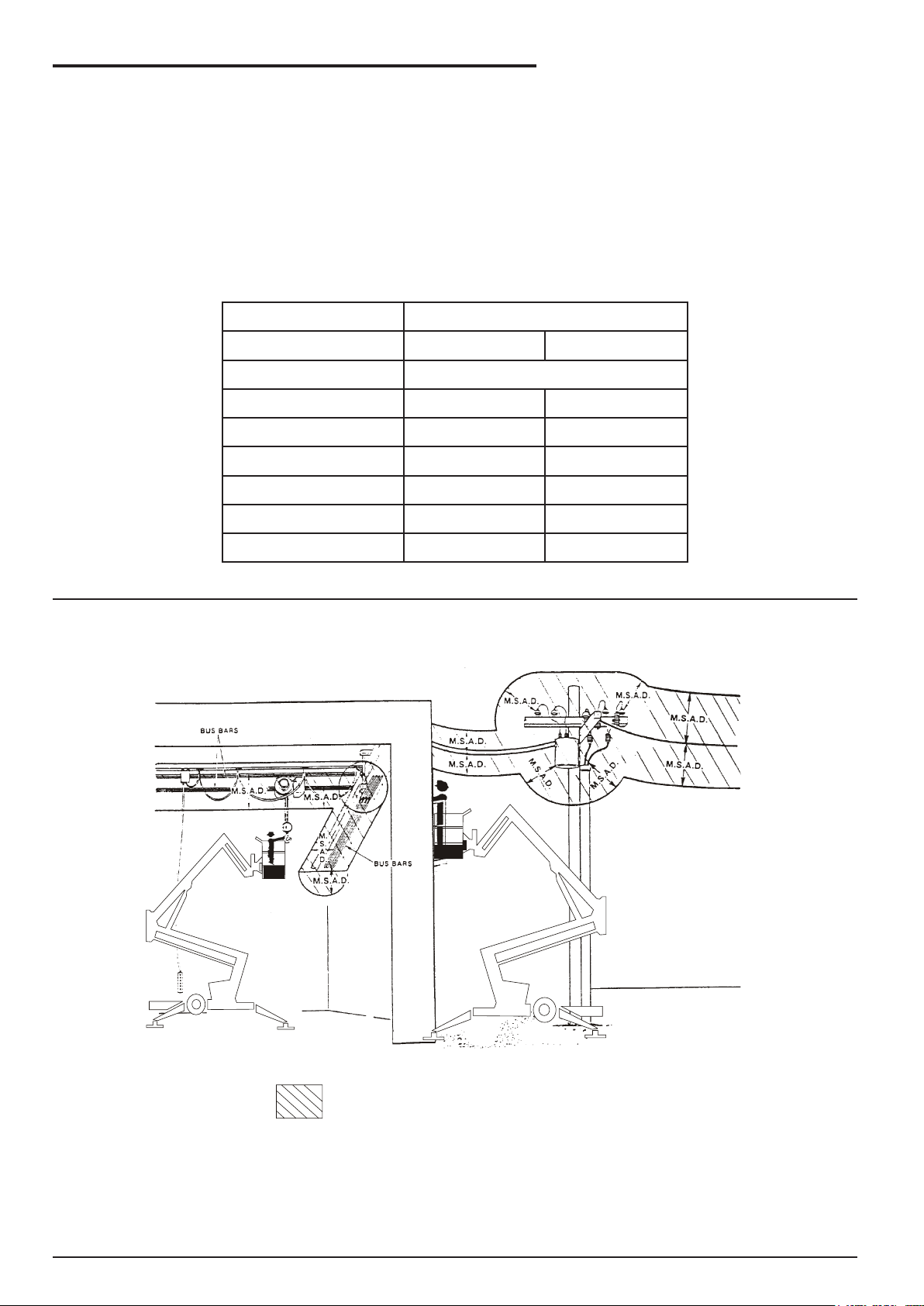
■ Minimum Safe Approach Distance
The TL39T is an all metal boom, NOT ELECTRICALLY INSULATED, aerial work platform. DO NOT
operate it near ELECTRICAL conductors. Regard all conductors as being energized. Use the table and
illustration below to determine safe clearance from electrical conductors. (Table 1 and Figure 3, below, are
from ANSI/SIA A92.5–1992 Standard, reprinted with permission of Scaffold Industry Association.)
□ Table 1 - (M.S.A.D.)
Minimum Safe Approach Distance to energized
(exposed or insulated power lines)
Voltage range Minimum safe approach distance
(phase to phase) (Feet) (Meters)
0 to 300V Avoid contact
over 300v to 50kv 10 3.05
over 50kv to 200kv 15 4.60
over 200kv to 350kv 20 6.10
over 350kv to 500kv 25 7.62
over 500kv to 750kv 35 10.67
over 750kv to 1000kv 45 13.72
Denotes prohibited zone
Danger: - Do not allow machine personnel or conductive
materials inside prohibited zone.
- Maintain M.S.A.D. From all energised lines and
parts as well as those shown.
- Assume all electrical parts and wires are energised
unless known otherwise.
Caution - Diagrams shown are only for purposes of illustrating
M.S.A.D. Work positions, not all work positions.
page - ii Rev C
Page 7

Introduction
The most important chapter in this manual is the
safety chapter - Chapter 1. Take time, now, to study
it closely.
The information in Chapter 1, might save your life,
prevent serious in jury, or damage to property or
the TL39T.
This introduction also contains important information
concerning the responsibilities of the owner of this
machine.
■ Standard TL39T
The standard TL39T in cludes the following
features:
● Independently operated heavy duty hydraulic
stabilizers
● Manual stabilisers
● 540° slew
● Heavy duty tow coupling
● Heavy duty jockey wheel
● Hour meter
● Hydraulic disc brakes
● Steel platform - 2 person capacity
● High strength steel boom and base
construction
● Beam axle with 15” rims
● Honda petrol engine
● 600V AC rated wire to platform
● Stabiliser/boom interlocks
● Stabiliser lift points
● Gravity gate
● Manual basket rotator
● LED taillights
● Height restrictor in upper cylinder to
keep platform at 10.9m maximum height
(TL39T only)
● 235 R15 x 75 tyres
■ Options
The following options are available for the TL39T:
● Automatic stabilisers
● Custom colours
● Platform work lights
● Air line to platform
● Flashing light
● Spare wheel
● 10.9m height lockout kit
● 240V110V outlet in platform
● Battery isolate switch
● Platform foot switch
● Alternative power options
❍ Diesel engined
❍ 24VDC power
❍ 240V power
❍ 110V power
● Bi-Energy options
❍ Petrol / 24V
❍ Petrol / 240V
❍ Diesel / 24V
❍ Diesel / 240V
❍ 24V / 240V
● Platform overload protection
■ Operation Manual
This manual provides information for safe and
proper operation of the aerial platform.
Read and understand the information in this
Operator’s manual before operating this machine
on a job site.
Additional copies of this manual may be ordered
from Snorkel. Supply the model and manual part
number from the front cover to assure that the
correct manual will be supplied.
All information in this manual is based on the latest
product information at the time of publication.
Snorkel reserves the right to make product changes
at any time without obligation.
■ Photographs
Photographs are taken to represent the machine
and its component parts as clearly as possible.
How ever, there may be minor differences between
the photographs and your machine. This represents
individual customer preferences and Snorkel’s
on-going commitment to product development.
■ Safety Alerts
A safety alert symbol is used through out this
manual to indicate danger, warning, caution, and
important instructions. Follow these instructions to
reduce the like li hood of personal injury, property
damage, or damage to the machine.
The terms danger, warning, and caution indicate
varying degrees of personal injury or property
damage that can result if the instruction is not
followed.
! DANGER
Denotes an imminently hazardous situation
which, if not avoided, will result in death or
serious injury.
Rev C page - iii
Page 8

Introduction
! WARNING
Denotes a potentially hazardous situation
which, if not avoided, could result in death or
serious injury.
! CAUTION
Denotes a potentially hazardous situation
which, if not avoided, may result in minor or
moderate injury.
It may also be used to alert against unsafe
practices or action which may result in
damage to the MHP.
! IMPORTANT
Denotes important information pertaining
to settings, capacities, or conditions, which
could, if ignored, lead to machine damage or
future hazardous situations.
It is also used to alert the reader to pay
careful attention to a particular passage of
text in the manual.
Notes
Notes are used to provide special information or
helpful hints to assist in aerial platform operation,
but do not indicate a hazardous situation.
■ Operation
The MHP ae rial platform has built-in safety features
and has been factory tested for compliance with
Snorkel specications and industry standards. How
ever, any personnel lifting device can be potentially
dangerous in the hands of untrained or careless
operators.
Training is vitally important and must be performed
under the direction of a QUALIFIED person. You
must display prociency in knowledge and actual
operation of the MHP before using it on a job site.
Before operation of the MHP you must read and
understand the operatingin structions in this manual
as well as the decals, warnings, and in structions
on the machine itself.
Before operating the MHP you must be
AUTHORIZED by the person in charge to do so and
the operation of the MHP must be within the scope
of the machine specications.
Read and understand the information in this
manual and on the placards and decals on the
machine before operating the MHP on the job.
■ Maintenance
Every person who maintains, inspects, tests,
or repairs these machines, and every person
supervising any of these functions, must be properly
trained and qualied to do so.
This Operators Manual provides a Pre-operational
Inspection procedure that will help you keep your
MHP in good operating condition.
Do not perform other maintenance unless you are
a trained mechanic, qualied to work on the MHP.
Call qualied maintenance personnel if you nd
problems or malfunctions.
Do not modify this machine without written approval
from the Engineering Department of Snorkel New
Zealand. Modication may void the warranty,
adversely affect stability, or affect the operational
characteristics of the MHP.
■ Responsibilities of Parties
! IMPORTANT
It is imperative that all owners and users of
the MHP read, understand, and conform to all
applicable regulations.
Ultimate compliance to OSHA regulations is the
responsibility of the user and their employer.
! IMPORTANT
ANSI Standard A92.6 clearly identies
requirements of all parties who might be
involved with Self-Propelled Elevating Work
Platforms.
AUSTRALIAN / NZ STANDARD 2550-10 Also
identies the requirements of all parties who
might be involved with Boom-Supported
Elevating Work Platforms.
NOTE - Standards
It is the responsibility of the owner to ensure that
the person operating the TL39T is provided with all
the relevant information relating to standards and
codes of practice applicable in their region.
! WARNING
The potential for an accident increases when
the aerial platform is operated by personnel
who are not trained and authorised. death or
serious injury can result from such accidents.
page - iv Rev C
Page 9

❑ In summary
● Only trained and authorised operators should
be permitted to operate the equipment.
● All manufacturers operating instructions,
and all safety rules, and all employers safety
rules, and all OSHA and other government or
local authority safety rules should be strictly
adhered to.
● Repairs and adjustments should be made
only by qualied and trained maintenance
personnel.
● No modication should be made to the
equipment without prior written consent of
the Engineering Department, Snorkel New
Zealand.
● Make a pre-start inspection of the MHP at
the beginning of each shift. A malfunctioning
machine must not be used.
● Make an inspection of the work place to locate
possible hazards before operating the MHP.
Introduction
■ Additional Information
For additional information, contact your local dealer
or Snorkel at:
Snorkel New Zealand,
PO Box 1041
Levin 5540
New Zealand
Rev C page - v
Page 10

Page 11

Table of Contents
Electrical Hazard
Electrical Hazard Warning ...................................... i
Minimum Safe Approach Distance ........................ ii
Table 1 - (M.S.A.D.) ............................................. ii
Introduction
Standard TL39T .................................................... iii
Options ................................................................. iii
Operation Manual ................................................. iii
Photographs ......................................................... iii
Safety Alerts ......................................................... iii
Operation .............................................................. iv
Maintenance ......................................................... iv
Responsibilities of Parties ....................................iv
In summary ..........................................................v
Additional Information ............................................ v
1. Safety
Safe Operation .................................................. 1-1
Electrocution Hazards ....................................... 1-1
Minimum safe approach distance .................... 1-1
Pre-start Inspection ........................................... 1-2
Work Place Inspection and Practices ................ 1-2
Operation ........................................................... 1-3
Tipover and Falling Hazards .............................. 1-3
General Safety Precautions ............................... 1-4
Hydraulic System Precautions ........................... 1-4
Fire Prevention .................................................. 1-4
Engine and Fuel Handling Precautions ............. 1-4
Batteries ............................................................ 1-4
Height Restriction .............................................. 1-5
Height Restriction on TL39T .............................. 1-5
10.9 Metre Restriction Kit .................................. 1-5
Safety Decals and Placards .............................. 1-5
2. Safety Devices
Safety Device Information ..................................2-1
Emergency Stop Switches ..................................2-1
At ground control box .......................................2-1
At platform control box ......................................2-1
Other Safety Devices ..........................................2-1
Lanyard anchor points ......................................2-1
Gravity gate ......................................................2-2
Guardrails .........................................................2-2
Height restriction on TL39T ..............................2-2
10.9m height restriction kit (Option) ................. 2-2
Enable switch .................................................. 2-2
Enable switch (foot) – Optional ........................ 2-3
Bubble level ..................................................... 2-3
RCD/ELCB AC outlet (Option) ......................... 2-3
Flashing light (Option) ......................................2-3
3. Specications
General Specications ........................................3-1
Specications MHP14AT ....................................3-1
Specications TL39T ..........................................3-2
Engine Data ........................................................ 3-3
Working Envelope - TL39T ................................. 3-4
Nomenclature ..................................................... 3-5
4. Gauges
Hourmeter ...........................................................4-1
Level Bubble ....................................................... 4-1
Hydraulic Oil Level ..............................................4-1
5. Shut-offs and Circuit Breakers
RCD/ELCB Outlet (option) ..................................5-1
Main Circuit Breaker ...........................................5-1
Stabilisers ...........................................................5-1
6. Controls
Controls Description ........................................... 6-1
Controls and Control Decal Locations ..............6-1
Ground Control Box ............................................ 6-2
Lower controls / indicators ................................6-2
Platform Control Box ..........................................6-3
Upper controls / indicators ................................6-3
Stabiliser Controls (Manual) ............................... 6-5
Self Levelling Stabilisers (Option) .......................6-6
7. Pre-operational Inspection
Pre-operational Inspection Table ........................7-1
Engine Fuel Level ............................................... 7-2
Fuel Tank Cap ....................................................7-2
Fuel Leaks ..........................................................7-2
Engine Oil Level .................................................7-2
Operator’s Manual ..............................................7-2
Wiring Harnesses ............................................... 7-2
Battery Terminals ................................................7-3
Battery Fluid Level .............................................. 7-3
Hydraulic Oil Level ..............................................7-3
Hydraulic Oil Leaks .............................................7-3
Bolts and Fasteners ............................................7-4
Wheels and Tyres ...............................................7-4
Tyre Pressure ...................................................7-4
Structural Damage and Welds ............................7-5
Lanyard Anchor Points ....................................... 7-5
Platform Gravity Gate .........................................7-5
Platform Guardrails .............................................7-5
Platform Access Ladder ......................................7-5
Flashing Light (option) ........................................7-6
Ground Control Switches ....................................7-6
Emergency Lower ...............................................7-6
Ground Station ...................................................7-6
Upper control box .............................................7-6
Platform Control Switches .................................. 7-7
Rev C page - vii
Page 12

Table of Contents
AC Outlet RCD/ELCB (option) ............................7-7
Placards and Decals ...........................................7-7
Placards and Decals ...........................................7-7
Standard placards and decals ..........................7-7
Decal list ...........................................................7-8
Decal inspection drawing .................................. 7-9
8. Operation
Operating Procedures ........................................8-1
Control Stations ..................................................8-1
Emergency Stopping .......................................... 8-1
Emergency Stopping .......................................... 8-1
Operation Considerations ................................... 8-1
Stabiliser Operation ............................................8-1
Using the manual stabiliser valves ...................8-2
Raising the manually operated stabilizers ........8-2
Self levelling stabilisers (Optional) ......................8-3
Setting the stabilisers manually ........................8-3
Unlocking the boom ............................................ 8-3
Starting From Ground Control Box .....................8-3
Starting From Platform Control Box ....................8-4
Moving The Platform ..........................................8-5
From ground control box ..................................8-5
From platform control box ................................. 8-5
Rotating the platform ........................................8-6
Securing for Day ............................................... 8-6
Bi-Energy, Petrol/Diesel / 240V AC .................. 11-3
AC motor ........................................................ 11-3
AC motor operation ........................................ 11-3
AC power connection ..................................... 11-4
Operation ........................................................ 11-4
Bi-Energy, Hydraulic Oil Tank ......................... 11-4
Other Options ................................................... 11-4
Air Line To Platform .......................................... 11-4
Work Lights ....................................................... 11-4
Flashing Light ................................................... 11-4
Battery Isolate Switch ....................................... 11-4
Alternative Power Options ................................ 11-4
RCD/ELCB AC Outlet ....................................... 11-4
Self Levelling Stabiliser ....................................11-5
Spare Wheel ..................................................... 11-5
Platform Foot Switch ........................................11-5
10.9 Metre Height Restriction Kit ...................... 11-5
Platform Overload Protection ...........................11-6
12. Fire Fighting and Chemical Control
Hazardous Components ................................... 12-1
Battery, Lead/Acid (UN 2794) .........................12-1
Gasoline (UN 1203) ........................................12-2
Hydraulic Oil (UN 1270) .................................. 12-3
Motor Oil (UN 1270) .......................................12-3
9. Emergency Operation
Emergency Operation Procedures ..................... 9-1
Emergency Operation Procedures ..................... 9-1
Operation from platform control box ...................9-1
Operation from ground control position .............. 9-2
10. Stowing and Transporting
Stowing ............................................................. 10-1
The correct stowed position is shown here ....10-1
Transporting .....................................................10-1
Trailering ......................................................... 10-1
Securing to a Transport Vehicle ......................10-1
Towing ..............................................................10-2
11. Options
Bi-Energy, Petrol/Diesel / 24V DC .................... 11-1
DC motor ........................................................ 11-1
DC motor operation ........................................ 11-1
DC motor battery switch ................................. 11-1
Setting the manual stabilizers ......................... 11-1
Setting the automatic stabilizers ..................... 11-1
Operation ........................................................ 11-2
Batteries ......................................................... 11-2
Battery charger ............................................... 11-2
Batteries - general maintenance ..................... 11-3
Batteries – charging ........................................ 11-3
13. Operator’s Troubleshooting
Troubleshooting ................................................ 13-1
Operator Troubleshooting Chart .....................13-1
Appendix A. Glossary
page - viii Rev C
Page 13
1. Safety
■ Safe Operation
Knowledge of the information in this manual, and
proper training, provide a basis for safely operating
the TL39T. Know the location of all the controls and
how they operate to act quickly and responsibly in
an emergency.
Safety devices reduce the likelihood of an accident.
Never disable, modify, or ignore any safety device.
Safety alerts in this manual indicate situations
where accidents may occur.
If any mal function, hazard or potentially unsafe
condition relating to capacity, intended use, or safe
operationis suspected, stop the operation of the
MHP and seek assistance.
The operator bears ultimate responsibility for
following all manufacturers instructions and
warnings, regulations and safety rules of their
employer and/or any country or regional law.
■ Electrocution Hazards
The TL39T is an all metal boom aerial work
platform and is not electrically insulated.
Do not operate it near electrical conductors.
Regard all conductors as being energized.
Do not operate out side during a thunderstorm.
❑ Minimum safe approach distance
Minimum safe approach distances to energised
power lines and their associated parts must be
observed wile operating the MHP.
! DANGER
The MHP is not electrically insulated. Death
or serious injury can result from contact with,
or inadequate clearance from, an energised
conductor.
Do not go closer than the minimum safe
approach distance.
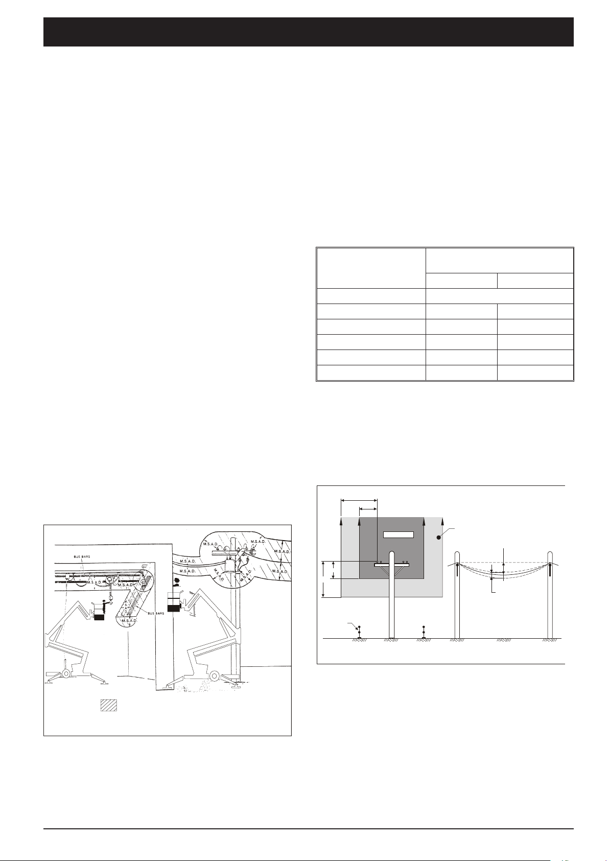
ANSI publications dene minimum distances that
must be observed when working near bus bars
and energised power lines. Figure 1 and Table 1
are reprinted courtesy of the Scaffold industry
Association, ANSI/SIA A92.5.
Voltage Range
(Phase to Phase
0 to 300V Avoid Contact
Over 300V to 50kV 10 3.05
Over 50kV to 200kV 15 4.60
Over 200kV to 350kV 20 6.10
Over 350kV to 500kV 25 7.62
Over 500kV to 750kV 35 10.7
Table 1 - Minimum Safe Approach Distance
ANSI 92.5
Australian Standard AS2550.10 denes minimum
distances that must be observed when working near
live aerial conductors up to and including 133kV
(see Figure 2).
CLEARANCES FROM LIVE AERIAL CONDUCTORS
6.4
3
Minimum Safe Approach
Distance
Feet Metres
(Dimensions are in metres)
Denotes prohibited zone
Caution: - Diagrams shown are only for purposes of illustrating
M.S.A.D. Work positions, not all work positions.
Figure 1 - Minimum Safe Approach Distance
ANSI A92.5
Spotter
required
zone
Sag
Variations
in Sag
3
6.4
Personal
protection
barriers
No go zone
n
FRONT VIEW SIDE VIEW
Distribution Lines Up to and Including 133kV
Figure 2 - Minimum Safe Approach Distance
AS 2550.10
Rev C page 1-1
Page 14

1. Safety
■ Pre-start Inspection
At the start of each work shift, the TL39T shall be
given a visual inspection and function test. See
the “Pre-operational Inspection and Maintenance”
chapter 7, in this manual for a list of items to
inspect and test.
! WARNING
DO NOT operate the TL39T unless you are
trained and authorized, understand the
operation characteristics of the TL39T, and
have inspected and tested all functions to be
sure they are in proper working order.
! DANGER
NEVER use an TL39T that has a known fault
or is malfunctioning in any way until the
machine has been repaired by a qualied
technician.
Operating a machine in faulty condition could
result in death or serious injury.
NOTE:
Whilst some of the safety rules and guidelines that
follow may not apply specically to this machine
(e.g. references to driving) they are included as part
of an overall safety strategy relating to the use of
elevating work platforms.
■ Work Place Inspection and Practices
Do not use the TL39T as a ground for welding.
Ground to the work piece.
Be fore the TL39T is used, and during use, check
the area in which the TL39T is to be used for
possible hazards such as, but not limited to:
● Drop-offs or holes.
● Side slopes.
● Bumps and oor obstructions.
● Debris.
● Overhead obstructions and electrical
conductors.
● Hazardous locations.
● Inadequate surface and support to withstand
all load forces imposed by the aerial platform
in all operating congurations.
● Wind and weather conditions.
● Presence of unauthorized persons.
● Other possible unsafe conditions.
location according to ANSI/NFPA 505.
Any TL39T operated in a hazardous location must
be approved and of the type required by ANSI/
NFPA 505.
While operating the MHP a recommended safety
practice is to have trained and qualied personnel
in the immediate work area of the TL39T to:
● Help in case of an emergency.
● Operate emergency controls as required.
● Watch for loss of control by platform operator.
● Warn the operator of any obstructions or
hazards that may not be obvious to them.
● Watch for soft terrain, sloping surfaces, drop-
offs, etc., where stability could be jeopardized.
● Watch for bystanders and never allow anyone
to be under, or to reach through the booms
while operating the aerial platform.
! DANGER
Pinch points may exist between moving
components. Death or serious injury can
result from becoming trapped between
components, buildings, structures, or other
obstacles. Make sure there is sufcient
clearance around the machine before moving
the chassis, booms, or platform. Allow
sufcient room and time to stop movement
to avoid contact with structures or other
hazards.
Keep ground personnel from under the platform
when the plat form is raised.
Secure all accessories, containers, tools, and other
materials in the platform to prevent them from
accidentally falling or being kicked off the platform.
Always look in the direction of travel. Drive with
care and at speeds compatible with the work-place
conditions. Use caution when driving over rough
ground, on slopes, and when turning.
Do not engage in any form of “horseplay” or “stunt
driving” while operating the TL39T.
Do not permit riders on the machine anyplace other
than on the platform.
Remove all loose objects stored in or on the
machine, particularly in the platform. Remove all
objects which do not belong in or on the machine.
Before the TL39T is used, determine the hazard
classication of any particular atmosphere or
page 1-2 Rev C
Page 15

1. Safety
Never steady the platform by positioning it against
another platform.
Do not operate an TL39T that is damaged or not
functioning properly. Do not use the MHP until
the machine has been repaired by a qualied
maintenance person.
Do not operate a TL39T that does not have all its
decals and placards attached and legible.
Watch for by stand ers and never allow anyone to
be under, or to reach through, the machine and its
equipment while operating.
Use the recommended transport device when
loading the machine.
■ Operation
If you encounter any suspected malfunction of the
aerial platform, or any hazard or potentially unsafe
condition relating to capacity, intendeduse, or safe
operation, cease operation immediately and seek
assistance from management.
Use three points of sup port when get ting on or off
the platform (two hands and one foot or a similar
set of points). Keep the platform clean.
Do not operate the TL39T from a position on trucks,
trailers, railway cars, oating vesels, scaffolds,
or similar equipment unless the application is
approved in writing by Snorkel.
Care shall be taken to prevent rope, electric cords,
and hoses, etc., from becoming entangled in the
aerial platform. If the platform or elevating assembly
becomes caught, snagged, or otherwise prevented
from normal motion by an adjacent structure or
other obstacle such that control reversal does
not free the platform, remove all personnel from
the platform before attempts are made to free the
platform using ground controls.
Under normal working conditions it is best not to
transfer from the platform to another structure or
vice versa, unless that is the safest way to do the
job. Each situation must be judged separately
taking the work environment into account. The
following guidelines apply:
1. Where possible, place the work platform over
a roof or walking structure to do the transfer.
2. Transfer your anchorage from one structure to
another before you step across.
Maintain a rm footing on the platform oor. Operate
the controls slowly and deliberately to avoid jerky
and erratic operation. Always stop the controls in
neutral before going in the opposite direction.
Do not dismount while the platform is in motion or
jump off the machine.
Do not start until all personnel are clearly away from
the machine.
Never cover the oor grating or otherwise obstruct
your view below. Make sure the area below the
platform is free of personnel before lowering.
■ Tipover and Falling Hazards
Operate the MHP only on a rm, at, level surface
capable of withstanding all load forces imposed by
the TL39T in all operating conditions.
! DANGER
The MHP can tip over if it becomes unstable.
Death or serious injury can result from a
tip-over accident. Do not drive or position
the MHP platform for elevated use near any
drop-ff, hole, slope, soft or uneven ground, or
other tip-over hazard.
3. Remember, you might be departing the work
platform to a structure where fall arrest is
required.
4. Do not climb over or through the guardrails.
Use the platform entrance.
All platform occupants MUST wear and use fall
restraint. At tach fall restraints to the platform
lanyard anchor points.
Do not exceed the unrestricted platform capacity as
indicated on the capacity placard at the entrance
to the platform. Do not carry loads from any point
outside of the platform.
Make sure that all protective guards, cowlings, and
doors are in place and secure. Be sure the guardrail
system, including the gate, is in place and secure.
Do not climb on the guardrails or use ladders,
planks, or other devices to extend or increase your
work position from the platform.
Do not use the MHP as a crane, hoist, or jack, or for
any other purpose other than to position personnel,
their tools, and materials.
Do not operate the TL39T in winds, or wind gusts,
of 28 mph, 45kph 12.5 m/s) or more.
! DANGER
Do not add banners, ags, screens or shelters
etc., to areas of the MHP that are exposed to
Rev C page 1-3
Page 16
1. Safety
wind forces as this will increase the wind load
ing and effect stability
■ General Safety Precautions
Do not modify the TL39T in any way.
When parts or components are replaced, they shall
be identical or equivalent to original Snorkel parts
or components.
Do not override any of the safety features of the
TL39T.
■ Hydraulic System Precautions
The hydraulic system contains hoses with hydraulic
uid under pressure.
! DANGER
Hydraulic uid escaping under pressure can
have enough force to inject uid into the
esh. Serious infection or reaction can result
if medical treatment is not given immediately.
In case of injury by escaping hydraulic uid,
seek medical attention at once.
engine in an enclosed area or indoors without
adequate ventilation.
Only refuel your MHP out doors in a clear area void
of gas fumes or spilled gas.
Never remove the fuel cap or refuel a gasoline
engine while the engine is running or hot. ALWAYS
allow the engine to cool before refueling. Never
allow fuel to spill on hot machine components.
! DANGER
DO NOT smoke or permit open ames while
fueling or near fueling operations.
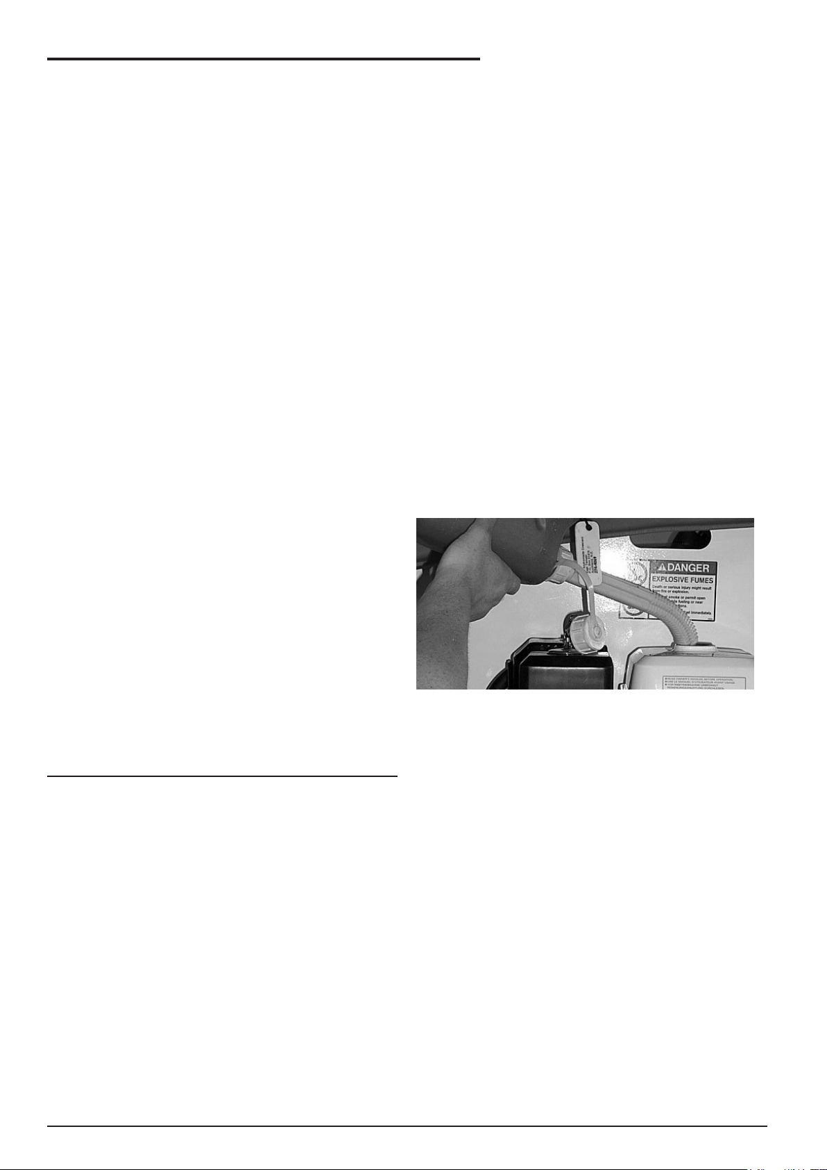
Maintain control of the fuel ller nozzle when lling
the tank.
! CAUTION
ENSURE you use an approved fuel container
with appropriate fuel ller nozzle (see picture
below)
Do not ll the fuel tank to capacity. Allow room for
DO NOT place your hand or any part of your body
in front of escaping hydraulic uid. Use a piece of
cardboard or wood to search for hydraulic leaks.
Do not attempt repairs to hydraulic systems unless
you are trained. Refer to experienced repair
personnel for help.
■ Fire Prevention
Never operate your MHP near a ame or spark.
Hydraulic oil and gasoline are ammable and can
explode.
NOTE:
This machine is equipped with an internal
combustion engine (in it’s standard conguration)
and should not be used on or near any unimproved
forest-covered, brush-covered or grass covered
land unless the engine’s exhaust system is
equipped with a spark arrester meeting applicable
laws. If a spark arrester is used, it should be
maintained in effective working order by the
operator.
■ Engine and Fuel Handling Precautions
expansion.
If gasoline is spilled, clean up spilled fuel
immediately, push/tow the MHP away from the area
of the spill and avoid creating any source of ignition
until the spilled fuel has evaporated.
Tighten the fuel tank cap securely. If the fuel cap is
lost, replace it with an approved cap from Snorkel.
Use of a non-approved cap without proper venting
may result in pressurization of the tank.
Never use fuel for cleaning purposes.
For diesel engines, use the correct fuel grade for
the operating season.
! WARNING
Engine exhaust contains carbon monoxide, a
poisonous gas that is invisible and odorless.
Breathing engine exhaust fumes can cause
death or serious illness. Do not run the
page 1-4 Rev C
Charge batteries in a well ventilated area free of
ame, sparks, or other hazards that might cause
re or explosion.
■ Batteries
! WARNING
Page 17

1. Safety
Batteries give off hydrogen and oxygen that
can combine explosively. Death or serious
injury can result from a chemical explosion.
Do not smoke or permit open ames or
sparks when checking batteries.
! CAUTION
Battery acid can damage the skin and eyes.
Serious infection or reaction can result if
medical treatment is not given immediately.
Wear face and eye protection, rubber gloves
and protective clothing when working near
batteries.
! CAUTION
If acid contacts your eyes, ush immediately
with clear water and get medical attention. If
acid contacts your skin, wash off immediately
with clear water.
■ Height Restriction
See the Options chapter page 5 for details
concerning this kit.
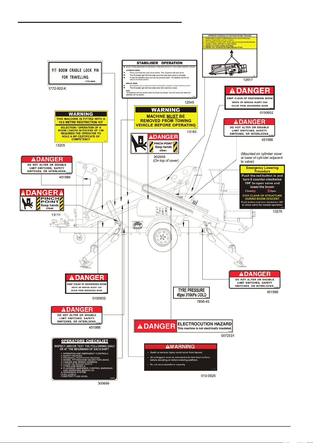
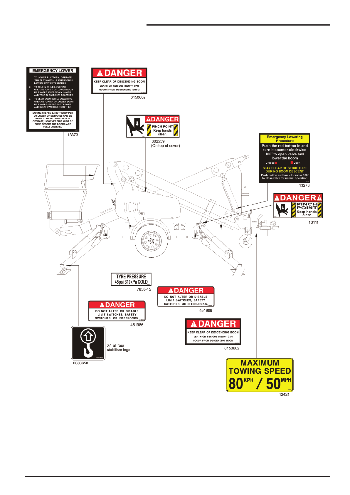
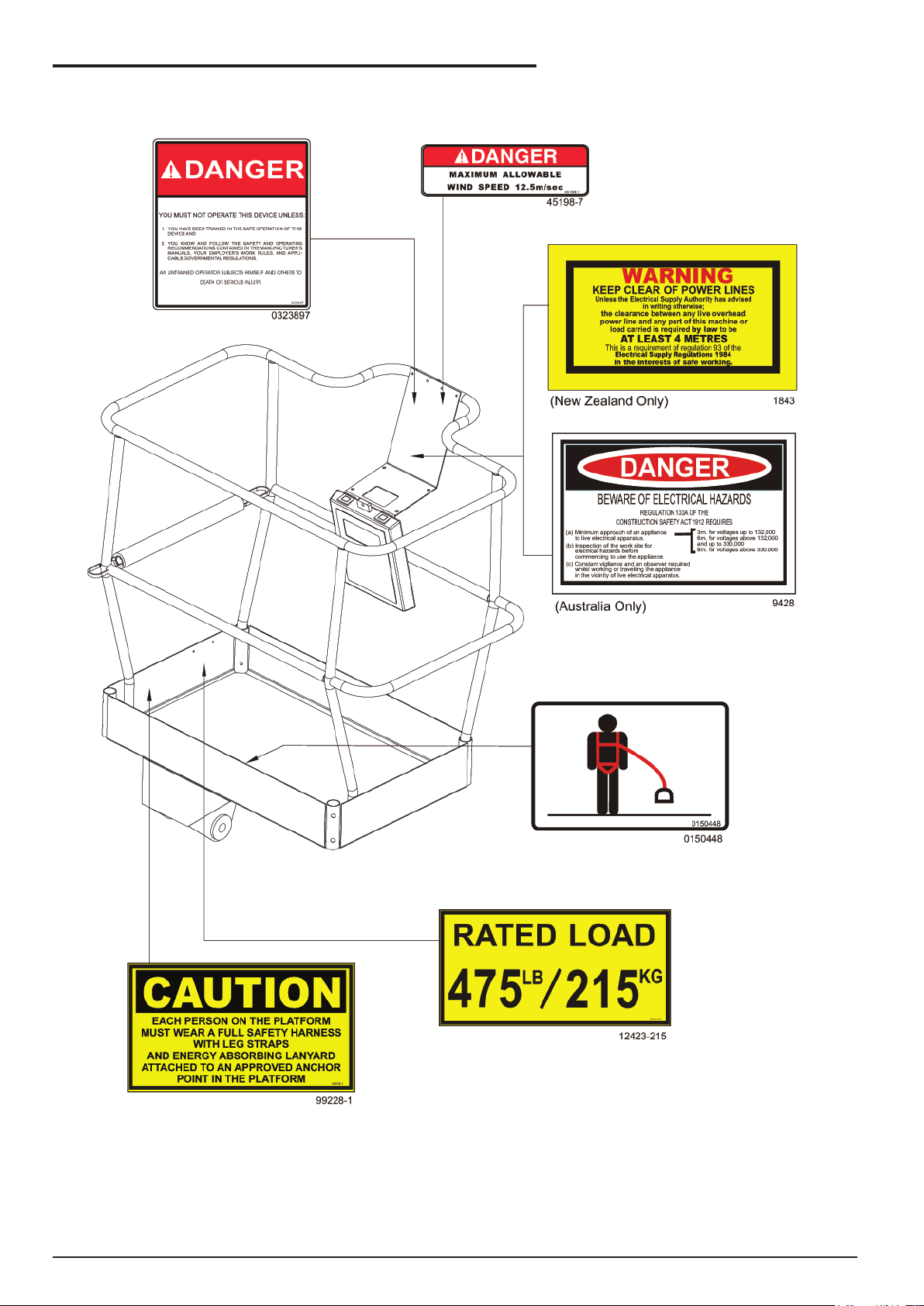
■ Safety Decals and Placards
There are a number of safety decals and
placards on the TL39T. Their locations and
descriptions are shown in this section on the
following pages. Take time to study them.
! CAUTION
Be sure that all the safety decals and
placards on the TL39T are legible.
Clean or replace them if you cannot read the
words or see the pictures. Clean with soap &
water and a soft cloth. Do not use solvents.
! IMPORTANT
The height restrictor tted to the standard
TL39T, is not the same device as the 10.9m
restriction kit, although both of these devices
achieve the same result of restricting the
maximum height of the platform to 10.9m
from the ground.
This is to allow the unit to be operated by
unlicensed operators in accordance with Australian
legislation.
! WARNING
An Australian operator MUST hold a WP
Certicate of Competency in order to operate
the machine at heights in excess of 11m.
■ Height Restriction on TL39T
The TL39T (in standard mode) is tted with a
restrictor in the upper hydraulic lift cylinder to keep
the platform to a maximum height of 10.9m.
■ 10.9 Metre Restriction Kit
Machines that are built for the Australian market
may be tted with a 10.9m restriction kit.
This kit which can be tted to the MHP14AT is tted
to restrict the maximum height to the platform oor
at 10.9 m from the ground.
Note:
Rev C page 1-5
Page 18
1. Safety
page 1-6 Rev C
Page 19
1. Safety
Rev C page 1-7
Page 20
1. Safety
page 1-8 Rev C
Page 21
2. Safety Devices
■ Safety Device Information
For emergency operation controls and procedures,
see the “Emergency Operation” chapter 9, in this
manual.
The devices listed in this chapter are safety
devices.
They are on the TL39T to increase safety in the
work place for both the operator and other people
near the TL39T.
! CAUTION
DO NOT bypass, disable, modify, or ignore
any of these devices. Check them carefully
at the start of each work shift to see that they
are in working order (see “Pre-operational
Inspection” chapter 7). If any is found
to be defective, remove the TL39T from
service immediately until a qualied service
technician can make repairs.
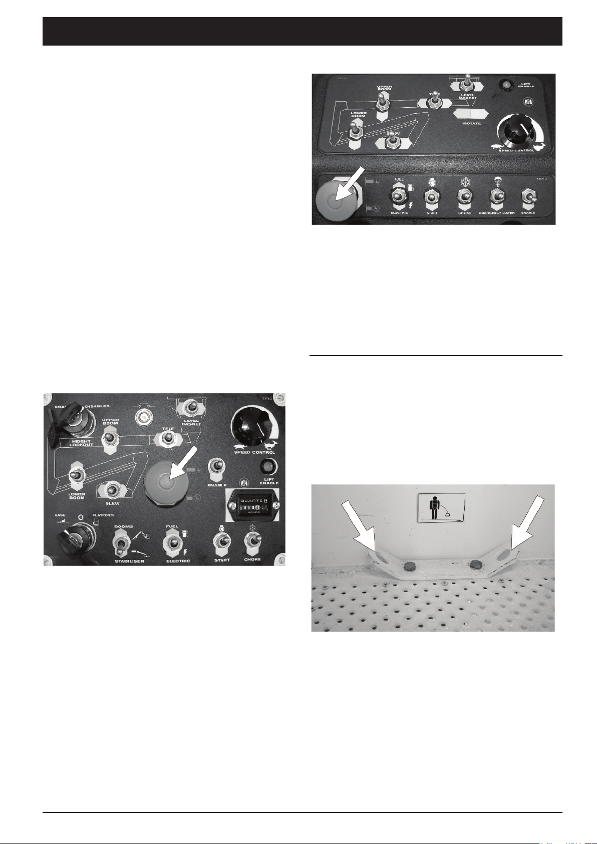
■ Emergency Stop Switches
❑ At ground control box
❑ At platform control box
Figure 2.2 - Emergency Stop Switch at
Platform Control Box
Press the red EMERGENCY STOP button in, at
any time, under any conditions, and the entire
machine stops, and nothing moves. This switch
must be out (on) for anything on the TL39T to work.
Pull the switch and it will pop out (on).
NOTE:
The ground control box is designed to override
the platform control box. If the platform control box
EMERGENCY STOP switch is in (off) the ground
control box can still be used to start and operate
the TL39T.
Figure 2.1 - Emergency Stop Switch at
Ground Control Box
Press the red EMERGENCY STOP button in, at
any time, under any conditions, and the entire
machine stops, and nothing moves. This switch
must be out (on) for anything on the TL39T to work.
Pull the switch and it will pop out (on).
■ Other Safety Devices
❑ Lanyard anchor points
Figure 2.3 - Lanyard Anchor Points
All personnel on the platform should attach their
fall restraint lanyards to one of the lanyard anchor
points.
The lanyard anchors are located at the rear of the
platform oor.
Rev C page 2-1
Page 22
2. Safety Devices
❑ Gravity gate
Figure 2.4 - Gravity Gate
The gravity gate is the place in the platform
guardrail system where you should enter and leave
the platform. Raise the gate and step under it onto
the platform. Once you have entered the platform
and attached your fall restraint lanyard to an anchor
point, check to see that the gravity gate has fallen
back into place.
It is tted to restrict the maximum height to the
platform oor to 10.9m from the ground. This is
to allow the unit to be operated by unlicensed
operators in accordance with Australian legislation.
Note - Height Restriction Kit
See the Options chapter page 5 for details
concerning this kit.
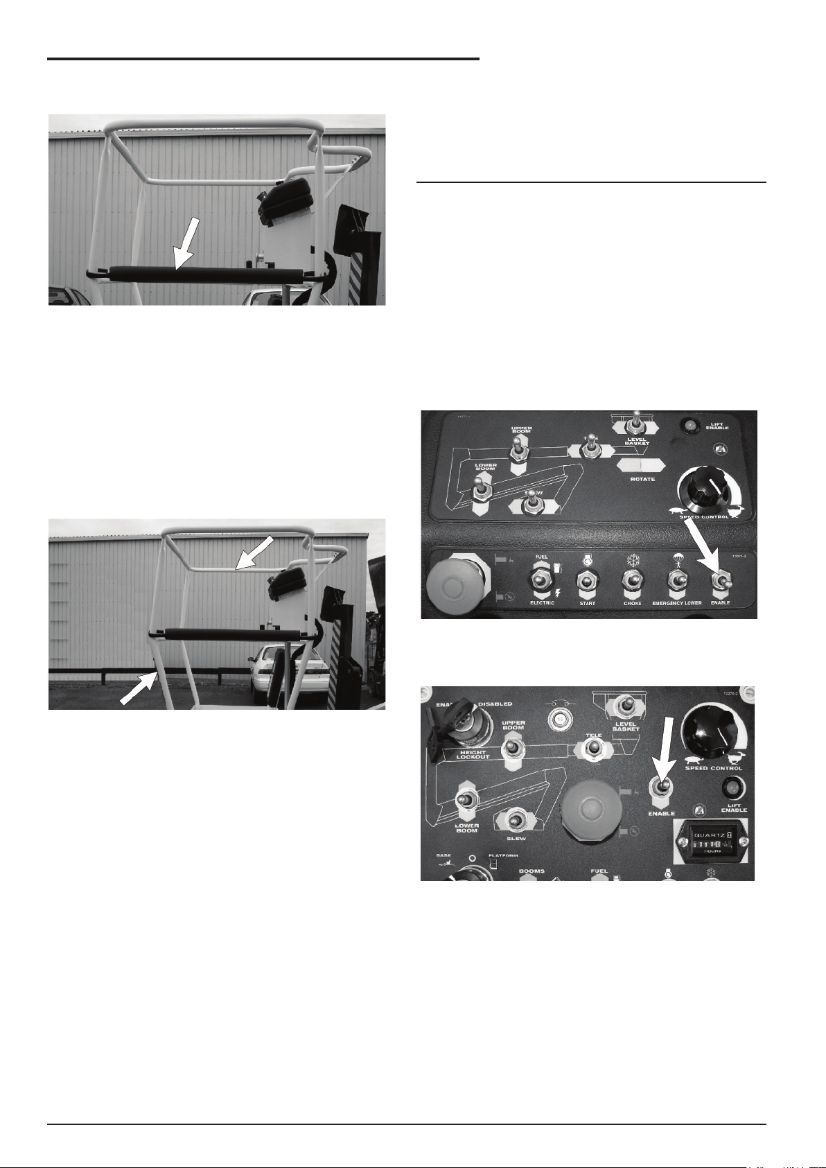
❑ Enable switch
The enable switch must be operated in conjunction
with the boom/platform moving function you select.
The purpose of this switch is to prevent the platform
from moving if something or someone accidentally
pushes one of the boom/platform moving controls.
There are enable switches tted to both the Upper
and Lower Control Boxes.
❑ Guardrails
Figure 2.5 - Guardrails
The guardrails help protect you from falling off
the platform. Be sure the guardrails are properly
installed and that the gravity gate or swinging gate
is in place.
❑ Height restriction on TL39T
The TL39T (in standard mode) is tted with a
restrictor in the upper hydraulic lift cylinderto keep
the platform to a maximum height of 10.9m.
❑ 10.9m height restriction kit (Option)
Figure 2.6 - Enable Switch, Platform Control
Box
Figure 2.7 - Enable Switch, Ground Control
Box
This kit may be tted to machines manufactured for
the Australian market.
page 2-2 Rev C
Page 23
2. Safety Devices
❑ Enable switch (foot) – Optional
Figure 2.8 - Enable Switch (Foot)
The foot switch performs the same function as
the standard enable switch described above.
Stepping on the foot switch is an action that must
be performed, at the same time as another action,
to make the booms/platform move.
Note:
If you have the optional ‘foot switch’ tted the
Enable switches on the Upper Control Box and the
Ground Control Box will still function.
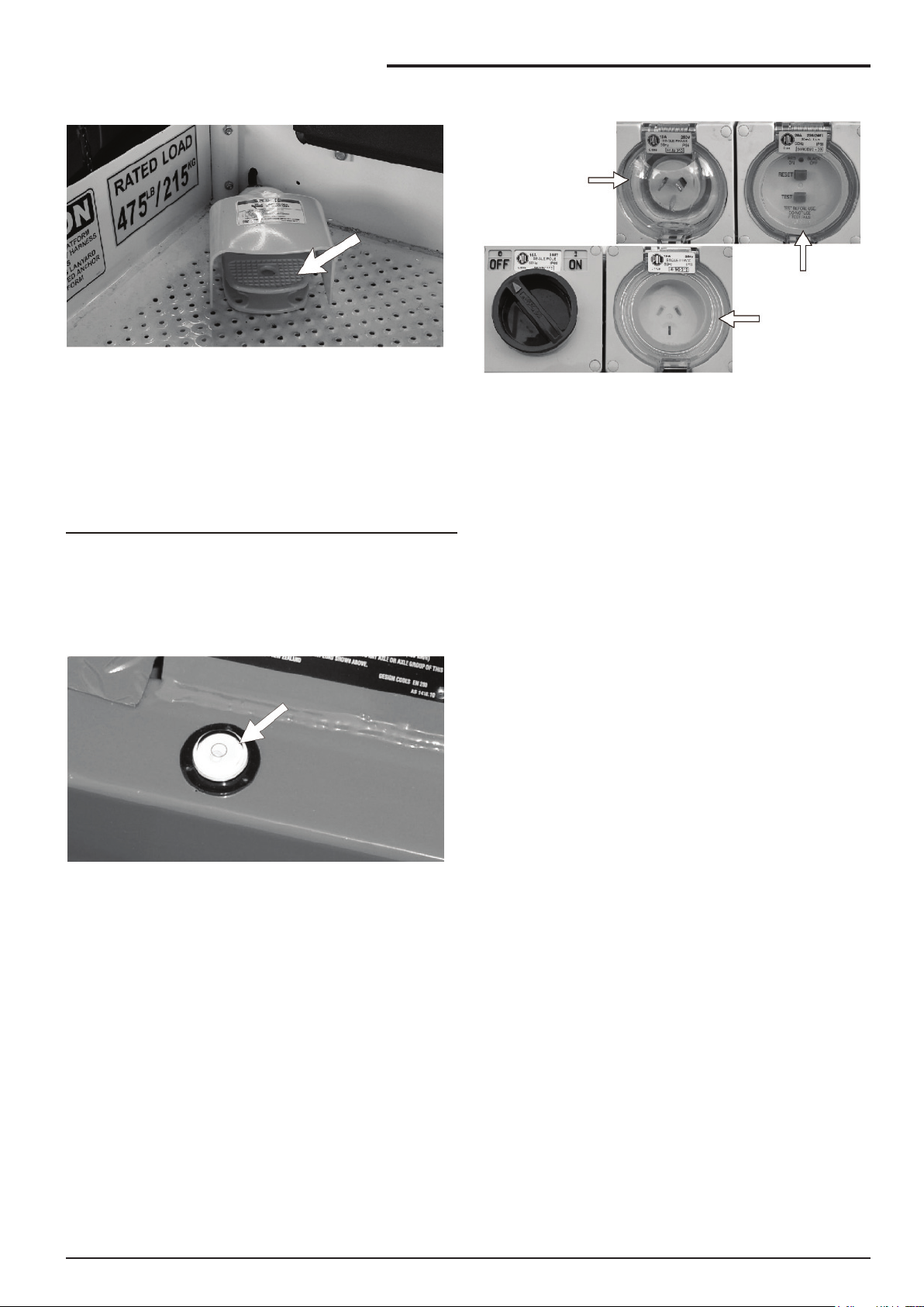
❑ RCD/ELCB AC outlet (Option)
Power Input
Connector
At Base
RCD At Base
Power Outlet
At Platform
Figure 2.10 - RCD/ELCB AC Outlet, Vertical
Mounting
The RCD (Residual Current Device) is located at
the base and will protect against short circuits to
earth. When there is a short circuit the RCD will
shut down the 230v AC power to the platform outlet.
To reset the outlet disconnect the power tool lead
from the platform box and reset the RCD at the
base. If the problem persists call a trained service
technician.
❑ Bubble level
Figure 2.9 - Bubble Level
A bubble level is located on the trailer side rail,
beside the outrigger controls. Watch the bubble
level while you set the stabilisers. Lower the
stabilisers, one at a time, just enough to center the
bubble in the circle on top of the guage. When the
bubble is centered the platform is level and can be
safely raised.
❑ Flashing light (Option)
The ashing light alerts people that the booms
/ platform of the TL39T are moving. The light
ashes at about one ash per second any time the
MASTER KEY switch is on. There is no ON/OFF
switch for the ashing light, it cannot be turned off
while the TL39T is running.
Rev C page 2-3
Page 24

Page 25

3. Specications
The Snorkel TL39T are boom supported elevating work platforms built to conform to Australian Standard
AS1418-10 Elevating Work Platforms.
NOTE:
For further details regarding lubricants, maintenance schedules and service please refer to the
Maintenance and Repair Parts Manual for this machine.
■ General Specications
■ Specications MHP14AT
SPECIFICATIONS MHP14AT
Nominal working height 13.5m 44.3’
Maximum height to basket oor 11.5m 37.7’
Maximum outreach 6.4m 21.0’
Maximum width of base
Stabilisers retracted
Stabilisers extended
1.6m
3.6m
5.2’
11.8’
Safe working load (unrestricted) 215kg 474lbs
Platform size 1.15 x 0.70m 3.8’ x 2.3’
Construction Steel Steel
Travelling height 2m 6.6’
Overall length 4.7m 15.4’
Maximum towing speed 80km/h 50mph
Turntable rotation 540o Non continuous
Trailer tongue weight (approximately) Less than 100kg Less than 225lbs
Maximum rated axle capacity 2000kg 4409lbs
Insulation rating Nil (on standard models)
Weight 1460kg (Petrol model) 3218lbs (Petrol model)
Rev C page 3-1
Page 26

3. Specications
■ Specications TL39T
SPECIFICATIONS TL39T
Nominal working height 12.9m 42.3’
Maximum height to basket oor 10.9m 35.8’
Maximum outreach 6.4m 21.0’
Maximum width of base
Stabilisers retracted
Stabilisers extended
Safe working load (unrestricted) 215kg 474lbs
Platform size 1.15 x 0.70m 3.8’ x 2.3’
Construction Steel Steel
Travelling height 2m 6.6’
Overall length 4.7m 15.4’
Maximum towing speed 80km/h 50mph
Turntable rotation 540o Non continuous
Trailer tongue weight (approximately) Less than 100kg Less than 225lbs
Maximum rated axle capacity 2000kg 4409lbs
Insulation rating Nil (on standard models)
Weight 1460kg (Petrol model) 3218lbs (Petrol model)
❑ Recommended Hydraulic Oil
Shell Tellus 32 or Castrol AWS 32 or similar
1.6m
3.6m
5.2’
11.8’
page 3-2 Rev C
Page 27

■ Engine Data
Engine Make Honda (gasoline)
Model GX 160
Engine type 4-stroke, over head valve, 1 cylinder
Displacement 163 cm3 (9.9 cu-in)
Bore x Stroke 68 x 45 mm (2.7 x 1.8 in)
Max. output 4 kW/4,000 rpm
Max. torque 1.1 kg-m (8.0 ft-lb)/ 2500 rpm
Fuel gasoline
Fuel Grade automotive gasoline (unleaded or low leaded preferred)
Fuel consumption 230 g/PSh
Cooling system Forced air
3. Specications
Ignition system Transistor magneto
PTO shaft rotation Counterclockwise
Oil Capacity 0.60 litres (0.60 US qt, 0.53 Imp qt)
Oil Grade SAE 10W-30
Rev C page 3-3
Page 28

3. Specications
■ Working Envelope - TL39T
Working Curve
10.9 Restricted
page 3-4 Rev C
Dimensions in metres
Page 29

■ Nomenclature
❑ Right side view of machine
3. Specications
Tow
coupling
Draw bar
Outrigger
controls
Ground
controls
Platform
controls
Platform
Trailer
Outriggers (4)
❑ Booms identication
Floating
Turret
Upper Lift
Cylinder
Upper boom
Lower
boom
Lower Lift
Cylinder
Telescoping
Boom
Rev C page 3-5
Page 30

3. Specications
❑ Left side view of machine
Outriggers
Oil tank
Hand
brake
Engine
Jockey
Whee
page 3-6 Rev C
Page 31

4. Gauges
■ Hourmeter
Figure 4.1 - Hourmeter
The hour meter is basically an electric clock. It
accumulates time when the master key switch is
turned on. The hour meter can not be reset. An
MHP qualied service technician can use it to tell
when it is time for the periodic maintenance listed in
the maintenance manual.
■ Level Bubble
■ Hydraulic Oil Level
Figure 4.3 - Hydraulic Oil Level
The hydraulic oil level gauge is attached to the side
of the hydraulic tank. Read it only when the booms
are fully lowered and the stabilisers are raised in
the travel position.
The hydraulic oil level should be between the two
marks on the decal.
If necessary, add hydraulic oil at the ller cap. see
the “Specications” chapter 3, for type and grade of
hydraulic oil.
Figure 4.2 - Level Bubble
A level bubble is mounted on the trailer base. Watch
the bubble while you set the stabilisers. Lower
the stabilisers, front ones rst, one at a time just
enough to center the bubble in the circle on top of
the gauge. When the bubble is central the platform
is level and the platform can be safely raised.
Rev C page 4-1
Page 32

Page 33

5. Shut-offs and Circuit Breakers
■ RCD/ELCB Outlet (option)
Figure 5.1 - RED/ELCB Outlet
The RCD (Residual Current Device) is located at
the base and will protect against short circuits to
earth. When there is a short circuit the RCD will
shut down the 230v AC power to the platform outlet.
To reset the outlet disconnect the power tool lead
from the platform box and reset the RCD at the
base.
Figure 5.3 - Stabilisers
The TL39T booms cannot be raised unless the
stabilisers are set and the lift enable light on the
lower control box is lit. Once the booms are raised
from the stowed position the stabilisers become
disabled until the booms are stowed in the travel
position.
If the problem persists call a trained service
technician.
■ Main Circuit Breaker
Figure 5.2 - Main Circuit Breaker
There is only one circuit breaker, on a standard
TL39T, that is accessible to the operator. Its
purpose is to protect the electrical circuits from
electrical overloads. When the circuit breaker trips
(pops out) push it back in then attempt to use the
TL39T. If the circuit breaker trips a second time,
take the TL39T out of service and refer the problem
to a qualied trained service technician for repair.
■ Stabilisers
Rev C page 5-1
Page 34

Page 35

6. Controls
■ Controls Description
This chapter explains what each control does.
This chapter DOES NOT explain how to use
the controls to produce useful work, refer to the
“Operation” chapter 8 for that after you have read
this chapter.
❑ Controls and Control Decal Locations
For optional equipment controls, see the “Options”
chapter.11
See the “Emergency Operation” chapter 9-1 for the
location of the emergency bleed down control and
for correct emergency bleed down procedures.
The main operating functions of an TL39T can be
controlled from the ground control box or from the
platform control box.
Ground Controls
Optional Automatic Stabiliser Controls
Platform Controls
Manual Stabiliser Controls
Rev C page 6-1
Page 36

6. Controls
■ Ground Control Box
Controls for operating the TL39T from the ground
controls are located on the right side of the column.
❑ Lower controls / indicators:
❍ Emergency stop switch
❍ Platform / base selector switch
❍ Choke
❍ Master key switch
❍ Boom speed rheostat
❍ Stabiliser / boom selector switch
❍ Lower boom switch
❍ Upper boom switch
❍ Tele boom switch
❍ Level basket switch
❍ Slew switch
❍ Enable switch
❍ Lift enable indicator
❍ 10.9m height lockout switch (Option)
❍ Fuel / electric selector switch (Option)
❍ Overload protection indicator (Option)
❍ Emergency lower valve
Figure 6.2 - Lower Control Box Controls
2. Platform/Base Selector : Must be in the
BASE position for the ground control box to
work. The switch MUST be in the PLATFORM
position for the platform control box to work.
NOTE: This switch also acts as the ‘master
key switch’. Turning the key to the central
position and removing the key will effectively
disable all operations.
3. Choke/Cold Start: Hold the switch DOWN
while you start an engine that is at ambient air
temperature (a “cold” engine). This will choke
the engine.
4. Start Switch: Press and hold this switch
DOWN to operate the starter motor for the
MHPAT.
5. Boom Speed: This control determines how
fast the booms move. Set it to SLOW (turtle)
until you are very familiar with the way the
machine works or if the platform is working in
dangerous or cramped surroundings.
6. Stabliser / Boom Selector Switch: Must be
in Stabliser position (DOWN) for the stabilisers
to work. Once the stabilisers are down and set
the switch must be placed in the boom (UP)
position for the booms to work.
1. Emergency Stop: Press the red
EMERGENCY STOP button in, at any time,
under any conditions, and the entire machine
stops, and nothing moves. This switch must
be out (on) for anything on the MHP to work.
Pull the switch and it will pop out (on).
Control switches 7 through 11 are the platform
moving switches. Each is a three position,
momentary contact, normally OFF switch.
7. Lower Boom : UP raises the lower boom.
DOWN lowers the lower boom.
8. Upper Boom: UP raises the upper boom.
DOWN lowers the upper boom.
9. Tele Boom: LEFT retracts the telescoping
boom. RIGHT extends the telescoping boom.
10. Level Basket: LEFT tilts the basket forwards.
RIGHT tilts the basket backwards
11. Slew: LEFT rotates the entire turntable and
boom to the left. RIGHT rotates the entire
turntable and boom to the right.
12. Enable Switch: The enable switch must
be pressed DOWN in conjunction with the
boom/platform moving function you select.
The purpose of this switch is to prevent the
platform/booms from moving if something
or someone accidentally pushes one of the
boom/platform moving controls. The boom/
platform moving switches will not operate
unless the enable switch is held down at the
same time.
page 6-2 Rev C
Page 37

6. Controls
13. Lift Enable Indicator: The platform can only
be raised when this light is lit. When this light
is not lit the platform will not raise because the
stabilisers are not properly set.
14. Height Lock out Switch (Option): This
switch (when tted) limits the maximum height
of the boom to 10.9 metres (see Options
Chapter page 5)
15. Fuel / Electric Selector Switch (Option):
This switch (when tted) allows switching
between different motive sources (see Options
Chapter)
16. OverloadIndicator (Option): This indicator
(when tted) illuminates when the platform is
over loaded (see Options Chapter).
17. Emergency Lower Controls: Allows the
platform to be lowered in the event of an
emergency (see Chapter 9 “Emergency
Operation”) for details of emergency lowering
procedures.
■ Platform Control Box
Controls for operating the TL39T from the platform
(upper controls) are located on the platform control
box, with the exception of the foot switch (option)
which is on the platform oor and the manual
basket rotator which is mounted on the front of the
basket.
❑ Upper controls / indicators:
❍ Emergency stop switch
❍ Choke
❍ Start switch
❍ Boom speed rheostat
❍ Emergency lower switch
❍ Lower boom switch
❍ Upper boom switch
❍ Tele boom switch
❍ Level basket switc
❍ Slew switch
❍ Enable switch
❍ Enable foot switch (option)
❍ Lift enable indicator
❍ Fuel / electric selector switch (option)
❍ Overload indicator (option)
❍ Rotate switch (future option)
❍ Manual Rotator
Figure 6.3 - Ground Controls, Emergency
Bleed Down Control Valve, Lower Boom
Figure 6.4 - Ground Controls, Emergency
Bleed Down Control Valve, Upper Boom
Figure 6.5 - Upper Control Box Controls
1. Emergency Stop: Press the red
EMERGENCY STOP button in, at any time,
under any conditions, and the entire machine
stops, and nothing moves. This switch must
be out (on) to start or run the MHP from the
platform control box. Pull the switch and it will
pop out (on). Press the switch in (off) if the
platform is to stay in one position for a long
time. That will turn the engine off and and
save fuel.
Rev C page 6-3
Page 38

6. Controls
Figure 6.5 - Upper Control Box Controls
2. Choke/Cold Start: Hold the switch DOWN
while you start an engine that is at ambient air
temperature (a “cold” engine). This will choke
the engine.
3. Start: Press and hold this switch DOWN to
operate the starter mo tor for the MHPAT.
4. Boom Speed: This control determines how
fast the booms move. Set it to SLOW (turtle)
until you are very familiar with the way the
machine works or if the platform is working in
dangerous or cramped surroundings.
9. Level basket: LEFT tilts the basket forwards,
RIGHT tilts the basket backwards.
10. Slew: LEFT rotates the entire turntable and
boom to the left. RIGHT rotates the entire
turntable and boom to the right.
11. Enable: The enable switch must be pressed
DOWN in conjunction with the boom/platform
moving function you select. The purpose of
this switch is to prevent the platform/booms
from moving if something or someone
accidentally pushes one of the boom/platform
moving controls. The boom/platform moving
switches will not operate unless the enable
switch is held down at the same time.
12. Enable Foot Switch (Option): The foot switch
performs the same function as the standard
enable switch described above. Stepping
on the foot switch is an action that must be
performed, at the same time as one of the
boom/platform moving switches is operated.
1. Emer gency Lower Controls: If the engine
stops and can not be restarted, or some
other emergency prevents the platform
being lowered in the normal way, operate
the EMERGENCY LOWER switch and the
ENABLE switch together and this will cause
the upper and lower booms to descend.
To slew during the emergency lower operate
the EMERGENCY LOWER, ENABLE, UPPER
or LOWER BOOM UP, and SLEW switches
together.
To tele in during the emergency lower operate
the EMERGENCY LOWER, ENABLE, UPPER
or LOWER BOOM UP, and TELE switches
together.
See Chapter 9 “Emergency Operation” for details of
emergency lowering procedures from the platform.
Items 6 through 10 are the platform moving
switches. Each is a three position, momentary
contact, normally OFF switch.
6. Lower Boom: UP raises the lower boom.
DOWN lowers the lower boom.
7. Upper Boom: UP raises the upper boom.
DOWN lowers the upper boom.
Figure 6.6 - Upper Controls - Foot Switch
Note:
If you have the optional ‘foot switch’ tted this is an
“and” option and the Enable switchs on the Lower &
Upper Control Boxes will still function.
13. Lift Enable Indicator: The platform can only
be raised when this light is lit. When this light
is not lit the platform will not raise because the
outriggers are not properly set.
14. Fuel / Electric Selector Switch (Option):
This switch (when tted) allows switching
between different motive sources (see Options
Chapter).
15. OverloadIndicator(Option): This indicator
(when tted) illuminates when the platform is
over loaded (see Op tions Chapter).
8. Tele Boom: LEFT retracts the telescoping
boom. RIGHT extends the telescoping boom.
page 6-4 Rev C
Page 39

16. Rotator Switch (Future Option):
LEFT rotates the platform to the left.
RIGHT rotates the platform to the right.
NOTE: This switch is not currently available
as an option.
17. Manual Platform Rotator: Turn the handle to
the RIGHT to rotate the platform to the right.
Turn the handle to the LEFT to rotate the
platform to the left. (In sert shows platform
rotator handle folded down).
6. Controls
Figure 6.9 - Decal Stabiliser Controls
(Manual)
NOTE:
Ensure that the front stabilisers are lowered rst to
prevent damage to the jockey wheel.
Figure 6.7 - Manual Platform Rotator
■ Stabiliser Controls (Manual)
MANUAL STA-
BILISER VALVE
LEVERS
Figure 6.8 - Stabiliser Controls (Manual)
1. Boom / Stabiliser Switch: Ensure the boom/
stabiliser switch on the lower control box is
set to stabiliser (see Item 6 on page 2 of this
chapter)
Figure 6.10 - Stabiliser Controls (Manual)
2. Valve Levers: Operate the valve levers to
activate the stabilisers and level the machine.
3. Bubble level: Use the bubble level to level
the machine.
Figure 6.11 - Bubble Level
Rev C page 6-5
Page 40

6. Controls
■ Self Levelling Stabilisers (Option)
Figure 6.12 - Self Levelling Stabiliser
Controls
1. Auto Level / Stow Switch: Select either
auto level or auto stow, to raise or lower the
stabilisers automatically.
2. Manual Stabiliser Switches: Operate the
manual switches to manually raise or lower
individual stabilisers.
3. Leg Indicator Lights: Illuminate when the
legs are in contact with the ground.
4. Lift Enable Light: This is a duplicate of the
lift enable light on the lower control box. The
platform can only be raised when this light is
lit. When this light is not lit the platform will
not raise because the stabilisers are not set
properly.
NOTE:
Ensure that the front stabilisers are lowered rst to
prevent damage to the jockey wheel.
Activate the rear stabilisers and level the machine
using the level bubble adjacent to the control
levers.
AIMPORTANT
Information on controls for non-standard
features (options) are shown in the Options
chapter.
AWARNING
Pinch points may exist between moving
components. death or serious injury can
result from becoming trapped between
components, buildings, structures, or other
obstacles. make sure all personnel stand
clear while operating the MHP.
page 6-6 Rev C
Page 41

7. Pre-operational Inspection
At the start of each work day (or 8 hour shift), an
TL39T qualied operator must perform the Preoperational Inspection as listed in the table below.
Defective parts and/or equipment malfunctions
jeopardize the safety of the operator and other
personnel, and can cause damage to the machine.
The purpose of the Pre-operational Inspection is to
keep the TL39T in proper working condition and to
! DANGER
detect signs of malfunction at the earliest possible
time.
DO NOT operate an TL39T that is known to be
damaged or malfunctioning.
The TL39T should be in the STOWED POSITION
and the Master Key Switch set to OFF before you
begin this in spection.
Repair all equipment damage or
malfunctions, before placing the TL39T into
service.
■ Pre-operational Inspection Table
Item Service Required
Engine fuel level Look to see that the fuel tank is full
Fuel tank cap Check to see that the cap is tight
Engine oil level Check oil level (between dipstick lines)
Fuel leaks Visually inspect (hoses and connections)
Engine cooling Check that grills are not blocked
Wiring harnesses Visually inspect (installation, condition)
Battery terminals Visually inspect (no corrosion)
Battery uid level Check uid level (1/4” or 6 mm below ller neck)
Hydraulic oil level Visually inspect level (between lines on decal)
Hydraulic oil leaks Visually inspect (hoses, tubes)
Tires and wheels Visually inspect (condition)
Tire pressure Check pressure (measure)
Bolts and fasteners Visually inspect (condition)
Structural damage and welds Visually inspect (weld cracks, dents)
Lanyard anchor points Visually inspect (condition)
Platform gravity gate Check condition and operation
Platform guardrails Visually inspect (condition)
Flashing light (option) Visually inspect (operation)
Ground control switches Actuate and inspect for proper operation
Ground control valve levers Check operation (causes correct motion)
Ground emergency lower Check operation (causes correct motion)
Emergency lower Check operation (causes correct motion)
Platform control box switches Actuate and inspect for proper operation
Platform emergency lower Check operation (causes correct motion)
RCD/ELCB AC outlet (option) Check operation
Platform work lights (option) Check operation
Placards and decals Visually inspect (installation, condition)
Platform entry ladder Visually inspect (condition)
Rev C page 7-1
Page 42

7. Pre-operational Inspection
The rest of this chapter shows how to perform the
inspection and maintenance required for each item
in the Pre-operational Inspection Table.
■ Engine Fuel Level
Figure 7.1 - Engine Fuel Level
Visually check to see that the gasoline tank is full.
See the “Specications” chapter 3, fuel for octane
and grade.
■ Engine Oil Level
COMBINED OIL FILLER
CAP AND DIPSTICK
OIL LEVEL FILLED TO TOP
OF FILLER NECK
OIL LEVEL
Figure 7.3 - Engine Oil Level
Remove the oil ller cap and wipe the dipstick
clean. Insert the dipstick into the oil ller neck, but
do not screw it in.
If the level is low, ll to the top of the oil ller neck
with the recommended oil.
Seethe “Specications” chapter 3, for the correct
engine oil grade and weight.
■ Operator’s Manual
■ Fuel Tank Cap
Figure 7.2 - Engine Fuel Tank Cap
Check to see that the tank cap is in place and is
tight.
■ Fuel Leaks
Visually inspect the Honda fuel tank and the entire
length of the fuel line, from the engine to the fuel
tank, for leaks.
Figure 7.4 - Operator Manual
Check that the Operator’s manual is complete and
in the holder on the platform.
■ Wiring Harnesses
Inspect all the wiring harnesses, on the machine,
for loose connections, broken wires, and frayed
insulation.
page 7-2 Rev C
Figure 7.5 - Wiring Harnesses
Page 43

■ Battery Terminals
7. Pre-operational Inspection
The hydraulic oil level should be between the two
marks on the decal.
Figure 7.6 - Battery Terminals
Battery terminals should be tight, clean and free of
dirt and corrosion.
■ Battery Fluid Level
! DANGER
Batteries emit hydrogen and oxygen,
elements that can combine explosively.
DO NOT smoke or permit open ames or
sparks when checking batteries.
When working around batteries, ALWAYS
wear a face shield to avoid acid in the eyes.
If acid contacts eyes, ush immediately with
clear water and get medical attention.
If necessary, add hydraulic oil at the ller cap (see
Figure7.9). See the “Specications” chapter 3, for
type and grade of hydraulic oil.
Figure 7.9 - Hydraulic Oil Add
■ Hydraulic Oil Leaks
! DANGER
Leaking hydraulic oil can cause burns, res,
falls (slipping), cuts, and puncture wounds
(if under high pressure). Do not search for
leaks with your hand. Have a qualied trained
maintenance person repair all hydraulic uid
leaks before you operate an MHP14AT.
Hydraulic oil leaks are easily visible and can show
up anyplace.
Visually inspect the entire machine for hydraulic oil.
Figure 7.7 - Battery Fluid Level
Remove the caps from the battery and visually
check to see that the battery uid is 1/4” (6 mm)
below the bottom of the ller neck inside each hole.
Check the ground under the machine for leaked oil.
Care fully inspect the ends of the upper and lower
booms. Oil can run down inside of the booms and
drip out the end.
■ Hydraulic Oil Level
To check the hy drau lic oil level:
Completely lower the booms and ensure the
stabilisers are in the stowed position.
Figure 7.8 - Hydraulic Oil Level
Rev C page 7-3
Page 44

7. Pre-operational Inspection
Also inspect the wheel rim to ensure that it is not
damaged or deformed, especially checking the
recess where the wheel nuts are seated.
! CAUTION
Do not over tighten the wheel nuts. Over
tightened wheel nuts can damage or deform
the wheel rim. This can lead to handling and
stability problems when towing.
Figure 7.10 - Hydraulic Oil Leaks At Fittings
And Hoses
Inspect all ttings and hoses for leaks. Inspect
hoses for signs of damage from chafng or rubbing
against protrusions on the chassis.
■ Bolts and Fasteners
Visually inspect all fasteners to see that none is
missing or obviously loose.
Figure 7.11 - Critical Pin Retainer Bolts
Critical pin retainer bolts have lock tab washers
tted, they should all be present and not damaged
in any way.
! IMPORTANT
The correct torque setting for the TL39T
wheel nuts is 50 lb ft or 68 Nm. Do not tighten
beyond these settings.
■ Wheels and Tyres
The TL39T relies on it’s tyres for towing stability.
Figure 7.13 - Tyre Condition
Check each wheel for obvious damage that could
cause a blowout.
Ensure tyre pres sures are maintained according
to the decal attached to the trailer behind the
mudguard adjacent to the mounting bracket.
Figure 7.12 - Wheel Nuts
Pay particular attention to all of the wheel nuts and
bolts. None should be visibly loose, missing, or
deformed.
page 7-4 Rev C
Note - Spare Wheel
If you have this option tted remember to check the
condition and the tyre pressure of the spare wheel.
❑ Tyre Pressure
! IMPORTANT
The correct tyre pressure for the TL39T is
45psi or 310kPa (readings taken with cold
tyres).
■ Structural Damage and Welds
Page 45

7. Pre-operational Inspection
Visually inspect all welds for cracks, all structural
members for deformity.
Figure 7.14 - Chassis Welds
Pay particular attention to the chassis welds
Figures 7.15 - Boom Welds
■ Platform Gravity Gate
Figure 7.17 - Platform Gravity Gate
Check to see that the gravity gate is present and
functions correctly.
■ Platform Guardrails
Closely inspect boom welds all the way around, for
cracks.
■ Lanyard Anchor Points
Figure 7.16 - Lanyard Anchor Points
Visually check the lanyard anchor points to see
that they are not deformed or cut off and that the
securing bolts are tight and undamaged.
Figure 7.18 - Platform Guardrails
Visually inspect the platform guardrails to see that
none of the tubing has been cut out, removed, or
deformed in any way. Visually check the guardrail
welds to see that none is cracked nor ground down.
■ Platform Access Ladder
Figure 7.19 - Platform Access Ladder
Rev C page 7-5
Page 46

7. Pre-operational Inspection
Check to see that the ladder structure is undamaged
and that none of the xing bolts are missing.
■ Flashing Light (option)
Visually check the optional ashing light, to see
that the light ashes at approximately one ash per
second when the motor key switch is turned on.
Before proceeding with the next section of the
Pre-operational Inspection you will need to start
the engine and set the stabilisers. Refer to the
‘Operation’ chapter if you need assistance with this.
■ Ground Control Switches
❑ Ground Station
Figure 7.20.1 - Emergency Lower Valve,
Controlling Lower Boom
The valves are opened by pushing in the red knob
and turning it anti-clockwise 180º.
With the booms raised open the valve on the lower
boom (see Figure 7.20.1). The boom should begin
to lower.
When the lower boom has fully descended open
the valve for the upper boom (see Figure 7.20.2).
The boom should begin to lower.
Figure 7.19 - Ground Control Switches
With the Ground/Platform Selector set to ground:
Check that each of the platform moving switches (
through to ) cause the TL39T to move the way it
should.
Check both positions of each switch.
For correct operating procedures see the
“Operation” chapter 8.
NOTE
Pay particular attention to the Emergency Stop
switch to see that it turns the TL39T engine off
when the red button is struck.
■ Emergency Lower
There are two manual bleed down valves to operate
from the ground position. One controls the descent
of the lower boom and the other controls the
descent of the upper boom. The lower boom must
be lowered rst.
Figure 7.20.2 - Emergency Lower Valve,
Controlling Upper Boom.
NOTE
The manual emergency lower valves must be
closed after the test to ensure proper boom
operation. This is achieved by pushing in the
knurled red knob and turning it 180º clockwise.
For full details on emergency lowering operating
procedures see “Emergency Operation” chapter 9.
❑ Upper control box
Emergency lowering from the upper control box
is achieved by operating the Emergency Lower
switch and the Enable switchs together.
With the booms raised operate the emergency
lower and enable switches. The booms should
begin to lower together.
page 7-6 Rev C
Page 47

7. Pre-operational Inspection
It is possible to slew the unit or to telescope in
during the lowering process. For correct emergency
lowering operating procedures see “Emergency
Operation” chapter 9.
■ Platform Control Switches
Figure 7.21 - Platform Control Switches
On the ground control box set the Ground/
Platform Selector to platform.
Check that each of the platform moving switches (
through to ) cause the platform to move the way it
should.
■ AC Outlet RCD/ELCB (option)
Figure 7.22 - AC Outlet RCD/ELCB
If the TL39T has this option tted check the RCD
works by connecting a power source to the base
inlet and an appliance to the platform outlet.
Push the test button on the RCD/ELCB device and
the power outlet at the platform should not work.
! CAUTION
RCD/ELCB devices should only be replaced
by a qualied electrician.
Check both positions of each switch.
For correct operating procedures see the
”Operation” chapter 8.
NOTE
Pay particular attention to the Emergency Stop
switch to see that it turns the TL39T engine off
when struck.
Pay particular attention to the platform Enable
switch or the platform foot switch (if that option is
tted) to see that the platform moving switches are
deactivated when the either switch is not operated.
At the completion of the above section the unit can
be returned to the stowed position.
■ Placards and Decals
Look to see that all placards and decals are in
place and legible. Clean dirty or obscured decals
with soap and water and a soft lint cloth. Replace
any missing or illegible placards or decals before
placing the TL39T into service for the daily work
shift.
NOTE:
Owing to manufacturing variances and customer
preferences there may be some small differences
in the decal layout on specic machines.
NOTE Safety Decals:
Details of the safety decals and their locations are
listed in the Safety chapter(s) near the beginning of
this manual.
■ Placards and Decals
Replacement decals and placards for the TL39T
are available from Snorkel dealers.
❑ Standard placards and decals
See pages 7 - 8 and 7 - 9 for the decal list and
locations of individual decals.
Rev C page 7-7
Page 48

7. Pre-operational Inspection
❑ Decal list
No Part No Description Req
1 569295 Decal - Snorkel logo 2
2 0150448 Decal - Lanyard attachment 1
3 0072531 Decal - Electrocution hazard 1
4 12814 Decal - Hydraulic uid 1
5 12833-2 Serial number plate 1
6 13228 Decal - MHP14AT logo 2
13228-1 Decal - MHP13AT logo 2
7 1843 Decal - Warning, New Zealand
only
9428 Decal - Electric hazard,
Australia only
8 300699 Decal - Operators checklist 1
9 45198-6 Decal - Do not disable limit
switch
10 45198-7 Decal - Wind speed rating 2
11 302559 Danger pinch point 2
12 12424 Decal - Towing speed 1
1
1
6
No Part No Description Req
28 13205 Decal - 10. 9m height restriction 1
29 13183 Decal - Remove from towing
vehicle before operating
30 302950 Hydraulic oil level 1
31 13272 Decal- Manual stabilisers only 1
32 12617 Decal - Approved lift method 1
33 0080650 Decal - Shackle foot point 4
34 13373 Decal - Emergency lowering 1
1
13 7856-45 Decal - Tyre pressure 2
14 0083426 Decal - Lifting & tie down 4
15 9223-3 Chevron warning stripes
(pieces)
16 013-0025 Decal - Warning with stabilizers 1
17 9751 Decal - New Zealand made logo 1
18 12545 Decal - Auto stabiliser operation 1
19 13111 Danger pinch point (small) 2
20 1772-002-K Decal - Fit boom cradle lock pin 1
21 13276 Decal - Emergency bleed down
valve
22 007-1925 Decal - Gasoline 1
23 0323897 Decal - Danger must not
operate
24 12423-215 Decal - Rated load 1
25 99228-1 Decal - Caution safety harness 1
26 015-0602 Decal - Danger keep clear of
descending boom
8
2
1
4
27 56242-6 Decal - Operator manual
enclosed
page 7-8 Rev C
1
Page 49

❑ Decal inspection drawing
15
Both sides
33
26
9
14
13
Top of cover
11
1
30
4
Under Cover
6
22
9
14
7. Pre-operational Inspection
19
21
12
26
33
15
Both sides
28
9
19
15
Both sides
33
26
20
8
16 29
1
6
31
9
14
18
32
11
Top of cover
9
26
3
5
9
13
14
21
Mounted at base of
cylinder adjacent
to valve
15
Both sides
33
7
23
34
10
27
24
25
2
Rev C page 7-9
Page 50

Page 51

8. Operation
■ Operating Procedures
This chapter explains how to properly start and
operate an TL39T. Read and understand all the
previous chapters in this manual before you begin
to operate an TL39T.
! CAUTION
Do not leave the TL39T engine running if you
are sandblasting. Sand drawn into the air
intake can erode engine parts.
■ Control Stations
An TL39T can be operated from the ground control
box or from the platform control box. There are
basically two differences between ground control
and platform control operations, both are safety
related:
1. The ground control station can override
the platform control station at any time. If
a person operating the machine from the
platform becomes incapacitated, a person
on the ground can always take over machine
control.
Figure 8.1 - Ground Control Box Emergency
Stop Switch Location.
Figure 8.2 - Platform Control Box Emergency
Stop Switch Location.
2. The stabilisers can only be selected from
the ground control station and only when the
booms are in the stowed position.
! DANGER
The TL39T is not Electrically Insulated in its
standard form.
Death or Serious Injury to operating
personnel, can occur if the machine should
come into contact with energized electrical
wires during operation.
DO NOT attempt to operate the TL39T ground
controls if the platform, booms, or any other
conducting part of an TL39T is in contact with
energized electrical wires or if there is an
immediate danger of such contact.
NOTE
See the “Electrical Hazard” section, in this
manual for a complete explanation of the hazards
concerning electricity.
■ Emergency Stopping
NOTE
For a complete discussion of the Emergency
Stop switches, see “Controls” chapter 6, and
“Emergency Operation” chapter 9 in this manual.
■ Operation Considerations
To use this chapter, rst decide whether you will be
starting and operating the TL39T from the ground
control box or the platform control box.
■ Stabiliser Operation
NOTE: All Stabiliser Operations
The stabilisers will only function when the platform
is fully lowered and the booms are stowed. Once
the booms are raised the stabilisers will not
operate.
Once the platform is raised the stabilisers cannot
be set or adjusted.
To stop an TL39T, press the red EMERGENCY
STOP button in, on either the ground control box or
the platform control box
■ Emergency Stopping
Rev C page 8-1
Page 52

8. Operation
Before operating the stabilisers check to see that
the ground conditions under the four stabiliser pads
is rm, stable and unobstructed.
! DANGER
If the platform is up and the ground
compresses unevenly under different
stabiliser pads the MHP might fall over
causing serious injury or death. Check the
level bubble frequently during operation.
If any movement of the bubble occurs,
immediately lower the platform and readjust
the stabilisers to re-center the bubble in the
ring.
When using the stabilisers always check that all
four are rmly on the ground and that they are
clear of manhole covers, drains, etc., which may
collapse. If the ground is at all soft, steel plates at
least 300mm x 300mm x 6mm should be placed
under the feet to spread the weight.
Figure 8.3
Lower the rear stabilisers and level the machine
using the level bubble (see Figure 8.4) adjacent to
the control levers.
! DANGER
Death or serious injury can result if an MHP
tips over. Do not use the stabilisers to gain
extra working height, they are not designed
for that purpose. At least one of the stabilisers
should raise the MHP above the ground - use
the other three to level the MHP as necessary.
NOTE: Operating the Stabilisers
Before you can operate the stabilisers you need
to start the engine. See “Starting From Ground
Control Box” on page 3.
❑ Using the manual stabiliser valves
Ensure the Boom/Stabiliser Switch (item on
the ground control box) (see Figure 8.7) is set to
stabiliser.
Activate the stabilisers with the valve levers
(down-wards). (see Figure 8.3)
NOTE:
Figure 8.4
! WARNING
When levelling the machine in either the
manual or automatic mode care is required
to ensure that all the foot plates are rmly
on the ground, the machine is level and the
lift enable light is on before entering the
platform.
❑ Raising the manually operated stabilisers
Raising the stabilisers is the reverse of setting the
stabilisers.
Ensure that the Boom/Stabiliser Switch is is set to
stabiliser.
Ensure that the front stabilisers are lowered rst to
prevent damage to the jockey wheel.
page 8-2 Rev C
Raise the stabilisers by activating the individual
valve levers (upwards).
NOTE:
Ensure that the rear stabilisers are raised rst to
prevent damage to the jockey wheel.
Page 53

8. Operation
■ Self levelling stabilisers (Optional)
Figure 8.5 - Auto Level Controls
For units tted with self levelling stabilisers the
following applies:
1. Press and hold down down the auto level
switch
The stabilisers will lower and the machine will
“level” automatically.
NOTE:
Switch is also used to raise the stabilisers to the
stowed position. To do so press and hold switch
in the auto stow direction and all the stabilisers will
raise automatically to the stowed position.
NOTE:
Although this option is primarily designed to
automatically set the stabilisers it is also possible to
set the stabilisers manually.
! IMPORTANT
Failure to remove the boom lock pin before
attempting to raise the booms could result in
damage to the machine.
Remove the pin keeper and then remove the pin
from the boom cra dle lock .
Figure 8.6 - Boom Cradle Lock
■ Starting From Ground Control Box
Before you begin to operate the TL39T from the
ground control box, a qualied operator must
perform the “Pre-operational Inspection” as
described in chapter 7, of this manual.
To start the engine from the ground control box do
the following:
1. Set the Emergency Stop switch to ON (see
Figure 8.7).
❑ Setting the stabilisers manually
1. Operate each switch (see Figure 8.5) to
raise or lower each stabiliser one at a time.
Use the level bubble (see Figure 8.4) to check
the machine is level.
! WARNING
When levelling the machine in either the
manual or automatic mode care is required
to ensure that all the foot plates are rmly
on the ground, the machine is level and the
lift enable light is on before entering the
platform.
■ Unlocking the boom
The boom lock pin must be removed before
operating the booms (see Figure 8.6).
Rev C page 8-3
Figure 8.7 - Ground Control Box Starting
2. Insert the key and set the Platform/
Ground Selector switch to GROUND
(see Figure 8.7).
Page 54

8. Operation
3. If the engine is at ambient temperature (cold),
hold the Choke / Cold Start Switch (see
Figure 8.7) down throughout the next step.
4. Press down on the Start Switch and hold it
there until the engine starts or for a maximum
time of 6 seconds. When the engine starts
release the start switch and the choke
switch , if you used it (see Figure 8.7).
! CAUTION
If the engine does not start in 6 seconds turn
the key off and release the choke. Wait 60
seconds before trying to restart the engine
again. Continual cranking of the starter motor
will only result in its damage.
The engine should now be running, and the
stabilisers need to be set before the TL39T is ready
to begin work.
■ Starting From Platform Control Box
2. Set the Booms/Stabiliser Selector to
BOOMS
Figure 8.9
3. Enter the platform, close the gravity gate ,
and attach the lanyard of your fall restraint
(safety harness) to one of the anchor points
(see Figure 8.9).
Before you begin to operate the TL39T from the
platform control box, a qualied operator must
perform the “Pre-operational Inspection” as
described in chapter 7, of this manual.
To start the engine from the platform control box
you must rst set some switches on the ground
control box, including setting the stabilisers and
leveling the machine. (See page 8-2 for information
on setting the stabilisers)
1. Insert the key into the Platform / Ground
Selector Switch at the ground control box
and select platform (see Figure 8.8).
Figure 8.10
4. Set the Emergency Stop switch to (ON)
(see Figure 8.10).
5. If the engine is at ambient temperature (cold),
hold the Choke Switch (see Figure 8.10)
down throughout the next step.
6. Press down on the Start Switch and hold it
there until the engine starts or for a maximum
time of 6 seconds. When the en gine starts
release the start switch and the choke
switch , if you used it (see Figure 8.7).
Figure 8.8
page 8-4 Rev C
! CAUTION
If the engine does not start in 6 seconds,
turn the Anti-Restart switch OFF and release
the choke. Wait 60 seconds before trying to
restart the engine again. Continual cranking
of the starter motor will only result in its
damage.
Page 55

8. Operation
The engine should now be running, and the TL39T
is ready to begin work.
■ Moving The Platform
The engine should already be running (as
described earlier in this chapter), before you start
this section.
! DANGER
DO NOT operate near energized electrical
conductors. Maintain the (M.S.A.D.), Minimum
Safe Approach Distance to energized power
lines. See the “Electrical Hazard” section, in
this manual for a complete explanation of the
hazards concerning electricity. Maintain the
clearances shown on the decal attached to
the platform.
! WARNING
Be certain that the space into which you are
about to move the platform, boom, turntable,
and/or chassis is free of obstructions.
ALWAYS look in the direction of movement.
These platform moving switches, ( through ), will
produce the following movement.
1. Lower boom switch: Moving this switch up
will raise the lower boom, whilst pressing it
down will cause the lower boom to descend.
2. Upper boom switch: Moving this switch up
will raise the upper boom, whilst pressing it
down will cause the upper boom to descend.
3. Tele boom switch: Moving this switch right
causes the telescopic boom to extend whilst
moving it to the left causes the telescopic
boom to retract.
4. Slew switch: Pressing this switch to the right
causes the column/boom/platform assembly
to rotate to the right, whilst pressing the switch
to the left causes the column/boom/platform
assembly to rotate to the left.
5. Platform level switch: Pressing the switch
to the left causes the platform to tilt forward
whilst moving the switch to the right causes
the platform to tilt backwards.
❑ From platform control box
! WARNING
When you operate from the platform control
box, be sure that the lanyard of your fall
restraint is attached to an anchor point on the
platform mount. Also, be sure that platform
gate is closed behind you.
❑ From ground control box
Each of the platform movement switches is shown
in the following photograph.
AWARNING
When you operate from the platform control
box, be sure that the lanyard of your fall
restraint is attached to an anchor point on the
platform mount.
Each of the platform movement switches is shown
in the following photograph.
Figure 8.12 - Movement Control, Platform
Control Box
AIMPORTANT
Figure 8.11 - Movement Control, Ground
Control Box
Rev C page 8-5
You must operate the enable control, in
conjunction with the platform moving
switches.
Page 56

8. Operation
This is a safety feature to prevent the platform
from moving if a platform moving switch, or
controller, is accidentally pushed.
These platform moving switches, ( through ), will
produce the following movement.
1. Lower boom switch: Moving this switch up
will raise the lower boom, whilst pressing it
down will cause the lower boom to descend.
2. Upper boom switch: Moving this switch up
will raise the upper boom, whilst pressing it
down will cause the upper boom to descend.
3. Tele boom switch: Moving this switch to
the right causes the telescopic boom to
extend, whilst moving it to the left causes the
telescopic boom to retract.
4. Slew switch: Pressing this switch to the left
causes the column/boom/platform assembly
to rotate to the right, whilst pressing the switch
to the left causes the column/boom/platform
assembly to rotate to the left.
■ Securing for Day
At the end of each work day the TL39T should be
returned to the STOWED POSITION and locked
as described under “Stowing” in the “Stowing and
Transporting” chapter 10.
5. Platform level switch: Pressing the switch
to the left causes the platform to tilt forward
whilst moving the switch to the right causes
the platform to tilt backwards.
❑ Rotating the platform
A manual platform rotator is provided for this
purpose (see Figure 8.13).
Figure 8.13 - Platform Rotation
Turning the handle in an anti-clockwise direction
will rotate the platform to the left whilst turning
the handle in a clock wise direction will rotate the
platform to the right.
page 8-6 Rev C
Page 57

9. Emergency Operation
■ Emergency Operation Procedures
The following procedures are emergency
procedures only. DO NOT use them for normal
operation. Their purpose is to get the platform and
operator safely to ground when the TL39T will not
start or some other problem keeps the platform
from lowering in the normal way.
■ Emergency Operation Procedures
❑ Operation from platform control box
➠ Ground control station settings
Switch set tings listed in the three steps below must
exist at the ground before emergency operation
procedures will work at the platform control box:
! IMPORTANT
The TL39T has an ENABLE switch tted
to the Upper & Lower control boxes. (see
Chapter 6 for a full explanation of the
operation of this switch).
Some machines will also be tted with a
FOOT OPERATED ENABLE switch.
On those machines tted with the foot switch
option, both the switch on the control box and
the foot switch perform the same function.
However it is assumed that for units tted
with a foot switch this will be the preferred
method of operation.
If the FOOT OPERATED ENABLE SWITCH
option is in stalled on your machine go to
Step 4 - otherwise go to Step 5.
Figure 9.1 - Ground Control Box
1. The Emergency Stop switch must be ON
(Out) (see Figure 9.1).
2. The Platform/Ground Selector switch (see
Figure 9.1) must be set to PLATFORM.
➠ Platform control station
Figure 9.2 - Platform Control Box
3. Set the Emergency Stop switch to ON (see
Figure 9.2).
Figure 9.3 - Foot Switch Option
4. Step on the Platform Foot switch (see
Figure 9.3).
Go to Step 6.
5. Operate the Enable switch by pressing the
switch down and hold it down (see Figure
9.4).
Figure 9.4 - Enable Switch
4.
Rev C page 9-1
Page 58

9. Emergency Operation
Figure 9.5 - Platform Control Box
6. Whilst still operating the enable switch, press
and hold the Emergency Lower switch
down (see Figure 9.5) and the booms will
begin lowering.
7. To SLEW during the emergency lower the
following switches (see Figure 9.5) must be
operated together.
! DANGER
DO NOT, under any circumstances, climb
down the elevating assembly to operate these
valves.
There are two manual bleed down valves to operate
from the ground position.
One controls the descent of the lower boom and the
other controls the descent of the upper boom.
The lower boom must be low ered rst
Enable or (foot switch - Figure 9.3)
Emergency Lower
Upper or Lower Boom Up or
Slew
8. To TELE during emergency lower the following
switches (see Figure 9.5) must be operated
together.
Enable or (foot switch - Figure 9.3)
Emergency Lower
Upper or Lower Boom Up or
Tele
Both booms will descend at the same time when
lowering.
! IMPORTANT
Slewing and or telescoping the boom in must
be completed before the booms are fully
lowered.
❑ Operation from ground control position
Figure 9.6.1 - Manual Lower Valve, Lower
Boom
1. Open manual valve to lower the lower boom
(see Figure 9.6.1). This valve is located at the
base of the main lift cylinder.
To operate this valve push in the red knurled
knob and turn it anti-clock wise 180 degrees
and release it. The lower boom will begin to
descend.
When the lower boom has fully descended you
can open the valve for the upper boom (see Figure
9.6.2).
! CAUTION
When performing this function, extreme care
must be taken to ensure that the person
carrying out the task does not become
trapped by the structure as the booms
descend.
page 9-2 Rev C
Figure 9.6.2 - Manual Lower Valve, Upper
Boom
Page 59

2. Open the manual valve to lower the upper
boom. This valve is located at the base of the
main lift cylinder for the upper boom in the
oating turret.
Operation of this valve is the same as for the
previously described lower boom. The upper
boom will begin to descend.
NOTE
It is not possible to slew or telescope in during
emergency lowering from the ground control
station.
Emergency Lowering
Procedure
Push the red button in and
turn it counter-clockwise
180o to open valve and lower
9. Emergency Operation
the boom
Closed
STAY CLEAR OF STRUCTURE
DURING BOOM DESCENT
Push button and turn clockwise 180
to close valve for normal operation
Figure 9.7 - Manual Lowering Procedure
Decal
Open
o
13276
! IMPORTANT
At the completion of this operation the manual
emergency bleed down valves for the upper
and lower booms must be reset (closed). This
is achieved by pushing each valve in and
turning it clockwise 180° and then releasing
it.
Failure to do this will prevent normal
operation of the booms and platform.
Rev C page 9-3
Page 60

Page 61

10. Stowing and Transporting
■ Stowing
At the end of each work day (or in preparation for
lifting or storage) a qualied operator should put the
TL39T into its stowed position then lock by placing
the boom lock pin in position.
❑ The correct stowed position is shown here.
Figure 10.1 - Stowed Position
To bring the TL39T into the STOWED POSITION
use the controls on the ground control box or
platform control box to:
1. Fully lower all booms.
■ Transporting
❑ Trailering
When moving the TL39T on a transport trailer the
following points must be adhered to.
! DANGER
1. The unit must be in the stowed position.
2. The boom lock MUST be in place.
3. Care must be taken when loading the
unit onto the trailer that it does not run
away. Chock the wheels and apply the
handbrake.
4. The TL39T can be loaded by forklift.
❑ Securing to a Transport Vehicle
5. Tie down only with the 4 tie down lugs (see
Figure 10.4).
Figure 10.4 - Tie Down Lugs
2. Align the boom travel lock with the boom rest
mounted to the drawbar (see Figure 10.2).
Boom
Attachment
Bracket
Trailer
Attachment
Bracket
Figure 10.2 - Locking the Booms
3. Insert the boom pin in place (see Figure
10.3) and ensure the pin keeper is correctly
locked in place through the boom pin.
Holes
Aligned
NOTE:
The tie down lugs are located at each corner of the
trailer, two at the front and two at the rear.
! IMPORTANT
DO NOT
Tie down over the draw bar.
Tie down over the booms or level rods.
Tie down over the platform.
Reverse the above procedure after transporting.
Figure 10.2 - Boom Lock Pin
Rev C page 10-1
Page 62

10. Stowing and Transporting
■ Towing
The correct size tow ball MUST be used when
connecting the draw bar to the towing vehicle. The
coupling is stamped with the correct size. Be aware
of local transport regulations.
1. Visually inspect the tow ball on the towing
vehicle.
2. Ensure the tow ball is matching in size with
the tow coupling on the trailer.
3. Ensure the tow ball is mounted correctly and
is tted tightly.
4. Connect the tow coupling and ensure the
latching mechanism is working and has
latched.
5. Connect the break-away chain to the towing
vehicle, unset the reversing lock on the tow
coupling.
6. Check that the bolt, D-Clamp or attaching
device is able to take the rated load.
7. Connect the trailer road lights to the towing
vehicle and test that the functions work.
8. Retract the jockey wheel and place it in the
stowed position (see photograph below).
9. Check no debris or work tools are in the
platform.
! DANGER
Death or Serious Injury can result from losing
control of a trailer when towing.
Never tow above the rated speed marked on
the draw bar.
Never tow the unit with an under rated
vehicle. Always check manufacturers vehicle
load specications.
! DANGER
The Boom Restraint MUST be in place whilst the
trailer is being towed.
page 10-2 Rev C
Page 63

11. Options
■ Bi-Energy, Petrol/Diesel / 24V DC
There are various Bi-Energy options available for
the TL39T. The following describes the Petrol/
Diesel / 24V option.
This consists of a combination of both a gasoline
or diesel engine and a 24V DC motor to give a Bienergy option.
Specically a 24V DC motor is mounted on the
column under the left hand side cover. This provides
an alternative power source to the gasoline or
diesel engine.
The DC motor is powered by four “Deep Cy cle
Traction Batteries” mounted 2 each side of the
column and an automatic battery charger that is
also mounted on the column.
❑ DC motor
The DC motor is mounted under the left hand side
cover (see Figure 11.1).
❑ DC motor battery switch
In order to operate the DC motor the 24V DC
battery isolator switch, mounted at the centre rear
of the column, will also need to be switched on (see
Figure 11.3).
Figure 11.3 - DC Motor Battery Isolate Switch
Note - 24V DC Battery Switch
When operating the gasoline/diesel engine the
24V DC battery switch should be turned to the “off”
position.
Figure 11.1 - DC Motor
❑ DC motor operation
A Fuel / Electric switch is used to select either the
gasoline/diesel engine or the DC motor.
This switch is mounted on the front of the lower
control box (see Figure 11.2.1).
❑ Setting the manual stabilisers
In order for the stabilisers to function an additional
switch (see Figure 11.4) needs to be operated.
This switch, mounted adjacent to the stabiliser
valve levers, must be held on in the STABILISER
ENABLED position while the individual stabiliser
valves are operated.
When released it will automatically return to the
STABILISER DISABLED position
Figure 11.4 - Stabiliser Enable Switch
Note: - Stabiliser Enable Switch
This switch is ONLY tted to units that have manual
stabiliser valve levers.
Figure 11.2.1 - Fuel / Electric Switch
If the gasoline/diesel engine is selected [SWITCH
UP] the DC motor will not function and if the DC
motor is selected [SWITCH DOWN] the gasoline/
diesel engine will not run.
Rev C page 11-1
❑ Setting the automatic stabilisers
When the Automatic Stabiliser Option is tted
there is no need to use the stabiliser enable switch
described above.
For automatic stabilizer operation refer to the
Operation Chapter.
Page 64

11. Options
❑ Operation
Once the DC mode is selected the motor will then
power all the functions in the normal manner,
(excluding the manual stabiliser operation
described above).
The only difference is that the DC motor will only
run when a function is selected e.g. raising a boom.
❑ Batteries
Since the Bi-Energy MHP is powered by “Deep
Cycle Traction Batteries” particular attention should
be paid to the batteries on-board charger to ensure
proper operation.
The batteries are mounted at each side of the
column (see Figures 11.5 and 11.6).
Lead-acid batteries contain sulphuric acid
which will damage eyes or skin on contact.
When working around batteries, ALWAYS
wear a face shield to avoid acid in the eyes.
If acid contacts eyes, ush immediately with
clear water and get medical attention.
Wear rubber gloves and protective clothing
to keep acid off the skin, if acid contacts the
skin, wash off immediately with clear water.
Lead-acid batteries produce ammable and
explosive gasses. NEVER allow smoking,
ames or sparks around batteries.
❑ Battery charger
The Bi-energy MHP is tted with an on-board
charger (see Figure 11.7). The charger
will completely re-charge the batteries and
automatically turn off after the cycle is completed.
Figure 11.5 - Two DC Motor Batteries
(Lower Control Box Side)
Figure 11.6 - Two DC Motor Batteries (Petrol/
Diesel Engine Side)
! IMPORTANT
The side covers must be removed/raised
whilst charging to allow gasses to escape.
Figure 11.7 - On-Board Battery Charger
The battery charger is t ted with an “interlock”. This
means that during the charging cycle all functions
on the machine are in operative and will remain so
until the charger unit is switched off.
The charging cycle may last from 1 to 12 hours
depending on the state of the batteries.
If the charging cycle should exceed 16 hours
(indicating a fault) the charger will automatically
shut down and the batteries should be checked.
The inlet for connection of mains power to the
charger is mounted under the left hand side cover
and can be accessed with the side cover removed
(see Figure 11.8).
! DANGER
page 11-2 Rev C
Page 65

11. Options
INLET FOR
CONNECTING
CHARGER TO
MAINS
Figure 11.8 - Mains Power Connector For
Charger
! IMPORTANT
DO NOT recharge the batteries unless the
electrolyte level has been checked.
! DANGER
charger that will completely recharge the batteries
and turn off after the charge cycle is completed.
■ Bi-Energy, Petrol/Diesel / 240V AC
Another Bi-Energy option available for the TL39T is
the 240V AC / Petrol/Diesel option described below.
This consists of a combination of both a gasoline
or diesel engine and a 240V AC motor to give a
Bi-energy option.
Specically a 240V AC motor is mounted on the
column under the left hand side cover. This provides
an alternative power source to the gasoline or
diesel engine.
The AC motor is powered from an external AC
power source
❑ AC motor
The AC motor is mounted under the left hand side
cover (see Figure 11.9).
Figure 11.9 - AC Motor
DO NOT allow smoking, ames or sparks
around batteries.
! IMPORTANT
DO ENSURE the side covers are removed/
raised during the charging process to allow
gasses to escape.
❑ Batteries - general maintenance
Al ways keep the batteries clean, free of dirt
and corrosion. A lm on top of the battery can
accelerate discharge.
Cold reduces battery capacity and retards charging.
Heat in creases water usage and can (in extreme
circumstances) result in overcharging.
Use distilled water to rell the batteries. Avoid water
containing metallic solids such as iron.
❑ Batteries - charging
Fully recharge the batteries, immediately after
use. One charging cycle per day is preferred. Fully
charged batteries perform best. The deeper the
discharge, the fewer number of cycles a battery
will deliver. Deep discharges deteriorate the battery
quicker than shallow cycles.
❑ AC motor operation
A Gas/Electric switch is used to select either
the petrol/diesel engine or the AC motor (see
Figure 11.10).
Figure 11.10 - Petrol/Electric Switch
An overly dis charged battery may need to be
cycled a few times before it can fully recover. If
a battery begins to heat before becoming fully
charged, it may be necessary to recharge and
discharge the battery a few times.
The MHP is equiped with an automatic bat tery
Rev C page 11-3
Page 66

11. Options
❑ AC power connection
In order for the AC motor to operate (when the
petrol/electric switch is in the electric position) an
AC power source must be connected to the MHP
(see Figure 11.11).
Figure 11.11 - AC Power Input Connector
❑ Operation
The same controls are used to stop, start and
operate the electric motor as are used for the
petrol/diesel motor.
If the petrol/electric switch is in “electric mode” but
no AC power source is connected the MHP will
default to petrol operation when the ignition switch
is activated.
❑ Bi-Energy, Hydraulic Oil Tank
■ Other Options
■ Air Line To Platform
This consists of pressure ex yellow hose rated
at 150 psi working pressure, tted with quick
disconnect couplers at each end .
■ Work Lights
Rubber encased work lights can be tted to the
platform guardrails. The lights are swivel mounted
and each has its own switch.
■ Flashing Light
Mounted on the lower boom the ashing light
alerts people that the TL39T is moving. The light
ashes at about one ash per second any time the
MASTER KEY switch is on. There is no ON/OFF
switch for the ashing light, it cannot be turned off
while the MHP15/44 is running.
An option is also available that does al low ON/OFF
switching of the ashing light.
■ Battery Isolate Switch
Isolates the battery power and can be locked into
the off position.
For both Bi-Energy options de scribed an additional
feed line from the hydraulic oil tank is used (see
Figure 11.12).
Hydraulic oil feed to
Honda petrol engine
Second
hydraulic oil
feed line when
using 24VDC or
240V AC Bi-
Energy source
Figure 11.12 - Bi-Energy Hydraulic Tank
Figure 11.13 - Battery Isolate Switch
■ Alternative Power Options
There are a variety of alternative power options
available for the TL39T. These consist of: Diesel
engine, 24V power, 240V power and 110V power.
■ RCD/ELCB AC Outlet
A 3 core wire rated at 600 volts AC 15 amps is run
up the booms as standard.
page 11-4 Rev C
Page 67

■ Platform Foot Switch
11. Options
Power Input
Connector
At Base
RCD At Base
Power Outlet
At Platform
Figure 11.14 AC Outlet
■ Self Levelling Stabiliser
With this option the stabilisers will ‘self level’
the platform when the auto mode is selected,
alternatively the stabilisers can be used individually
when in the manual mode.
Figure 11.15 - Self Levelling Stabilisers
The foot switch performs the same function as the
standard enable switch. Stepping on the foot switch
is an action that must be performed, at the same
time as another action, to make the booms/platform
move.
Figure 11.17 - Platform Foot Switch
■ 10.9 Metre Height Restriction Kit
This kit may be tted to machines manufactured
for the Australian market to comply with Australian
legislation.
■ Spare Wheel
Mounted on the front of the trailer in a recessed
well, this is an ideal option for machines that
regularly travel in isolated country areas.
Figure 11.16 - Spare Wheel
For machines tted with this kit a key switch is
provided on the lower control box.
This switch allows the machine to operate to its
full boom height of 11.5m when the switch is in the
DISABLED position or to the restricted height of
10.9m when the switch is in the ENABLED position
see Figure 11.18.
The key switch is tted in the upper left hand corner
of the lower control box.
Figure 11.18 - Height Lockout Switch
! WARNING
The use of the machine in the unrestricted
mode (over 10.9m) by an uncertied operator
is a breach of Australian law.
Rev C page 11-5
Page 68

11. Options
In order to operate this machine in the
unrestricted mode the operator is required to
hold a WP certicate of Competency.
! IMPORTANT
The key MUST NOT be left in the machine by
a qualied operator when the machine is left
unattended.
Note:
The key can only be removed in the 10.9m
restricted mode thus ensuring that it is not able
to be operated at full height by an unqualied
operator.
■ Platform Overload Protection
The load sensing system sounds an alarm and
illuminates a lamp to warn the operator that the
platform is overloaded.
The alarm will sound and the overload lights
(located at both the Lower and Upper control
boxes), will illuminate as soon as the overload point
is reached.
Note:
When the alarm sounds all platform movement is
prevented.
The alarm and function interlock will remain active
until the load is reduced.
11.19 - Overload Indicator, Lower Control Box
11.20 - Overload Indicator, Upper Control Box
page 11-6 Rev C
Page 69

12. Fire Fighting and Chemical Control
■ Hazardous Components
Snorkel products may contain materials and objects
that potentially could become signicant re or
environmental hazards during the life time of the
machine.
1. Antifreeze (ethylene glycol)
2. Battery, lead/acid
3. Diesel fuel
4. Foam in tires
5. Gasoline
6. Hydraulic oil
7. Liqueed petroleum gas
8. Motor oil
The rest of this chapter lists manufacturers’
information you will need if you ever have to
control any of the above items during an upset or
emergency.
❑ Antifreeze (UN 1993)
+ Special re ghting procedures:
Use positive pressure, self contained breath ing
apparatus.
+ Unusual re and explosion hazards:
Hydrogen and oxygen gases are produced in the
cells during normal battery operation.
! DANGER
Hydrogen gas is ammable and oxygen
supports combustion. These gases enter the
air through the vent caps. To avoid the chance
of a re or explosion, keep sparks and other
sources of ignition away from the battery.
+ Spill or leak:
Remove combustible materials and all sources
of ignition. Contain spill by diking with soda ash
(sodium carbonate) or quicklime (calcium oxide).
Cover spill with either chemical. Mix well. Make
certain mixture is neutral then collect residue and
place in a drum or other suitable container. Dispose
of as hazardous waste.
+ Fire extinguishing media:
Dry Chemical, foam, or CO2.
+ Special re ghting procedures:
Water spray may be in effective on re but can
protect re ghters and cool closed containers. Use
fog nozzles if water is used.
! DANGER
DO NOT enter conned re space without full
bunker gear. (Helmet with face shield, bunker
coats, gloves & rubber boots). Use a NIOSH
approved positive pressure self contained
breathing apparatus. Keep container tightly
closed. Isolate from oxidizers, heat and open
ame.
+ Spill or leak:
Small - mop up with absorbent material and transfer
to hood.
+ Waste disposal method:
! DANGER
ALWAYS wear acid resistant boots, face
shield, chemical splash goggles, and acid
resistant gloves when handling acid spills or
leaks.
NOTE
DO NOT release UN-neutralized acid!
+ Waste disposal method:
SulfuricAcid: Neutralize as above for a spill,
collect residue, and place in a drum or suitable
container. Dispose of as hazard ous waste.
NOTE
DO NOT ush lead contaminated acid to sewer.
+ Waste disposal method
Batteries: Send to lead smelter for reclamation
following applicable federal, state, and local
regulations.
Small - evaporate until all vapors are gone. Dispose
of remainder by legally applicable methods.
❑ Battery, Lead/Acid (UN 2794)
+ Extinguishing media:
Dry chemical, foam, or CO2.
Rev C page 12-1
❑ Diesel Fuel (NA 1993)
+ Extinguishing media:
Use water spray, dry chemical, foam, or CO2.
Page 70

12. Fire Fighting and Chemical Control
+ Special re ghting procedures:
Use water to keep re exposed containers cool.
If leak or spill has not ignited, use water spray to
disperse the vapors and to provide protection for
personnel attempting to stop a leak. Water spray
may be used to ush spills away from exposures.
+ Unusual re and explosion hazards:
Products of combustion may contain carbon
monoxide, carbon dioxide, and other toxic
materials.
! DANGER
DO NOT enter enclosed or conned space
without proper protective equipment including
respiratory protection.
+ Spill or leak:
Contain spill immediately in smallest area possible.
Recover as much of the product itself as possible
by such methods as vacuuming, followed by
soaking up of residual uids by use of absorbent
materials.
Remove contaminated items including contaminated
soil and place in proper containers for disposal.
Avoid washing, draining, or directing material to
storm or sanitary sewers .
+ Waste disposal method:
Recycle as much of the recoverable product as
possible.
! DANGER
Burning produces intense heat, dense smoke,
and toxic gases, such as carbon monoxide,
oxides of nitrogen, and traces of hydrogen
cyanide.
+ Spill or leak:
Pick up and handle as any other inert solid material.
+ Waste disposal method:
Not considered a hazardous material. Dispose of
material according to any local, state, and federal
regulations.
❑ Gasoline (UN 1203)
+ Extinguishing media:
Dry chemical, foam, or CO2.
+ Special re ghting procedures:
Water may be in effective to extinguish, but water
should be used to keep re exposed containers
cool. If a leak or spill has not ignited, use water
spray to disperse the vapors and to protect
personnel attempting to stop a leak. Water spray
may be used to ush spills away from areas of
potential ignition.
+ Unusual re and explosion hazards:
Highly Flammable. Products of combustion may
contain carbon monoxide, carbon dioxide and
othertoxicmaterials.
Dispose of non-recyclable material as a RCRA
hazardous waste by such methods as incineration,
complying with federal, state, and local regulations.
❑ Foam In Tires
+ Extinguishing media:
Water, dry chem i cal, foam, or CO2.
+ Special re ghting procedures:
Evacuate non emergency personnel to a safe area.
+ Unusual re and explosion hazards:
Fire ghters should use self contained breathing
apparatus. Avoid breathing smoke, fumes, and
decomposition products.
Use water spray to drench smoldering elastomer.
Product may melt, after ignition, to form ammable
liquid.
! DANGER
DO NOT enter enclosed or conned space
without proper protective equipment including
respiratory protection.
+ Spill or leak:
Review re and explosion hazards before
proceeding with clean up. Use appropriate personal
protective equipment during clean up. Dike spill.
Prevent liquid from entering sewers, water ways, or
low areas. Soak up with sawdust, sand, oil dry or
other absorbent material. Shovel or sweep up.
Remove source of heat, sparks, ame, impact,
friction or electricity including internal combustion
engines and power tools. If equipment is used
for spill cleanup, it must be explosion proof and
suitable for ammable liquid and vapor.
page 12-2 Rev C
Page 71

12. Fire Fighting and Chemical Control
NOTE
Vapors released from the spill may create an
explosive atmosphere.
+ Waste disposal method:
Treatment, storage, transportation and disposal
must be in accordance with applicable federal,
state, provincial, and local regulations.
! CAUTION
DO NOT ush to surface water or sanitary
sewer system. By itself, the liquid is expected
to be a RCRA ignitable hazardous waste.
❑ Hydraulic Oil (UN 1270)
+ Extinguishing media:
Use water spray, dry chemical, foam, or CO2.
+ Special re ghting procedures:
Water or foam may cause frothing. Use water to
keep re exposed containers cool. Water spray
may be used to ush spills away from exposures.
+ Unusual re and explosion hazards:
Products of combustion may contain carbon
monoxide, carbondioxide, and other toxic materials.
Dispose of non-recyclable materialas a RCRA
hazardous waste by such methods as incineration,
complying with federal, state, and local regulations.
❑ Liqueed Petroleum Gas (UN 1075)
+ Extinguishing media:
Water spray. Class A-B-C or BC re extinguishers.
+ Special re ghting procedures:
Stop ow of gas. Use water to keep re exposed
containers cool. Use water spray to disperse
unignited gas or vapor.
If ignition has occurred and no water available, tank
metal may weaken from over heating. Evacuate
area. If gas has not ignited, LP gas liquid or vapor
may be dispersed by water spray or ooding.
+ Unusual re and explosion hazards:
Highly Flammable. Products of combustion may
contain carbon monoxide, carbon dioxide and other
toxic materials.
! DANGER
DO NOT enter enclosed or conned space
without proper protective equipment including
respiratory protection.
! DANGER
DO NOT enter enclosed or conned space
without proper protective equipment including
respiratory protection.
+ Spill or leak:
Contain spill immediately in smallest area possible.
Recover as much of the product it self as possible
by such methods as vacuuming, followed by
soaking up of residual uids by use of absorbent
materials.
Remove contaminated items including contaminated
soil and place in proper containers for disposal.
Avoid washing, draining or directing material to
storm or sanitary sewers .
+ Waste disposal method:
Recycle as much of the recoverable product as
possible.
+ Spill or leak:
Keep public away. Shut off supply of gas. Eliminate
sources of ignition. Ventilate the area. Disperse
with water spray.
Contact between skin and these gases in liquid
form can cause freezing of tissue causing injury
similar to thermal burn.
NOTE
Vapors released from the spill may create an
explosive atmosphere.
+ Waste disposal method:
Treatment, storage, transportation and disposal
must be in accordance with applicable federal,
state, provincial, and local regulations.
❑ Motor Oil (UN 1270)
+ Extinguishing media:
Use water spray, dry chemical, foam, or CO2.
Rev C page 12-3
Page 72

12. Fire Fighting and Chemical Control
+ Special re ghting procedures:
Water or foam may cause frothing. Use water to
keep re exposed containers cool. Water spray
may be used to ush spills away from exposures.
+ Unusual re and explosion hazards:
Products of combustion may contain carbon
monoxide, carbon dioxide, and other toxic
materials.
! DANGER
DO NOT enter enclosed or conned space
without proper protective equipment including
respiratory protection.
+ Spill or leak:
Contain spill immediately in smallest area possible.
Recover as much of the product it self as possible
by such methods as vacuuming, followed by
soaking up of residual uids by use of absorbent
materials.
Remove contaminated items including contaminated
soil and place in proper containers for disposal.
Avoid washing, draining or directing material to
storm or sanitary sewers .
+ Waste disposal method:
Recycle as much of the recoverable product as
possible.
Dispose of non-recyclable material as a RCRA
hazardous waste by such methods as incineration,
complying with federal, state, and local regulations.
page 12-4 Rev C
Page 73

13. Operator’s Troubleshooting
■ Troubleshooting
All of the actions described in this chapter may be
performed by an TL39T operator, a trained and
qualied service technician is not required.
The rst column, of the following chart, lists
some common problems encountered by TL39T
operators.
The second column lists some of the causes for
❑ Operator Troubleshooting Chart
Problem Cause Remedy
Engine will not crank. 1. Flat battery. Replace / charge battery.
2. Main circuit breaker, in
ground control box, has
tripped..
3. Loose battery terminals . Tighten battery leads at battery.
Engine cranks but will not
start.
1. Out of fuel. Fill the engine with the correct type /
Any problem that cannot be xed by actions
listed below should be referred to a trained
and qualied TL39T service technician.
Reset circuit breaker , then try to start
the engine. If it will not start, refer the
problem to a qualied service technician.
grade of fuel.
! CAUTION
Engine runs but no
outrigger function.
Engine runs but no boom
function.
Bleed down at platform
inoperative.
2. Fuel tap off. Locate fuel tap on engine and turn to ON.
1. Leg / boom switch in lower
control box incorrectly set
1. Speed control set too
SLOW.
2. Stabilisers not set correctly. All stabilisers must be set on rm ground
3. Lack of hydraulic oil. A. Check hydraulic system for leaks.
1. Flat battery. A. Charge / replace the battery.
Switch to Stabilisers to operate
stabilisers.
Turn Speed Control C.W. until function
starts.
before boom functions will operate.
B. Top up the oil tank with the correct
type / grade of hydraulic oil.
B. Use Manual Bleed Down from lower
station.
each problem. The third column lists remedies.
Rev C page 13-1
Page 74

Page 75

Appendix A. Glossary
► aerial platform
a mobile device that has an adjustable position
platform, supported from ground level by a
structure.
► ambient temperature
the air temperature of the immediate
environment.
► ammeter
an instrument for measuring the strength of an
electric current in amperes.
► authorized personnel
personel approved as assigned to perform specic
duties at a specic location.
► base
the relevant contact points of the aerial platform
that form the stability support (e.g. wheels,
casters, outriggers, stabilisers).
► boom
► ground fault circuit interrupter or
residual current detector
a fast-act ing circuit breaker that opens to stop
electrical circuit ow if it senses a very small
current leakage to ground. Also called GFCI or
RCD. The GFCI/RCD is used to protect personnel
against a potential shock hazard from defective
electrical tools or wiring.
► guardrail system
a vertical barrier around the platform to prevent
personnel from falling.
► hazardous location
any location that contains, or has the potential to
contain, an explosive or ammable atmosphere
as dened by ANSI/NFPA 505.
► jib boom
a boom assembly located between the main
boom and the platform.
► level sensor
a movable cantilever beam which supports the
platform.
► center of gravity
the point in the aerial platform around which its
weight is evenly balanced.
► chassis
the integral part of the aerial platform that provides
mobility and support for the booms.
► fall restraint
a system that is used while working on a boom
lift within the bound aries of platform guardrails
to provide restraint from being projected up ward
from the platform. This system includes a harness
or belt, lanyard, and a lanyard anchor. Federal
OSHA, ANSI, and Snorkel require the use of
additional fall protection beyond the platform
guardrails on boom supported aerial platforms.
► fall or ground pressure
the maximum pressure, expressed in pounds per
square inch, a single wheel concentrates on the
oor or ground.
► gradeability
he maximum slope that the aerial platform is
capable of travel.
a device that detects a preset degree of variation
from perfect level. The level sensor is used to
sound an alarm if operating on a slope greater
than the preset value. It may also (depending
on the machine) prevent the it from operating
further until it is brought back within the preset
parameters.
► lower controls
the controls located at ground level for operating
some or all of the functions of the aerial platform.
► main boom
a boom assembly lo cated between the turn table
and the platform or jib boom. The main boom
includes the base, intermediate, and tip boom.
► maximum travel height
the maximum platform height or the most adverse
conguration(s) with respect to stability in which
travel is permitted by the manufacturer.
► Minimum Safe Approach Distance
the minimum safe distance that electrical
conductors may be approached when using the
aerial platform. Also called MST
► operation
the performance of any aerial platform functions
within the scope of its specications and in
accordance with the manufacturers instructions,
the users work rules, and all applicable
governmental regulations.
Page 76

Page 77

► operator
► upper controls
a qualied person who controls the movement of
an aerial platform.
► personal fall arrest system
a fall protection system that is used while working
on an unprotected edge (such as a roof top with
no guardrail). This system includes a harness,
lanyard or other connecting device, a fall arrestor,
an energy absorber or decelerator, an anchorage
connector, and a secure anchorage such as a
building beam, girders or columns. An aerial
platform is not a fall arrest anchorage.
► platform
the portion of an aerial platform intended to
be occupied by personnel with their tools and
materials.
► platform height
the vertical distance measured from the oor of
the platform to the surface upon which the chassis
is being supported.
► prestart inspection
the controls located on or beside the platform
used for operating some or all of the functions of
the aerial platform.
► wheelbase
the distance from the centre of the rear wheel to
the centre of the front wheel.
► working envelope
the area dened by the horizontal and vertical
limits of boom travel that the platform may be
positioned in
a required safety inspection routine that is
performed daily before operating the aerial
platform.
► qualied person
a person, who by reason of knowledge, experience,
or training is familiar with the operation to be
performed and the hazards involved.
► rated work load
the designed carrying capacity of the aerial
platform as specied by the manufacturer.
► stow
to place a component, such as the platform, in its
rest position.
► turning radius
the raidus of the circle created by the wheel during
a 360O turn with the steering wheels turned to
maximum. inside turning radius is the wheel
closest to the centre and outside turning radius is
the wheel farthest from the centre.
► turntable
the structure above the rotation bearing which
supports the main boom. The turntable rotates
about the centerline of rotation.
► unrestricted rated work load
the maximum designed carrying capacity of the
aerial platform allowed by the manufacturer in all
operating congurations.
© Snorkel – all rights reserved Printed in New Zealand
Page 78

Page 79

Index
!
10.9 metre restriction kit, 1-5
10.9m height restriction kit, 2-2
A
AC outlet RCD/ELCB, 7-7
Automatic Shut-offs
Circuit Breakers
Main Circuit Breaker, 5-1
Stabilisers, 5-1
Automatic Stabilisers, 8-3
Setting Manually, 8-3
B
Battery uid level, 7-3
Battery terminals, 7-3
Bolts and fasteners, 7-4
Booms Identication, 3-5
C
Controls
Control switches
Boom Speed, 6-2, 6-4
Booms/Stabiliser Selector, 8-4
Choke/Cold Start, 6-2, 6-4, 8-4
Emergency Lower, 6-4
Emergency Stop, 6-2, 6-3
Emergency Stop switch, 8-3, 8-4, 9-1
Enable Foot (option), 6-4
Enable switch, 6-4
Height Lockout, 6-3
Level Basket, 6-2, 6-4
Lift Enable, 6-3
Lift enable indicator, 6-4
Lower Boom, 6-2, 6-4, 8-5, 8-6
Master Key Switch, 7-1
Platform Level, 8-5, 8-6
Platform/Ground Selector, 6-2, 8-3, 9-1
Slew, 6-2, 6-4, 8-5, 8-6
Stabliser / Boom Secector Switch, 6-2
Start, 6-4
Tele Boom, 6-2, 6-4, 8-5, 8-6
Upper Boom, 6-2, 6-4, 8-5, 8-6
Emergency Lower, 6-3
Ground Control Box, 6-2
Control switches, 6-2
Platform Control Box
Control switches, 6-3
Platform Rotator, 6-5, 8-6
Controls and Control Decals Locations, 6-1
E
Electrical
Electrocution, 1-3, 8-1
Electrical Hazard Warning
see Electrical Hazard - page i
Emergency lower, 7-6
Emergency Lower Control, 6-3
Emergency Lowering From Ground
Manual Valve Lower Boom, 9-2
Manual Valve Upper Boom, 9-2
Emergency Operation, 9-1
Operation From Ground Control Box, 9-2
Operation From Platform Control Box, 9-1
Procedures, 9-1
Engine
Cooling system, 3-3
Displacement, 3-3
Engine oil level, 7-2
Fuel, 3-3
Fuel consumption, 3-3
Fuel grade, 3-3
Fuel leaks, 7-2
Fuel Level, 7-2
Fuel tank cap, 7-2
Ignition system, 3-3
Make, 3-3 Model, 3-3
Oil capacity, 3-3
Oil grade, 3-3
Type, 3-3
Engine data, 3-3
F
Falling hazards, 1-3
Flashing light, 7-6
G
Gauges
Hourmeter, 4-1
Hydraulic Oil Level, 4-1
Level Bubble, 4-1
General Specications, 3-1
Ground Control Box, 6-2
Ground Control Switches, 7-6
Ground station, 7-6
Rev C index - 1
Page 80

Index
H
Hazardous Components, 12-1
Battery, Lead/Acid (UN 2794), 12-1
Gasoline (UN 1203), 12-2
Hydraulic Oil (UN 1270), 12-3
Motor Oil (UN 1270) , 12-3
Hourmeter, 4-1
Hydraulic oil
Filler cap, 7-3
Hydraulic oil leaks, 7-3
Hydraulic oil level, 7-3
Hydraulic Oil Level, 4-1
I
Inspection
Operators pre-operational inspection, 7-1
Inspection and Maintenance Table, 7-1
Insulation rating, 3-1, 3-2
L
Left side view of machine, 3-6
Level Bubble, 4-1
Light Flashing, 7-6
M
Main Circuit Breaker, 5-1
manual of responsibilities, A-iv
Manual Stabiliser Valves, 8-2
Maximum height to basket oor, 3-1, 3-2
Maximum outreach, 3-1, 3-2
Maximum rated axle capacity, 3-1, 3-2
Maximum towing speed, 3-1, 3-2
Minimum Safe Approach Distance
see Electrical Hazard - page ii
N
Nomenclature And Serial Numbers, 3-5
O
Operating Procedures, 8-1
Control Stations, 8-1
Emergency Stopping, 8-1
Moving The Platform, 8-5
Starting From Ground Control Box, 8-1
Starting From Platform Control Box, 8-4
Operation, 8-1
Operators
Qualied, 7-1, 8-3
Operator’s Manual, 7-2
Other Safety Devices, 2-1
Overall height, 3-1, 3-2
P
Placards and decals, 7-7
Standard placards and decals, 7-7
Platform
Lanyard anchor points, 7-5
Platform Control Switches, 7-7
Platform Gravity Gate, 7-5
Platform Guardrails, 7-5
Platform size, 3-1, 3-2
Pre-operational Inspection Table, 7-1
Pre-start Inspection, 1-2
R
RCD/ELCB Outlet (option), 5-1
Right side view of machine, 3-5
S
Safe Operation, 1-1
Safe working load, 3-1, 3-2
safety alerts, A-iii
Safety Decals and Placards, 1-5
Safety Devices
Bubble level, 2-3
Emergency Stop Switches, 2-1
Enable switch, 2-2
Enable switch (foot), 2-3
Flashing light, 2-3
Gravity gate, 2-2
Guardrails, 2-2
Lanyard anchor points, 2-1
RCD/ELCB AC outlet, 2-3
Safety Device Information, 2-1
Safety precautions
Fuel Handling Precautions, 1-4
Hydraulic Systems, 1-4
Securing for Day, 8-6
Stabiliser Controls, 6-5
Automatic Operation, 6-6
Manual Operation, 6-5
Stabilisers, 5-1
Stowing
Correct Stowed Position, 10-1
Locking the Booms, 10-1
Stowing the MHP14AT, 10-1
Boom lock pin, 10-1
Boom Restraint and Keeper, 10-1
Structural damage and welds, 7-5
Boom welds, 7-5
index - 2 Rev C
Page 81

T
Tipover hazard, 1-3
Towing, 10-2
Bolt, D-Clamp or attaching device, 10-2
Jockey wheel, 10-2
Latching mechanism, 10-2
Road lights, 10-2
Tow ball, 10-2
Trailer tongue weight, 3-1, 3-2
Transporting the MHP14AT, 10-1
Securing to a Transport Vehicle, 10-1
Trailering, 10-1
Travelling height, 3-1, 3-2
Troubleshooting, 13-1
Operator Troubleshooting Chart, 13-1
Turntable rotation, 3-1, 3-2
Tyre Pressure, 7-4
U
Index
Unlocking the Booms, 8-3
W
Warranty - Limited
see inside front cover
Weight, 3-1, 3-2
Wheels and tyres, 7-4
Wiring harnesses, 7-2
Loose connections, 7-2
Work Place Inspection and Practices, 1-2
Working Envelope MHP14AT, 3-4
Working height, 3-1, 3-2
Rev C index - 3
Page 82

Page 83

Page 84

Local Distributor / Lokaler Vertiebshändler / Distributeur local
El Distribuidor local / ll Distributore locale
EUROPE, MIDDLE EAST
AFRICA & ASIA
PHONE: +44 (0) 845 1550 057
FAX: +44 (0) 845 1557 756
NORTH & SOUTH AMERICA
PHONE: +1 785 989 3000
TOLL FREE: +1 800 225 0317
FAX: +1 785 989 3070
AUSTRALIA
PHONE: +61 2 9725 4000
FAX: +61 2 9609 3057
NEW ZEALAND
PHONE: +64 6 3689 168
FAX: +64 6 3689 164
 Loading...