

Page 1

Page 2

Page 3
Operation MANUAL
TL37J
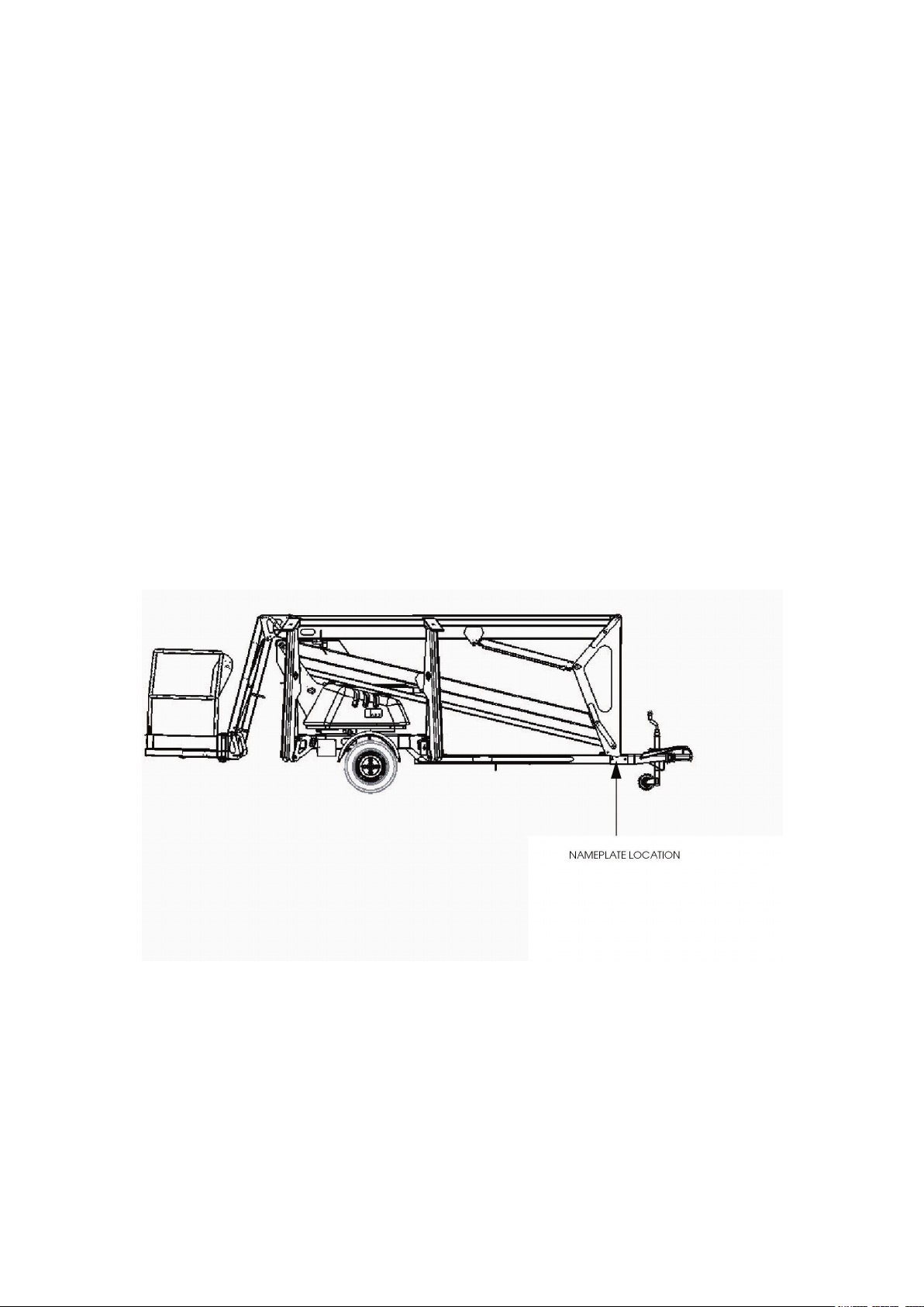
When contacting Snorkel for service orparts information, always include the
MODEL and SERIAL NUMBER from the machine namplate.
The serial number is stmped into
the chassis above the machine
nameplate.
e.g. 7 # # #
www.snorkellifts.com
Page 4

Page 5
WARNING
All personnel shall carefully read, understand and follow all safety rules and operating instructions
before operating or performing maintenance on any Snorkel platform.
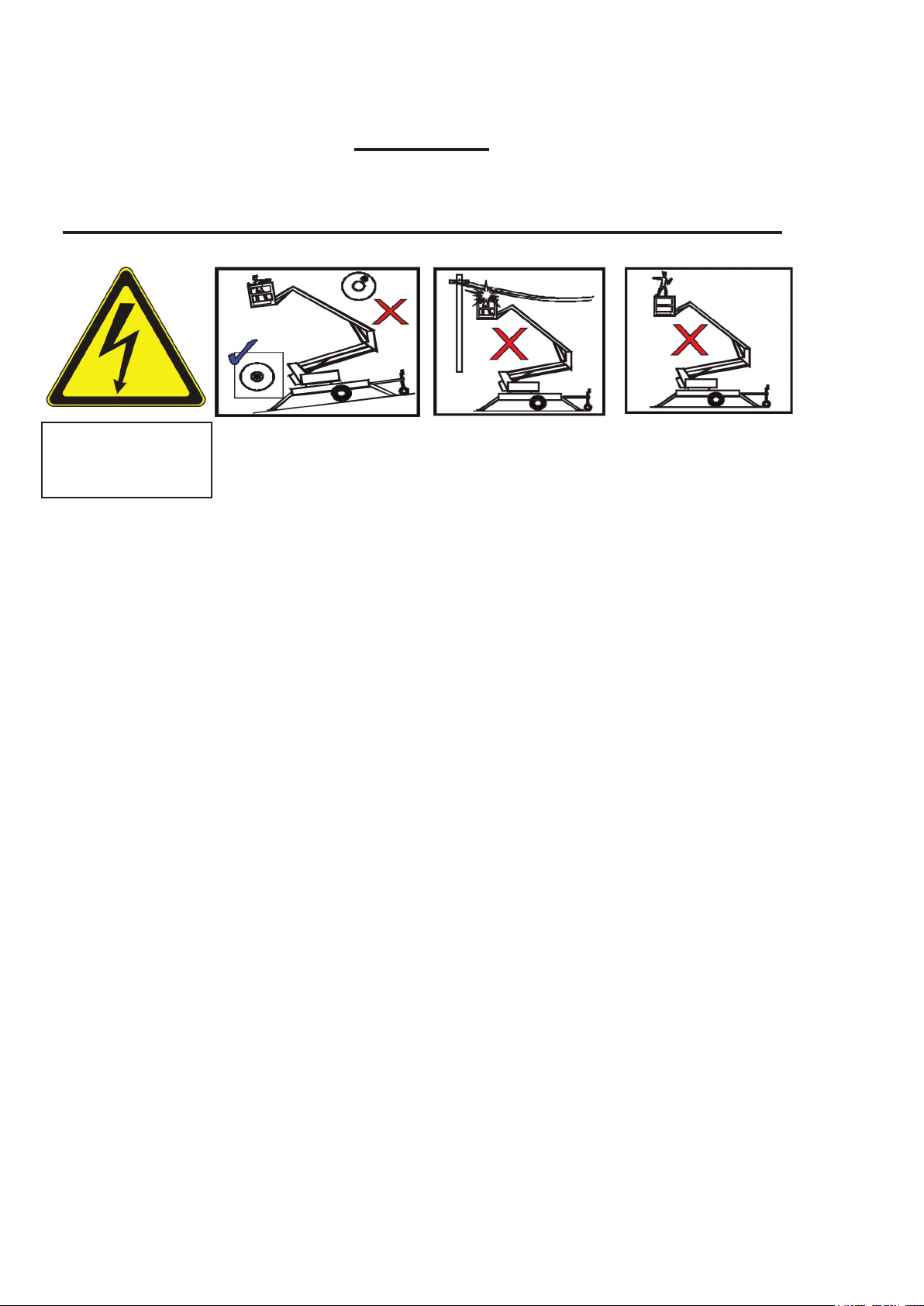
Safety Rules
Electrocution Hazard Tip Over Hazard Collision Hazard Fall Hazard
NEVER climb, stand, or sit
on platform guardrails or
midrail.
THIS MACHINE IS NOT
INSULATED!
NEVER elevate the platform
or move the machine while
elevated. Always level the
machine with the outriggers
before elevating the platform.
NEVER position the platform
without first checking for
overhead obstructions or
other hazards.
Always check the outriggers before entering the platform
USE OF THE AERIAL WORK PLATFORM: This aerial work platform is intended to lift persons and his tools as well as the
material used for the job. It is designed for repair and assembly jobs and assignments at overhead workplaces (ceilings,
cranes, roof structures, buildings etc.). All other uses of the aerial work platform are prohibited!
THIS AERIAL WORK PLATFORM IS NOT INSULATED! For this reason it is imperative to keep a safe distance from live
parts of electrical equipment!
Exceeding the specied permissible maximum load is prohibited! See “Platform Capacity” on page 7 for details.
The use and operation of the aerial work platform as a lifting tool or a crane is prohibited!
NEVER exceed the manual force allowed for this machine. See page 11 for details.
DISTRIBUTE all platform loads evenly on the platform.
NEVER operate the machine without rst surveying the work area for surface hazards such as holes, drop-offs, bumps,
curbs, or debris; and avoiding them.
OPERATE machine only on surfaces capable of supporting wheel loads.
NEVER operate the machine when wind speeds exceed this machine’s wind rating. See “Beaufort Scale” on page 12 for
details.
IN CASE OF EMERGENCY push EMERGENCY STOP switch to deactivate all powered functions.
IF ALARM SOUNDS while platform is elevated, STOP, carefully lower platform. Move machine to a rm, level surface.
Climbing up the railing of the platform, standing on or stepping from the platform onto buildings, steel or prefab concrete
structures, etc., is prohibited!
Dismantling the entry gate or other railing components is prohibited! Always make certain that the entry gate is closed
and securely locked!
It is prohibited to keep the entry gate in an open position when the platform is raised!
To extend the height or the range by placing of ladders, scaffolds or similar devices on the platform is prohibited!
NEVER perform service on machine while platform is elevated without blocking elevating assembly.
INSPECT the machine thoroughly for cracked welds, loose or missing hardware, hydraulic leaks, loose wire connections,
and damaged cables or hoses before using.
VERIFY that all labels are in place and legible before using.
NEVER use a machine that is damaged, not functioning properly, or has damaged or missing labels.
To bypass any safety equipment is prohibited and presents a danger for the persons on the aerial work platform and in
its working range.
NEVER charge batteries near sparks or open ame. Charging batteries emit explosive hydrogen gas.
Modications to the aerial work platform are prohibited or permissible only at the approval by Snorkel.
AFTER USE, secure the work platform from unauthorized use by turning the keyswitch off and removing key.
Page 6

2
CONTENTS
Page
Introduction 4
Description of Equipment 5
Technical Specication 6
Working Envelope 7
Operator Requirements 8
Warning Notices 9
. Beaufort Scale 10
Towing Instructions 11
Pre-Start Checks 13
Batteries, & Power Pack 15
Setting Up 16
Extending Structure 18
. Basket Controls 18
. Ground Controls 19
Safety Harness 20
Emergency Controls
. Emergency Stops 20
. Emergency Lower (Aided) 21
. Emergency Lower (Unaided) 22
. Emergency Slew 22
. Cage Overload 23
. Emergency Battery Isolation 24
Stowing the Machine 25
Page 7

3
CONTENTS
Page
Maintenance
. Daily Checks 26
. Weekly and Monthly Checks 27
. Slew Drive and Limit Switches 28
Trailer lights 29
Appendices
App’1 Petrol/Bi-fuel Option. 30
App’2 Generator Option. 31
App’3 Mains connection. 32
Page 8
4
INTRODUCTION
The Snorkel TL37J’s unique combination of strength, versatility and simplicity, have made it
an instant leader in its class.
Its exceptional working envelope, despite the low towing weight, is achieved thanks to our innovative boom design.
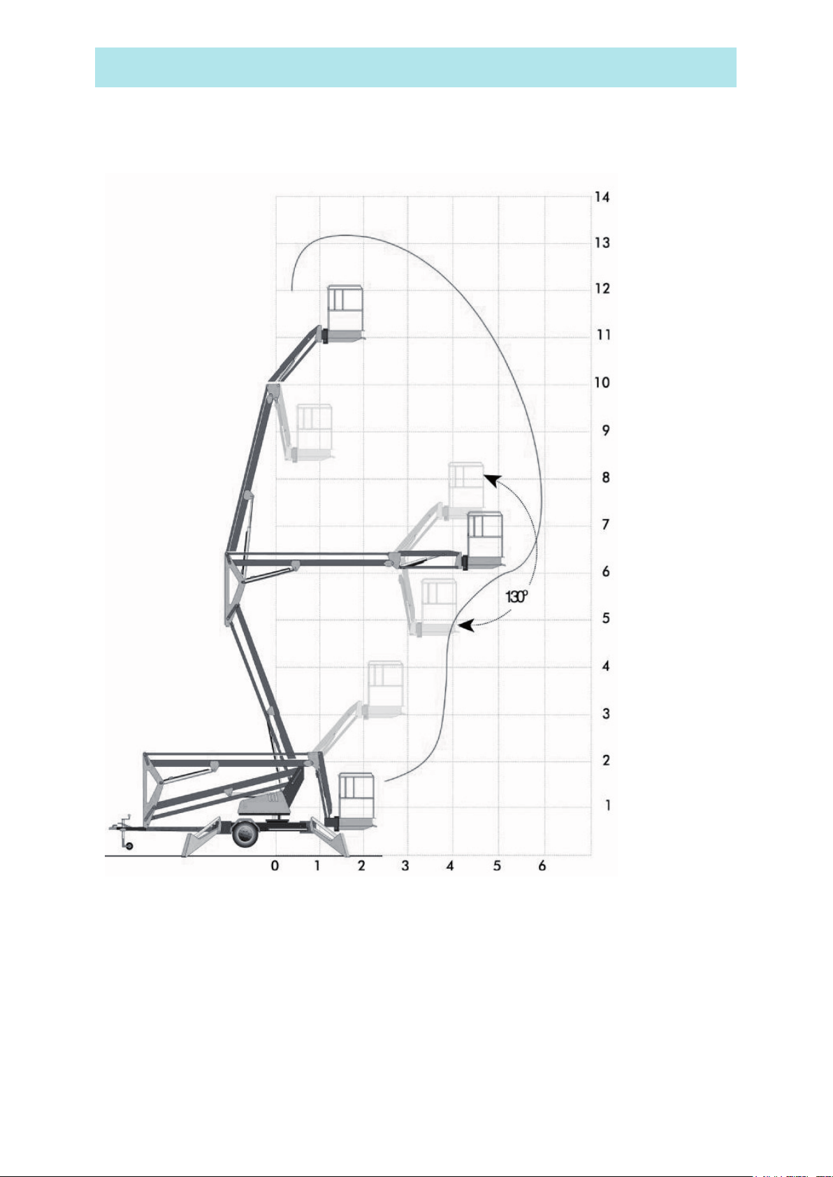
The third ick boom, with 130 DEGREES working arc, guarantees access to the most hard to
reach places, while the 90 DEGREES basket rotation provides the precision positioning that
is vital for working in tight spaces.
Snorkel has a global reputation for innovation and a proud heritage in the design and manufacture of high quality powered equipment.
The company was founded in the UK more than 25 years ago, on the principle of constantly
improving service excellence for end users.
Every model in our growing range of versatile, trailer mounted units is a class leader and together they have set new industry benchmarks.
Our commitment to research and design, plus 250,000sq ft of same site fabrication, build and
support capacity, mean Snorkel can offer complete solutions to meet even the most demanding access applications.
Snorkel has third party accreditation to quality standard ISO 9001 and the full range proudly
carries the CE mark, complying with or exceeding all relevant standards and EC directives.
SNORKEL is a member of the IPAF
International Powered Access Federation.
To ensure you are fully aware of safety and operational information,
the following symbols are used throughout this manual
This type of box contains, Points of operation to NOTE.
The information contained in this type of box contains, WARNING text.
It gives Warnings about the risk of Damage to equipment, and possibly
personnel.
;
The information contained in this type of box contains, DANGER text.
It gives Warnings about the risk of PERSONAL INJURY to the operator
and or others.
Page 9

5
DESCRIPTION OF EQUIPMENT
The Snorkel TL37J is of the parallel linkage vertical boom design, mounted on either a road
towable trailer, or on industrial bogie chassis . The unique yet very simple boom conguration
gives the maximum safety and control ability combined with a robust construction to withstand
a heavy working environment.
The TL37J machine is designed for two man capacity with 215 kg S.W.L.
The machine incorporates a bottom boom with tie rod, a short vertical boom and a top boom
with tie rod. The TL37J has also an independent hydraulically operated Flick-Out Boom and
Rotating Cage for extra manoeuvrability.
The hydraulic system is of a fail-safe design throughout, with built-in hydraulic lock valves
on all the rams as a precaution against hose failure. The machine is controlled by means of
proportional manual lever operated valves. These valves are located at both the base and in
the cage, as standard.
Emergency lower valves are tted as standard to allow the machine to be lowered from the
Base. Additionally, a hand pump is tted in the cage for emergency operation.
The hydraulically operated outriggers are tted with load sensing interlocks, to prevent the booms
being raised without the outriggers being extended and under load. An interlock prevents the
hydraulic outriggers being accidentally retracted while the booms are raised. A simple system of
warning lights show the power is on and each of the outriggers is under load.
Performance.
Maximum Working Height 13.1 m
Maximum Working Outreach 5.9 m
Capacity (2-man working) 215 kg
Slewing Arc 700°
Airborne Noise Emissions (Battery) 70 dB(A)
(Engine) 100 dB(A)
(Diesel) 103 dB(A)
Construction Standards.
The machine complies fully with the requirements of the following EEC Directives:
Directive 98/37/EC, the ‘Machinery Directive’.
Directive 89/336/EEC, as amended – the ‘Electromagnetic Compatibility Directive’.
Directive 73/23/EEC, as amended – the ‘Low Voltage Directive’.
The machine is designed and tested in accordance with all relevant B.S.I. and European
Standards including EN280.
Page 10

6
TECHNICAL SPECIFICATION
Cage Dimensions
Length 1.20m
Width 0.80m
Guard-rail Height 1.10m
Toe-board Height 0.15m
Operating Dimensions
Maximum Working Height 13.10m
Maximum Cage Height 11.10m
Maximum Outreach ( From centre of rotation ) 5.90m
Travel Dimensions
Towing Length 6.43m
Closed Width 1.48m
Closed Height 1.95m
Weight (Battery Model) 1450kg (unladen)
Operating Parameters
Safe Working Load 215 kg
Maximum Horizontal Pull 400 N
Maximum Wind Speed 12.5 ms
Rotation 700°
Cage Slew 90°
-1
Equipment
Bottom Ram Double acting: Bore Ø 60.0 mm
Rod Ø 40.0 mm
Top Ram Double acting: Bore Ø 60.0 mm
Rod Ø 40.0 mm
Flick Ram Double acting: Bore Ø 60.0 mm
Rod Ø 40.0 mm
Stabiliser Ram Double acting: Bore Ø 70.0 mm
Rod Ø 40.0 mm
Bottom & Top Ram Lock Valves Pilot operated over centre valves
Control Valve (Cage) Monoblock unit consisting of ve double acting spools
Control Valve (Ground) Monoblock unit consisting of four double acting
spools
Control Valve (Stabiliser) Monoblock unit consisting of four double acting
spools
Bushes Acetol resin polymer with sintered bronze base (DX)
Pivot Pins Stainless Steel Bright Bar
To Grade BS970 303 S31 CW
Page 11
7
WORKING ENVELOPE
Height in Meters
Reach in Meters
Page 12

8
OPERATOR REQUIREMENTS
1. To operate the machine you must be medically t and have no problems with eyesight or
hearing.
2. You must have a good head for heights.
3. Your primary concern must be the safe operation of the work platform, the safety of the
people working with you, and the safety of other persons in your working area.
4. You must be familiar with the contents of this manual, and at no time attempt to operate
the machine beyond the recommended limits.
5. The proper care of the work platform is a major factor in ensuring the safety of those who
work with it.
6. You must not misuse the machine or ignore or interfere with the devices that have been
provided to maintain safety.
7. Operation of the machine should be restricted to personnel who have been authorised to
operate the equipment and have received proper training.
Page 13

9
WARNING NOTICES
1. DO NOT operate this machine unless you have been fully trained in its safe use.
2. DO NOT operate the machine on soft, slippery or sloping ground unless adequate
precautions have been taken.
The stabilisers are designed to operate on rm level ground with a minimum bearing
2
strength of 50N/cm
.
The maximum load imposed by an outrigger is 10.3kN.
Advice should be obtained from Snorkel as to the type of supports and precautions
required before attempting to operate the machine outside these parameters.
3. DO NOT use any equipment in the basket to increase the reach or working height of the
machine, e.g. ladders.
4. DO NOT t any additional equipment to the machine that would increase the wind
loading, e.g. notice boards.
5. DO NOT use the machine for any application that may produce special loads or forces:
the manufacturer, Snorkel, must be consulted for approval of special applications prior
to use.
6. DO NOT use the
machine close to live
electrical conductors.
The minimum safe
working distance for
a machine working
near overhead power
15m
cables is the maximum
extended length of the
booms plus 15 metres,
measured with the
booms pointing towards
the lines, i.e. safe
working distance for
the TL37J is 20 metres.
It is the operator‘s
20m
responsibility to ensure
that, when working in
the vicinity of live overhead high-voltage lines, the minimum safe working distance is
maintained. Erect a simple barrier tape at the safe distance.
7. WORKING CLOSE TO POWER CABLES – if work has to be carried out at less than
the safe working distance, the operator must ensure that the electricity supply
has been switched off. Before commencing work, a written permit to work must be
obtained from the owners of the power cables or the responsible authority.
Page 14

10
WARNING NOTICES
8. DO NOT operate the machine unless all four outriggers are down and in full contact
with the ground. The machine must be level and the wheels lifted visibly clear of the
surface before the booms are raised.
9. DO NOT move the machine with the
basket raised and never allow cage or
booms to slew into the path of oncoming
vehicles.
10. DO NOT operate the machine if the wind speed exceeds 12.5 m/s. Be aware that,
when working near high buildings or structures, shielding and funnelling effects may
cause high wind forces on days when the nominal wind speed in the open is low. Wind
speed can either be measured from the work platform with a hand held anemometer or
estimated using the Beaufort Scale.
BEAUFORT WIND SPEED SCALE
The Beaufort Scale of wind force is accepted internationally and is used in communicating
weather conditions. It consists of numbers 0 - 12, each representing a certain strength of
velocity of wind at 10m (33ft.) above ground in the open.
Numbers 10-12are not shown in this table.
DESCRIPTION OF WIND SPECIFICATION FOR USE ON LAND M/Sec
0 CALM
1 LIGHT AIR
2 LIGHT BREEZE
3 GENTLE BREEZE
MODERATE
4
BREEZE
5 FRESH BREEZE
6 STRONG BREEZE
7 NEAR GALE
8 GALE
9 STRONG GALE
Calm – smoke rises vertically
Direction of wind shown by smoke drift but not by wind
vanes.
Wind felt on faces; leaves rustle; ordinary vanes moved by
wind.
Leaves and small twigs in constant motion; wind extends
light ag.
Raises dust and loose paper; small branches are moved.
Small trees in leaf begin to sway; crested wavelets form on
inland waterways.
Large branches in motion; umbrellas used with difculty.
Whole trees in motion; inconvenience felt when walking
against wind.
Breaks twigs off trees; generally impedes progress.
Slight structural damage occurs (chimney pots and slates
removed)
0-0.5
0.6-1.5
1.6-3.0
3.5-5
6-8
9-10
11-13
14-17
18-21
22-24
Approximate corrections for wind speeds at other heights are:
2m subtract 30%; 3m subtract 20%; 6m subtract 10%
15m add 10%; 30m add 25%
Page 15

11
TOWING INSTRUCTIONS
Trailer mounted machines are tted with suspension units that may be safely towed
behind a car or van at speeds of up 50mph (80km/h) where permitted.
1. Before towing, check the capacity of the vehicle being used.
(Machine weight will increase if optional extras are tted)
2. Ensure that the road tyres and brakes are in good, serviceable condition.
3. Ensure that all booms are fully lowered and both the transit pins are tted through the
transit pin holes and secured with the “R” clip on the end of the chain. (see photographs
below)
Page 16

12
TOWING INSTRUCTIONS
4. Ensure that all outriggers are fully raised.
5. Use the Jockey Wheel to raise or lower the tow bar coupling to position the machine
above the 50mm ball hitch on the towing vehicle.
6. Apply the handbrake.
7. Lower the tow bar coupling down onto the ball hitch using the Jockey Wheel
8. Secure the breakaway cable, (Ensure correct engagement of 50mm ball).
9. Fully raise the Jockey Wheel and lock in position.
10. Release the Handbrake.
11. Plug in the trailer lights (7 pin plug) and check that both vehicle and trailer lights are
working correctly.
Page 17

13
PRE-START CHECKS
The following Pre-Start Checks should be carried out before taking the machine to the
place of work.
1. Damaged or Loose Fittings.
Visually Inspect the machine for signs of wear and tear, damage, loose or missing parts.
2. Wheels. (For towing only)
Check tyres are at the correct pressure, 55 psi (3.8 bar) and that the wheel nuts are
tightened using the correct torque setting (100Nm).
3. Hydraulic uid.
The hydraulic oil tank is located underneath the slew cover on the left hand side of the
machine (looking from the cage end).
With the booms and outriggers in the transport position, the hydraulic oil level should be
visible between the upper and lower marks of the dipstick.
Do Not Overll the Hydraulic Tank
Serious injury or even death may result by not carrying out the
following checks of the interlock system before the platform is
used!
Top up with ISO Grade 22 hydraulic oil if necessary.
4. Safety Switches.
Visually check the cage overload switch is free from damage.
Check all limit switch arms are free from damage and move easily .
With outriggers in transport position, it must not be possible to operate the extending
structure.
With outriggers deployed, under load and top or bottom boom raised approximately
50mm, it must NOT be possible to operate the outrigger controls.
The ick boom is not interlocked with the outriggers.
5. Emergency Stop Switches.
Emergency stop switches must operate correctly. Check that each stops the machine’s
controls and that restarting is prevented until all stop switches are unlatched.
Page 18

14
PRE-START CHECKS
6. Emergency Lower/Slew.
With the top and bottom booms raised approximately 500mm each and the unit switched
off, check:
The emergency slew can be operated with the slew handle provided.
The emergency lower valves located on the lift cylinders lower the boom when pushed in
a slow and controlled manner and that the boom movement is stopped on releasing the
valve
To Reset the hydraulic system after checks;
□ Fully slew the Basket to the right, so that he ram is fully extended.
Fully extend the Outriggers while still maintaining Level. (check the bubble) □
Using the ground controls, fully extend both Top and Bottom Booms. □
Fully extend the Flick Out Boom □ .
All rams must be fully extended at the same time before returning them to their transit
position.
7. Emergency Hand Pump.
With the unit set up for working (i.e. outriggers down, under load and the machine level
with wheels clear of ground) it is possible to lower the cage using the emergency hand
pump.
If the Emergency Lower is used during normal operation, DO NOT use the
machine, Contact your local Snorkel representative.
8. Battery Power (Where applicable)
Check batteries are fully charged and topped up with distilled water (these.are tted
under the slew cover on both sides of the platform) and that the Battery Isolating Plug is
securely connected.
Hydrometer reading should be 1280-1320sg.
With machine level, the distilled water should cover the plates by approximately 6mm.
9. Mains Power (Where applicable)
Connect the mains supply, either 110V or 220/240V A.C., depending upon the motor
specication. Check the motor is running when the key is turned to the ON position.
Check that the voltage and frequency of the power input matches that of the motor. All
extensions must be a minimum of 2.5mm², and no longer than 10m due to possible
voltage drop.
10. Petrol Power (Where applicable)
Check the fuel and oil levels of the engine. Switch on the ignition using the key switch on
the slew mounted legend panel. Check the engine runs using the start and stop buttons
in the basket. Check that there is sufcient oil and fuel to complete a full working shift.
Page 19

15
BATTERIES & POWER PACK
Battery Charger
Fig. 1
Batteries
Dipstick
Fig. 2
Oil Filler
All extensions must be a minimum of 2.5mm², and no longer than 10m,
due to possible voltage drop, which will damage the motor.
Page 20

16
SETTING UP
1. Park the unit in an appropriate location at the workplace.
2. Apply the handbrake on the trailer and remove from the towing vehicle.
Do not attempt to set up the machine on steep slopes, ramps or soft
ground.
3. With platform key switch set to ’Ground’ (Fig 3)
OFF
Basket
lower the outriggers by keeping the ‘Outrigger
Motor Run’ button (Fig 5) pushed in, operate the
appropriate ‘Outrigger control lever’ (Fig 4), until
all four are 25mm to 50mm from the ground.
Ground
Fig. 3
Control Levers
Ground
Level
indicator
Control Levers
Outriggers
4. Lower the Outriggers two at a time starting at the tow bar end (No’s 3&4) until the jockey
wheel just clears the ground.
5. Lower Outriggers 1&2 until the green LED display indicates that they are under load.
(Fig 6)
6. Repeat this sequence for Outriggers 3&4.
Fig. 4
Take EXTREME care NOT to ground either the Basket, or the Jockey
Wheel during the next step.
Page 21

17
SETTING UP
Control
Selector
Emergency
Stop
Outrigger Load
Motor Run
Outriggers
Indicators
Cage Overload
Indicator
Motor Run
Booms
Fig. 5
7. By alternating from 1&2 to
3&4, carefully inch down each
pair of Outriggers until all four
Outriggers are fully deployed,
and the wheels are well clear of
the ground.
8. Now, by using the Level
indicator (Fig.4), raise opposite
Fig. 6
Outriggers until the bubble and
indicator ring are concentric
(i.e., the bubble rests in the
centre).
9. Check that each LED on the Ground Control panel is still illuminated. This indicates that
each foot is in rm contact with the supporting surface.
The unit is designed to operate on a supporting surface of minimum
2
bearing strength of 50N/cm
.
The maximum outrigger load is 10.3kN.
Page 22

18
EXTENDING STRUCTURE
The SET-UP section of this manual MUST be completed before extending
the structure.
1. Remove and correctly stow the Transit Pins, from both the Upper and Lower Booms.
2. At the Ground Control Station, turn the key to ‘Basket’ (See point #6.)
3. Climb into the basket. Check that
all Emergency Stop Switches
are released (twisting release).
The platform may now be raised,
lowered or slewed in any direction
by operating the control levers at the
basket, whilst depressing the motor
run button (DEADMAN).
4. Explanation of the Basket Control Station, Directional Control Levers
Raise
Lower
Slew
Turret
Raise
Upper
Raise
Flick
Slew
Basket
Lower
Lower
Slew
Turret
Lower
Upper
Lower
Flick
Slew
Basket
Page 23

19
EXTENDING STRUCTURE
5. A duplicate set of controls (excluding Slew Basket) is mounted on the Slew Turret under
the right hand side cover, which allows the platform to be operated from the Ground.
6. At the Ground Control Station, turn the key to ‘Ground’.
Basket
Ground
7. Explanation of the Ground Control Station, Directional Control Levers
Raise
Lower
Boom
Lower
Lower
Boom
Slew Turret
Anticlockwise
Slew
Turret
Clockwise
Raise
Upper
Boom
Lower
Upper
Boom
Raise
Flick
Boom
Lower
Flick Boom
Take EXTREME care when slewing both basket and turret, at low
levels.
Before raising, ensure there are no overhead obstructions or power
cables and the outriggers are properly extended and secure.
Page 24

20
SAFETY HARNESS & EMERGENCY CONTROLS
1. In accordance with IPAF recommendations, Snorkel recommend the use of a Full Body
Harness with an adjustable lanyard is used when operation from the basket.
2. The lanyard length should be as short as possible.
3. A permanent anchoring attachment point is provided in the basket for xing the harness.
EMERGENCY CONTROLS
1. Emergency Stop
Emergency Stop buttons are tted on the machine to stop the motor in an emergency.
There are 2 Emergency Stop Buttons, one in the basket, and one on the ground control
panel.
The emergency stops are ‘Reset’ by twisting.
Page 25

21
EMERGENCY CONTROLS
2. Emergency Lower.
In the event of a power failure, There are two ways of Safely lowering the basket.
Emergency Lowering, method one
If you are able to get assistance from the ground they can lower both booms by pressing
the Emergency Lower Valve on the ram.
Open the Lower Ram valve rst to facilitate access to the Top Ram valve.
Each emergency lower valve will automatically close when the handle
is released.
If the Emergency Lower is used due to a machine defect, DO NOT use the
machine, Contact your local Snorkel representative.
If the Emergency Lower is used, The TOP and BOTTOM BOOMS must be
fully extended then fully lowered before work can continue.
After Emergency lowering, any further POWERED lowering could cause
an AIRLOCK in the hydraulic system.
This could cause the Hydraulic operations to Fail.
ALL BOOMS MUST BE FULLY EXTENDED/RAISED, THEN LOWERED
BEFORE WORK CAN RECOMMENCE.
Page 26

22
EMERGENCY CONTROLS
Emergency Lowering, method two.
You can operate the hand pump in the cage and operate the lowering boom
functions.
To operate the hand pump, simply insert the lever into the pump shaft, move a
control lever to the required direction of movement, and operate the hand pump.
When the machine starts to lower, continue depressing the control lever.
3. EMERGENCY SLEW.
In the event of a power failure, the machine may be manually slewed by moving the base
control slew lever in the desired direction and manually indexing the Slew Platform by
means of ratchet on the shaft of the Slew Gearbox.
Vigorous pumping is required to lower and operate the slew.
Page 27

23
EMERGENCY CONTROLS
4. CAGE OVERLOAD.
In the event of the cage being overloaded, an audible alarm will sound and the cage
controls will cut out.
To re-start, enough load must be removed from the cage so that the alarm stops
sounding.
In cases where the overload can not be immediatley removed or the cage has fouled,
then the overload override selector switch can be used to move the platform to a safe
position so that the overload can safely removed.
The Key, Motor Run/Deadman and a Control Lever must be
operated at the same time to effect this action
Page 28

24
EMERGENCY CONTROLS
4. EMERGENCY BATTERY ISOLATING PLUG
Disconnecting this plug will isolate the batteries from the powerpack and operating
circuits.
Before operating this machine, it is important that both the Operator
and another responsible person on site, is aware of the position and
function of the following:
A) Emergency Stop Buttons.
B) Emergency Lowering Buttons.
C) Emergency Slew Drive Shaft.
D) Battery Isolating Plug.
Page 29

25
STOWING THE MACHINE
1. Fully lower all the booms.
2. Engage the Transit Pins, and lock in place using ‘R’ clip.
3. With platform keyswitch set to ‘Ground’:
Raise the outriggers by simultaneously depressing the ‘MOTOR RUN Outrigger’
button and using the appropriate control levers, two at a time, alternating between the
cage and tow bar end until the road wheels are in contact with the ground.
Only when the road wheels are in contact with the ground should the unit be lowered
further until the jockey wheel makes contact with the supporting surface.
Now fully raise the outriggers until they are in the stowed position.
Switch off the platform and ensure all loose items/covers are secure before towing the
unit.
The machine is now ready for transportation.
TRANSPORT PIN LOCATIONS – SHOWN READY FOR TRANSPORT
Lower
Boom
Upper
Boom
Page 30

26
MAINTENANCE
The unit must have a thorough inspection carried out every 6 months
in accordance with LOLER Regulations 1998 and a Certicate of
Thorough Inspection produced by a competent person.
Always ensure the machine structure is in good, sound, undamaged
condition. Any inspection procedure is always aided by keeping the
machine clean.
NB. Do not steam clean the battery charger or electrical
components.
Daily Checks.
1. Damaged or Loose Fittings.
Visually Inspect the machine for signs of wear and tear, damage, loose or missing
parts.
2. Wheels.
Check tyres are at the correct pressure, 55 psi (3.8 bar) and that the wheel nuts
are tightened using the correct torque setting (100Nm).
3. Hydraulic uid.
The hydraulic oil tank is located underneath the slew cover on the left hand side of the
machine (looking from the cage end) .With the booms and outriggers in the transport
position, the hydraulic oil level should be visible between the upper and lower marks of
the dipstick.
Top up with ISO Grade 22 hydraulic oil if necessary.
Do Not Overll the Tank
4. Safety Switches.
Check all limit switch arms are free from damage and move easily.
With outriggers in transport position, it must not be possible to operate the extending
structure.
With outriggers deployed, under load and top or bottom boom raised approximately
50mm, it must NOT be possible to operate the outrigger controls.
The ick boom is not interlocked with the outriggers.
5. Emergency Stop Switches.
Emergency stop switches must operate correctly. Check that each stops the machine’s
controls and that restarting is prevented until all stop switches are unlatched.
Page 31

27
The unit must have a thorough inspection carried out every 6 months
in accordance with LOLER Regulations 1998 and a Certicate of
Thorough Inspection produced by a competent person.
Always ensure the machine structure is in good, sound, undamaged
condition. Any inspection procedure is always aided by keeping the
machine clean.
NB. Do not steam clean the battery charger or electrical
components.
Weekly Checks.
MAINTENANCE
Slew Drive
1. Apply grease to the slew gear wheel and all grease nipples.
2. Check battery acid level, top up with distilled water if required (maximum 6mm over
plates when battery is standing level), and check mains cable wiring.
Monthly Checks.
1. Thorough machine inspection to be carried out by a trained and competent person.
(LOLER)
FOR ENGINE MAINTENANCE REFER TO MANUFACTURES GUIDELINES
Page 32

28
MAINTENANCE
Slew Drive Gears.
The slew drive gear is designed to be largely maintenance free. However, we recommend the
gear teeth be greased on a monthly basis with a high pressure grease. Additionally, the ring
gear and gear box should be greased on a six monthly basis. The grease nipple for the ring gear
is on the top face of the slew gear, set between the xing bolts. It can be accessed by lifting one
of the side covers, and slewing the structure appropriately.
Grease
Nipple
The ring gear should be inspected on a six monthly basis for excessive play. It is unlikely there
will be any wear if the machine is maintained correctly.
Grease
Nipples
To check the gear, place a payload of approximately 80Kg in the platform. Elevate the lower
boom to approximately half way. Then gently elevate the top boom, whilst observing the ring
gear. Excessive wear will be observed by noticing more than 0.5mm movement between the
inner and outer bearing rings.
Checking Limit Switch Operation.
The limit switches require no maintenance, other than a visual inspection, on a pre operation
basis. This is an important check, to ensure the switch is not mechanically damaged, and
the roller is always in contact with the cam, when not under load.
The switch operation can be simply checked, by observing the LED display when deploying the
stabilizers. As an outrigger foot touches the ground and becomes loaded, the appropriate light
will change to green. This indicates that the switch contact has operated correctly
Outriggers
under load
Outriggers NOT
under load
If the LED displays green at any other time then the machine must not be operated, until the
fault is rectied.
Page 33

29
7 PIN PLUG INTERIOR VIEW
YELLOW
RED
BLACK
BLUE
MAINTENANCE
WHITE
YELLOW
RED
WHITE
BROWN
BLACK
GREEN
GREEN
BROWN
RED
WHITE
BLUE
L.H. Flasher
STOP/
TAIL
FOG Light
No. Plate
Light
No. Plate
Light
FOG Light
STOP/
TAIL
R.H. Flasher
Pin No Ref. Colour Function
1 L YELLOW L.H.INDICATOR
2 54G BLUE FOG LIGHT(S)
3 31 WHITE EARTH
4 R GREEN R.H. INDICATOR
5 58R BROWN R.H. TAIL & No. PLATE
6 54 RED STOP LIGHT
7 58L BLACK L.H. TAIL & No. PLATE
.
Page 34

30
Appendix 1
Bi Fuel Option
This machine variant is tted with a petrol
engine, with remote start and stop.
This manual does not cover the maintenance of
the engine.
For engine maintenance details refer to the
engine manufacturers handbook.
Prior to operating the engine, follow these simple guidelines;
a) ensure there is adequate fuel for the task in hand
b) check the oil level prior to starting the generator
c) Check battery electrolyte level. (Where applicable, Lead Acid batteries Only)
1. To use the engine, simply switch the fuel on, with the lever.
2. With the key, turn the ignition to start, motor on, releasing
the starter when the engine res.
3. Or, if using the basket controls turn the key to engine
and push the start button.
4. With the engine running, It will now be possible to operate the machine Hydraulic controls
as long as there is power in the main batteries.
Page 35

31
Generator option
This machine variant is tted with a 2.2 kva
generator, with remote start and stop.
This manual does not cover the maintenance of the
generator.
For maintenance details refer to the manufacturers
handbook.
Prior to operating the generator, follow these simple guidelines;
a) ensure there is adequate fuel for the task in hand
b) warm the engine prior to switching off at the platform.
c) check the oil level prior to starting the generator
Appendix 2
1. To use the generator, simply switch the fuel on, with the
lever.
2. With the key, turn the ignition to start, motor on, releasing
the starter when the engine res.
3. Ensure the voltage output matches the appliance intended for use.
4. Connect the ying plug.
5. With the engine running, power will automatically be supplied to the battery charger,
and the platform socket. It is possible to operate the machine lift controls with the
battery charger switched on.
Page 36

Appendix 3
Mains connection
This machine variant requires a power supply from a xed source.
Prior to operating the machine, follow these simple guidelines;
a) Ensure the power supply being attached is the correct voltage.
b) Ensure the power supply being used is being supplied via an appropriate power
extension.
All extensions must be a minimum of 2.5mm², and no longer than
10m, due to possible voltage drop, which will damage the motor.
1. To connect to a mains supply, simply remove the socket’s protection cap.
2. Connect an appropriately rated power extension.
3. Ensure the voltage output matches the appliance intended for use.
Blue sockets is 240V output. Yellow sockets is 110V output.
4. Ensure that the connection is secure before use.
32
Page 37

Page 38

Local Distributor / Lokaler Vertiebshändler / Distributeur local
El Distribuidor local / ll Distributore locale
EUROPE, MIDDLE EAST
AFRICA & ASIA
PHONE: +44 (0) 845 1550 057
FAX: +44 (0) 845 1557 756
NORTH & SOUTH AMERICA
PHONE: +1 785 989 3000
TOLL FREE: +1 800 225 0317
FAX: +1 785 989 3070
AUSTRALIA
PHONE: +61 2 9725 4000
FAX: +61 2 9609 3057
NEW ZEALAND
PHONE: +64 6 3689 168
FAX: +64 6 3689 164
 Loading...