

Page 1
POWERED ACCESS
Operator Manual
This sectionof theOperatormanualisthe English l version.anguage
TL34
(EN) Manualpart number 510309-000 for serial numbers 00001 tocurrent.
JUL 09
Page 2

Page 3
Operation M
ANUAL
TL34
This manual covers Serial Numbers to Current
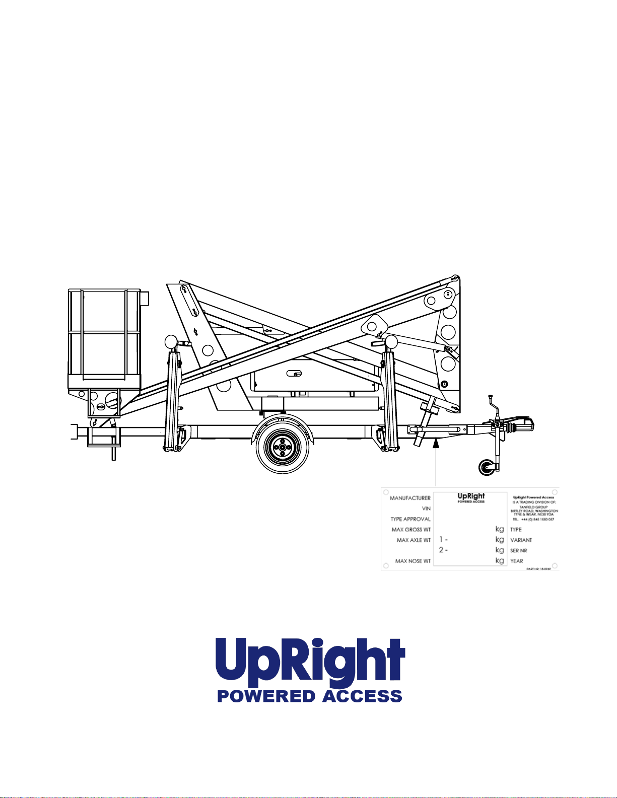
When contacting UpRight Powered Access for service orparts information, always
include the
The serial number is stDmped into the
chassis above the machine nameplate.
e.g. 7 # # #
MODEL and SERIAL NUMBER from the machine namplate.
www.upright.com
Page 4

Page 5
Page 6

CONTENT SECTION
Introduction 1
Description of Equipment 2
Technical Specification 3
Working Envelope 4
Operator Requirements 5
Warning Notices 6-7
Towing Instructions
Pre-Start Checks
Batteries, & Power Pack 11
Setting Up 12-14
Extending Structure 15
Lowering Structure 16
Slewing Structure 17
Safety Harness &
Stowing the Machine 22
Maintenance 23-26
Emergency Controls
8
9-10
18-21
Page 7
INTRODUCTION
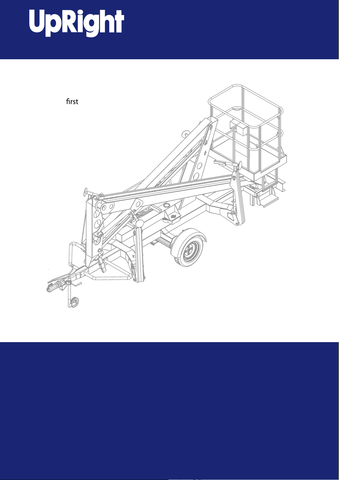
The Aerial Access TL34 is a very versatile means of gaining access in difficult locations.
The machine is extremely safe in operation providing that basic rules are observed in
setting up the machine.
Operators should have read and understood the contents of the manual, and received full
training in the safe use of the machine before attempting to use it.
UpRight has a global reputation for innovation and a proud heritage in the
design and manufacture of high quality powered equipment.
The company
constantly improving service excellence for end users.
Every model in our growing range of versatile, trailer mounted units is a class
leader and together they have set new industry benchmarks.
Our commitment to research and design, plus 250,000sq ft of same site
fabrication, build and support capacity, mean UpRight can offer complete solutions to meet even the most demanding access applications.
UpRight has third party accreditation to quality standard ISO 9001 and the full
range proudly carries the CE mark, complying with or exceeding all relevant standards and EC directives.
was founded in the UK more than 25 years ago, on the principle of
UpRight Powered Access is a member of the IPAF
International Powered Access Federation.
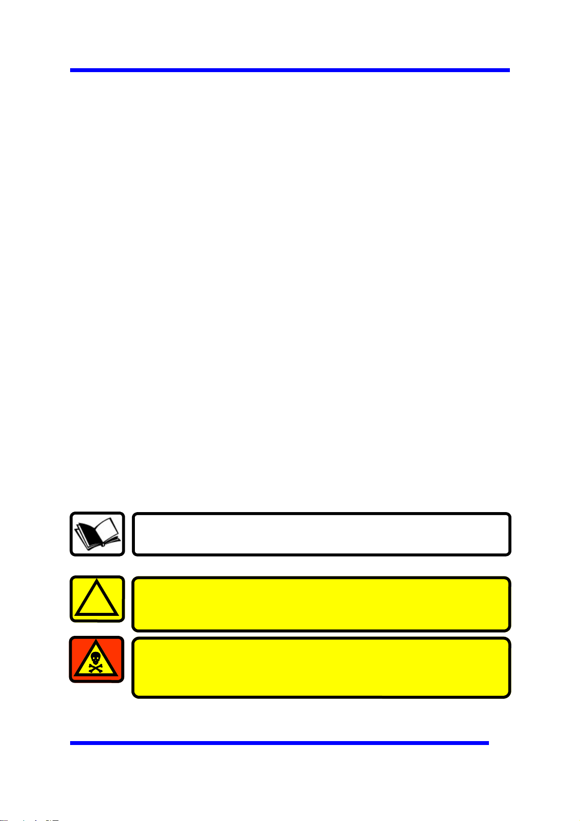
To ensure you are fully aware of safety and operational
information, the following symbols are used throughout this
manual;
!
This type of box contains, Points of operation to NOTE.
The information contained in this type of box contains, WARNING
text. It gives Warnings about the risk of Damage to equipment,
and possibly personnel.
The information contained in this type of box contains, DANGER
text. It gives Warnings about the risk of PERSONAL INJURY to the
operator and or others.
1
Page 8

DESCRIPTION OF EQUIPMENT
The
TL34
is a trailer mounted work platform with a 2-man cage giving access to maximum
height of 12.20m. It offers safe, versatile and easy access for two men plus tools up to a
total of 215Kg. Its unique boom configuration allows this height to be reached while still
offering compact closed dimensions and exceptional manoeuvrability. It is manufactured
from steel hollow sections conforming to BS4360 1986. All joints are fully welded by
Metal Inert Gas (MIG) or Manual Metal Arc (MMA) processes. The main pivots are set in
bushed housings. The bushes are self-lubricating for minimum maintenance and long
life. The main boom pins are chromed and all other pins are Tuftridge
The platform is powered by a 12V DC battery pack operating an electric motor which
in turn drives a hydraulic pump. This provides a maximum hydraulic pressure output
of 210 Bar max. Battery powered models are fitted with an ‘on-board’ battery charger.
Limit switches are fitted to the stabilisers thereby ensuring that the booms cannot be
elevated unless the stabilisers are first deployed. Machines equipped with hydraulic
stabilisers are also fitted with a limit switch on the booms to ensure that the stabilisers
cannot be operated when the booms are elevated. Lift is provided by single acting
hydraulic cylinders on the top and bottom boom and rotation is achieved by the use of a
hydraulic motor driving a pinion via a gearbox.
TH
coated.
Control is provided by a live hydraulic system. Lift is controlled from monoblock bank
valves, mounted in the cage and in the control cabinet at the ground, which allows
precise control of the two platform functions (Lift and Rotate). The lift cylinders are fitted
with solenoid operated check valves which ensure that in the event of hose failure, the
platform will not descent without deliberate action being taken to lower the platform. The
lift cylinders are also fitted with a flow control valve to control the rate at which the
platform descends.
All equipment at ground level except the rotation motor is situated on the cabinet on the
side of the platform.
Facility is provided for lowering the platform at ground level in the case of any emergency
Performance.
Maximum Working Height 12.20 m
Maximum Working Outreach: 5.00 m
Capacity (2 man working): 215 kg
Slewing Arc: 360 degrees°
Airborne Noise Emissions: 70 dB(A)
European Directives.
1) 2006/42/EC – the Machinery Directive.
2) 2004/108/EC – the Electromagnetic Compatibility Directive.
3) 2006/95/EC – the Low Voltage Directive.
The machine is designed and tested in accordance with European Standard EN280.
2
Page 9

TECHNICAL SPECIFICATION
Operating Dimensions
Maximum Working Height 12.20 m
Maximum Cage Height 10.20 m
Maximum Outreach 5.00 m
Outrigger Footprint (manual) 3.6 m x 3.6 m
Outrigger Footprint (hydraulic) 3.7 m x 3.7 m
Cage Dimensions
Length 1.20 m
Width 0.80 m
Guard-rail Height 1.10 m
Toe-board Height 0.15 m
Travel Dimensions
Towing Length 5.30 m
Closed Width 1.5 m
Closed Height 2.2 m
Weight (manual outriggers) 1300 kg
Operating Parameters
Safe Working Load 215 kg
Maximum Horizontal Pull 400 N
Maximum Wind Speed 12.5 ms
Rotation 360 °
Maximum Chassis Inclination 0.5 °
Vibration Less than 2.5ms
Operating Temperature Range -20°c to +40°c
BUSHES Acetol resin polymer with sintered
bronze base (DX)
PIVOT PINS EN 3B high tensile steel
TYRES 165 X 13 8ply
TYRE PRESSURE 3.8 Bar (55psi) cold
WHEEL NUTS TORQUE SETTING 100Nm (75Lbft)
BATTERIES 2 X 6v 225Ah (Heavy duty traction)
-1
-2
CHARGER 12vdc 25a – 110 OR 220Vac 50Hz
3
Page 10

WORKING ENVELOPE
13m
12m
11m
10m
9m
8m
7m
5m 4m 3m 2m 1m 0m 1m 2m 3m 5m
4m
13m
12m
11m
10m
9m
8m
7m
6m
5m
4m
3m
2m
1m
0m
6m
5m
4m
3m
2m
1m
0m
0m5m 5m1m2m3m4m 1m 2m 3m 4m
4
Page 11

OPERATOR REQUIREMENTS
5
1. To operate the machine you must be medically fit and have no problems
with eyesight or hearing.
2. You must have a good head for heights.
3. Your primary concern must be the safe operation of the work platform, the
safety of the people working with you, and the safety of other persons in
your working area.
4. You must be familiar with the contents of this manual, and at no time
attempt to operate the machine beyond the recommended limits.
5. The proper care of the work platform is a major factor in ensuring the safety
of those who work with it.
6. You must not misuse the machine or ignore or interfere with the devices
that have been provided to maintain safety.
7. Operation of the machine should be restricted to personnel who have been
authorised to operate the equipment and have received proper training.
Page 12

WARNING NOTICES
1. DO NOT operate this machine unless you have been fully trained in its safe
use.
2. DO NOT operate the machine on soft, slippery or sloping ground unless
adequate precautions have been taken.
The stabilisers are designed to operate on firm level ground with a minimum
bearing strength of 50N/cm
The maximum load imposed by an outrigger is 10.3kN.
Advice should be obtained from UpRight as to the type of supports and
precautions required before attempting to operate the machine outside
these parameters.
3. DO NOT use any equipment in the basket to increase the reach or working
height of the machine, e.g. ladders.
4. DO NOT fit any additional equipment to the machine that would increase
the wind loading, e.g. notice boards.
5. DO NOT use the machine for any application that may produce special loads
or forces: the manufacturer, UpRight, must be consulted for approval of
special applications prior to use.
6. DO NOT use the
machine close to
live electrical
conductors. The
minimum safe
working distance
for a machine
working near
overhead power
cables is the
maximum
extended length of
the booms plus 15
metres, measured
with the booms
pointing towards
the lines, i.e. safe
working distance for the TL34 is 20 metres. It is the operator‘s responsibility
to ensure that, when working in the vicinity of live overhead high-voltage
lines, the minimum safe working distance is maintained. Erect a simple
barrier tape at the safe distance.
2
.
15m
15m
20m
26m
7. WORKING CLOSE TO POWER CABLES – if work has to be carried out at less
than the safe working distance, the operator must ensure that the
electricity supply has been switched off. Before commencing work, a
written permit to work must be obtained from the owners of the power
cables or the responsible authority.
6
Page 13

WARNING NOTICES
8. DO NOT operate the machine unless all four outriggers are down and in full
contact with the ground. The machine must be level and the wheels lifted
visibly clear of the surface before the booms are raised.
9. DO NOT move the machine with the
basket raised and never allow cage
or booms to slew into the path of
oncoming vehicles.
10. DO NOT operate the machine if the wind speed exceeds 12.5 m/s. Be aware
that, when working near high buildings or structures, shielding and
funnelling effects may cause high wind forces on days when the nominal
wind speed in the open is low. Wind speed can either be measured from
the work platform with a hand held anemometer or estimated using the
Beaufort Scale.
BEAUFORT WIND SPEED SCALE
The BeaufortScale ofwind force is accepted internationally and is usedin communicating
weather conditions. It consists of numbers0 -12,each representing a certain strength of
velocity of windat 10m (33ft.) above ground in the open.
Numbers 10-12are not shown in this table.
DESCRIPTION OF WIND
0 CALM
1 LIGHT AIR
2 LIGHT BREEZE
3 GENTLE BREEZE
4 MODERATE BREEZE
5 FRESH BREEZE
6 STRONG BREEZE
7 NEAR GALE
SPECIFICATION FOR USE ON LAND M/Sec
Calm – smoke rises vertically
Direction of wind shown by smoke drift but not by wind vanes.
Wind felt on faces; leaves rustle; ordinary vanes moved by wind.
Leaves and small twigs in constant motion; wind extends light
flag.
Raises dust and loose paper; small branches are moved.
Small trees in leaf begin to sway; crested wavelets form on inland
waterways.
Large branches in motion; umbrellas used with difficulty.
Whole trees in motion; inconvenience felt when walking against
wind.
0-0.5
0.6-1.5
1.6-3.0
3.5-5
6-8
9-10
11-13
14-17
8 GALE
9 STRONG GALE
Approximate corrections for wind speeds at other heights are:
2m subtract 30%; 3m subtract 20%; 6m subtract 10%
Breaks twigs off trees; generally impedes progress.
Slight structural damage occurs (chimney pots and slates re-
moved)
15m add 10%; 30m add 25%
18-21
22-24
7
Page 14

TOWING INSTRUCTIONS
The TL34 is designed to be towed from one site location to another behind saloon cars
and light commercial vehicles (see vehicle manufacturers specification for suitability) at
speeds up to 50mph (80km/h) where permitted paying regard to your relevant national
traffic regulations. Because the trailer is fitted with auto-reverse brakes, always check
the wheels when parking with the tow hitch facing up a
1. Before towing, check the capacity of the vehicle being used. The standard
machine weighs 1300 kg (manual outriggers). (Machine weight may be greater if
optional extras are fitted)
2. Ensure that the road tyres and brakes are in good, serviceable condition.
3. Ensure that booms are fully lowered.
4. Ensure that all outriggers are fully raised and both spring locking pins on each
outrigger are fully located in.
5. Use the jockey wheel to raise or lower the tow bar coupling to position the
machine above the ball hitch on the towing vehicle.
slope.
6. Apply the handbrake.
7. Lower the tow bar coupling down onto the ball hitch using the jockey wheel
(ensure correct engagement onto ball).
8. Connect the breakaway cable and lighting plug to the towing vehicle and raise the
jockey wheel to its stowed position
9. Check to ensure that the trailer lights function when the towing vehicle lights are
switched on.
10. Check the stabilisers are in the stowed position.
11. Release handbrake.
12. The trailer is now ready for towing.
Fig 1
6
7
8
8
Page 15

9
PRE-START CHECKS
The following Pre-Start Checks should be carried out before taking the
machine to the place of work.
1. Damaged or Loose Fittings.
Visually Inspect the machine for signs of wear and tear, damage, loose or
missing parts.
2. Wheels. (For towing only)
Check tyres are at the correct pressure, 55 psi (3.8 bar) and that the
wheel nuts are tightened using the correct torque setting (100Nm).
3. Hydraulic fluid.
The hydraulic oil tank is located underneath the slew cover on the right
hand side of the machine (looking from the cage end).
With the booms and outriggers in the transport position, the hydraulic oil
level should be visible between the upper and lower marks of the dipstick.
See Fig 3
Do Not Overfill the Hydraulic Tank
Serious injury or even death may result by not carrying out the
following checks of the interlock system before the platform is
used!
Top up with ISO Grade 22 hydraulic oil if necessary.
4. Safety Switches.
Check all limit switch arms are free from damage and move easily, see Fig 2.
With outriggers in transport position, it must not be possible to operate the
extending structure.
5. Battery Power
Check batteries are fully charged and topped up with distilled water
(these.are fitted under the slew cover ) and that
the Battery Isolating Plug is
securely connected.
Hydrometer reading should be 1280-1320sg.
With machine level, the distilled water should cover the plates by
approximately 6mm.
LIMIT SWITCH HYDRAULIC CYLINDER LOCK VALVE
FIG. 2
Page 16

PRE-START CHECKS
6. Functional Checks.
a. Move the machine, if necessary, to an unobstructed area to allow for
elevation.
b. Pull both Emergency stop Switches to the on position.
c. Refer to ‘setting up’ and deploy the outriggers.
d. From the Ground Controls test each machine function, lift and lower
both Booms.
e. With outriggers deployed, under load and top or bottom boom raised
approximately 50mm, it must NOT be possible to operate the outrigger
controls for hydraulic outrigger options.
f.
With the top and bottom booms raised approximately 500mm each, the
unit switched off and the two Emergency Lower valves under the control
cabinet open, check:
The emergency lower valves located on the lift cylinders lower the boom
when pulled in a slow and controlled manner and that the boom movement
is stopped on releasing the valve
Remember to close the two ball valves after this check.
To Reset the hydraulic system after checks;
Fully extend the Outriggers while still maintaining Level. (check the bubble)
Using the ground controls, fully extend both Top and Bottom Booms.
All rams must be fully extended at the same time before returning them to
their transit position.
If the Emergency Lower is used during normal operation, DO NOT
use the machine, Contact your local UpRight representative.
g. From the cage controls test each machine function, lift and lower both Booms
and slew clockwise and counterclockwise.
h. Return the Booms to the stowed position.
i. Emergency stop switches must operate correctly. Check that each stops the
machine’s controls and that restarting is prevented until all stop switches
are unlatched.
See Fig 3
10
Page 17

FIG. 3
CONTROLS, BATTERIES & POWER PACK
DIPSTICK
BATTERIES
BATTERY CHARGER
LOWER CONTROLS
OIL FILLER
POWERPACK
CAGE CONTROLS
EMERGENCY
STOP
LOWER
CONTROL BOX
‘GREEN’ ELEVATE
MOTOR RUN BUTTON
EMERGENCY
STOP
BOOM & SLEW
CONTROL LEVERS
11
Page 18

SETTING UP
MANUAL OUTRIGGERS.
1. Park the unit in an appropriate location at the workplace.
2. Apply the handbrake on the trailer and remove from the towing vehicle.
Do not attempt to set up the machine on steep slopes, ramps or
soft ground.
3. Manual Outriggers Only: Pull out the outrigger arms and allowthe spring bolts to
lock thestabilisers into position.
Ensure BOTH spring bolts on each Outrigger arm are fully
located.
Winddownthe screw jacks and level the machineusing the level gauge mounted on
the frontofthe chassis as a guide.
4. Lower the Outriggers two at a time starting at the tow bar end (No’s 3&4) until
the jockey wheel just clears the ground.
5. Lower Outriggers 1&2 until the green LED display indicates that they are
under load. (Fig 4)
!
6. Repeat this sequence for Outriggers 3&4.
Take EXTREME care NOT to ground either the Basket, or the
Jockey Wheel during the next step.
7. By alternating from 1&2 to
3&4, carefully inch down
each pair of Outriggers
until all four Outriggers
are fully deployed, and the
wheels are well clear of the
ground.
8. Now, by using the Level
indicator (Fig.4), raise
opposite Outriggers until
the bubble and indicator
ring are concentric (i.e.,
the bubble rests in the
centre).
9. Check that each LED on the Ground Control panel is still illuminated. This in-
dicates that each foot is in firm contact with the supporting surface.
Fig. 4
Level indicator
Bubble
Indicator
!
12
The unit is designed to operate on a supporting surface of
minimum bearing strength of 50N/cm
The maximum outrigger load is 10.3kN.
2
.
Page 19

SETTING UP
HYDRAULIC OUTRIGGERS
Do not attempt to set up the machine on steep slopes, ramps or
soft ground.
1. Park the unit in an appropriate location at the workplace.
2. Apply the handbrake on the trailer and remove from the towing vehicle.
3. Hydraulic Outriggers Only: Use the key switch select the ’Ground’ control.
Depress the ‘motor run’ button beside the outrigger control valve and operate each
hydraulic lever until all four are 25 mm to 50 mm from the ground. See Fig 5
4. Lower the Outriggers two at a time starting at the tow bar end (No’s 3&4) until
the jockey wheel just clears the ground.
5. Lower Outriggers 1&2 until the green LED display indicates that they are
under load. (Fig 7)
6. Repeat this sequence for Outriggers 3&4.
Take EXTREME care NOT to ground either the Basket, or the
Jockey Wheel during the next step.
!
7. By alternating from 1&2 to
3&4, carefully inch down
each pair of Outriggers
until all four Outriggers
are fully deployed, and the
wheels are well clear of the
ground.
8. Now, by using the Level
indicator (Fig.5), raise
opposite Outriggers until
the bubble and indicator
ring are concentric (i.e.,
the bubble rests in the
centre).
9. Check that each LED on the Ground Control panel is still illuminated. This in-
dicates that each foot is in firm contact with the supporting surface.
Both road wheels MUST be off the ground prior to operating the booms.
The unit is designed to operate on a supporting surface of
minimum bearing strength of 50N/cm
Fig. 7
Level indicator
2
.
The maximum outrigger load is 10.3kN.
O-E12-2007.01-A-UK
13
Page 20

Hydraulic Outriggers
FIG. 5
MOTOR
RUN
HYDRAULIC VALVE LEVERS LEVEL BUBBLE
SETTING UP
14
Page 21

EXTENDING STRUCTURE
From Cage Controls
1. At the Ground Control Station, turn the key towards the ‘basket‘ icon.
2. Climb into the basket. Check that all emergency stop switches are released
(twisting release). The platform may now be raised, lowered or slewed in any
direction by operating the control levers at the basket, whilst depressing the
‘Green’ motor run button on the side of the control console. See Fig 8.
3. Push and hold the ‘Green’ Motor Run button on the control box (on machines with
a footswitch in the cage, press the footswitch).
4. Lift the lever for the boom you require (top or bottom) UP as indicated on the
label. The selected boom will elevate. Ascent speed can be controlled by varying
how far the lever is lifted.
5. When the desired height is reached, allow the lever to return to it’s rest (central)
position and release the ‘Green’ motor run button (or footswitch).
Repeat procedures 3 to 5 for each boom.
The SET-UP section of this manual MUST be completed before
extending the structure.
‘GREEN’ ELEVATE
MOTOR RUN BUTTON
CAGE CONTROLS – FIG.8
BOOM
CONTROL LEVERS
!
Take EXTREME care when slewing both basket and turret, at
low levels.
Before raising, ensure there are no overhead obstructions or
power cables and the outriggers are properly extended and
secure.
15
Page 22

LOWERING STRUCTURE
From Cage Controls
1. Push and hold the ‘Black ’ descent button on the control box (on machines with
a footswitch in the cage, press the footswitch). See Fig 9
2. Push the lever for the boom you require (top or bottom) DOWN as indicated on
the label. The selected boom will lower. Descent speed can be controlled by
varying how far the lever is pushed down.
3. When the operation is complete, allow the lever to return to it’s rest (central)
position and release the ‘Black ’ descent button (or footswitch).
Repeat procedures 1 to 3 for each boom.
‘BLACK’ DESCENT
BUTTON
Cage Controls - Fig. 9
BOOM
CONTROL LEVERS
16
Page 23

SLEWING THE STRUCTURE
From Cage Controls
1. Push and hold the ‘Green’ Motor Run button on the control box (on machines with
a footswitch in the cage, press the footswitch). See Fig 10
2. Push DOWN the slew/rotation lever to slew/rotate LEFT or LIFT the slew/rotation
lever to slew/rotate RIGHT. Slew/Rotation speed can be controlled by varying
how far the lever is moved.
3. When the operation is complete, allow the lever to return to it’s rest (central)
position and release the ‘Green’ motor run button (or footswitch).
Cage Controls Fig. 10
‘GREEN’ ELEVATE
MOTOR RUN BUTTON
SLEW
CONTROL LEVER
17
Page 24

SAFETY HARNESS & EMERGENCY CONTROLS
1. In accordance with IPAF recommendations, UpRight recommend the use of a
Full Body Harness with an adjustable work restraint lanyard is used when
operation from the basket.
2. The lanyard length should be as short as possible.
3. A permanent anchoring attachment point is provided in the basket for fixing
the harness.
EMERGENCY CONTROLS
1. Emergency Stop
Emergency Stop buttons are fitted on the machine to stop the motor in an
emergency.
There are 2 Emergency Stop Buttons, one in the basket, and one on the
ground control panel.
Fig. 11
18
Fig. 12
The emergency stops are ‘Reset’ by twisting.
Page 25

Emergency Stop
EMERGENCY CONTROLS
Stop buttons are fitted on the machine to stop the motor in an emergency. In
addition to the basket emergency stop button, an emergency stop is fitted at the
base control station. The emergency stops can be reset by twisting (Fig. 12 ).
Turning the key switch at the ground controls to the ‘Off’ position will also stop
the machine.
Emergency Procedures (from the Ground) – With Power
Top Boom.
To Elevate: Press ‘Green’Run Button and push ground control lever up
To Descend: Press ‘Black’ Run Button and push ground control leverGRZQ
Bottom Boom.
To Elevat
To Descend: Press ‘Black’ Run Butt
e: Press ‘Green’Run Button and push ground control leverXS
on and push ground control lever down
Fig. 13
‘BLACK’ DESCENT
BUTTON
‘GREEN’
BUTTON – ELEVATE
GROUND CONTROL LEVERS
19
Page 26

Emergency Slew / Rotate
EMERGENCY CONTROLS
Fig. 14
JACK BOLT
JACK NUT
SLEW MOTOR
BYPASS BALL
VALVE
SHOWN WITH PROTECTIVE CAP REMOVED
1. Turn the slew motor bypass ball valve 90 degrees anticlockwise.
2. Remove the slew motor brake release protective cap using the Hex Key provided.
3. Screw the Jack Bolt and release the Motor Brake by tightening the Jack Nut against
the top of the Slew Motor.
4. Manualy slew the Machine.
5. Remember to remove the Jack Bolt, replace the Protective Cap and return the Ball
Valve when finished.
A REPLACEMENT TOOL KIT FOR THIS OPERATION IS AVAILABLE UNDER PN 510305-000
20
Page 27

EMERGENCY CONTROLS
Emergency Procedures (from the Ground) – Without Power
1. Turn the 2 ball valves fitted under the cabinet 90 degrees (Fig 16 )– photo below
shows normal operating position.
BALL VALVE
FIG. 16
2. Now pull on the red emergency lower knob on the solenoid fitted to the top and botton
boom cylinders. ( FIG. 17 )
Start with the bottom boom cylinder first to ease access to the top boom cylinder.
3. The 2 ball valves MUST be returned to the normal operating position (as
shown) before operating the machine. If they are not, you will not be able to
elevate the booms.
RED EMERGENCY LOWER KNOB
FIG. 17
Emergency Battery Isolating Plug
This plug when disconnected, will isolate the batteries from the power pack and operating
circuits. (FIG.18)
EMERGENCY BATTERY
DISCONNECT PLUG
FIG. 18
NOTE: Before operation of the machine, it is important that both the Operator and some
other responsible person on site, is aware of the position and function of the following:
Emergency Stop Buttons: Fig.12 Emergency Lowering: FIG. 16 & 17
Emergency Slew: FIG. 14 Battery Isolating: FIG. 18
21
Page 28

21
STOWING THE MACHINE
1. Fully lower all the booms.
2. Manual Outriggers – wind up the screw jacks as far as t hey will go, unlock the
spring bolts by pulling them out, then lift the outriggers until they are fully stowed.
The
bolt
Repeat this procedure for each outrigger.
Hydraulic Outriggers – Raise the outriggers by simultaneously depr essing the
‘Black’ motor run button near the outrigger control valve and using the appropriate
control levers, two at a time, alternating between the cage and tow bar end until
the road wheels are in contact with the ground.
3. Only when the road wheels are in contact with the ground should the unit be
lowered further until the jockey wheel makes contact with the supporting surface.
Now fully raise the outriggers until they are in the stowed position.
4. Switch off the platform and ensure all loose items/covers are secure before
towing the unit.
The machine is now ready for transportation.
spring bolt can then be released and the outrigger adjusted to lock the sping
in its hole.
Ensure BOTH spring bolts on each Outrigger arm are fully
located.
!
Page 29

MAINTENANCE
!
Detailed descriptions of standard workshop procedures, safety principles
and service operations are not included. Please note that this manual does
contain warnings and cautions against some specific service methods which
could cause personal injury or could damage a machine or make it unsafe.
Please understand that these warnings cannot cover all conceivable ways in
which service, whether or not recommended by UpRight, might be done, or
of the possible hazardous consequences of each conceivable way, nor
could UpRight, investigate all such ways. Anyone using service procedures
or tools, whether or not recommended by UpRight, must satisfy themselves
thoroughly that neither personal safety nor machine safety will be
jeopardized.
The unit must have a thorough inspection carried out every 6
months in accordance with LOLER Regulations 1998
or your relevant national regulations and a Certificate of
Thorough Inspection produced by a competent person.
Always ensure the machine structure is in good, sound,
undamaged condition. Any inspection procedure is always aided
!
by keeping the machine clean.
NB. Do not steam clean the battery charger or electrical
components.
Daily Checks.
1. Damaged or Loose Fittings.
Visually Inspect the machine for signs of wear and tear, damage, loose or
missing parts.
C A U T I O N
!
2. Wheels.
Check tyres are at the correct pressure, 55 psi (3.8 bar) and that the
wheel nuts are tightened using the correct torque setting (100Nm).
3. Hydraulic fluid.
The hydraulic oil tank is located underneath the slew cover on the left
hand side of the machine (looking from the cage end) .With the booms and
outriggers in the transport position, the hydraulic oil level should be visible
between the upper and lower marks of the dipstick.
Top up with ISO Grade 22 hydraulic oil if necessary.
Do Not Overfill the Tank
4. Safety Switches.
Check all limit switch arms are free from damage and move easily.
With outriggers in transport position, it must not be possible to operate the
extending structure.
With outriggers deployed, under load and top or bottom boom raised
approximately 50mm, it must NOT be possible to operate the outrigger
controls.
5. Emergency Stop Switches.
Emergency stop switches must operate correctly. Check that each stops the
machine’s controls and that restarting is prevented until all stop switches
are unlatched.
23
Page 30

MAINTENANCE
The unit must have a thorough inspection carried out every 6
months in accordance with LOLER Regulations 1998
or your relevant national regulations and a Certificate of
Thorough Inspection produced by a competent person.
Always ensure the machine structure is in good, sound,
undamaged condition. Any inspection procedure is always aided
by keeping the machine clean.
NB. Do not steam clean the battery charger or electrical
components.
Weekly Checks.
!
Slew Drive
1. Apply grease to the slew gear wheel and all grease nipples.
2. Check battery acid level, top up with distilled water if required (maximum
6mm over plates when battery is standing level), and check mains cable
wiring.
Monthly Checks.
1. Thorough machine inspection to be carried out by a trained and competent
person. Complete daily and weekly checks and the following.
24
Page 31

MAINTENANCE
25
2. Slew Drive Gears.
The slew drive gear is designed to be largely maintenance free. However, we
recommend the gear teeth be greased on a monthly basis with a high pressure
grease.
3. Checking Limit Switch Operation.
The limit switches require no maintenance, other than a visual inspection, on a pre
operation basis. This is an important check, to ensure the switch is not
mechanically damaged, and the roller is always in contact with the cam, when not
under load.
The switch operation can be simply checked, by observing the LED display when
deploying the stabilizers. As an outrigger foot touches the ground and becomes
loaded, the appropriate light will change to green. This indicates that the switch
contact has operated correctly
Outriggers
under load
If the LED displays green at any other time then the machine must not be operated, until the
fault is rectified.
Outriggers NOT
under load
Page 32

MAINTENANCE
26
Pin No. Ref. Colour Function
1
2
3
4
5
6
7
L YELLOW L.H.INDICATOR
54G BLUE FOG LIGHT(S)
31 WHITE EARTH
R GREEN R.H. INDICATOR
58R BROWN R.H. TAIL & No. PLATE
54 RED STOP LIGHT
58L BLACK L.H. TAIL & No. PLATE
Page 33

Page 34

Local Distributor:
Lokaler Vertiebshändler:
Distributeur local:
El Distribuidor local:
Il Distributore locale:
USA
TEL: +1 (559) 443 6600
FAX: +1 (559) 268 2433
Europe
TEL: +44 (0) 845 1550 058
FAX: +44 (0) 195 2299 948
www.upright.com PN-
 Loading...