

Page 1
POWERED ACCESS
Operator Manual
SPX10
(EN) Manual part number 510932-000-EN for serial numbers 00000 to current.
July 2010
Page 2

Page 3

WARNING
TH E M ANU FAC TUR ER SHA LL N OT BE HE LD L IABLE IN CASE OF FAULTS
OR AC C ID E NT S D UE TO NE G LI G EN C E, I NCAPACITY, INSTALLATION BY
UN Q U AL IF IE D TEC H NIC IA NS AN D I M P ROPER USE OF THE MACHINE
DO NO T O P ER A TE T H IS M ACH IN E U N TI L YOU READ AND UNDERSTAND
ALL T H E DAN G ERS ,W ARN IN G S A ND CAUTIONS IN THIS MANUAL
Page 4

OPERATOR’S MANUAL with Maintenance Information
Important
Read, understand and obey these safety rules
n
d operating instructions before operating this
a
machine.
Only trained and authorized personnel shall be
permitted to operate this machine. This manual
should be considered a permanent part of your
machine and should remain with the machine
at all times. If you have any questions, please
contact the Manufacturer
Contents
Pa
Safety Rules 1
Control panel 8
ge
Owners, Users and operators:
We appreciate your choice of our machine for
yo
ur application. Our number one priority is
user safety, which is best achieved by our joint
efforts. We feel that you make a major
contribution to safety if you, as the equipment
users and operators:
1. Comply with employer, job site and
governmental rules.
2. Read, understand and follow the
instructions in this and other manuals
supplied with this machine.
3. Use good safe work practices in a
commonsense way.
4. 0nly have trained / certified operators,
directed by informed and knowledgeable
supervision, running the machine.
Pre-operation Inspection 9
Maintenance 11
Function Tests 14
Workplace Inspection 17
Operating Instructions 19
Transport and Lifting Instructions 23
Decals 25
Specifications 27
Schematic 28
Maintenance and Repair Record 31
If there is anything in this manual that is not
clear or which you believe should be added,
please contact us.
Contact us:
i
Page 5
OPERATOR’S MANUAL with Maintenance Information
Safety Rules
Danger
Failure to obey the instructions and
safety rules in this manual will result
in death or serious injury.
Do Not Operate Unless:
You learn and practice the principles of safe
chine operation contained in this operator's
ma
manual.
√ 1 Avoid hazardous situations.
Know and understand the safety rules
before going on to the next section.
2 Always perform a pre-operation
inspection.
3 Always perform function tests prior to use.
Decal
UPRIGHT product decals use symbols, color
coding and signal words to identify the
following:
personnel to potential personal injury hazards.
Obey all safety messages that follow this
symbol to avoid possible injury or death.
presence of an imminently hazardous situation
which, if not avoided, will result in death or
serious injury.
presence of a potentially hazardous situation
which, if not avoided, could result in death or
serious injury.
Legend
Safety alert symbol—used to alert
Red—used to indicate the
Orange—used to indicate the
4 Inspect the workplace.
5 Only use the machine as it was intended.
√ You read, understand and obey the
manufacturer's instructions and safety rules—
safety and operator's manuals and machine
decals.
√ You read, understand and obey employer's
safety rules and worksite regulations.
√ You read, understand and obey all
applicable governmental regulations.
√ You are properly trained to safely operate
the machine.
Yellow with safety alert symbolused to indicate the presence of a potentially
hazardous situation which, if not avoided, may
cause minor or moderate injury.
Yellow without safety alert
symbol—used to indicate the presence of a
potentially hazardous situation which, if not
avoided, may result in property damage.
1
Page 6
OPERATOR’S MANUAL with Maintenance Information
Safety Rules
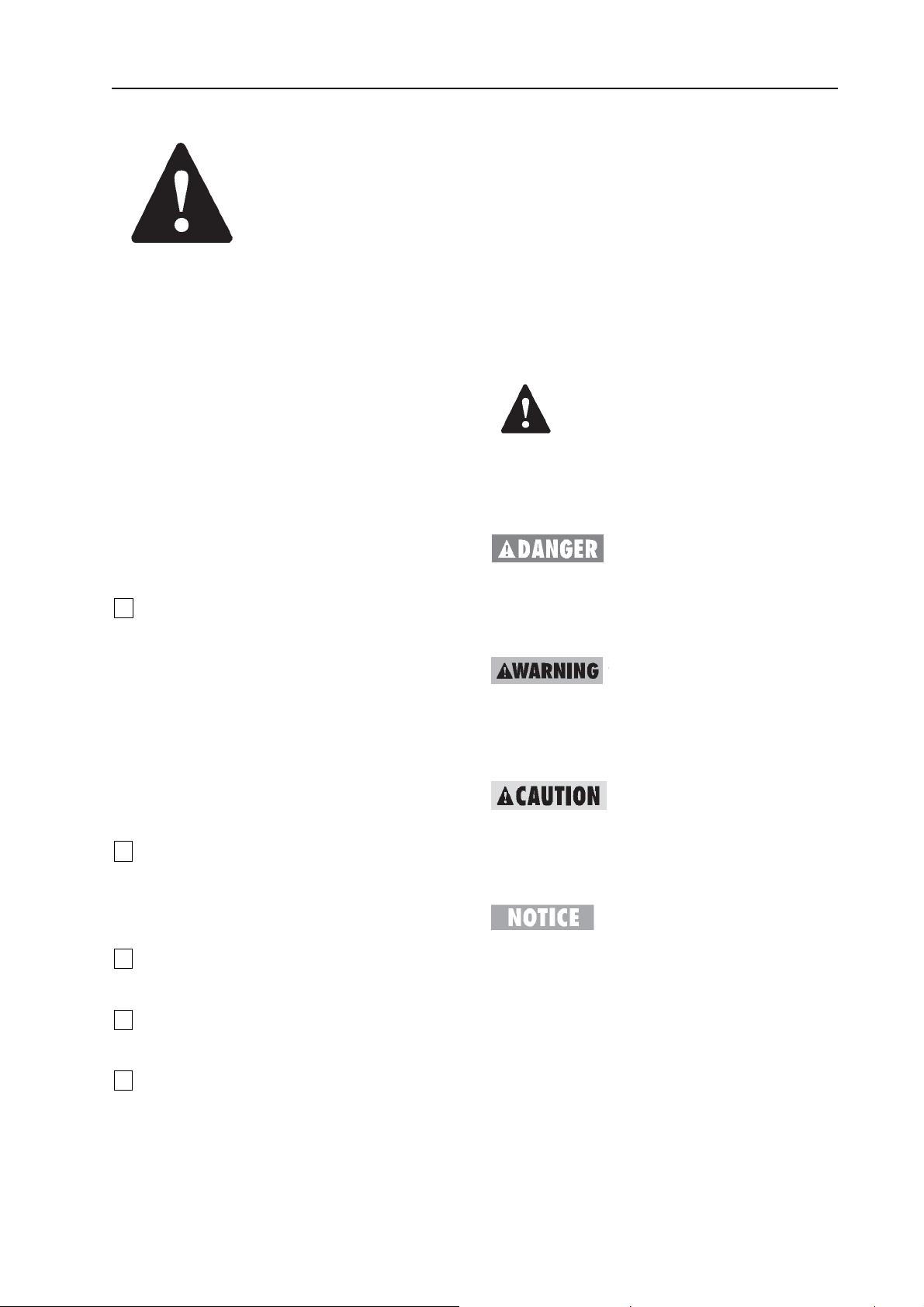
Electrocution Hazards
This machine is not electrically insulated and
will not provide protection from contact with or
proximity to electrical current.
Maintain safe distances from electrical power
lines and apparatus in accordance with
applicable governmental regulations and the
following chart.
Voltage
Phase to Phase
Minimum Safe
Approach Distance
Meters
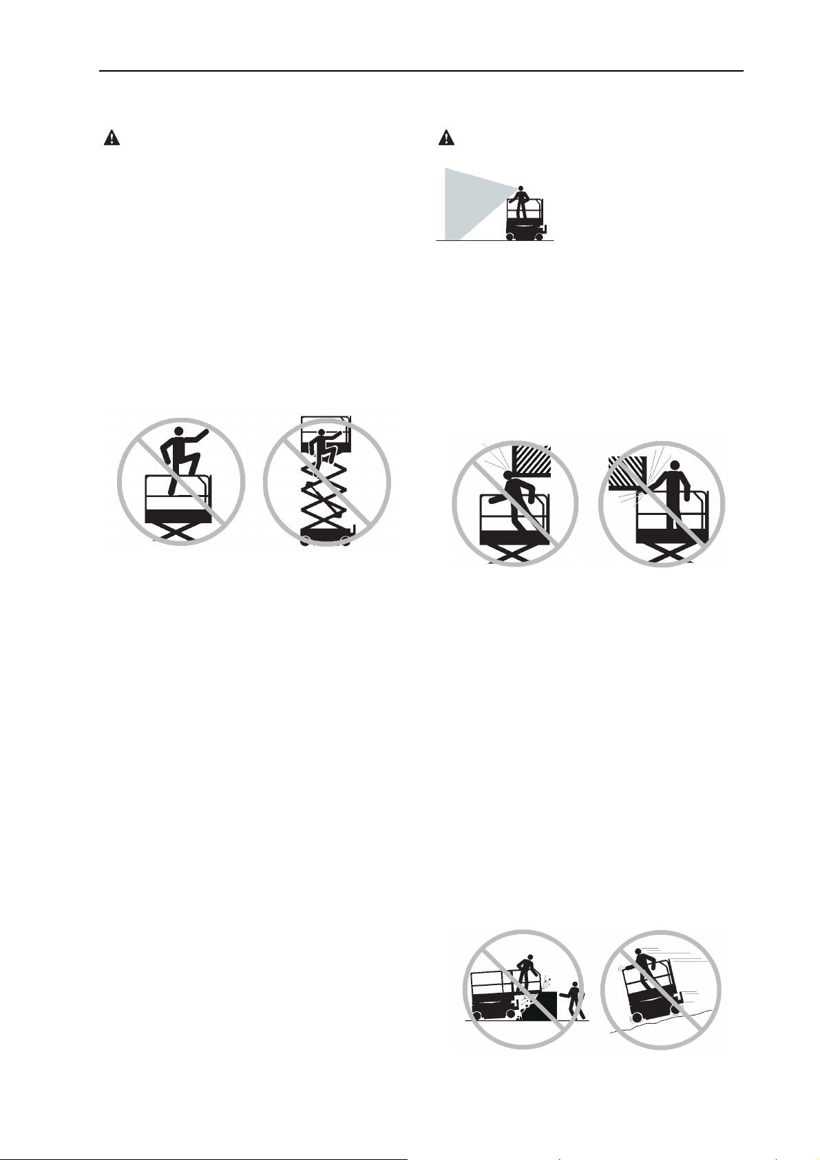
Tip-over Hazards
This machine is intended for use INDOORS
ONLY, and must not be used outdoors as
wind forces may make it unstable.
Occupants, equipment and materials must not
exceed the maximum platform capacity.
Maximum capacity – SPX10
Maximum occupants 2
ximum platform capacity 240 kg
Ma
0 to 300V Avoid Contact
300V to 50KV 3.05
50KV to 200KV 4.60
200KV to 350KV 6.10
350KV to 500KV 7.62
500KV to 750KV 10.67
750KV to 1000KV 13.72
Allow for platform movement, electrical line
sway or sag and beware of strong or gusty
winds.
Keep away from the machine if it contacts
energized power lines. Personnel on the ground
or in the platform must not touch or operate the
machine until energized power lines are shut
off.
Do not operate the machine during lightning or
storms.
Do not use the machine as a ground for
welding.
2
Page 7
OPERATOR’S MANUAL with Maintenance Information
Safety Rules
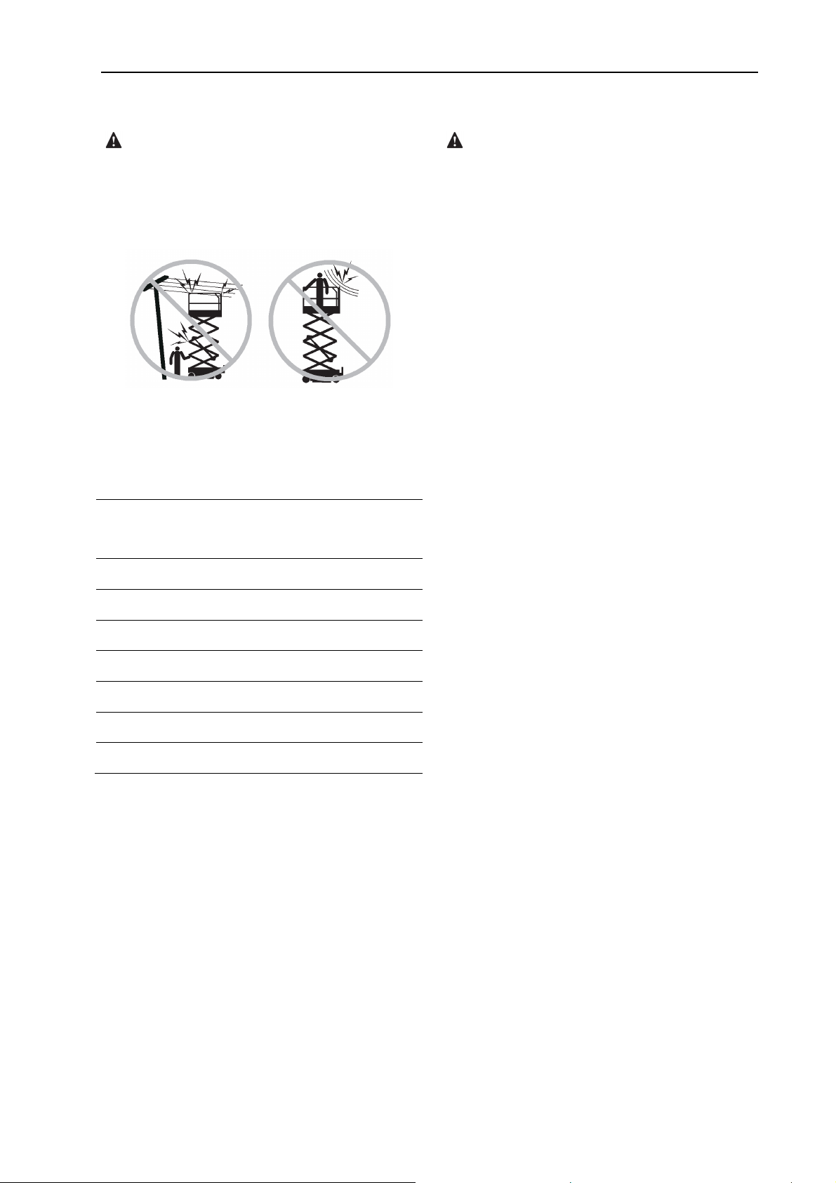
o not raise the platform unless the machine is
D
on a firm, level surface.
Do not drive over 0.8 km/h with the platform
raised.
Do not depend on the tilt alarm as a level
indicator.
The tilt alarm sounds on the chassis and in the
platform when the machine is on a slope.
If the tilt alarm sounds:
Lower the platform. Move the machine to a firm,
level surface. If the tilt alarm sounds when the
platform is raised, use extreme caution to lower
the platform.
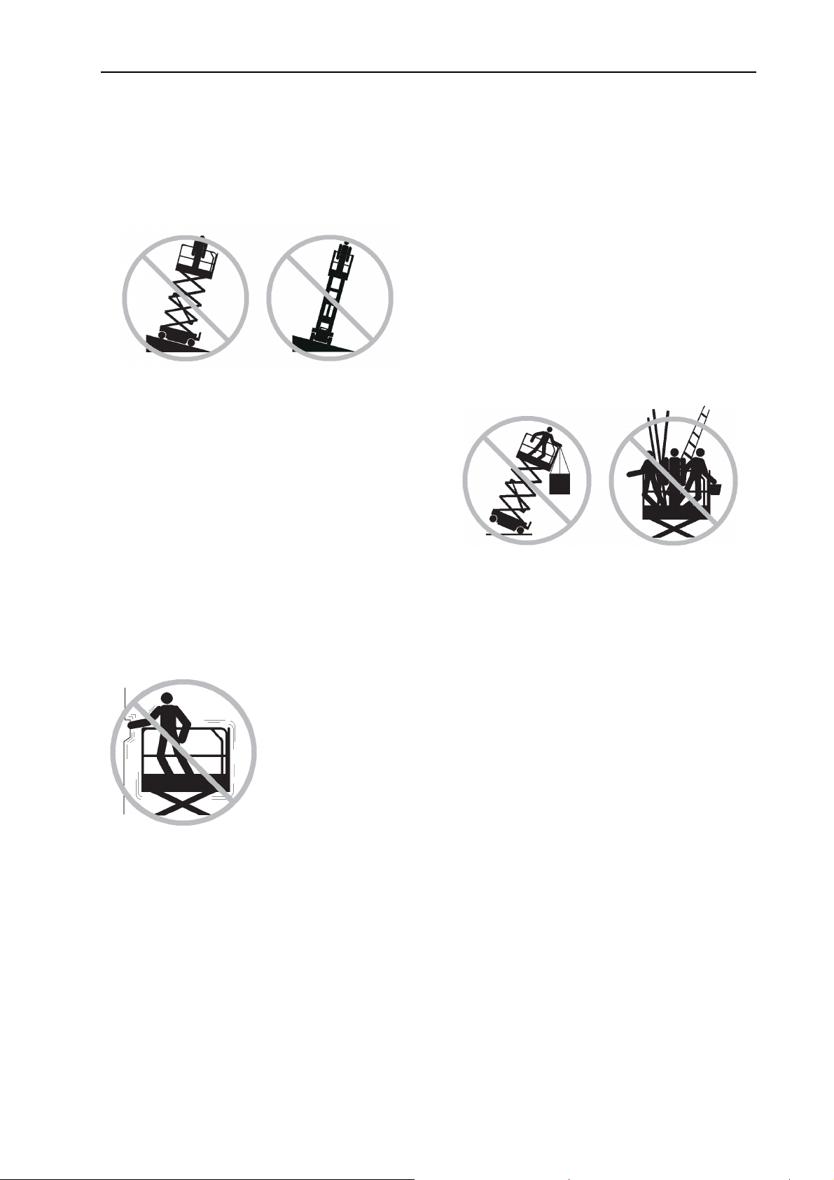
Do not push off or pull toward any object
outside of the platform.
loads to any part of this machine.
Do not place ladders or scaffolds in the platform
or against any part of this machine.
Be sure all tires are in good condition, castle
nuts are properly tightened and cotter pins are
properly installed.
Do not use batteries that weigh less than the
original equipment. Batteries are used as
counterweight and are critical to machine
stability.
Each battery must weigh 17.5 kg.
Do not use the machine as a crane.
Do not push the machine or other objects with
the platform.
Do not contact adjacent structures with the
platform.
Maximum allowable manual force 200 N
Do not drive the machine on or near uneven
terrain, unstable surfaces or other hazardous
conditions with the platform raised.
Do not replace items critical to machine stability
with items of different weight or specification.
Do not use the machine on a moving or mobile
surface or vehicle.
Do not place or attach fixed or overhanging
Do not tie the platform to adjacent structures.
3
Page 8
OPERATOR’S MANUAL with Maintenance Information
Safety Rules
Fall Hazards
The guard rail system provides fall protection. If
occupant(s) of the platform are required to wear
personal fall protection equipment (PFPE) due
to job site or employer rules, PFPE equipment
and its use shall be in accordance with the
PFPE manufacturer’s instructions and
applicable governmental requirements.
Do not sit, stand or climb on the platform guard
rails. Maintain a firm footing on the platform
floor at all times.
Collision Hazards
Be aware of limited sight distance and blind
spots when driving or operating.
Operators must comply with employer, job site
and governmental rules regarding use of
personal protective equipment.
Check the work area for overhead obstructions
or other possible hazards.
Do not climb down from the platform when
raised.
Keep the platform floor clear of debris.
Close the entry gate before operating.
Do not operate the machine unless the guard
rails are properly installed and the entry is
secured for operation.
Be aware of crushing hazards when grasping
the platform guard rail.
Observe and use color-coded direction arrows
on the platform controls and platform decal
plate for drive and steer functions.
Do not operate a machine in the path of any
crane or moving overhead machinery unless
the controls of the crane have been locked out
and/or precautions have been taken to prevent
any potential collision.
No stunt driving or horseplay while operating a
machine.
Do not lower the platform unless the area below
is clear of personnel and obstructions.
4
Page 9

OPERATOR’S MANUAL with Maintenance Information
i
mit travel speed according to the condition of
L
the ground surface, congestion, slope, location
of personnel, and any other factors which may
cause collision.
Component Damage Hazards
Do not use any battery or charger greater than
24V.
Safety Rules
operating the machine with the controller from
the ground. Maintain safe distances between
the operator, the machine and fixed objects.
Maintain a firm grasp on the platform rail when
removing the rail pins. Do not allow the platform
guard rails to fall.
Bodily Injury Hazard
Do not use the machine as a ground for
welding.
Explosion and Fire Hazards
Do not operate the machine in hazardous
locations or locations where potentially
flammable or explosive gases or particles may
be present.
Damaged Machine Hazards
Do not use a damaged or malfunctioning
chine.
ma
Conduct a thorough pre-operation inspection of
the machine and test all functions before each
work shift. Immediately tag and remove from
service a damaged or malfunctioning machine.
Do not operate the machine with a hydraulic oil
air leak. An air leak or hydraulic leak can
or
penetrate and/or burn skin.
Improper contact with components under any
cover will cause serious injury. Only trained
maintenance personnel should access
compartments. Access by the operator is only
advised when performing a pre-operation
inspection. All compartments must remain
closed and secured during operation.
.
Be sure all maintenance has been performed as
specified in this manual and the appropriate
UPRIGHT service manual.
Be sure all decals are in place and legible.
Be sure the operator’s, safety and
responsibilities manuals are complete, legible
and in the storage container located in the
platform.
Crushing Hazards
Keep hands and limbs out of scissors.
common sense and planning when
Use
5
Page 10
Battery Safety
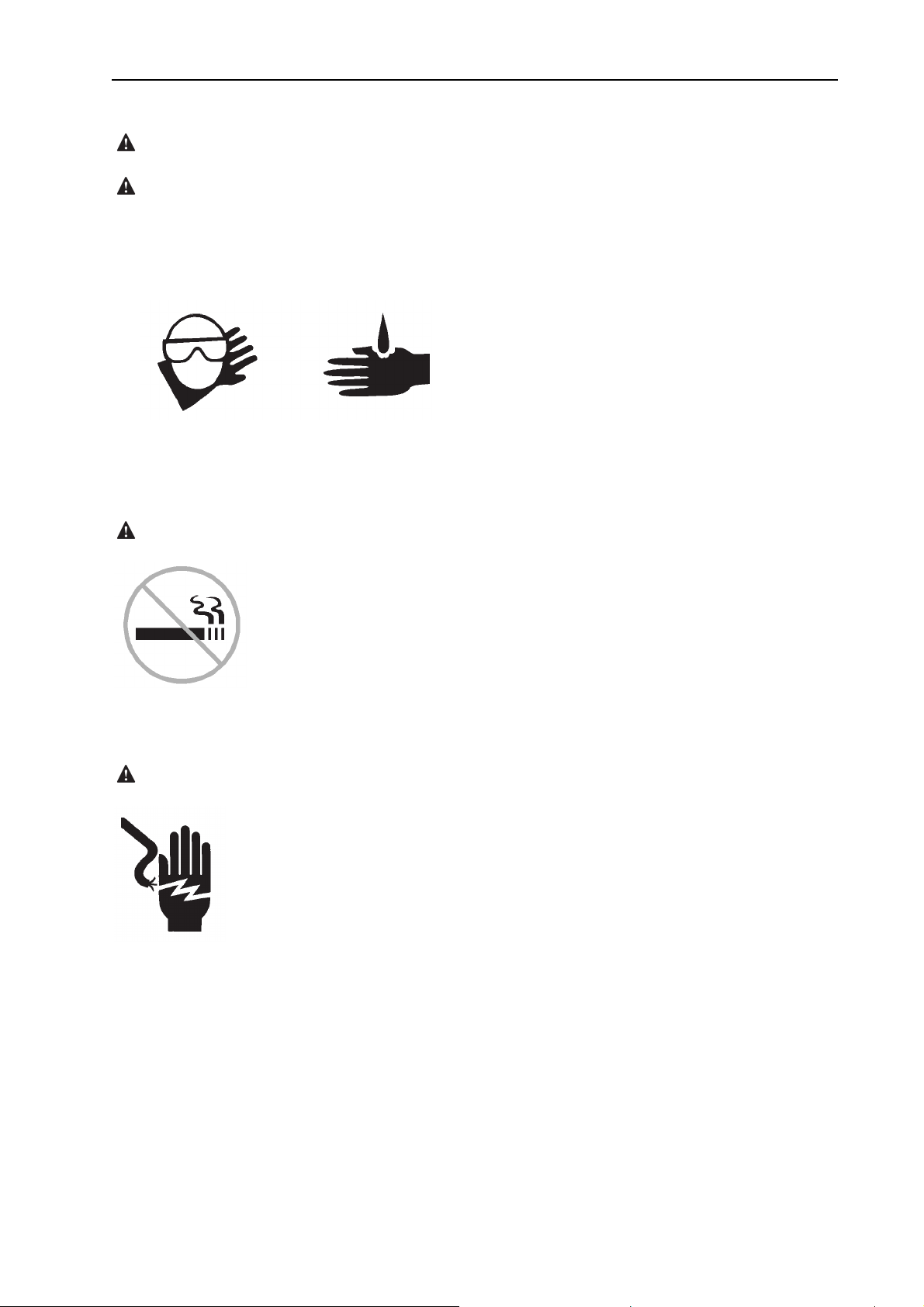
Burn Hazards
Batteries contain acid. Always wear protective
clothing and eye wear when working with
batteries.
Avoid spilling or contacting battery acid.
Neutralize battery acid spills with baking soda
and water.
OPERATOR’S MANUAL with Maintenance Information
Safety Rules
Explosion Hazard
Keep sparks, flames and lighted tobacco away
from batteries. Batteries emit explosive gas.
Electrocution Hazard
Avoid contact with electrical terminals.
6
Page 11
OPERATOR’S MANUAL with Maintenance Information
Safety Rules
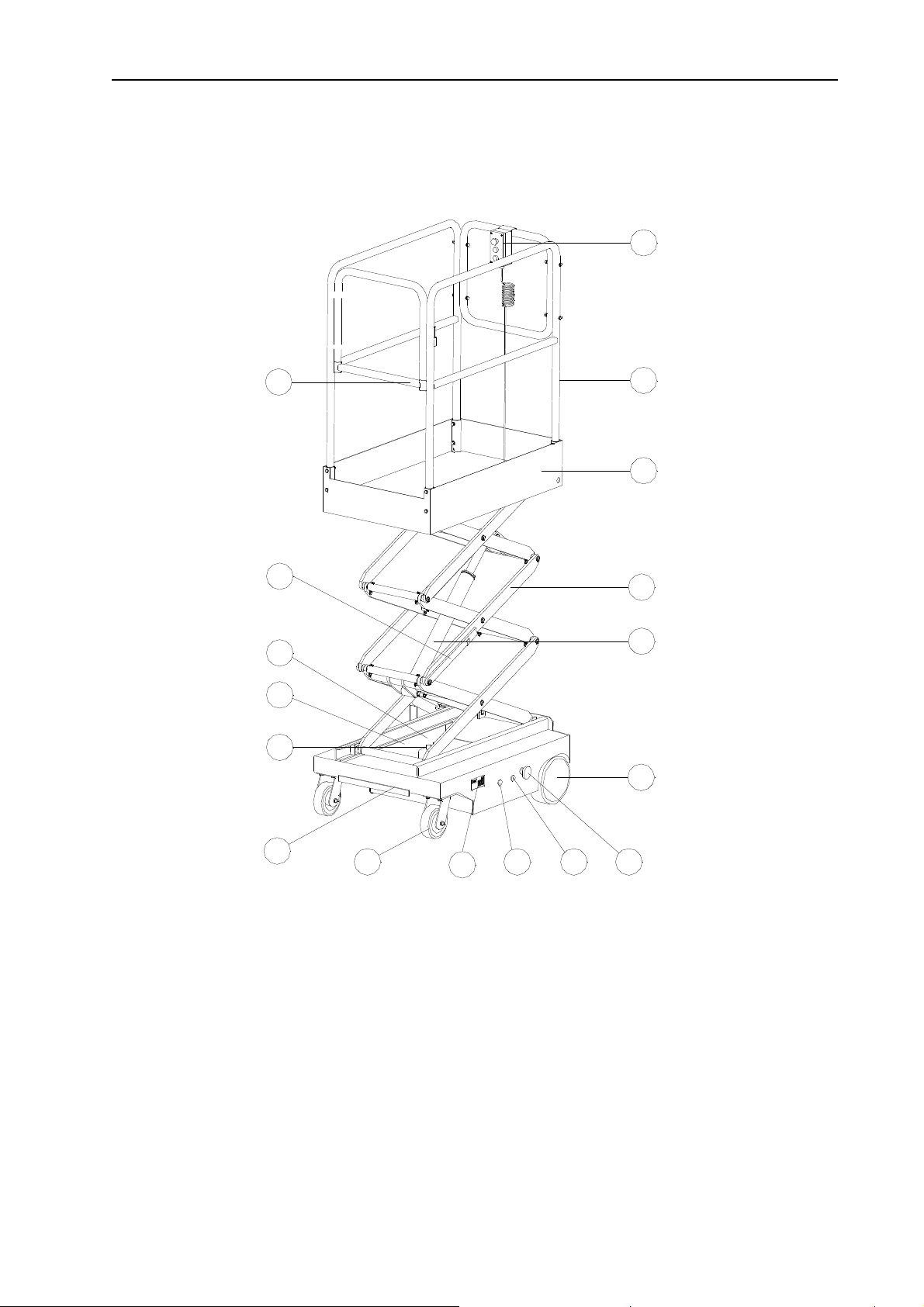
Legend
17
16
15
14
13
12
Platform controller
1
11
2 Platform guard rails
3 Platform
4 Scissor
5 Hydraulic cylinder
6 Drive wheels
7 Red Emergency Stop button
8 Key switch for power
9 Power indicator light
1
2
3
4
5
6
10
9 8 7
10 Charger
11 Steer tire
12 Step
13 Batteries
14 Auxiliary lowering knorb (hidden from view)
15 Hydraulic power pack
16 Safety arms
17 Platform entry gate
7
Page 12
OPERATOR’S MANUAL with Maintenance Information
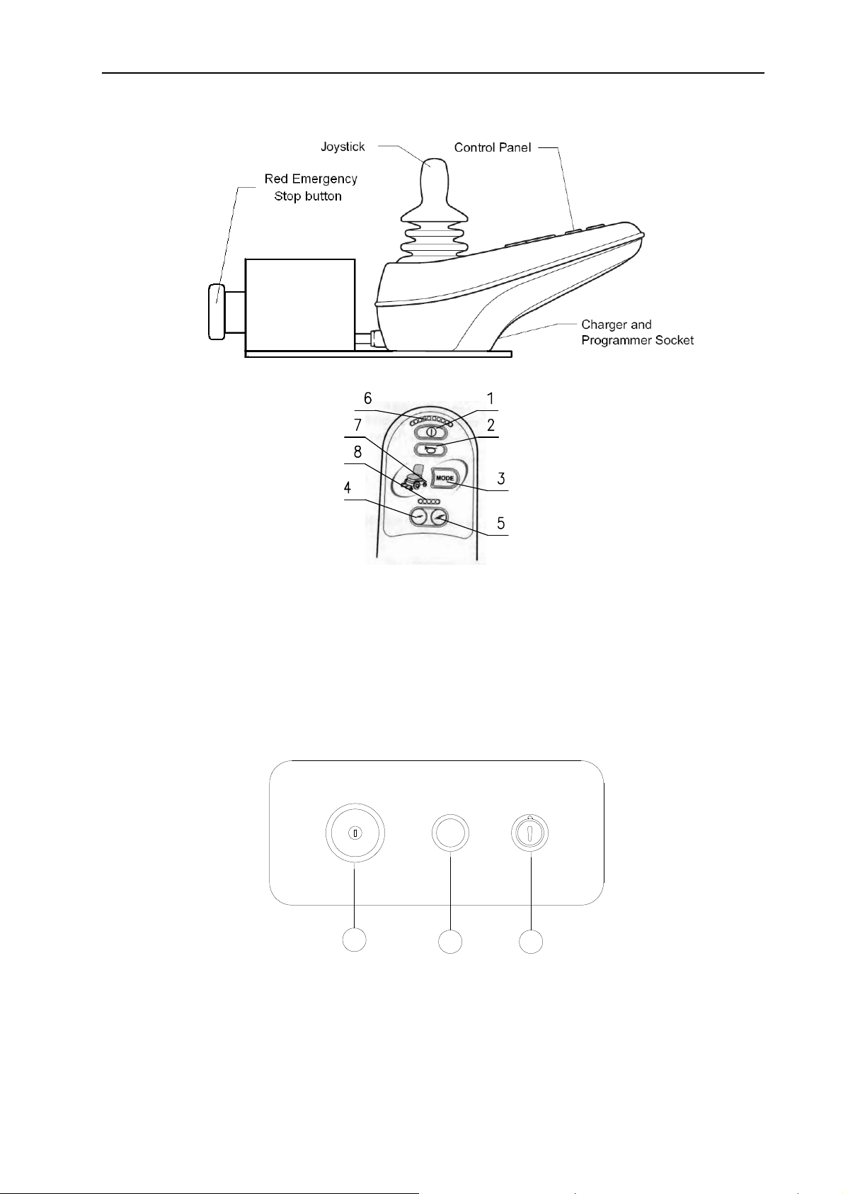
Control Panel
`
Joystick Control Panel
Platform Joystick controller
1 On-off button 5
2 Horn button 6 Battery indicator light
3 Mode button 7 Mode indicator
4 Decelerating button 8 Drive speed indicator
3
Accelerating button
2 1
Ground Control Panel
1 Key switch 2 Power indicator 3 Red Emergency Stop button
8
Page 13

OPERATOR’S MANUAL with Maintenance Information
Pre-operation Inspection
Do Not Operate Unless:
√ You learn and practice the principles of safe
machine operation contained in this operator's
manual.
1 Avoid hazardous situations.
2 Always perform a pre-operation
inspection.
Know and understand the pre-operation
inspection before going on to the next
section.
3 Always perform function tests prior to use.
4 Inspect the workplace.
5 Only use the machine as it was intended.
Fundamentals
It is the responsibility of the operator to perform
a
pre-operation inspection and routine
maintenance.
The pre-operation inspection is a visual
inspection performed by the operator prior to
each work shift. The inspection is designed to
discover if anything is apparently wrong with a
machine before the operator performs the
function tests.
The pre-operation inspection also serves to
determine if routine maintenance procedures
are required. Only routine maintenance items
specified in this manual may be performed by
the operator.
Refer to the list on the next page and check
each of the items.
If damage or any unauthorized variation from
factory delivered condition is discovered, the
machine must be tagged and removed from
service.
Repairs to the machine may only be made by a
qualified service technician, according to the
manufacturer's specifications. After repairs are
completed, the operator must perform a
pre-operation inspection again before going on
to the function tests.
Scheduled maintenance inspections shall be
performed by qualified service technicians,
according to the manufacturer's specifications
and the requirements listed in the
responsibilities manual.
9
Page 14

OPERATOR’S MANUAL with Maintenance Information
Pre-operation Inspection
Pre-operation Inspection
Be sure that the operator’s, safety and
□
responsibilities manuals are complete, legible
and in the storage container located in the
platform.
□ Be sure that all decals are legible and in place.
See Decals section.
□ Check for hydraulic oil leaks and proper oil
level. Add oil if needed. See Maintenance
section.
□ Check for battery fluid leaks and proper fluid
level. Add distilled water if needed. See
Maintenance section.
Check the following components or areas for
damage, improperly installed or missing parts
and unauthorized modifications:
components are present and all associated
fasteners and pins are in place and properly
tightened
□ Side rails are installed and bolts are
fastened
□ Electrical components, wiring and electrical
cables
□ Hydraulic hoses, fittings, cylinders
□ Hydraulic tanks
□ Drive motors
□ Wear pads
□ Tires and wheels
□ Limit switches, alarms
□ Nuts, bolts and other fasteners
□ Platform entry gate
□ Beacon and alarms (if equipped)
□ Safety arm
□ Scissor pins and retaining fasteners
□ Platform control joystick
Check entire machine for:
□ Cracks in welds or structural components
□ Dents or damage to machine
□ Be sure that all structural and other critical
10
Page 15

OPERATOR’S MANUAL with Maintenance Information
Maintenance
Observe and Obey:
□ Only routine maintenance items specified in
this manual shall be performed by the operator.
□ Scheduled maintenance inspections shall be
completed by qualified service technicians,
according to the manufacturer's specifications
and the requirements specified in the
responsibilities manual.
Maintenance Symbols Legend
The following symbols have
been used in this manual to help communicate
the intent of the instructions. When one or more
of the symbols appear at the beginning of a
maintenance procedure, it conveys the
meaning below.
Indicates that tools will be required to
perform this procedure.
Check the Batteries
Proper battery condition is essential to good
engine performance and operational safety.
Improper fluid levels or damaged cables and
connections can result in engine component
damage and hazardous conditions.
Electrocution hazard
Contact with hot or live circuits may result in
death or serious injury. Remove all rings,
watches and other jewelry.
Bodily injury hazard
Batteries contain acid. Avoid spilling or
contacting battery acid. Neutralize battery acid
spills with baking soda and water.
1 Put on protective clothing and eye wear.
Indicates that new parts will be required
to perform this procedure.
2 Be sure that the battery cable
connections are tight and free of
corrosion.
3 Be sure that the battery hold-down bars
are secure.
4 Remove the battery vent caps.
5 Check the battery acid level. If needed,
replenish with distilled water to the bottom
of the battery fill tube. Do not overfill.
6 Install the vent caps.
11
Page 16

OPERATOR’S MANUAL with Maintenance Information
Maintenance
Check the Hydraulic Oil Level
Maintaining the hydraulic oil at the proper level
is essential to machine operation. Improper
hydraulic oil levels can damage hydraulic
components. Daily checks allow the inspector to
identify changes in oil level that might indicate
the presence of hydraulic system problems.
Perform this procedure with the
platform in the stowed position
The hydraulic oil level can be checked by
removing the filler cap fitted to the hydraulic oil
tank. The correct amount of oil is in the tank
when hydraulic fluid appears on the tip of the
dipstick. This check must be carried out with the
platform is in the level surface.
The hydraulic oil can be topped up by adding oil
to the filler located. Take care not to spill
hydraulic fluid over any of the surrounding
machine components.
The hydraulic oil can be drained by removing
the tank by removing the bolts and separating
the tank from the pump body. The hydraulic
fluid can then be correctly disposed of.
Re-assembly is the reverse of above.
Hydraulic oil specifications
The hydraulic oil recommended for use with this
machine is: Mineral basis hydraulic oil with
lubricating, antifoaming, anti-corrosive,
antioxidant HL - HLP (ISO and UNI HM) – HV HLPD performances according to DIN51524
part 1 2 standards.‐
-18℃~-5 10W℃
-18℃~99 10W℃ -20,10W-30
12
Page 17

OPERATOR’S MANUAL with Maintenance Information
Scheduled Maintenance
Maintenance performed quarterly, annually and
very two years must be completed by a person
e
trained and qualified to perform maintenance on
this machine according to the procedures found
in the service manual for this machine.
Machines that have been out of service for
more than three months must receive the
quarterly inspection before they are put back
into service.
Maintenance
13
Page 18

OPERATOR’S MANUAL with Maintenance Information
Function Tests
Do Not Operate Unless:
√ You learn and practice the principles of safe
machine operation contained in this operator's
manual.
1 Avoid hazardous situations.
2 Always perform a pre-operation inspection.
3 Always perform function tests prior to
use.
Know and understand the function tests
before going on to the next section.
4 Inspect the workplace.
5 Only use the machine as it was intended.
Fundamentals
The function tests are designed to discover any
m
alfunctions before the machine is put into
service.
The operator must follow the step-by-step
instructions to test all machine functions.
A malfunctioning machine must never be used.
If malfunctions are discovered, the machine
must be tagged and removed from service.
Repairs to the machine may only be made by a
qualified service technician, according to the
manufacturer's specifications.
After repairs are completed, the operator must
perform a pre-operation inspection and function
tests again before putting the machine into
service.
14
Page 19

OPERATOR’S MANUAL with Maintenance Information
Function Tests
Select a test area that is firm, level and free
1
of obstruction.
2 Be sure the battery pack is connected.
3 Pull out the platform and ground red
Emergency Stop buttons to the on position.
4 Turn the key switch to power on.
☉☉☉☉ Result: The Power indicator will light.
Test Emergency Stop
5 Push in the ground red Emergency Stop
b
utton to the off position.
☉☉☉☉ Result: The Power indicator will turn off and
no functions should operate.
6 Pull out the red Emergency Stop button to
the on position.
At the Platform Controls
Test Emergency Stop
7 Push in the platform red Emergency Stop
button to the off position.
☉☉☉☉ Result: No functions should operate.
8 Turn the red Emergency Stop button
clockwise to the on position.
Test the On-off function
9 Press the on-off button to power on.
☉ Result: the power indicator should light.
☉
☉
☉
10 Press the on-off button to power off.
☉☉☉☉ Result:. No functions should operate.
11 Press the on-off button to power on.
Test Up/Down Functions and Function
Enable
14 Press the On-off button to power on.
15 Press the mode button to select lift function.
16 Move the joystick to forward direction.
☉☉☉☉ Result: The platform should raise.
17 Move the joystick to backward direction.
☉☉☉☉ Result: The platform should lower then stop
at the height is 0.7 m.
18
Wait for seconds. Move the joystick to
backward direction to lower the platform
fully
Test the Steering
Note: When performing the steer and drive
function tests, stand in the platform facing the
steer end of the machine.
19 Press the mode button to select drive
function.
20 Move the joystick to left direction.
☉☉☉☉ Result: The steer wheels should turn. The
machine should turn to left.
21 Move the joystick to right direction.
☉☉☉☉ Result: The steer wheels should turn. The
machine should turn to right.
Test Drive and Braking
22 Slowly move the joystick to forward
irection, then return the joystick to the
d
center position.
☉☉☉☉ Result: The machine should move forward
then come to an abrupt stop.
23 Slowly move the joystick to downward
direction, then return the joystick to the
center position.
12 Press the on-off button to power off.
3 Move the joystick forward or backward
1
☉☉☉☉ Result: The platform should not raised.
☉☉☉☉ Result: The machine should move backward
then come to an abrupt stop.
Note: The brakes must be able to hold the
machine on any slope it is able to climb.
15
Page 20

OPERATOR’S MANUAL with Maintenance Information
Test Limited Drive Speed
24 Press the mode button to active the lift
function. Move the joystick to raise the
platform approximately 0.75 m from the
ground.
25 Press the mode button to select drive
function.
26 Press the decelerating button until only one
indicator light.
27 Slowly move the joystick to the full drive
position.
☉☉☉☉ Result: The maximum achievable drive
speed with the platform raised should not
exceed 31 cm/s. If the drive speed with the
platform raised exceeds 31 cm/s,
mediately tag and remove the machine
im
from service.
Function Tests
Test Auxiliary Lowering
28 Move the joystick to forward direction to
raise the platform approximately 60 cm.
29 Push in the red Emergency Stop button to
cut off the power.
30 Pull the auxiliary lowering knob at the
chassis side out.
☉☉☉☉ Result: The platform should lower to end.
16
Page 21

OPERATOR’S MANUAL with Maintenance Information
Workplace Inspection
Do Not Operate Unless:
√ You learn and practice the principles of safe
machine operation contained in this operator's
manual.
1 Avoid hazardous situations.
2 Always perform a pre-operation inspection.
3 Always perform function tests prior to use.
4 Inspect the workplace.
Know and understand the workplace
inspection before going on to the next
section.
5 Only use the machine as it was intended.
Fundamentals
The workplace inspection helps the operator
d
etermine if the workplace is suitable for safe
machine operation. It should be performed by
the operator prior to moving the machine to the
workplace.
It is the operator's responsibility to read and
remember the workplace hazards, then watch
for and avoid them while moving, setting up and
operating the machine.
17
Page 22

OPERATOR’S MANUAL with Maintenance Information
Workplace Inspection
Be aware of and avoid the following hazardous
situations:
- Drop-offs or holes
- Bumps, floor obstructions or debris
- Sloped surfaces
- Unstable or slippery surfaces
- Overhead obstructions and high voltage
conductors
- Hazardous locations
- Inadequate surface support to withstand all
load forces imposed by the machine
Workplace Inspection
- The presence of unauthorized personnel
- Other possible unsafe conditions
18
Page 23

Do Not Operate Unless:
You learn and practice the principles of safe
√
machine operation contained in this operator's
manual.
1 Avoid hazardous situations.
2 Always perform a pre-operation inspection.
3 Always perform function tests prior to use.
4 Inspect the workplace.
5 Only use the machine as it was intended.
OPERATOR’S MANUAL with Maintenance Information
Operating Instructions
Fundamentals
The Operating Instructions section provides
i
nstructions for each aspect of machine
operation.
It is the operator's responsibility to follow all the
safety rules and instructions in the operator's,
safety and responsibilities manuals.
Using the machine for anything other than lifting
personnel, along with their tools and materials,
to an aerial work site is unsafe and dangerous.
Only trained and authorized personnel should
be permitted to operate a machine. If more than
one operator is expected to use a machine at
different times in the same work shift, they must
all be qualified operators and are all expected to
follow all safety rules and instructions in the
operator's, safety and responsibilities manuals.
That means every new operator should perform
a pre-operation inspection, function tests, and a
workplace inspection before using the machine.
19
Page 24

Emergency Stop
OPERATOR’S MANUAL with Maintenance Information
Operating Instructions
unction.
f
Push in the red Emergency Stop button to the
off position at the ground controls or the
platform controls to stop all machine functions .
Repair any function that operates when either
red Emergency Stop button is pushed in.
Operation from Ground
1 Pull out both ground and platform red
mergency Stop buttons to the on position.
E
2 Turn the key switch to power on.
3 Be sure the battery pack is connected
before operating the machine.
Lift and Drive and steer functions are not
available from the ground controls.
Operation from Platform
1 Pull out the ground and platform red
Emergency Stop buttons to the on position.
2 Move the joystick forward to drive the
machine to forward direction.
3 Move the joystick backward to drive the
machine to backward direction.
4 Increase speed: Press the celerating
button.
Decrease speed: Press the decelerating
button.
Stop: Return the joystick to center or press
the On-off button.
Machine travel speed is restricted when the
platform is raised.
Auxiliary Lowering
At the Ground Controls
In the event of a power failure, use the backup
a
uxiliary lowering function.
2 Press the mode button to select lift function.
3 Be sure the battery pack is connected
before operating the machine.
To Position Platform
1 Move the joystick forward to raise the
latform.
p
2 Move the joystick backward to lower the
platform.
To Steer
1 Press the mode button to select the drive
function.
2 Move the joystick left to turn the machine to
left direction.
3 Move the joystick right to turn the machine
to right direction.
How to use the Safety Arm
1 Raise the platform approximately 1.3 m
rom the ground.
f
2 Rotate the safety arm away from the
machine and let it hang down.
3 Lower the platform until the safety arm rests
securely on the link. Keep clear of the safety
arm when lowering the platform.
To Drive
1 Press the mode button to select the drive
20
Page 25

OPERATOR’S MANUAL with Maintenance Information
Operating Instructions
Fall Protection
Personal fall protection equipment (PFPE) is
not required when operating this machine. If
PFPE is required by job site or employer rules,
the following shall apply:
All PFPE must comply with applicable
governmental regulations and must be
inspected and used in accordance with the
manufacturer’s instructions.
Operation From Ground with
Controller
Maintain safe distances between the operator,
machine and fixed objects.
Be aware of the direction the machine will travel
when using the controller.
After Each Use
1 Select a safe parking location—firm level
surface, clear of obstructions and traffic.
2 Lower the platform.
3 Turn the key switch to the off position and
remove the key to secure from unauthorized
use.
4 Chock the wheels.
5 Charge the batteries.
21
Page 26

OPERATOR’S MANUAL with Maintenance Information
Operating Instructions
Charge Batteries
To
Battery and Charger Instructions
Observe and Obey:
√ Do not use an external charger or booster
battery.
√ Charge the battery in a well-ventilated area.
√ Use proper AC input voltage for charging as
indicated on the machine.
√ Use only a UPRIGHT authorized battery and
charger.
Dry Battery Filling and Charging
Instructions
1 Remove the battery vent caps and
permanently remove the plastic seal from
the battery vent openings.
2 Fill each cell with battery acid (electrolyte)
until the level is sufficient to cover the
plates.
1 Be sure the batteries are connected before
ch
rging.
a
2 Open the battery compartment. The
compartment should remain open for the
entire charging cycle.
Maintenance - free batteries
3 Connect the battery charger to a grounded
circuit.
AC
4 The charger will indicate when the battery
is fully charged.
Standard Batteries
3 Remove the battery vent caps and check
the battery acid level. If necessary, add
only enough distilled water to cover the
plates. Do not overfill prior to the charge
cycle.
4 Replace the battery vent caps.
5 Connect the battery charger to a grounded
AC circuit.
Do not fill to the maximum level until the battery
charge cycle is complete. Overfilling can cause
the battery acid to overflow during charging.
Neutralize battery acid spills with baking soda
and water.
3 Install the battery vent caps.
4 Charge the battery.
5 Check the battery acid level when the
charging cycle is complete. Replenish with
distilled water to the bottom of the fill tube.
Do not overfill.
Note: For optional charger/inverter, connect AC
power to the plug on the back of the machine.
6 The charger will indicate when the battery
is fully charged.
22
Page 27

OPERATOR’S MANUAL with Maintenance Information
Transport and Lifting Instructions
Observe and Obey:
√ Common sense and planning must be
applied to control the movement of the machine
when lifting it with a crane or forklift.
Lifting the Machine with a Forklift
Be sure the controls and component trays are
se
cure.
Remove all loose items on the machine.
√ The transport vehicle must be parked on a
level surface.
√ The transport vehicle must be secured to
prevent rolling while the machine is being
loaded.
√ Be sure the vehicle capacity, loading
surfaces and chains or straps are sufficient to
withstand the machine weight. See the serial
label for the machine weight.
√ The machine must be on a level surface or
secured before releasing the brakes.
Fully lower the platform.
The platform must remain lowered during all
loading and transport procedures.
Use the forklift pockets located on both sides.
Brake Release Operation
1 Chock the wheels to prevent the machine
rom rolling.
f
2 Be sure the winch line is properly secured
to the drive chassis tie points and the path
is clear of all obstructions.
3 Turn the key switch to power on.
4 Pull out both ground and platform red
Emergency Stop buttons to the on position.
5 Press the mode button to drive position.
6 Move the joystick to drive position to
release the brakes.
After the machine is loaded:
1 Chock the wheels to prevent the machine
from rolling.
2 Push in both ground and platform red
Emergency Stop buttons to the off position.
3 Turn the key switch to the off position.
23
Page 28

OPERATOR’S MANUAL with Maintenance Information
Transport and Lifting Instructions
Securing to Truck or Trailer for
Transit
Always chock the machine wheels in
preparation for transport.
Turn the key switch to the off position and
remove the key before transporting.
Inspect the entire machine for loose or
unsecured items.
Use a minimum of four chains or straps.
Use chains or straps of ample load capacity.
24
Page 29

OPERATOR’S MANUAL with Maintenance Information
Decals
Decal Inspection
Use the pictures on the next page to verify that
all decals are legible and in place.
Below is a numerical list with quantities and
descriptions.
9213011 Label-Maximum Capacity 240kg 2
9411003 Danger-Crushing Hazard 2
9413011 Warning-Tip-over Hazard 2
9413013 Warning-Crushing Hazard/Fall Hazard 2
9413015 Danger-Electrocution Hazard 2
9413017 Warning-Inspect and Maintain Properly 2
9421031 Warning-Explosion/Burn Hazard 1
9441019 Warning-Recharging in Time 1
9441023 Label- Direction al Arrows 1
9443019 Notice-Charge Time 1
25
Page 30

OPERATOR’S MANUAL with Maintenance Information
Decals
SPX10
Green - used to indicate operation or
maintenance information.
Shading indicates
that decal is hidden
from view
26
Page 31

OPERATOR’S MANUAL with Maintenance Information
Specifications
SPX10
Height, working maximum 5 m
Height, platform maximum 3 m
Height, stowed maximum 1.65 m
Width 0.7 m
Length 1.14 m
Maximum load capacity 240 kg
Maximum wind speed 0 m/s
Wheelbase 0.85 m
Turning radius (outside) 2.5 m
Ground clearance 6 cm
Weight 418kg
Specification
Gradeability 30%
Maximum hydraulic pressure 110 bar
Tire size 6” Caster 230 x 80
Platform length x width 1.14 x 0.7 m
Stowed, maximum drive speeds 4 km/h
Platform raised, maximum drive speeds 0.8 km/h
Airborne noise emissions 70 dB
Maximum sound level at normal operating workstations (A-weighted)
Floor loading information
Tire load, maximum 500 kg
Tire contact pressure 983 kg/mm2
Occupied floor pressure 824 kg/mm2
Note: Floor loading information is approximate and does not incorporate different option configurations.
It should be used only with adequate safety factors.
Continuous improvement of our products is a UPRIGHT policy. Product specifications are subject to change without
notice or obligation.
27
Page 32

H
ydraulic Schematic
OPERATOR’S MANUAL with Maintenance Information
Schematic
CYLINDER
SOLENOID
RETURN
VALVE
MOTOR
M
FLOW
REGULATOR
NON
RETURN
VALVE
PUMP
FILTER
F
ILTER
RELIEF
VALVE
E
MERGENCY
RELEASE
VALVE
ESERVOIR
R
28
Page 33

E
lectrical Schematic
D
V
OPERATOR’S MANUAL with Maintenance Information
Schematic
T
2
M
K
F
F
A
T
K
K
U
O
/
N
I
V
Y
F
A
K
1
M
K
H
R
F
T
K
1
S
V
2
A
1
/
V
2
C
D
E
Q
Q
Charger
V
2
2
C
A
+
+
r
o
t
o
m
2
B
S
1
B
S
2
U
F
D
M
E
S
L
J
harge protect
C
Horn
Power
B
S
U
+
e
k
a
r
b
1
M
K
Lift
High speed drive
Low speed Drive
Speed contorl
F
T
Drive
N
D
+
A
C
-
-
r
e
o
k
t
a
o
r
m
b
1
M
2
M
K
S
B
S
1
N
A
+
A
B
K
1
-
1
A
e
e
n
R
-
A
B
1
U
F
2
1
2
2
H
H
N
N
I
I
+
+
r
e
o
k
t
a
o
r
m
b
2
M
3
C
C
B
B
O
O
-
-
r
e
o
k
t
a
o
r
m
b
3
M
E
29
Page 34

OPERATOR’S MANUAL with Maintenance Information
Schematic
N
o. Symbol Description Specification Q’ty
1 IN/OUT Controller Box 1
2 YV Lower Valve Coil DC 24V 1
3 KTF Time Relay H3Y-2DC24V5A 1
4 KAF Intermediate Relay MY2NJDC24V5A 1
5 RH Power Light XB2-BVM4LC 1
6 SB2 Emergency Stop Switch ZB2BS5C/102C 1
7 SB1 Key Switch ZB2BG2C/101C 1
8 KM2 Pump Contactor W800801 80% 1
9 KM1 Power Contactor MZJ-200S1 100A 1
10 FU2 Fuse 10A 1
11 FU1 Fuse 100A 1
12 SBS Power Emergency Stop Switch 200A 1
13 SQ1 Low Limited Switch TZ8108 5A 1
14 E Battery DC12V/95Ah 2
15 M3 Hydraulic Pump Motor DC12V800W 1
16 M2 Right Drive Motor DC24V400W 1
17 M1 Left Drive Motor DC24V400W 1
18 JSM Joystick V 0~5V 1
19 Rnee Controller Rnee DC24V100A 1
20 QQE Battery Charger DC24V15A 1
30
Page 35

Maintenance
OPERATOR’S MANUAL with Maintenance Information
Maintenance and Repair Record
Date S
cheduled maintenance undertaken By
Repairs
Date Repairs undertaken By
Examinations / tests
Date Examinations / tests undertaken By
Please photocopy this page for your own use, as required
31
Page 36

Page 37

Page 38

Local Distributor:
Lokaler Vertiebshändler:
Distributeur local:
El Distribuidor local:
Il Distributore locale:
USA
TEL: +1 (559) 443 6600
FAX: +1 (559) 268 2433
Europe
TEL: +44 (0) 845 1550 058
www.upright.com
 Loading...