

Snorkel SL30RT User Manual [en, de, es, fr]

Operator Manual
Manuel de l’utilisateur
Betriebsanleitung
Manual del Operador
SL26/30RT
SL26/30RT
SERIAL NO. 9600 to Current
WARNING
All personnel shall carefully read, understand and follow all safety rules, and operating
instructions before performing maintenance on or operating any UpRight aerial work platform.
Refer to page 3 for the english language version of this Operator Manual.
AVERTISSEMENT
Tout le personnel doit lire attentivement et respecter toutes les consignes de
sécurité avant d’entretenir ou d’utiliser une plate-forme de travail aérien UpRight.
Réferez-vous à la page 11 pour la version en français de ce manuel de l’utilisateur.
WARNUNG
Alle Bediener müssen die Sicherheitsregelungen und die Betriebsanweisungen
gründlich durchlesen, verstehen und befolgen, bevor sie Wartungsarbeiten an
irgendeiner UpRight Scheren-Hubbühne vornehmen oder selbige benutzen.
Siehe Seite 19 zwecks der deutschsprachigen Ausgabe dieser Betriebsanleitung.
ADVERTENCIA
Todo el personal debe leer atentamente, entender y respetar todas las reglas de seguridad
y las instrucciones de operación antes de efectuar trabajos de mantenimiento o
manejar cualquier plataforma aérea de trabajo UpRight.
Referirse a la página 27 para la versión en español de este manual del operador.
1

Notes:
2
English Language Section
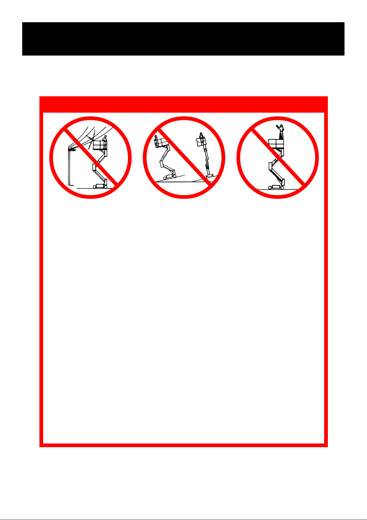
SAFETY RULES
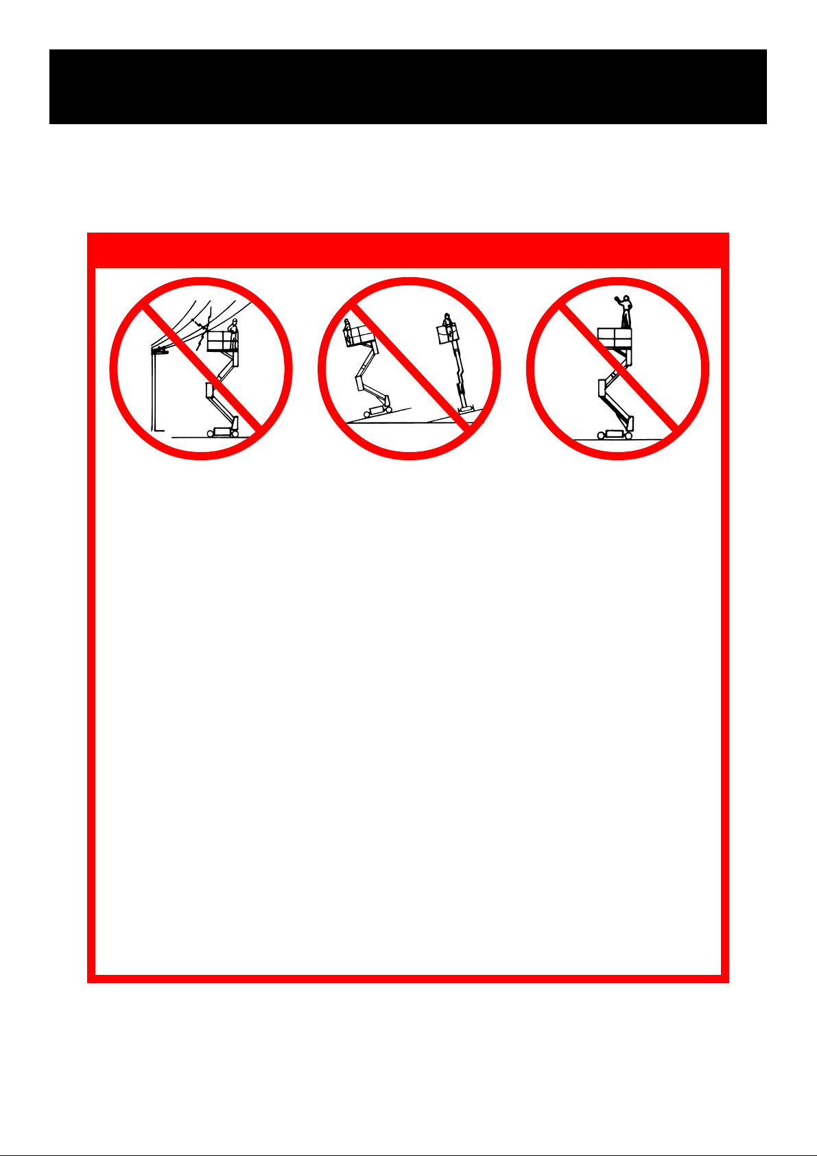
NEVER operate the machine
within ten feet of power lines.
THIS MACHINE IS NOT INSULATED.
NEVER operate the machine when wind speed is greater than 12.5 m/s (28 mph).
NEVER excede the maximum lateral force of 400 N (90 lbs.).
NEVER operate the machine without first surveying the work area for surface hazards such as
holes, drop-offs, bumps and debris before operating machine.
NEVER operate the machine if all guardrails are not properly in place and secured with all
fasteners properly torqued.
SECURE gate across entrance after mounting platform.
NEVER use ladders or scaffolding on the platform.
NEVER attach overhanging loads or increase platform size.
LOOK up, down and around for overhead obstructions and electrical conductors.
DISTRIBUTE all loads evenly on the platform. See the back cover for maximum platform load.
NEVER use damaged equipment. (Contact UpRight for instructions, see phone number on back cover.)
NEVER change operating or safety systems.
INSPECT the machine thoroughly for cracked welds, loose hardware, hydraulic leaks, damaged
control cable, loose wire connections and wheel bolts.
NEVER climb down elevating assembly with the platform elevated.
NEVER perform service on machine while platform is elevated without blocking elevating assembly.
NEVER recharge batteries near sparks or open flame; batteries that are being charged emit
highly explosive hydrogen gas.
AFTER USE secure the work platform against unauthorized use by turning key switch off and
removing key.
NEVER replace any component or part with anything other than original UpRight replacement
parts without the manufacturer's consent.
NEVER elevate the platform or
drive the machine while elevated unless the machine is
on a firm level surface.
NEVER sit, stand or climb on
guardrail or midrail.
3
Introduction
This manual covers SL26/30 Rough Terrain Work
Platforms. This manual must be stored on the
machine at all times.
Pre-Operation and Safety
Inspection
Read, understand and follow all safety rules
and operating instructions and then perform
the following steps each day before use.
1. Remove module covers and inspect for damage, oil leaks or missing parts.
2. Check the level of the hydraulic oil with the
platform fully lowered. Oil should be visible in
the sight gauge. Add hydraulic oil, if necessary
(see Specifications, back cover).
3. Check that the fluid level in the battery is
correct (see Battery Maintenance, page 8).
4. Carefully inspect the entire work platform for
damage such as cracked welds or structural
members, loose or missing parts, oil leaks,
damaged cables or hoses, loose connections
and tyre damage.
5. Check that all guardrails are securely in place
with all fasteners properly torqued.
6. Pull out on the Chassis Emergency Stop Button
to turn the switch ON.
Engine Inspection
1. Check fuel supply.
2. Check engine oil level with dipstick.
3. While the engine is cool check the radiator
coolant level. DO NOT check coolant when the
engine or radiator is hot.
System Function Inspection
STAND CLEAR of the work platform while
performing the following checks.
Before operating the work platform survey
the work area for surface hazards such as
holes, drop-offs, bumps and debris.
Check in ALL directions, including above
the work platform, for obstructions and
electrical conductors.
Protect control console cable from possible
damage while performing checks.
1. Unhook Controller from front guardrail. Firmly
grasp Controller hanger in such a manner that
the Interlock Lever can be depressed, while
performing the following checks from the
ground.
2. Pull Controller Emergency Stop Button out to
ON position.
3. Turn Controller Key Switch fully clockwise to
start the engine, releasing the key once the
engine starts.
Note: If the engine is cold, turn the key fully
counterclockwise and hold for 6 seconds to
engage the glow plugs.
4. Place Drive/Lift Switch in DRIVE position.
5. With the Speed Range Switch first in HIGH
TORQUE and then in HIGH SPEED actuate the
Interlock Lever and slowly push the Control
Lever to FORWARD then REVERSE positions
to check for speed and directional control. The
farther you push or pull the Control Lever from
centre the faster the machine will travel.
6. Push Steering Switch RIGHT then LEFT to
check for steering control.
7. Rehook Controller on front guardrail.
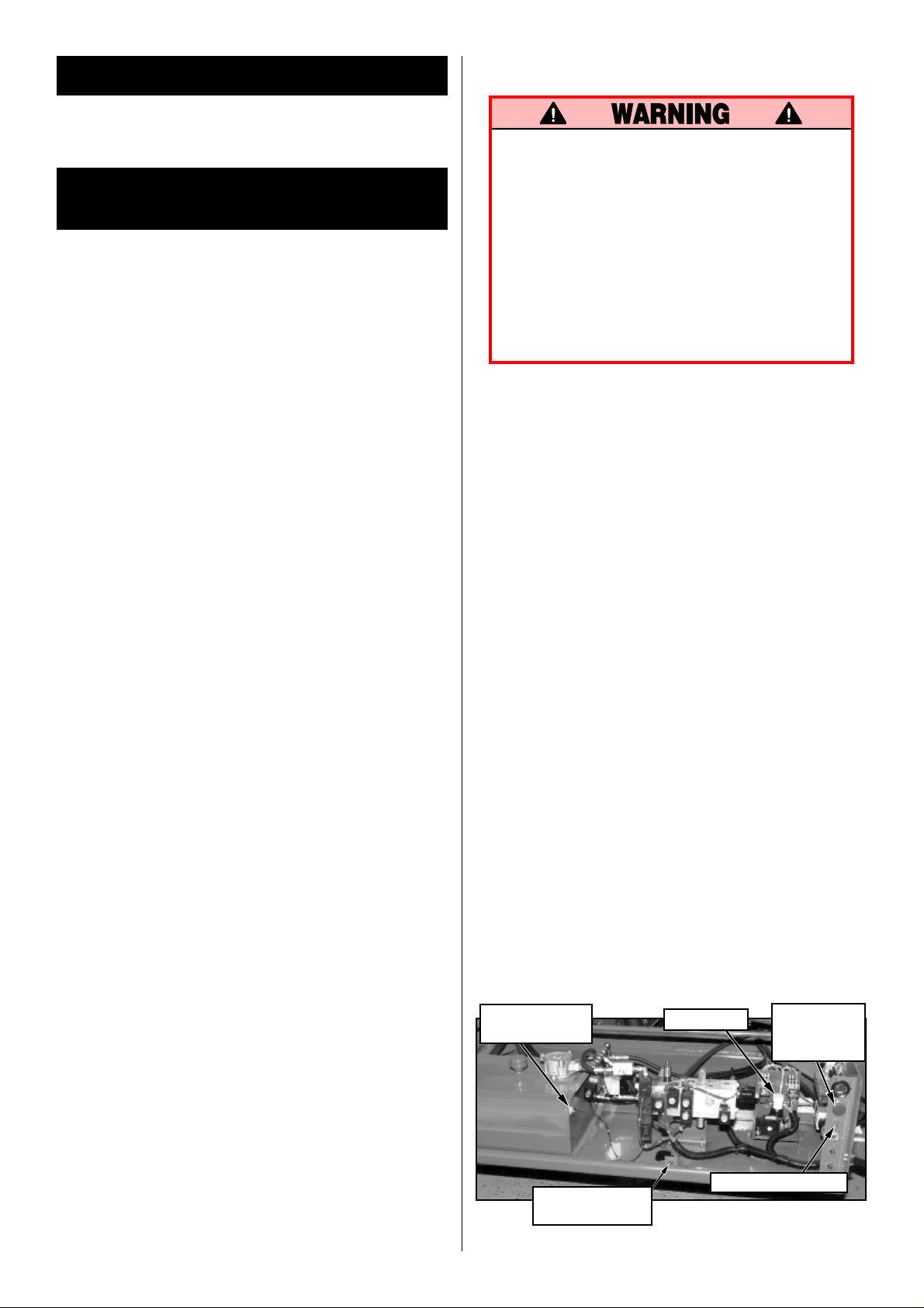
Hydraulic Tank
Sight Gauge
Emergency
Lowering Switch
Figure 1: Control Module, Chassis Left Side
4
Tilt Sensor
Chassis Lift Switch
Chassis
Emergency
Stop Buttton
8. Push Chassis Lift Switch to UP position and
elevate platform while pushing the Tilt Sensor
off of level. The platform should only elevate
about .3 m (1 ft.) and the Tilt Alarm should
sound. If the platform continues to elevate and/
or there is no alarm STOP and remove the
machine from service until repaired.
9. Release the Tilt Sensor and fully elevate platform.
10. Visually inspect the elevating assembly, lift
cylinder, cables and hoses for damage or
erratic operation. Check for missing or loose
parts.
11. Lower the platform partially by pushing Chassis
Lift Switch to DOWN, and check operation of
the audible lowering alarm.
12. Push down on the Chassis Emergency Lowering Switch to check for proper operation. Once
the platform is fully lowered, release the switch.
13. With only one Emergency Stop Button pushed
down, in the OFF position, operate a control to
verify that the Emergency Stop Switch is functioning. Repeat the test with only the other
Emergency Stop Switch OFF. If any function
operates with either Emergency Stop Switch in
the OFF position STOP and remove the machine from service until it is repaired.
14. Close and secure module covers.
15. Turn the Controller Key Switch counterclockwise to OFF.
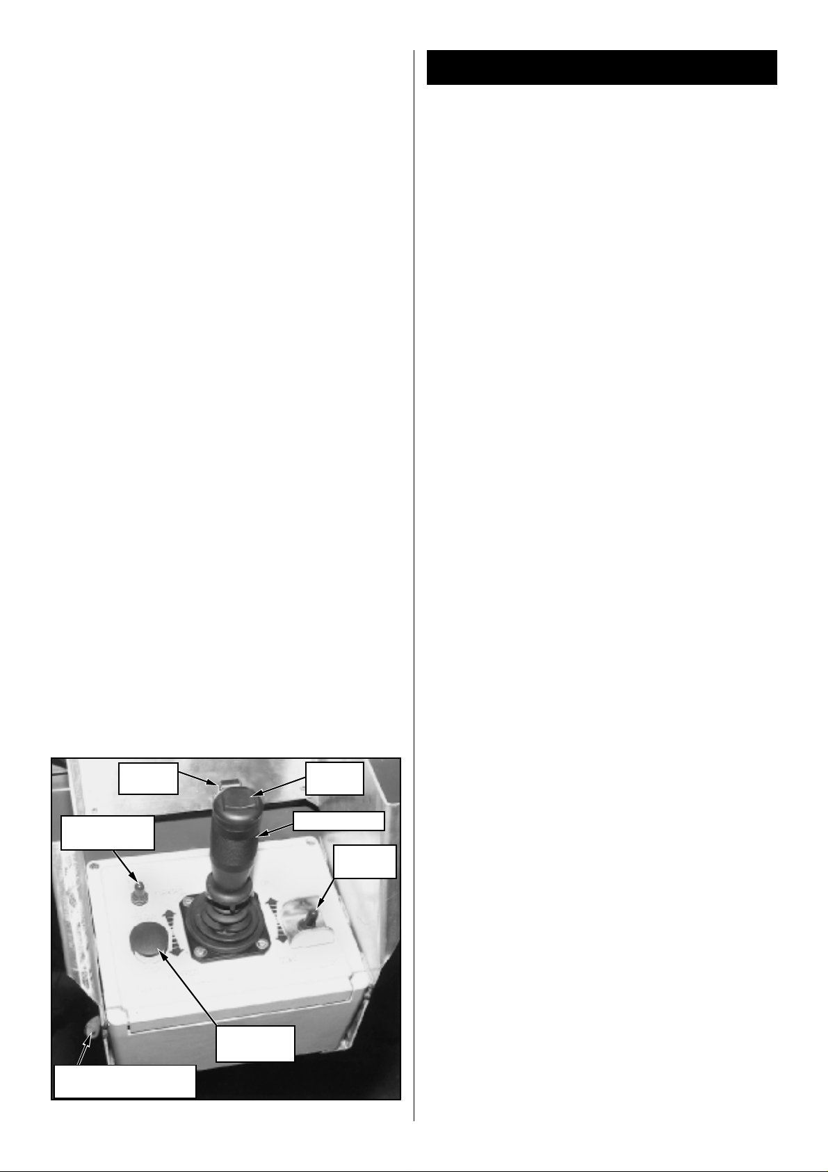
Interlock
Lever
Steering
Switch
Operation
Before operating work platform, ensure that the
pre-operation and safety inspection has been
completed, any deficiencies have been corrected
and the operator has been thoroughly trained on
this machine.
Travel With Platform Lowered
1. Verify Chassis Emergency Stop Switch is in the
ON position, pull the button out.
2. After mounting platform, close and latch gate.
Check that guardrails are in position and properly assembled with fasteners properly torqued.
3. Check that route is clear of persons, obstructions, holes and drop-offs and is capable of
supporting the wheel loads.
4. Check clearances above, below and to the
sides of the platform.
5. Pull Controller Emergency Stop Button out to
ON position.
6. Turn Controller Key Switch fully clockwise to
start the engine, releasing the key once the
engine starts.
Note: If the engine is cold, turn the key fully
counterclockwise and hold for 6 seconds to
engage the glow plugs.
7. Set the Drive/Lift Speed Range Switch to HIGH
TORQUE.
8. Grasp the Control Lever so the Interlock Lever
is depressed (releasing the Interlock Lever cuts
power to Controller). Slowly push or pull the
Control Lever to FORWARD or REVERSE to
travel in the desired direction. The farther you
push or pull the Control Lever from centre the
faster the machine will travel.
9. While moving, push the Drive/Lift Speed Range
Switch to HIGH SPEED for travel on level
surfaces or to HIGH TORQUE for climbing
grades or travelling in confined areas.
Steering
Speed Range
Switch
Key Switch (on right
side for Diesel Model)
Figure 2: Controller
Emergency
Stop Switch
Control Lever
Drive/Lift
Switch
Push the Steering Switch RIGHT or LEFT to turn
the wheels. Observe the tyres while maneuvering
to insure proper direction.
Note: Steering is not self-centering. Wheels
must be returned to the straight ahead position
by operating the Steering Switch.
5
Raising and Lowering The Platform
1. Position the Drive/Lift Switch to LIFT.
2. While holding the Control Lever so the Interlock
Lever is depressed, push the Control Lever
slowly to UP to raise the platform. Pushing the
Control Lever farther increases the lift speed.
3. When the work task is completed, position the
Drive/Lift Switch to LIFT and lower the platform
by pulling back on the Control Lever until the
platform is fully lowered.
Travel With Work Platform Elevated
Travel with platform elevated ONLY on firm and
level surfaces.
Note: The Work Platform will travel at reduced
speed when in the elevated position. SL30
Models will only drive while elevated when the
Platform is below 8m (26 ft.) in height.
1. Check that the route is clear of persons, obstructions, holes and drop-offs, is level and
capable of supporting the wheel loads.
2. Check clearances above, below and to the
sides of platform.
3. Position the Drive/Lift Switch to the DRIVE
position.
4. Push the Control Lever to FORWARD or
REVERSE for the desired direction of travel.
Note: If the machine quits driving and the Tilt
Alarm sounds, immediately lower the platform
and move the machine to a level location before re-elevating the platform.
After Use Each Day
1. Ensure that the platform is fully lowered.
2. Park the machine on level ground, preferably
under cover, secure against vandals, children
or unauthorized operation.
3. Turn the Key Switch to OFF and remove the
key to prevent unauthorized operation.
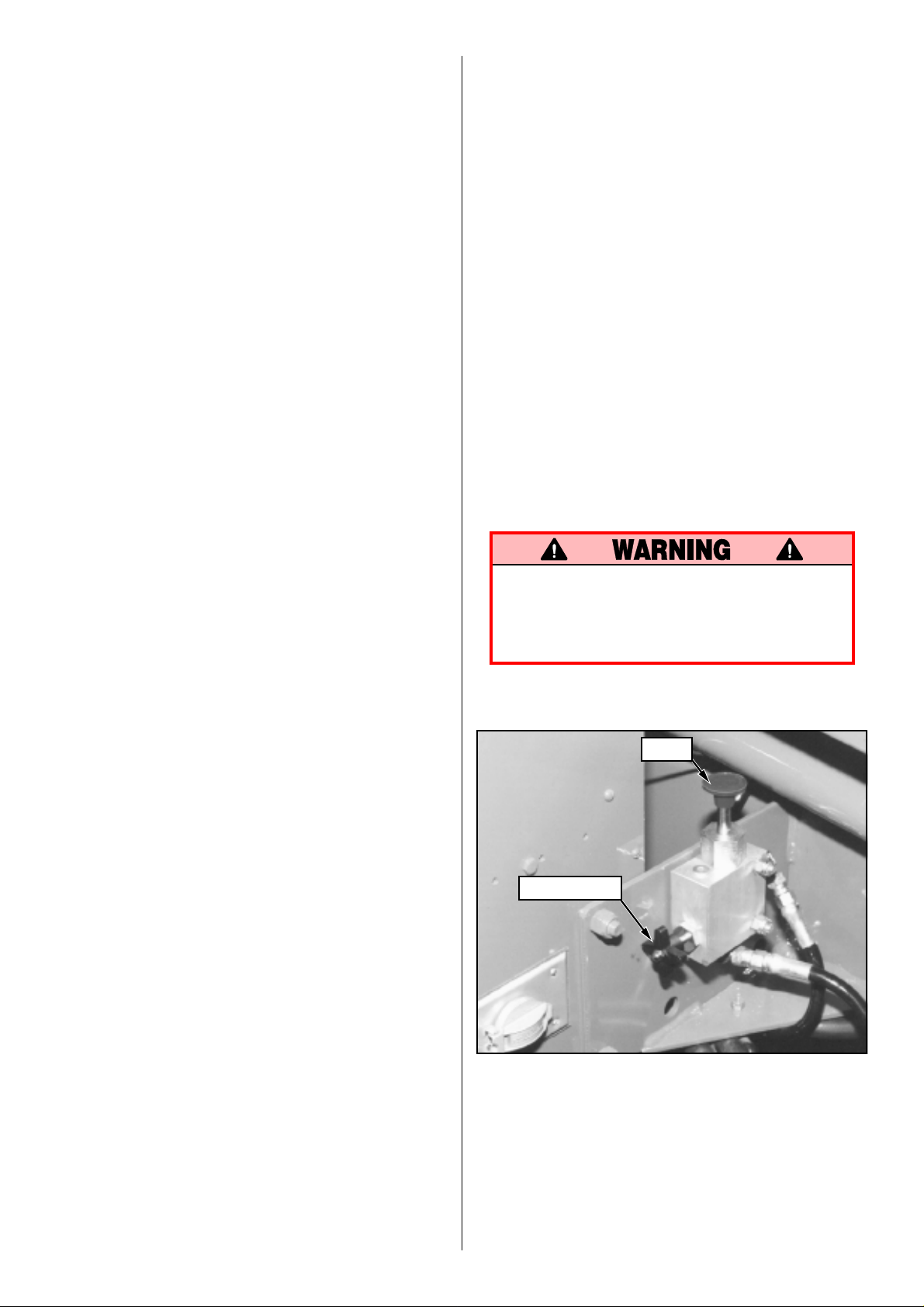
Parking Brake Release (Figure 3)
Perform the following only when the machine will
not operate under its own power and it is necessary to move the machine or when towing the
machine up a grade or winchng onto a trailer to
transport.
1. Close the needle valve by turning the knob
clockwise.
2. Pump the Brake Release Pump until the Parking
Brakes release and the wheels can be turned.
3. The machine will now roll when pushed or
pulled.
4. Be sure to open the needle valve and verify
that the Parking Brakes have e ng a ge d be f o re
the machine is operated.
Never operate work platform with the
Parking Brakes inoperative. Serious injury
or damage could result.
Never tow faster than .3 m/sec (1 ft./sec.).
Emergency Lowering
Note: The Emergency Lowering Switch is
located on the left hand side of the chassis
through the cutout in the Control Module cover.
1. Open the Emergency Lowering Valve by pushing down on the Emergency Lowering Switch.
2. Once the platform is fully lowered, release the
switch to close the Emergency Lowering Valve.
The platform will not elevate if the Emergency
Lowering Valve has not been closed.
Pump
Needle Valve
Figure 3: Brake Release Pump
6
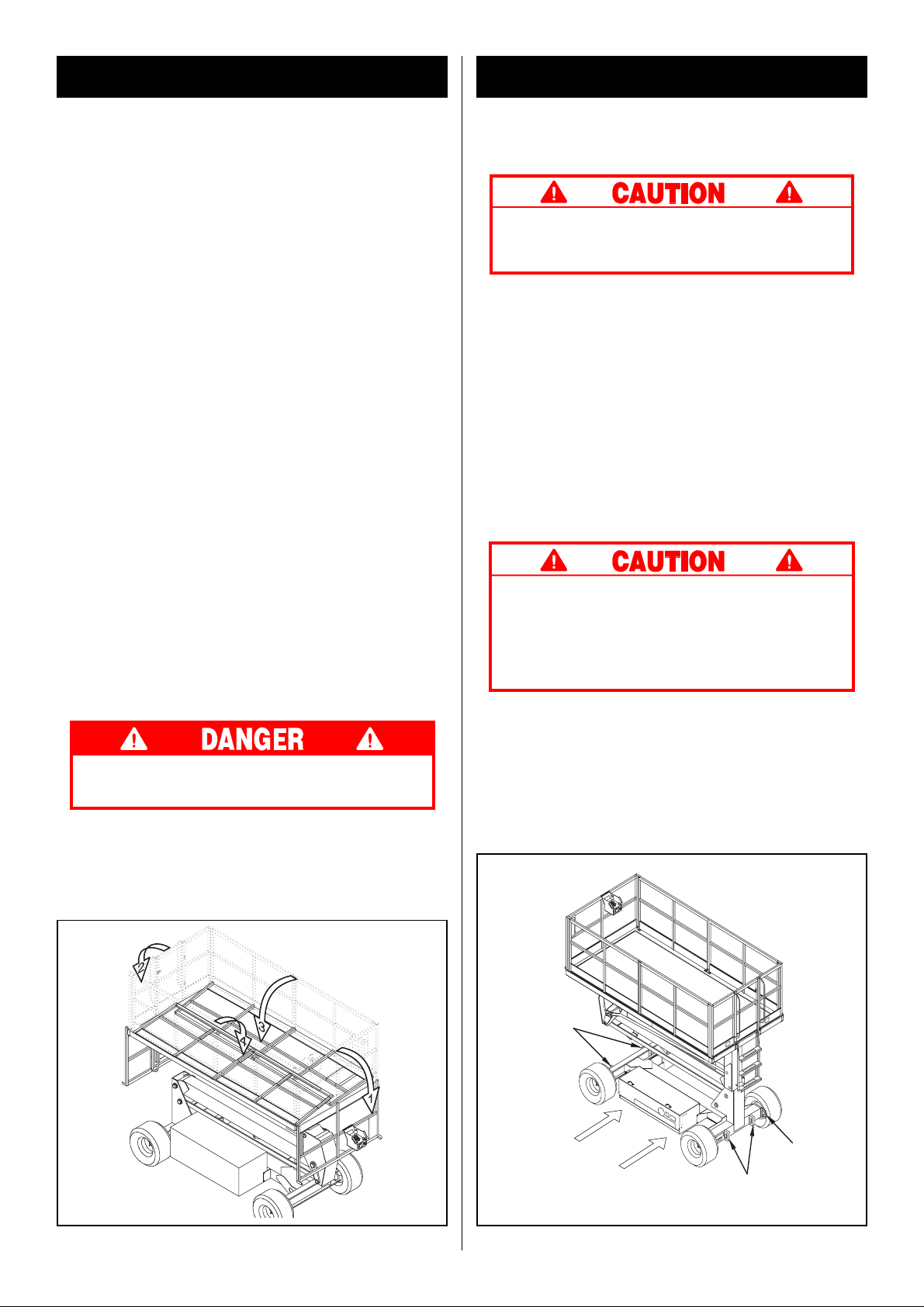
Fold Down Guardrails
Transporting Work Platform
This procedure is only for passing through doorways. Guardrails must be returned to proper
position before using the machine.
Fold Down Procedure (Figure 4)
Note: When performing the following procedures retain all fasteners.
1. Place Controller on deck.
2. Starting at the front of the Platform, remove
nuts, bolts and washers from the top of the
front guardrail. Fold the front guardrail forward
and down.
3. Hang the Controller from the front guardrail.
4. Close and latch the gate.
5. Remove nuts, bolts and washers from the top
of the rear guardrail. Fold the rear guardrail
back and down being careful to keep gate
latched at all times.
6. Fold one side guardrail in so it rests on the
deck. Repeat with other side guardrail.
Erection Procedure
1. Raise side guardrails.
2. Raise rear guardrail assembly, aligning holes
and install bolts, washers and nuts. Tighten
securely.
3. Place the Controller on the deck.
4. Raise front guardrail, aligning holes and install
bolts, washers and nuts. Tighten securely.
5. Hang Controller from front guardrail.
6. Before operating work platform check that all
fasteners are in place and properly torqued.
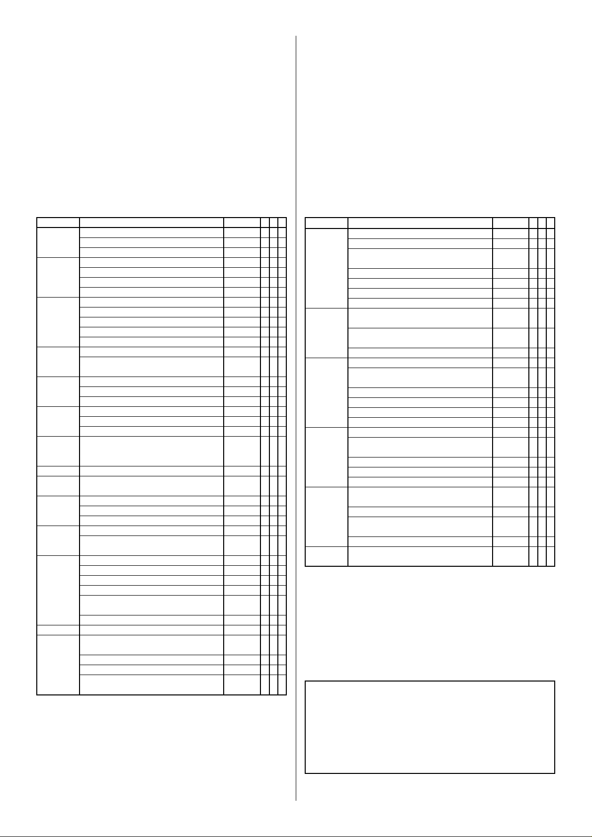
By Forklift
Note: Forklifting is for transporting only.
See specifications for weight of work platform
and be certain that forklift is of adequate
capacity to lift platform.
Forklift from side of Chassis by lifting under the
Chassis Modules (Figure 5).
By Crane
Secure straps to Chassis Lifting Lugs only (Figure 5).
By Truck
1. Manoeuvre the work platform into transport
position and chock wheels.
2. Secure the work platform to the transport
vehicle with chains or straps of adequate load
capacity attached to the chassis tie down lugs
(Figure 5).
Tie down lugs are not to be used to lift work
platform.
Over-tightening of chains or straps through
tie down lugs may result in damage to work
platform.
Before entering Platform, guardrails must
be securely fastened in their proper position.
Front Tie
Downs/
Lifting Lugs
Forklift
Rear Tie
Downs
Right Rear
Lifting Lug
(Typical)
Figure 4: Fold Down Guardrails Figure 5: Transporting Work Platform
7

Maintenance
Battery Maintenance
Never perform service on the work platform
while the platform is elevated.
Note: No normal (routine) maintenance on the
SL26/30RT should require the platform to be
raised.
Hazard of explosive gas mixture. Keep
sparks, flame, and smoking material away
from battery.
Always wear safety glasses when working
with batteries.
Battery fluid is highly corrosive. Thoroughly
rinse away any spilled fluid with clean water.
Battery Inspection and Cleaning
Check battery fluid level daily, especially if work
platform is being used in a warm, dry climate. If the
electrolyte level is lower than 10mm (
the plates, add clean, distilled water only. Use of
tap water with high mineral content will shorten
battery life.
The battery should be inspected regularly for signs
of cracks in the case, electrolyte leakage and
corrosion of the terminals. Inspect cables for worn
spots or breaks in the insulation and for broken
cable terminals.
Clean the battery when there is signs of corrosion
at the terminals or when electrolyte has overflowed
during charging. Use a baking soda solution to
clean the battery, taking care not to get the solution
inside the cells. Rinse thoroughly with clean water.
Clean battery and cable contact surfaces to a
bright metal finish whenever a cable is removed.
3
/8 in.) above
8
Routine Service
Use the following table as a guide for routine
maintenance. Inspection and maintenance shall
be performed by personnel who are trained and
familiar with mechanical and electrical procedures. Refer to the Service Manual for complete
service instructions.
Please copy this page and use the Routine Service
table as a checklist when inspecting a machine for
service.
Routine Service Table Key
Interval
Daily=each shift (every day) or every eight hours
30d=every month (30 days) or every 50 hours
3m=every 3 months or 125 hours
6m=every 6 months or 250 hours
1y=every year or 500 hours
2y=every 2 years or 1000 hours
Y=Yes/Acceptable
N=No/Not Acceptable
R=Repaired/Acceptable
COMPONENT INSPECTION OR SERVICES INTERVAL Y N R
Engine Oil Check level and condition Daily
Check for leaks Daily
Change oil & filter 100HOURS
Engine Fuel Check fuel level Daily
System Check for leaks Daily
Replace fuel filter 6M
Check air cleaner Daily
Engine Check electrolyte level Daily
Battery Check specific gravity 30D
System Clean exterior 6M
Check battery cable condition Daily
Clean terminals 6M
Engine Check coolant level (with engine cold) Daily
Coolant Replace coolant 3M
Hydraulic Oil Check oil level Daily
Change filter 6M
Drain and replace oil 2Y
Hydraulic Check for leaks Daily
System Check hose connections 30D
Check hoses for exterior wear 30D
Emergency Open the emergency lowering Daily
Hydraulic valve and check for
System serviceability
Controller Check switch operation Daily
Control Check the exterior of the cable Daily
Cable for pinching, binding or wear
Platform Check fasteners for proper torque Daily
Deck and Check welds for cracks Daily
Rails Check condition of deck Daily
Tyres Check for damage Daily
Check lug nuts/bolts, 30d
torque to 123 Nm (90 ft. lbs.)
Hydraulic Wipe clean 30D
Pump Check for leaks at mating surfaces 30D
Check for hose fitting leaks Daily
Check mounting bolts for proper torque 30D
Check the drive coupling for proper
alignment and lubricate 1Y
Lubricate pump splines 6M
Drive Motors Check for operation and leaks Daily
Steering Check hardware & fittings 6M
System for proper torque
Grease pivot pins 30D
Oil king pins 30D
Check steering cylinder for leaks & 30D
mounting bolts for proper torque
COMPONENT INSPECTION OR SERVICES INTERVAL Y N R
Elevating Inspect for structural cracks Daily
Assembly Check pivot points for wear 30D
Check mounting pin pivot bolts 30D
for proper torque
Check linkage gear for wear 6M
Check elevating arms for bending 6M
Grease linkage pins 30D
Grease linkage gear 30D
Chassis Check hoses for pinch or Daily
rubbing points
Check component mounting 6M
for proper torque
Check welds for cracks Daily
Lift Check the cylinder rod for wear 30D
Cylinder Check mounting pin pivot bolts 30D
for proper torque
Check pivot pin snap rings 30D
Check seals for leaks 30D
Inspect pivot points for wear 30D
Check fittings for proper torque 30 D
Axle Check the cylinder rod for wear 30D
Cylinder Check mounting pin pivot bolts 30D
for proper torque
Check seals for leaks 30D
Inspect pivot points for wear 30D
Check fittings for proper torque 30 D
Entire Check for and repair Daily
Unit collision damage
Check fasteners for proper torque 3M
Check for corrosion-remove 6M
and repaint
Lubricate 30D
Labels Check for peeling, missing, or unreadable Daily
labels & replace
Service Report
Date: ______________
Owner: ________________________________
Model No: ____________Serial No: _________
Serviced By: ____________________________
Service Interval: _________________________
9

ITEM
Specifications*
SL26RT
SL30RT
Platform Size
Standard
w/ Extension
Max. Platform Capacity
Standard
w/ Extension
on Extension
Max. No. of occupants
Standard
on Extension
Height
Working Height
Max. Platform Height
Min. Platform Height
Dimensions
Weight
Overall Width
Overall Height
Overall Length
Driveable Height
Surface Speed
Platform Lowered
Platform Raised
System Voltage
Hydraulic Tank Capacity
Maximum Hydraulic System
Pressure
Hydraulic Fluid
Normal Use (> 0° C [32 °F])
Low Temp. Use
(-23° to 0 °C [-10° to 32 °F])
Lift System
Lift Speed
Power Source
Drive Control
Control System
Horizontal Drive
Tyres
Parking Brakes
Turning Radius (inside)
Maximum Gradeability
Wheel Base
Guardrails
Toeboard
(Inside Toeboards)
1.71 m x 3.59 m [67.5 in. x 141.5 in.]
1. 71m x4.6 1m [67.5 in. x 181.5 in.]
680kg [1500 lbs.]
680kg [1500 lbs.]
110 kg [250 lbs.]
5 people
1 person
9.75 m [32 ft.]
7.93 m [26 ft.]
1.5 m [59 in.]
Diesel: 2,531 kg [5,580 lbs.]
2.13 m [84 in.]
2.60 m [102.5 in.]
3.79 m [149 in.]
7.93 m [26 ft.]
0 to 5.0 km/h [0 to 3.1 mph]
0 to .8 km/h [0 to .5 mph]
12 Volt DC
45.5 L [12 gal.]
172 bar [2500 psi]
ISO #46
5W-20 Motor Oil
One Single Stage Lift Cylinder
Raise, 21 sec./Lower, 32 sec.
18 HP Kubota Diesel, 3 Cylinder, Water Cooled Engine
Proportional
Joystick Controller with Interlock Lever and Thumb Rocker
Steering, Toggle Selector and Emergency Stop Switches
Four Wheel, Hydraulic Motors
26 x 12.00 - 12 NHS Super Terra-grip, Foam Filled
Two, Spring Applied, Hydraulic Release, Multiple Disc
3.96 m [13 ft.]
19° [35%]
2.54 m [100 in.]
1.11 m [43.5 in.] high, Fold Down with Gate
152 mm [6 in.] High
1.71 m x 4.22m [67.5 in. x 166.25 in.]
N/A
590 kg [1300 lbs.]
N/A
N/A
5 people
N/A
10.97 m [36 ft.]
9.14 m [30 ft.]
1.5 m [59 in.]
Diesel: 2,644 kg [5,830 lbs.]
2.13 m [84 in.]
2.60 m [102.5 in.]
4.39 m [173 in.]
7.93 m [26 ft.]
0 to 5.0 km/h [0 to 3.1 mph]
0 to .8 km/h [0 to .5 mph]
12 Volt DC
45.5 L [12 gal.]
172 bar [2500 psi]
ISO #46
5W-20 Motor Oil
One Single Stage Lift Cylinder
Raise, 24 sec./Lower, 36 sec.
18 HP Kubota Diesel, 3 Cylinder, Water Cooled Engine
Proportional
Joystick Controller with Interlock Lever and Thumb Rocker
Steering, Toggle Selector and Emergency Stop Switches
Four Wheel, Hydraulic Motors
26 x 12.00 - 12 NHS Super Terra-grip, Foam Filled
Two, Spring Applied, Hydraulic Release, Multiple Disc
3.96 m [13 ft.]
19° [35%]
2.54 m [100 in.]
1.11 m [43.5 in.] high, Fold Down with Gate
152 mm [6 in.] High
* Specifications subject to change without notice.
Refer to Service Manual for complete parts and service information.
10
Version Française
CONSIGNES DE SÉCURITÉ
NE JAMAIS UTILISER la ma-
chine à moins de trois mètres
des lignes électriques. CETTE
MACHINE N’EST PAS
ISOLÉE.
NE JAMAIS utiliser la machine lorsque la vitesse du vent est supérieure à 12,5 m/s.
NE JAMAIS dépasser la force latérale maximum de 400 N (90 livres).
NE JAMAIS utiliser la machine sans avoir au préalable examiné la zone de travail en
recherchant les dangers de surface, comme les trous, les pentes, les bosses et les débris.
NE JAMAIS utiliser la machine si les garde-corps ne sont pas correctement en place et bloqués
avec des vis bien serrées.
REFERMER le portillon après être monté sur la plate-forme.
NE JAMAIS utiliser d’échelles ou d’échafaudages sur la plate-forme.
NE JAMAIS fixer de charge en surplomb ni élargir la plate-forme.
REGARDER en haut, en bas et tout autour en cherchant les fils électriques et les obstructions en hauteur
RÉPARTIR les charges sur plate-forme uniformément. Voir au dos du manuel la charge maximum
de la plate-forme.
NE JAMAIS utiliser d’équipement endommagé (contacter UpRight pour des instructions. Voir le
numéro d’appel gratuit au dos du manuel).
NE JAMAIS changer le système de fonctionnement ou de sécurité.
INSPECTER soigneusement la machine en recherchant les soudures fissurées, la visserie
desserrée, les fuites hydrauliques, les câbles de commande endommagés, les connexions
desserrées et les boulons de roues desserrés.
NE JAMAIS descendre en escaladant l’ensemble élévateur avec la plate-forme levée.
NE JAMAIS effectuer d’entretien sur la machine pendant que la plate-forme est levée sans
bloquer l’ensemble élévateur.
NE JAMAIS recharger les batteries près d’étincelles ou de flammes nues; les batteries qui sont
en cours de chargement émettent de l’hydrogène hautement explosif.
APRÈS USAGE, s’assurer que la plate-forme ne puisse pas être utilisée de manière non autorisée
en tournant la clé de contact sur arrêt et en enlevant la clé.
NE JAMAIS remplacer sans l’accord du fabricant des composants ou des pièces par des pièces
autres que des pièces de rechange originales UpRight.
NE JAMAIS élever la plateforme ou conduire la machine
levée à moins que la machine
ne soit sur une surface ferme
et horizontale.
NE JAMAIS s’asseoir, se tenir
debout ou monter sur le gardecorps.
11
 Loading...