

Page 1
MB20N/26
Operator Manual
This first section of the Operator manual is the English language version.
Betriebsanleitung
Im zweiten Abschnitt dieser Betriebsanleitung finden Sie die Deutsche Version.
Manuel Utilisateur
èLa troisième section de ce manuel est la version en langue Française.
Manual del Usuario
El apartado cuarto de este manual del usuario corresponde a la versión en Españo.
Manuale d’Uso
La quinta sezione di questo manuale d'uso è la versione in lingua Italiana.
(EN) Manual part number 501375-001 for serial numbers MB20N-132/MB26-
245 to current.
(DE) Bestellnummer 501375-001 ab Seriennummer MB20N-132/MB26-245
fortlaufend.
(FR) Manuel Pièce numéro 501375-001 pour numéro série MB20N-132/
MB26-245 jusqu'au numéro courant.
(ES) El número de referencia para el manual es el 501375-001 para la
números de serie del MB20N-132/MB26-245 hasta el actual.
(IT) Manuale Ricambi Numero 501375-001 per Numeri di Serie da MB20N-
132/MB26-245 all’attuale.
Feb 08
Page 2

NOTES:
Page 3

MB 20N/26
Serial Numbers MB20N 132 - Current
MB26 246 - Current
ENGLISH
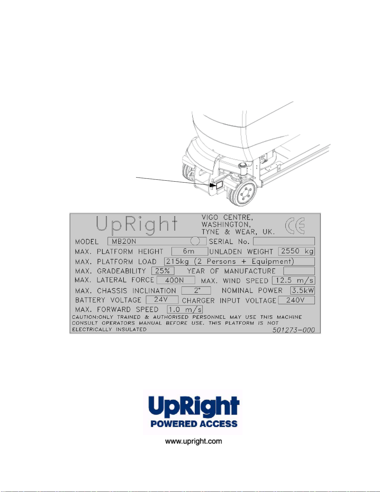
When contacting UpRight Powered Access for
service or parts information, be sure to include
the MODEL and SERIAL NUMBERS from the
equipment nameplate. Should the nameplate be
missing, the SERIAL NUMBER is also stamped
on top of the chassis above the front axle pivot.
Nameplate
The Work Platform Nameplate is located
externally at the FRONT of the chassis
When contacting UpRight for service or parts information, sure to include
the MODEL and SERIAL NUMBERS from the equipment nameplate.
The MB20N/26 work platform meets and exceeds the requirements of both:
prEn280:2001 and ANSI A92.5 (1999)
Page 4

NOTES:
Page 5
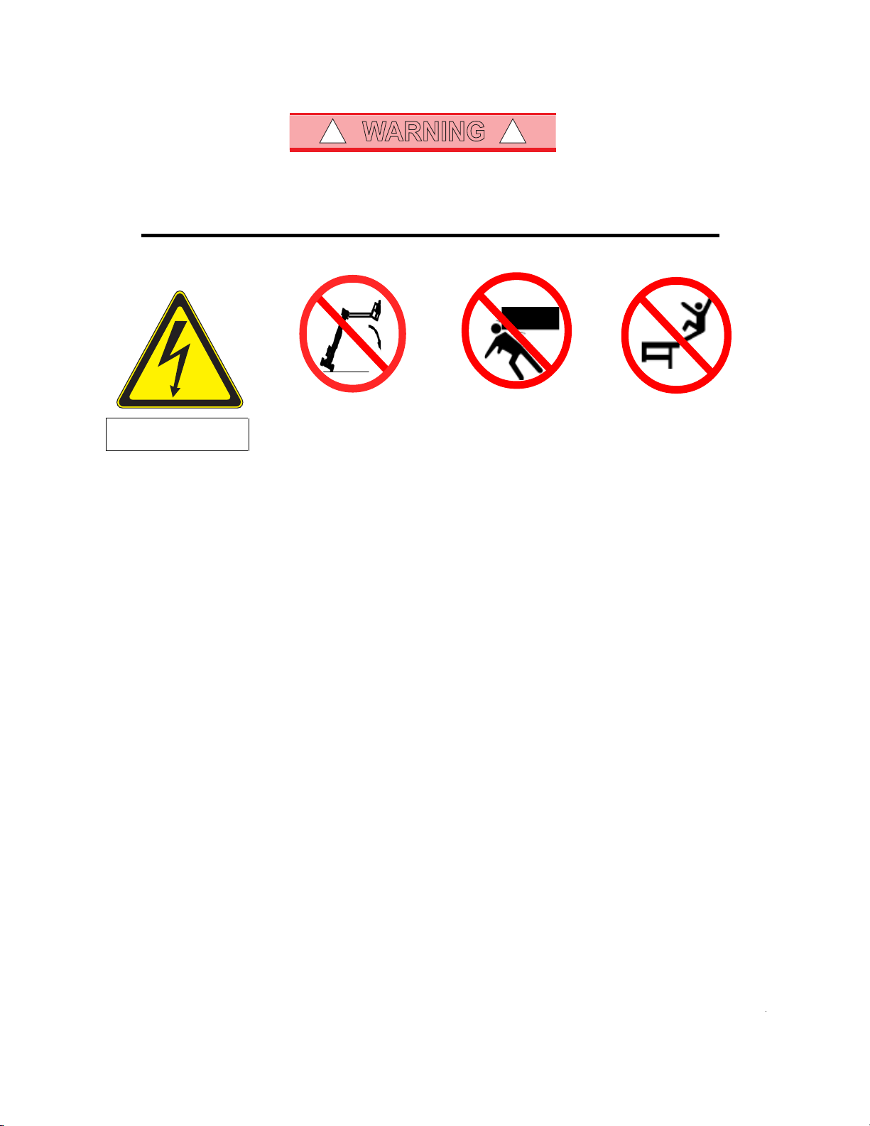
WARNING
! !
All personnel shall carefully read, understand and follow all safety rules and operating instructions
before operating or performing maintenance on any UpRight Powered Access aerial work platform.
Safety Rules
Electrocution Hazard Tip Over Hazard Collision Hazard Fall Hazard
THIS MACHINE IS NOT
INSULATED!
USE OF THE AERIAL WORK PLATFORM: This aerial work platform is intended to lift persons and his tools as well as the material used
for the job. It is designed for repair and assembly jobs and assignments at overhead workplaces (ceilings, cranes, roof structures,
buildings etc.). All other uses of the aerial work platform are prohibited!
THIS AERIAL WORK PLATFORM IS NOT INSULATED! For this reason it is imperative to keep a safe distance from live parts of
electrical equipment!
Exceeding the specified permissible maximum load is prohibited! See "Specifications - Platform Capacity" for details.
The use and operation of the aerial work platform as a lifting tool or a crane is prohibited!
NEVER exceed the manual force allowed for this machine. See “Manual Force” on page 2 for details.
DISTRIBUTE all platform loads evenly on the platform.
NEVER operate the machine without first surveying the work area for surface hazards such as holes, drop-offs, bumps, curbs, or debris;
and avoiding them.
OPERATE machine only on surfaces capable of supporting wheel loads.
NEVER operate the machine when wind speeds exceed this machine’s wind rating. See “Beaufort Scale” on page 1 for details.
NEVER attach notice boards etc. to the platform, as this will increase wind loading.
IN CASE OF EMERGENCY push EMERGENCY STOP switch to deactivate all powered functions.
IF ALARM SOUNDS while platform is elevated, STOP, carefully lower platform. Move machine to a firm, level surface.
Climbing up the railing of the platform, standing on or stepping to or from the platform onto buildings, steel or prefabricated concrete
structures, etc. is prohibited!
Dismantling the entry gate or other railing components is prohibited! Always make certain that the entry gate is closed and securely
locked!
It is prohibited to keep the entry gate in an open position when the platform is raised!
To extend the height or the range by placing of ladders, scaffolds or similar devices on the platform is prohibited!
NEVER perform service on machine while platform is elevated without blocking elevating assembly.
INSPECT the machine thoroughly for cracked welds, loose or missing hardware, hydraulic leaks, loose wire connections, and damaged
cables or hoses before using.
VERIFY that all labels are in place and legible before using.
NEVER use a machine that is damaged, not functioning properly, or has damaged or missing labels.
To bypass any safety equipment is prohibited and presents a danger for the persons on the aerial work platform and in its working range.
NEVER charge batteries near sparks or open flame. Charging batteries emit explosive hydrogen gas.
Modifications to the aerial work platform are prohibited or permissible only at the approval by
AFTER USE, secure the work platform from unauthorized use by turning the keyswitch off and removing key.
The driving of MEWP’s on the public highway is subject to Regulations made under the Road Traffic Acts.
NEVER elevate the platform or drive
the machine while elevated unless
the machine is on a firm, level
surface.
NEVER position the platform
without first checking for overhead
obstructions or other hazards.
UpRight Powered Access
NEVER climb, stand, or sit on
platform guardrails or midrail.
.
Page 6

1. I
NTRODUCTION
Figure 1. Manual Storage Information 1
S
PECIAL INFORMATION
S
2. G
ENERAL
PECIAL LIMITATIONS
M
ANUAL FORCE
P
LATFORM CAPACITY
B
EAUFORT SCALE
D
ESCRIPTION
Figure 2. Work Platform 3
3. S
AFETY INSPECTION
Figure 3. Battery Fill Button & Valve 4
Figure 4. Lower Control Panel 4
Figure 5. Joystick and Tilt Sensor 6
4. O
PERATION OF THE PLATFORM CONTROLS
U
PPER CONTROL PANEL
Figure 6. Upper Control Panel 7
C
ONTROL FUNCTIONS
Table 1. Platform Controls and Indicators 8
L
OWER CONTROL PANEL
Table 2. Chassis Controls and Indicators 9
Figure 7. Lower Control Panel 9
T
YPICAL OPERATION
C
ONTROLS AND INDICATORS
E
LEVATING
T
RAVEL WITH WORK PLATFORM LOWERED
T
RAVEL WITH WORK PLATFORM ELEVATED
E
MERGENCY
E
MERGENCY
& L
S
ITUATIONS
L
OWERING (BY HAND
OWERING THE
Figure 8. Emergency Lowering - Mast Valve 12
Figure 9. Emergency Lowering - Jib Valve 12
5. T
RANSPORTATION
M
ACHINE
W
EIGHTS
Figure 10. Lifting by Forklift 13
L
IFTING BY CRANE
Figure 11. Lifting by Crane 14
T
RANSPORT BY TRUCK
Figure 12. Securing the platform 15
T
OWING
& W
INCHING VALVES
Figure 13. Valve Block-Towing Valves 16
6. A
FTER USE
& S
TORAGE
A
FTER USE EACH DAY
H
OUR
M
ETER
L
ONG-TERM STORAGE
P
RESERVATION
Figure 14. Battery Disconnect 17
B
7. S
PECIFICATIONS
ATTERIES
D
AILY
M
AINTENANCE
C
MB20N 20
C
ONTENTS
P
W
ORK PLATFORM
11
)
12
HECKLIST
Daily Maintenance Checklist 19
MB26
21
Contents
AGE NUMBER
1
1
1
1
2
2
2
3
7
7
8
9
9
10
10
11
11
13
13
14
15
15
17
17
17
17
17
18
19
Page 7
1. I
This Operation manual is designed to provide instructions and illustrations for the safe
Figure 1: Manual Storage Information
structures outside the work platform.The maximum allowable manual force is limited to
D A N G E R
!
!
W A R N I N G
!
!
C A U T I O N
!
!
D A N G E R
!
!
NTRODUCTION
Indicates an imminently hazardous situation which, if not
avoided, will result in severe injury or death.
1 INTRODUCTION
use and operation of the MB20N & MB26 Work Platform manufactured by Upright
Powered Access Ltd.
The manual MUST be stored in the
box provided in the machine cage,
AT ALL TIMES.
S
PECIAL INFORMATION
Throughout this manual the users attention is drawn to these special warning boxes:
Indicates a potentially hazardous situation which, if not avoided,
could result in severe injury or death.
Indicates a potentially hazardous situation which, if not avoided,
may result in minor or moderate injury.
S
PECIAL LIMITATIONS
The purpose of this machine is to provide fast and safe access to difficult to reach
areas.
Refer to the Specification section for the machines access limitations.
Travel with the platform raised is limited to creep speed range.
M
ANUAL FORCE
Manual force is the force applied by the occupants to objects such as walls or other
200 N (45 lbs.) of force per occupant, with a maximum of 400 N (90 lbs.)
DO NOT exceed the maximum manual force.
NEVER exceed the platform capacity.
Page 1
Page 8
2
DANGER
!
!
DANGER
!
!
DANGER
!
!
G
ENERAL
B
EAUFORT
R
ATING
3 3,4~5,4 12,25~19,411.5~17.75 7.5~12.0
4 5,4~8,0 19,4~28,817.75~26.25 12.0~18
5 8,0~10,8 28,8~38,9 26.25~35.5 18~24.25
6 10,8~13,9 38,9~50,0 35.5~45.5 24.5~31
7 13,9~17,2 50,0~61,9 45.5~56.5 31.~38.5
D
ESCRIPTION
P
LATFORM
The Platform is designed to travel with safe working load (SWL) including work tools to
an upper limit of 215 kg (475 lbs).
B
EAUFORT
Never operate the machine when wind speeds exceed 12.5m/s (28 m.p.h.)
[Beaufort scale 6].
M/S KM/H FT./S M.P.H
C
S
W
IND SPEED
APACITY
CALE
G
.
Papers and thin branches move.
Flags wave.
Dust is raised, paper whirls up, and small branches
sway.
Shrubs with leaves start swaying.
Wave crests are apparent in ponds or swamps.
Tree branches move.
Power lines whistle. It is difficult to open an umbrella.
Whole trees sway.
It is difficult to walk against the wind.
ROUND CONDITIONS
2. G
ENERAL
DO NOT use on soft ground or on slopes greater than 2 degrees.
The work platform is NOT intended for use on uneven or rough
terrain.
ONLY operate this machine on FIRM and LEVEL ground.
DO NOT use the lifting mechanism to raise or lower goods or persons
except within the cage and subject to the specified weight limitations.
D
ESCRIPTION
The MB20/26 are self propelled, fast acting aerial work platforms, designed to raise
two operators with hand tools to a platform floor height of 6.00m and 7.76m
respectively. The accessible height is approximately 2.00m above these figures.
The unit offers the ability to reach over obstacles but must be used on firm and level
ground at all times.
DO NOT enter the platform from any structure, rack or other platform.
Page 2
Page 9
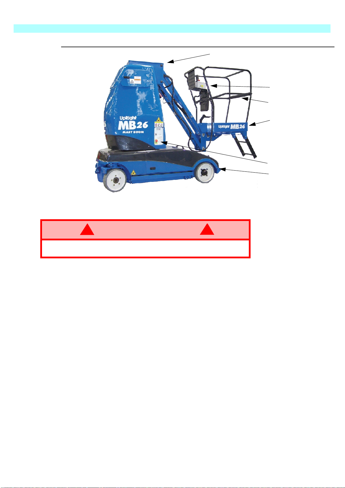
3
Work Platform
WARNING
!
!
Elevating Assembly
S
AFETY INSPECTION
Figure 2:
Platform Controller
Safety Drop-bar
Platform
Chassis Controls
Chassis
3. S
DO NOT use the work platform without safety drop-bar in place and
with the safety harness fitted.
AFETY INSPECTION
This Safety Inspection shall be carried out by the owner immediately prior to
transporting this machine.
This Safety Inspection shall also be carried out by the user prior to use each day.
The procedure is to carry out the following 14 checks in order as follows.
1.Remove the rear chassis covers by means of the two top twist-locks and the two liftand-turn catches at the sides. The cover is removed by sliding it backwards and
upwards. Use the central handle provided.
2.Ensure that the mast and jib are fully lowered. Remove the hydraulic oil filler cap and
check that the hydraulic oil level is correct. Oil should be visible on the dip stick. Top
up as necessary using hydraulic oil Viscosity Grade ISO 46.
3.Inspect the chassis area for oil leaks, loose parts, frayed cables and hoses and
structural damage etc. Check that all cable connections to the solenoid valves are
intact.
Page 3
Page 10
3
CAUTION
!
!
S
AFETY INSPECTION
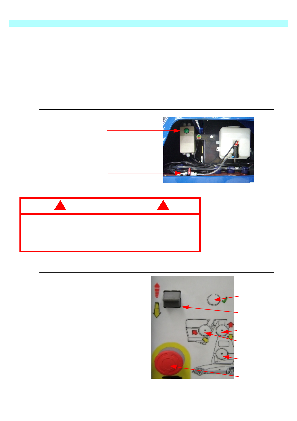
4.Open the Inspection hatches on both sides of the upper mast cover. Check that the AC
mains cable is disconnected from the battery charger. Check the electrolyte level in
each battery cell. Top up as necessary with distilled water only.
5.Use the automated battery top-up system fill the batteries to the correct electrolyte
level. This is done by opening the shut off valve and pressing the green fill button for
approximately 10 seconds, then re-closing the shut-off valve.
Batteries should be examined for cracks, acid leakage and terminal corrosion. Take
corrective action immediately if either check fails.
Figure 3: Battery Fill Button & Valve
Battery fill Button
Shut off Valve
In CLOSED Position
Vehicles fitted with the automated battery top-up system with shut
off valve, top up the battery cells with distilled water using the
electrolyte fill button, ensuring that the shut-off valve is open during
the fill and closed after use.
This is the only time this valve should be opened.
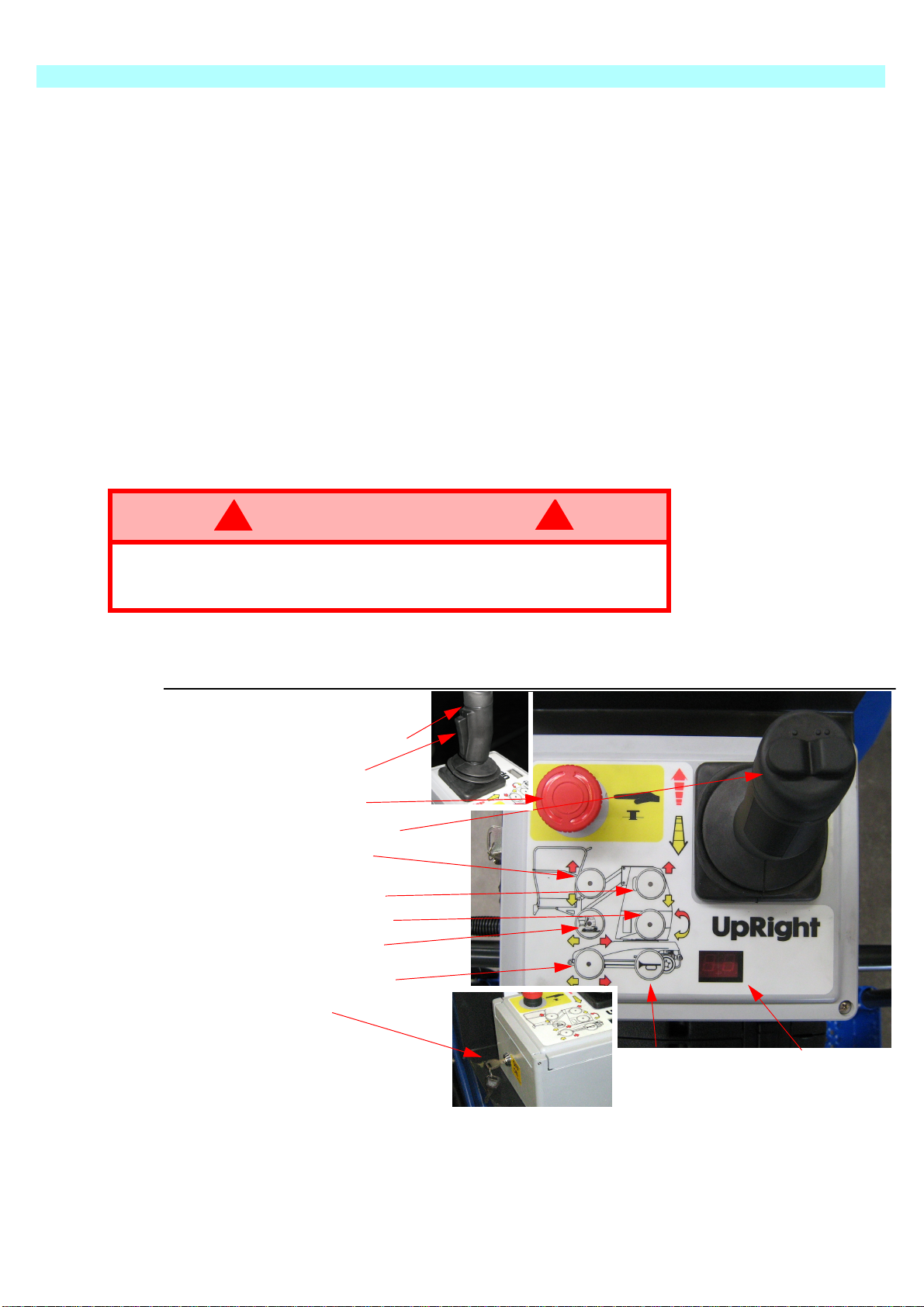
1. Enable Button
2. Analog Rocker
Figure 4: Lower Control Panel
1
2
Page 4
3. Mast Button
4. Jib Button
5. Rotate Button
6. Emergency Stop
3
4
5
6
Page 11
3
buttons on each control station are retracted; turn clockwise if necessary. Carry out the
Check jib operation by extending the jib to its fully elevated position. Check for correct
and check for correct adjustment of each lifting chain as follows. Each chain in the pair
should bear load. Use a hand held spring balance or tensiometer apply a nominal load
(approximately 10kgf.) to either chain in the pair. Apply the load about half way up the
Lowering’ decal label. Check the wear pads for damage or heavy scoring. Replace as
CAUTION
!
!
S
AFETY INSPECTION
6.Prior to operating the functions, check that the upper and lower emergency stop
following function from the Lower Control Station.
NOTE: DO NOT enter the platform at this stage.
7.
routing of the hoses and cables. Check the Emergency Lowering feature of the jib.
Ensure that when the Emergency Lowering lever/button is disengaged, the jib no
longer descends. Return the jib to its rest position using the normal Lower Control
Station.
8.Check mast chains by elevating the masts approximately 30cm above the rest
position. Check for correct routing of the energy chain. Raise the masts to full height
chain. Record the approximate deflection i.e. the offset distance from the mast.
Repeat the measurement on the adjacent chain at the same location. Chains bearing
equal load will deflect equal amounts. Carefully adjust the slack chain until the
deflections are approximately equal. Torque up the locknuts to 70 Nm.
NOTE: Apply a thin layer of grease to the lifting chains with a small paintbrush.
Over-tensioning of either lifting chain will result in unnecessary
lifting of the mast and a subsequent increase in machine stowed
height.
The function of the mast straps is to ensure that masts descend in the correct order
and more importantly, that masts cannot continue to descend if the jib or platform
meets an external obstacle. Raise the masts about 30cm. Check the external mast
clamp screws for tightness. Pull on the short length of each strap and check that they
are secure. Refer to the maintenance manual for instructions on more stringent
periodic checks on these straps.
Check the Emergency Lowering feature of the mast. The lever is located in the upper
mast over. Open the left hand battery inspection hatch and locate the ‘Emergency
necessary.
9.Elevate the jib fully. Using the Lower Control Station, turn the mast assembly through
about 90 degrees. Check the correct routing of the hoses and cables and the correct
smooth operation of the energy chain in its chassis base slide. Continue rotating
through 180 degrees in both directions. Confirm that the rotation stops are intact.
10.STANDARD PLATFORM CONTROLS Repeat the mast, jib and rotate functions from
the Upper Control Station in the platform. Check that pressing the emergency stop
button prevents subsequent operation of the joystick.
Page 5
Page 12
3
WARNING
!
!
S
AFETY INSPECTION
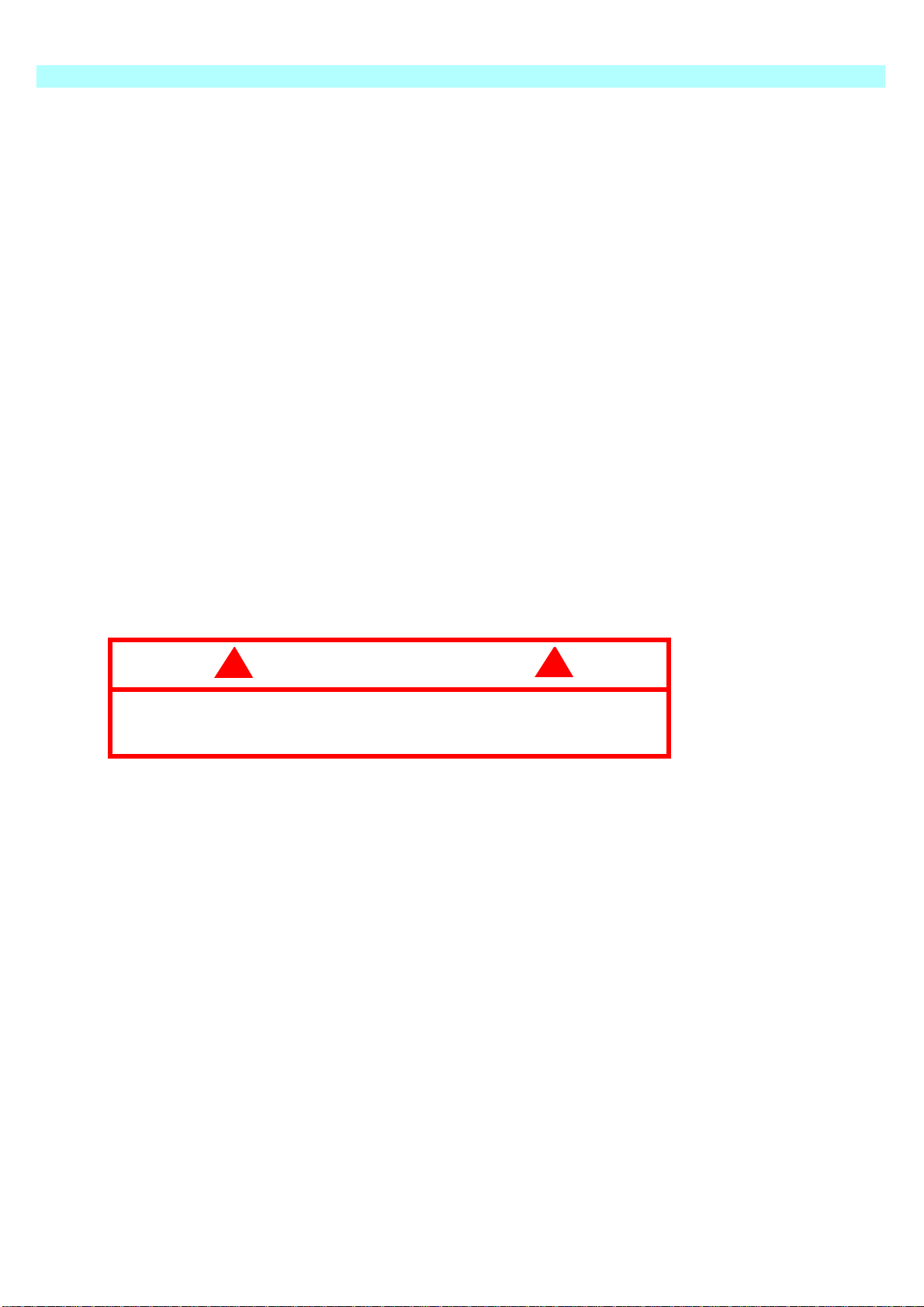
11.EMERGENCY OVER-RIDE While in the platform, ask a colleague to deflect the tilt
alarm sensor body. This sensor is located on the chassis base. The alarm will sound
and all normal function will become interrupted.
Figure 5: Joystick and Tilt Sensor
Tilt Sensor
Joystick
with Deadman Grip
12.MACHINE TRAVEL - UNELEVATED Travel functions are possible only from the
platform Upper Control Station. As with all such controls, the deadman handgrip switch
must be depressed before any function can operate.
Select Drive on the upper control panel. Pushing back and forward on the joystick
moves the machine backwards and forwards respectively.
The pothole protection will begin to retract immediately. However, full demand speed
will not be realised until the bars are fully raised. This takes about 3 seconds. Check
that the motion alarm DOES sound during travel. Check that the thumb operated
switches on the top of the joystick operates the front wheel steering.
13.MACHINE TRAVEL-ELEVATED While the masts are raised, it is possible to drive and
steer the machine at a much reduced speed. Also note that while the masts are raised,
the pothole protection bars should be fully extended and should remain extended
during slow speed motion of the machine.
The issue of reduced speed while elevated and deployment of the
pothole protection bars is crucial to the safe operation of this
machine.
The machine may not be released or operated unless these
functions operate properly.
14.FINAL PREPARATION Configure the masts and jib to the stowed position. Replace all
machine covers and secure.
NOTE: The machine is now ready for Operation or Transportation.
Page 6
Page 13
4
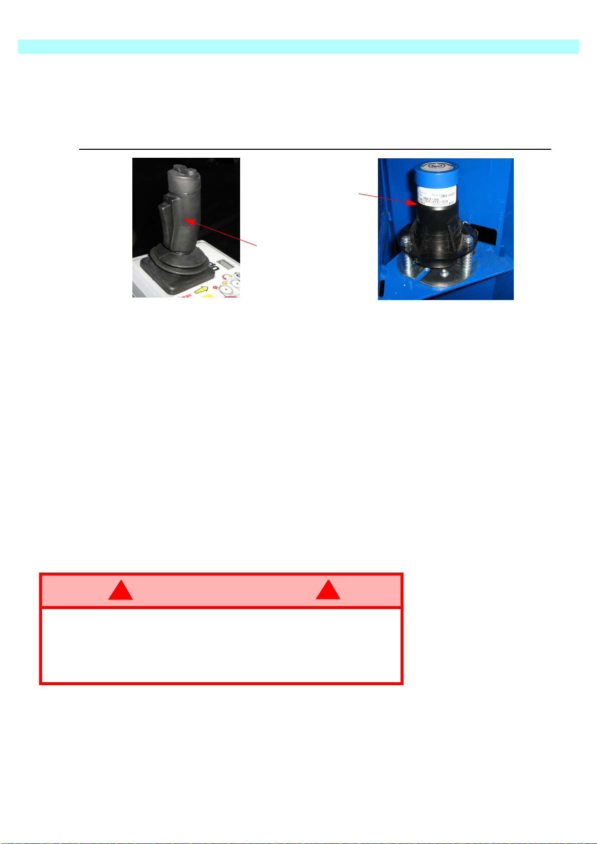
A safety Interlock Switch or ‘deadman button’ is incorporated into the Joystick. It must
be used to position
Upper Control Panel
WARNING
!
!
O
PERATION OF THE PLATFORM CONTROLS
4. O
PERATION OF THE
The primary (Upper) control box is permanently fitted to the front of the platform. It
features a multi-use joystick which provides proportional control for all the machines
functions. That includes, raising or lowering the mast, raising or lowering the jib,
rotating the mast assembly, and also to drive and steer the machine.
be activated at all times in order to operate any function. This feature allows for onehanded operation.
The secondary (Lower) control box is fitted to the mast cover at arm level. It features
an enable button and selector buttons to provide pre-programmed speeds for all
functions except drive and steering. This control station is used primarily for servicetype operations including pre-operation inspection. It should never
a manned or un-maned platform.
NOTE: It may be used in the event of emergency to lower the manned platform.
NEVER operate the machine from the upper controls until the
platform entrance drop-bar is in the fully lowered position and the
safety harness is fitted.
P
LATFORM
C
ONTROLS
U
PPER
1.Joystick (forward/back)
2.Deadman Grip
3.Emergency Stop
4.Steering Switch (L/R)
5.Jib Select Button
6.Mast Select Button
7.Rotate Select Button
8.Drive (Slow)
9.Drive (Fast)
10.Key Switch
C
ONTROL
P
ANEL
Figure 6:
11. Horn 12. MultiFunction Display
Page 7
Page 14

4
O
PERATION OF THE PLATFORM CONTROLS
C
ONTROL FUNCTIONS
I
TEMS
N
AMES
1 Joystick
F
UNCTION
Refer to the decal logic diagrams for correct direction of
motion.
e.g. If Drive is preselected - pushing forward moves
machine forward.
2 Deadman Grip
3 Emergency Stop
The ‘Deadman’ grip switch on the joystick must be
grasped for any function to operate.
Push this red button at any time to isolate power.
Turn clockwise to reset.
4 Steering Switch Turns the wheels left or right.
5 Jib Select Button Pre-selects the Jib function.
6 Mast Select Button Pre-selects the Mast function.
7 Rotate Select Button Per-selects the Mast Rotate function.
8 Drive (Mast Raised)
9 Drive (Mast Lowered)
Pre-selects the drive function with the mast in the raised
position and for high torque. (i.e. slow speed)
Pre-selects the drive function with the mast in the
lowered position. (i.e. maximum speed)
10 Key Switch
Activates (ON) and De-actives (OFF) all machine
functions.
11 Horn Button Use to warn bystanders or to attract attention.
12 Multi-Function Display Displays the Percentage battery life. (99=Full, 01-Empty)
Table 1: Platform Controls and Indicators
Page 8
Page 15

Lower Control Panel
I
TEMS
L
OWER
N
AMES
C
ONTROL
P
ANEL
4
O
PERATION OF THE PLATFORM CONTROLS
F
UNCTION
1 Enable Button
This button enables the Rocker Switch, and must be
held down during operation
2 Rocker Switch Activates the pre-selected operation, in either direction
3 Mast Select Button Pre-selects the Mast function.
4 Jib Select Button Pre-selects the Jib function.
5 Rotate Select Button Per-selects the Mast Rotate function.
6 Emergency Stop
Table 2: Chassis Controls and Indicators
Push this red button at any time to isolate power.
Turn clockwise to reset.
Figure 7:
1. Enable button
2. Rocker switch
3. Mast selection button
4. Jib selection button
5. Rotate selection button
6. Emergency Stop
T
YPICAL
Raising the mast.
•The Keyswitch located on the Upper Control box must be turned on.
•Select Mast by pressing the Mast button (3)
•Press and hold the enable button (1),
•Activate the Rocker Switch (2) in the direction required.
O
PERATION
1
2
3
4
5
6
Page 9
Page 16
4
WARNING
!
!
WARNING
!
!
O
PERATION OF THE PLATFORM CONTROLS
C
ONTROLS AND INDICATORS
The pre-operation safety checks should be carried out prior to operation. These checks
are detailed in the previous section. Operators who follow these guidelines will become
familiar with the controls and indicators on the machine.
This section summarises the controls and indicators in tabular form and provides more
detailed information.
DO NOT operate the machine from the upper controls until the
platform entrance drop-bar is in the fully lowered position and your
safety harness has been fitted and attached.
E
LEVATING
Before operating the MB20 Work Platform it is imperative that the pre-operation Safety
Inspection has been completed and any deficiencies have been corrected. The
operator must also be fully trained in the use of this machine.
& L
OWERING THE
W
ORK
P
LATFORM
Before beginning any operation, the following checks should be carried out.
ENSURE that no other persons are within 1 metre of the machine.
Be aware of the pothole protection bar hazard on both sides of the
machine.
LOOK up and around for obstructions before performing the lift or
drive functions.
DO NOT overload the platform.
DO NOT operate within 3 metres of any electrical power cables.
THIS WORK PLATFORM IS NOT ELECTRICALLY INSULATED.
NOTE: Chassis controls are for service use only.
1.Enter the Platform through the entrance at the rear of the MB20/26 and ensure that the
drop bar is in position. Raise and lock the entry step by means of the pedal in the
platform.
2.Before using the machine all local Safety Regulations involving helmets and restraining
devices should be observed. Safety harness lanyards, not exceeding 1 metre in length,
should be attached to anchor points in cage floor.
3.Ensure that the ‘ON/OFF Key Switch on the Upper Control Box is turned to the ‘ON’
position and both emergency stop buttons are off (twist clockwise if necessary).
4.Check the Display L.E.D. is illuminated. If not, the battery may need recharging.
5.Check if the audible alarm sounds due to un-level ground. None of the functions can
work if the machine is not level.
Page 10
Page 17
4
Climb into the Platform and check that the Keyswitch is turned to the ‘ON’ position and
Thumb-switch, on top of the Joystick, LEFT or RIGHT to turn the wheels. Observe the
Ensure that the pothole guards remain in the extended (down) position during elevated
In any emergency situation, the immediate action is to push the red “Emergency Stop”
button. This will instantly cut of all electrical power to the controls. The button must be
CAUTION
!
!
O
PERATION OF THE PLATFORM CONTROLS
T
RAVEL WITH
Refer to Tables 1 & 2 for controls and indicators.
1.Verify that both Lower and Upper Control Console Emergency Stop Button is in the
‘ON’ position (turn clockwise to reset).
2.
that the Drive Button is illuminated. Ensure that the drop bar is in position.
3.Check that the route is clear of persons, obstructions, pot holes or ledges and is
capable of supporting the wheel loads. Also, check that the clearances above, below,
and to the side of the Work Platform are sufficient.
4.To steer the MB20/26, activate the Deadman Switch while pushing the Steering
tyres while manoeuvring to ensure correct direction.
NOTE: Steering is not self-centring. The wheels must be returned to the straight ahead
position by operating the Steering Switch.
T
RAVEL WITH
W
W
ORK
ORK
P
LATFORM LOWERED
P
LATFORM
E
LEVATED
If the machine stops driving and the Tilt Alarm sounds, lower the
Platform immediately.
Using the Emergency Override functions, move the machine to a
level location before re-elevating the platform.
Travel with platform elevated ONLY on firm and level surfaces.
Refer to Tables 1 & 2 for controls and indicators.
NOTE: The Work Platform will travel at reduced speed when in the elevated position.
1.Check that the route is clear of persons, obstructions, pot holes or ledges and is
capable of supporting the wheel loads. Also, check that the clearances above, below
and to the side of the Work Platform are sufficient.
2.
travel.
E
MERGENCY
twisted in a clockwise direction in order to recommence control.
However, the switch should be reset only when it is safe to do so.
S
ITUATIONS
If the Audible warning alarm sounds, normal control functions will cease to operate.
This will be due to the following problem;
•The Tilt Sensor has been activated
NOTE: that during emergency operation, controls will operate only at a fixed, slow speed
and will not allow the raising of the Booms. The Booms can only be lowered.
Page 11
Page 18
4
CAUTION
!
!
O
PERATION OF THE PLATFORM CONTROLS
E
MERGENCY
During manual emergency lowering, extreme care must be taken
to ensure that the person carrying out the task is not struck by the
jib or platform structure.
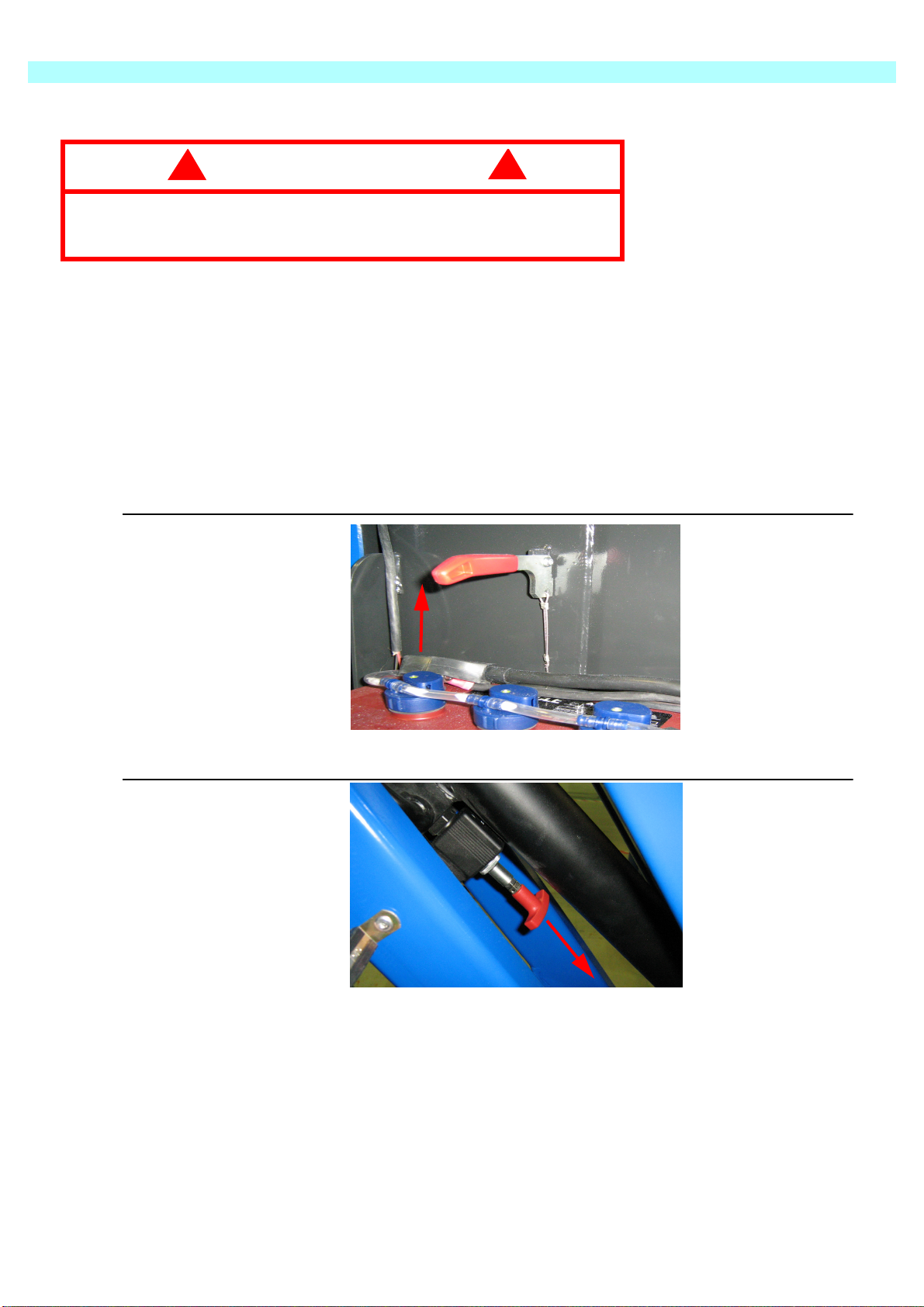
Should the machine become inoperable when elevated request a person on the
ground to lower the platform using the emergency lowering valves. Lower the mast
structure before lowering the jib/platform structure.
Locate the red lever behind the mast cover inspection door on the left hand side of the
machine. By pushing the lever up, the mast will descend fully under gravity. Releasing
the spring-loaded lever will cease this operation immediately if required.
Lower the masts fully before lowering the jib structure.
L
OWERING (BY HAND
)
Figure 8: Emergency Lowering - Mast Valve
Figure 9: Emergency Lowering - Jib Valve
The Jib may be manually lowered by operating the manual release valve located
between the Jib Structure (Figure 9).
M
ANUAL
1.Lower the masts and jib fully before manually slewing the assembly. Press the
Emergency Stop Button to prevent inadvertent powered motion.
2.Locate the opening behind the front right drive wheel. Apply a 7/8 inch socket wrench
with extension bar to the shaft and turn to rotate the elevating assembly. (Turning the
wheel fully to one side will facilitate this operation).
R
OTATION
Page 12
Page 19
5. T
80 cm above ground and in the plane of the energy chain which is located on the back
cover to the mast. Undo the 4 bolts connecting the ballast to the mast and use a forklift
Figure 10: Lifting by Forklift
WARNING
!
!
DANGER
!
!
RANSPORTATION
5
T
RANSPORTATION
M
ACHINE
Before transporting or lifting the MB20N/26 machine be aware of its weight. It is very
important to realise that the centre of gravity of the stowed machine is approximately
of the mast.
MB20N CE Version= 2550 kg
MB20N US Version= 3000 kg (6615 lbs)
MB26 CE Version = 2650 kg
MB26 US Version = 3150 kg (6945 lbs)
In cases of particular difficulties with lifting or shipping it is possible to remove the
single block ballast from the machine. Remove the 13 screws connecting the ballast
to remove the ballast block. The ballast block weighs 850 kg on the CE version and
1300kg on the US (ANSI) version.
W
EIGHTS
This work must not be carried out without the prior written permission
of UpRight Powered Access.
L
IFTING BY FORK
Forklifting is for transport only. See machine weights and ensure
that the forklift is of adequate capacity.
Adjust the forks so that
the minimum clearance
between them is 800mm
as shown above.
Approach the machine
from either side but place
the fork as close as
possible to the front wheel
as shown.
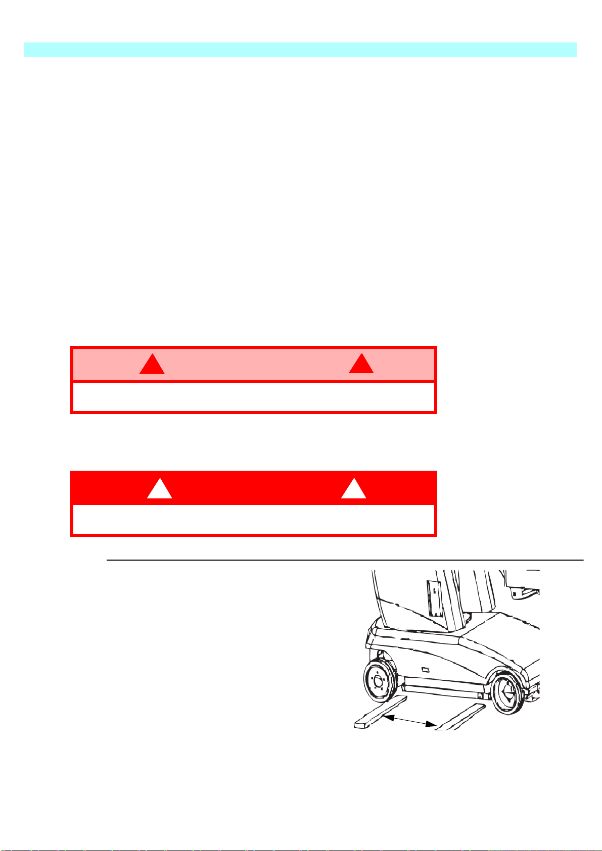
-L
IFT
Front
800mm
Page 13
Page 20
5
CAUTION
!
!
T
RANSPORTATION
1.Never approach the MB20 from the front or rear while fork lifting.
2.Use maximum forklift tilt as soon as possible when raising the MB20/26.
3.If travelling over sloped or uneven ground it is strongly recommended to temporarily tie
the MB20 jib mount structure to the forklift mast as a safety precaution.
4.The MB20/26 may be lifted by forklift subject to the following strict procedure.
5.Ensure that the mast and jib are fully stowed and that the pothole bars are fully
retracted (raised).
L
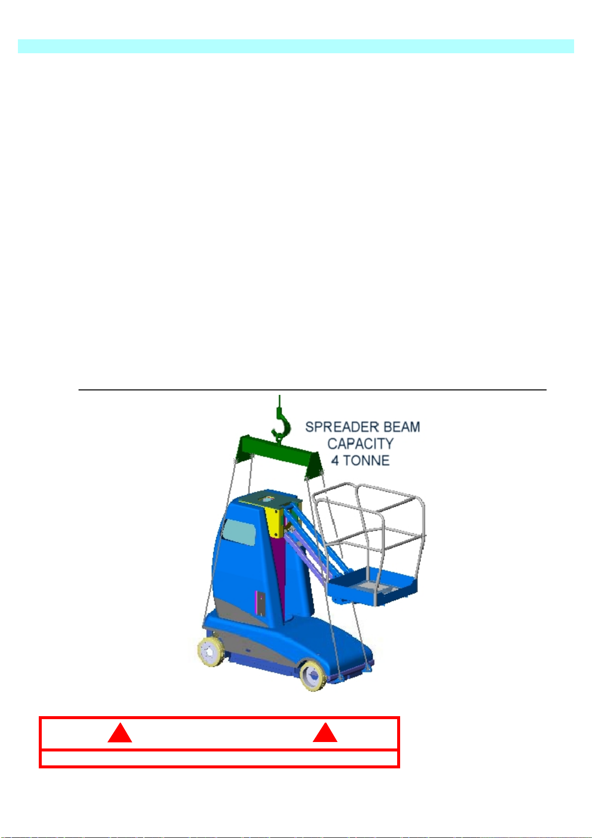
IFTING
The MB20/26 may be lifted by an overhead hoist/crane subject to the following strict
procedure.
Raise the jib to clear the lifting straps as shown.
Use 4 separate lifting straps connected to a spreader beam. DO NOT use a lesser
number of threaded straps as these could slip and lead to instability. The
recommended minimum capacity of EACH of the 4 straps is 2 tonne and the minimum
length of each strap is 2 metres. Damage to the covers and/or cage rails can occur if a
spreader beam is not deployed during a crane lift.
BY C
RANE
Apply the straps via 1 tonne shackles to each of the 4 lifting lugs on the chassis. See
Figure 9: below.
Figure 11: Lifting by Crane
DO NOT apply lifting straps to any other part of the machine.
Page 14
Page 21
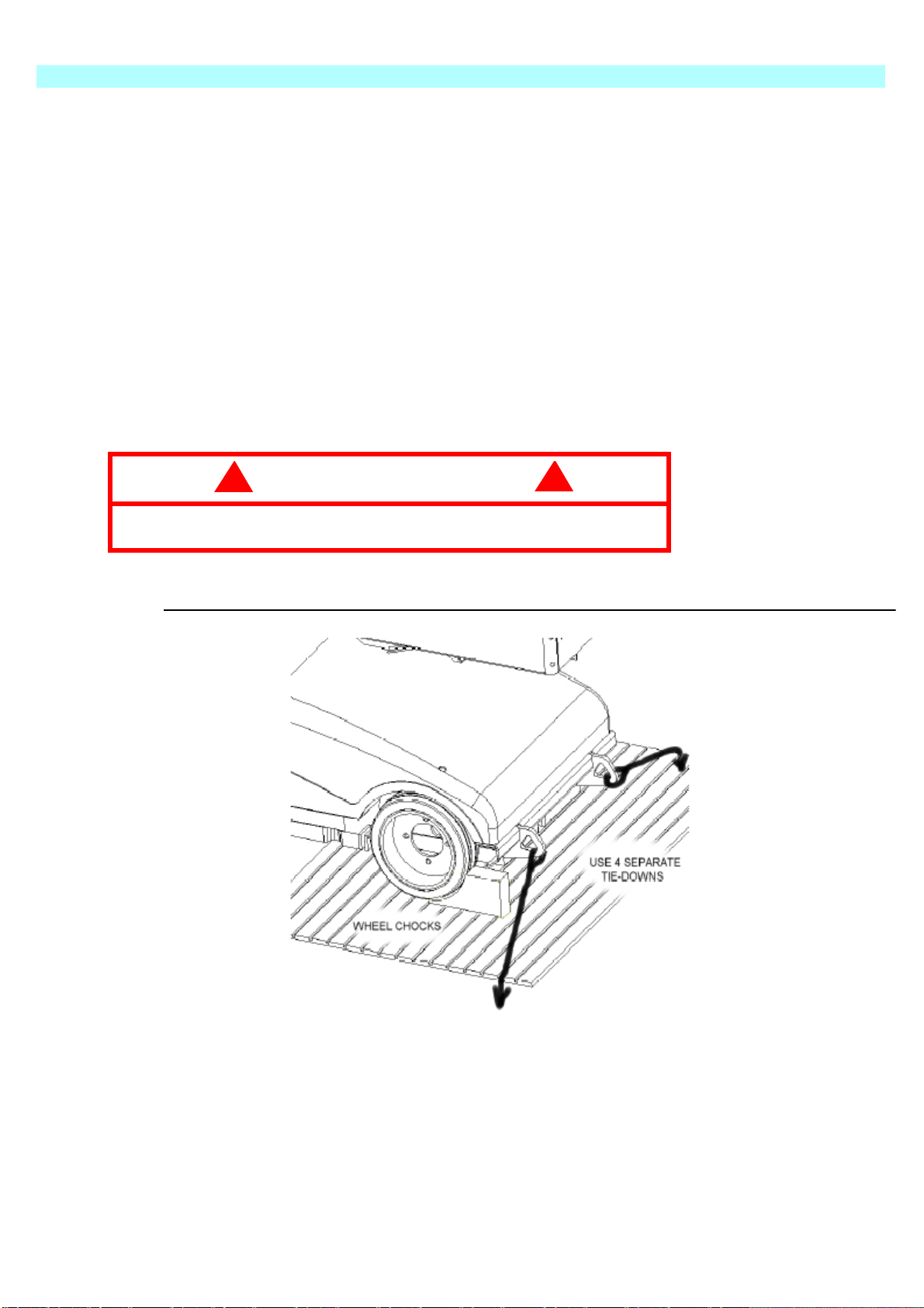
T
Because of its high gradeability, the machine can be driven under its own power on to
Figure 12: Securing the Platform
The fail-safe brakes are automatically applied when the machine comes to a stop or in
To tow the vehicle or to winch it on to a truck it is necessary to hydraulically bypass the
CAUTION
!
!
RANSPORT BY TRUCK
The MB20/26 can be carried on a suitably rated transportation vehicle or trailer.
a standard loading ramp (Up to 14 degrees).
It is recommended to reverse the machine up on to the truck thus forward travelling
down the ramp at the delivery point. Winch-assisted loading is allowable for larger
slopes, however, operate the trucks assist winch at minimum speed to avoid overpressurising the hydraulic system in the machine.
When the MB20/26 is on the truck or trailer it should then be made secure by:-
1.Chocking the wheels.
2.Securing with adequate chains or straps to the lifting lugs on the chassis.
DO NOT loop straps through the cage, ladder or jib as this could
cause permanent structural damage during transportation.
5
T
RANSPORTATION
T
OWING
the event of total power loss due to low battery or malfunction of the hydraulic drive
system.
control valves and release these brakes.
& W
INCHING
V
ALVES
Page 15
Page 22
5
WARNING
!
!
T
RANSPORTATION
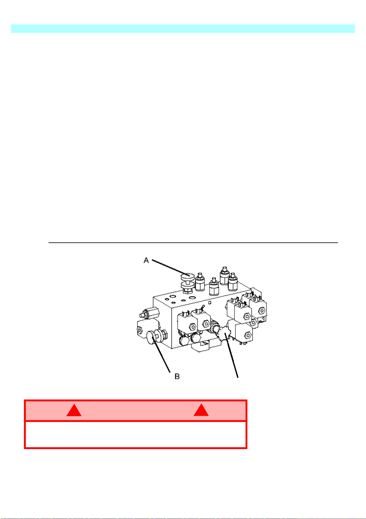
Proceed as follows:Refer to the valve block drawing Figure 13.
1.Fully lower the jib boom and the mast sections. Rotate the mast into the stowed
position.
2.Turn the Upper Control Box to the OFF position and remove the key.
3.Remove the rear GRP cover from the chassis and locate the hydraulic control valve
block.
4.The hand valve marked ‘A’ should be turned fully clockwise to close. The hand valve
marked ‘B’ should be turned fully anti-clockwise to open.
5.Operate the red handpump a number of times to develop sufficient pressure to
‘separate’ the internal brake disks. These brakes are integral with the hydraulic drive
motors.
NOTE: The machine can now be safely towed or winched.
6.On completion of towing/winching, reverse the position of the rotary hand valves ‘A’
and ‘B’. The handpump becomes inoperative when the valves are returned to their
normal position.
Figure 13: Valve Block-Towing Valves
Handpump
RISK OF SERIOUS INJURY. Releasing the brakes will cause the
machine to move uncontrollably on a slope. Damaging momentum
can be developed due to the large mass of a slow moving machine
Page 16
Page 23

6
Fill the hydraulic tank to operating level with the platform fully lowered. Fluid should be
Battery Disconnect
A
FTER USE
& S
TORAGE
6. A
FTER
U
SE
& S
A
1.Ensure that the platform (masts and jib) are fully lowered.
2.Park the machine on firm and level ground, never on a grass surface.
3.Turn the key switch to the OFF position and remove.
4.Put the batteries on charge.
H
1.Climb into the basket (with the machine powered up)
2.Push the platform emergency stop button.
3.Hold down the following buttons, Horn and Lift.
4.While holding the buttons twist the emergency stop button to return power to the
5.“hr.” will now be displayed on the read-out, Pressing the right turn button will scroll
TORAGE
FTER
OUR
To access the hour meter function perform the following steps.
machine.
through the accumulated hours two digits at a time. For example, if pressing the right
turn button once displays “20”, pressing it a 2nd time displays “58”, and pressing it a
3rd time displays “hr.”, the elapsed time of operation is 2058 hours.
U
SE EACH
M
ETER
D
AY
L
ONG
1.Clean and touch up damaged paint surfaces.
2.
3.Coat exposed portions of cylinder rods with a preservative such as multipurpose
4.Coat all exposed un-painted metal surfaces with a light oil or other preservative.
5.Cover the machine with tarpaulin if possible. If this is not available it is advisable to
-T
ERM
P
RESERVATION
visible on the tank dip stick.
grease and wrap with barrier material.
cover the mast and jib mount area as a minimum. This will prevent moisture from
entering the mast, battery and chassis areas.
S
TORAGE
Figure 14:
Battery disconnect
is located behind the
controller
Page 17
Page 24
6
WARNING
!
!
A
FTER USE
RISK OF SERIOUS INJURY. Take particular care when handling
batteries. Acid spills can cause severe burns or blindness.
DO NOT store batteries close to naked flames or close to steel
fabrication areas.
& S
TORAGE
B
ATTERIES
1.Disconnect the batteries at the quick connect plug and socket. This is located in the
chassis between the controller and the hydraulic tank.
2.Disconnect the battery leads and tape up the lead terminals to ensure insulation.
Better battery life and efficiency is achieved if the batteries are used consistently. It is
therefore recommended that the batteries are used elsewhere if the machine is to be
unused for an extended period (2 weeks or more).
Page 18
Page 25
D
WARNING
!
!
DAILY PREVENTATIVE MAINTENANCE CHECKLIST
AILY
P
REVENTATIVE
M
AINTENANCE
Daily daily preventative maintenance will prevent abnormal wear and prolong the life
of all systems. The inspection & maintenance schedule should be performed at the
specified intervals.
Inspection and maintenance shall be performed by personnel who are trained and
familiar with mechanical and electrical procedures.
Before performing preventative maintenance, familiarize yourself with
the operation of the machine.
Always block the elevating assembly whenever it is necessary to
perform maintenance while the platform is elevated.
This Daily checklist has been designed for machine service and maintenance.
Please photocopy this page and use the checklist when inspecting the machine.
C
HECKLIST
M
AINTENANCE TABLE
C
OMPONENT
B
ATTERY
C
HASSIS
C
ONTROL CABLE
C
ONTROLLER
D
RIVE MOTORS
E
LEVATING ASSEMBLY
E
MERGENCY LOWERING
S
YSTEM
E
NTIRE UNIT
H
YDRAULIC FLUID
H
YDRAULIC PUMP
H
YDRAULIC SYSTEM
L
ABELS
P
LATFORM DECK AND
R
AILS
T
YRES AND WHEELS
Y = Yes/Acceptable
N = No/Not Acceptable
R = Repaired/Acceptable
Check electrolyte level.
Check battery cable condition.
Check hoses for pinch or rubbing points.
Check welds for cracks.
Check the exterior of the cable for pinching, binding or wear.
Check switch operation.
Check for operation and leaks.
Inspect for structural cracks.
Operate the emergency lowering valve & check for serviceability.
Check for and repair collision damage.
Check fluid level.
Check for hose fitting leaks.
Check for leaks.
Check for peeling, missing, or unreadable labels & replace.
Check welds for cracks.
Check for damage.
P
K
EY
I
NSPECTION OR SERVICE
REVENTATIVE MAINTENANCE
Date:_______________________________________
Owner:_____________________________________
Model No:___________________________________
Serial No:___________________________________
Serviced By:_________________________________
R
EPORT
Y N R
Table 1: Daily Maintenance Checklist
Page 19
Page 26

S
PECIFICATIONS
S
PECIFICATIONS
MB20
P
ARAMETER
Duty Cycle
Platform Size
Maximum Platform Capacity
Maximum No. of Persons
Heights:
Maximum Platform Height
Maximum Working Height
Platform Height at Maximum Outreach
Maximum Working Outreach
Stowed Dimensions:
Length
Width
Height
Chassis Ground Clearance
Wheelbase x Wheel Gauge
Rotation
Gross Vehicle Weight
Maximum Drive Speed - Stowed
Maximum Drive Speed - Elevated
Maximum Gradeability
Outside Turning Radius
N
MB20N EU V
45%over 8 hour cycle
780mm x 745mm
215kg.
6.00m
8.00m
5.04m
2.64M 8.66ft.
2.222m
0.815m
1.990m
90mm
1465mm x 708mm
360deg non-continuous
2570kg.
3.03 km/h
0.70km/h
1.85m
ERSION
2
25%
MB20N US V
35%over 8 hour cycle
31in. x 29in.
425lbs.
19.69ft.
26.25ft.
16.54ft.
7.97ft.
3.54in.
4.81ft. x 2.32ft.
360 deg non-continuous
6674lbs.
1.9mph.
0.43mph
6.10ft.
ERSION
2
32in.
6.50ft
25%
Electrical:
Power Source
System Voltage
Battery Charger
Control System
Hydraulic System:
System Relief Setting
Hydraulic Oil Type
Hydraulic Tank Capacity
Brakes
Wheel & Tyres 13.5in. x 4.0
Noise Pressure Level
4 x 6V @ 375Ah Battery
24 Volt DC
24V x 30A, 220V 50Hz AC
Single Joystick, Function
Selector, DC Motor Controller
220bar
ISO VG46
20 litres
Spring applied hydraulically
released
solid, Non-Marking
68dB (A) at Control Station 68dB (A) at Control Station
4 x 6V @ 375Ah Battery
24 Volt DC
24V x 30A, 110V 60Hz AC
Single Joystick, Function
Selector, DC Motor Controller
3190psi
ISO VG46
5.3 gallons (U.S.)
Spring applied hydraulically
released
13.5in. x 4.0
solid, Non-Marking
Page 20
Page 27

S
PECIFICATIONS
MB26
P
ARAMETER
MB26 EU V
ERSION
S
PECIFICATIONS
MB26 US V
ERSION
Duty Cycle
Platform Size
Maximum Platform Capacity
Maximum No. of Persons
Heights:
Maximum Platform Height
Maximum Working Height
Platform Height at Maximum Outreach
Maximum Working Outreach
Stowed Dimensions:
Length
Width
Height
Chassis Ground Clearance
Wheelbase x Wheel Gauge
Rotation
Gross Vehicle Weight
Maximum Drive Speed - Stowed
Maximum Drive Speed - Elevated
Maximum Gradeability
Outside Turning Radius
45%over 8 hour cycle
780mm x 745mm
215kg.
2
7.79m
9.79m
6.51m
3m 10ft.
2.825m
0.990m
1.990m
90mm
1465mm x 890mm
360deg non-continuous
2672kg.
3.03 km/h
0.70km/h
25%
2.10m
35%over 8 hour cycle
31in. x 29in.
425lbs.
2
26.00ft.
32.00ft.
21.36ft.
9.3ft.
39in.
6.54ft.
3.54in.
4.81ft. x 2.93ft.
360 deg non-continuous
7012lbs.
1.9mph.
0.43mph
25%
6.90ft.
Electrical:
Power Source
System Voltage
Battery Charger
Control System
Hydraulic System:
System Relief Setting
Hydraulic Oil Type
Hydraulic Tank Capacity
Brakes
Wheel & Tyres 13.5in x 4.0
Noise Pressure Level
4 x 6V @ 375Ah Battery
24 Volt DC
24V x 30A, 220V 50Hz AC
Single Joystick, Function
Selector, DC Motor Controller
220bar
ISO VG46
18 litres
Spring applied hydraulically
released
solid, Non-Marking
68dB (A) at Control Station 68dB (A) at Control Station
4 x 6V @ 375Ah Battery
24 Volt DC
24V x 30A, 110V 60Hz AC
Single Joystick, Function
Selector, DC Motor Controller
3190psi
ISO VG46
4.7 gallons (U.S.)
Spring applied hydraulically
released
13.5in x 4.0
solid, Non-Marking
Page 21
Page 28

Notizen:
Page 29
MB 20N/26
Seriennummern MB20N 132 - aktuelles Modell
MB26 246 - aktuelles Modell
DEUTSCH
Wenn Sie bei UpRight Powered Access Serviceoder Teileinformationen anfordern, halten Sie
die MODELL- und SERIENNUMMERN vom
Typenschild der Maschine bereit. Falls das
Typenschild fehlen sollte, ist die
SERIENNUMMER auch auf dem Chassis über
dem vorderen Achsschenkel eingeprägt.
Typenschild
Das Typenschild der Arbeitsplattform
befindet sich außen an der VORDERSEITE
des Chassis
Wenn Sie bei UpRight Powered Access Service- oder Teileinformationen anfordern,
halten Sie die MODELL- und SERIENNUMMERN vom Typenschild der Maschine bereit.
Die Arbeitsplattform MB20N/26 erfüllt bzw. übertrifft die Anforderungen folgender Normen:
prEn280:2001 und ANSI A92.5 (1999)
Page 30

Notizen:
Page 31

S
! !
WARNUNG
Alle Bediener müssen die Sicherheitsregeln und Betriebsanleitungen gründlich durchlesen,
verstehen und befolgen, bevor sie an irgendeiner UpRight-Hocharbeitsbühne Wartungsarbeiten
ausführen oder die Arbeitsbühne in Betrieb nehmen.
Sicherheitsregeln
Elektroschockgefahr Kippgefahr Kollisionsgefahr
DIESE MASCHINE IST NICHT
ISOLIERT!
EINSATZ DER HOCHARBEITSBÜHNE: Diese Hocharbeitsbühne dient dazu, Personen und Werkzeuge sowie die für die jeweilige Arbeit
erforderlichen Materialien zu transportieren. Sie wurde speziell für Reparatur- und Montagearbeiten sowie für Einsatzbereiche k
die sich oberhalb der Mitarbeiter befinden, sodass die Mitarbeiter nach oben gerichtet arbeiten müssen (z. B. Decken, Kräne,
Dachstrukturen, Gebäude etc.). Jede andere Verwendung der Hocharbeitsbühne ist strikt verboten!
DIESE HOCHARBEITSBÜHNE IST NICHT ISOLIERT! Aus diesem Grund muss zwingend ein Sicherheitsabstand zu allen leitfähigen
Teilen der elektrischen Ausrüstung eingehalten werden!
Die angegebene zulässige Höchstlast darf nicht überschritten werden!Nähere Informationen hierzu finden Sie im Abschnitt
“Beschränkungen” auf Seite 4.
Es ist strikt verboten, die Hocharbeitsbühne als Hubwerkzeug oder Kran einzusetzen (d. h. um Lasten von unten nach oben oder von
oben nach unten zu befördern).
Die für diese Maschine zulässige manuelle Kraft NIEMALS überschreiten.Nähere Informationen hierzu finden Sie im Abschnitt
“Beschränkungen” auf Seite 4.
Lasten immer gleichmäßig auf der Plattform VERTEILEN.
Vor Inbetriebnahme der Maschine IMMER ZUERST die Aufstellfläche im Arbeitsbereich auf Gefahren wie Bodenlöcher, ausgelaufene
Flüssigkeiten, Bodenerhebungen, Kanten oder Schutt untersuchen und diese umgehen bzw. beseitigen.
Maschine nur auf Oberflächen IN BETRIEB NEHMEN, die die zulässigen Radlasten aufnehmen können.
Maschine NIEMALS in Betrieb nehmen, wenn die tatsächliche Windgeschwindigkeit höher ist als die Windgeschwindigkeit, für die die
Maschine ausgelegt ist. Nähere Informationen hierzu finden Sie im Abschnitt “Beaufort-Skala” auf Seite 4.
IM NOTFALL NOT-AUS-Schalter drücken, um alle strombetriebenen Funktionen zu deaktivieren.
WENN EIN ALARM ERTÖNT, während die Plattform ausgefahren wird, Plattform ANHALTEN und vorsichtig einfahren (absenken).
Maschine auf feste, ebene Oberfläche fahren.
Auf das Schutzgeländer der Plattform zu klettern, auf Gebäuden, Stahl- oder vorgefertigten Betonstrukturen zu stehen oder von der
Plattform aus darauf zu klettern etc. ist verboten!
Das Schwingtor oder andere Komponenten des Schutzgeländers zu demontieren ist verboten! Vergewissern Sie sich immer, dass das
Schwingtor geschlossen und sicher verriegelt ist!
Es ist verboten, das Schwingtor geöffnet zu halten (z. B. mit Befestigungsgurten), wenn die Arbeitsplattform ausgefahren wird!
Die Höhe oder Reichweite der Plattform durch Anbringen von Leitern, Gerüsten oder ähnlichen Vorrichtungen zu vergrößern ist
verboten!
IMMER ZUERST die Hubvorrichtung blockieren, bevor bei ausgefahrener Plattform Wartungs- oder Instandhaltungsarbeiten an der
Maschine durchgeführt werden.
Maschine vor jedem Gebrauch sorgfältig auf Risse an Schweißstellen, lose oder fehlende Beschläge, Leckagen in der
Hydraulikvorrichtung, gelöste Kabelverbindungen und beschädigte Kabel oder Schläuche UNTERSUCHEN.
Vor Gebrauch SICHERSTELLEN, dass alle Bezeichnungsschilder ordnungsgemäß angebracht und vollständig lesbar sind.
NIEMALS eine Maschine benutzen, die beschädigt ist, nicht ordnungsgemäß funktioniert oder deren Bezeichnungsschilder
Beschädigungen aufweisen oder sogar ganz fehlen.
Sicherheitseinrichtungen zu umgehen ist verboten und stellt eine Gefahr für alle Personen dar, die sich auf der Hocharbeitsbühne und in
deren Arbeitsbereich befinden.
Batterien NIEMALS in der Nähe von Funkenquellen oder offenen Flammen aufladen. Beim Aufladen von Batterien wird explosives
Wasserstoffgas freigesetzt.
Änderungen an der Hocharbeitsbühne sind verboten bzw. nur mit ausdrücklicher Genehmigung von
NACH GEBRAUCH ist die Hocharbeitsbühne gegen unbefugten Gebrauch durch Dritte zu sichern. Hierzu müssen beide
Schlüsselschalter auf “Aus” gestellt und die Schlüssel abgezogen werden.
NIEMALS die Plattform ausfahren
oder die Maschine mit
ausgefahrener Plattform
fortbewegen, wenn sich die
Maschine nicht auf einer festen,
ebenen Fläche befindet.
Plattform NIEMALS in Position
bringen, ohne vorher
sicherzustellen, dass der Bereich
über der Plattform frei von
Hindernissen und anderen
Gefahren ist.
UpRight zulässig.
turzgefahr
NIEMALS auf das obere oder
mittlere Gestänge des
Plattformgeländers klettern
und auch nicht darauf stehen
oder sitzen.
onzipiert,
Page 32

I
NHALT
1. E
INFÜHRUNG
Abbildung 1. Informationen zum Aufbewahren
der Betriebsanleitung 1
S
2. A
LLGEMEINE
PEZIELLE INFORMATIONEN
B
ESONDERE EINSCHRÄNKUNGEN
M
ANUELLE
P
LATTFORMKAPAZITÄT
B
EAUFORT-SKALA
B
ESCHREIBUNG
K
RAFT
Abbildung 2. Arbeitsplattform 3
3. S
ICHERHEITSPRÜFUNG
Abbildung 3. Fülltaste und Ventil für Batterie 4
Abbildung 4. Untere Bedienkonsole 4
Abbildung 5. Joystick und Neigungssensor 6
4. B
ETÄTIGUNG DER BEDIENELEMENTE
O
BERE BEDIENKONSOLE
DER PLATTFORM
Abbildung 6. Obere Bedienkonsole 7
S
TEUERFUNKTIONEN
Tabelle 1. Bedienelemente und Anzeigen der Plattform
U
NTERE BEDIENKONSOLE
Tabelle 2. Bedienelemente und Anzeigen am Chassis 9
Abbildung 7. Untere Bedienkonsole 9
T
YPISCHER BETRIEB
B
EDIENELEMENTE
A
NHEBEN UND ABSENKEN DER ARBEITSPLATTFORM
F
AHREN MIT ABGESENKTER ARBEITSPLATTFORM
F
AHREN MIT ANGEHOBENER
N
OTFÄLLE
A
BSENKUNG IM NOTFALL (VON HAND
UND ANZEIGEN
A
RBEITSPLATTFORM
Abbildung 8. Absenkung im Notfall (Mastventil) 12
Abbildung 9. Absenkung im Notfall (Auslegerventil) 12
5. T
RANSPORT
M
ASCHINENGEWICHTE
Abbildung 10. Anheben mit einem Gabelstapler 13
A
NHEBEN MIT EINEM KRAN
Abbildung 11. Anheben mit einem Kran 14
T
RANSPORT MIT EINEM LASTWAGEN
Abbildung 12. Sichern der Plattform 15
S
CHLEPP- UND
W
INDENVENTILE
Abbildung 13. Schleppventile am Ventilblock 16
6. A
RBEITEN NACH DEM BETRIEB UND VOR DER LAGERUNG
N
ACH DEM TÄGLICHEN GEBRAUCH
B
ETRIEBSSTUNDENZÄHLER
L
ANGZEITLAGERUNG
K
ONSERVIERUNG
Abbildung 14. Abklemmen der Batterie 17
B
ATTERIEN
C
HECKLISTE FÜR TÄGLICHE WARTUNGSARBEITEN
Tabelle 1. Checkliste für tägliche Wartungsarbeiten 19
7. T
ECHNISCHE DATEN
MB20N 20
MB26
21
11
)
12
S
Contents
EITE
1
1
1
1
2
2
2
3
7
7
8
8
9
9
10
10
11
11
13
13
14
15
15
17
17
17
17
17
18
19
Page 33

1 Einführung
1. E
INFÜHRUNG
Diese Betriebsanleitung enthält Anweisungen und Bilder zur sicheren Verwendung
und Bedienung der Arbeitsplattformen MB20N und MB26 von Upright Powered
Access Ltd.
Abbildung 1: Informationen zum Aufbewahren der Betriebsanleitung
Die Betriebsanleitung MUSS
IMMER in dem dafür
vorgesehenen Fach im
Maschinenkäfig aufbewahrt
werden.
S
PEZIELLE
In diesem Handbuch sollen die folgenden speziellen Rahmen die Aufmerksamkeit des
Benutzers auf sich ziehen:
GEFAHR
! !
Weist auf eine unmittelbare, gefährliche Situation hin, die, falls
sie nicht vermieden wird, zu schweren Verletzungen oder zum
Tod führen kann.
I
NFORMATIONEN
!
WARNUNG
Weist auf eine mögliche, gefährliche Situation hin, die, falls sie
nicht vermieden wird, zu schweren Verletzungen oder zum Tod
führen könnte.
!
VORSICHT
Weist auf eine mögliche, gefährliche Situation hin, die, falls sie
nicht vermieden wird, zu leichten oder mittleren Verletzungen
führen kann.
B
ESONDERE
Zweck dieser Maschine ist es, schnellen und sicheren Zugriff auf Bereiche zu
ermöglichen, die nur schwer zugänglich sind.
Informationen zu den Zugriffsbeschränkungen der Maschine finden Sie im Abschnitt
"Technische Daten".
Bei angehobener Plattform kann die Maschine nur mit sehr geringer Geschwindigkeit
bewegt werden.
M
ANUELLE
Unter manueller Kraft versteht man die Kraft, die von den Insassen auf Objekte wie
Wände oder andere Strukturen außerhalb der Arbeitsplattform angewandt wird. Die
maximale manuelle Kraft ist auf 200 N pro Insasse begrenzt und darf insgesamt
maximal 400 N betragen.
E
INSCHRÄNKUNGEN
K
RAFT
!
!
GEFAHR
! !
Überschreiten Sie NICHT die maximale manuelle Kraft.
Überschreiten Sie NIEMALS die Plattformkapazität.
Seite 1
Page 34

2
A
LLGEMEINE BESCHREIBUNG
P
LATTFORMKAPAZITÄT
Die Plattform ist dafür ausgelegt, sich mit einer sicheren Arbeitslast
Arbeitswerkzeugen bis zu einem maximalen Gewicht von
B
EAUFORT
Setzen Sie die Maschine niemals bei Windgeschwindigkeiten von über 12,5 m ein
[Beaufort-Skala 6].
W
B
EAUFORT
INSTUFUNG
E
-
M/S KM/H FT./S M.P.H
3 3,4~5,4 12,25~19,4 11,5~17,75 7,5~12,0
4 5,4~8,0 19,4~28,8 17,75~26,25 12,0~18
5 8,0~10,8 28,8~38,9 26,25~35,5 18~24,25
6 10,8~13,9 38,9~50,0 35,5~45,5 24,5~31
7 13,9~17,2 50,0~61,9 45,5~56,5 31,0~38,5
INDGESCHWINDIGKEIT
-S
KALA
(SAL)
einschließlich
215 kg
B
.
Papier und dünne Äste bewegen sich.
Fahnen bewegen sich im Wind.
Staub und Papier werden aufgewirbelt, kleine Äste
wiegen sich hin und her.
Laubsträucher beginnen, sich hin und her zu bewegen.
In Teichen oder Sümpfen werden Wellenkämme sichtbar.
Äste in Bäumen bewegen sich.
Stromleitungen pfeifen. Ein Regenschirm lässt sich nur
noch schwer öffnen.
Ganze Bäume wiegen sich hin und her.
Es ist schwierig, gegen den Wind zu laufen.
ODENBEDINGUNGEN
zu bewegen.
2. A
LLGEMEINE
Verwenden Sie die Einheit NICHT auf weichem Untergrund oder an
Steigungen mit über 2 Grad Gefälle.
Die Arbeitsplattform ist NICHT für die Verwendung auf unebenem
oder rauem Gelände vorgesehen.
Bedienen Sie diese Maschine NUR auf FESTEM und EBENEM
Untergrund.
Wenn Sie mit dem Hebemechanismus Gegenstände oder Personen
anheben, MÜSSEN sich diese im Käfig befinden. Die angegebene
Gewichtsbeschränkung darf nicht überschritten werden.
B
ESCHREIBUNG
Bei den MB20/26 handelt es sich um schnell bewegliche Arbeitsplattformen mit
eigenem Antrieb, mit denen zwei Bediener mit Handwerkzeugen auf eine
Plattformhöhe von 6,00 m bzw. 7,76 m angehoben werden können. Die maximale
Zugriffshöhe liegt bei etwa 2,00 m über diesen Angaben.
Die Einheit ermöglicht es, Hindernisse zu überwinden, muss jedoch beim Einsatz stets
auf festem und ebenen Untergrund stehen.
GEFAHR
! !
GEFAHR
! !
Seite 2
GEFAHR
! !
Steigen Sie NICHT von einer anderen Konstruktion, einem Gerüst
oder einer anderen Plattform auf die Plattform.
Page 35

Hubeinheit
3
S
ICHERHEITSPRÜFUNG
Abbildung 2: Arbeitsplattform
Steuerung
der Plattform
Sicherungsstange
Plattform
Bedienelemente
für das Chassis
Chassis
3. S
!
WARNUNG
Verwenden Sie die Arbeitsplattform NICHT ohne installierte
Sicherungsstange. Auch das Sicherheitsgeschirr muss stets
angelegt sein.
ICHERHEITSPRÜFUNG
Diese Sicherheitsprüfung kann vom Eigentümer unmittelbar vor dem Transport dieser
Maschine durchgeführt werden.
Diese Sicherheitsprüfung kann vom Benutzer auch täglich vor Benutzung der
Maschine durchgeführt werden.
Für die Prüfung müssen die folgenden 14 Schritte in der angegebenen Reihenfolge
ausgeführt werden.
1. Entfernen Sie die hinteren Chassisabdeckungen, indem Sie die beiden oberen
Verriegelungszapfen und die beiden Hebe-Dreh-Verschlüsse an den Seiten lösen. Die
Abdeckung lässt sich durch Schieben nach hinten und oben entfernen. Verwenden Sie
hierfür den zentral angebrachten Griff.
2. Vergewissern Sie sich, dass Mast und Ausleger ganz eingefahren sind. Nehmen Sie
die Abdeckung des Öleinfüllstutzens ab, und überprüfen Sie den Hydraulikölstand. Auf
dem Ölmessstab muss Öl sichtbar sein. Füllen Sie gegebenenfalls Hydrauliköl mit
dem Viskositätsgrad ISO 46 nach.
!
3. Überprüfen Sie den Chassisbereich auf Öllecks, lose Teile, durchgescheuerte Kabel
und Schläuche sowie strukturelle Schäden. Achten Sie außerdem darauf, dass alle
Kabelanschlüsse zu den Magnetventilen intakt sind.
Seite 3
Page 36

3
S
ICHERHEITSPRÜFUNG
Absperrventil
In GESCHLOSSENER
Position
4. Öffnen Sie die Inspektionsluken auf beiden Seiten der oberen Mastabdeckung.
Vergewissern Sie sich, dass das Netzanschlusskabel nicht am Batterieladegerät
angeschlossen ist. Überprüfen Sie den Elektrolytstand in allen Batteriezellen. Füllen
Sie gegebenenfalls destilliertes Wasser nach.
5. Verwenden Sie das automatische Batterieauffüllsystem, um den erforderlichen
Elektrolytstand wiederherzustellen. Öffnen Sie hierfür das Absperrventil, und drücken
Sie etwa 10 Sekunden lang auf die grüne Fülltaste. Schließen Sie anschließend das
Absperrventil.
Die Batterien müssen auf Risse, austretende Säure und korrodierte Klemmen
überprüft werden. Beheben Sie eventuell festgestellte Schäden sofort.
Abbildung 3: Fülltaste und Ventil für Batterie
Fülltaste für Batterie
!
VORSICHT
!
Füllen Sie die Batteriezellen bei Fahrzeugen, die mit einem
automatischen Batteriefüllsystem mit Absperrventil ausgestattet
sind, mit Hilfe der Elektrolytfülltaste mit destilliertem Wasser auf.
Achten Sie dabei darauf, dass das Absperrventil während der
Befüllung geöffnet ist, und schließen Sie es nach dem Auffüllen
wieder.
Das Ventil darf nur zu diesem Zweck geöffnet werden.
1. Aktivierungsschalter
2. Analoger Wippschalter
3. Mastschalter
4. Auslegerschalter
Abbildung 4: Untere Bedienkonsole
1
2
3
4
Seite 4
5. Drehschalter
6. Not-Aus-Schalter
5
6
Page 37

3
S
ICHERHEITSPRÜFUNG
6. Überprüfen Sie vor dem Aktivieren der Funktionen, dass die oberen und unteren
Not-Aus-Schalter an allen Bedienstationen zurückgezogen sind. Drehen Sie diese
gegebenenfalls im Uhrzeigersinn. Aktivieren Sie die folgenden Funktionen von der
unteren Bedienstation aus.
HINWEIS: Betreten Sie in dieser Phase NICHT die Plattform.
7. Überprüfen Sie die Auslegerfunktion, indem Sie den Ausleger ganz nach oben fahren.
Vergewissern Sie sich, dass alle Schläuche und Kabel richtig verlegt sind. Überprüfen
Sie die Notabsenkfunktion des Auslegers. Vergewissern Sie sich, dass sich der
Ausleger bei gelöstem Notabsenkhebel/bei gelöstem Notabsenkschalter nicht weiter
nach unten bewegt. Bringen Sie den Ausleger über die normale untere Bedienstation
wieder in seine Ausgangsposition.
8. Überprüfen Sie die Mastketten, indem Sie die Masten etwa 30 cm über ihre
Ausgangsposition bringen. Vergewissern Sie sich, dass die Energiekette richtig verlegt
ist. Fahren Sie die Masten bis zur maximalen Höhe aus, und prüfen Sie, ob alle
Hubketten richtig ausgerichtet sind. Gehen Sie dazu wie folgt vor: Jedes Kettenpaar
muss belastet sein. Verwenden Sie eine Handfederwaage oder ein Tensiometer, und
wenden Sie eine nominale Last (etwa 10 kg) auf beide Ketten des Kettenpaars an.
Wenden Sie die Last etwa in der Mitte der Kette an. Notieren Sie die ungefähre
Durchbiegung, d. h. den Versatzabstand vom Mast. Wiederholen Sie die Messung an
der benachbarten Kette an derselben Stelle. Gleich belastete Ketten weisen dieselbe
Durchbiegung auf. Stellen Sie die losere Kette so ein, dass die Durchbiegungen in
etwa gleich sind. Ziehen Sie die Sicherungsmuttern mit 70 Nm fest.
HINWEIS: Tragen Sie mit einem kleinen Pinsel eine dünne Fettschicht auf die Hubketten
auf.
!
VORSICHT
Eine Überspannung einer der Hubketten führt zu einer unnötigen
Anhebung des Masts, wodurch die Maschine im eingefahrenen
Zustand eine größere Höhe aufweist.
Die Mastriemen sollen zum einen sicherstellen, dass sich die Masten in der richtigen
Reihenfolge absenken. Viel wichtiger ist jedoch, dass sie dafür sorgen, dass sich die
Masten nicht weiter absenken können, wenn Ausleger oder Plattform auf ein externes
Hindernis treffen. Heben Sie die Masten etwa 30 cm an. Überprüfen Sie die äußeren
Mastklemmschrauben auf festen Sitz. Ziehen Sie am kürzeren Teil der Riemen, und
überprüfen Sie, ob diese sicher sitzen. Anweisungen zur regelmäßigen, genaueren
Überprüfung dieser Riemen finden Sie im Wartungshandbuch.
Überprüfen Sie die Notabsenkfunktion des Masts. Der Hebel befindet sich am oberen
Mastende. Öffnen Sie die linke Batterieprüfluke, und suchen Sie das Etikett mit der
Aufschrift "Emergency Lowering" (Notabsenkung). Überprüfen Sie die Abriebpolster
auf Beschädigungen oder starke Abnutzung. Ersetzen Sie diese bei Bedarf.
9. Heben Sie den Ausleger vollständig an. Drehen Sie die gesamte Masteinheit mit Hilfe
der unteren Bedienstation um etwa 90 Grad. Überprüfen Sie, ob die Schläuche und
Kabel richtig verlegt sind und ob die Energiekette in der Schiene der Chassisbasis
problemlos läuft. Drehen Sie den Mast weiter um 180 Grad in beide Richtungen.
Vergewissern Sie sich, dass die Drehanschläge intakt sind.
!
10. STANDARDBEDIENELEMENTE FÜR DIE PLATTFORM Wiederholen Sie die Mast-,
Ausleger- und Drehfunktionen von der oberen Bedienstation der Plattform. Überprüfen
Sie, ob nach dem Drücken des Not-Aus-Schalters der Joystick funktionslos wird.
Seite 5
Page 38

3
S
ICHERHEITSPRÜFUNG
11. NOTFALLÜBERSTEUERUNG Bitten Sie einen Kollegen, während Sie auf der
Plattform stehen, den Neigungsalarmsensor zu kippen. Dieser Sensor befindet sich in
der Chassisbasis. Der Alarm ertönt, und alle normalen Funktionen werden
unterbrochen.
Abbildung 5: Joystick und Neigungssensor
Neigungssensor
Joystick
mit Totmanngriff
12. MASCHINENBEWEGUNG – OHNE ANGEHOBENE PLATTFORM
Die Bewegungsfunktionen können nur von der oberen Bedienstation der Plattform aus
aktiviert werden. Wie bei solchen Bedienelementen üblich, muss zunächst der
Totmannschalter gedrückt werden, bevor sich die Funktionen aktivieren lassen.
Wählen Sie in der oberen Bedienkonsole die Option "Drive" (Antrieb) aus. Durch
Drücken des Joysticks nach vorne oder hinten bewegt sich die Maschine in Vorwärtsoder Rückwärtsrichtung.
Die Kippschutzbalken werden sofort eingefahren. Die maximale Geschwindigkeit kann
erst erreicht werden, wenn die Balken ganz angehoben sind. Dies dauert etwa 3
Sekunden. Überprüfen Sie, dass der Bewegungsalarm ERTÖNT, während die
Maschine bewegt wird. Stellen Sie sicher, dass die mit dem Daumen betätigten
Schalter oben am Joystick die Vorderräder lenken.
13. MASCHINENBEWEGUNG – BEI ANGEHOBENER PLATTFORM Mit angehobenen
Masten kann die Maschine mit wesentlich geringerer Geschwindigkeit gefahren und
gelenkt werden. Beachten Sie auch, dass bei angehobenen Masten die
Kippschutzbalken vollständig ausgefahren sein müssen – selbst dann, wenn die
Maschine mit langsamer Geschwindigkeit bewegt wird.
!
WARNUNG
Diese Geschwindigkeitsverringerung bei angehobenen Masten
und das Ausfahren der Kippschutzbalken ist ein wesentlicher
Bestandteil der Sicherheitsfunktionen dieser Maschine.
Die Maschine darf nicht betätigt werden, wenn diese Funktionen
nicht einwandfrei ausgeführt werden können.
!
Seite 6
14. LETZTE VORBEREITUNGEN Fahren Sie die Masten und den Ausleger ein. Bringen
Sie alle Maschinenabdeckungen wieder an, und befestigen Sie diese.
HINWEIS: Die Maschine kann jetzt betrieben oder transportiert werden.
Page 39

4
B
ETÄTIGUNG DER BEDIENELEMENTE
DER PLATTFORM
4. B
ETÄTIGUNG
DER
B
EDIENELEMENTE
Das primäre (obere) Bedienfeld ist an der Vorderseite der Plattform befestigt. Es ist mit
einem Multifunktions-Joystick ausgestattet, der eine proportionale Betätigung aller
Maschinenfunktionen ermöglicht. Hierzu gehören das Anheben oder Absenken des
Masts, das Anheben oder Absenken des Auslegers, das Drehen der Masteinheit
sowie das Fahren und Lenken der Maschine.
Der Joystick ist mit einem Sicherheitsverriegelungsschalter oder "Totmannschalter"
ausgestattet. Dieser muss stets aktiviert werden, um eine Funktion auszuführen.
Diese Funktion ermöglicht die Bedienung mit einer Hand.
Das sekundäre (untere) Bedienfeld ist an der Mastabdeckung auf Armhöhe
angebracht. Es ist mit einem Aktivierungsschalter und Wahlschaltern ausgestattet, die
vorprogrammierte Geschwindigkeiten für alle Funktionen zur Verfügung stellen, mit
Ausnahme von Fahren und Lenken. Diese Bedienstation wird vor allem für den
Wartungsbetrieb verwendet. Hierzu zählt auch die Überprüfung vor der
Inbetriebnahme. Sie darf niemals zum Positionieren einer bemannten oder
unbemannten Plattform verwendet werden.
HINWEIS: Sie kann im Notfall zum Absenken der bemannten Plattform verwendet
werden.
DER
P
LATTFORM
!
WARNUNG
Bedienen Sie die Maschine NUR über die oberen Bedienelemente,
wenn die Sicherungsstange am Eingang der Plattform vollständig
abgesenkt und das Sicherheitsgeschirr angelegt ist.
O
BERE
1. Joystick (vorwärts/rückwärts)
2. Totmanngriff
3. Not-Aus-Schalter
4. Lenkschalter (L/R)
5. Wahlschalter Ausleger
6. Wahlschalter Mast
7. Wahlschalter Drehen
8. Antrieb (langsam)
B
EDIENKONSOLE
!
Abbildung 6: Obere Bedienkonsole
9. Antrieb (schnell)
10. Schlüsselschalter
11. Hupe 12. MultifunktionsDisplay
Seite 7
Page 40

4
B
ETÄTIGUNG DER BEDIENELEMENTE DER PLATTFORM
S
TEUERFUNKTIONEN
E
LEMENT
B
EZEICHNUNG
1Joystick
F
UNKTION
Die richtige Bewegungsrichtung entnehmen Sie bitte den
aufgeklebten Logikdiagrammen.
Bei Auswahl von "Drive" (Antrieb) bewegt sich die
Maschine beispielsweise in Vorwärtsrichtung, wenn der
Joystick nach vorne gedrückt wird.
2 Totmanngriff
Der "Totmannschalter" am Joystick muss festgehalten
werden, damit sich die Funktionen aktivieren lassen.
Drücken Sie diesen roten Schalter jederzeit, wenn Sie die
3 Not-Aus-Schalter
Stromversorgung unterbrechen möchten.
Drehen Sie ihn im Uhrzeigersinn, um ihn zurückzusetzen.
4 Lenkschalter Dreht die Räder nach links oder rechts.
5 Wahlschalter Ausleger Dient zur Vorauswahl der Auslegerfunktion.
6 Wahlschalter Mast Dient zur Vorauswahl der Mastfunktion.
7 Wahlschalter Drehen Dient zur Vorauswahl der Drehfunktion.
Dient zur Vorauswahl der Fahrfunktion mit angehobenem
8 Antrieb (Mast angehoben)
Mast und mit hohem Drehmoment (d. h. niedrige
Geschwindigkeit)
9 Antrieb (Mast abgesenkt)
10 Schlüsselschalter
11 Hupe
12 Multifunktions-Display
Tabelle 1: Bedienelemente und Anzeigen der Plattform
Seite 8
Dient zur Vorauswahl der Fahrfunktion mit abgesenktem
Mast (d. h. maximale Geschwindigkeit)
Aktiviert (ON) und deaktiviert (OFF) alle
Maschinenfunktionen.
Dient zum Warnen anderer Personen oder dazu, deren
Aufmerksamkeit zu wecken.
Zeigt die Batterielebensdauer in Prozent an. (99=Voll,
01=Leer)
Page 41

U
NTERE
E
LEMENT
B
EZEICHNUNG
1 Aktivierungsschalter
4
B
B
EDIENKONSOLE
ETÄTIGUNG DER BEDIENELEMENTE
F
UNKTION
DER PLATTFORM
Mit diesem Schalter wird der Wippschalter aktiviert.
Dieser muss während des Betriebs gedrückt gehalten
werden.
2 Wippschalter
Aktiviert die vorab ausgewählte Funktion in eine der
beiden Richtungen.
3 Wahlschalter Mast Dient zur Vorauswahl der Mastfunktion.
4 Wahlschalter Ausleger Dient zur Vorauswahl der Auslegerfunktion.
5 Wahlschalter Drehen Dient zur Vorauswahl der Drehfunktion.
Drücken Sie diesen roten Schalter jederzeit, wenn Sie
6 Not-Aus-Schalter
die Stromversorgung unterbrechen möchten.
Drehen Sie ihn im Uhrzeigersinn, um ihn
zurückzusetzen.
Tabelle 2: Bedienelemente und Anzeigen am Chassis
Abbildung 7: Untere Bedienkonsole
1. Aktivierungsschalter
2. Wippschalter
3. Wahlschalter Mast
4. Wahlschalter Ausleger
5. Wahlschalter Drehen
6. Not-Aus-Schalter
T
YPISCHER
Anheben des Masts.
• Der Schlüsselschalter im oberen Bedienfeld muss eingeschaltet sein.
• Wählen Sie den Mastschalter (3) aus.
• Halten Sie den Aktivierungsschalter gedrückt (1).
• Aktivieren Sie den Wippschalter (2) in der gewünschten Richtung.
B
ETRIEB
1
2
3
4
5
6
Seite 9
Page 42

4
B
ETÄTIGUNG DER BEDIENELEMENTE DER PLATTFORM
B
EDIENELEMENTE
Die Sicherheitsprüfungen vor der Inbetriebnahme müssen vorgenommen werden,
bevor die Maschine verwendet wird. Diese Prüfungen sind im vorherigen Abschnitt
näher beschrieben. Bediener, die diesen Richtlinien folgen, können sich gleichzeitig
mit den Bedienelementen und Anzeigen der Maschine vertraut machen.
In diesem Abschnitt sind die Bedienelemente und Anzeigen in Tabellenform aufgeführt
und werden anschließend ausführlicher erläutert.
UND
A
NZEIGEN
!
WARNUNG
Bedienen Sie die Maschine NUR über die oberen Bedienelemente,
wenn die Sicherungsstange am Eingang der Plattform vollständig
abgesenkt und das Sicherheitsgeschirr angelegt und befestigt ist.
A
NHEBEN UND
Vor der Inbetriebnahme der Arbeitsplattform MB20 muss die Sicherheitsprüfung vor
der Inbetriebnahme durchgeführt werden. Alle eventuellen Mängel sind zu beheben.
Darüber hinaus muss der Bediener vor der Verwendung dieser Maschine umfassend
geschult werden.
Vor dem Aktivieren der Funktionen muss Folgendes überprüft werden.
!
WARNUNG
VERGEWISSERN Sie sich, dass sich im Umkreis von 1 Meter um
die Maschine keine anderen Personen befinden. Beachten Sie die
Gefahr, die von den Kippschutzbalken auf beiden Seiten der
Maschine ausgeht.
SUCHEN Sie über der und um die Maschine nach Hindernissen,
bevor Sie die Hebe- oder Antriebsfunktionen aktivieren.
A
BSENKEN DER
!
A
RBEITSPLATTFORM
!
Überladen Sie die Plattform NICHT.
Halten Sie mit der Maschine von Stromkabeln einen ABSTAND
von 3 Metern ein.
DIESE ARBEITSPLATTFORM VERFÜGT ÜBER KEINE
ELEKTRISCHE ISOLIERUNG.
HINWEIS: Die Bedienelemente am Chassis sind allein für Wartungszwecke vorgesehen.
1. Betreten Sie die Plattform durch den Eingang auf der Rückseite der MB20/26, und
vergewissern Sie sich, dass die Sicherungsstange in Position ist. Heben Sie mit Hilfe
des Pedals in der Plattform die Einstiegsleiter an, und verriegeln Sie diese.
2. Bevor Sie die Maschine in Betrieb nehmen, müssen alle lokal geltenden
Sicherheitsrichtlinien hinsichtlich Helmen und Stabilisierungseinrichtungen beachtet
werden. Die Leinen des Sicherheitsgeschirrs dürfen maximal 1 Meter lang sein und
müssen an den Verankerungen am Käfigboden befestigt werden.
3. Vergewissern Sie sich, dass sich der Schlüsselschalter (ON/OFF) im oberen
Bedienfeld in der Position ON (EIN) befindet, und dass beide Not-Aus-Schalter
deaktiviert sind (gegebenenfalls im Uhrzeigersinn drehen).
4. Überprüfen Sie, ob die LED des Displays leuchtet. Falls nicht, muss eventuell die
Batterie geladen werden.
5. Achten Sie darauf, ob ein Alarmsignal aufgrund eines unebenen Untergrunds ertönt.
Keine der Funktionen kann ausgeführt werden, wenn die Maschine nicht eben steht.
Seite 10
Page 43

4
B
ETÄTIGUNG DER BEDIENELEMENTE
F
AHREN MIT ABGESENKTER
Informationen zu den Bedienelementen und Anzeigen entnehmen Sie bitte den
Tabellen 1 und 2.
1. Überprüfen Sie, ob sich die Not-Aus-Schalter der unteren und oberen Bedienkonsolen
in der Position ON (EIN) befinden (drehen Sie die Schalter im Uhrzeigersinn, um sie
zurückzusetzen).
2. Steigen Sie auf die Plattform, und überprüfen Sie, ob sich der Schlüsselschalter in der
Position ON befindet, und ob der Antriebsschalter beleuchtet ist. Vergewissern Sie
sich, dass sich die Sicherungsstange in der richtigen Position befindet.
3. Überprüfen Sie, dass sich auf dem zu fahrenden Weg keine Personen, Hindernisse,
Schlaglöcher oder Vorsprünge befinden und dass der Untergrund das Gewicht der
Maschine trägt. Überprüfen Sie außerdem, dass die oben genannten Abstände über,
unter und seitlich der Plattform ausreichen.
4. Aktivieren Sie zum Lenken der MB20/26 den Totmannschalter, während Sie zum
Lenken links oder rechts auf den Daumenschalter drücken, der sich oben auf dem
Joystick befindet. Beobachten Sie während der Lenkmanöver die Reifen, um
sicherzustellen, dass diese in die richtige Richtung zeigen.
HINWEIS: Die Lenkung stellt sich nicht von alleine auf die Mittelstellung zurück. Die
Räder müssen durch Betätigen des Lenkschalters wieder in ihre gerade Position gebracht
werden.
A
RBEITSPLATTFORM
DER PLATTFORM
F
AHREN MIT ANGEHOBENER
!
VORSICHT
Wenn die Maschine anhält und der Neigungsalarm ertönt, müssen
Sie die Plattform sofort absenken.
Bringen Sie die Maschine mit Hilfe der Notfallübersteuerung in eine
ebene Position, bevor Sie die Plattform wieder anheben.
Bewegen Sie die Maschine mit angehobener Plattform NUR auf
festen, ebenen Flächen.
Informationen zu den Bedienelementen und Anzeigen entnehmen Sie bitte den
Tabellen 1 und 2.
HINWEIS: Die Arbeitsplattform kann nur mit herabgesetzter Geschwindigkeit betrieben
werden, wenn sie angehoben ist.
1. Überprüfen Sie, dass sich auf dem zu fahrenden Weg keine Personen, Hindernisse,
Schlaglöcher oder Vorsprünge befinden und dass der Untergrund das Gewicht der
Maschine trägt. Überprüfen Sie außerdem, dass die oben genannten Abstände über,
unter und seitlich der Plattform ausreichen.
2. Vergewissern Sie sich, dass die Kippschutzbalken ausgefahren (untere Position)
bleiben, wenn Sie die Maschine mit angehobener Plattform bewegen.
N
OTFÄLLE
Im Notfall betätigen Sie sofort den Not-Aus-Schalter. Auf diese Weise wird sofort die
Stromversorgung aller Bedienelemente unterbrochen. Um die Stromversorgung
wiederherzustellen, müssen Sie den Schalter im Uhrzeigersinn drehen.
Allerdings darf der Schalter erst dann zurückgesetzt werden, wenn die
Betriebssicherheit wiederhergestellt ist.
Falls das Warnsignal ertönt, können die normalen Steuerfunktionen nicht mehr
ausgeführt werden. Dies liegt an folgendem Problem:
A
RBEITSPLATTFORM
!
• Der Neigungssensor wurde aktiviert.
HINWEIS: Während des Notfallbetriebs können die Funktionen nur mit einer festgelegten,
herabgesetzten Geschwindigkeit ausgeführt werden. Die Masten lassen sich jedoch nicht
anheben. Sie können nur abgesenkt werden.
Seite 11
Page 44

4
B
ETÄTIGUNG DER BEDIENELEMENTE DER PLATTFORM
A
BSENKUNG
IM N
OTFALL (VON
H
AND
)
!
VORSICHT
Während der manuellen Absenkung im Notfall muss äußerst
vorsichtig vorgegangen werden, damit gewährleistet ist, dass die
Person, die die Absenkung vornimmt, nicht vom Ausleger oder von
der Plattform getroffen wird.
Falls die Maschine mit angehobener Plattform einmal nicht mehr funktionieren sollte,
bitten Sie eine Person am Boden, die Plattform über die Notfallventile abzusenken.
Senken Sie jedoch vor dem Absenken von Ausleger/Plattform die Masten ab.
Der rote Hebel zum Ausführen dieser Funktion befindet sich unter der Inspektionsluke
der Mastabdeckung auf der linken Seite der Maschine. Durch Hochdrücken des
Hebels wird der Mast durch die Schwerkraft abgesenkt. Wenn Sie den federbelasteten
Hebel loslassen, wird diese Funktion bei Bedarf sofort unterbrochen.
Senken Sie die Masten vollständig ab, bevor Sie den Ausleger absenken.
!
Abbildung 8: Absenkung im Notfall (Mastventil)
Seite 12
Abbildung 9: Absenkung im Notfall (Auslegerventil)
Der Ausleger kann manuell abgesenkt werden, indem das manuelle Ventil in der
Auslegerstruktur betätigt wird (Abbildung 9).
M
ANUELLE
1. Senken Sie Masten und Ausleger vollständig ab, bevor Sie die Einheit drehen.
Drücken Sie den Not-Aus-Schalter, um eine versehentliche antriebsunterstützte
Bewegung zu vermeiden.
2. Suchen Sie die Öffnung hinter dem rechten Vorderrad. Setzen Sie auf die Welle einen
7/8-Zoll-Steckschraubenschlüssel mit Verlängerung auf, und drehen Sie diesen, um
die Hubeinheit zu drehen. (Wenn Sie das Rad ganz auf eine Seite drehen, kann diese
Funktion leichter ausgeführt werden.)
D
REHUNG
Page 45

5. T
RANSPORT
5
T
RANSPORT
M
ASCHINENGEWICHTE
Bedenken Sie vor dem Transport oder Anheben der Maschine MB20N/26 deren
Gewicht. Es ist wichtig, dass der Schwerpunkt der eingefahrenen Maschine etwa
80 cm über dem Boden und bündig zur Energiekette liegt, die sich an der Rückseite
des Masts befindet.
MB20N CE-Ausführung = 2550 kg
MB20N US-Ausführung = 3000 kg
MB26 CE-Ausführung = 2650 kg
MB26 US-Ausführung = 3150 kg
Falls beim Anheben oder Transportieren erhebliche Schwierigkeiten auftreten, können
Sie den Ballastblock von der Maschine entfernen. Drehen Sie die 13 Schrauben
heraus, mit denen die Ballastabdeckung am Mast befestigt ist. Lösen Sie die 4 Bolzen,
mit denen der Ballastblock am Mast befestigt ist, und entfernen Sie den Ballastblock
mit einem Gabelstapler. Der Ballastblock wiegt bei der CE-Ausführung 850 kg und bei
der US-Ausführung (ANSI) 1300 kg.
!
WARNUNG
Diese Arbeit darf nur nach vorheriger schriftlicher Zustimmung von
UpRight Powered Access ausgeführt werden.
A
NHEBEN MIT EINEM
GEFAHR
! !
Mit dem Gabelstapler darf die Maschine nur zu Transportzwecken
angehoben werden. Überprüfen Sie die Maschinengewichte, und
vergewissern Sie sich, dass der Gabelstapler über eine ausreichende
Kapazität verfügt.
Stellen Sie die Gabel so ein,
dass der Abstand zwischen
ihnen mindestens 800 mm
beträgt (siehe oben).
G
!
ABELSTAPLER
Abbildung 10: Anheben mit einem Gabelstapler
Fahren Sie von einer
beliebigen Seite an die
Maschine heran, und
positionieren Sie die Gabel
so nahe wie möglich am
Vorderrad (siehe Abbildung).
Vorne
800 mm
Seite 13
Page 46

5
T
RANSPORT
1. Fahren Sie mit einem Gabelstapler niemals von vorne oder hinten an die MB20 heran.
2. Wenden Sie beim Anheben der MB20/26 so früh wie möglich die maximale
Gabelstaplerneigung an.
3. Wenn Sie über geneigten oder unebenen Untergrund fahren, wird dringend empfohlen,
als Sicherheitsmaßnahme die Auslegermontageeinheit der MB20 am Mast des
Gabelstaplers zu befestigen.
4. Die MB20/26 kann mit dem Gabelstapler angehoben werden, wenn Sie die folgenden
Anweisungen strikt einhalten:
5. Vergewissern Sie sich, dass Mast und Ausleger vollständig eingefahren und die
Kippschutzbalken ganz zurückgezogen (angehoben) sind.
A
NHEBEN MIT EINEM
Die MB20/26 kann mit einem Deckenlaufhebezeug/-kran angehoben werden, wenn
Sie die folgenden Anweisungen strikt einhalten:
Fahren Sie den Ausleger nach oben, um die Heberiemen freizulegen.
Verwenden Sie 4 separate Heberiemen, die an einem Verteilerbalken befestigt sind.
VERWENDEN SIE AUF KEINEN FALL weniger Riemen, da diese sonst rutschen und
zu Instabilität führen könnten. Die empfohlene Mindestkapazität JEDES der 4 Riemen
beträgt 2 Tonnen. Die Mindestlänge der einzelnen Riemen liegt bei 2 Metern. Wird
beim Anheben mit einem Kran kein Verteilerbalken verwendet, können das Gehäuse
und/oder die Käfigschienen beschädigt werden.
K
RAN
Bringen Sie die Riemen über 1-Tonnen-Schäkel an jedem der 4 Tragzapfen am
Chassis an. Siehe Abbildung 11 unten.
Abbildung 11: Anheben mit einem Kran
KAPAZITÄT
VERTEILERBALKEN:
4 TONNEN
Seite 14
!
VORSICHT
Bringen Sie KEINE Heberiemen an einem anderen Teil der
Maschine an.
!
Page 47

5
T
RANSPORT
T
RANSPORT
Die MB20/26 kann auf einem dafür ausgelegten Transportfahrzeug oder Anhänger
transportiert werden. Dank ihres hohen Steigvermögens kann die Maschine mit
eigener Kraft auf eine Standardladerampe gefahren werden (bei einer Neigung von bis
zu 14 Grad).
Es wird empfohlen, die Maschine auf dem Lastwagen zu wenden, damit sie am Zielort
vorwärts von der Rampe gefahren werden kann. Bei größeren Steigungen ist eine
zusätzliche Seilwinde beim Laden zulässig. Allerdings muss die Seilwinde des
Lastwagens mit minimaler Geschwindigkeit betrieben werden, um einen Überdruck im
Hydrauliksystem der Maschine zu vermeiden.
Wenn sich die MB20/26 auf dem Lastwagen oder Anhänger befindet, muss sie wie
folgt gesichert werden:
1. Blockieren der Räder mit Bremsklötzen.
2. Sichern mit geeigneten Ketten oder Riemen an den Tragzapfen des Chassis.
MIT EINEM
L
ASTWAGEN
!
VORSICHT
Schleifen Sie die Riemen NICHT durch den Käfig, die Leiter oder
den Ausleger, da dies beim Transport zu dauerhaften
Strukturschäden führen kann.
!
MASCHINE AN
4 SEPARATEN
PUNKTEN BEFESTIGEN
Abbildung 12: Sichern der Plattform
BREMSKLÖTZE
S
CHLEPP
Wenn die Maschine anhält, im Falle eines Stromausfalls aufgrund einer geringen
Batteriespannung oder bei einer Fehlfunktion des hydraulischen Antriebssystem
werden automatisch die Sicherheitsbremsen aktiviert.
Zum Abschleppen oder Ziehen der Maschine mit einer Seilwinde auf einen Lastwagen
müssen die Steuerungsventile hydraulisch umgangen werden, um diese Bremsen zu
lösen.
-
UND
W
INDENVENTILE
Seite 15
Page 48

5
T
RANSPORT
Gehen Sie dazu wie folgt vor:
Siehe die Zeichnung des Ventilblocks in Abbildung 13.
1. Lassen Sie den Ausleger und die Mastsektionen vollständig ab. Drehen Sie den Mast
in die eingefahrene Position.
2. Drehen Sie den Schlüsselschalter im oberen Bedienfeld in die Position OFF (AUS),
und ziehen Sie den Schlüssel ab.
3. Nehmen Sie hintere GRP-Abdeckung vom Chassis ab, und suchen Sie den
hydraulischen Steuerventilblock.
4. Das Handventil mit der Bezeichnung "A" muss ganz nach rechts gedreht werden, um
es zu schließen. Das Handventil mit der Bezeichnung "B" muss ganz nach links
gedreht werden, um es zu öffnen.
5. Betätigen Sie die rote Handpumpe einige Male, damit genügend Druck aufgebaut wird,
um die internen Bremsscheiben voneinander "trennen". Diese Bremsen sind ein
Bestandteil der hydraulischen Antriebsmotoren.
HINWEIS: Die Maschine kann jetzt sicher abgeschleppt oder mit einer Winde gezogen
werden.
6. Nach dem Abschleppen/Ziehen mit einer Winde kehren Sie die Position der
Handventile "A" und "B" wieder um. Die Handpumpe kann nicht mehr betätigt werden,
wenn sich die Ventile wieder in ihrer ursprünglichen Position befinden.
Abbildung 13: Schleppventile am Ventilblock
Handpumpe
Seite 16
!
WARNUNG
VERLETZUNGSGEFAHR. Beim Lösen der Bremsen kann sich die
Maschine an einer Steigung unkontrolliert bewegen. Aufgrund der
großen Masse einer sich langsam bewegenden Maschine kann die
Maschine dabei schwere Schäden verursachen.
!
Page 49

6
A
RBEITEN NACH DEM BETRIEB UND VOR DER LAGERUNG
6. A
RBEITEN NACH DEM
N
ACH DEM TÄGLICHEN
1. Vergewissern Sie sich, dass die Plattform (Masten und Ausleger) vollständig
abgesenkt ist.
2. Parken Sie die Maschine auf festem und ebenem Untergrund, niemals jedoch auf
einer Grasfläche.
3. Drehen Sie den Schlüsselschalter in die Position OFF (AUS), und ziehen Sie den
Schlüssel ab.
4. Laden Sie die Batterien auf.
B
ETRIEBSSTUNDENZÄHLER
Gehen Sie wie folgt vor, um auf den Betriebsstundenzähler zuzugreifen:
1. Steigen Sie in den Korb (bei eingeschalteter Maschine).
2. Drücken Sie den Not-Aus-Schalter der Plattform.
3. Halten Sie die folgenden Schalter gedrückt: Hupe und Anheben.
4. Drehen Sie mit gedrückten Schaltern den Not-Aus-Schalter, um die Maschine wieder
einzuschalten.
5. Jetzt wird in der Anzeige "hr." (Std.) angezeigt. Durch Drücken auf den Wahlschalter
"Drehen" auf der rechten Seite können Sie durch die erfassten Stunden blättern – es
werden jeweils zwei Ziffern angezeigt. Wenn Sie beispielsweise auf den Wahlschalter
"Drehen" einmal drücken, wird "20" angezeigt. Drücken Sie ein zweites Mal darauf,
wird "58" angezeigt. Beim dritten Mal wird wieder "hr." (Std.) angezeigt. Dies bedeutet,
dass die Maschine bereits 2058 Stunden in Betrieb war.
B
ETRIEB UND VOR DER
G
EBRAUCH
L
AGERUNG
L
ANGZEITLAGERUNG
K
ONSERVIERUNG
1. Reinigen Sie die Lackflächen, und bessern Sie beschädigte Stellen aus.
2. Füllen Sie bei vollständig abgesenkter Plattform den Hydrauliktank bis zum
Betriebsniveau auf. Auf dem Ölmessstab des Tanks muss Hydraulikflüssigkeit sichtbar
sein.
3. Beschichten Sie exponierte Stellen der Zylinderstangen mit einem
Konservierungsmittel, wie z. B. einem Mehrzweckfett, und umwickeln Sie die Stangen
mit einem schützenden Material.
4. Beschichten Sie alle exponierten, unlackierten Metallflächen mit einem leichtflüssigen
Öl oder einem anderen Konservierungsmittel.
5. Decken Sie die Maschine, wenn möglich, mit einer Plane ab. Falls keine Plane zur
Verfügung steht, decken Sie zumindest den Mast und den Montagebereich des
Auslegers ab. Auf diese Weise kann keine Feuchtigkeit in den Bereich von Mast,
Batterie und Chassis dringen.
Abbildung 14: Abklemmen der Batterie
Der Steckverbinder der
Batterie befindet sich
hinter der Steuerung
Seite 17
Page 50

6
A
RBEITEN NACH DEM BETRIEB UND VOR DER LAGERUNG
B
ATTERIEN
1. Klemmen Sie die Batterien am Steckverbinder mit Schnellentkupplung ab. Dieser
befindet sich im Chassis zwischen der Steuerung und dem Hydrauliktank.
2. Ziehen Sie die Batterieleiter ab, und umwickeln Sie die Leiterklemmen mit Isolierband.
Die Batterien halten länger und arbeiten effizienter, wenn sie ständig in Gebrauch sind.
Daher wird empfohlen, die Batterien anderswo einzusetzen, wenn die Maschine
längere Zeit (2 oder mehr Wochen) nicht verwendet wird.
!
WARNUNG
VERLETZUNGSGEFAHR. Gehen Sie beim Umgang mit Batterien
vorsichtig vor. Säurespritzer können zu schweren Verätzungen
oder Blindheit führen.
Lagern Sie Batterien NICHT in der Nähe offener Flammen oder in
Bereichen, in denen Stahl gefertigt wird.
!
Seite 18
Page 51

C
HECKLISTE
W
ARTUNGSARBEITEN
Checkliste für tägliche präventive Wartungsarbeiten
FÜR
TÄGLICHE
PRÄVENTIVE
Durch täglich durchgeführte präventive Wartungsarbeiten lässt sich übermäßiger
Verschleiß vermeiden und die Lebensdauer aller Systeme verlängern. Der
Inspektions- und Wartungsplan muss in den angegebenen Intervallen durchgeführt
werden.
Inspektion und Wartung müssen von Personen ausgeführt werden, die speziell
geschult sind und mit Arbeiten an mechanischen und elektrischen Systemen vertraut
sind.
!
WARNUNG
!
Machen Sie sich vor dem Ausführen präventiver Wartungsarbeiten mit
der Betriebsweise der Maschine vertraut.
Blockieren Sie stets die Hubeinheit, wenn Wartungsarbeiten bei
angehobener Plattform durchgeführt werden müssen.
Diese Checkliste für tägliche Arbeiten wurde für die Pflege und Wartung der Maschine
entwickelt.
Kopieren Sie diese Seite, und verwenden Sie die Checkliste immer, wenn Sie die
Maschine überprüfen
S
CHLÜSSEL ZUR
W
ARTUNGSTABELLE
J = Ja/Akzeptabel
N = Nein/Nicht akzeptabel
R = Repariert/Akzeptabel
.
B
ERICHT ZU PRÄVENTIVEN
W
ARTUNGSARBEITEN
Datum: _____________________________________
Eigentümer: _________________________________
Modellnr.: ___________________________________
Seriennr.: ___________________________________
Gewartet von: ________________________________
K
OMPONENTE
B
ATTERIE
C
HASSIS
S
TEUERKABEL
S
TEUERUNG
A
NTRIEBSMOTOREN
H
UBEINHEIT
N
OTABSENKSYSTEM
G
ESAMTE
H
YDRAULIKFLÜSSIGKEIT
H
YDRAULIKPUMPE
H
YDRAULIKSYSTEM
E
B
ESCHRIFTUNGEN
P
LATTFORMDECK UND
R
EIFEN UND RÄDER
Tabelle 1: Checkliste für tägliche Wartungsarbeiten
E
TIKETTEN
SCHIENEN
INHEIT
/
Elektrolytstand prüfen.
Zustand der Batteriekabel prüfen.
Schläuche auf Knicke oder Abriebstellen prüfen.
Schweißnähte auf Risse prüfen.
Kabeläußeres auf Knicke, Risse oder abgenutzte Stellen überprüfen.
Schalterfunktionen prüfen.
Funktion und Dichtigkeit prüfen.
Auf Risse in der Struktur prüfen.
Notabsenkventil betätigen und dessen Funktion prüfen.
Auf Kollisionsschäden prüfen und diese gegebenenfalls reparieren.
Flüssigkeitsstand prüfen.
Auf Lecks am Schlauchanschluss prüfen.
Auf Lecks prüfen.
Auf abblätternde, fehlende oder unleserliche Etiketten prüfen und
diese ggf. ersetzen.
-
Schweißnähte auf Risse prüfen.
Auf Schäden prüfen.
I
NSPEKTION ODER SERVICE
J N R
Seite 19
Page 52

T
ECHNISCHE DATEN
T
ECHNISCHE
D
ATEN
MB20
P
ARAMETER
Auslastung
Plattformgröße
Maximale Plattformkapazität
Maximale Anzahl Personen
Höhe:
Maximale Plattformhöhe
Maximale Arbeitshöhe
Plattformhöhe bei maximal ausgefahrener Maschine
Maximale Arbeitsreichweite
Maße im eingefahrenen Zustand:
Länge
Breite
Höhe
Bodenabstand Chassis
Radstand x Spurweite
Rotation
Bruttofahrzeuggewicht
Maximale Antriebsgeschwindigkeit – Eingefahren
Maximale Antriebsgeschwindigkeit – Ausgefahren
Maximales Steigvermögen
Äußerer Kurvenradius
N
MB20N
EU-A
45 %, Zyklus mit über
360 Grad nicht kontinuierlich
USFÜHRUNG
8 Stunden
780 mm x 745 mm
215 kg
2
6,00 m
8,00 m
5,04 m
2,64 m 2,64 m
2,222 m
0,815 m
1,990 m
90 mm
1465 mm x 708 mm
2570 kg
3,03 km/h
0,70 km/h
25 %
1,85 m
MB20N
US-A
USFÜHRUNG
35 %, Zyklus mit über
8 Stunden
787 mm x 736 mm
192 kg
2
6,00 m
8,00 m
5,00 m
2,429 m
9,754 m
1,981 m
90 mm
1465 mm x 708 mm
360 Grad nicht kontinuierlich
3027 kg
3,05 km/h
0,69 km/h
25 %
1,85 m
Elektrik:
Stromversorgung
Systemspannung
Batterieladegerät
Steuersystem
Hydrauliksystem:
Systementlastungseinstellung
Hydrauliköltyp
Hydrauliktankkapazität
Bremsen
Räder und Reifen 13,5 Zoll x 4,0
Geräuschpegel
4 x 6 V mit 375-Ah-Batterie
24 Volt DC
24 V x 30 A, 220 V 50 Hz AC
Ein Joystick,
Funktionswahlschalter,
DC-Motorsteuerung
220 bar
ISO VG46
20 Liter
Federbelastet, hydraulisch
entlastet
fest, keine Markierung
68 dB (A) an Bedienstation 68 dB (A) an Bedienstation
4 x 6 V mit 375-Ah-Batterie
24 Volt DC
24 V x 30 A, 110 V 60 Hz AC
Ein Joystick,
Funktionswahlschalter,
DC-Motorsteuerung
220 bar
ISO VG46
20 Liter
Federbelastet, hydraulisch
entlastet
13,5 Zoll x 4,0
fest, keine Markierung
Seite 20
Page 53

T
ECHNISCHE
D
ATEN
MB26
P
ARAMETER
MB26 EU-A
USFÜHRUNG
T
ECHNISCHE
MB26 US-A
D
ATEN
USFÜHRUNG
Auslastung
Plattformgröße
Maximale Plattformkapazität
Maximale Anzahl Personen
Höhe:
Maximale Plattformhöhe
Maximale Arbeitshöhe
Plattformhöhe bei maximal ausgefahrener Maschine
Maximale Arbeitsreichweite
Maße im eingefahrenen Zustand:
Länge
Breite
Höhe
Bodenabstand Chassis
Radstand x Spurweite
Rotation
Bruttofahrzeuggewicht
Maximale Antriebsgeschwindigkeit – Eingefahren
Maximale Antriebsgeschwindigkeit – Ausgefahren
Maximales Steigvermögen
Äußerer Kurvenradius
45 %, Zyklus mit über
8 Stunden
780 mm x 745 mm
215 kg
2
7,79 m
9,79 m
6,51 m
3 m 3 m
2,825 m
0,990 m
1,990 m
90 mm
1465 mm x 890 mm
360 Grad nicht kontinuierlich
2672 kg
3,03 km/h
0,70 km/h
25 %
2,10 m
35 %, Zyklus mit über
8 Stunden
787 mm x 736 mm
192 kg
2
7,92 m
9,75 m
6,51 m
2,83 m
0,990 m
1,990 m
90 mm
1274 mm x 893 mm
360 Grad nicht kontinuierlich
3180 kg
3,05 km/h
0,69 km/h
25 %
2,10 m
Elektrik:
Stromversorgung
Systemspannung
Batterieladegerät
Steuersystem
Hydrauliksystem:
Systementlastungseinstellung
Hydrauliköltyp
Hydrauliktankkapazität
Bremsen
Räder und Reifen 13,5 Zoll x 4,0
Geräuschpegel
4 x 6 V mit 375-Ah-Batterie
24 Volt DC
24 V x 30 A, 220 V 50 Hz AC
Ein Joystick,
Funktionswahlschalter,
DC-Motorsteuerung
220 bar
ISO VG46
18 Liter
Federbelastet, hydraulisch
entlastet
fest, keine Markierung
68 dB (A) an Bedienstation 68 dB (A) an Bedienstation
4 x 6 V mit 375-Ah-Batterie
24 Volt DC
24 V x 30 A, 110 V 60 Hz AC
Ein Joystick,
Funktionswahlschalter,
DC-Motorsteuerung
220 bar
ISO VG46
18 Liter
Federbelastet, hydraulisch
entlastet
13,5 Zoll x 4,0
fest, keine Markierung
Seite 21
Page 54

NOTES :
Page 55

MB 20N/26
Numéros de série MB20N 132 - Courant
MB26 246 - Courant
FRANÇAIS
Quand vous contactez la Société UpRight
Powered Access pour un service ou pour
obtenir des informations sur des pièces,
n'oubliez pas de mentionner les NUMEROS de
MODELE et de SERIE figurant sur la plaque
d'identification de l'équipement. Si la plaque
d'identification manque, le NUMERO DE SERIE
est également marqué sur le haut du châssis,
au-dessus du pivot de l'essieu avant.
Plaque d'identification
La plaque d'identification de la plate-forme
de travail est située extérieurement à
l'AVANT du châssis
Quand vous contactez la Société UpRight Powered Access pour un service ou pour obtenir des
informations sur des pièces, n'oubliez pas de mentionner les NUMEROS de MODELE et de SERIE
figurant sur la plaque d'identification de l'équipement.
La plate-forme de travail MB20N/26 a des caractéristiques qui dépassent les exigences des normes :
prEn280:2001 et ANSI A92.5 (1999)
Page 56

NOTES:
Page 57

! !
AVERTISSEMENT
Tout le personnel devra lire soigneusement, comprendre et respecter toutes les règles de sécurité
et instructions d'utilisation avant d'utiliser ou d'effectuer des travaux de maintenance sur une
plate-forme de travail aérien UpRight.
Règles de sécurité
Risque d' lectrocution Risque de basculement Risque de collision Risque de chute
CETTE MACHINE N'EST PAS
ISOLÉE !
UTILISATION DE LA PLATE-FORME DE TRAVAIL AÉRIEN : Cette plate-forme est destinée à lever le personnel et ses outils ainsi que les
matériaux utilisés pour effectuer le travail. Elle est conçue pour les travaux de réparation et de montage situés en hauteur (plafonds, grues,
toitures, bâtiments, etc.). Toute autre utilisation de cette plate-forme de travail aérien est interdite !
CETTE PLATE-FORME DE TRAVAIL AÉRIEN N'EST PAS ISOLÉE ! Pour cette raison, il est impératif de maintenir une distance de sécurité
entre la plate-forme et les parties sous tension de l'équipement électrique !
Tout dépassement de la charge maximum admissible spécifiée est interdit ! Voir “Restrictions spéciales” page 4 pour plus de détails.
L'utilisation de cette plate-forme de travail aérien comme outil de levage ou comme grue (levage de charge de dessous vers le haut ou du haut
vers le bas) est interdite !
NE JAMAIS dépasser la force manuelle autorisée pour cette machine. Voir “Restrictions spéciales” page 4 pour plus de détails.
RÉPARTIR de façon égale toutes les charges sur la plate-forme.
NE JAMAIS utiliser la machine sans avoir auparavant vérifié sur la surface de travail l'absence de trous, dénivellations, bosses, trottoirs ou débris
afin de les éviter.
UTILISER la machine uniquement sur des surfaces capables de supporter les charges par roue.
NE JAMAIS utiliser la machine quand la vitesse du vent dépasse la résistance nominale au vent de la machine. Voir “Échelle de Beaufort” page 4
pour plus de détails.
EN CAS D'URGENCE, appuyer sur le bouton d'ARRÊT D'URGENCE pour désactiver toutes les fonctions en action.
SI L'ALARME RETENTIT pendant que la plate-forme est en position haute, ARRÊTER la plate-forme et la descendre avec précaution. Déplacer
la machine sur une surface ferme et de niveau.
Escalader le garde-corps de la plate-forme, passer de la plate-forme sur des constructions ou des structures en acier ou béton préfabriqué, etc.,
est interdit !
Le démontage de la porte oscillante ou d'autres composants du garde-corps est interdit ! Toujours s'assurer que la porte oscillante est fermée et
correctement verrouillée !
Il est interdit de maintenir la porte oscillante en position ouverte (maintenue ouverte avec des sangles) quand la plate-forme est levée !
L'extension de la hauteur ou de la portée de la plate-forme en y plaçant des échelles, échafaudages ou dispositifs similaires est interdite !
NE JAMAIS effectuer de réparations sur la machine pendant que la plate-forme est levée sans bloquer l'ensemble de levage.
INSPECTER soigneusement la machine pour vérifier l'absence de soudures fissurées, pièces de fixation desserrées ou manquantes, fuites
hydrauliques, connexions de câblage desserrées et câbles ou tuyaux endommagés avant toute utilisation.
VÉRIFIER que toutes les étiquettes sont en place et lisibles avant toute utilisation.
NE JAMAIS utiliser une machine endommagée, qui ne fonctionne pas correctement ou dont les étiquettes sont endommagées ou manquantes.
La neutralisation de tout équipement de sécurité est interdite et présente un danger pour les personnes se tenant sur la plate-forme de travail et
sa zone d'activité.
NE JAMAIS charger les batteries près d'étincelles ou d'une flamme nue. La charge des batteries cause l'émission d'hydrogène explosif.
Les modifications de la plate-forme de travail aérien sont interdites ou autorisées seulement après approbation de
APRÈS UTILISATION, empêcher toute utilisation non autorisée de la plate-forme de travail en coupant le contact aux deux interrupteurs et en
retirant la clé.
NE JAMAIS élever la plate-forme
ou conduire la machine avec
la plate-forme élevée sauf sur une
surface ferme et de niveau.
NE JAMAIS positionner la plate-
forme sans vérifier au préalable qu'il
n'existe pas d'obstructions ou
autres risques au-dessus.
NE JAMAIS grimper, se tenir
debout ou assis sur les
garde-corps ou la rampe
intermédiaire de la plate-forme.
UpRight.
Page 58

T
ABLE DES MATIÈRES
1. I
NTRODUCTION
Figure 1. Informations concernant le rangement
du manuel 1
I
NFORMATION PARTICULIÈRE
L
IMITATIONS PARTICULIÈRES
F
ORCE MANUELLE
C
APACITÉ DE LA PLATE-FORME
E
CHELLE DE BEAUFORT
2. D
ESCRIPTION GÉNÉRALE
Figure 2. Plate-forme de travail 3
3. C
ONTRÔLE DE SÉCURITÉ
Figure 3. Bouton de remplissage batterie & robinet 4
Figure 4. Panneau de commande inférieur 4
Figure 5. Levier de commande et détecteur
d'inclinaison 6
4. F
ONCTIONNEMENT DES COMMANDES DE LA PLATE-FORME
P
ANNEAU DE COMMANDE SUPÉRIEUR
Figure 6. Panneau de commande supérieur 7
F
ONCTIONS DE COMMANDE
Tableau 1. Commandes et voyants de la plate-forme 8
P
ANNEAU DE COMMANDE INFÉRIEUR
Tableau 2. Commandes et voyants du châssis 9
Figure 7. Panneau de commande inférieur 9
F
ONCTIONNEMENT TYPIQUE
C
OMMANDES ET VOYANTS
E
LÉVATION
D
ÉPLACEMENT PLATE-FORME DE TRAVAIL ABAISSÉE
D
ÉPLACEMENT PLATE-FORME DE TRAVAIL ÉLEVÉE
S
ITUATIONS D'URGENCE
A
BAISSEMENT EN MODE SECOURS (À LA MAIN
&
ABAISSEMENT DE LA PLATE-FORME DE TRAVAIL
Figure 8. Abaissement secours - Vanne de mât 12
Figure 9. Abaissement secours - Vanne de bras 12
5. T
RANSPORT
P
OIDS DE L'ENGIN
Figure 10. Levage par chariot-élévateur 13
L
EVAGE PAR GRUE
Figure 11. Levage par grue 14
T
RANSPORT PAR CAMION
Figure 12. Immobilisation de la plate-forme 15
V
ALVES POUR REMORQUAGE
&
TREUILLAGE
Figure 13. Bloc valves - Valves pour remorquage 16
6. A
PRÈS UTILISATION
A
PRÈS UTILISATION CHAQUE JOUR
C
OMPTEUR HORAIRE
S
TOCKAGE LONGUE DURÉE
P
RÉSERVATION
&
STOCKAGE
Figure 14. Coupe-batterie 17
B
ATTERIES
L
ISTE DE CONTRÔLE DE MAINTENANCE QUOTIDIENNE
Liste de contrôle de maintenance quotidienne
7. S
PÉCIFICATIONS
MB20N 20
MB26
21
11
)
Table des matières
N
UMÉRO DE PAGE
1
1
1
1
2
2
2
3
7
7
8
9
9
10
10
11
11
12
13
13
14
15
15
17
17
17
17
17
18
19
19
Page 59

1. I
NTRODUCTION
Indique une situation à risque imminente qui, si elle n'est pas évitée,
aura pour conséquence des blessures graves, voire la mort.
1 Introduction
Ce manuel de fonctionnement comporte des instructions et des illustrations qui
permettent une utilisation et un fonctionnement sans danger de la plate-forme de
travail MB20N & MB26 fabriquée par la Société Upright Powered Access Ltd.
Figure 1 : Informations concernant le rangement du manuel
Le manuel doit IMPERATIVEMENT
être rangé dans le boîtier prévu à
cet effet dans la cage de l'engin,
EN PERMANENCE.
I
NFORMATION
Du début à la fin du manuel, l'attention des utilisateurs est attirée vers ces encarts qui
indiquent des dangers particuliers :
! !
DANGER
PARTICULIÈRE
!
ATTENTION DANGER
Indique une situation comportant un risque potentiel qui, si elle n'est
pas évitée, pourrait avoir pour conséquence des blessures graves,
voire la mort.
!
ATTENTION
Indique une situation comportant un risque potentiel qui, si elle n'est
pas évitée, peut avoir pour conséquence des blessures légères.
L
IMITATIONS SPÉCIALES
L'objectif de cet engin est de permettre un accès rapide et sans danger à des zones
difficiles à atteindre.
Se reporter à la section des Spécifications pour les limitations d'accès de l'engin.
Tout déplacement avec la plate-forme élevée doit se faire à vitesse extrêmement
faible.
F
ORCE MANUELLE
La force manuelle est la force exercée par les occupants sur des objets tels que les
murs ou autres structures en dehors de la plate-forme de travail. La force manuelle
maximale autorisée est limitée à 200 N (45 lbs.) par occupant, le maximum étant
de 400 N (90 lbs.)
!
!
! !
DANGER
NE PAS dépasser la force manuelle maximale.
NE JAMAIS dépasser la capacité de la plate-forme.
Page 1
Page 60

2
D
ESCRIPTION GÉNÉRALE
C
APACITÉ DE LA PLATE-FORME
La plate-forme est conçue pour des déplacements avec une charge de travail
sûre (CTS), comprenant les outils de travail, limitée à 215 kg (475 lbs) maximum.
E
CHELLE DE
Ne jamais faire fonctionner l'engin quand la vitesse du vent dépasse 12,5 m/s
(28 m.p.h.) [Force 6 sur l'échelle de Beaufort].
D
EGRÉ
SUR
L'ÉCHELLE
DE
B
EAUFORT
3 3,4~5,4 12,25~19,4 11,5~17,75 7,5~12,0
4 5,4~8,0 19,4~28,8
5 8,0~10,8 28,8~38,9 26,25~35,5 18~24,25
6 10,8~13,9 38,9~50,0 35,5~45,5 24,5~31
7 13,9~17,2 50,0~61,9 45,5~56,5 31~38,5
M/S KM/H FT./S M.P.H
V
ITESSE DU VENT
B
EAUFORT
17,75~26,2
5
12,0~18
C
.
Les bouts de papier et les petites branches bougent.
Les drapeaux flottent au vent.
La poussière est soulevée, les bouts de papier s'élèvent
en tourbillonnant, et les petites branches oscillent.
Les arbustes garnis de feuilles commencent à osciller.
Des crêtes de vagues sont visibles sur les mares ou les
marais.
Les branches des arbres bougent.
Les fils électriques sifflent. Il est difficile d'ouvrir un
parapluie.
Des arbres entiers oscillent.
Il est difficile de marcher contre le vent.
ONDITIONS AU SOL
2. D
ESCRIPTION
NE PAS utiliser sur un sol mou ou sur une pente supérieure à 2 degrés.
La plate-forme de travail N'EST PAS destinée à une utilisation sur une
surface irrégulière.
Utiliser cet engin UNIQUEMENT sur un sol FERME et PLAT.
NE JAMAIS utiliser le mécanisme de levage pour monter ou descendre
des marchandises ou des personnes sans s'assurer que ces
marchandises ou ces personnes soient dans la cage et que les
limitations de poids spécifiées soient respectées.
GÉNÉRALE
Les plates-formes MB20/26 sont des plates-formes de travail aériennes
autopropulsées, à action rapide, conçues pour élever deux opérateurs munis d'outils
manuels à des hauteurs de 6,00 m et de 7,76 m respectivement. La hauteur accessible
est d'environ 2,00 m au-dessus de ces chiffres.
L'appareil permet un accès par dessus des obstacles, mais il doit impérativement être
utilisé en permanence sur un sol ferme et plat.
! !
DANGER
! !
DANGER
Page 2
! !
DANGER
NE PAS accéder à la plate-forme à partir d'une structure quelconque,
d'un rack ou d'une autre plate-forme.
Page 61

3
C
ONTRÔLE DE SÉCURITÉ
Figure 2 : Plate-forme de travail
Ensemble de levage
Commande de
la plate-forme
Barre de sécurité
Plate-forme
Commandes
du châssis
Châssis
3. C
!
ATTENTION DANGER
NE PAS utiliser la plate-forme sans que la barre de sécurité ne soit en
place et sans porter le harnais de sécurité.
!
ONTRÔLE DE SÉCURITÉ
Ce contrôle de sécurité devra être effectué par le propriétaire immédiatement avant le
transport de l'engin.
Ce contrôle de sécurité devra également être effectué par le propriétaire chaque jour
avant utilisation.
La procédure doit comporter les 14 vérifications suivantes, dans l'ordre suivant.
1. Retirer les caches arrière du châssis au moyen des deux verrous tournants supérieurs
et des deux fermoirs à soulever et à tourner sur les côtés. On retire le cache en le
faisant coulisser vers l'arrière puis vers le haut. Utiliser la poignée centrale prévue à
cet effet.
2. S'assurer que le mât et le bras sont totalement abaissés. Retirer le bouchon de
remplissage de liquide hydraulique et s'assurer que le niveau de liquide hydraulique est
correct. Le liquide hydraulique doit être visible sur la jauge. Faire un complément de
plein si nécessaire en utilisant du liquide hydraulique d'un degré de viscosité ISO 46.
3. Vérifier dans la zone du châssis l'absence de fuites de liquide hydraulique, de pièces
desserrées, de câbles et de flexibles endommagés, d'endommagement de la
structure, etc. S'assurer que toutes les connexions des câbles aux électrovalves
sont intactes.
Page 3
Page 62

3
C
ONTRÔLE DE SÉCURITÉ
4. Ouvrir les panneaux de contrôle des deux côtés du cache de mât supérieur. Vérifier
5. Utiliser le système de mise à niveau automatique pour mettre les batteries au niveau
que le câble de secteur c.a.est débranché du chargeur de batterie. Vérifier le niveau
d'électrolyte dans chaque élément d'accumulateur. Compléter le niveau si nécessaire
en utilisant exclusivement de l'eau distillée
correct d'électrolyte. Pour ce faire, ouvrir le robinet d'isolement et appuyer sur le
bouton vert de remplissage pendant environ 10 secondes, puis refermer le robinet
d'isolement.
On devra vérifier sur les batteries l'absence de fissures, de fuites d'acide et de
corrosion des bornes. Engager immédiatement une action corrective si l'un de ces
défauts apparaît.
Figure 3 : Bouton de remplissage batterie & robinet
Bouton de
remplissage batterie
Robinet d'isolement
En position FERMEE
!
ATTENTION
!
Véhicules munis du système de mise à niveau automatique de la batterie,
avec robinet d'isolement : compléter le niveau des éléments d'accumulateur
avec de l'eau distillée à l'aide du bouton de remplissage d'électrolyte, et en
s'assurant que le robinet d'isolement est ouvert pendant le remplissage et
fermé après utilisation.
C'est uniquement à cette occasion que ce robinet doit être ouvert.
Figure 4 : Panneau de commande inférieur
1. Bouton d'activation
2. Basculeur analogique
1
2
Page 4
3. Bouton du mât
4. Bouton du bras
5. Bouton tournant
6. Arrêt d'urgence
3
4
5
6
Page 63

3
C
ONTRÔLE DE SÉCURITÉ
6. Avant d'utiliser les fonctions, vérifier que les boutons d'arrêt d'urgence supérieur et
inférieur de chaque station de commande sont rentrés ; les faire tourner dans le sens
horaire si nécessaire. Effectuer l'opération qui suit à partir de la station de commande
inférieure.
NOTA : NE PAS accéder à la plate-forme à ce stade.
7. Vérifier le fonctionnement du bras en l'élevant à sa hauteur maximale. Vérifier le
cheminement correct des flexibles et des câbles. Vérifier le système d'abaissement
d'urgence du bras. S'assurer que lorsque le levier/bouton d'abaissement d'urgence est
désactivé, le bras ne descend plus. Remettre le bras à sa position de repos en utilisant
la station de commande inférieure normale.
8. Vérifier les chaînes des mâts en élevant les mâts d'environ 30 cm au-dessus de leur
position de repos. Vérifier le cheminement correct de la chaîne d'entraînement. Elever
les mâts à leur hauteur maximale et vérifier le positionnement correct de chaque
chaîne de levage comme suit : Chacune des chaînes de la paire doit supporter une
charge. A l'aide d'un peson ou d'un tensiomètre manuel, appliquer une force nominale
(d'environ 10 kgf) à chacune des chaînes de la paire. Appliquer la force à peu près à la
mi-hauteur de la chaîne. Enregistrer la déflexion approximative, c.-à-d. la distance par
rapport au mât. Refaire la mesure sur la chaîne adjacente, au même endroit. Des
chaînes supportant la même charge doivent avoir la même déflexion. Régler avec soin
la chaîne ayant du mou jusqu'à ce que les déflexions soient à peu près égale. Serrer
les écrous de blocage au couple de 70 Nm.
NOTA : Passer une mince couche de graisse sur les chaînes de levage à l'aide d'un petit
pinceau.
!
ATTENTION
Si l'une des chaînes de levage est trop tendue, le mât s'élèvera inutilement
et cela aura pour effet une augmentation de la hauteur de l'engin replié.
La fonction des courroies des mâts est de garantir que les mâts descendent dans le
bon ordre et, chose plus importante, qu'ils ne puissent pas continuer à descendre si le
bras ou la plate-forme rencontre un obstacle extérieur. Elever les mâts d'environ
30 cm. Vérifier la bonne tenue des vis de serrage des mâts. Tirer sur l'extrémité la plus
courte de chaque courroie et s'assurer qu'elles sont bien fixées. Se reporter au
manuel de maintenance pour les consignes relatives aux contrôles périodiques plus
poussés de ces courroies.
Vérifier le système d'abaissement d'urgence du mât. Le levier est situé dans le cache
du mât supérieur. Ouvrir le panneau de contrôle de la batterie gauche et localiser la
décalcomanie "Abaissement d'urgence". Vérifier sur les patins d'usure l'absence de
signes d'endommagement ou de rayures importantes. Les remplacer si nécessaire.
9. Elever le bras au maximum. A partir de la station de commande inférieure, faire
tourner l'ensemble mât d'environ 90 degrés. Vérifier le cheminement correct des
tuyaux flexibles et des câbles et le fonctionnement correct et sans à-coups de la
chaîne d'entraînement dans son coulisseau à la base du châssis. Continuer la rotation
jusqu'à 180 degrés dans les deux sens. S'assurer que les butées de rotation sont
intactes.
!
10. COMMANDES STANDARD DE LA PLATE-FORME Tester à nouveau les fonctions
mât, bras et rotation à partir de la station de commande supérieure de la plate-forme.
Vérifier qu'un appui sur le bouton d'arrêt d'urgence empêche par la suite le
fonctionnement du levier de commande.
Page 5
Page 64

3
C
ONTRÔLE DE SÉCURITÉ
11. DESACTIVATION D'URGENCE Etant sur la plate-forme, demander à un collègue de
12. DEPLACEMENT DE L'ENGIN - POSITION ABAISSEE Les fonctions déplacement ne
braquer le corps du détecteur de l'alarme d'inclinaison. Ce détecteur est situé à la base
du châssis. L'alarme retentira et toutes les fonctions normales seront interrompues.
Figure 5 : Levier de commande et détecteur d'inclinaison
Détecteur d'inclinaison
Levier de commande
avec poignée "homme
mort"
peuvent être commandées qu'à partir de la station de commande supérieure. Comme
pour toutes les commandes de ce type, l'interrupteur de la poignée "homme mort" doit
être enfoncé avant qu'une quelconque fonction ne soit possible.
Sélectionner Conduite sur le panneau de commande supérieur. Un déplacement du
levier de commande vers l'arrière fait reculer l'engin et un déplacement de ce même
levier vers l'avant le fait avancer.
La protection anti-nids de poules commencera à rentrer automatiquement. Toutefois, la
vitesse maximale ne pourra être obtenue tant que les barres ne se seront pas élevées
totalement. Cela prend environ trois secondes. Vérifier que l'alarme de mouvement se
fait bien entendre pendant le déplacement. Vérifier que les contacteurs actionnés au
pouce, situés sur la partie supérieure du levier de commande, commandent le
braquage des roues avant.
13. DEPLACEMENT DE L'ENGIN - POSITION ELEVEE Quand les mâts sont élevés, il est
possible de déplacer et de diriger l'engin, mais à une vitesse très réduite. Noter
également que quand les mâts sont élevés, les barres de protection anti-nids de
poules doivent être totalement sorties et doivent le rester pendant le déplacement à
vitesse réduite de l'engin.
!
ATTENTION DANGER
Une vitesse réduite et la sortie des barres de protection anti-nids de
poules en position élevée constituent un point crucial pour le
fonctionnement de cet engin en toute sécurité.
!
Page 6
L'engin ne doit pas être utilisé si ces fonctions ne sont pas opérationnelles.
14. PREPARATION FINALE Mettre les mâts et le bras en position repliée. Remettre en
place tous les caches de l'engin et les fixer.
NOTA : L'engin est maintenant prêt pour l'utilisation ou le transport.
Page 65

4. F
ONCTIONNEMENT
4
F
ONCTIONNEMENT DES COMMANDES DE LA PLATE-FORME
DES COMMANDES
Le boîtier de commande primaire (supérieur) est fixé en permanence à l'avant de la
plate-forme. Il comporte un levier de commande multi-usages qui permet une
commande proportionnelle pour toutes les fonctions de l'engin. On peut ainsi élever ou
abaisser le mât, élever ou abaisser le bras, faire tourner l'ensemble mât et déplacer et
diriger l'engin.
Un interrupteur de verrouillage de sécurité ou "bouton homme mort" est incorporé
dans le levier de commande. Il doit être activé en permanence pour commander une
fonction quelconque. Ce système permet une utilisation avec une seule main.
Le boîtier de commande secondaire (inférieur) est fixé au cache du mât au niveau des
bras. Il comporte un bouton d'activation ainsi que des boutons de sélection qui
permettent d'obtenir des vitesses pré-programmées pour toutes les fonctions, sauf la
conduite et la direction. Cette station de commande sert avant toute chose aux
opérations du type services comme le contrôle avant utilisation. Elle ne doit jamais
être utilisée pour mettre en place une plate-forme, avec ou sans homme à bord.
NOTA : On pourra l'utiliser en cas d'urgence pour abaisser une plate-forme ayant un
homme à son bord.
DE LA
PLATE-FORME
!
ATTENTION DANGER
NE JAMAIS faire fonctionner l'engin en utilisant les commandes
supérieures tant que la barre d'entrée n'est pas totalement abaissée et
que l'on n'aura pas mis le harnais de sécurité.
P
ANNEAU DE COMMANDE
1.Levier de commande (avant/arrière)
2.Poignée "homme mort"
3.Arrêt d'urgence
4.Contacteur de direction (G/D)
5.Bouton de sélection bras
6.Bouton de sélection mât
7.Bouton de sélection rotation
8.Conduite (lente)
SUPÉRIEUR
!
Figure 6 : Panneau de commande supérieur
9.Conduite (rapide)
10.Clé de contact
11. Klaxon 12. Visualisation
multifonctions
Page 7
Page 66

4
F
ONCTIONNEMENT DES COMMANDES DE LA PLATE-FORME
F
R
EPÈRES
ONCTIONS
D
ÉSIGNATION
DE COMMANDE
Voir les décalcomanies représentant les schémas
1 Levier de commande
logiques pour le sens correct des mouvements.
P. ex. : Si Conduite a été présélectionné - un
déplacement vers l'avant fait avancer l'engin.
L'interrupteur de la poignée "homme mort" du levier de
2 Poignée "homme mort"
commande devra être comprimé à la main pour mettre en
oeuvre une fonction quelconque.
Un appui sur ce bouton rouge permet à n'importe quel
3 Arrêt d'urgence
moment de couper le courant.
Tourner le bouton dans le sens horaire pour la remise
sous tension.
F
ONCTION
4 Contacteur de direction Fait tourner les roues à gauche ou à droite.
5 Bouton de sélection bras Présélectionne la fonction bras.
6 Bouton de sélection mât Présélectionne la fonction mât.
7 Bouton de sélection rotation Présélectionne la fonction rotation mât.
Présélectionne la fonction "conduite" avec le mât en
8 Conduite (mât élevé)
position haute et avec un couple élevé. (p.ex. vitesse
réduite)
9 Conduite (mât abaissé)
10 Clé de contact
Présélectionne la fonction "conduite" avec le mât en
position basse. (p.ex. vitesse maximale)
Active (ON) et désactive (OFF) toutes les fonctions de
l'engin.
11 Bouton du klaxon
12 Visualisation multifonctions
Tableau 1 : Commandes et voyants de la plate-forme
Page 8
A utiliser pour prévenir les gens se trouvant à proximité
ou pour attirer l'attention.
Indique le pourcentage de charge de la batterie.
(99=Pleine charge, 01-A plat)
Page 67

R
EPÈRES
4
F
ONCTIONNEMENT DES COMMANDES DE LA PLATE-FORME
P
ANNEAU DE COMMANDE
D
ÉSIGNATION
INFÉRIEUR
F
ONCTION
1 Bouton d'activation
2 Basculeur
Ce bouton active le basculeur et doit être maintenu en
position basse pendant l'opération
Active l'opération présélectionnée, dans un sens ou un
autre
3 Bouton de sélection mât Présélectionne la fonction mât.
4 Bouton de sélection bras Présélectionne la fonction bras.
5 Bouton de sélection rotation Présélectionne la fonction rotation mât.
Un appui sur ce bouton rouge permet à n'importe quel
6 Arrêt d'urgence
moment de couper le courant.
Tourner le bouton dans le sens horaire pour la remise
sous tension.
Tableau 2 : Commandes et voyants du châssis
Figure 7 : Panneau de commande inférieur
1. Bouton d'activation
2. Basculeur
3. Bouton de sélection mât
4. Bouton de sélection bras
5. Bouton de sélection rotation
6. Arrêt d'urgence
F
ONCTIONNEMENT
Elévation du mât.
• La clé de contact située sur le boîtier de commande supérieur doit être tournée dans la
position "marche" (on).
• Sélectionner Mât en appuyant sur le bouton Mât (3)
• Appuyer sur le bouton d'activation (1) et le maintenir appuyé,
• Activer le basculeur (2) dans le sens voulu.
TYPIQUE
1
2
3
4
5
6
Page 9
Page 68

4
F
ONCTIONNEMENT DES COMMANDES DE LA PLATE-FORME
C
OMMANDES
Les contrôles de sécurité pré-utilisation doivent être effectués avant l'utilisation. Ces
contrôles sont décrits en détails dans la section précédente. Les utilisateurs qui suivent
ces directives se familiariseront avec les commandes et les voyants de l'engin.
Cette section présente les commandes et les voyants dans un tableau et fournit des
informations plus détaillées.
ET
VOYANTS
!
ATTENTION DANGER
NE PAS faire fonctionner l'engin en utilisant les commandes supérieures
tant que la barre d'entrée n'est pas totalement abaissée et que l'on n'a
pas mis et attaché son harnais de sécurité.
E
LÉVATION
TRAVAIL
Avant d'utiliser la plate-forme de travail MB20, il est impératif que le contrôle de
sécurité pré-utilisation ait été effectué et que tout défaut ait été corrigé. L'utilisateur doit
également être totalement formé à l'utilisation de cet engin.
Avant d'entreprendre toute opération, effectuer les contrôles suivants.
!
ATTENTION DANGER
S'ASSURER que personne d'autre n'est à moins d'un mètre de l'engin.
Soyez conscient du danger que présente la barre de protection anti-nids de
poule de chaque côté de l'engin.
REGARDEZ vers le haut et autour de vous avant de lancer les fonctions
levage ou conduite.
NE PAS surcharger la plate-forme.
NE PAS faire fonctionner à moins de trois mètres de tout câble d'alimentation
électrique.
CETTE PLATE-FORME DE TRAVAIL N'EST PAS ISOLEE
&
ABAISSEMENT
ELECTRIQUEMENT.
DE LA PLATE-FORME DE
!
!
Page 10
NOTA : Les commandes du châssis sont réservées à l'utilisation en service.
1. Accéder à la plate-forme par l'entrée à l'arrière du MB20/26 et s'assurer que la barre
est en place. Lever et verrouiller la marche d'entrée en utilisant la pédale sur la plateforme.
2. Avant d'utiliser l'engin, toutes les réglementations locales sur la sécurité concernant le
port des casques et les systèmes d'assurage doivent être respectées. Des cordons
reliés au harnais de sécurité, ne dépassant pas un mètre de longueur, doivent être
fixés à des points d'ancrage sur le plancher de la cage.
3. S'assurer que la clé de contact "ON/OFF" sur le boîtier de commande supérieur est en
position marche ("ON") et que les deux boutons d'arrêt d'urgence sont non activés
(tourner dans le sens horaire si nécessaire).
4. Vérifier que le LED de visualisation est allumé. Si ce n'est pas le cas, il est possible
que la batterie doive être rechargée.
5. S'assurer que l'alarme ne sonne pas du fait d'un sol irrégulier. Aucune des fonctions ne
peut être mise en oeuvre si le sol n'est pas plat.
Page 69

4
F
ONCTIONNEMENT DES COMMANDES DE LA PLATE-FORME
D
ÉPLACEMENT
Voir les Tableaux 1 & 2 pour les commandes et les voyants.
1. Vérifier que les boutons d'arrêt d'urgence des consoles de commande inférieure et
supérieure sont tous deux en position "ON" (les tourner dans le sens horaire pour les
réactiver).
2. Monter sur la plate-forme et vérifier que la clé de contact est en position "ON" et que le
bouton "Conduite" est allumé. S'assurer que la barre est en place.
3. Vérifier qu'il n'y a personne sur le chemin à emprunter et que ce chemin n'est pas
encombré d'obstacles et ne comporte pas de nids de poules ou de bordures et qu'il est
capable de supporter la charge des roues. S'assurer également que la garde audessus, au-dessous et sur les côtés de la plate-forme de travail est suffisante.
4. Pour diriger le MB20/26, activer l'interrupteur "homme mort" tout en actionnant le
contacteur commandé au pouce, situé sur la partie supérieure du levier de
commande, vers la GAUCHE ou vers la DROITE pour faire tourner les roues.
Observer les pneus lors des manoeuvres afin de s'assurer de la direction correcte.
NOTA : La direction n'est pas à centrage automatique. Les roues doivent être remises à la
position droite en actionnant le contacteur de direction.
D
ÉPLACEMENT
PLATE-FORME DE TRAVAIL ABAISSÉE
PLATE-FORME DE TRAVAIL ÉLEVÉE
!
ATTENTION
Si l'engin s'arrête et que l'alarme d'inclinaison retentit, abaisser la plate-forme
immédiatement.
En ayant recours aux fonctions "Désactivation d'urgence", déplacer l'engin
vers un endroit plat avant d'élever à nouveau la plate-forme.
Tout déplacement plate-forme élevée doit se faire UNIQUEMENT sur une
surface ferme et plate.
Voir les Tableaux 1 & 2 pour les commandes et les voyants.
NOTA : La plate-forme de travail doit se déplacer à vitesse réduite lorsqu'elle est en
position élevée.
1. Vérifier qu'il n'y a personne sur le chemin à emprunter et que ce chemin n'est pas
encombré d'obstacles et ne comporte pas de nids de poules ou de bordures et qu'il est
capable de supporter la charge des roues. S'assurer également que la garde
au-dessus, au-dessous et sur les côtés de la plate-forme de travail est suffisante.
2. S'assurer que les protections anti-nids de poules restent sorties (abaissées) au cours
des déplacements en position élevée.
S
ITUATIONS
Dans toute situation d'urgence, l'action immédiate à entreprendre est d'appuyer sur le
bouton d'arrêt d'urgence rouge. Cela coupera immédiatement l'arrivée de toute
alimentation électrique aux commandes. Le bouton devra être tourné dans le sens
horaire pour avoir à nouveau la commande.
Toutefois, l'interrupteur ne devra être réactivé que quand tout danger sera écarté.
D'
URGENCE
!
Si l'alarme sonore retentit, les fonctions de commande normales cesseront d'opérer.
Cela sera dû au problème suivant :
• Le détecteur d'inclinaison aura été activé.
NOTA : pendant le fonctionnement en mode secours, les commandes fonctionnent
uniquement à une vitesse fixe, réduite et ne permettent pas de lever les poutres.
Les poutres peuvent seulement être abaissées.
Page 11
Page 70

4
F
ONCTIONNEMENT DES COMMANDES DE LA PLATE-FORME
A
BAISSEMENT
EN MODE SECOURS
(À LA
MAIN
)
!
ATTENTION
Au cours de l'abaissement manuel de secours, on devra faire preuve
d'une extrême prudence pour éviter que la personne qui exécute la tâche
ne soit frappée par le bras ou la structure de la plate-forme.
S'il devient impossible de faire fonctionner l'engin en position élevée, demander à une
personne au sol d'abaisser la plate-forme au moyen des vannes d'abaissement de
secours. Abaisser la structure des mâts avant d'abaisser la structure bras/plate-forme.
Localiser le levier rouge derrière la trappe de visite du cache-mât du côté gauche de
l'engin. Si l'on actionne le levier vers le haut, le mât s'abaissera complètement par
gravité. Il suffira de lâcher le levier qui est muni d'un ressort pour mettre
immédiatement fin à cette opération si nécessaire.
Abaisser totalement les mâts avant d'abaisser la structure du bras.
Figure 8 : Abaissement secours - Vanne de mât
!
Figure 9 : Abaissement secours - Vanne de bras
Il est possible d'abaisser manuellement le bras en actionnant la vanne de chute de
pression manuelle située sur la structure du bras (Figure 9).
R
OTATION MANUELLE
1. Abaisser totalement les mâts et le bras avant de faire pivoter manuellement
l'ensemble. Appuyer sur le bouton d'arrêt d'urgence afin d'empêcher tout mouvement
intempestif.
2. Localiser l'ouverture derrière la roue motrice avant droite. Adapter une clé à douille à
rallonge de 7/8 de pouce sur l'arbre et la tourner pour faire pivoter le système de
levage. (Si l'on tourne la roue complètement dans un sens, cela facilitera l'opération).
Page 12
Page 71

5. T
RANSPORT
5
T
RANSPORT
P
OIDS DE L'ENGIN
Avant de transporter ou de soulever le MB20N/26, il est nécessaire de connaître son
poids. Il est très important de savoir que le centre de gravité de l'engin replié est à
environ 80 cm au-dessus du sol, dans le plan de la chaîne d'entraînement qui est
située à l'arrière du mât.
MB20N, version CE= 2550 kg
MB20N, version US= 3000 kg (6615 lbs)
MB26, version CE = 2650 kg
MB26, version US = 3150 kg (6945 lbs)
Dans les cas de difficultés particulières pour soulever ou expédier, il est possible de
retirer le lest en un seul bloc de l'engin. Retirer les 13 vis de fixation du panneau de
lest au mât. Défaire les quatre boulons de fixation du lest au mât et retirer le bloc de
lest à l'aide d'un chariot élévateur. Le bloc de lest pèse 850 kg dans la version CE et
1300 kg dans la version US (ANSI).
!
ATTENTION DANGER
Ce travail ne doit pas être effectué sans l'autorisation écrite préalable de la
Société UpRight Powered Access.
L
EVAGE PAR CHARIOT-ÉLÉVATEUR
! !
DANGER
Le levage au chariot-élévateur est utilisé uniquement pour le
transport. Voir les poids des engins et s'assurer que le
chariot-élévateur a la capacité suffisante.
Régler les barres de la
fourche de telle sorte que
l'intervalle minimum entre
elles soit de 800 mm
comme illustré ci-dessus.
!
Figure 10 : Levage par chariot-élévateur
S'approcher de l'engin par
un côté ou l'autre mais
placer la fourche aussi
près que possible de la
roue avant comme
indiqué.
Avant
800 mm
Page 13
Page 72

5
T
RANSPORT
1. Ne jamais s'approcher du MB20 par l'avant ou par l'arrière lors du levage par chariotélévateur.
2. Incliner la fourche au maximum dès que possible pendant le levage du MB20/26.
3. Si le déplacement se fait sur un sol en pente ou irrégulier, il est fortement recommandé
de fixer provisoirement la structure de montage du bras au mât du chariot-élévateur
par mesure de précaution.
4. Il est possible de soulever le MB20/26 à l'aide d'un chariot-élévateur à condition de
respecter strictement la procédure suivante.
5. Veiller à ce que le mât et le bras soient totalement repliés et que les barres anti-nids de
poules soient totalement rentrées (position haute).
L
EVAGE PAR GRUE
Il est possible de soulever le MB20/26 à l'aide d'une grue/d'un palan sur rail à condition
de respecter strictement la procédure suivante.
Lever le bras de façon à dégager les courroies comme illustré.
Utiliser quatre courroies de levage fixées à une poutre d'extension. NE PAS utiliser un
nombre inférieur de courroies filetées car elles pourraient glisser et cela serait cause
d'instabilité. La capacité recommandée de CHACUNE des quatre courroies est de
2 tonnes et la longueur minimale de chacune d'elles est de 2 mètres. Un
endommagement des caches et/ou des rails de la cage peut se produire si l'on ne
déploie pas de poutre d'extension lors du levage par grue.
Fixer les courroies à l'aide de manilles d'une tonne à chacune des quatre brides de
levage situées sur le châssis. Voir Figure 9 : ci-dessous.
Figure 11 : Levage par grue
CAPACITE DE LA
POUTRE D'EXTENSION :
4 TONNES
Page 14
!
ATTENTION
NE PAS fixer de courroies de levage à une autre pièce quelconque de l'engin.
!
Page 73

5
T
RANSPORT
T
RANSPORT
Le MB20/26 peut être porté par un véhicule ou une remorque de transport présentant
les caractéristiques voulues. Du fait de sa capacité à monter des pentes fortement
inclinées, l'engin peut être acheminé en utilisant son énergie propre jusqu'à une
rampe de chargement standard (jusqu'à 14 degrés).
Il est recommandé de faire monter l'engin à reculons sur le camion de telle sorte qu'il
pourra descendre la rampe en avançant sur le lieu de livraison. Le chargement assisté
par treuil est autorisé pour les pentes les plus fortes. Toutefois, il faudra faire
fonctionner le treuil à la vitesse minimale afin d'éviter de provoquer une surpression du
circuit hydraulique de l'engin.
Une fois le MB20/26 en place sur le camion ou la remorque, il doit alors être
immobilisé en procédant comme suit :
1. Caler les roues.
2. L'amarrer au moyen de chaînes ou de courroies appropriées aux brides de levage du
châssis.
PAR CAMION
!
ATTENTION
NE PAS faire passer de courroies au travers de la cage, de l'échelle ou
autour du bras car cela pourrait provoquer des dégâts structuraux
permanents pendant le transport.
CALES DE ROUES
!
Figure 12 : Immobilisation de la plate-forme
UTILISER 4 POINTS
D'ARRIMAGE SEPARES
V
ALVES POUR REMORQUAGE
Les freins à sûreté intégrée agissent automatiquement quand l'engin s'arrête ou dans
le cas d'une perte totale d'énergie due à une batterie faiblement chargée ou à une
défaillance du circuit de commande hydraulique.
Pour remorquer ou treuiller le véhicule sur un camion, il est nécessaire de contourner
hydrauliquement les valves de commande et de desserrer les freins.
&
TREUILLAGE
Page 15
Page 74

5
T
RANSPORT
Procéder comme suit :
Voir le schéma représentant le bloc valves, Figure 13.
1. Abaisser totalement la poutre du bras et les sections du mât. Faire pivoter le mât
jusqu'à ce qu'il soit en position repliée.
2. Mettre le boîtier de commande supérieur sur arrêt ("OFF") et retirer la clé.
3. Retirer le cache du GRP arrière du châssis et localiser le bloc des valves de
commande hydraulique.
4. On devra tourner la valve manuelle marquée ‘A’ à fond dans le sens horaire pour la
fermer. On devra tourner la valve manuelle marquée ‘B’ à fond dans le sens
anti-horaire pour l'ouvrir.
5. Faire fonctionner la pompe à main plusieurs fois de suite afin d'obtenir une pression
suffisante pour décoller les disques des freins internes. Ces freins sont incorporés aux
moteurs d'entraînement hydraulique.
NOTA : L'engin peut maintenant être remorqué ou treuillé en toute sécurité.
6. Une fois le remorquage/treuillage terminé, remettre les valves rotatives manuelles "A"
et "B" dans leur position initiale. La pompe à main devient inopérante une fois que les
valves ont repris leur position initiale.
!
ATTENTION DANGER
Figure 13 : Bloc valves - Valve pour remorquages
Pompe à main
!
Page 16
RISQUE DE BLESSURES GRAVES. Si l'on desserre les freins alors que
l'engin est sur une pente, il se mettra en mouvement de façon
incontrôlable. Du fait de sa masse importante, un véhicule lent peut
acquérir de plus en plus de vitesse et causer de graves dégâts.
Page 75

6
A
PRÈS UTILISATION
&
STOCKAGE
6. A
PRÈS UTILISATION
A
PRÈS UTILISATION
1. Veiller à ce que la plate-forme (mâts et bras) soit complètement abaissée.
2. Garer l'engin sur un sol ferme et plat, jamais sur l'herbe.
3. Mettre la clé sur "arrêt" (OFF) et la retirer.
4. Mettre les batteries à charger.
C
OMPTEUR HORAIRE
Pour accéder à la fonction compteur horaire, procéder comme suit :
1. Monter dans la nacelle (l'engin étant sous tension)
2. Appuyer sur le bouton d'arrêt d'urgence de la plate-forme.
3. Maintenir les boutons "klaxon" et "levage" appuyés.
4. Tout en maintenant ces boutons, tourner le bouton d'arrêt d'urgence pour remettre
l'engin sous tension.
5. L'indication "hr." apparaît sur le cadran. Un appui sur le bouton "tourne à droite"
provoque le défilement des heures accumulées, deux chiffres par deux chiffres.
Par exemple, si un premier appui sur le bouton "tourne à droite" fait apparaître le
chiffre "20", un deuxième appui fait apparaître le chiffre "58" et un troisième appui fait
apparaître "hr.", cela signifie que le temps de fonctionnement a été de 2058 heures.
&
STOCKAGE
CHAQUE JOUR
S
TOCKAGE LONGUE DURÉE
P
RÉSERVATION
1. Nettoyer et retoucher les surfaces peintes endommagées.
2. Remplir le réservoir hydraulique jusqu'au niveau de fonctionnement, plate-forme
totalement abaissée. Le liquide hydraulique doit être visible sur la jauge du réservoir.
3. Enduire les parties exposées des bielles d'un produit de protection tel qu'une graisse
polyvalente et les envelopper d'un matériau de protection.
4. Enduire toutes les surfaces métalliques non peintes d'une huile légère ou d'un autre
produit de protection.
5. Recouvrir l'engin d'une bâche de toile goudronnée si possible. Si l'on ne peut s'en
procurer une, il est recommandé de recouvrir au moins la zone de montage des mâts
et du bras. Cela empêchera l'humidité de pénétrer dans les zones des mâts, des
batteries et du châssis.
Figure 14 : Coupe-batterie
Le coupe-batterie
est situé derrière
le poste de commande
Page 17
Page 76

6
A
PRÈS UTILISATION
&
STOCKAGE
B
ATTERIES
1. Couper les batteries au niveau de la prise à débranchement rapide. Elle est située
dans le châssis entre le poste de commande et le réservoir hydraulique.
2. Débrancher les fils des batteries et envelopper les cosses de ruban afin d'en assurer
l'isolation.
Les batteries auront une durée de vie supérieure et une plus grande efficacité si on les
utilise de façon logique. Il est par conséquent recommandé de les utiliser ailleurs si
l'engin doit rester inutilisé pendant une période prolongée (deux semaines ou
davantage).
!
ATTENTION DANGER
RISQUE DE BLESSURES GRAVES. Faire très attention lors du
maniement des batteries. Les projections d'acide peuvent provoquer des
brûlures graves et même la cécité.
NE PAS stocker les batteries à proximité de flammes nues ou de zones
de fabrication d'acier.
!
Page 18
Page 77

L
ISTE
DE CONTRÔLE
Liste de contrôle de maintenance préventive quotidienne
DE MAINTENANCE
PRÉVENTIVE
Avant d'effectuer la maintenance préventive, familiarisez-vous avec le
fonctionnement de l'engin.
Bloquer l'ensemble de levage chaque fois qu'il est nécessaire d'effectuer
la maintenance plate-forme élevée.
QUOTIDIENNE
La maintenance préventive quotidienne prévient l'usure anormale et prolonge la durée
de vie de tous les systèmes. Le programme d'inspection et de maintenance doit être
suivi en respectant les intervalles spécifiés.
L'inspection et la maintenance doivent être effectuées par un personnel formé et
familier et connaissant bien les procédures en matière de mécanique et d'électricité.
!
ATTENTION DANGER
!
Cette liste de contrôle a été conçue pour l'entretien courant et la maintenance de
l'engin.
Veuillez photocopier cette page et utiliser la liste de contrôle lors des inspections de
l'engin
L
ÉGENDE DU TABLEAU DE
MAINTENANCE
.
Y = Oui/Acceptable
N = Non/Non acceptable
R = Réparé/Acceptable
R
APPORT DE MAINTENANCE PRÉVENTIVE
Date : ______________________________________
Propriétaire : _________________________________
N° de modèle : _______________________________
N° de série : _________________________________
C
OMPOSANT
B
ATTERIE
C
HÂSSIS
C
ÂBLE DE COMMANDE
P
OSTE DE COMMANDE
M
OTEURS D'ENTRAÎNEMENT
E
NSEMBLE DE LEVAGE
S
YSTÈME D'ABAISSEMENT
DE SECOURS
U
NITÉ DANS SON ENSEMBLE
L
IQUIDE HYDRAULIQUE
P
OMPE HYDRAULIQUE
C
IRCUIT HYDRAULIQUE
E
TIQUETTES
P
LANCHER DE LA
PLATE-FORME ET RAILS
P
NEUSET ROUES
Entretien effectué par : _________________________
I
NSPECTION OU ENTRETIEN
Vérifier le niveau d'électrolyte.
Vérifier l'état des câbles de batterie.
Tuyaux flexibles : vérifier absence de pincements ou de points de
frottement.
Soudures : vérifier l'absence de fissures.
Vérifier sur l'extérieur du câble l'absence de pincements, de
coincement ou de signes d'usure.
Vérifier le fonctionnement de l'interrupteur.
Vérifier le fonctionnement et l'absence de fuites.
Vérifier l'absence de fissures dans la structure.
Actionner la vanne d'abaissement de secours et vérifier le bon
fonctionnement du système.
Rechercher les dégâts dus aux collisions et effectuer les réparations.
Vérifier le niveau de liquide hydraulique.
Vérifier l'absence de fuites au niveau de l'emmanchement des tuyaux
flexibles.
Vérifier l'absence de fuites.
Vérifier si certaines étiquettes se décollent, ont disparu ou sont
illisibles et les remplacer si nécessaire.
Soudures : vérifier l'absence de fissures.
Vérifier l'absence d'endommagement.
Y N R
Tableau 1 : Liste de contrôle de maintenance quotidienne
Page 19
Page 78

S
PÉCIFICATIONS
S
PÉCIFICATIONS
MB20
P
ARAMÈTRE
Cycle d'utilisation
Dimensions de la plate-forme
Capacité maximale de la plate-forme
Nombre maximal de personnes
Hauteurs :
Hauteur maximale de la plate-forme
Hauteur de travail maximale
Hauteur de la plate-forme avec extension horizontale
maximale
Extension horizontale de service maximale 2,64 m 8,66 ft.
Dimensions en position repliée :
Longueur
Largeur
Hauteur
Garde au sol du châssis
Empattement x écartement des roues
Rotation
P. T. A . C .
Vitesse de conduite maximale - Position repliée
Vitesse de conduite maximale - Position élevée
Capacité d'inclinaison maximale
Rayon de braquage extérieur
N
MB20N,
45% sur un cycle de 8 heures
780 mm x 745 mm
1465 mm x 708 mm
360 deg., en discontinu
VERSION
215 kg.
2
6,00 m
8,00 m
5,04 m
2,222 m
0,815 m
1,990 m
90 mm
2570 kg.
3,03 km/h
0,70 km/h
25%
1,85 m
UE MB20N,
VERSION
35% sur un cycle de 8 heures
31 in. x 29 in.
425 lbs.
2
19,69 ft.
26,25 ft.
16,54 ft.
7,97 ft.
32 in.
6,50 ft
3.54 in.
4,81 ft. x 2,32 ft.
360 deg., en discontinu
6674 lbs.
1,9 mph.
0,43 mph
25%
6,10 ft.
US
Alimentation électrique :
Source d'alimentation
Tension du circuit
Chargeur de batterie
Système de commande
Circuit hydraulique
Tarage de surpression du circuit
Type de liquide hydraulique
Capacité du réservoir hydraulique
Freins
Roues & Pneus 13,5 in. x 4,0
Niveau du bruit
Batterie de 4 x 6 V @ 375 Ah
24 Volt cc
24 V x 30 A, 220 V 50 Hz ca
Levier de commande simple,
sélecteur de fonctions, poste
de commande à moteur cc
220 bar
ISO VG46
20 litres
Appliqués par ressorts,
desserrés hydrauliquement
unis, non marquants
68 dB (A) au niveau de la
station de commande
Batterie de 4 x 6 V @ 375 Ah
24 Volt cc
24 V x 30 A, 110 V 60 Hz ca
Levier de commande simple,
sélecteur de fonctions, poste
de commande à moteur cc
3190 psi
ISO VG46
5,3 gallons (U.S.)
Appliqués par ressorts,
desserrés hydrauliquement
13,5 in. x 4,0
unis, non marquants
68 dB (A) au niveau de la
station de commande
Page 20
Page 79

S
PÉCIFICATIONS
MB26
P
ARAMÈTRE
MB26,
VERSION
S
PÉCIFICATIONS
UE MB26,
VERSION
US
Cycle d'utilisation
Dimensions de la plate-forme
Capacité maximale de la plate-forme
Nombre maximal de personnes
Hauteurs :
Hauteur maximale de la plate-forme
Hauteur de travail maximale
Hauteur de la plate-forme avec extension horizontale
maximale
Extension horizontale de service maximale
Dimensions en position repliée :
Longueur
Largeur
Hauteur
Garde au sol du châssis
Empattement x écartement des roues
Rotation
P. T. A . C .
Vitesse de conduite maximale - Position repliée
Vitesse de conduite maximale - Position élevée
Capacité d'inclinaison maximale
Rayon de braquage extérieur
45% sur un cycle de 8 heures
780 mm x 745 mm
215 kg.
2
7,79 m
9,79 m
6,51 m
3 m 10 ft.
2,825 m
0,990 m
1,990 m
90 mm
1465 mm x 890 mm
360 deg., en discontinu
2672 kg.
3,03 km/h
0,70 km/h
25%
2,10 m
35% sur un cycle de 8 heures
31 in. x 29 in.
425 lbs.
2
26,00 ft.
32,00 ft.
21,36 ft.
9,3 ft.
39 in.
6,54 ft.
3.54 in.
4,81 ft. x 2,93 ft.
360 deg., en discontinu
7012 lbs.
1,9 mph.
0,43 mph
25%
6,90 ft.
Alimentation électrique :
Source d'alimentation
Tension du circuit
Chargeur de batterie
Système de commande
Circuit hydraulique
Tarage de surpression du circuit
Type de liquide hydraulique
Capacité du réservoir hydraulique
Freins
Roues & Pneus 13,5 in. x 4,0
Niveau du bruit
Batterie de 4 x 6 V @ 375 Ah
24 Volt cc
24 V x 30 A, 220 V 50 Hz ca
Levier de commande simple,
sélecteur de fonctions, poste
de commande à moteur cc
220 bar
ISO VG46
18 litres
Appliqués par ressorts,
desserrés hydrauliquement
unis, non marquants
68 dB (A) au niveau de la
station de commande
Batterie de 4 x 6 V @ 375 Ah
24 Volt cc
24 V x 30 A, 110 V 60 Hz ca
Levier de commande simple,
sélecteur de fonctions, poste
de commande à moteur cc
3190 psi
ISO VG46
4,7 gallons (U.S.)
Appliqués par ressorts,
desserrés hydrauliquement
13,5 in. x 4,0
unis, non marquants
68 dB (A) au niveau de la
station de commande
Page 21
Page 80

NOTAS:
Page 81

MB 20N/26
Números de serie MB20N 132 - Actual
MB26 246 - Actual
ESPAÑOL
Cuando se ponga en contacto con Upright
Powered Access para solicitar asistencia o
información sobre repuestos, incluya siempre el
MODELO y NÚMEROS DE SERIE que figuran
en la placa de identificación del equipo. Si esta
placa se perdiera, el NÚMERO DE SERIE se
encuentra también impreso en la parte superior
del chasis, sobre el pivote del eje delantero.
Placa de identificación
La plata de identificación de la plataforma de
trabajo se encuentra situada en el exterior,
en la PARTE DELANTERA del chasis
Cuando se ponga en contacto con UpRight para solicitar asistencia o información sobre repuestos, incluya
siempre el MODELO y los NÚMEROS DE SERIE que figuran en la placa de identificación del equipo.
La plataforma de trabajo MB20N/26 cumple sobradamente los requisitos de:
prEn280:2001 y ANSI A92.5 (1999)
Page 82

NOTAS:
Page 83

! !
ADVERTENCIA
El personal debe leer atentamente, comprender y respetar todas las reglas de seguridad
e instrucciones de funcionamiento antes de utilizar o realizar operaciones de mantenimiento
en cualquier plataforma aérea de trabajo de UpRight.
Reglas de seguridad
Riesgo de electrocución Riesgo de volcado Riesgo de colisión Riesgo de caída
ESTA MÁQUINA NO ESTÁ
PROTEGIDA. PELIGRO
DE ELECTROCUCIÓN.
USO DE LA PLATAFORMA AÉREA DE TRABAJO: El propósito de esta plataforma aérea de trabajo es el de elevar tanto a personas
y herramientas, como el material utilizado en el trabajo. Se ha diseñado para acometer las reparaciones y el montaje de trabajos y tareas
en lugares de trabajo aéreos (techos, grúas, estructuras de tejados, edificios, etc.). Su uso para otros propósitos está prohibido.
ESTA PLATAFORMA AÉREA DE TRABAJO NO ESTÁ PROTEGIDA. PELIGRO DE ELECTROCUCIÓN. Por esta razón, es muy importante
guardar una distancia de seguridad entre las partes con corriente del equipamiento eléctrico.
Está prohibido superar la carga máxima especificada permitida. Consulte “Limitaciones especiales” en la página 4 para obtener información
adicional.
Está prohibido utilizar la plataforma aérea de trabajo como herramienta de elevación o grúa (ascenso y descenso de cargas de abajo a arriba
y de arriba a abajo).
NUNCA supere la fuerza manual permitida para esta máquina. Consulte “Limitaciones especiales” en la página 4 para obtener información
adicional.
DISTRIBUYA todas las cargas de la plataforma de manera uniforme sobre la misma.
NUNCA ponga en funcionamiento la máquina sin antes examinar la superficie de trabajo en busca de riesgos en la superficie, como por ejemplo
hoyos, desniveles, baches, bordillos o escombros, y evitarlos.
UTILICE la máquina sólo en aquellas superficies que puedan soportar el peso de las ruedas.
NUNCA utilice la máquina cuando la velocidad del viento supere la establecida en la escala de ésta. Consulte “Escala de Beaufort” en
la página 4 para obtener información adicional.
EN CASO DE EMERGENCIA pulse el interruptor PARADA DE EMERGENCIA para desactivar todas las funciones con alimentación.
SI SUENA LA ALARMA mientras la plataforma está elevada, DETÉNGALA y baje con cuidado la plataforma. Mueva la máquina hasta situarla
en una superficie firme y nivelada.
Está prohibido subir a la barandilla de la plataforma, ponerse de pie en ella o pasar de la plataforma a edificios o estructuras de acero
o de cemento prefabricadas, etc.
Está prohibido desmontar el portón oscilante u otros componentes de la barandilla. Asegúrese siempre de que el portón oscilante está cerrado
y bloqueado correctamente.
Está prohibido dejar el portón oscilante abierto (se mantiene abierto con correas de sujeción) mientras la plataforma esté elevada.
Está prohibido aumentar la altura o el recorrido de la plataforma mediante la incorporación de escaleras, andamios o sistemas similares.
NUNCA realice labores de mantenimiento en la máquina mientras la plataforma esté elevada sin antes bloquear el conjunto de elevación.
EXAMINE cuidadosamente la máquina antes de utilizarla para detectar soldaduras rotas, hardware que falte o no esté fijado, fugas hidráulicas,
conexiones con cables sueltos y mangueras dañados.
COMPRUEBE que todas las etiquetas están en su sitio y son legibles.
NUNCA utilice una máquina que presente algún defecto, no funcione apropiadamente, le falten etiquetas o las etiquetas estén dañadas.
Está prohibido pasar por alto cualquier componente del equipo de seguridad, puesto que representa un peligro para las personas que trabajan
en la plataforma aérea de trabajo y en su alcance.
NUNCA cargue las baterías cerca de chispas o llamas vivas. La carga de las baterías emite gas de hidrógeno que es explosivo.
Está prohibido realizar modificaciones en la plataforma aérea de trabajo sin la aprobación de
DESPUÉS DEL USO, asegure la plataforma de trabajo apagando las dos llaves de contacto y extrayendo la llave, para evitar que la pueda
utilizar personal no autorizado.
NUNCA eleve la plataforma
o conduzca con ella elevada
en una superficie que no esté
firme y nivelada.
NO sitúe nunca la plataforma
sin antes comprobar si existen
obstrucciones aéreas u otro tipo
de riesgo.
UpRight.
NO se suba, ni se ponga
de pie ni se siente en la
barandilla de la plataforma
o en el larguero intermedio.
Page 84

C
ONTENIDO
1. I
NTRODUCCIÓN
Figura 1. Información sobre la conservación del manual 1
I
NFORMACIÓN ESPECIAL
L
IMITACIONES ESPECIALES
F
UERZA MANUAL
C
APACIDAD DE LA PLATAFORMA
E
SCALA DE BEAUFORT
2. D
ESCRIPCIÓN GENERAL
Figura 2. Plataforma de trabajo 3
3. I
NSPECCIÓN DE SEGURIDAD
Figura 3. Botón de rellenado de la batería y válvula 4
Figura 4. Panel de control inferior 4
Figura 5. Palanca de mando y sensor de inclinación 6
4. F
UNCIONAMIENTO DE LOS CONTROLES DE LA PLATAFORMA
P
ANEL DE CONTROL SUPERIOR
Figura 6. Panel de control superior 7
F
UNCIONES DE CONTROL
Tabla 1. Controles e indicadores de la plataforma 8
P
ANEL DE CONTROL INFERIOR
Tabla 2. Controles e indicadores del chasis 9
Figura 7. Panel de control inferior 9
F
UNCIONAMIENTO TÍPICO
C
ONTROLES E INDICADORES
E
LEVACIÓN Y DESCENSO DE LA PLATAFORMA DE TRABAJO
M
ANIOBRA CON LA PLATAFORMA DE TRABAJO BAJADA
M
ANIOBRA CON LA PLATAFORMA DE TRABAJO ELEVADA
S
ITUACIONES DE EMERGENCIA
D
ESCENSO DE EMERGENCIA
(
MANUAL
Figura 8. Descenso de emergencia - válvula del mástil 12
Figura 9. Descenso de emergencia - válvula del aguilón 12
5. T
RANSPORTE
P
ESOS DE LA MÁQUINA
Figura 10. Elevación con horquilla elevadora 13
E
LEVACIÓN CON GRÚA
Figura 11. Elevación con grúa 14
T
RANSPORTE POR CAMIÓN
Figura 12. Asegurado de la plataforma 15
V
ÁLVULAS DE REMOLQUE Y ARRASTRE
Figura 13. Bloqueo de válvula - válvula de remolques 16
6. D
ESPUÉS DEL USO Y ALMACENAMIENTO
D
ESPUÉS DEL USO DIARIO
C
ONTADOR DE HORAS
A
LMACENAMIENTO A LARGO PLAZO
C
ONSERVACIÓN
Figura 14. Desconexión de batería 17
B
ATERÍAS
L
ISTA DE CONTROL DE MANTENIMIENTO DIARIO
Lista de control de mantenimiento diario 19
7. E
SPECIFICACIONES
MB20N 20
MB26
21
N
ÚMERO DE PÁGINA
11
)
12
Contents
1
1
1
1
2
2
2
3
7
7
8
9
9
10
10
11
11
13
13
14
15
15
17
17
17
17
17
18
19
Page 85

1. I
Ó
NTRODUCCIÓN
Indica una situación peligrosa inminente que, de no evitarse,
provocará lesiones graves e incluso la muerte.
1 Introducción
Este manual de funcionamiento está diseñado para proporcionar instrucciones e
ilustraciones para un uso y un funcionamiento seguros de la plataforma de trabajo
MB20N & MB26 fabricada por Upright Powered Access Ltd.
Figura 1: Información sobre la conservación del manual
El manual DEBE guardarse en la
caja que se suministra en el
embalaje de la máquina EN TODO
MOMENTO.
I
NFORMACIÓN
A lo largo de este manual se llama la atención del usuario sobre los siguientes
recuadros con advertencias especiales:
PELIGRO
! !
ESPECIAL
!
ADVERTENCIA
Indica una situación potencialmente peligrosa que, de no
evitarse, podría provocar lesiones graves e incluso la muerte.
!
PRECAUCI
Indica una situación potencialmente peligrosa que, de no
evitarse, puede provocar lesiones leves o moderadas.
L
IMITACIONES ESPECIALES
El objetivo de esta máquina es proporcionar un acceso rápido y seguro a zonas de
difícil acceso.
Consulte el apartado sobre especificaciones para ver las limitaciones de acceso de
las máquinas.
Las maniobras con la plataforma elevada están limitadas al rango de velocidad de
arrastre.
F
UERZA MANUAL
La fuerza manual es la fuerza aplicada por los ocupantes sobre objetos tales como
paredes u otras estructuras fuera de la plataforma de trabajo. La fuerza manual
máxima permitida se limita a 200 N (20 kg. aprox.) de fuerza por ocupante, con un
máximo de 400 N (40 kg. aprox.)
N
!
!
PELIGRO
! !
NO sobrepase la fuerza manual máxima.
NUNCA sobrepase la capacidad de la plataforma.
Página 1
Page 86

2
D
ESCRIPCIÓN GENERAL
C
APACIDAD DE LA PLATAFORMA
La plataforma está diseñada para maniobrar con una carga de trabajo segura,
incluidas las herramientas de trabajo, hasta un máximo de 215 kg.
E
SCALA DE
Nunca utilice la máquina cuando la velocidad del viento supere los 12,5 m/s
[6 en la escala de Beaufort].
V
C
LASIFICA
CIÓN DE
B
EAUFORT
-
M/S KM/H
3 3,4~5,4 12,25~19,4 11,5~17,75 7,5~12,0
4 5,4~8,0 19,4~28,8 17,75~26,25 12,0~18
5 8,0~10,8 28,8~38,9 26,25~35,5 18~24,25
6 10,8~13,9 38,9~50,0 35,5~45,5 24,5~31
7 13,9~17,2 50,0~61,9 45,5~56,5 31~38,5
ELOCIDAD DEL VIENTO
B
EAUFORT
PIES/S
(FT./S)
MILLAS/H
(M.P.H.)
C
Los papeles y las ramas finas se mueven.
Las banderas ondean.
Se levanta el polvo, los papeles se arremolinan,
las ramas pequeñas se balancean.
Los arbustos con hojas comienzan a balancearse.
Se aprecian crestas de olas en estanques o
pantanos.
Las ramas de los árboles se mueven.
Las líneas de alta tensión emiten un silbido. Resulta
difícil abrir un paraguas.
Los árboles se balancean en su totalidad.
Resulta difícil caminar en dirección opuesta al viento.
ONDICIONES DEL SUELO
2. D
ESCRIPCIÓN
NO utilizar sobre terreno blando o sobre pendientes mayores
de 2 grados.
La plataforma de trabajo NO está diseñada para ser utilizada sobre
terreno irregular o abrupto.
Utilice esta máquina SÓLO en terrenos FIRMES y NIVELADOS.
NO utilice el mecanismo de elevación para subir o bajar mercancías
o personas, a menos que se encuentren dentro de la jaula y cumplan
los límites de peso especificados.
GENERAL
Los modelos MB20/26 son plataformas aéreas de trabajo autopropulsadas y de acción
rápida, diseñadas para elevar a dos operarios con herramientas manuales hasta una
altura del suelo a la plataforma de 6 m y 7,76 m, respectivamente. La altura accesible
es, aproximadamente, 2 m por encima de estas cifras.
La unidad ofrece la posibilidad de sobrepasar obstáculos pero debe utilizarse en
terreno firme y nivelado en todo momento.
PELIGRO
! !
PELIGRO
! !
Página 2
PELIGRO
! !
NO acceda a la plataforma desde ninguna estructura, escalera u otra
plataforma.
Page 87

3
I
NSPECCIÓN DE SEGURIDAD
Figura 2: Plataforma de trabajo
Conjunto de elevación
Controlador de
la plataforma
Barra anticaída
de seguridad
Plataforma
Controles del chasis
Chasis
3. I
NSPECCIÓN
!
ADVERTENCIA
NO utilice la plataforma de trabajo sin fijar la barra anticaída de
seguridad. El arnés de seguridad deberá estar correctamente
colocado.
DE SEGURIDAD
El propietario deberá realizar esta inspección de seguridad inmediatamente antes de
transportar esta máquina.
Asimismo, el usuario deberá realizar esta inspección de seguridad diariamente antes
de utilizar la máquina.
El procedimiento consiste en llevar a cabo las 14 comprobaciones siguientes en
orden, tal y como se muestra a continuación.
1. Extraiga las cubiertas del chasis trasero mediante los dos bloqueos giratorios
superiores y los dos elementos de cierre giratorios laterales. La cubierta se abre
deslizándola hacia atrás y hacia arriba. Utilice el asa central suministrada para ese fin.
2. Asegúrese de que el mástil y el aguilón se encuentran en su posición más baja.
Extraiga el tapón de llenado del aceite hidráulico y compruebe que el nivelado del
aceite hidráulico es correcto. El aceite debe ser visible en la varilla indicadora de nivel.
Si es necesario, rellene el recipiente utilizando aceite hidráulico con grado de
viscosidad ISO 46.
!
3. Compruebe la existencia de fugas de aceite, piezas sueltas, mangueras y cables
pelados, daños en la estructura, etc. en la zona del chasis. Compruebe que todas las
conexiones de los cables a las válvulas solenoides están intactas.
Página 3
Page 88

3
Ó
I
NSPECCIÓN DE SEGURIDAD
4. Abra las escotillas de inspección a ambos lados de la cubierta superior del mástil.
Compruebe que el cable de alimentación CA está desconectado del cargador de la
batería. Compruebe el nivel de electrolito en cada una de las celdas de la batería. Si
es necesario, rellene utilizando únicamente agua destilada.
5. Utilice el sistema automático de rellenado de baterías para alcanzar el nivel correcto
de electrolito. Este proceso se lleva a cabo abriendo la válvula de cierre, presionando
el botón verde de rellenado durante unos 10 segundos y cerrando la válvula de cierre.
Debe comprobarse la existencia de roturas, filtraciones de ácido y corrosión del
terminal en las baterías. Lleve a cabo las acciones correctivas pertinentes
inmediatamente si cualquiera de las comprobaciones revela fallos.
Botón de rellenado
de la batería
Figura 3: Válvula y botón de rellenado de la batería
Válvula de cierre
en posición CERRADO
!
PRECAUCI
En los vehículos equipados con sistema automático de rellenado
de batería con válvula de cierre, rellene las celdas de la batería
con agua destilada utilizando el botón de rellenado de electrolito,
asegurándose de que la válvula de cierre permanece abierta
durante el proceso y de que se cierra después de su utilización.
Ésta es la única ocasión en la que se debe abrir esta válvula.
1. Botón Habilitar
2. Balancín analógico
N
!
Figura 4: Panel inferior de control
1
2
Página 4
3. Botón del mástil
4. Botón del aguilón
5. Botón Rotación
6. Parada de emergencia
3
4
5
6
Page 89

3
Ó
I
NSPECCIÓN DE SEGURIDAD
6. Antes de realizar cualquier operación, compruebe que los botones superior e inferior
de parada de emergencia de cada centro de mando están en posición retraída; girar
en el sentido de las agujas del reloj si es necesario. Realice la siguiente operación
desde el centro de mando inferior.
NOTA: NO acceda a la plataforma durante este proceso.
7. Compruebe el funcionamiento del aguilón extendiéndolo hasta su posición más
elevada. Compruebe el direccionamiento correcto de mangueras y cables.
Compruebe la función de descenso de emergencia del aguilón. Asegúrese de que
cuando la palanca o el botón de descenso de emergencia estén desactivados, el
aguilón no pueda descender. Vuelva a colocar el aguilón en posición de reposo
utilizando el centro de mando inferior normal.
8. Compruebe las cadenas del mástil elevando los mástiles aproximadamente 30 cm por
encima de la posición de reposo. Compruebe el direccionamiento correcto de la
cadena de energía. Eleve los mástiles hasta su altura máxima y compruebe el ajuste
correcto de cada cadena de elevación como se explica a continuación. Cada cadena
del par debe soportar una carga. Utilice una escala de resortes portátil o un
tensiómetro para aplicar una carga nominal (aproximadamente 10 kgf.) en cada
cadena del par. Aplique la carga hacia la mitad de la cadena. Registre la desviación
aproximada, es decir, la distancia de compensación desde el mástil. Repita la
medición en la cadena adyacente en la misma situación. Las cadenas que soportan
cargas iguales registrarán desviaciones iguales. Ajuste con cuidado la cadena floja
hasta que las desviaciones sean prácticamente iguales. Apriete firmemente las
tuercas hasta 70 Nm.
NOTA: Aplique una fina capa de grasa en las cadenas de elevación con un pequeño
pincel.
!
PRECAUCI
El exceso de tensión o de elevación de la cadena provocará la
subida innecesaria del mástil y el consiguiente incremento de la
altura estibada de la máquina.
La función de las correas del mástil es garantizar que los mástiles descienden en el
orden correcto y, más importante todavía, que no puedan seguir descendiendo si el
aguilón o la plataforma se encuentran con un obstáculo externo. Eleve los mástiles
unos 30 cm. Compruebe que los tornillos de sujeción del mástil externo están
apretados. Tire del extremo corto de cada correa y compruebe que están aseguradas.
Consulte el manual de mantenimiento para obtener instrucciones sobre otras
comprobaciones periódicas más exigentes de estas correas.
Compruebe la función de descenso de emergencia del mástil. La palanca se
encuentra en el mástil superior. Abra la escotilla de inspección de la batería situada a
la izquierda y localice la etiqueta adhesiva de "Descenso de emergencia". Compruebe
si existen daños o cortes profundos en las almohadillas protectoras. Sustitúyalas si es
necesario.
N
!
9. Eleve el aguilón al máximo. Utilizando el centro de mando inferior, gire el conjunto del
mástil unos 90 grados. Compruebe el direccionamiento correcto de mangueras y
cables y el funcionamiento correcto de la cadena de energía en la lámina base del
chasis. Siga girando hasta alcanzar 180 grados en ambas direcciones. Asegúrese de
que los topes de rotación se encuentran intactos.
10. CONTROLES ESTÁNDAR DE LA PLATAFORMA Repita las funciones del mástil, el
aguilón y de rotación desde el centro de mando superior de la plataforma. Compruebe
que presionando el botón de parada de emergencia interrumpe el funcionamiento de
la palanca de mando.
Página 5
Page 90

3
I
NSPECCIÓN DE SEGURIDAD
11. CONTROL DE EMERGENCIA Mientras se encuentre en la plataforma, pida a un
compañero que desvíe el sensor de la alarma de inclinación. Este sensor se encuentra
en la base del chasis. La alarma sonará y todas las funciones normales se
interrumpirán.
12. MANIOBRA DE MÁQUINA - SIN ELEVACIÓN Las funciones de maniobra únicamente
pueden realizarse desde el centro de mando superior de la plataforma. Al igual que
con todos los controles, el interruptor del dispositivo de "hombre muerto" debe
presionarse antes de realizar cualquier función.
Figura 5: Palanca de mando y sensor de inclinación
Sensor de inclinación
Palanca de mando
con dispositivo de
"hombre muerto"
Seleccione la unidad correspondiente en el panel de control superior. Si desplaza la
palanca de mando hacia atrás y hacia delante moverá la máquina hacia atrás y hacia
delante respectivamente.
El sistema de protección antibaches comenzará a retraerse inmediatamente. No
obstante, la velocidad máxima no se alcanzará hasta que las barras estén elevadas al
máximo. Este proceso tarda unos 3 segundos. Compruebe que la alarma de
movimiento SUENA durante la maniobra. Compruebe que los interruptores que se
activan con el pulgar en la parte superior de la palanca de mando hacen funcionar la
dirección delantera.
13. MANIOBRA DE LA MÁQUINA EN ELEVACIÓN Mientras los mástiles están
levantados, es posible conducir y dirigir la máquina a velocidad bastante reducida.
Observe también que mientras los mástiles estén levantados, las barras del sistema
de protección antibaches deben estar extendidas al máximo y deben permanecer en
esta posición durante el movimiento lento de la máquina.
!
ADVERTENCIA
Este aspecto de la velocidad reducida durante la elevación y el
despliegue de las barras del sistema de protección antibaches es
vital para el funcionamiento seguro de esta máquina.
!
Página 6
La máquina no puede soltarse o funcionar a menos que estas
funciones se desarrollen de manera adecuada.
14. PREPARACIÓN FINAL Configure los mástiles y el aguilón para que estén en posición
estibada. Sustituya todas las cubiertas de la máquina y asegúrelas.
NOTA: Ahora la máquina está lista para funcionar o para ser transportada.
Page 91

4. F
UNCIONAMIENTO
4
F
UNCIONAMIENTO
DE LOS CONTROLES
La caja de control principal (superior) está permanentemente fijada a la parte
delantera de la plataforma. Dicha caja incluye una palanca de mando multiusos que
permite un control proporcional de todas las funciones de la máquina. Eso incluye la
elevación o descenso del mástil, la elevación o descenso del aguilón, el giro del
conjunto del mástil y la conducción y dirección de la máquina.
La palanca de mandos incorpora un interruptor de bloqueo de seguridad o interruptor
del dispositivo de "hombre muerto". Debe estar activado en todo momento para
realizar cualquier función. Esta función permite el funcionamiento de la máquina con
una sola mano.
La caja de control secundaria (inferior) está fijada a la cubierta del mástil a la altura del
brazo. Dicha caja incorpora un botón de activación y varios botones de selección para
proporcionar velocidades pre-programadas para todas las funciones excepto para la
conducción y dirección. Este centro de mando se utiliza principalmente para funciones
de servicio, incluida la inspección previa al funcionamiento de la máquina. Nunca
debe utilizarse para colocar una plataforma controlada o no por operarios.
NOTA: Puede utilizarse en caso de emergencia para descender la plataforma controlada
por operarios.
DE
LOS CONTROLES DE LA PLATAFORMA
DE LA PLATAFORMA
!
ADVERTENCIA
NUNCA haga funcionar la máquina desde los controles superiores
hasta que la barra anticaída de acceso a la plataforma se
encuentre completamente bajada y el arnés de seguridad esté
colocado.
P
ANEL DE CONTROL SUPERIOR
1.Palanca de mando
(delante/atrás)
2.Dispositivo de "hombre
muerto"
3.Parada de emergencia
4.Interruptor de dirección (I/D)
5.Botón de selección de
aguilón
6.Botón de selección de mástil
7.Botón de selección de
rotación
8.Conducción (lenta)
9.Conducción (rápida)
10.Interruptor con llave
!
Figura 6: Panel de control superior
11. Bocina 12. Pantalla
multifunciones
Página 7
Page 92

4
F
UNCIONAMIENTO
E
LEMENTOS
1 Palanca de mando
2 Dispositivo de "hombre muerto"
3 Parada de emergencia
4 Interruptor de dirección Gira las ruedas hacia la izquierda o hacia la derecha.
DE
LOS CONTROLES DE LA PLATAFORMA
F
UNCIONES
N
OMBRES
DE CONTROL
Consulte los esquema lógicos adhesivos para realizar los
movimientos adecuados.
p. ej. si se preselecciona la opción Conducción - al
empujar la palanca hacia delante, la máquina se mueve
hacia delante.
El interruptor del dispositivo de "hombre muerto" de la
palanca de mando debe sujetarse para poder realizar
cualquier función.
Presione este botón rojo en cualquier momento si desea
aislar la alimentación eléctrica.
Gire en el sentido de las agujas del reloj para resetear los
valores.
F
UNCIÓN
5 Botón de selección de aguilón Preselecciona la función aguilón.
6 Botón de selección de mástil Preselecciona la función mástil.
7 Botón de selección de rotación Preselecciona la función de rotación del mástil.
Preselecciona la función de conducción con el mástil en
8 Conducción (mástil elevado)
posición elevada y para obtener un par motor elevado.
(es decir, a velocidad lenta)
9
Conducción (mástil
descendido)
10 Interruptor con llave
11 Botón de la bocina
Preselecciona la función de conducción con el mástil en
posición descendida. (es decir, a velocidad máxima)
Activa (ON) y desactiva (OFF) todas las funciones de la
máquina.
Utilícelo para avisar a las personas cercanas o para
atraer la atención.
12 Pantalla multifunciones
Tabla 1: Controles e indicadores de plataforma
Página 8
Muestra el porcentaje de vida de la batería. (99=Llena,
01-Vacía)
Page 93

E
LEMENTOS
1 Botón Habilitar
2 Interruptor basculante Activa la función preseleccionada en cualquier dirección
3 Botón de selección de mástil Preselecciona la función mástil.
4 Botón de selección de aguilón Preselecciona la función aguilón.
5 Botón de selección de rotación Preselecciona la función de rotación del mástil.
6 Parada de emergencia
4
F
UNCIONAMIENTO
P
ANEL DE CONTROL INFERIOR
N
OMBRES
Este botón activa el interruptor basculante, y debe
mantenerse presionado durante el funcionamiento de la
máquina.
Presione este botón rojo en cualquier momento si desea
aislar la alimentación eléctrica.
Gire en el sentido de las agujas del reloj para resetear
los valores.
DE
LOS CONTROLES DE LA PLATAFORMA
F
UNCIÓN
Tabla 2: Controles e indicadores del chasis
1.Botón Habilitar
2.Interruptor basculante
3.Botón de selección de mástil
4.Botón de selección de aguilón
5.Botón de selección de rotación
6.Parada de emergencia
F
UNCIONAMIENTO
TÍPICO
Figura 7: Panel de control inferior
1
2
3
4
5
6
Elevación del mástil.
• El interruptor con llave situado en la caja de control superior debe estar encendido.
• Seleccione mástil presionando el botón Mástil (3)
• Mantenga pulsado el botón Habilitar (1),
• Active el interruptor basculante (2) en la dirección deseada.
Página 9
Page 94

4
F
UNCIONAMIENTO
DE
LOS CONTROLES DE LA PLATAFORMA
C
ONTROLES
Las comprobaciones de seguridad previas al funcionamiento deben realizarse antes
de poner la máquina en funcionamiento. Estas comprobaciones están detalladas en el
apartado anterior. Los operarios que sigan estas directrices se familiarizarán con los
controles e indicadores de la máquina.
Este apartado resume los controles e indicadores en forma tabulada y proporciona
información más detallada sobre los mismos.
E
INDICADORES
!
ADVERTENCIA
NO haga funcionar la máquina desde los controles superiores
hasta que la barra anticaída de acceso a la plataforma se
encuentre se encuentre completamente bajada y se haya colocado
y ajustado el arnés de seguridad.
E
LEVACIÓN Y DESCENSO
Antes de utilizar la plataforma de trabajo MB20, es imprescindible que haya concluido
la inspección de seguridad previa al funcionamiento y se hayan corregido las posibles
deficiencias. El operario también debe haber recibido una formación completa sobre el
uso de esta máquina.
Antes de comenzar cualquier operación deben realizarse las siguientes
comprobaciones.
!
ADVERTENCIA
COMPRUEBE que no hay ninguna otra persona en un radio de un
metro alrededor de la máquina. Preste atención al peligro que
presenta la barra del sistema de protección antibaches situada a
ambos lados de la máquina.
MIRE hacia arriba y alrededor de la máquina para detectar la
existencia de obstáculos antes de realizar las funciones de
elevación o conducción.
NO sobrecargue la plataforma.
NO realice ninguna operación con la máquina en un radio de
3 metros donde haya cables de suministro eléctrico.
ESTA PLATAFORMA DE TRABAJO NO ESTÁ AISLADA DE LA
ELECTRICIDAD.
!
DE LA PLATAFORMA DE TRABAJO
!
Página 10
NOTA: Los controles del chasis son para funciones de servicio únicamente.
1. Acceda a la plataforma a través de la entrada de la parte posterior de los modelos
MB20/26 y asegúrese de que la barra anticaída en encuentra en posición correcta.
Suba y asegure el escalón de entrada mediante el pedal de la plataforma.
2. Antes de utilizar la máquina deben cumplirse todos los reglamentos de seguridad que
impliquen el uso de cascos y dispositivos restrictivos. Los cordones del arnés de
seguridad que no sobrepasen 1 m. de longitud deben fijarse a puntos de anclaje en el
suelo de la jaula.
3. Compruebe que el interruptor con llave ON/OFF se encuentra en la posición "ON" y
los dos botones de parada de emergencia están apagados (gire en el sentido de las
agujas del reloj en caso necesario).
4. Compruebe que el LED de la pantalla está iluminado. En caso negativo, puede que la
batería necesite recargarse.
5. Compruebe que la alarma sonora suena debido al terreno no nivelado. Ninguna de las
funciones se pondrá en marcha si la máquina no está nivelada.
Page 95

4
Ó
F
UNCIONAMIENTO
M
ANIOBRA CON LA PLATAFORMA DE TRABAJO DESCENDIDA
Consulte las tablas 1 y 2 para ver los controles e indicadores.
1. Compruebe que los dos botones de parada e emergencia de las consolas de control
inferior y superior se encuentran en posición "ON" (gire en el sentido de las agujas del
reloj para resetear los valores).
2. Suba a la plataforma y compruebe que el interruptor con llave se encuentra en
posición "ON" y que el botón de conducción está iluminado. Compruebe que la barra
anticaída se encuentra en posición correcta.
3. Compruebe que el camino no esté obstruido por personas, obstáculos, baches o
salientes y que puede soportar la carga de las ruedas. Compruebe también que hay
espacio suficiente por encima, por debajo y a los lados de la plataforma de trabajo.
4. Para dirigir los modelos MB20/26, active el interruptor del dispositivo de "hombre
muerto" a la vez que presiona el pulsador de dirección situado en la parte superior de
la palanca de mando, a la IZQUIERDA o a la DERECHA para girar las ruedas.
Observe los neumáticos a la vez que maniobra para garantizar que lo hace en la
dirección correcta.
NOTA: La dirección no está autocentrada. Las ruedas se deben volver a colocar en
posición recta por medio del interruptor de dirección.
DE
LOS CONTROLES DE LA PLATAFORMA
M
ANIOBRA CON LA PLATAFORMA DE TRABAJO ELEVADA
!
PRECAUCI
Si la máquina deja de funcionar y suena la alarma de inclinación,
baje la plataforma inmediatamente.
Utilizando las funciones de anulación de emergencia, desplace la
máquina hasta un emplazamiento nivelado antes de volver a
elevar la plataforma.
Maniobre con la plataforma elevada SÓLO en superficies firmes y
niveladas.
Consulte las tablas 1 y 2 para ver los controles e indicadores.
NOTA: La plataforma de trabajo maniobrará a velocidad reducida cuando la plataforma
esté en posición elevada.
1. Compruebe que el camino no esté obstruido por personas, obstáculos, baches o
salientes y que puede soportar la carga de las ruedas. Compruebe también que hay
espacio suficiente por encima, por debajo y a los lados de la plataforma de trabajo.
2. Compruebe que el sistema de protección antibaches permanece en posición
extendida (abajo) durante la maniobra de elevación.
S
ITUACIONES
DE EMERGENCIA
N
!
En una situación de emergencia, la medida inmediata es pulsar el botón rojo de
"parada de emergencia". Esta acción interrumpirá el suministro eléctrico a los
controles. El botón debe girarse en el sentido de las agujas del reloj para recuperar el
control de la máquina.
No obstante, sólo debe resetearse el interruptor cuando sea seguro hacerlo.
Si suena la alarma de advertencia sonora, las funciones de control normales dejarán
de estar operativas. Esto se debe al siguiente problema:
• El sensor de inclinación se ha activado
NOTA: Durante el funcionamiento de emergencia, los controles funcionarán únicamente
a velocidad fija reducida y no permitirán la elevación de las plumas. Las plumas sólo
pueden bajarse.
Página 11
Page 96

4
Ó
F
UNCIONAMIENTO
DE
LOS CONTROLES DE LA PLATAFORMA
D
ESCENSO DE EMERGENCIA
(
MANUAL
)
!
PRECAUCI
Durante el descenso de emergencia manual, deben extremarse
las precauciones para garantizar que la persona que realiza la
tarea no recibe golpes del aguilón o de la estructura de la
plataforma.
Si la máquina no puede hacerse funcionar cuando está elevada, pida a una persona
que esté en el suelo que haga descender la plataforma utilizando las válvulas de
descenso de emergencia. Descienda la estructura del mástil antes de descender la
estructura del aguilón/de la plataforma.
Localice la palanca roja que se encuentra detrás de la puerta de inspección de la
cubierta del mástil en el lateral izquierdo de la máquina. Al empujar la palanca hacia
arriba, el mástil descenderá totalmente por la gravedad. Si suelta la palanca con carga
de muelle, el funcionamiento se verá interrumpido de inmediato si así lo desea.
Descienda los mástiles totalmente antes de bajar la estructura del aguilón.
N
Figura 8: Descenso de emergencia - Válvula del mástil
!
Figura 9: Descenso de emergencia - Válvula del aguilón
El aguilón puede descenderse manualmente haciendo funcionar la válvula de salida
manual situada entre la estructura del aguilón (Figura 9).
R
OTACIÓN MANUAL
1. Descienda los mástiles y el aguilón totalmente antes de girar firmemente el conjunto
de manera manual. Pulse el botón de parada de emergencia para impedir
movimientos inadvertidos.
2. Localice la apertura situada detrás de la rueda de dirección delantera derecha. Aplique
una llave de vaso de 7/8 pulgadas con la barra de extensión al eje y gire para rotar el
conjunto de elevación. (Si gira la rueda totalmente hacia un lado facilitará la
operación).
Página 12
Page 97

5. T
RANSPORTE
5
T
RANSPORTE
P
ESOS DE LA MÁQUINA
Antes de transportar o elevar los modelos MB20N/26 averigüe su peso. Es muy
importante darse cuenta de que el centro de gravedad de la máquina entibada se
encuentra aproximadamente a 80 cm del suelo y en el plano de la cadena de energía
situada en la parte trasera del mástil.
Versión MB20N EU = 2.550 kg.
Versión MB20N EEUU= 3.000 kg. (6615 lbs)
Versión MB26 EU = 2.650 kg.
Versión MB26 EEUU = 3.150 kg. (6945 lbs)
En casos de dificultades concretas de elevación o transporte, es posible retirar el
lastre monobloque de la máquina. Extraiga los 13 tornillos que sujetan la cubierta del
lastre al mástil. Extraiga los 4 pernos que conectan el lastre al mástil y utilice una
horquilla elevadora para extraer el bloque del lastre. El bloque del lastre pesa 850 kg.
en la versión UE y 1.300 kg en la versión EE.UU. (ANSI).
!
ADVERTENCIA
Esta acción no debe realizarse sin previa autorización por escrito de
UpRight Powered Access.
E
LEVACIÓN
PELIGRO
! !
La horquilla elevadora es solamente para el transporte. Consulte el
peso de la máquina y asegúrese de que la capacidad de la horquilla
elevadora es la adecuada.
Ajuste las horquillas para
que el espacio mínimo
entre ellas sea de
800 mm., tal y como se
muestra anteriormente.
MEDIANTE
!
HORQUILLA
Figura 10: Elevación mediante horquilla elevadora
ELEVADORA
Acérquese a la máquina
desde cualquier lado,
pero coloque la horquilla
lo más cerca posible de
la rueda delantera, tal y
como se muestra.
Parte
delantera
800 mm.
Página 13
Page 98

5
Ó
T
RANSPORTE
1. Nunca se acerque al modelo MB20 desde la parte delantera o trasera mientras realiza
una elevación con la horquilla.
2. Utilice la máxima inclinación de la horquilla elevadora lo antes posible cuando eleve
los modelos MB20/26.
3. Si maniobra sobre terreno inclinado o desnivelado, se recomienda encarecidamente
que ate temporalmente la estructura de soporte del aguilón del modelo MB20 al mástil
de la horquilla elevadora como precaución de seguridad.
4. Los modelos MB20/26 pueden elevarse mediante horquilla elevadora siguiendo el
siguiente procedimiento estricto.
5. Asegúrese de que el mástil y el aguilón se encuentran totalmente entibados y que las
barras del sistema de protección antibaches están totalmente retraídas (elevadas).
E
LEVACIÓN CON GRÚA
Los modelos MB20/26 pueden elevarse mediante una grúa/montacargas elevado
siguiendo el siguiente procedimiento estricto.
Eleve el aguilón para liberar las correas de elevación, tal y como se muestra.
Utilice 4 correas de elevación individuales conectadas a un distribuidor de carga.
NO utilice un número menor de correas, puesto que podrían deslizarse y ocasionar
inestabilidad. La capacidad mínima recomendada de CADA una de las 4 correas es de
2 toneladas, y la longitud mínima de cada correa es de 2 metros. Pueden producirse
daños en las cubiertas y/o en los raíles de la jaula si el distribuidor de carga no se
despliega durante una elevación con grúa.
Aplique las correas mediante grilletes de 1 tonelada a cada uno de los 4 lastres de
elevación en el chasis. Ver la Figura 11 a continuación.
Figura 11: Elevación con grúa
DISTRIBUIDOR
DE CARGA DE
4 TONELADAS
Página 14
!
PRECAUCI
NO fije correas de elevación a ninguna otra parte de la máquina.
N
!
Page 99

5
Ó
T
RANSPORTE
T
RANSPORTE
Los modelos MB20/26 pueden transportarse en un vehículo de transporte apropiado o
remolque. Debido a su elevado acceso en pendiente, la máquina puede desplazarse
por debajo de su propia potencia en una rampa de carga estándar (hasta 14 grados).
Se recomienda introducir la máquina en el camión marcha atrás para que se desplace
hacia abajo en el lugar de entrega. Se permite la carga asistida por cabestrante para
inclinaciones pronunciadas; no obstante, haga funcionar el cabestrante de asistencia
del camión a velocidad mínima para evitar la sobrepresurización del sistema
hidráulico de la máquina.
Cuando los modelos MB20/26 se encuentren en el camión o remolque, deben
asegurarse mediante los siguientes procedimientos:
1. Calce las ruedas.
2. Asegure con correas o cadenas adecuadas a los lastres de elevación del chasis.
POR CAMIÓN
!
PRECAUCI
NO introduzca las correas dentro de la jaula, la escalera o el
aguilón, puesto que esto puede ocasionar daños estructurales
permanentes durante el transporte.
N
!
UTILIZAR 4
FIJACIONES POR
SEPARADO
Figura 12: Asegurar la plataforma
CALZOS PARA LAS
RUEDAS
V
ÁLVULAS DE CABESTRANTE
Los frenos de seguridad se accionarán automáticamente cuando la máquina se
detenga o en caso de fallo total de alimentación por batería baja o deficiencias del
sistema de tracción hidráulica.
Para remolcar el vehículo o arrastrarlo hasta un camión, es necesario evitar
hidráulicamente las válvulas de control y soltar los frenos.
Y
ARRASTRE
Página 15
Page 100

5
T
RANSPORTE
Proceda como sigue:
Consulte el dibujo del bloqueo de la válvula en la Figura 13.
1. Descienda totalmente la pluma del aguilón y las secciones del mástil. Gire el mástil
hasta su posición estibada.
2. Gire la caja de control superior hasta la posición OFF y extraiga la llave.
3. Extraiga la cubierta trasera GRP del chasis y localice el bloqueo de la válvula de
control hidráulica.
4. La válvula manual marcada como "A" debe estar girada totalmente en el sentido de las
agujas del reloj para cerrarla. La válvula manual marcada como "B" debe estar girada
totalmente en sentido contrario a las agujas del reloj para abrirla.
5. Haga funcionar la bomba de mano roja varias veces para desarrollar la suficiente
presión para "separar" los discos de freno internos. Estos frenos están incorporados
a los motores de dirección hidráulica.
NOTA: Ahora la máquina puede remolcarse o arrastrarse con seguridad.
6. Una vez finalizado el proceso de remolque/arrastre, invierta la posición de las válvulas
manuales giratorias "A" y "B". La bomba manual no funcionará cuando las válvulas
vuelvan a su posición normal.
!
ADVERTENCIA
Figura 13: Válvula de bloqueo - Válvula de remolques
Bomba de mano
!
Página 16
PELIGRO DE LESIONES GRAVES. Al soltar los frenos, la
máquina se moverá de manera descontrolada en una rampa.
Puede desarrollarse un peligro de lesión debido a la gran masa de
la máquina en movimiento lento.
 Loading...