

Page 1
MB20N/26
Operator Manual
(EN) Manual part number 501375-004-EN for serial number :
1000 +
Nov 09
Page 2

Page 3
MB 20N/26
ENGLISH
When contacting UpRight Powered Access for
service or parts information, be sure to include
the MODEL and SERIAL NUMBERS from the
equipment nameplate. Should the nameplate be
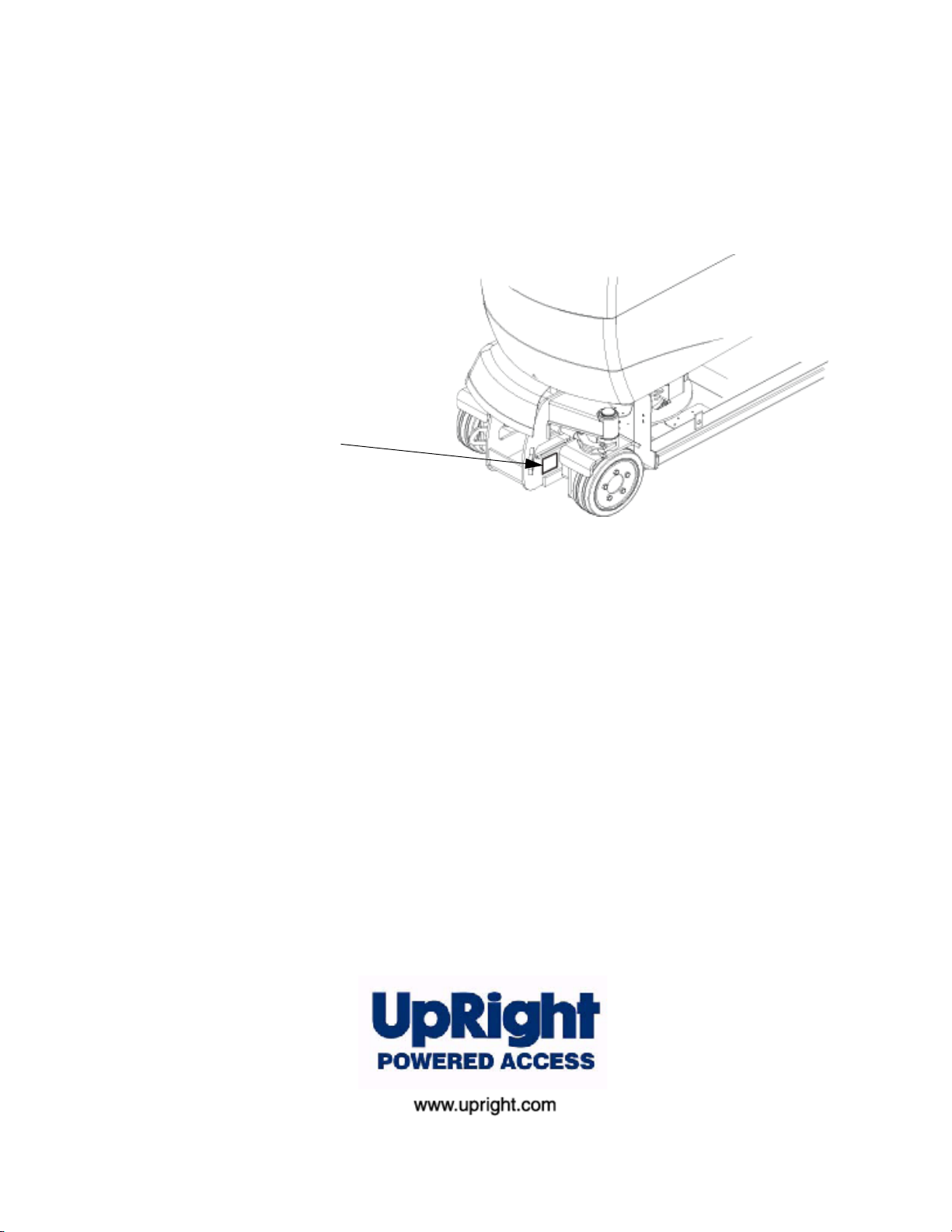
missing, the SERIAL NUMBER is also stamped
on top of the chassis above the front axle pivot.
Nameplate
The Work Platform Nameplate is located
externally at the FRONT of the chassis
When contacting UpRight for service or parts information, sure to include
the MODEL and SERIAL NUMBERS from the equipment nameplate.
The MB20N/26 work platform meets and exceeds the requirements of both:
En280:2001 and ANSI A92.5 (1999)
Page 4

Page 5

WARNING
! !
All personnel shall carefully read, understand and follow all safety rules and operating instructions
before operating or performing maintenance on any UpRight Powered Access aerial work platform.
Safety Rules
Electrocution Hazard Tip Over Hazard Collision Hazard Fall Hazard
THIS MACHINE IS NOT
INSULATED!
USE OF THE WORK PLATFORM: This aerial work platform is intended to lift persons and his tools as well as the material used
for the job. It is designed for repair and assembly jobs and assignments at overhead workplaces (ceilings, cranes, roof structures,
buildings etc.). All other uses of the aerial work platform are prohibited!
THIS WORK PLATFORM IS NOT INSULATED! For this reason it is imperative to keep a safe distance from live parts of
electrical equipment! - DO NOT get closer than the minimum distance recommended by the “National Regulations”.
Exceeding the specified permissible maximum load is prohibited! See "Specifications - Platform Capacity" for details.
The use and operation of the aerial work platform as a lifting tool or a crane is prohibited!
NEVER exceed the manual force allowed for this machine. See “Manual Force” on page 2 for details.
DISTRIBUTE all platform loads evenly on the platform.
NEVER operate the machine without first surveying the work area for surface hazards such as holes, drop-offs, bumps, curbs, or debris;
and avoiding them.
OPERATE machine only on surfaces capable of supporting wheel loads.
NEVER operate the machine when wind speeds exceed this machine’s wind rating. See “Beaufort Scale” on page 1 for details.
NEVER attach notice boards etc. to the platform, as this will increase wind loading.
IN CASE OF EMERGENCY push EMERGENCY STOP switch to deactivate all powered functions.
IF ALARM SOUNDS while platform is elevated, STOP, carefully lower platform. Move machine to a firm, level surface.
Climbing up the railing of the platform, standing on or stepping to or from the platform onto buildings, steel or prefabricated concrete
structures, etc. is prohibited!
Dismantling the entry gate or other railing components is prohibited! Always make certain that the entry gate is closed and securely
locked!
It is prohibited to keep the entry gate in an open position when the platform is raised!
To extend the height or the range by placing of ladders, scaffolds or similar devices on the platform is prohibited!
NEVER perform service on machine while platform is elevated without blocking elevating assembly.
INSPECT the machine thoroughly for cracked welds, loose or missing hardware, hydraulic leaks, loose wire connections, and damaged
cables or hoses before using.
VERIFY that all labels are in place and legible before using.
NEVER use a machine that is damaged, not functioning properly, or has damaged or missing labels.
To bypass any safety equipment is prohibited and presents a danger for the persons on the aerial work platform and in its working range.
NEVER charge batteries near sparks or open flame. Charging batteries emit explosive hydrogen gas.
Modifications to the aerial work platform are prohibited or permissible only at the approval by
AFTER USE, secure the work platform from unauthorized use by turning the keyswitch off and removing key.
The driving of MEWP’s on the public highway is subject to Regulations made under the Road Traffic Acts.
ENVIRONMENTAL TEMPERTURE LIMITATION, The machine is primarily for use in normal ambient tempertures and conditions
ranging between 50c to -20c.
NEVER elevate the platform or drive
the machine while elevated unless
the machine is on a firm, level
surface.
NEVER position the platform
without first checking for overhead
obstructions or other hazards.
UpRight Powered Access
NEVER climb, stand, or sit on
platform guardrails or midrail.
.
Page 6

NOTES:
Page 7

1. I
NTRODUCTION
S
PECIAL INFORMATION
S
PECIAL LIMITATIONS
M
ANUAL FORCE
P
LATFORM CAPACITY
B
EAUFORT SCALE
2. G
ENERAL DESCRIPTION
Figure 2. Work Platform 2 - 2
3. S
AFETY INSPECTION
Figure 3. Battery Fill Button & Valve 2 - 3
Figure 4. Lower Control Panel 2 - 4
Figure 5. Joystick 2 - 5
4. O
PERATION OF THE PLATFORM CONTROLS
U
PPER CONTROL PANEL
Figure 3. Upper Control Panel 2 - 7
C
ONTROL FUNCTIONS
Table 1. Platform Controls and Indicators 2 - 7
L
OWER CONTROL PANEL
Figure 4. Lower Control Panel 2 - 8
T
YPICAL OPERATION
C
ONTROLS AND INDICATORS
E
LEVATING
T
RAVEL WITH WORK PLATFORM LOWERED
T
RAVEL WITH WORK PLATFORM ELEVATED
E
MERGENCY SITUATIONS
E
MERGENCY LOWERING (BY HAND
& L
OWERING THE WORK PLATFORM
Figure 8. Emergency Lowering - Mast Valve 2 - 11
Figure 9. Emergency Lowering - Jib Valve 2 - 11
5. T
RANSPORTATION
M
ACHINE WEIGHTS
Figure 3. Lifting by Forklift 2 - 12
L
IFTING BY CRANE
Figure 4. Lifting by Crane 2 - 13
T
RANSPORT BY TRUCK
Figure 5. Securing the platform
T
OWING
& W
INCHING VALVES
Figure 6. Valve Block-Towing Valves 2 - 15
6. A
FTER USE
& S
TORAGE
A
FTER USE EACH DAY
H
OUR METER
L
ONG-TERM STORAGE
P
RESERVATION
Figure 3. Battery Disconnect 2 - 16
B
ATTERIES
D
AILY MAINTENANCE CHECKLIST
7. S
PECIFICATIONS
C
ONTENTS
P
AGE NUMBER
1 - 1
1 - 1
1 - 1
2 - 1
2 - 1
2 - 1
2 - 2
2 - 3
2 - 6
2 - 7
2 - 7
2 - 9
2 - 9
2 - 9
2 - 9
2 - 10
2 -10
2 - 11
)
2 - 11
2 - 12
2 - 12
2 - 13
2 - 14
2 - 14
2 - 14
2 - 15
2 - 15
2 - 16
2 - 16
2 - 16
2 - 16
2 - 17
Daily Maintenance Checklist 2 - 17
MB20N
MB26
2 - 18
2 - 18
Contents
Page 8
1.
Introduction
Section 1
1.
Introduction
1.1 I
NTRODUCTION
P
URPOSE
This Service & Parts Manual is designed to provide instructions and illustrations for the
safe operation and maintenance of the MB20N & MB26 Work Platform manufactured by
Upright Powered Access Ltd. The purpose of this machine is to provide fast and safe
DO NOT use on soft ground or on slopes greater than 2 degrees.
DO NOT use the lifting mechanism to raise or lower goods or persons except within the
cage and subject to the weight limitations.
DO NOT enter the platform from a structure, rack or other platform.
ENVIRONMENTAL TEMPERTURE LIMITATION
ambient tempertures and conditions ranging between 50c to -20c.
S
COPE
This manual includes the procedures and responsibilities for the inspection,
transportation, safe operation, maintenance, and repair of this product. The
Maintenance Section within the Parts & Service Manual also covers preventative
maintenance and troubleshooting.
S
PECIAL INFORMATION
& L
IMITATIONS
,
The machine is primarily for use in normal
Throughout this manual the users attention is drawn to these special warning boxes:
D A N G E R
! !
Indicates an imminently hazardous situation which, if not avoided, will
result in severe injury or death.
!
W A R N I N G
Indicates a potentially hazardous situation which, if not avoided,
could result in severe injury or death.
!
C A U T I O N
Indicates a potentially hazardous sit uation which, if not avoided, may
result in minor or moderate injury.
1.2 G
1 - 1
ENERAL
D
ESCRIPTION
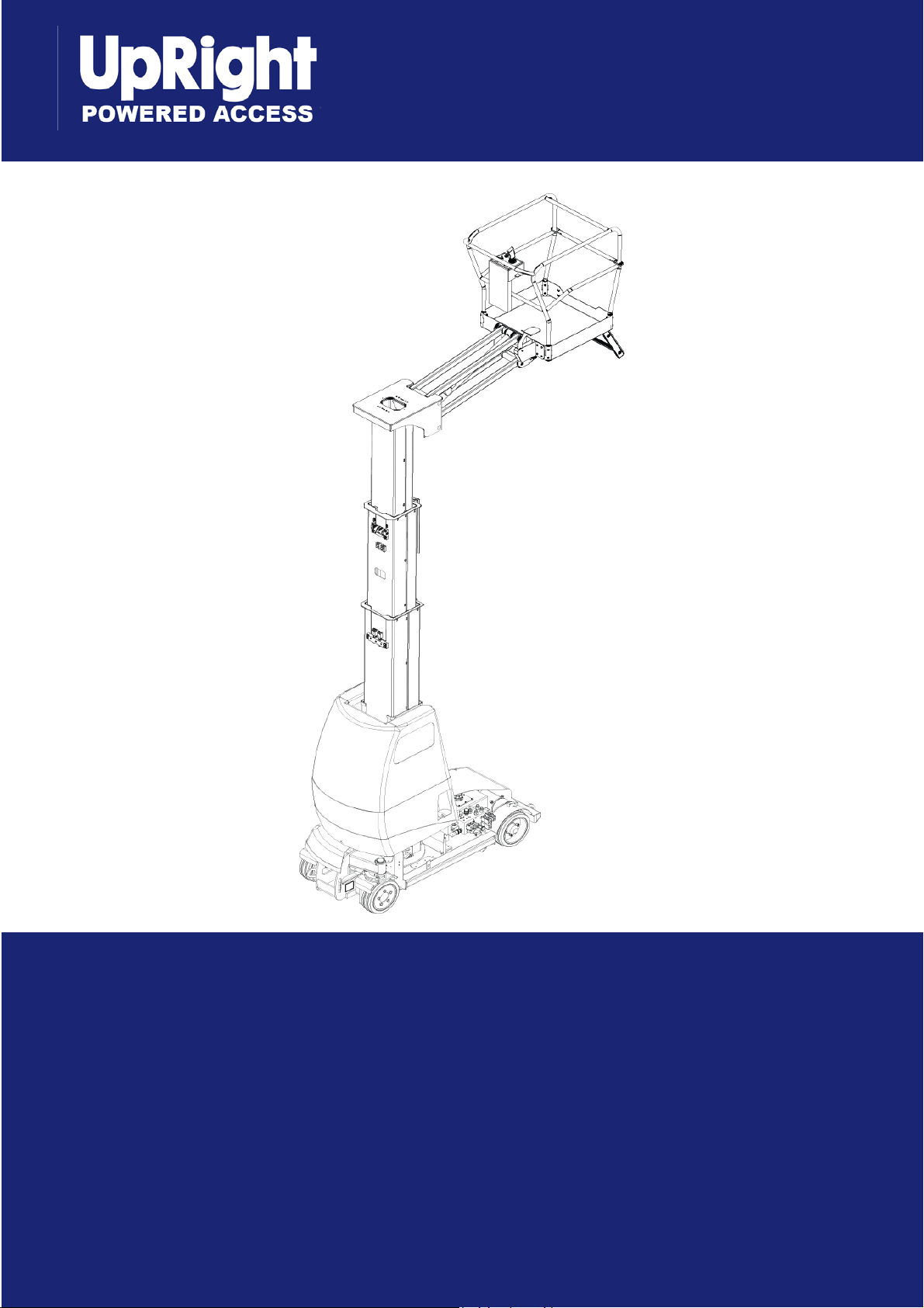
The MB20N/26 are self propelled, fast acting aerial work platforms, designed to raise two
operators with hand tools to a platform floor height of 6.00 m and 7.76 m respectively.
The accessible height is approximately 2.00 m above these figures. It is designed to
travel with safe working load and work tools up to an upper limit, See table on page
2-18 / 2-19 .
unit offers the ability to reach over obstacles but must be used on firm and level
The
ground at all times.
!
!
Page 9

1.
Introduction
P
LATFORM
The MB20N/26 platform is large enough for two operators indoors, one outdoors and
has a free-draining perforated floor with 150 mm toeboards. Hand-rails are constructed
from Steel tubing and a safety drop-bar is provided at the entrance. Safety restraint
harness anchor points are also fitted in the floor of the platform. These must be used at
all times. The main controls are fitted to this platform.
!
W A R N I N G
DO NOT use the work platform without guardrails properly
assembled and in place.
P
LATFORM
The primary (Upper) control box is permanently fitted to the front of the platform. It
features a joystick which provides proportional control for raising or lowering the mast,
raising or lowering the jib or rotating the complete mast assembly. The same joystick is
also used to drive and steer the machine.
A safety Interlock Switch or ‘deadman button’ is incorporated into the Joystick. It must
be activated at all times in order to operate any function. This feature allows for onehanded operation. A comprehensive explanation of control functions is given in the
Operators Manual - a copy of which shall be located in the platform document wallet
located just beneath the upper control station in the platform.
The secondary (Lower) control box is fitted to the mast cover at arm level. It features a
‘deadman’ enable button and selector buttons to provide pre-programmed speeds for
all functions except drive and steering. This control station is used primarily for servicetype operations including pre-operation inspection. It should never be used to position
a manned or unmanned platform. It may be used in the event of emergency, however,
to lower the manned platform.
C
ONTROLLER
!
!
W A R N I N G
NEVER operate the machine from the upper controls until the
platform entrance drop-bar is in the fully lowered position and the
safety harness is fitted.
E
LEVATING
The platform is raised and lowered by a combination of a steel jib and a series of
telescoping mast sections. The main hydraulic cylinder, mounted within the masts, lifts
the 2nd mast directly. The other masts are connected by a system of heavy duty plate
chains and pulleys to ensure sequential lifting.
A parallel system of heavy duty straps ensures that the masts descend in the proper
sequence and also ensure that a mast cannot be held in suspension by an obstacle
during descent.
The jib cylinder provides a lifting arc to the jib and cage assembly. All hydraulic
functions are carried out using solenoid operated control valves. Each cylinder features
an integral holding valve to prevent uncontrolled descent in the case of a hose bursting.
A
SSEMBLY
!
1 - 2
Page 10

1.
Introduction
R
OTATION
The complete mast, jib and cage assembly can be rotated to provide a maximum
outreach of 2.6m in the case of the MB20N and 2.96m in the case of the MB26 machine.
This dimension is measured from the centreline of rotation and is carried out by means
of an integral hydraulic motor driving a Worm Drive Unit, around a Slew Gear.
D
RIVE
P
OWER
& S
An electronic controller, mounted in the chassis, is pre-programmed to adjust the upper
speed limit of each individual function. The controller limits the rotational speed of the
electronic motor and oil pump, thereby limiting the maximum oil flow rate.
The following functions are controlled and driven by the electro-hydraulic system:
• Traction Drives (Fwd & Rev) mast stowed/mast raised.
• Steering and Jib elevation.
• Mast elevation, descent and rotation.
• The Jib descent function is gravity operated and is determined by built in flow
regulators.
S
G
EAR
TEER
YSTEM
S
YSTEM
The Power System (Prime Mover) incorporates four 6V batteries driving a 4KW electro-
hydraulic pump. The pump drives all hydraulic cylinders and the traction drive motors. A
single multi-valve control block diverts the oil pressure to the individual actuators. The
oil flow rate is limited by the pre-programmed speed setting on the motor but is
determined by the position of the joystick in the Upper Control Box.
1.3
W
ORKSHOP
Detailed descriptions of standard workshop procedures, safety
principles and service operations are not included. Note that this
manual does contain warnings and cautions against some specific
service methods that could cause personal injury, or could damage
a machine or make it unsafe.
P
ROCEDURES
All information contained in this manual is based on the latest product information
available at the time of printing. We reserve the right to make changes at any time
without notice.
No part of this publication may be reproduced, stored in retrieval system, or transmitted,
in any form by any means, electronic, mechanical, photocopying, recording, or
otherwise, without the prior written permission of the publisher. This includes text,
figures, and tables.
!
CAUTION
!
1 - 3
Please understand that these warnings cannot cover all
conceivable ways in which service, whether or not recommended
by UpRight, might be done, or of the possible hazardous
consequences of each conceivable way, nor could UpRight
investigate all such ways.
Anyone using service procedures or tools, whether or not
recommended by UpRight must satisfy themselves thoroughly that
neither personal safety nor machine safety will be jeopardized.
When in doubt, contact your local distributor or UpRight.
Page 11

2. Operation & Specifications
2. Operation & Specifications
2.1 I
NTRODUCTION
S
PECIAL LIMITATIONS
The purpose of this machine is to provide fast and safe access to difficult to reach
areas.
Refer to the Specification section for the machines access limitations.
Travel with the platform raised is limited to creep speed range.
M
ANUAL FORCE
Manual force is the force applied by the occupants to objects such as walls or other
structures outside the work platform.The maximum allowable manual force is limited to
200 N (45 lbs.) of force per occupant.
DANGER
! !
DO NOT exceed the maximum manual force.
NEVER exceed the platform capacity.
P
LATFORM CAPACITY
The Platform is designed to travel with safe working load (SWL) including work tools to
an upper limit of 215 kg (425 lbs for ANSI MB20N).
B
EAUFORT SCALE
Never operate the machine when wind speeds exceed 12.5m/s (28 m.p.h.)
[Beaufort scale 6].
W
B
EAUFORT
R
ATING
3 3,4~5,4 12,25~19,4 11.5~17.75 7.5~12.0
4 5,4~8,0 19,4~28,8 17.75~26.25 12.0~18
5 8,0~10,8 28,8~38,9 26.25~35.5 18~24.25
6 10,8~13,9 38,9~50,0 35.5~45.5 24.5~31
7 13,9~17,2 50,0~61,9 45.5~56.5 31.~38.5
M/S KM/H FT./S M.P.H
! !
DO NOT use on soft ground or on slopes greater than 2 degrees.
The work platform is NOT intended for use on uneven or rough
terrain.
ONLY operate this machine on FIRM and LEVEL ground.
IND SPEED
DANGER
G
.
Papers and thin branches move.
Flags wave.
Dust is raised, paper whirls up, and small branches
sway.
Shrubs with leaves start swaying.
Wave crests are apparent in ponds or swamps.
Tree branches move.
Power lines whistle. It is difficult to open an umbrella.
Whole trees sway.
It is difficult to walk against the wind.
ROUND CONDITIONS
2 - 1
Page 12

2. Operation & Specifications
2.2 G
ENERAL DESCRIPTION
The MB20N/26 are self propelled, fast acting aerial work platforms, designed to raise
two operators with hand tools to a platform floor height of 6.00m and 7.76m
respectively. The accessible height is approximately 2.00m above these figures.
The unit offers the ability to reach over obstacles but must be used on firm and level
ground at all times.
D A N G E R
! !
DO NOT use the lifting mechanism to raise or lower goods or persons
except within the cage and subject to the specified weight limitations.
D A N G E R
! !
DO NOT enter the platform from any structure, rack or other platform.
Figure 3: Work Platform
Elevating Assembly
Platform Controller
Safety Drop-bar
Platform
Chassis Controls
Chassis
2 - 2
!
W A R N I N G
DO NOT use the work platform without safety drop-bar in place and
with the safety harness fitted.
!
Page 13

2. Operation & Specifications
2.3 S
AFETY INSPECTION
This Safety Inspection shall be carried out by the owner immediately prior to
transporting this machine.
This Safety Inspection shall also be carried out by the user prior to use each day.
The procedure is to carry out the following 14 checks in order as follows.
1. Remove the rear chassis covers by means of the two top twist-locks and the two liftand-turn catches at the sides. The cover is removed by sliding it backwards and
upwards. Use the central handle provided.
2. Ensure that the mast and jib are fully lowered. Remove the hydraulic oil filler cap and
check that the hydraulic oil level is correct. Oil should be visible on the dip stick. Top up
as necessary using hydraulic oil Viscosity Grade ISO 46.
3. Inspect the chassis area for oil leaks, loose parts, frayed cables and hoses and
structural damage etc. Check that all cable connections to the solenoid valves are
intact.
4. Open the Inspection hatches on both sides of the upper mast cover. Check that the AC
mains cable is disconnected from the battery charger. Check the electrolyte level in
each battery cell. Top up as necessary with distilled water only.
5. Use the automated battery top-up system fill the batteries to the correct electrolyte
level. This is done by opening the shut off valve and pressing the green fill button for
approximately 10 seconds, then re-closing the shut-off valve.
Batteries should be examined for cracks, acid leakage and terminal corrosion. Take
corrective action immediately if either check fails.
Figure 3: Battery Fill Button & Valve
Battery fill Button
Shut off Valve
In CLOSED Position
!
CAUTION
!
Vehicles fitted with the automated battery top-up system with shut
off valve, top up the battery cells with distilled water using the
electrolyte fill button, ensuring that the shut-off valve is open during
the fill and closed after use.
This is the only time this valve should be opened.
2 - 3
Page 14

2. Operation & Specifications
Figure 4: Lower Control Panel
1. Emergency Stop
2. KeySwitch - Platform Controls
- OFF
- Lower Controls
3. Analogue Rocker
4. Selector Switch - Jib
- Mast
- Mast Rotate
5. Enable Switch
6. Hour Meter/Battery Capacity Indicator
6. Prior to operating the functions, check that the upper and lower emergency stop
buttons on each control station are retracted; turn clockwise if necessary. Carry out
the following function from the Lower Control Station.
NOTE: DO NOT enter the platform at this stage.
2
3
4
1
6
5
7. Check jib operation by extending the jib to its fully elevated position. Check for
correct routing of the hoses and cables. Check the Emergency Lowering feature of
the jib. Ensure that when the Emergency Lowering lever/button is disengaged, the jib
no longer descends. Return the jib to its rest position using the normal Lower Control
Station.
8. Check mast chains by elevating the masts approximately 30cm above the rest
position. Check for correct routing of the energy chain. Raise the masts to full height
and check for correct adjustment of each lifting chain as follows. Each chain in the
pair should bear load. Use a hand held spring balance or tensiometer apply a
nominal load (approximately 10kgf.) to either chain in the pair. Apply the load about
half way up the chain. Record the approximate deflection i.e. the offset distance from
the mast. Repeat the measurement on the adjacent chain at the same location.
Chains bearing equal load will deflect equal amounts. Carefully adjust the slack chain
until the deflections are approximately equal. Torque up the locknuts to 70 Nm.
NOTE: Apply a thin layer of grease to the lifting chains with a small paintbrush.
!
C A U T I O N
Over-tensioning of either lifting chain will result in unnecessary
lifting of the mast.
!
2 - 4
This will lead to a subsequent increase in machine stowed height.
Page 15

2. Operation & Specifications
The function of the mast straps is to ensure that masts descend in the correct order
and more importantly, that masts cannot continue to descend if the jib or platform
meets an external obstacle. Raise the masts about 30cm. Check the external mast
clamp screws for tightness. Pull on the short length of each strap and check that they
are secure. Refer to the maintenance manual for instructions on more stringent
periodic checks on these straps.
Check the Emergency Lowering feature of the mast. The lever is located in the upper
mast over. Open the left hand battery inspection hatch and locate the ‘Emergency
Lowering’ decal label. Check the wear pads for damage or heavy scoring. Replace as
necessary.
9. Elevate the jib fully. Using the Lower Control Station, turn the mast assembly through
about 90 degrees. Check the correct routing of the hoses and cables and the correct
smooth operation of the energy chain in its chassis base slide. Continue rotating
through 180 degrees in both directions. Confirm that the rotation stops are intact.
10. STANDARD PLATFORM CONTROLS Repeat the mast, jib and rotate functions from
the Upper Control Station in the platform. Check that pressing the emergency stop
button prevents subsequent operation of the joystick.
11. TILT SENSOR FUNCTION CHECK. The tilt sensor is incorporated in the EZ230
control module. To check it’s operation while in platrom drive the machine onto a
suitable ramp to raise it’s tilt angle above 2 degrees, lift the Jib until the jib limit switch
just separates, a continuous audible alarm should sound and all functions on the
machine become disabled. Lower the jib using the emergency manual release valve
located between the jib structure, the alarm should silence and normal operation
becomes enabled.
!
C A U T I O N
!
During manual lowering extreme care must be taken to ensure hands
are not trapped in the jib structure.
Figure 5: Joystick
Joystick
with Deadman Grip
12. MACHINE TRAVEL - UNELEVATED Travel functions are possible only from the
platform Upper Control Station. As with all such controls, the deadman handgrip switch
must be depressed before any function can operate.
Select Drive on the upper control panel. Pushing back and forward on the joystick
moves the machine backwards and forwards respectively.
The pothole protection will begin to retract immediately. However, full demand speed
will not be realised until the bars are fully raised. This takes about 3 seconds. Check
that the motion alarm DOES sound during travel. Check that the thumb operated
switches on the top of the joystick operates the front wheel steering.
13. MACHINE TRAVEL-ELEVATED While the masts are raised, it is possible to drive and
steer the machine at a much reduced speed. Also note that while the masts are raised,
the pothole protection bars should be fully extended and should remain extended
during slow speed motion of the machine.
2 - 5
Page 16

2. Operation & Specifications
The issue of reduced speed while elevated and deployment of the
pothole protection bars is crucial to the safe operation of this
machine.
The machine may not be released or operated unless these
functions operate properly.
2.4 O
!
W A R N I N G
14. FINAL PREPARATION Configure the masts and jib to the stowed position. Replace
all machine covers and secure.
NOTE: The machine is now ready for Operation or Transportation.
PERATION OF THE PLATFORM
The primary (Upper) control box is permanently fitted to the front of the platform. It
features a multi-use joystick which provides proportional control for all the machines
functions. That includes, raising or lowering the mast, raising or lowering the jib,
rotating the mast assembly, and also to drive and steer the machine.
A safety Interlock Switch or ‘deadman button’ is incorporated into the Joystick. It
must be activated at all times in order to operate any function. This feature allows for
one-handed operation.
!
C
ONTROLS
The secondary (Lower) control box is fitted to the mast cover at arm level. It features
an enable button and selector buttons to provide pre-programmed speeds for all
functions except drive and steering. This control station is used primarily for servicetype operations including pre-operation inspection. It should never be used to
position a manned or un-maned platform.
NOTE: It may be used in the event of emergency to lower the manned platform.
!
W A R N I N G
NEVER operate the machine from the upper controls until the
platform entrance drop-bar is in the fully lowered position and the
safety harness is fitted.
!
TO TURN THE MACHINE ON
Turn the key switch on the lower controls panel to platform controls or lower
controls as required, the overload warning lamp on the platform control box
will flash for 2 seconds and the buzzer will sound twice confirming that the
overload sensor has booted up.
2 - 6
C
ONTROLS AND INDICATORS
The pre-operation safety checks should be carried out prior to operation. These
checks are detailed in the previous section. Operators who follow these guidelines
will become familiar with the controls and indicators on the machine.
This section summarises the controls and indicators in tabular form and provides
more detailed information.
Page 17

2. Operation & Specifications
!
W A R N I N G
DO NOT operate the machine from the upper controls until the
platform entrance drop-bar is in the fully lowered position and your
safety harness has been fitted and attached.
U
PPER CONTROL PANEL
6.Mast Select Button
3.Emergency Stop
8. Horn
5.Selector Switch
!
2. Dead Man Grip(Trigger)
Figure 3: Upper Control Panel
7.Low/High
Torque Selector
4. Steering
Switch
9. Low Battery Warning
10. Overload Warning Light
1. Joystick (forward/back)
C
ONTROL FUNCTIONS
Table 1: Platform Controls and Indicators
I
TEMS
1 Joystick
2 Deadman Grip
3 Emergency Stop
N
AMES
F
UNCTION
Refer to the decal logic diagrams for correct direction of
motion.
e.g. If Drive is preselected - pushing forward moves
machine forward.
The ‘Deadman’ grip switch on the joystick must be
grasped for any function to operate.
Push this red button at any time to isolate power.
Turn clockwise to reset.
2 - 7
Page 18

2. Operation & Specifications
I
TEMS
N
AMES
4 Steering Switch Turns the wheels left or right.
F
UNCTION
5 Selector Switch
6
7
8
9
10
Drive / Lift Selector
Low / High Torque Selector
Horn Button
Low battery warning lamp
Overload warning lamp Illuminates when load in basket exceeds SWL
Pre selects Jib, Mast or Mast Rotate function.
Pre selects either drive or lift function.
In drive function pre-selects low torque high speed drive
or high torque low speed drive, only functions when mast
and jib are down.
Use to warn bystanders or to attract attention.
Illuminates when battery charge is low and machine
automatically switches into limp mode.
Table 2: Lower controls and Indicators
L
OWER CONTROL PANEL
I
TEMS
1
N
AMES
Emergency Stop
F
UNCTION
Push this red button at any time to isolate power.
Turn clockwise to reset.
2 Key Switch Selects Platform controls, OFF, or lower controls.
3
4
5
Rocker Switch
Selector Switch
Enable Switch
Activates the Pre-Selected operation, in either direction.
Pre-selects Jib, Mast or Mast Rotate function.
This Switch Enables the rocker switch and must be
held up during operation.
6
Hour Meter / BCI
Displays total run time of the machine and an indication
of remaining battery capacity.
2 - 8
Page 19

2. Operation & Specifications
Figure 4: Lower Control Panel
1. Emergency Stop
2. KeySwitch - Platform Controls
- OFF
- Lower Controls
3. Analogue Rocker
4. Selector Switch - Jib
- Mast
- Mast Rotate
5. Enable Switch
6. Hour Meter/Battery Capacity Indicator
T
YPICAL OPERATION
Raising the mast.
• The Keyswitch must be turned to lower controls (2).
• Select Mast using the selector switch (4)
• Press up and hold the switch (5),
• Activate the Rocker Switch (2) in the direction required.
1
2
6
3
4
5
E
LEVATING
Before operating the MB20N Work Platform it is imperative that the pre-operation Safety
Inspection has been completed and any deficiencies have been corrected. The
operator must also be fully trained in the use of this machine.
Before beginning any operation, the following checks should be carried out.
!
W A R N I N G
ENSURE that no other persons are within 1 metre of the machine.
Be aware of the pothole protection bar hazard on both sides of the
machine.
LOOK up and around for obstructions before performing the lift or
drive functions.
DO NOT overload the platform.
DO NOT operate near electrical power cables, keep within national
safety limits.
THIS WORK PLATFORM IS NOT ELECTRICALLY INSULATED.
NOTE: Chassis controls are for service use only.
& L
OWERING THE
!
W
ORK PLATFORM
2 - 9
Page 20

2. Operation & Specifications
1. Ensure that the Key Switch on the Lower Control Box is turned to the Platform Controls
position and both emergency stop buttons are off (twist clockwise if necessary).
2. Check the Display B.C.I. is illuminated. If not, the battery may need recharging.
3. Enter the Platform through the entrance at the rear of the MB20N/26 and ensure that
the drop bar is in position. Raise and lock the entry step.
4. Before using the machine all local Safety Regulations involving helmets and
restraining devices should be observed. Safety harness lanyards, not exceeding 1
metre in length, should be attached to anchor points in cage floor.
5. Check if the audible alarm sounds due to un-level ground. None of the functions can
work if the machine is not level.
T
RAVEL WITH
Refer to Tables 1 & 2 for controls and indicators.
1. Verify that both Lower and Upper Control Console Emergency Stop Button is in the
‘ON’ position (turn clockwise to reset).
W
ORK PLATFORM LOWERED
2. Turn the key switch on the lower control panel to the platform controls position.
3. Climb into the Platform and select drive using the drive / lift selector toggle switch.
Ensure that the drop bar is in position.
4. Check that the route is clear of persons, obstructions, pot holes or ledges and is
capable of supporting the wheel loads. Also, check that the clearances above, below,
and to the side of the Work Platform are sufficient.
5. To steer the MB20N/26, activate the Deadman Switch while pushing the Steering
Thumb-switch, on top of the Joystick, LEFT or RIGHT to turn the wheels. Observe
the tyres while manoeuvring to ensure correct direction.
NOTE: Steering is not self-centring. The wheels must be returned to the straight ahead
position by operating the Steering Switch.
T
RAVEL WITH
If the machine stops driving and the Tilt Alarm sounds, lower the
Platform immediately.
Using the Emergency Override functions, move the machine to a
level location before re-elevating the platform.
W
ORK PLATFORM ELEVATED
!
C A U T I O N
!
2 - 10
Travel with platform elevated ONLY on firm and level surfaces.
Refer to Tables 1 & 2 for controls and indicators.
NOTE: The Work Platform will travel at reduced speed when in the elevated position.
1. Check that the route is clear of persons, obstructions, pot holes or ledges and is
capable of supporting the wheel loads. Also, check that the clearances above, below
and to the side of the Work Platform are sufficient.
2. Ensure that the pothole guards remain in the extended (down) position during
elevated travel.
Page 21

2. Operation & Specifications
E
MERGENCY SITUATIONS
In any emergency situation, the immediate action is to push the red “Emergency Stop”
button. This will instantly cut of all electrical power to the controls. The button must be
twisted in a clockwise direction in order to recommence control.
However, the switch should be reset only when it is safe to do so.
If the Continuous Audible warning alarm sounds, normal control functions will cease to operate.
This will be due to the following problem;
• The Tilt Sensor has been activated
E
MERGENCY LOWERING (BY HAND
)
!
C A U T I O N
During manual emergency lowering, extreme care must be taken
to ensure that the person carrying out the task is not struck by the
jib or platform structure.
Should the machine become inoperable when elevated request a person on the
ground to lower the platform using the emergency lowering valves. Lower the mast
structure before lowering the jib/platform structure.
NOTE:Lower the masts fully before lowering the jib structure.
Locate the red lever behind the
mast cover inspection door on the
left hand side of the machine. By
pushing the lever up, the mast will
descend fully under gravity.
Releasing the spring-loaded lever
will cease this operation
immediately if required.
!
Figure 8: Emergency Lowering - Mast Valve
Figure 9: Emergency Lowering - Jib Valve
The Jib may be manually lowered
by operating the manual release
valve located between the Jib
Structure.
M
ANUAL ROTATION
1. Lower the masts and jib fully before manually slewing the assembly. Press the
Emergency Stop Button to prevent inadvertent powered motion.
2. Locate the opening behind the front right drive wheel. Apply a 23 mm socket wrench
with extension bar to the shaft and turn to rotate the elevating assembly. (Turning the
front wheel fully to one side will facilitate this operation).
2 - 11
Page 22

2. Operation & Specifications
2.5 T
RANSPORTATION
M
ACHINE
Before transporting or lifting the MB20N/26 machine be aware of its weight. It is very
important to realise that the centre of gravity of the stowed machine is approximately
80 cm above ground and in the plane of the energy chain which is located on the
back of the mast.
MB20N CE Version= 2590 kg
MB20N US Version= 3012 kg (6640 lbs)
MB26 CE Version = 2660 kg
MB26 US Version = 3175 kg (7000 lbs)
In cases of particular difficulties with lifting or shipping it is possible to remove the
single block ballast from the machine. Remove the 13 screws connecting the ballast
cover to the mast. Undo the 4 bolts connecting the ballast to the mast and use a
forklift to remove the ballast block. The ballast block weighs 600 kg on MB20N, 460 kg
on MB26 ( CE version ) and 1300kg on the US (ANSI) version.
!
W A R N I N G
This work must not be carried out without the prior written permission
of UpRight Powered Access.
W
EIGHTS
!
L
IFTING BY FORK-LIFT
D A N G E R
! !
Forklifting is for transport only. See machine weights and ensure that
the forklift is of adequate capacity.
Adjust the forks so that
the minimum clearance
between them is 800mm
as shown.
Approach the machine
from either side but place
the fork as close as
possible to the front wheel
as shown.
Front
Figure 3: Lifting by Forklift
2 - 12
800mm
Page 23

2. Operation & Specifications
1. Never approach the MB20N from the front or rear while fork lifting.
2. Use maximum forklift tilt as soon as possible when raising the MB20N/26.
3. If travelling over sloped or uneven ground it is strongly recommended to temporarily tie
the MB20N jib mount structure to the forklift mast as a safety precaution.
4. The MB20N/26 may be lifted by forklift subject to the following strict procedure.
5. Ensure tha
retracted (raised).
L
IFTING
The MB20N/26 may be lifted by an overhead hoist/crane subject to the following strict
procedure.
Raise the jib to clear the lifting straps as shown.
Use 4 separate lifting straps connected to a spreader beam. DO NOT use a lesser
number of threaded straps as these could slip and lead to instability. The
recommended minimum capacity of EACH of the 4 straps is 2 tonne and the minimum
length of each strap is 2 metres. Damage to the covers and/or cage rails can occur if a
spreader beam is not deployed during a crane lift.
Apply the straps via 2
tonne shackles to each
of the 4 lifting lugs on
the chassis.
t the mast and jib are fully stowed and that the pothole bars are fully
BY C
RANE
Figure 4: Lifting by Crane
!
CAUTION
DO NOT apply lifting straps to any other part of the machine.
!
2 - 13
Page 24

2. Operation & Specifications
T
RANSPORT BY TRUCK
The MB20N/26 can be carried on a suitably rated transportation vehicle or trailer.
Because of its high gradeability, the machine can be driven under its own power on to
a standard loading ramp (Up to 14 degrees).
It is recommended to reverse the machine up on to the truck thus forward travelling
down the ramp at the delivery point. Winch-assisted loading is allowable for larger
slopes, however, operate the trucks assist winch at minimum speed to avoid overpressurising the hydraulic system in the machine.
When the MB20N/26 is on the truck or trailer it should then be made secure by:-
1. Chocking the wheels.
2. Securing with adequate chains or straps to the lifting lugs on the chassis.
!
C A U T I O N
DO NOT loop straps through the cage, ladder or jib as this could
cause permanent structural damage during transportation.
!
Figure 5: Securing the Platform
2 - 14
T
OWING
The fail-safe brakes are automatically applied when the machine comes to a stop or
in the event of total power loss due to low battery or malfunction of the hydraulic drive
system.
To tow the vehicle or to winch it on to a truck it is necessary to hydraulically bypass
the control valves and release these brakes.
Make sure the Jib is tied down securely during transport, DO NOT over tighten
straps. Straps should have adequate slack so no downward force is applied to the Jib.
& W
INCHING VALVES
Page 25

2. Operation & Specifications
Proceed as follows:- (Refer to the valve block drawing Figure 6.)
1. Fully lower the jib boom and the mast sections. Rotate the mast into the stowed
position.
2. Turn the Upper Control Box Keyswitch to the OFF position and remove the key.
3. Remove the rear GRP cover from the chassis and locate the hydraulic control valve
block.
4. The hand valve marked ‘A’ should be turned fully clockwise to close. The hand valve
marked ‘B’ should be turned fully anti-clockwise to open.
5. Operate the red handpump a number of times to develop sufficient pressure to
‘separate’ the internal brake disks. These brakes are integral with the hydraulic drive
motors.
NOTE: The machine can now be safely towed or winched.
6. On completion of towing/winching, reverse the position of the rotary hand valves ‘A’
and ‘B’. The handpump becomes inoperative when the valves are returned to their
normal position.
Figure 6: Valve Block-Towing Valves
!
2.6 A
!
W A R N I N G
RISK OF SERIOUS INJURY. Releasing the brakes will cause the
machine to move uncontrollably on a slope. Damaging momentum
can be developed due to the large mass of a slow moving machine
FTER
U
SE
A
& S
FTER
TORAGE
U
SE EACH DAY
1. Ensure that the platform (masts and jib) are fully lowered.
2. Park the machine on firm and level ground, never on a grass surface.
3. Turn the key switch to the OFF position and remove.
4. Put the batteries on charge.
B
ATTERY
C
HARGING
Before charging check that:-
1. The correct mains voltage and current is available to the charger.
The MB machine is fitted with a high output charging assembly. this consists of
two 24V 30A 900W Chargers. The chargers can be linked together if the supply
voltage and current are high enough to meet the power demand. If the power
supply is not good enough, a single charger can be used. If this option is taken,
it is important that charger ‘A’ is used, as it is the one linked to the remote display
for battery charge level.
Handpump
LED Remote
Charge indicator.
2. Check that the extension cord(s) is in good condition and is no longer than
8M (26fT). 1.5mm Sq (12 AWG) or larger cable is required. Ensure that the plug(s)
is of the correct rating and is compatible with the electrical installation into which
it will be plugged.
3. The charger(s) will turn on automatically after going through a self test sequence.
the remote LED on the control Panel will indicate the status of charging.
‘A’
2 - 15
Page 26

2. Operation & Specifications
L
ONG-TERM STORAGE
P
RESERVATION
1. Clean and touch up damaged paint surfaces.
2. Fill the hydraulic tank to operating level with the platform fully lowered. Fluid should
be visible on the tank dip stick.
3. Coat exposed portions of cylinder rods with a preservative such as multipurpose
grease and wrap with barrier material.
4. Coat all exposed un-painted metal surfaces with a light oil or other preservative.
5. Cover the machine with tarpaulin if possible. If this is not available it is advisable to
cover the mast and jib mount area as a minimum. This will prevent moisture from
entering the mast, battery and chassis areas.
Figure 3: Battery Disconnect
B
ATTERIES
1. Disconnect the batteries at the quick connect plug and socket. This is located in the
chassis between the controller and the hydraulic tank.
2. Disconnect the battery leads and tape up the lead terminals to ensure insulation.
Better battery life and efficiency is achieved if the batteries are used consistently. It is
therefore recommended that the batteries are used elsewhere if the machine is to be
unused for an extended period (2 weeks or more).
!
W A R N I N G
RISK OF SERIOUS INJURY. Take particular care when handling
batteries. Acid spills can cause severe burns or blindness.
!
Battery disconnect
is located behind the
controller
2 - 16
DO NOT store batteries close to naked flames or close to steel
fabrication areas.
Page 27

2. Operation & Specifications
D
AILY
P
REVENTATIVE
Daily preventative maintenance will prevent abnormal wear and prolong the life of
all systems. The inspection & maintenance schedule should be performed at the
specified intervals.
Inspection and maintenance shall be performed by personnel who are trained and
familiar with mechanical and electrical procedures.
M
AINTENANCE
C
HECKLIST
!
W A R N I N G
!
Before performing preventative maintenance, familiarize yourself with
the operation of the machine.
Always block the elevating assembly whenever it is necessary to
perform maintenance while the platform is elevated.
This Daily checklist has been designed for machine service and maintenance.
Please photocopy this page and use the checklist when inspecting the machine
P
M
AINTENANCE TABLE KEY
Y = Yes/Acceptable
N = No/Not Acceptable
R = Repaired/Acceptable
REVENTATIVE MAINTENANCE REPORT
Date: _______________________________________
Owner: _____________________________________
Model No: ___________________________________
Serial No: ___________________________________
Serviced By: _________________________________
.
C
OMPONENT
B
ATTERY
C
HASSIS
C
ONTROL CABLE
C
ONTROLLER
D
RIVE MOTORS
E
LEVATING ASSEMBLY
E
MERGENCY LOWERING
H
P
T
Table 1: Daily Maintenance Checklist
S
YSTEM
E
NTIRE UNIT
H
YDRAULIC FLUID
H
YDRAULIC PUMP
YDRAULIC SYSTEM
L
ABELS
LATFORM DECK AND
AILS
R
YRES AND WHEELS
Check electrolyte level.
Check battery cable condition.
Check hoses for pinch or rubbing points.
Check welds for cracks.
Check the exterior of the cable for pinching, binding or wear.
Check switch operation.
Check for operation and leaks.
Inspect for structural cracks.
Operate the emergency lowering valve & check for serviceability.
Check for and repair collision damage.
Check fluid level.
Check for hose fitting leaks.
Check for leaks.
Check for peeling, missing, or unreadable labels & replace.
Check welds for cracks.
Check for damage.
I
NSPECTION OR SERVICE
Y N R
2 - 17
Page 28

2. Operation & Specifications
S
PECIFICATIONS
MB20N
P
ARAMETER
MB20N EU V
ERSION
MB20N US V
ERSION
Duty Cycle
Platform Size
Maximum Platform Capacity
Indoors
Outdoors
Max Wind Speed
Max Manual Force Per Person
Maximum Chassis Inclination
Heights:
Maximum Platform Height
Maximum Working Height
Platform Height at Maximum Outreach
Maximum Working Outreach
Stowed Dimensions:
Length
Width
Height
Chassis Ground Clearance
Wheelbase x Wheel Gauge
Rotation
Gross Vehicle Weight
Maximum Drive Speed - Stowed
Maximum Drive Speed - Elevated
Maximum Gradeability
Outside Turning Radius
45%over 8 hour cycle
770mm x 730mm
215kg.
2 People 2 People
1 Person
12 m/s
200N
2° 2°
6.10m
8.10m
5.04m
2.64m
2.430m
0.810m
2.013m
90mm
1465mm x 708mm
360deg non-continuous
2590kg.
3.30 km/h
0.60km/h
25%
1.90m
35%over 8 hour cycle
30.5in. x 28.5in.
425lbs.
2 People
26.8 mph
45lbs
20.00ft.
26.50ft.
16.54ft.
8.66ft
7.97ft.
32in.
6.60ft
3.54in.
4.81ft. x 2.32ft.
360 deg non-continuous
6640lbs.
2.05mph.
0.37mph
25%
6.23ft.
Electrical:
Power Source
System Voltage
Battery Charger ( 2 Per Machine )
Control System
Hydraulic System:
System Relief Setting
Hydraulic Oil Type
Hydraulic Tank Capacity
Brakes
Wheel & Tyres 13.5in. x 4.0
Wheel loading
Vibration of this machine does not exceed
Noise Pressure Level
2 - 18
4 x 6V @ 375Ah Battery
24 Volt DC
24V x 30A, Output
Auto Select AC input
100-240v -50/60Hz 12-6A
Single Joystick, Function
Selector, DC Motor Controller
220bar
ISO VG46
20 litres
Spring applied hydraulically
released
solid, Non-Marking
1300kg per wheel
2.5m/sec х² 2.5m/sec х²
68dB (A) at Control Station 68dB (A) at Control Station
4 x 6V @ 375Ah Battery
24 Volt DC
24V x 30A, Output
Auto Select AC input
100-240v -50/60Hz 12-6A
Single Joystick, Function
Selector, DC Motor Controller
3190psi
ISO VG46
5.3 gallons (U.S.)
Spring applied hydraulically
released
13.5in. x 4.0
solid, Non-Marking
3466lbs per wheel
Page 29

2. Operation & Specifications
S
PECIFICATIONS
MB26
P
ARAMETER
MB26 EU V
ERSION
MB26 US V
ERSION
Duty Cycle
Platform Size
Maximum Platform Capacity
Indoors
Outdoors
Max Wind Speed
Max Manual Force Per Person
Maximum Chassis Inclination
Heights:
Maximum Platform Height
Maximum Working Height
Platform Height at Maximum Outreach
Maximum Working Outreach
Stowed Dimensions:
Length
Width
Height
Chassis Ground Clearance
Wheelbase x Wheel Gauge
Rotation
Gross Vehicle Weight
Maximum Drive Speed - Stowed
Maximum Drive Speed - Elevated
Maximum Gradeability
Outside Turning Radius
45%over 8 hour cycle
770mm x 730mm
215kg.
2 People 2 People
1 Person
12 m/s
200N
2° 2°
7.75m
9.75m
6.51m
3m 10ft.
2.800m
1.010m
2.010m
90mm
1465mm x 890mm
360deg non-continuous
2660kg.
3.13 km/h
0.60km/h
25%
1.93m
35%over 8 hour cycle
30.5in. x 28.5in.
475lbs.
2 People
26.8 mph
45lbs
25.45ft.
32.00ft.
21.36ft.
9.2ft.
40in.
6.59ft.
3.54in.
4.81ft. x 2.93ft.
360 deg non-continuous
7000lbs.
1.94mph.
0.37mph
25%
6.33ft.
Electrical:
Power Source
System Voltage
Battery Charger ( 2 Per Machine )
Control System
Hydraulic System:
System Relief Setting
Hydraulic Oil Type
Hydraulic Tank Capacity
Brakes
Wheels & Tyres
Wheel loading
Vibration of this machine does not exceed
Noise Pressure Level
4 x 6V @ 375Ah Battery
24 Volt DC
24V x 30A, Output
Auto Select AC input
100-240v -50/60Hz 12-6A
Single Joystick, Function
Selector, DC Motor Controller
220bar
ISO VG46
18 litres
Spring applied hydraulically
released
13.5in x 4.0
solid, Non-Marking
1300kg per wheel
2.5m/sec х² 2.5m/sec х²
68dB (A) at Control Station 68dB (A) at Control Station
4 x 6V @ 375Ah Battery
24 Volt DC
24V x 30A, Output
Auto Select AC input
100-240v -50/60Hz 12-6A
Single Joystick, Function
Selector, DC Motor Controller
3190psi
ISO VG46
4.7 gallons (U.S.)
Spring applied hydraulically
released
13.5in x 4.0
solid, Non-Marking
3566lbs per wheel
2 - 19
Page 30

2. Operation & Specifications
N
OTES
:
2 - 20
Page 31

Page 32

Local Distributor:
Lokaler Vertiebshändler:
Distributeur local:
El Distribuidor local:
Il Distributore locale:
USA
TEL: +1 (559) 443 6600
FAX: +1 (559) 268 2433
Europe
TEL: +44 (0) 845 1550 058
FAX: +44 (0) 195 2299 948
www.upright.com
 Loading...