

Page 1
OPERATORS
MANUAL
Part Number 512437-000-EN
Serial Number 000001 and after
January 2013
Page 2

Page 3
M1230E
ENGLISH
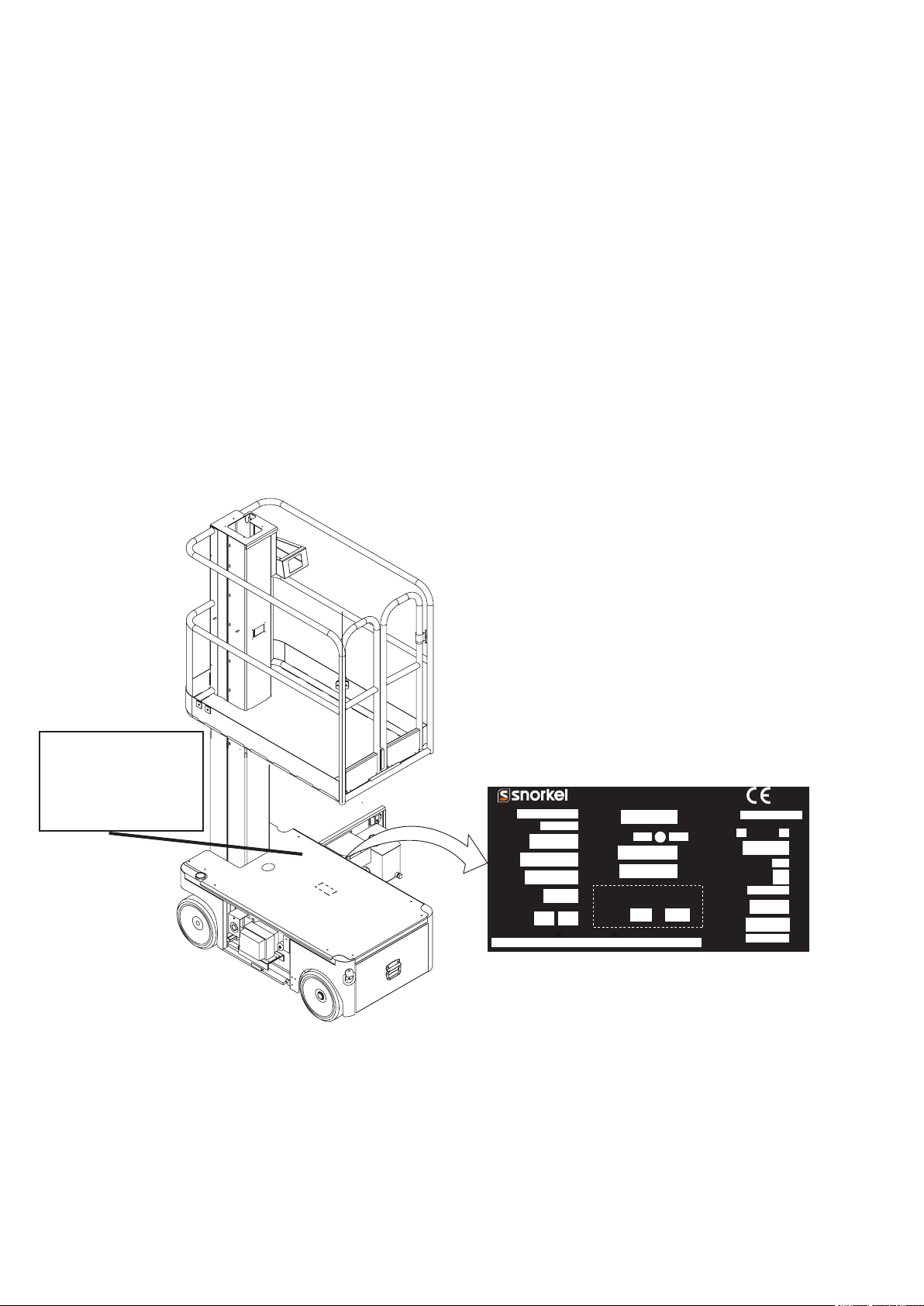
When contacting SNORKEL for service or parts information, be sure to include the MODEL and SERIAL NUMBERS from the
equipment nameplate. Should the nameplate be missing, the SERIAL NUMBER is also stamped on top of the chassis above
the front axle pivot.
Stamped Serial Number
on Chassis
MODEL
NUMBER
MONTH / YEAR
OF MANUFACTURE
NON-LOADED
MACHINE
WEIGHT
ENGINE
POWERED
MODELS
MAXIMUM
OUTRIGGER
LOAD
MAXIMUM
GRADEABILITY
Indoors
MAXIMUM
ALLOWABLE
MANUAL FORCE
(SIDE PULL)
ONLY trained and authorised personnel may operate this machine.Consult the Operation Manual before using this machine.
DO NOT make any changes to this machine, any changes made will invalidate the manufactures warranty and may contravene legislation.
www.snorkellifts.com
------
------
lbs
kg
hp
------
kW
lbs
------
kg
%
Outdoors
lbs
------
N
CAUTION
Snorkel,
Vigo Centre, Birtle y Road,
Washington, Tyne & Wear,
NE38 9DA, U.K.
MAXIMUM
PLATFORM
HEIGHT
Indoors
RATED NUMBER
OF OCCUPANTS
MAXIMUM
DRIVE
HEIGHT
MAXIMUM
PLATFORM
LOAD
Axle weights wi th machine in
the stowed posi tion.
STEER AXLE
-----
-----
DRIVE AXLE
------
Outdoors
hole
------
lbs
lbs
m
ft
m
kg
kg
ASSEMBLED IN
NUMBER
SLOPE SENSOR ALARM SETTING
FRONT
SIDE
deg
TO BACK
TO SIDE
MAXIMUM
WHEEL
LOAD
BATTERY
POWERED
MODELS
CHARGER
INPUT
MAXIMUM
ALLOWABLE
WIND SPEED
MAXIMUM
PLATFORM
REACH
DRIVE
MOTORS
BATTERIES
------
-----
----N/A
510899-001
deg
lbs
kg
V
V
Ah
V
mph
m/s
ft
m
SERIAL
ft
Page 4
2. OPERATION MANUAL
WARNING
All personnel shall carefully read, understand and follow all safety rules and operating instructions before
operating or performing maintenance on any SNORKEL.
Safety Rules
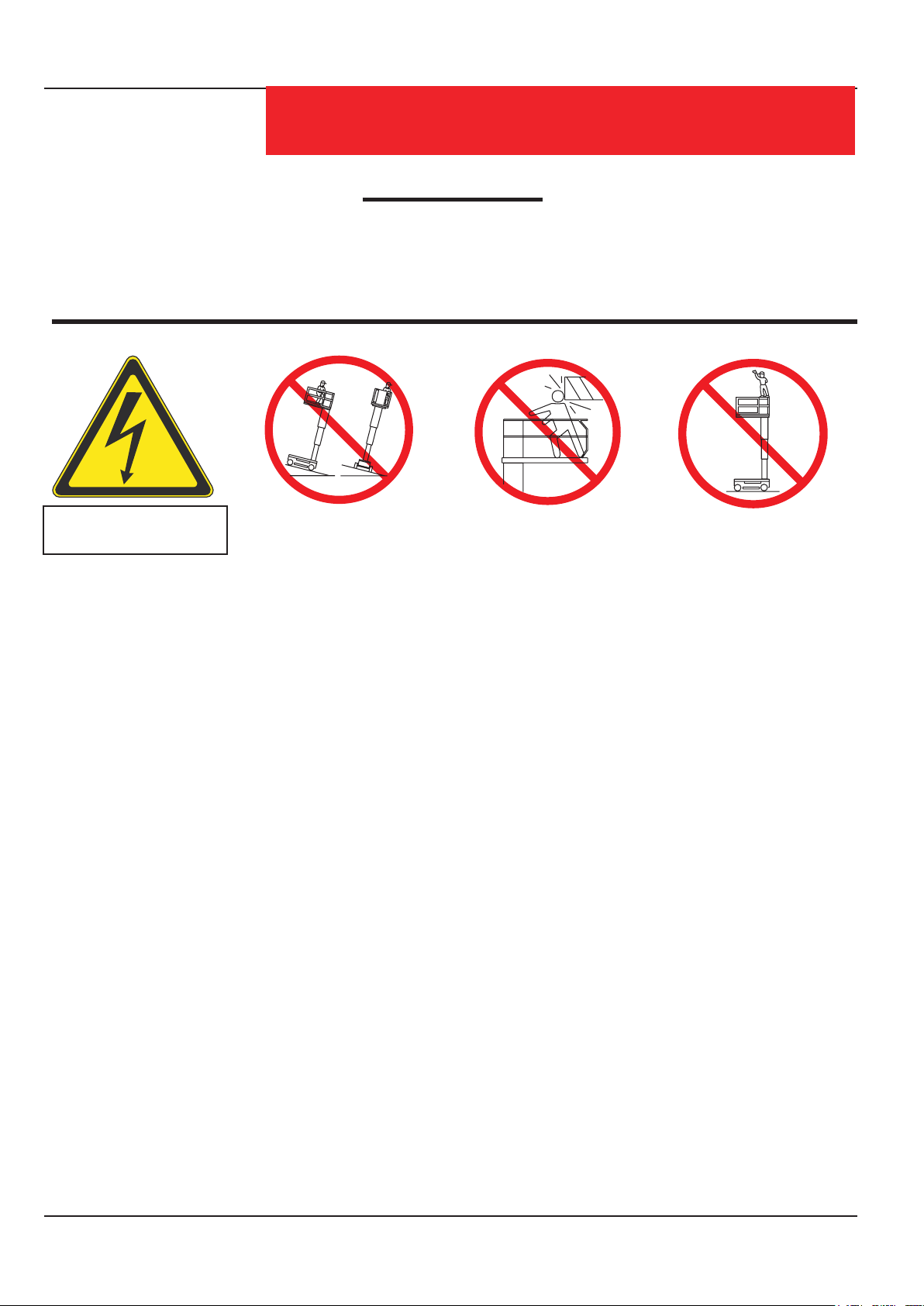
Electrocution Hazard Tip Over Hazard Collision Hazard Fall Hazard
THIS MACHINE IS NOT
INSULATED!
USE OF THE AERIAL WORK PLATFORM: This aerial work platform is intended to lift persons and his tools as well as the material
used for the job. It is designed for repair and assembly jobs and assignments at overhead workplaces (ceilings, cranes, roof
structures, buildings etc.). All other uses of the aerial work platform are prohibited!
THIS AERIAL WORK PLATFORM IS NOT INSULATED! For this reason it is imperative to keep a safe distance from live parts of
electrical equipment! DO NOT get closer than the minimum distance recommended by the “National Regulations”.
Exceeding the specied permissible maximum load is prohibited! See “Platform Capacity” on page 4 for details.
The use and operation of the aerial work platform as a lifting tool or a crane is prohibited!
NEVER exceed the manual force allowed for this machine. See “Manual Force” on page 4 for details.
DISTRIBUTE all platform loads evenly on the platform.
NEVER operate the machine without rst surveying the work area for surface hazards such as holes, drop-offs, bumps, curbs, or
debris; and avoiding them.
OPERATE machine only on surfaces capable of supporting wheel loads.
NEVER operate the machine when wind speeds exceed this machine’s wind rating. See “Beaufort Scale” on page 4 for details.
NEVER attach notice boards etc. to the platform, as this will increase wind loading.
IN CASE OF EMERGENCY push EMERGENCY STOP switch to deactivate all powered functions.
IF ALARM SOUNDS while platform is elevated, STOP, carefully lower platform. Move machine to a rm, level surface.
Climbing up the railing of the platform, standing on or stepping from the platform onto buildings, steel or prefab concrete structures,
etc., is prohibited!
Dismantling the entry gate or other railing components is prohibited! Always make certain that the entry gate is closed and
securely locked!
It is prohibited to keep the entry gate in an open position when the platform is raised!
To extend the height or the range by placing of ladders, scaffolds or similar devices on the platform is prohibited!
NEVER perform service on machine while platform is elevated without blocking elevating assembly.
INSPECT the machine thoroughly for cracked welds, loose or missing hardware, hydraulic leaks, loose wire connections, and
damaged cables or hoses before using.
VERIFY that all labels are in place and legible before using.
NEVER use a machine that is damaged, not functioning properly, or has damaged or missing labels.
To bypass any safety equipment is prohibited and presents a danger for the persons on the aerial work platform and in its working
range.
NEVER charge batteries near sparks or open ame. Charging batteries emit explosive hydrogen gas.
Modications to the aerial work platform are prohibited or permissible only at the approval by Snorkel.
AFTER USE, secure the work platform from unauthorized use by turning the keyswitch off and removing key.
(continued over page).
NEVER elevate the platform or drive
the machine while elevated unless the
machine is on a firm, level surface.
NEVER position the platform
without first checking for overhead
obstructions or other hazards.
NEVER climb, stand, or sit on
platform guardrails or midrail.
Page 4Operation Manual
Page 5
Harness attachment points are provided in the platform and the manufacturer recommends the usage of a fall
Safety Rules
restraint harness, especially where required by national safety regulations.
All harness attachment points on SNORKEL vehicles have been tested with a force of 3,650 lbs (16.3 KN)
per person.
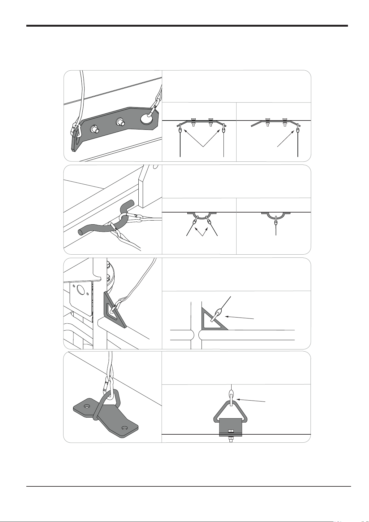
See below examples of harness attachment points used on SNORKEL vehicles with their corrosponding rating;
Harness attachment point Type 1. is rated for one
lanyard attachment per loop as shown in the
illustrations depending upon platform occupancy rating
(see operators manual & decals).
Top View Top View
Top View
Type 1.
Type 2.
2 lanyard
attachments
Harness attachment point Type 2. is rated for two
lanyard attachments per loop as shown in the
illustrations depending upon platform occupancy rating
(see operators manual & decals).
Top View
2 lanyard
attachments
Harness attachment point Type 3. is rated for one
lanyard attachment per loop as shown in the
illustrations depending upon platform occupancy rating
(see operators manual & decals).
Front View
1 lanyard
attachment
Top View
1 lanyard
attachment
1 lanyard
attachment
Type 3.
Harness attachment point Type 4. is rated for one
lanyard attachment per loop as shown in the
illustrations depending upon platform occupancy rating
(see operators manual & decals).
1 lanyard
attachment
Type 4.
NOTE: There can be more harness attachment points per machine than the
maximum number of occupants allowed in a platform. Refer to
the platform decal & specifications table listed in the operators
manual for the correct occupancy rating before use.
Operation ManualPage 1
Page 6

CONTENTS
Introduction ..................................................................................................................................................3
General .......................................................................................................................................................... 3
Special Limitations .....................................................................................................................................4
Platform Capacity ...................................................................................................................................... 4
Manual Force ............................................................................................................................................ 4
Beaufort Scale ...........................................................................................................................................4
Controls and Indicators .............................................................................................................................. 5
Pre-Operation Safety Inspection ................................................................................................................5
System Function Inspection .....................................................................................................................6
Operation ......................................................................................................................................................7
Travel With Platform Lowered ..................................................................................................................7
Steering .................................................................................................................................................... 7
Elevating Platform .................................................................................................................................... 7
Travel With Platform Elevated ..................................................................................................................7
Lowering Platform .................................................................................................................................... 7
Emergency Lowering ................................................................................................................................8
Parking Brake Release .............................................................................................................................8
After Use Each Day ...................................................................................................................................8
Transporting the Machine ..........................................................................................................................9
By Crane ................................................................................................................................................... 9
By Forklift ..................................................................................................................................................9
By Truck ....................................................................................................................................................9
Maintenance ...............................................................................................................................................10
Blocking the Elevating Assembly ............................................................................................................ 10
Hydraulic Fluid ........................................................................................................................................10
Battery Maintenance .............................................................................................................................. 11
Installation .......................................................................................................................................... 10
Removal ............................................................................................................................................. 10
Check Hydraulic Fluid ........................................................................................................................ 10
Battery Charging ............................................................................................................................... 11
Inspection and Maintenance Schedule .................................................................................................... 12
Daily Preventative Maintenance Checklist ..............................................................................................13
Specications ............................................................................................................................................ 14
Page 2Operation Manual
Page 7
Introduction
!
!
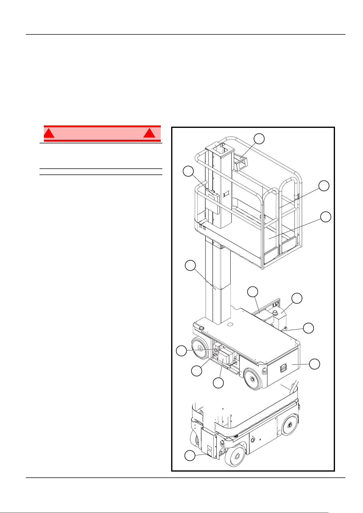
INTRODUCTION
This manual covers all models of the M1230E Aerial Work Platform. This manual must be stored on the
machine at all times.
Read, understand and follow all safety rules and operating instructions before attempting to operate the
machine.
GENERAL DESCRIPTION
Figure 1: M1230E Series
W A R N I N G
DO NOT use the maintenance
platform without guardrails properly
assembled and in place
1. Platform
2. Entry Gates
3. Elevating Mast
4. Platform Controls
5. Manual Case
6. Chassis Controls
7. Hydraulic Reservoir
8. Power / Control Module, Inc level
sensor (EZ230)
9. Battery Tray
10. Emergency Lowering Valve
11. Battery Charger
12. Drive Relief Valve
13. Charger Outlet Plug
4
5
2
1
3
6
7
8
13
9
12
11
10
Page 3 Operation Manual
Page 8

SPECIAL LIMITATIONS
Travel with the platform raised is limited to creep speed range.
Elevating the platform is limited to rm, level surfaces only.
Special Limitations
! !
D A N G E R
The elevating function shall ONLY be used when the work platform is level and on a rm surface.
The work platform is NOT intended to be driven over uneven, rough, or soft terrain.
PLATFORM CAPACITY
The maximum platform capacity for the M1230E is 227 kg (500 lbs). Two people may occupy the platform
indoors, while only one may occupy the platform outdoors.
! !
D A N G E R
DO NOT exceed the maximum platform capacity or the platform occupancy limits for this machine.
MANUAL FORCE
Manual force is the force applied by the occupants to objects such as walls or other structures outside the
work platform.
The maximum allowable manual force is limited to 200 N (45 lbs.) of force per occupant, with a maximum
of 400 N (90 lbs.) for two occupants.
! !
D A N G E R
DO NOT exceed the maximum amount of manual force for this machine.
BEAUFORT SCALE
Never operate the machine when wind speeds exceed 12.5m/s (28mph) [Beaufort scale 6].
BEAUFORT
RATING
3 3,4~5,4 12,25~19,4 11.5~17.75 7.5~12.0 Papers and thin branches move, ags wave.
4 5,4~8,0 19,4~28,8 17.75~26.25 12.0~18 Dust is raised, paper whirls up, and small branches sway.
5 8,0~10,8 28,8~38,9 26.25~35.5 18~24.25 Shrubs with leaves start swaying. Wave crests are apparent in ponds or swamps.
6 10,8~13,9 38,9~50,0 35.5~45.5 24.5~31 Tree branches move. Power lines whistle. It is difcult to open an umbrella.
7
m/s km/h ft/s mph
13,9~17,2 50,0~61,9 45.5~56.5 31.~38.5 Whole trees sway. It is difcult to walk against the wind.
WIND SPEED
GROUND CONDITIONS
Page 4Operation Manual
Page 9

Controls and Indicators
CONTROLS AND INDICATORS
The operator shall know the location of each control and indicator and have a thorough knowledge of the
function and operation of each before attempting to operate the unit.
Platform
Controller
3
Figure 2: Controls and Indicators
4
2
9
510428-001
5
Chassis Controller
7
1
8
0
510429-001
6
10
KEY
6. Toggle switch (chassis)
7. Enable button
8. Keyswitch
9. Horn Button
10. EZcal Display
ESC
ENTER
1. Joystick
2. Emergency Stop
3. Lift / Drive Select
4. Low Battery Indicator
5. Emergency Stop (chassis)
PRE-OPERATION SAFETY INSPECTION
NOTE: Carefully read, understand and follow all safety rules, operating instructions, labels and National
Safety Instructions/Requirements. Perform the following steps each day before use.
1. Open the Chassis Door and inspect for damage, uid leaks or missing parts.
2. Check the level of the hydraulic uid with the platform fully lowered. Open the Chassis Door and
remove the reservoir cap, uid should be visible on the dipstick. Add recommended hydraulic uid if
necessary. See “Specications” on page 14.
3. Check that the uid level in the batteries is correct. See “Battery Maintenance” on page 11.
4. Verify that the batteries are charged.
5. Check that the A.C. extension cord has been disconnected from the chassis outlet.
6. Check that all guardrails are in place and all fasteners are properly tightened.
7. Inspect the machine thoroughly for cracked welds and structural damage, loose or missing hardware,
hydraulic leaks, damaged control cable and loose wire connections.
Page 5 Operation Manual
Page 10

SYSTEM FUNCTION INSPECTION
!
!
Refer to Figure 1 and Figure 2 for the locations of various controls and indicators.
W A R N I N G
STAND CLEAR of the work platform while performing the following checks.
Before operating the machine, survey the work area for surface hazards such as holes, drop-offs,
bumps and debris.
Check in ALL directions, including above the work platform, for obstructions and electrical conductors.
Protect the control console cable from possible damage while performing checks.
1. Move the machine, if necessary, to an unobstructed area to allow for full elevation.
2. Turn the Chassis and Platform Emergency Stop Switches ON by twisting and pulling the buttons out.
3. Check Level Sensor operation:
a. Position the machine off of level by more than 2°.
b. Raise the Platform using the Chassis Controls.
System Function Inspection
• The alarm should sound, and the platform
should not lift more than 500mm.
4. Lower the platform by pushing the Chassis
Lift Switch to DOWN while holding the enable
switch on, and check the operation of the audible
lowering alarm.
5. Level the Machine.
6. Push the Chassis Lift Switch to the UP position
while holding the enable switch on and fully
elevate the platform.
7. Visually inspect the mast assembly for damage
or erratic operation. Check for missing or loose
parts.
8. Verify that the depression mechanism supports have rotated into position under the machine.
9. Check the Chassis Emergency Lowering Valve for proper operation (see Figure 4):
a. Open the valve by pulling the knob out.
b. Once the platform is fully lowered, close the valve by releasing the knob.
10. Push the Chassis Emergency Stop Switch down to the OFF position. All machine functions should be
disabled. Pull out the Chassis Emergency Stop Switch to resume.
11. Turn the Key Switch to Platform Control and Mount the platform.
12. Check that the route is clear of persons, obstructions, holes and drop-offs, is level and capable of
supporting the wheel loads.
13. After mounting platform, lower the bar across the entrance.
14. Select Drive mode.
15. While depressing the Joystick Interlock Switch, slowly position the Joystick to FORWARD then
REVERSE to check for speed and directional control. The farther you push or pull the Joystick from
center the faster the machine will travel.
16. Push the Steering Switch RIGHT then LEFT to check for steering control.
17. Push the Platform Emergency Stop Switch down to the OFF position. All machine functions should be
disabled. Pull out the Platform Emergency Stop Switch to resume.
Level Sensor
Figure 3: Level Sensor Location
Page 6Operation Manual
Page 11

Operation
OPERATION
TRAVEL WITH PLATFORM LOWERED
STEERING
Before operating the machine, ensure that the Pre-Operation Safety Inspection has been completed and
that any deciencies have been corrected. Never operate a damaged or malfunctioning machine. The
operator must be thoroughly trained on this machine.
1. Check that the route is clear of people, obstructions, holes and drop-offs, is level and is capable of
supporting wheel loads.
2. Verify that the Chassis Key Switch is turned to Platform Control and the Chassis Emergency Stop
Switch is ON, (pull button out).
3. After mounting the platform, Ensure Gates close behind you.
4. Check clearances above, below and to the sides of the machine.
5. Pull the Controller Emergency Stop switch up to the ON position.
6. Select DRIVE mode.
7. While depressing the Joystick Interlock Switch, slowly push or pull the Joystick to FORWARD or
REVERSE position to travel in the desired direction. The farther you push or pull the Joystick from
center the faster the machine will travel.
NOTE: Steering is not self-centering. Wheels must be returned to straight ahead position by
operating the Steering Switch.
1. Select DRIVE mode.
2. While depressing the Interlock Switch, push the Steering Switch to RIGHT or LEFT to turn the wheels
in the desired direction. Observe the tires while maneuvering the machine to ensure proper direction.
ELEVATING PLATFORM
1. Select LIFT mode.
2. While depressing the Joystick Interlock Switch, push Joystick forward to UP, the farther you push the
Joystick the faster the Platform will elevate.
3. If the machine is not level the Tilt Alarm will sound and the machine will not lift or drive. If the Tilt alarm
sounds the platform must be lowered and the machine moved to a level location before attempting to
re-elevate the Platform.
TRAVEL WITH PLATFORM ELEVATED
NOTE: The machine will travel at reduced speed when the platform is elevated.
1. Check that the route is clear of persons, obstructions, holes and drop-offs, is level and capable of
supporting the wheel loads.
2. Check clearances above, below and to the sides of the platform.
3. With the Machine elevated above 500mm Select DRIVE mode.
4. While depressing the Joystick Interlock Switch, push Joystick to FORWARD or REVERSE for desired
direction of travel.
5. If the machine is not level the Tilt Alarm will sound and the machine will not lift or drive. If the Tilt alarm
sounds the platform must be lowered and the machine moved to a level location before attempting to
re-elevate the Platform.
LOWERING PLATFORM
1. Select LIFT mode.
2. While depressing the Joystick Interlock Switch, pull back on the Joystick.
Page 7 Operation Manual
Page 12

EMERGENCY LOWERING
Operation
!
If the platform should fail to lower, NEVER climb down the elevating assembly.
Stand clear of the elevating assembly while operating the Emergency Lowering Valve Knob.
Ask a person on the ground to open the Emergency Lowering Valve
to lower the platform. The Emergency Lowering Valve is located at
the front of the chassis.
1. Open the Emergency Lowering Valve by pulling the knob out.
2. To close, release the knob.
NOTE: The platform will not elevate if the Emergency Lowering
W A R N I N G
Valve is open.
!
Figure 4: Emergency Lowering Valve
Emergency
Lowering Valve
PARKING BRAKE RELEASE
Perform the following procedure only when the machine will not operate under its own power and it is
necessary to move the machine, or when winching onto a trailer to transport.
Figure 5: Parking Brake Release
1. Remove the spring compression nut so the spring is loose and the
brake bars are away from the tires.
2. Disconnect the Drive Motor Hydraulic Hose from port “D1” on the
Hydraulic Manifold and immediatelly cap the opening to prevent
foreign material from entering, open the cap from the Oil Tank and
place the end of the hose into the Tank. This will allow the Drive
Motors to turn freely and oil from them will be fed back into the
Tank.
3. The machine will now roll when pushed or pulled.
Spring
Compression
Nut
After moving the machine and before normal operation:
1. Reconnect the Drive Motor hose to “D1” on the Hydraulic
Manifold.
2. Ensure Drive / Steer wheels are clear of the ground.
3. Operate drive (fwd or rev), Assistance will be required to complete this process.
4. Adjust Spring compression nut until spring fully compressed.
5. Restore machine to its original position.
!
Never tow faster than 0,3 m/sec. (1 ft./sec.). Never operate the machine with the parking brakes
released. Serious injury or damage could result.
W A R N I N G
!
AFTER USE EACH DAY
1. Ensure that the platform is fully lowered.
2. Park the machine on a rm level surface, preferably under cover, secure against vandals, children and
unauthorized operation.
3. Turn the Chassis Key Switch to OFF and remove the key to prevent unauthorized operation.
Page 8Operation Manual
Page 13

Transporting the Machine
TRANSPORTING THE MACHINE
BY CRANE
Secure the straps to chassis lifting/tie down points only.
BY FORKLIFT
! !
D A N G E R
Forklifting is for transport only.
See specications for weight of machine and be certain that forklift is of adequate capacity to lift the
machine.
Figure 6: Transporting the Machine
Forklift from the side by lifting under the Chassis.
BY TRUCK
1. Maneuver the machine into transport position and
chock wheels.
2. Secure the machine to the transport vehicle
with chains or straps of adequate load capacity
attached to the chassis lifting/tie down points.
C A U T I O N
Overtightening of the chains or straps attached to the
Tie Down lugs may result in damage to the machine
Forklift From
Side
Typical Tie Down/Lift Points
(D-Rings)
CENTRE OF GRAVITY WHEN EMPTY
Wheel Load Decal
Centre of GravityCentre of Gravity
600mm
Page 9 Operation Manual
Page 14

MAINTENANCE
Maintenance
!
W A R N I N G
!
Never perform service while the platform is elevated without rst blocking the elevating assembly. DO
NOT stand in the elevating assembly area while deploying or storing the brace.
Figure 7: Supporting the Elevating Assembly
BLOCKING THE ELEVATING ASSEMBLY
INSTALLATION
1. Park the machine on rm level ground.
2. Verify that both Emergency Stop Switches are ON.
3. Turn and hold the Chassis Key Switch to CHASSIS.
4. Position the Chassis Lift Switch to UP and elevate the platform
approximately 1,2 m (4 ft.).
5. Place a solid wood block, 51mm x 100mm x 45cm (2”x 4”x18”)
between the second mast section and Chassis just behind the
mast assembly.
6. Push the Chassis Lift Switch to the DOWN position and
gradually lower the platform until the second mast section is
supported by the block.
Number 2 Mast
Wood Block
REMOVAL
1. Push the Chassis Lift Switch to the UP position and gradually raise platform until the wood block can
be removed.
2. Remove the block.
3. Push the Chassis Lift Switch to the DOWN position and completely lower the platform.
HYDRAULIC FLUID
The hydraulic uid reservoir is located in the chassis door.
Figure 8: Hydraulic Fluid Reservoir and Dipstick
NOTE: Never add uid if the platform is elevated.
CHECK HYDRAULIC FLUID
1. Make sure that the platform is fully lowered.
2. Open the chassis door.
3. Check the uid level using the guage on the tank..
4. To add Hydraulic uid remove Filler Cap in Fig 8.
5. Add the appropriate uid to bring the level to the
FULL mark. See “Specications” on page 14
Filler Cap and
Level guage
Page 10Operation Manual
Page 15
Maintenance
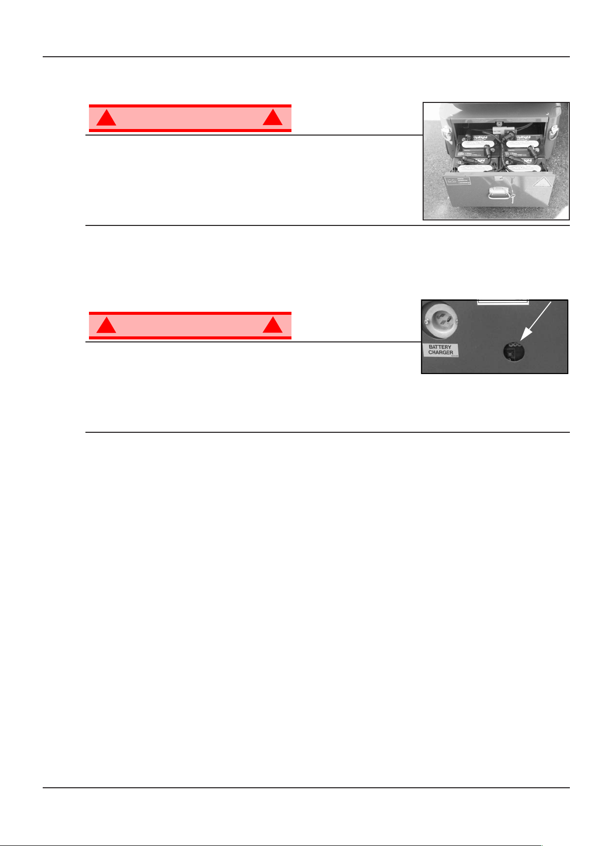
BATTERY MAINTENANCE
Figure 9: Access to Batteries
!
Hazard of explosive gas mixture. Keep sparks, ame, and smoking
material away from batteries.
Always wear safety glasses when working near batteries.
Battery uid is highly corrosive. Thoroughly rinse away any spilled uid
with clean water.
Always replace batteries with SNORKEL batteries or manufacturer
approved replacements weighing 26,3 kg (58 lbs.) each.
BATTERY CHARGING
!
Charge the batteries in a well ventilated area. Do not charge the
batteries when the machine is near a source of sparks or ames.
Permanent damage to the batteries will result if the batteries are not
immediately recharged after discharging.
Never leave the battery charger operating for more than two days.
Never disconnect the cables from the batteries when the charger is operating.
Keep the charger dry.
W A R N I N G
• Check the battery uid level daily, especially if the machine is being used in a warm, dry climate.
• Keep the terminals and tops of the batteries clean.
• Refer to the Service Manual to extend battery life and for complete service instructions.
W A R N I N G
!
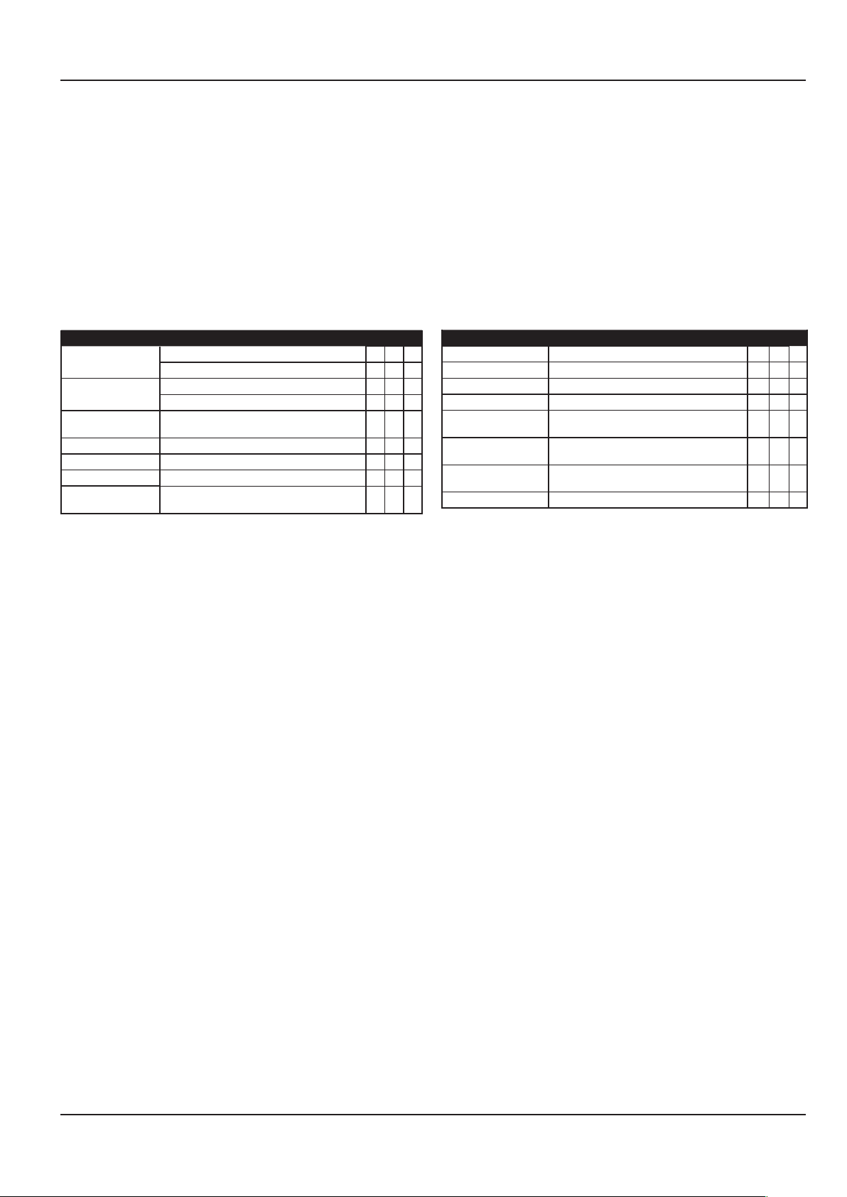
Figure 10: Battery Charge Indicator
!
1. Check the battery uid level. If the battery uid level is lower than 10 mm (3/8 in.) above the plates add
distilled water only.
2. Connect an extension cord (1,5 mm² [12 gauge] minimum conductor diameter; 15 m (50 ft.) maximum
length) to the charger plug located at the left side of the chassis.
3. The charger turns on automatically after a short delay. Look through the charge indicator cutout to
check the state of charge.
• 0 - 50% charge:
• First Light -BLINKING-
• Second and Third Light -OFF
• 50% - 75% Charge:
• First Light -ON
• Second Light -BLINKING-
• Third Light -OFF
• 75% - 100% Charge:
• First and Second Light -ON
• Third Light - BLINKING-
• Charge Complete
• All Lights -ON
• The charger automatically shuts down to low current after charging is complete and all lights turn ON.
• The charger continues at low current (equalizing charge) for 3-4 hours, then charging current shuts
off completely.
4. Lights remain ON until the AC power supply is disconnected.
NOTE: The battery charger circuit must be used with a GFI (Ground Fault Interrupt) outlet.
NOTE: DO NOT operate the machine while the charger is plugged in.
Page 11 Operation Manual
Page 16

INSPECTION AND MAINTENANCE SCHEDULE
The Complete Inspection consists of periodic visual and operational checks, along with periodic minor
adjustments that assure proper performance. Daily inspection will prevent abnormal wear and prolong
the life of all systems. The inspection and maintenance schedule should be performed at the specied
intervals or at intervals to suit the relevant national body whichever is the lesser. Inspection and
maintenance shall be performed by personnel who are trained and familiar with mechanical and electrical
procedures.
Inspection and Maintenance Schedule
W A R N I N G
!
Before performing preventative maintenance, familiarize yourself with the operation of the machine.
Always block the elevating assembly whenever it is necessary to perform maintenance while the
platform is elevated.
The daily preventative maintenance checklist has been designed for machine service and maintenance.
Please photocopy the Daily Preventative Maintenance Checklist and use the checklist when inspecting
the machine.
!
Page 12Operation Manual
Page 17
Daily Preventative Maintenance Checklist
DAILY PREVENTATIVE MAINTENANCE CHECKLIST
MAINTENANCE TABLE KEY
Y = Yes/Acceptable
N = No/Not Acceptable
R = Repaired/Acceptable
COMPONENT INSPECTION OR SERVICES Y N R
Battery
Chassis
Control Cable
Controller Check switch operation.
Drive Motors Check for operation and leaks.
Elevating Assembly Inspect for structural cracks.
Emergency
Hydraulic System
Check electrolyte level.
Check battery cable condition.
Check hoses for pinch or rubbing points.
Check welds for cracks.
Check the exterior of the cable for pinching,
binding or wear.
Operate the emergency lowering valve and
check for serviceability.
PREVENTATIVE MAINTENANCE REPORT
Date: ________________________________________
Owner: ______________________________________
Model No: ____________________________________
Serial No: _____________________________________
Serviced By: __________________________________
COMPONENT INSPECTION OR SERVICES Y N R
Entire Unit Check for and repair collision damage.
Hydraulic Fluid Check uid level.
Hydraulic Pump Check for hose tting leaks.
Hydraulic System Check for leaks.
Labels
Platform Deck and
Rails
Platform Deck and
Rails
Tires Check for damage.
Check for peeling, missing, or unreadable
labels & replace.
Check welds for cracks.
Check condition of deck.
Page 13 Operation Manual
Page 18

SPECIFICATIONS
ITEM M1230E
Maximum Platform Capacity 227 kg (500 lbs.)
Maximum Number of Occupants 2 People indoors/1 person outdoors
Working Height 5,6 m (18 ft.)
Maximum Platform Height 3,63 m (11 ft. 11 in.)
Minimum Platform Height 48,3 cm (19 in.)
Weight 780 kg (1720 lbs.)
Overall Width 76 cm (30 in.)
Overall Height 165 cm (65 in.)
Overall Length 1,36 m (53.5 in.)
Platform Lowered 3,2 km/h (1.99 mph)
Platform Raised 0,65 km/h (0.46 mph)
Hydraulic Reservoir Capacity 7,2 L (1.9 gal)
Maximum Hydraulic System Pressure 165 bar (2400 psi)
Normal above 32° F [0° C] ISO #46
Low Temp. below 32° F [0° C] ISO #32
below 0° F [-17° C] ISO #15
Maximum Gradeability 14º (25%)
Max Chassis Inclination 1.5° Side to Side
Vibration of this machine does not exceed 2.5m/sec
Sound Pressure Level 68dB (A) at Control Station
Operating Temperature Range -20° C to +50° C
Specications
Platform Size 74cm x 96cm (29 in. x 38 in.)
Height
Dimensions
Drive Speed
Energy Source 24V battery pack
Four 220 ampere hour, 6 Volt batteries, min. wt. 26,3 kg (58 lbs.) each
4 HP DC electric motor
System Voltage 24 VDC
Battery Charger 20 AMP, 220 V AC 50Hz
Battery Duty Cycle 25% for 8 Hours
Hydraulic Fluid
Lift System One Single Stage Lift Cylinder
Drive Control Proportional
Control System Proportional Control Handle with Interlock, Selector Switch, Red
Mushroom Emergency Stop Switches
Horizontal Drive Dual Front Wheel
Tires 30,5 cm (12 in.) diameter solid rubber, Non-marking
Parking Brakes Dual, Spring Applied, Hydraulic Release
Turning Radius 37 cm (14.5 in.) Inside
Wheel Base 97,8 cm (38.5 in.)
Guardrails 1,10 m (43 in.)
Toeboard 152 mm (6 in.)
2.0° Front to Back
Wheel loading 325kg per wheel / 716.5 lbs per wheel
2
*Specications are subject to change without notice. Hot weather or heavy use may affect performance.
Refer to the Service Manual for complete parts and service information.
This machine meets or exceeds all applicable CE and GS machinery directive requirements.
Page 14Operation Manual
Page 19

Page 20

Local Distributor / Lokaler Vertiebshändler / Distributeur local
El Distribuidor local / ll Distributore locale
EUROPE, MIDDLE EAST
AFRICA & ASIA
PHONE: +44 (0) 845 1550 057
FAX: +44 (0) 845 1557 756
NORTH & SOUTH AMERICA
PHONE: +1 785 989 3000
TOLL FREE: +1 800 225 0317
FAX: +1 785 989 3070
AUSTRALIA
PHONE: +61 2 9725 4000
FAX: +61 2 9609 3057
NEW ZEALAND
PHONE: +64 6 3689 168
FAX: +64 6 3689 164
 Loading...