

Page 1

Operator Manual
Guide de l’opérateur
Betriebsanleitung
LX Series
SERIAL NO. 4275 to Current
WARNING
All personnel shall carefully read, understand and follow all safety rules,
operating instructions, and National Safety Instructions/Requirements
before operating or performing maintenance on any UpRight Aerial Work
Platform.
The first section of this Operator Manual is the English language version.
AVERTISSEMENT
Tout le personnel doit lire attentivement, bien comprendre et suivre toutes
les règles de sécurité, le mode d’emploi et les règles nationales de sécurité avant d’entretenir ou d’utiliser une plate-forme élévatrice UpRight.
La deuxième section du guide de l’opérateur est la version française.
WARNUNG
Alle Bediener müssen die Sicherheitsregeln, Betriebsanleitungen sowie
geltenden Sicherheitsanweisungen/-anforderungen gründlich durchlesen,
verstehen und befolgen, bevor sie an irgendeiner UpRight-Hocharbeitsbühne Wartungsarbeiten ausführen oder diese in Betrieb nehmen.
Der dritte Abschnitt dieser Betriebsanleitung ist deutschsprachig.
P/N 067903-025
Page 2
LX Series
Serial Numbers 4275 – Current
NGLISH
E
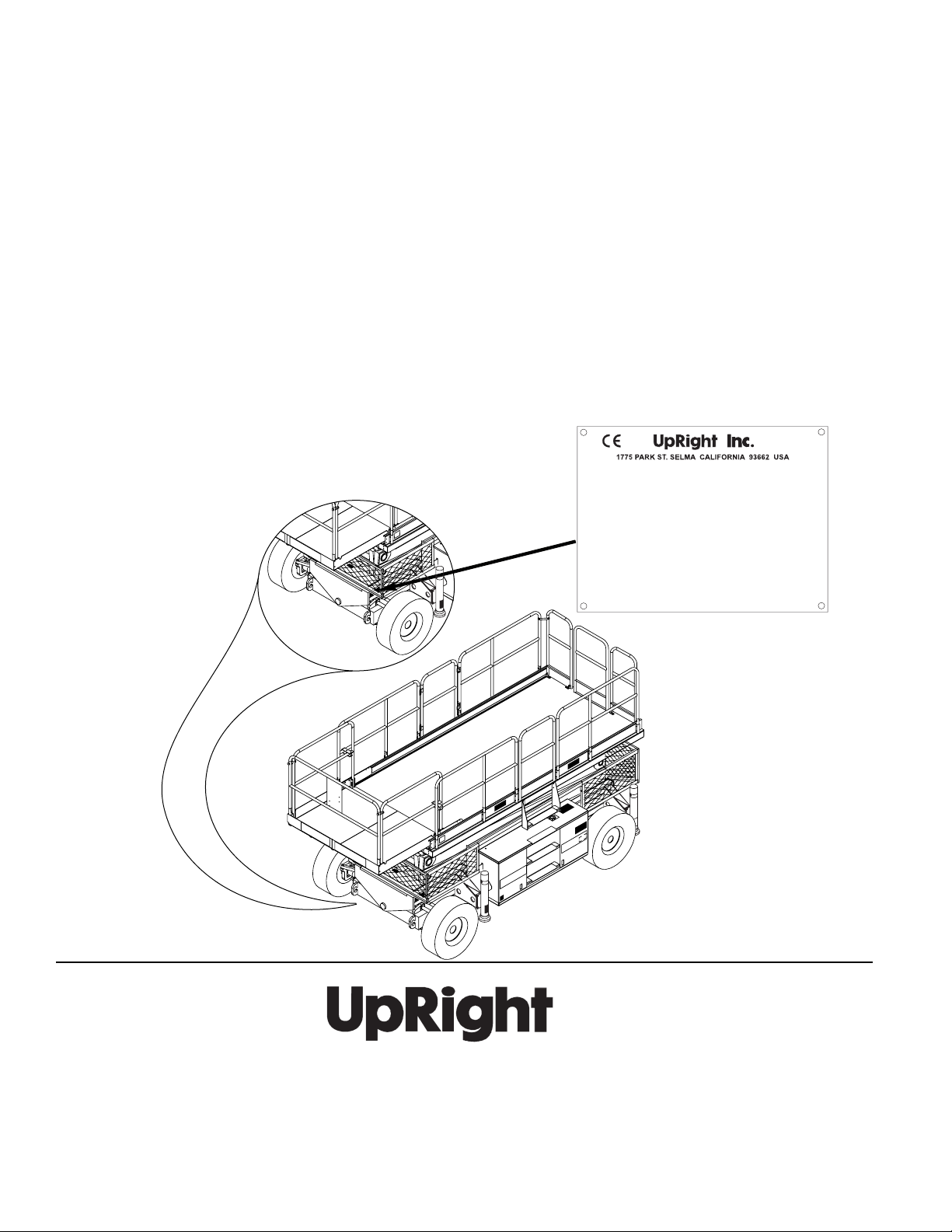
When contacting UpRight for service or parts information, be sure to include the MODEL and SERIAL NUMBERS from the
equipment nameplate. Should the nameplate be missing, the SERIAL NUMBER is also stamped on top of the chassis
above the front axle pivot.
RANÇAIS
F
Lors des communications avec UpRight pour des informations au sujet de l’entretient ou des pièces, ne pas oublier
d’inclure les NUMÉROS DE MODÈLE et de SÉRIE inscrits sur la plaque signalétique. Si la plaque signalétique manque, le
NUMÉRO DE SÉRIE est également estampé sur le dessus du châssis, au-dessus de l’axe pivot avant.
EUTSCH
D
Stellen Sie sicher, dass Sie die MODELL- und SERIENNUMMERN auf dem Gerätetypenschild angeben, wenn Sie sich mit
UpRight bezüglich Wartungs- oder Ersatzteilinformationen in Verbindung setzten. Sollte das Typenschild fehlen, finden Sie
die SERIENNUMMER auch auf dem Fahrwerk über der vorderen Schwenkachse.
Model______________ Serial number:____ _______
Machine weight _______kg Mfg. date:_________
Maximum wheel load:________
Maximum allowable incline of machine when elevated:_ ____deg.
Occupants and equipment must not exceed the rated maximum
load:_____kg Maximum platform occupa nts: _ ____
Maximum allowable sIde force on platform:_____N
Maximum platform height:______m
Maximum platform reach:______m
Maximum allowable wind speed: ______m/s=Beaufor t scale_____
Maximum hydraulic system pressure:___ __bar
Maximum system voltag e: _______Vdc
This machine is manufactured to co mply with
Machinery directive 89-392/CEE
CAUTION: CONSULT OPERAT OR'S MANUAL BEFORE USE.
061205-003
UpRight, Inc.
801 South Pine Street
Madera, California 93637
TEL: 559-662-3900
FAX: 559-673-6184
PARTS: 1-888-UR-PARTS
PARTS FAX: 1-800-669-9884
Call Toll Free in U.S.A.
1-800-926-LIFT
UpRight
Unit S1, Park West Industrial Park
Friel Avenue
Nangor Road
Dublin 12, Ireland
TEL: +353 1 620 9300
FAX: +353 1 620 9301
Page 3
PERATOR
O
M
ANUAL
WARNING
All personnel shall carefully read, understand and follow all safety rules and operating
instructions before operating or performing maintenance on any UpRight aerial work platform.
Safety Rules
Safety Rules
Safety RulesSafety Rules
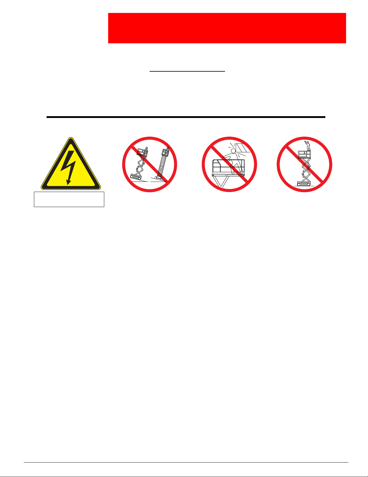
Electrocution Hazard
Electrocution Hazard Tip Over Hazard
Electrocution HazardElectrocution Hazard
THIS MACHINE IS NOT
INSULATED!
NEVER
the machine while elevated unless the
Tip Over Hazard Collision Hazard
Tip Over HazardTip Over Hazard
elevate the platform or drive
machine is on a firm, level surface.
Collision Hazard Fall Hazard
Collision HazardCollision Hazard
NEVER
without first checking for overhead
obstructions or other hazards.
position the platform
Fall Hazard
Fall HazardFall Hazard
climb, stand or sit on
NEVER
platform guardrails or midrail.
USE OF THE AERIAL WORK PLATFORM
used for the job. It is designed for repair and assembly jobs and assignments at overhead workplaces (ceilings, cranes, roof structures,
buildings etc.). All other uses of the aerial work platform are prohibited!
THIS AERIAL WORK PLATFORM IS NOT INSULATED!
trical equipment!
Exceeding the specified permissible maximum load
The use and operation of the aerial work platform as a lifting tool or a crane (lifting of loads from below upwards or from up high on
down)
is prohibited!
NEVER
DISTRIBUTE
NEVER
and avoiding them.
OPERATE
NEVER
IN CASE OF EMERGENCY
IF ALARM SOUNDS
Climbing up the railing of the platform, standing on or stepping from the platform onto buildings, steel or prefab concrete structures, etc.,
is prohibited!
Dismantling the swing gate or other railing components
locked!
It is prohibited
To extend the height or the range by placing of ladders, scaffolds or similar devices on the platform
NEVER
INSPECT
cables or hoses before using.
VERIFY
NEVER
To bypass any safety equipment
range.
NEVER
Modifications to the aerial work platform
AFTER USE
exceed the manual force allowed for this machine. See “Special Limitations” on page 4 for details.
all platform loads evenly on the platform.
operate the machine without first surveying the work area for surface hazards such as holes, drop-offs, bumps, curbs, or debris;
machine only on surfaces capable of supporting wheel loads.
operate the machine when wind speeds exceed this machine’s wind rating. See “Beaufort Scale” on page 4 for details.
push EMERGENCY STOP switch to deactivate all powered functions.
while platform is elevated, STOP, carefully lower platform. Move machine to a firm, level surface.
to keep the swing gate in an open position (held open with tie-straps) when the platform is raised!
perform service on machine while platform is elevated without blocking elevating assembly.
the machine thoroughly for cracked welds, loose or missing hardware, hydraulic leaks, loose wire connections, and damaged
that all labels are in place and legible before using.
use a machine that is damaged, not functioning properly, or has damaged or missing labels.
is prohibited
charge batteries near sparks or open flame. Charging batteries emit explosive hydrogen gas.
, secure the work platform from unauthorized use by turning both keyswitches off and removing key.
: This aerial work platform is intended to lift persons and his tools as well as the material
For this reason it is imperative to keep a safe distance from live parts of elec-
is prohibited!
is prohibited!
and presents a danger for the persons on the aerial work platform and in its working
are prohibited
or permissible only at the approval by UpRight.
See “Special Limitations” on page 4 for details.
Always make certain that the swing gate is closed and securely
is prohibited!
Page 1
Page 4

067903-025 LX31/LX41/LX50
C
ONTENTS
Introduction. . . . . . . . . . . . . . . . . . . . . . . . . . . . . . . . . . . . . . . . . . . . . . . . . . . . . . . . . . . . . . . . . . . . . . . . . .3
General Description . . . . . . . . . . . . . . . . . . . . . . . . . . . . . . . . . . . . . . . . . . . . . . . . . . . . . . . . . . . . . . . . . . .3
Special Limitations . . . . . . . . . . . . . . . . . . . . . . . . . . . . . . . . . . . . . . . . . . . . . . . . . . . . . . . . . . . . . . . . . . . .4
All Models:. . . . . . . . . . . . . . . . . . . . . . . . . . . . . . . . . . . . . . . . . . . . . . . . . . . . . . . . . . . . . . . . . . . . . . . . . . . . . . . . . 4
Platform Capacity . . . . . . . . . . . . . . . . . . . . . . . . . . . . . . . . . . . . . . . . . . . . . . . . . . . . . . . . . . . . . . . . . . . . . . . . . . . 4
Manual Force . . . . . . . . . . . . . . . . . . . . . . . . . . . . . . . . . . . . . . . . . . . . . . . . . . . . . . . . . . . . . . . . . . . . . . . . . . . . . . 4
Beaufort Scale. . . . . . . . . . . . . . . . . . . . . . . . . . . . . . . . . . . . . . . . . . . . . . . . . . . . . . . . . . . . . . . . . . . . . . . . . . . . . . 4
Lift Overload Alarm . . . . . . . . . . . . . . . . . . . . . . . . . . . . . . . . . . . . . . . . . . . . . . . . . . . . . . . . . . . . . . . . . . . . . . . . . . 4
Controls and Indicators . . . . . . . . . . . . . . . . . . . . . . . . . . . . . . . . . . . . . . . . . . . . . . . . . . . . . . . . . . . . . . . .5
Pre-Operation & Safety Inspection . . . . . . . . . . . . . . . . . . . . . . . . . . . . . . . . . . . . . . . . . . . . . . . . . . . . . . .6
System Function Inspection . . . . . . . . . . . . . . . . . . . . . . . . . . . . . . . . . . . . . . . . . . . . . . . . . . . . . . . . . . . .6
Operation. . . . . . . . . . . . . . . . . . . . . . . . . . . . . . . . . . . . . . . . . . . . . . . . . . . . . . . . . . . . . . . . . . . . . . . . . . . .8
Travel with Platform Lowered . . . . . . . . . . . . . . . . . . . . . . . . . . . . . . . . . . . . . . . . . . . . . . . . . . . . . . . . . . . . . . . . . . 8
Travel with Work Platform Elevated . . . . . . . . . . . . . . . . . . . . . . . . . . . . . . . . . . . . . . . . . . . . . . . . . . . . . . . . . . . . . 9
Steering. . . . . . . . . . . . . . . . . . . . . . . . . . . . . . . . . . . . . . . . . . . . . . . . . . . . . . . . . . . . . . . . . . . . . . . . . . . . . . . . . . . 9
Raising and Lowering the Platform . . . . . . . . . . . . . . . . . . . . . . . . . . . . . . . . . . . . . . . . . . . . . . . . . . . . . . . . . . . . . . 9
Leveling the Platform
(Outrigger equipped machines only) . . . . . . . . . . . . . . . . . . . . . . . . . . . . . . . . . . . . . . . . . . . . . . . . . . . . . . . . . . . . 10
Outrigger Switches and Indicator Lights . . . . . . . . . . . . . . . . . . . . . . . . . . . . . . . . . . . . . . . . . . . . . . . . . . . . . 10
To Level the Platform (Extend the Outriggers). . . . . . . . . . . . . . . . . . . . . . . . . . . . . . . . . . . . . . . . . . . . . . . . . 10
To Retract the Outriggers. . . . . . . . . . . . . . . . . . . . . . . . . . . . . . . . . . . . . . . . . . . . . . . . . . . . . . . . . . . . . . . . . 10
Emergency Lowering. . . . . . . . . . . . . . . . . . . . . . . . . . . . . . . . . . . . . . . . . . . . . . . . . . . . . . . . . . . . . . . . . . . . . . . . 11
LX31 and LX41 . . . . . . . . . . . . . . . . . . . . . . . . . . . . . . . . . . . . . . . . . . . . . . . . . . . . . . . . . . . . . . . . . . . . . . . . 11
LX50. . . . . . . . . . . . . . . . . . . . . . . . . . . . . . . . . . . . . . . . . . . . . . . . . . . . . . . . . . . . . . . . . . . . . . . . . . . . . . . . . 11
Towing or Winching . . . . . . . . . . . . . . . . . . . . . . . . . . . . . . . . . . . . . . . . . . . . . . . . . . . . . . . . . . . . . . . . . .12
Parking Brake Release . . . . . . . . . . . . . . . . . . . . . . . . . . . . . . . . . . . . . . . . . . . . . . . . . . . . . . . . . . . . . . . . . . . . . . 12
After Use Each Day. . . . . . . . . . . . . . . . . . . . . . . . . . . . . . . . . . . . . . . . . . . . . . . . . . . . . . . . . . . . . . . . . . .12
Fold Down Guardrails . . . . . . . . . . . . . . . . . . . . . . . . . . . . . . . . . . . . . . . . . . . . . . . . . . . . . . . . . . . . . . . .13
Fold Down Procedure . . . . . . . . . . . . . . . . . . . . . . . . . . . . . . . . . . . . . . . . . . . . . . . . . . . . . . . . . . . . . . . . . . . . . . . 13
Erection Procedure . . . . . . . . . . . . . . . . . . . . . . . . . . . . . . . . . . . . . . . . . . . . . . . . . . . . . . . . . . . . . . . . . . . . . . . . . 13
Transporting the Work Platform . . . . . . . . . . . . . . . . . . . . . . . . . . . . . . . . . . . . . . . . . . . . . . . . . . . . . . . .14
Preparation for Shipment . . . . . . . . . . . . . . . . . . . . . . . . . . . . . . . . . . . . . . . . . . . . . . . . . . . . . . . . . . . . . . . . . . . . 14
Lifting By Crane. . . . . . . . . . . . . . . . . . . . . . . . . . . . . . . . . . . . . . . . . . . . . . . . . . . . . . . . . . . . . . . . . . . . . . . . . . . . 14
Driving or Winching onto a Truck or Trailer. . . . . . . . . . . . . . . . . . . . . . . . . . . . . . . . . . . . . . . . . . . . . . . . . . . . . . . 14
Maintenance . . . . . . . . . . . . . . . . . . . . . . . . . . . . . . . . . . . . . . . . . . . . . . . . . . . . . . . . . . . . . . . . . . . . . . . .15
Blocking the Elevating Assembly . . . . . . . . . . . . . . . . . . . . . . . . . . . . . . . . . . . . . . . . . . . . . . . . . . . . . . . . . . . . . . 15
Brace Installation . . . . . . . . . . . . . . . . . . . . . . . . . . . . . . . . . . . . . . . . . . . . . . . . . . . . . . . . . . . . . . . . . . . . . . . 15
Brace Removal. . . . . . . . . . . . . . . . . . . . . . . . . . . . . . . . . . . . . . . . . . . . . . . . . . . . . . . . . . . . . . . . . . . . . . . . . 15
Hydraulic Fluid. . . . . . . . . . . . . . . . . . . . . . . . . . . . . . . . . . . . . . . . . . . . . . . . . . . . . . . . . . . . . . . . . . . . . . . . . . . . . 15
Battery Maintenance . . . . . . . . . . . . . . . . . . . . . . . . . . . . . . . . . . . . . . . . . . . . . . . . . . . . . . . . . . . . . . . . . . . . . . . . 16
Engine . . . . . . . . . . . . . . . . . . . . . . . . . . . . . . . . . . . . . . . . . . . . . . . . . . . . . . . . . . . . . . . . . . . . . . . . . . . . . . . . . . . 17
Coolant. . . . . . . . . . . . . . . . . . . . . . . . . . . . . . . . . . . . . . . . . . . . . . . . . . . . . . . . . . . . . . . . . . . . . . . . . . . . . . . 17
Oil. . . . . . . . . . . . . . . . . . . . . . . . . . . . . . . . . . . . . . . . . . . . . . . . . . . . . . . . . . . . . . . . . . . . . . . . . . . . . . . . . . . 17
Fuel . . . . . . . . . . . . . . . . . . . . . . . . . . . . . . . . . . . . . . . . . . . . . . . . . . . . . . . . . . . . . . . . . . . . . . . . . . . . . . . . . 17
Preventative Maintenance Schedule. . . . . . . . . . . . . . . . . . . . . . . . . . . . . . . . . . . . . . . . . . . . . . . . . . . . .18
Daily Preventative Maintenance Check List . . . . . . . . . . . . . . . . . . . . . . . . . . . . . . . . . . . . . . . . . . . . . . . . . . . . . . 18
Maintenance Table Key . . . . . . . . . . . . . . . . . . . . . . . . . . . . . . . . . . . . . . . . . . . . . . . . . . . . . . . . . . . . . . . . . . 18
Maintenance Report. . . . . . . . . . . . . . . . . . . . . . . . . . . . . . . . . . . . . . . . . . . . . . . . . . . . . . . . . . . . . . . . . . . . . 18
Labels . . . . . . . . . . . . . . . . . . . . . . . . . . . . . . . . . . . . . . . . . . . . . . . . . . . . . . . . . . . . . . . . . . . . . . . . . . . . .20
Specifications . . . . . . . . . . . . . . . . . . . . . . . . . . . . . . . . . . . . . . . . . . . . . . . . . . . . . . . . . . . . . . . . . . . . . . .22
Page 2 Operator Manual
Page 5
Introduction 067903-025 LX31/LX41/LX50
WARNING
!
!
I
NTRODUCTION
G
ENERAL
This manual covers the operation of the LX 31, LX 41 and LX50 Internal Combustion Work Platform.
amnual must be stored on the machine at all times.
D
ESCRIPTION
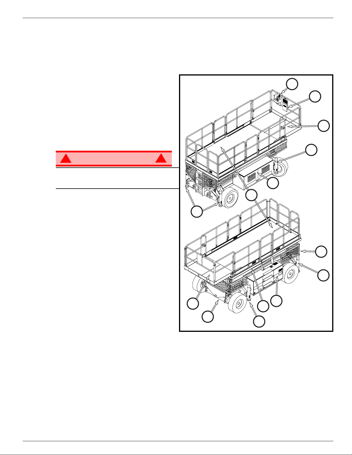
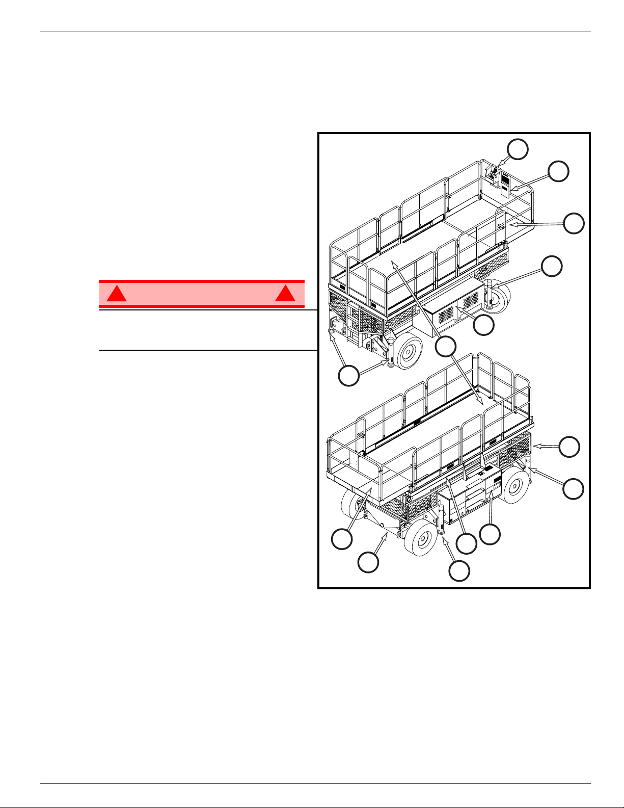
Figure 1:
1. Platform
LX Series Work Platform
3
The platform has a reinforced steel floor,
guardrails with midrail, toeboards and an
entrance gate at the rear and both sides of
the platform. The guardrails can be folded
down for access through doors or for shipment.
2. Slide-out Deck
10
DO NOT use the maintenance platform
without guardrails properly assembled and in
place
3. Platform Controls
1
8
This
4
2
The platform controls contain the controls to
operate the machine. It should be hung on
the front, left, or right guardrail.
4. Manual Case
5. Elevating Assembly
The platform is raised and lowered by the
elevating assembly; a five section scissor
assembly powered by two single-stage lift
cylinders.
6. Scissor Guard
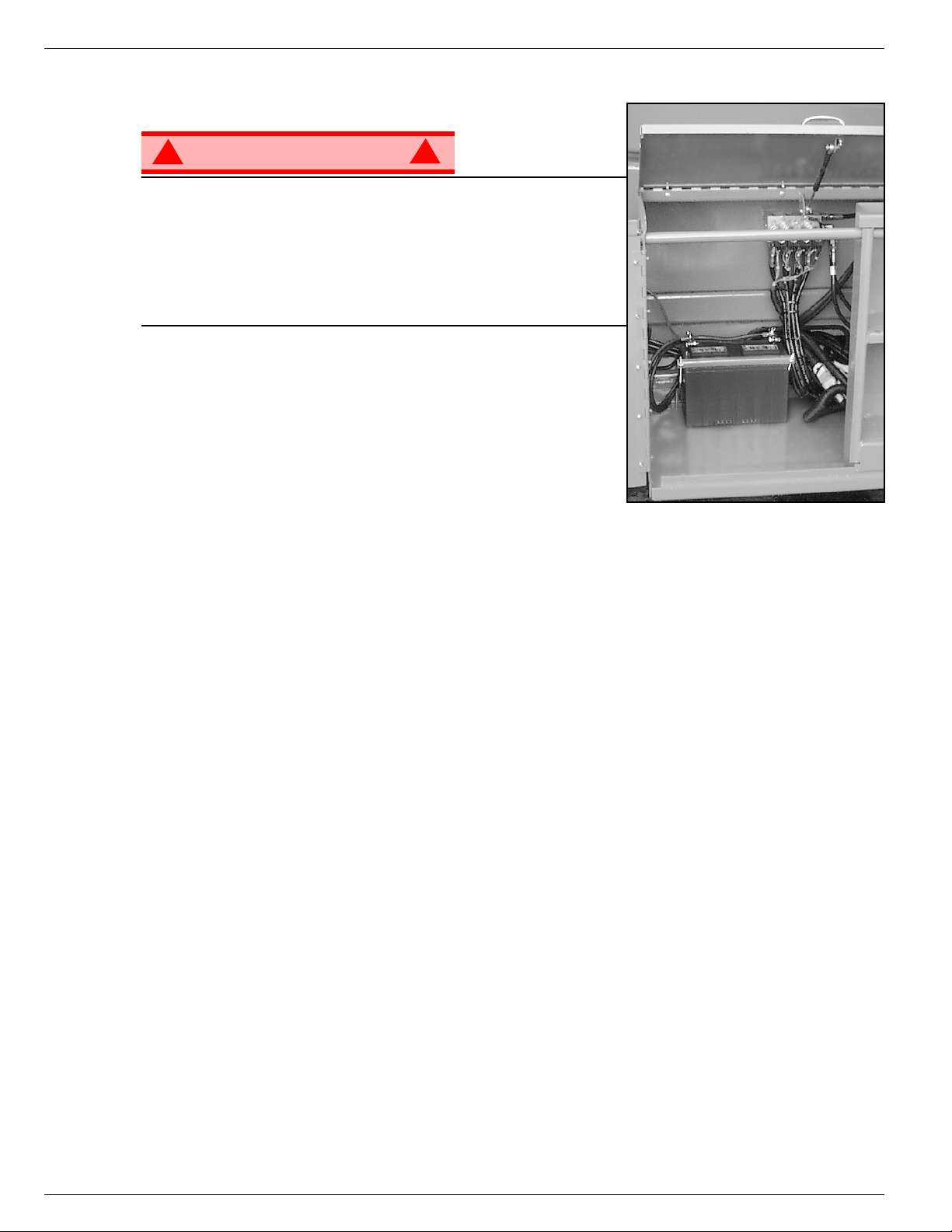
7. Control Module
The control module contains the fuel tank,
hydraulic valve manifold, horn/alarms, battery, and chassis control panel.
8. Power Module
The power module contains the engine, the hydraulic pump, the hydraulic reservoir.
9. Chassis
The chassis is a structural frame that supports all the components of the Work Platform.
10. Outriggers (optional)
10
2
7
5
9
10
6
10
Operator Manual Page 3
Page 6
067903-025 LX31/LX41/LX50 Special Limitations
DANGER
! !
DANGER
! !
DANGER
! !
DANGER
! !
S
PECIAL
L
IMITATIONS
A
LL
M
ODELS
Travel with the platform raised is limited to a creep speed range.
Elevating of the Work Platform is limited to firm, level surfaces only.
The elevating function shall ONLY be used when the work platform is level and on a firm surface.
The work platform is NOT intended to be driven over uneven, rough, or soft terrain.
P
LATFORM
The maximum capacity for the MACHINE, including occupants is determined by model and options, and
is listed in “Specifications” on page 22.
DO NOT exceed the maximum platform capacity or the platform occupancy limits for this machine.
:
C
APACITY
M
ANUAL
Manual force is the force applied by the occupants to objects such as walls or other structures outside the
work platform.
The maximum allowable manual force is limited to 200 N (45 lbs.) of force per occupant, with a maximum
of 400 N (90 lbs.) for two or more occupants.
DO NOT exceed the maximum amount of manual force for this machine.
B
EAUFORT
Never operate the machine when wind speeds exceed 45 km/h (28 mph) [Beaufort scale 6].
BEAUFORT
RATING
3 3,4~5,4 12,25~19,4 11.5~17.75 7.5~12.0 Papers and thin branches move, flags wave.
4 5,4~8,0 19,4~28,8 17.75~26.25 12.0~18 Dust is raised, paper whirls up, and small branches sway.
5 8,0~10,8 28,8~38,9 26.25~35.5 18~24.25 Shrubs with leaves start swaying. Wave crests are apparent in ponds or swamps.
6 10,8~13,9 38,9~50,0 35.5~45.5 24.5~31 Tree branches move. Power lines whistle. It is difficult to open an umbrella.
7 13,9~17,2 50,0~61,9 45.5~56.5 31.~38.5 Whole trees sway. It is difficult to walk against the wind.
m/s km/h ft/s mph
L
IFT
O
All models include a feature that alerts the operator when the platform load is exceeded. If the alarm
sounds during the lift function, lower the platform and reduce the platform load.
F
ORCE
S
WIND SPEED
VERLOAD
CALE
A
GROUND CONDITIONS
LARM
Never operate the machine with a platform load greater than the rated capacity.
Page 4 Operator Manual
Page 7
Controls and Indicators 067903-025 LX31/LX41/LX50
4*
2
1
3
7**
9
10
8
Outrigger Options
* Outrigger Switches and Outrigger Lights are installed on
outrigger equipped machines only.
** Outrigger selection is available on outrigger equipped
machines only.
5*
5*
4*
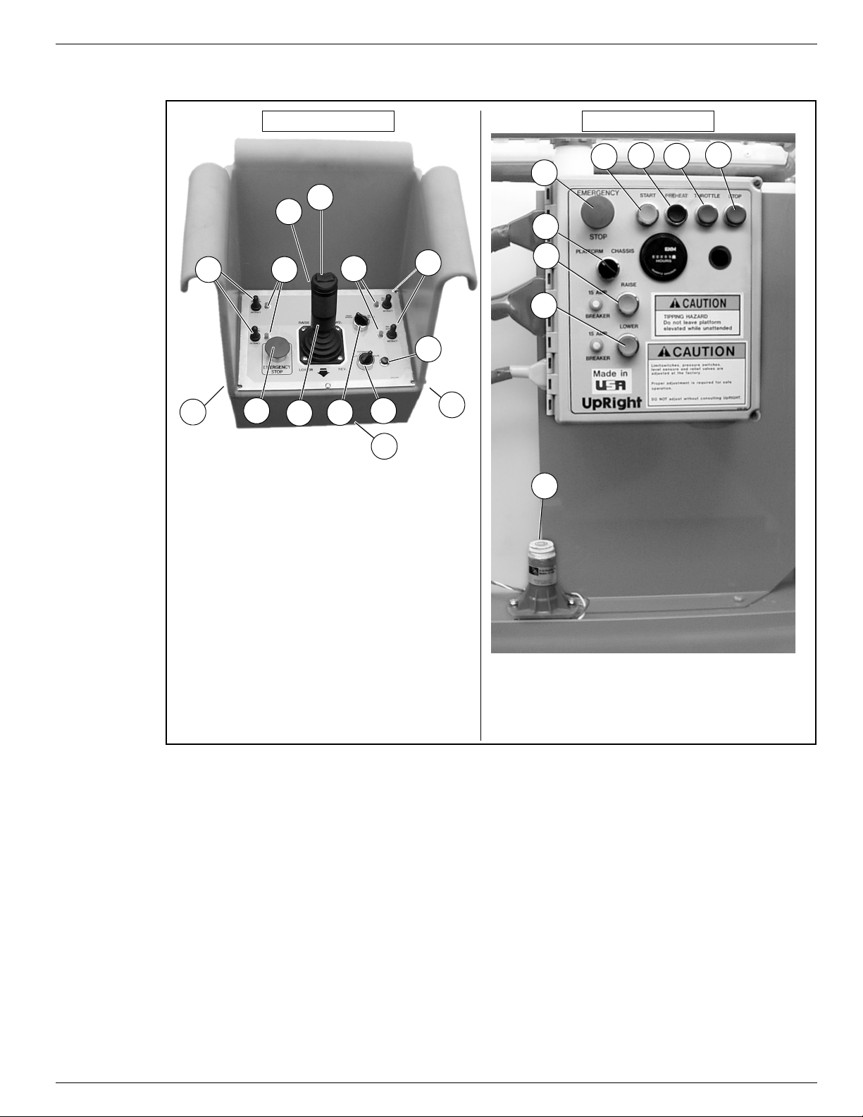
1 Steering Switch
2. Interlock Lever Switch
3. Control Lever
4. Outrigger Switches
5. Outrigger Indicator Lights
6. Emergency Stop Switch
7. Lift/Drive Switch
8. Drive Speed/Torque Selector Switch
9. Drive Enable Indicator
10. Key Switch
11. Glow Plug Button
12. Horn Button
6
11
1Emergency Stop
2. Platform/Chassis Switch
3. Raise Button
4. Lower Button
5. Start Button
6. Glow Plug Button
7. Throttle Button
8. Stop Button
9. Level Sensor
7
1
2
3
4
5
6
8
9
Platform Controls Chassis Controls
12
C
ONTROLS
AND
I
NDICATORS
Figure 2:
Controls and Indicators
Operator Manual Page 5
Page 8
067903-025 LX31/LX41/LX50 Pre-Operation & Safety Inspection
CAUTION
!
!
WARNING
!
!
P
RE
-O
PERATION
Carefully read, understand and follow all safety rules, operating instructions, labels and National Safety
NOTE:
Instructions/Requirements. Perform the following steps each day before use.
1. Open modules and inspect for damage, fluid leaks or missing parts.
2. Check the hydraulic fluid level sight gauge on the hydraulic tank with the platform fully lowered. Add
fluid if necessary.
3. Check that fluid level in the battery is correct (see “Battery Maintenance” on page 16).
4. Check the engine oil level and fuel level.
5. Check that all guardrails are in place, the slide-out deck extension is secured with the pin, and all fasteners are properly tightened.
6. Check tire pressure: 3,4 bar (
7. Carefully inspect the entire work platform for damage such as cracked welds or structural members,
loose or missing parts, fluid leaks, damaged cables or hoses, loose connections and tire damage.
8. While the engine is cool, check the engine coolant level.
& S
AFETY
50 psi
I
NSPECTION
).
S
YSTEM
DO NOT check coolant when engine or radiator is hot; hot coolant can cause severe burns.
F
UNCTION
STAND CLEAR of the work platform while performing the following checks.
Before operating the work platform, survey the work area for surface hazards such as holes, drop-offs,
bumps and debris.
Check in ALL directions, including above the work platform, for obstructions and electrical conductors.
Protect control console cable from possible damage while performing checks.
1. Move the machine, if necessary, to an unobstructed area to allow for full elevation.
2. Place chassis and platform emergency stop switches in the ON position (Figure 2) by pulling the buttons out.
3. Verify that the Platform/Chassis switch is set to PLATFORM.
4. Turn the Platform Controls key switch clockwise to ON. Turn fully clockwise to start the engine, releasing the key once the engine starts.
If the engine is cold, depress the glow plug button and hold for 6 seconds to heat the glow plugs.
NOTE:
I
NSPECTION
5. Position the Lift/Drive switch to the DRIVE position. The drive enable light should be ON.
6. With the speed range switch first in HIGH TORQUE and then in HIGH SPEED, depress the interlock
lever switch and slowly push the control lever to FORWARD then REVERSE positions to check for
speed and directional control. The farther you push or pull the control lever, the faster the machine will
travel.
7. Depress the interlock lever switch and push the steering switch RIGHT then LEFT to check for steering
control.
Page 6 Operator Manual
Page 9

System Function Inspection 067903-025 LX31/LX41/LX50
8. Optional Outrigger Equipped Machines:
a. With the Lift/Outrigger/Drive switch in DRIVE, depress the interlock lever switch on the control lever
and position each Outrigger switch to the EXTEND position.
• Outriggers should be disabled. If an outrigger extends during this test
from service until it is repaired.
b. Turn the Drive/Outrigger/Lift switch to OUTRIGGER.
c. Depress the interlock lever switch on the control lever and position each Outrigger switch to the
EXTEND position to deploy all four (4) outriggers.
• Check the outrigger indicator lights; they should be ON.
d. Depress the Interlock Lever switch on the control lever and position each Outrigger switch to the
RETRACT position.
• Partially retract all four (4) outriggers. The outrigger indicator lights should FLASH.
• Fully retract all four (4) outriggers. The outrigger indicator lights should be OFF.
9. Open the Control Module covers to gain access to the chassis controls and level sensor.
10. Turn the Platform/Chassis switch to CHASSIS.
11. Push the throttle button in. Push the Raise button to elevate platform while pushing the level sensor off
of level. The platform should only partially elevate and the tilt alarm should sound. If the platform continues to elevate and/or there is no alarm,
12. Release the level sensor and fully elevate the platform.
13. Visually inspect the elevating assembly, lift cylinder, cables and hoses for damage or erratic operation.
Check for missing or loose parts.
14. Lower the platform partially by pushing in on the Lower button, and check operation of the audible lowering alarm.
15. Open the chassis emergency lowering valve to check for proper operation (refer to “Emergency Lowering” on page 11). Once the platform is fully lowered, close the valve by releasing the knob.
16. Turn the Platform/Chassis switch to PLATFORM.
17. Close and secure the module covers.
18. Enter the platform making sure the gate is latched.
19. Position the Lift/Drive switch to LIFT.
20. Depress the interlock lever switch and slowly push the control lever to UP to raise the platform; fully actuate the control lever to check proportional lift speed. Slowly pull the control lever to the DOWN position to
lower the platform. Check that the lowering alarm sounds.
21. Optional Outrigger Equipped Machines:
a. With the Lift/Outrigger/Drive switch in LIFT, depress the interlock lever switch on the control lever and
position any outrigger switch to the EXTEND position.
• Outriggers should be disabled. If an outrigger extends during this test,
and remove the machine from service until it is repaired.
22. Turn the controller key switch to OFF, push the Emergency Stop button, and dismount the platform.
and remove the machine from service until it is repaired.
STOP
. Remove the machine
STOP
. Lower the platform
STOP
Operator Manual Page 7
Page 10

067903-025 LX31/LX41/LX50 Operation
WARNING
!
!
O
PERATION
Before
NOTE:
any deficiencies have been corrected, and the operator has been thoroughly trained on this machine.
Never operate the work platform with the parking brakes released. Serious injury or damage could
result.
T
RAVEL
1. Verify the following:
• the chassis Emergency Stop button is in the ON position (pull out)
• the drive enable indicator is ON
• the Platform/Chassis switch is on PLATFORM.
NOTE:
are fully retracted.
operating the work platform, ensure that the pre-operation and safety inspection has been completed,
WITH
If the drive enable indicator is OFF, verify that the platform is fully lowered and (if so equipped) the outriggers
P
LATFORM
L
OWERED
2. After mounting the platform, close and latch the gate. Check that the guardrails are in position and
properly assembled, with the fasteners properly torqued.
3. Check that the route is clear of persons, obstructions, holes and drop-offs, and is capable of supporting
the wheel loads.
4. Check clearances above, below and to the sides of the platform.
5. Pull the controller Emergency Stop button out to the ON position.
6. Turn the controller key switch fully clockwise to start the engine, releasing the key once the engine
starts.
If the engine is cold, hold the glow plug button in for 6 seconds to heat the glow plugs.
NOTE:
7. Set the Lift/Drive switch to DRIVE.
8. Set the speed range switch to HIGH TORQUE.
9. Grasp the control lever so that the interlock lever switch is depressed (releasing the interlock lever
switch cuts power to controller). Slowly push or pull the control lever to FORWARD or REVERSE to
travel in the desired direction. The farther you push or pull the control lever from center, the faster the
machine will travel.
10. While moving, push the speed range switch to HIGH SPEED for travel on level surfaces or to HIGH
TORQUE for climbing grades or traveling in confined areas.
Page 8 Operator Manual
Page 11

Operation 067903-025 LX31/LX41/LX50
T
RAVEL
Travel with the platform elevated
The work platform will travel at reduced speed when in the elevated position, and only if the front axle is
NOTE:
parallel with the rear axle.
1. Check that the route is clear of persons, obstructions, holes and drop-offs, is level and capable of supporting the wheel loads.
2. Check clearances above, below and to the sides of the platform.
3. Position the Lift/Drive switch to the DRIVE position.
4. Push the control lever to FORWARD or REVERSE for the desired direction of travel.
5. If the machine quits driving and the tilt alarm sounds, immediately lower the platform and move the
machine to a level location before re-elevating the platform.
S
TEERING
Push the steering switch
insure proper direction.
WITH
W
ORK
RIGHT
P
LATFORM
on firm and level surfaces.
ONLY
or
to turn the wheels. Observe the tires while maneuvering to
LEFT
E
LEVATED
Steering is not self-centering. Wheels must be returned to the straight ahead position by operating the steering
NOTE:
switch.
R
AISING AND
The machine must be on a firm, level surface, capable of supporting the weight of the machine. On
machines equipped with optional outriggers, use the outriggers to level the machine (refer to “Leveling the
Platform (Outrigger equipped machines only)” on page 10.
1. Position the Lift/Drive switch to LIFT.
2. While holding the control lever so the interlock lever switch is depressed, push the control lever slowly to
UP to raise the platform. Pushing the control lever farther increases the lift speed.
3. When the work task is completed, position the Lift/Drive switch to LIFT, and lower the platform by pulling
back on the control lever until the platform is fully lowered.
L
OWERING
THE
P
LATFORM
Operator Manual Page 9
Page 12
067903-025 LX31/LX41/LX50 Operation
WARNING
!
!
L
EVELING
(O
UTRIGGER
When using outriggers, all four (4) outriggers must be in firm contact with the supporting surface.
THE
P
LATFORM
EQUIPPED
MACHINES
ONLY
)
UTRIGGER SWITCHES AND INDICATOR
O
For each outrigger, there is an outrigger switch and an outrigger indicator light (refer to Figure 2).
Each outrigger switch will raise and lower one outrigger.
Each outrigger indicator light will indicate the position of one outrigger.
• When the indicator light is OFF - the outrigger is fully retracted.
• When the indicator light is FLASHING - the outrigger is partially extended.
• When the indicator light is ON - the outrigger is in firm contact with the supporting surface.
EVEL THE PLATFORM
TO L
1. Make sure that the extension deck is retracted before operating the outriggers.
2. Look around the machine; make sure that there is nothing obstructing the
outriggers, and that the surface beneath them is suitable to support the
weight of the machine.
3. Position the Lift/Outrigger/Drive switch set to OUTRIGGER.
4. Depress the interlock lever switch on the control lever, and operate the
outrigger switches to extend each outrigger until it is making firm contact
with the supporting surface.
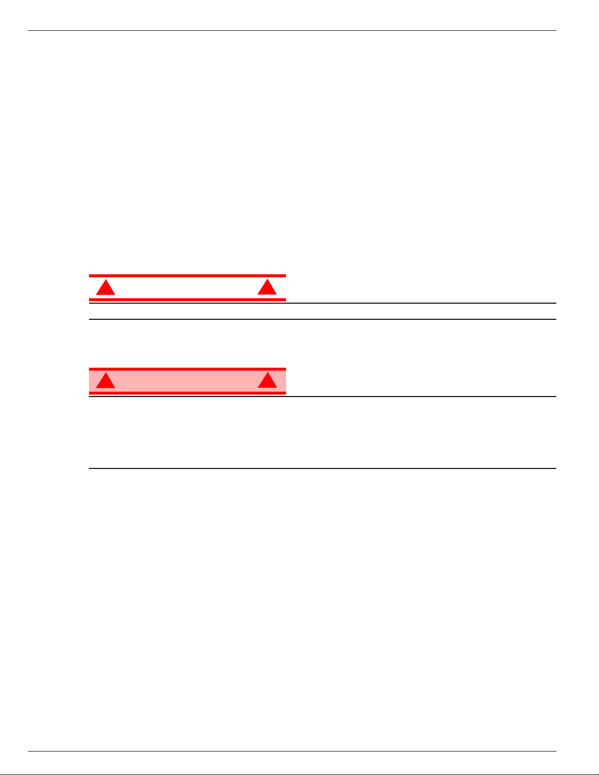
5. While observing the bubble level on the guardrail, extend the outrigger
opposite the position of the bubble until the platform is level. For example:
if the bubble is to the front and left in the orbit, extend the rear right outrigger. Continue to adjust until
the bubble is centered in the small circle indicating that the platform is level.
6. Confirm that all four (4) outriggers are in firm contact with the supporting surface. The outriggers are in
contact with the supporting surface when the indicator lights are ON.
XTEND THE
(E
IGHTS
L
UTRIGGERS
O
)
Figure 3:
Platform Orbit Bubble Level
TO R
Page 10 Operator Manual
ETRACT THE OUTRIGGERS
1. Fully lower the platform.
2. Position the Lift/Outrigger/Drive switch set to OUTRIGGER.
3. Depress the interlock lever switch on the control lever, and position each outrigger switch to RETRACT.
• The outrigger indicator lights will be OFF when the outriggers are fully retracted.
• The drive enable indicator light will not come on until all four outriggers are fully retracted.
Page 13
Operation 067903-025 LX31/LX41/LX50
E
MERGENCY
L
OWERING
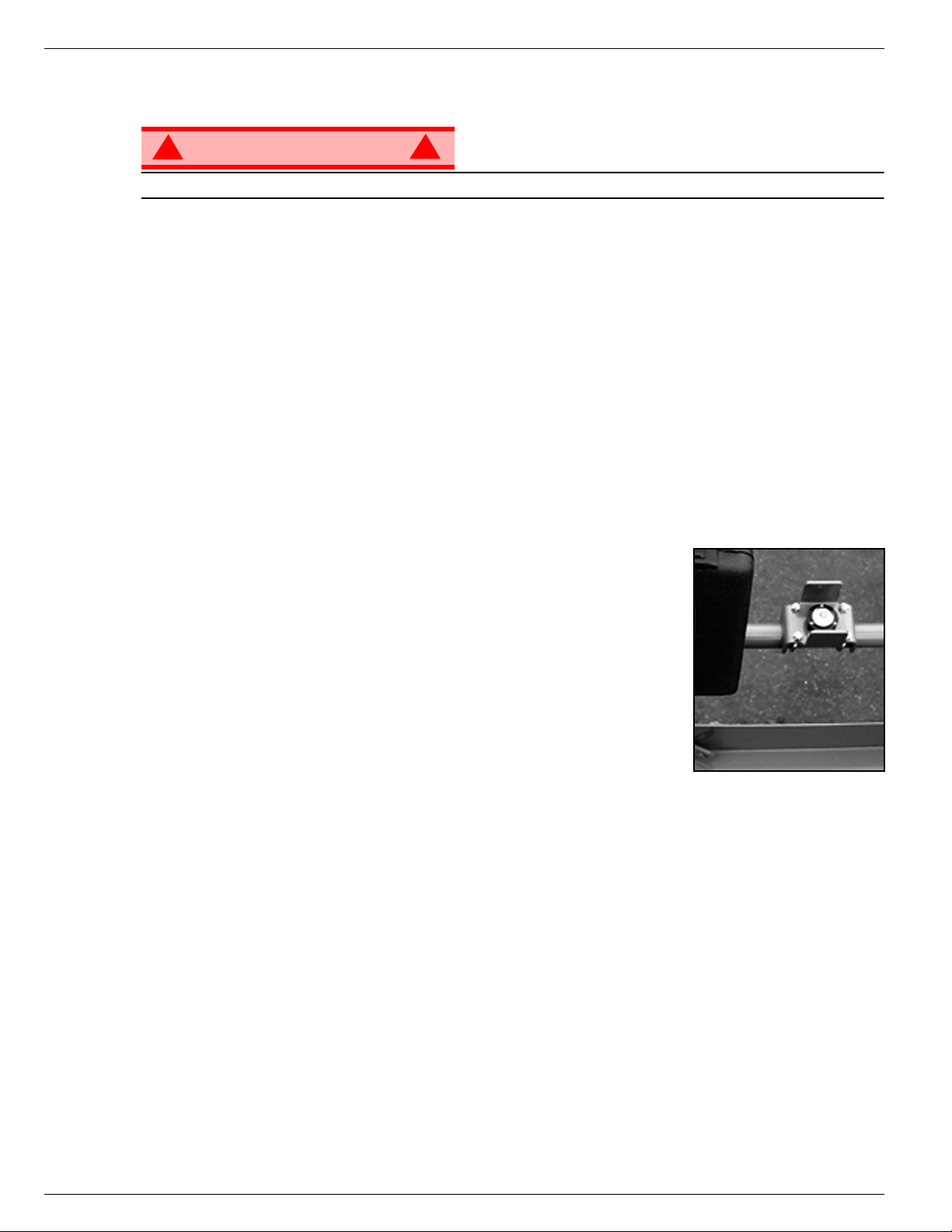
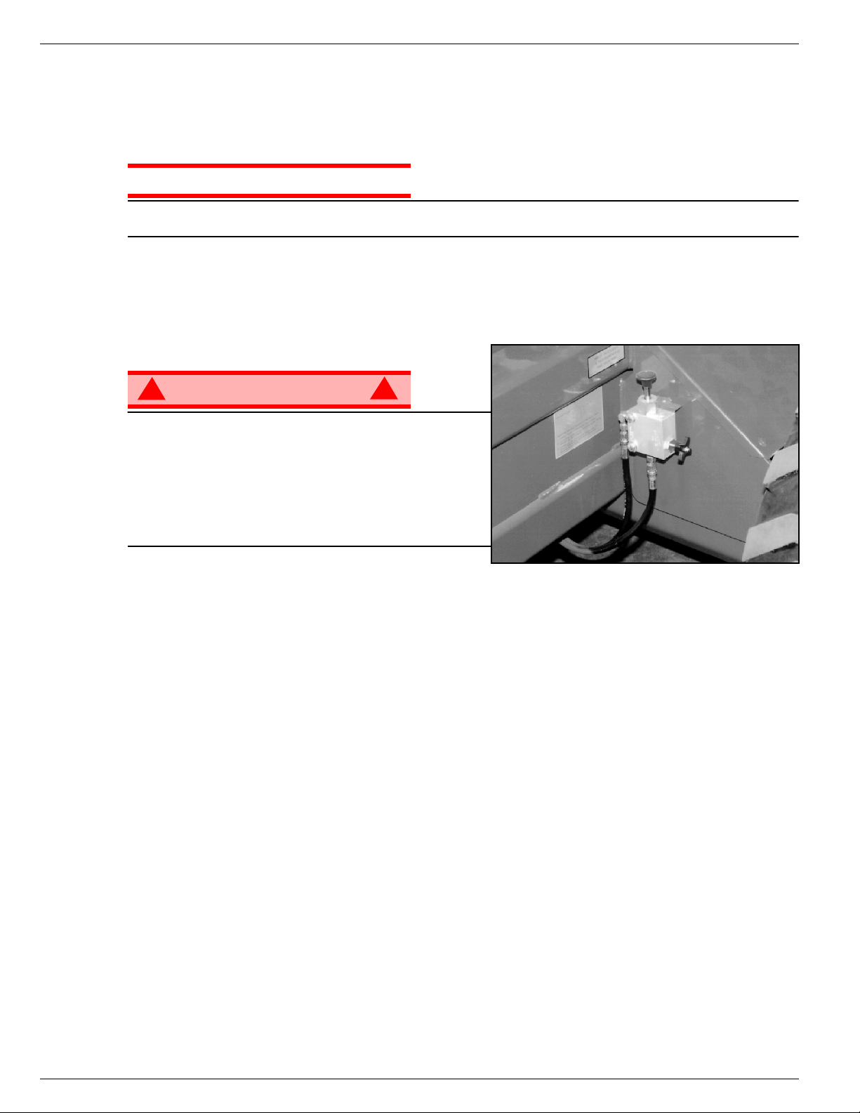
LX31
1. Open the emergency lowering valve by pulling on the
2. Once the platform is fully lowered, release the knob to
AND
LX41
The emergency lowering control knob is located at the
rear of the machine at the base of the scissor assembly.
knob and holding it.
close the valve.
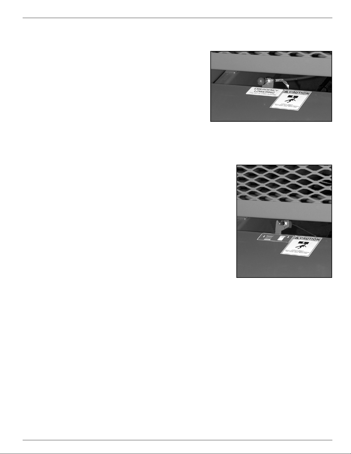
LX50
The emergency lowering control switch is located at the rear of the
machine at the base of the scissor assembly.
1. Open the emergency lowering valve by pushing down on the toggle switch and holding it.
2. Once the platform is fully lowered, release the toggle switch to
close the valve.
Figure 4:
Emergency Lowering Valve, LX31 and LX41
Figure 5:
Emergency Lowering, LX50
Operator Manual Page 11
Page 14
067903-025 LX31/LX41/LX50 Towing or Winching
CAUTION
WARNING
!
!
T
OWING
OR
W
INCHING
Perform the following only when the machine will not operate under its own power and it is necessary to
move the machine or when winching onto a transport vehicle (see “Transporting the Work Platform” on
page 14).
DO NOT tow or winch the machine faster than 0,3 m/s (1 ft./s). Faster speeds will damage drive
components and void the warranty.
P
ARKING
Never operate the work platform with the parking
brakes released. Serious injury or damage could
result.
Never release the brakes if the machine is on a slope.
Chock the wheels before releasing the parking brakes.
Hook the machine to a towing vehicle before releasing
the parking brakes.
B
RAKE
R
ELEASE
Figure 6:
Parking Brake Release Pump
A
FTER
1. Close the needle valve by turning the knob clockwise.
2. Pump the brake release pump until the parking brakes release and the wheels can be turned.
3. The machine will now roll when pushed or pulled.
4. Be sure to open the needle valve and verify that the parking brakes have engaged before the machine
is operated.
U
SE
E
ACH
1. Ensure that the platform is fully lowered.
2. Park the machine on level ground, preferably under cover, secure against vandals, children or unauthorized operation.
3. Turn the key switch to OFF and remove the key to prevent unauthorized operation.
D
AY
Page 12 Operator Manual
Page 15
Fold Down Guardrails 067903-025 LX31/LX41/LX50
WARNING
!
!
F
OLD
D
OWN
This procedure is only for passing through doorways. Guardrails must be returned to proper position
before using the machine.
G
UARDRAILS
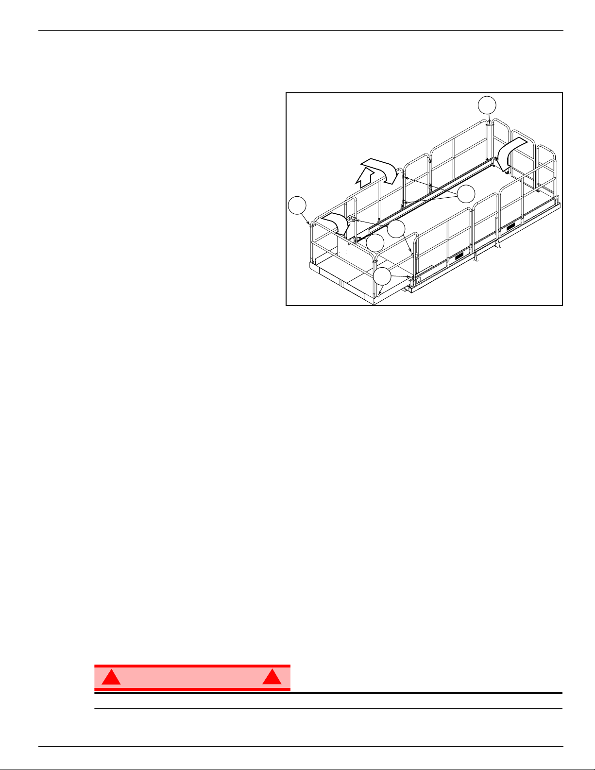
Figure 7:
Fold Down Guardrails
F
OLD
P
NOTE:
1. Place the controller on the platform.
2. Starting at the slide-out deck:
3. Go to the rear of the platform:
4. Unlatch the side gate so the left side guardrails can be folded down in two separate pieces. Also remove
5. Fold the rear half of the side guardrails onto the deck:
6. Fold the front half of the side guardrails onto the deck:
7. Lift up and fold down the front slide-out deck guardrail.
D
OWN
ROCEDURE
When performing the following
procedures, retain all fasteners.
• remove nuts, bolts and washers
from the top front corners of guardrails (A)
• remove the nuts, bolts and washers
from the slide-out deck side guardrail mid-rails (B)
• remove nuts, bolts and washers
located at the top of the sockets that
hold the slide-out deck side guardrails to the deck (C)
• fold the side guardrails down onto
the slide-out deck platform
• leave the end rail up and slide the deck all the way in.
• close and latch the rear gate
• remove the nuts, bolts, washers, and corner brackets from the top of the rear guardrail
• fold the rear guardrail down onto the platform, being careful to keep the gate latched.
the nuts, bolts and washers opposite the gate latch on the right side guardrail so it too can be separated
into two pieces (E).
• lift up and fold down so the guardrails rest on the deck, on top of the rear guardrail.
• lift up and fold down so the guardrails rest on the slide-out deck, with the guardrail posts resting in the
cutouts on the slide-out deck toeboard (F).
A
B
C
F
D
E
E
RECTION
1. Raise the front guardrail, making sure it is pushed down to secure the guardrail in the vertical position.
2. Raise the side guardrails, making sure each is pushed down to secure the guardrail in the vertical position; align holes and install bolts, washers and nuts. Tighten securely.
3. Raise one of the slide-out deck side guardrail assemblies; align holes and install bolts, washers and
nuts. Tighten securely. Repeat this procedure for the other slide-out deck side guardrails.
4. Raise the rear guardrail, and install the corner brackets, nuts, bolts and washers.
5. Hang the controller from the front guardrail.
6. Before operating work platform check that all fasteners are in place and properly torqued.
Before operating machine, guardrails must be securely fastened in their proper position.
Operator Manual Page 13
P
ROCEDURE
Page 16
067903-025 LX31/LX41/LX50 Transporting the Work Platform
CAUTION
T
RANSPORTING
P
REPARATION
1. Fully lower the platform.
2. Disconnect the battery negative (-) lead from the battery terminal.
3. Band the controller to the front guardrail.
4. Band the elevating linkage to the frame.
L
IFTING
1. Secure straps to chassis tie down/lifting
2. Place the platform onto the transport vehi-
3. Chock the wheels.
4. Secure the work platform to the transport
lugs only.
cle in transport position.
vehicle with chains or straps of adequate
load capacity attached to the chassis tie
down/lifting lugs.
THE
BY C
W
FOR
RANE
ORK
P
S
HIPMENT
LATFORM
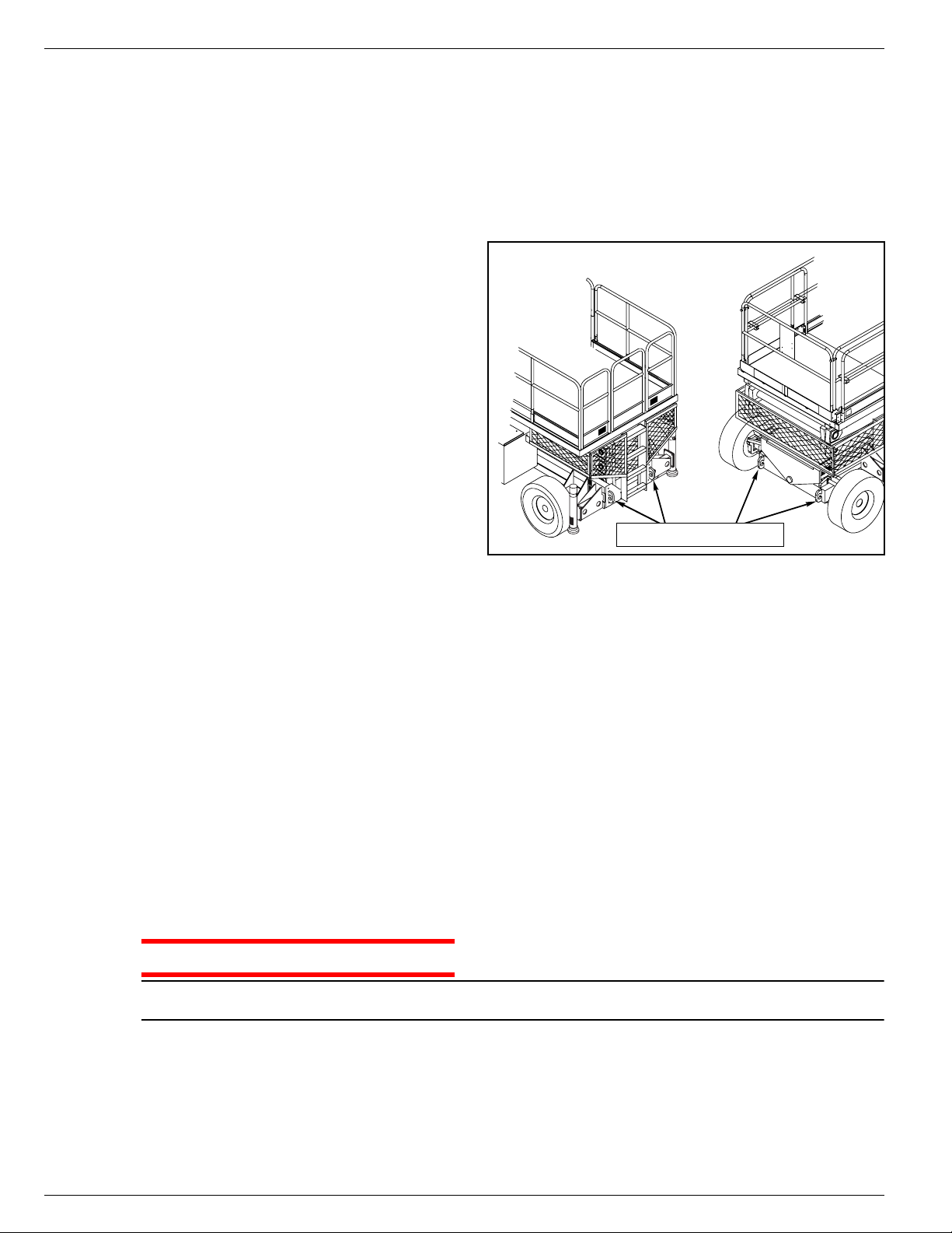
Rear View
Figure 8:
Front View
Transporting Work Platform
Tie Downs/Lifting Lugs
D
RIVING OR
Do not winch faster than 0,3 m/s
NOTE:
1. Move the machine onto the truck or trailer;
A. To
B. To
2. Secure the work platform to the transport vehicle with chains or straps of adequate load capacity
Drive
a. Move the work platform up the ramp and into transport position.
b. Set the wheels straight and turn off the machine.
c. Chock the wheels.
Winch
a. Move the work platform up to the ramp.
b. Attach the winch cable to the tie down/lifting lugs.
c. Release the parking brakes (refer to “Towing or Winching” on page 12).
d. Winch the platform into transport position
e. Chock the wheels.
attached to the chassis tie down/lifting lugs.
W
INCHING
the machine onto the transport vehicle:
the machine onto the transport vehicle:
(1 ft/s)
ONTO
.
A T
RUCK
OR
T
RAILER
Overtightening of chains or straps through tie down/lifting lugs may result in damage to the work
platform.
Page 14 Operator Manual
Page 17
Maintenance 067903-025 LX31/LX41/LX50
WARNING
!
!
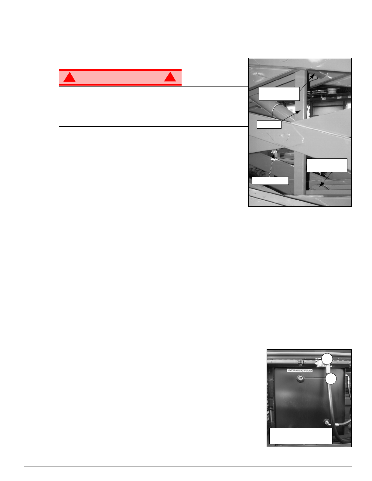
Lower Scissor
Center Pivot
Upper Scissor
Center Pivot
Brace
Locking Pin
2
1
1. Fluid Sight Gauge
2. Filler Cap
M
AINTENANCE
B
LOCKING
Never perform service on the work platform in the elevating
assembly area while the platform is elevated without first blocking
the elevating assembly.
DO NOT stand in elevating assembly area while deploying or
storing brace.
RACE INSTALLATION
B
1. Park the work platform on firm, level ground.
2. Verify that the platform Emergency Stop button is ON.
3. Turn the Platform/Chassis switch to CHASSIS.
4. Start the engine, using the chassis controls.
5. Push the Throttle button in. The button will stay in and the
engine speed will increase. Using the Raise button, elevate the
platform until the scissor brace can be rotated to the vertical
position.
6. From the left side of the machine, disengage the locking pin securing the brace. Rotate the scissor brace
counterclockwise until it is vertical and between the two scissor center pivots.
7. Push the Lower button and gradually lower the platform until the brace is supporting the platform.
8. Disengage the throttle by pushing the Throttle button in again. The button will retract and the engine will
come to idle speed.
THE
E
LEVATING
A
SSEMBLY
Figure 9:
Blocking Elevating Assembly
RACE
B
1. Using the chassis controls, gradually raise the platform until the scissor brace clears the two scissor center pivots.
2. Rotate the scissor brace clockwise until the locking pin engages.
3. Push the Lower button to completely lower the platform.
4. Make sure the Throttle button is disengaged and Platform/Chassis switch is on PLATFORM.
H
YDRAULIC
The hydraulic fluid tank is located in the Power Module.
Never add fluid if the platform is elevated.
NOTE:
1. Make sure that the platform is fully lowered.
2. Check fluid level by observing the fluid sight gauge
3. Remove the filler cap to fill with the appropriate fluid.
EMOVAL
R
F
LUID
Figure 10:
Hydraulic Fluid Tank
Operator Manual Page 15
Page 18
067903-025 LX31/LX41/LX50 Maintenance
WARNING
!
!
B
ATTERY
Hazard of explosive gas mixture. Keep sparks, flame, and smoking
material away from battery.
Always wear safety glasses when working with batteries.
Battery fluid is highly corrosive. Thoroughly rinse away any spilled
fluid with clean water.
Always replace batteries with UpRight batteries or manufacturer
approved replacements.
Check battery fluid level weekly, especially if the work platform is
being used in a warm, dry climate.
M
AINTENANCE
Figure 11:
Battery Location
If the electrolyte level is lower than 10 mm (
add distilled water ONLY. Do not use tap water with high mineral
content; it will shorten battery life.
The battery and cables should be inspected regularly for signs of
cracks in the case, electrolyte leakage and corrosion of the terminals. Inspect the cables for worn spots or breaks in the insulation
and for broken cable terminals.
Refer to the Service Manual to extend battery life and for complete service instructions.
) above plates,
3/8 in.
Page 16 Operator Manual
Page 19
Maintenance 067903-025 LX31/LX41/LX50
CAUTION
!
!
E
NGINE
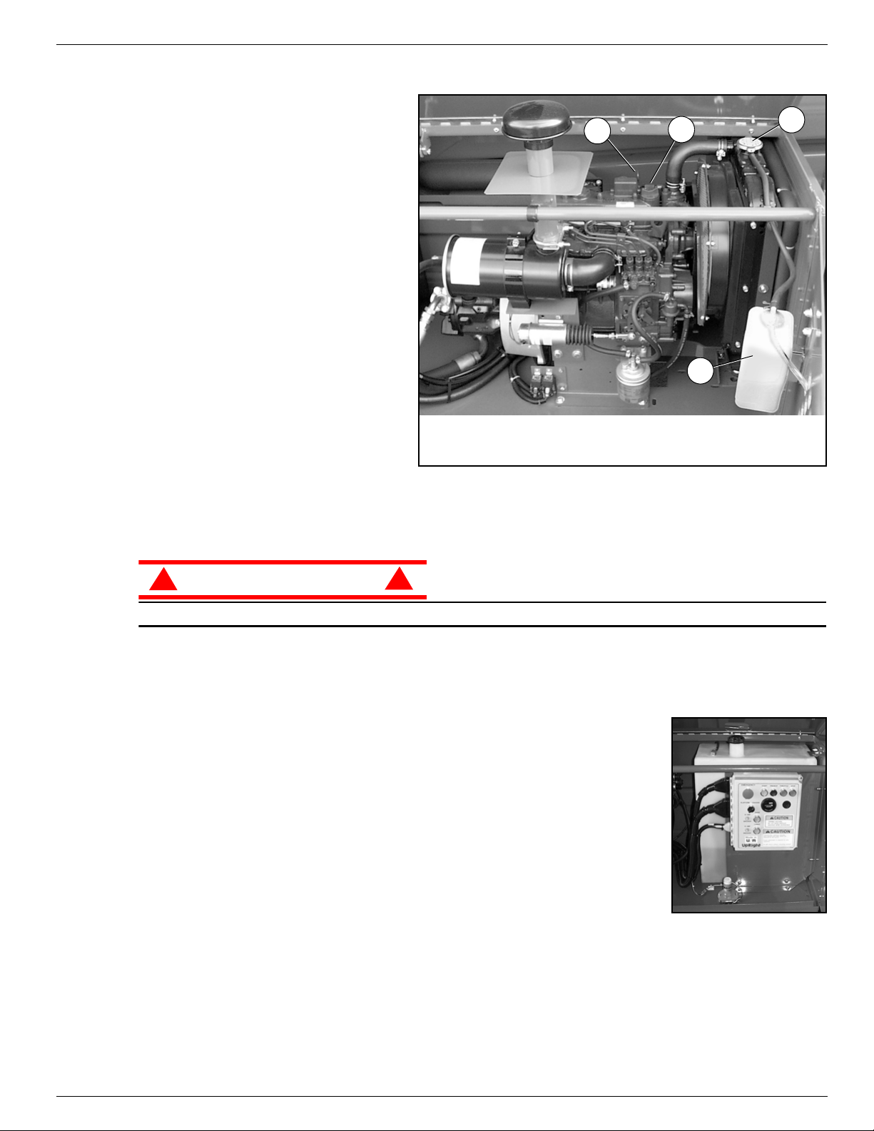
Figure 12:
OOLANT
C
The coolant recovery tank is mounted
on the inside of the door of the power
module.
1. Remove the cap on the coolant
recovery tank.
2. Add coolant to the “FULL” mark.
Never remove the radiator cap when the
NOTE:
engine is hot.
IL
O
The engine
you check and replenish the engine oil.
Refer to the Service Manual to change
the oil filter.
1. Remove the oil dipstick and check the
level indicator marks.
2. If the level is low, remove the oil filler cap.
3. Replenish with the proper engine oil (refer to the engine service manual that came with the machine).
must not be running
when
1 Radiator Cap
2. Coolant Recovery Tank
4
3
2
3. Oil Filler Cap
4. Oil Dipstick
Engine
1
DO NOT check coolant when engine or radiator is hot; hot coolant can cause severe burns.
UEL
F
The fuel tank for is located in the Control Module, behind the chassis controls.
The tank is translucent. Check the fuel level by observing the level of the liquid
through the tank.
Figure 13:
Fuel Supply
Operator Manual Page 17
Page 20
067903-025 LX31/LX41/LX50 Preventative Maintenance Schedule
WARNING
!
!
P
REVENTATIVE
M
AINTENANCE
S
CHEDULE
The complete inspection consists of periodic visual and operational checks, along with periodic minor
adjustments to assure proper performance. Daily inspection will prevent abnormal wear and prolong the
life of all systems. The inspection and maintenance schedule is to be performed at regular intervals.
Inspection and maintenance shall be performed by personnel who are trained and familiar with mechanical and electrical procedures.
Before performing preventative maintenance, familiarize yourself with the operation of the machine.
Always block the elevating assembly whenever it is necessary to enter the scissor assembly to perform
maintenance while the platform is elevated (see page 15).
The daily preventative maintenance table has been designed for machine service and maintenance
repair. Please photocopy the Daily Preventative Maintenance Check List and use the table as a checklist
when inspecting the machine for service.
D
AINTENANCE
M
AILY
P
REVENTATIVE
ABLE KEY
T
M
AINTENANCE
AINTENANCE
M
C
R
HECK
EPORT
L
IST
\
Y = Yes/Acceptable
N = No/Not Acceptable
R = Repaired/Acceptable
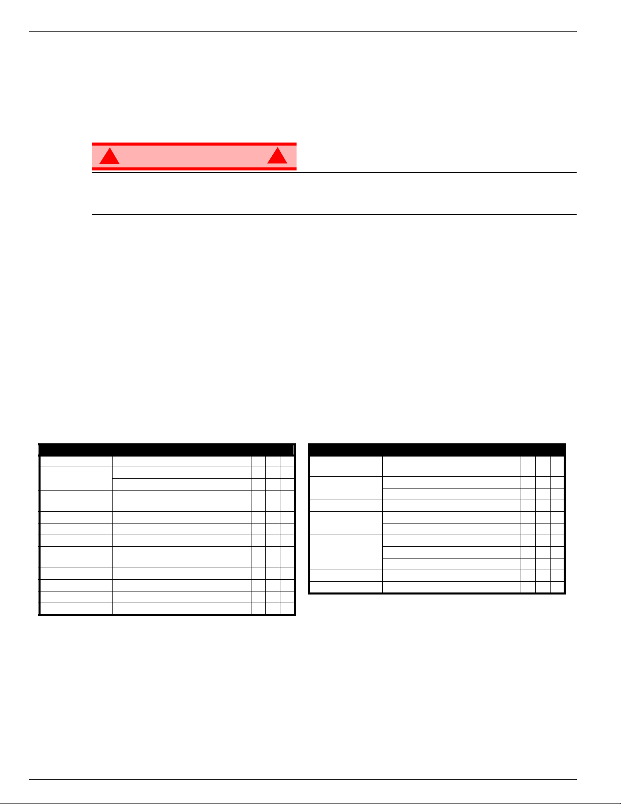
COMPONENT INSPECTION OR SERVICES Y N R
Battery Check electrolyte level
Chassis
Control Cable
Controller Check switch operation
Drive Motors Check for operation and leaks
Elevating Assembly Inspect for structural cracks
Emergency Lowering
System
Entire Unit Check for and repair collision damage
Hydraulic fluid Check fluid level
Hydraulic Pump Check for hose fitting leaks
Hydraulic System Check for leaks
Check hoses for pinch or rubbing points
Check welds for cracks
Check the exterior of the cable for pinching,
binding or wear
Operate the emergency lowering valve and
check for serviceability
Date: _______________________________________
Owner: _____________________________________
Model No: ___________________________________
Serial No: ___________________________________
Serviced By: _________________________________
COMPONENT INSPECTION OR SERVICES Y N R
Labels
Platform Deck and
Rails
Tires and Wheels Check for damage
Engine Oil and Filter
Engine Fuel System
Engine Coolant Check coolant level (with engine cold)
Torque Hubs Check for leaks
Check for peeling, missing, or unreadable
labels & replace
Check welds for cracks
Check condition of deck
Check level and condition
Check for leaks
Check fuel level
Check for leaks
Check air cleaner
Page 18 Operator Manual
Page 21

Preventative Maintenance Schedule 067903-025 LX31/LX41/LX50
NNNN
OOOOTTTTEEEESSSS
::::
Operator Manual Page 19
Page 22
067903-025 LX31/LX41/LX50 Labels
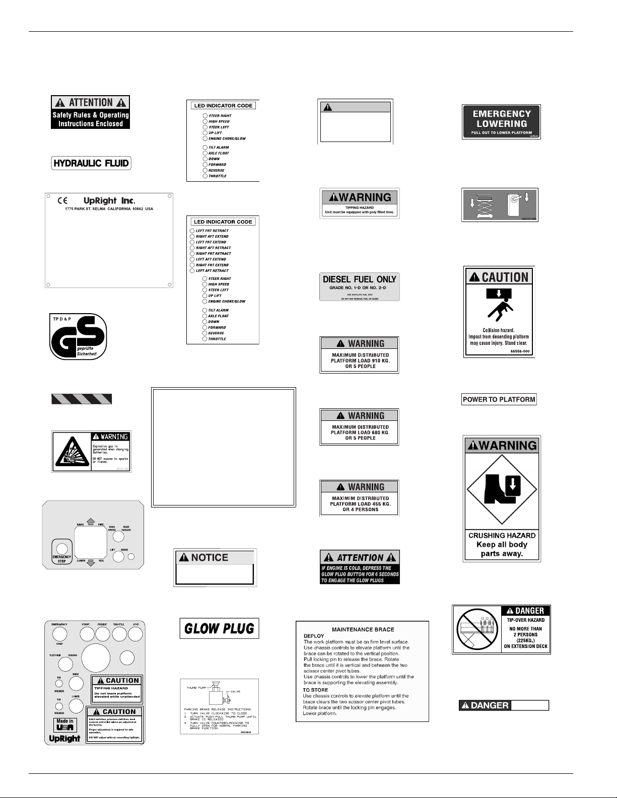
L
ABELS
These labels shall be present and in good condition before operating the work platform. Be sure to read,
understand and follow these labels when operating the work platform.
WARNING
TIPPING HAZARD
Check tire pressure daily.
Pressure must be
2
010076-001
060197-000
4
Model______________ Serial number:___________
Machine weight _______kg Mfg. date:_________
Maximum wheel load:________
Maximum allowable incline of machine when elevated:_____de g.
Occupants and equipment must not exceed the rated maximum
load:_____kg Maximum platform occupants: _____
Maximum allowable sIde force on platform:_____N
Maximum platform height:______m
Maximum platform reach:______m
Maximum allowable wind speed: ______m/s=Beaufort scale_____
Maximum hydraulic system pressure:_____bar
Maximum system voltage: _______Vdc
This machine is manufactured to comply with
Machinery directive 89-392/CEE
CAUTION: CONSULT OPERATOR'S MANUAL BEFORE USE.
5
061205-003
061205-003
067480-000
13
maintained at 50 P.S.I.
LX31/LX41:
22
066562-000
LX50:
22
066562-003
LX31/LX41:
40
066558-001
LX50:
40
005223-908
6
030768-002
7
064936-099
9
066552-000
11
067642-011
(Outrigger Units:
067642-004)
13
067480-001
(Outrigger Units)
USE OF THE AERIAL WORK PLATFORM: This aerial work platform is intended to lift persons and
their tools as well as the material used for the job. IT IS designed for repair and assembly jobs and
assignments at overhead workplaces (ceilings, cranes, roof structures, buildings etc.). All other uses
of the aerial work platform ARE PROHIBITED!
THIS AERIAL WORK PLATFORM IS NOT INSULATED! For this reason it is imperative to keep a safe
distance from live parts of electrical equipment!
ALL occupants must wear an approved fall restraint properly attached to a designated platform
anchorage point. Attach only one fall restraint to each anchorage point.
Exceeding the specified permissible maximum load on the platform IS PROHIBITED!
The use and operation of the aerial work platform as a lifting tool or a crane (lifting of loads from
below upwards or from up high on down) IS PROHIBITED!
NEVER exceed 400 N of side force.
DISTRIBUTE all platform loads evenly on the platform.
NEVER operate the machine without first surveying the work area for surface hazards such as
holes, drop-offs, bumps, curbs, or debris; and avoiding them.
OPERATE machine only on surfaces capable of supporting wheel loads.
NEVER operate the machine when wind speeds exceed 28mph (12.5m/sec.=Beaufort scale 6).
IN CASE OF EMERGENCY push emergency stop button to deactivate all powered functions.
Climbing up the railing of the platform, standing on or stepping from the platform onto buildings, steel
or prefab concrete structures, etc., IS PROHIBITED!
Dismantling the swing gate or the liftable bar or other railing components IS PROHIBITED! Always make
certain that the swing gate or the liftable bar is closed and securely locked! IT IS PROHIBITED to keep
the swing gate or the liftable bar in an open position (e.g. held open with tie-straps) when the platform
is raised!
To extend the height or the range by placing of ladders, scaffolds or similar devices on the platform
IS PROHIBITED!
INSPECT the machine thoroughly for cracked welds, loose or missing hardware, hydraulic leaks,loose wire
connections, and damaged cables or hoses before using.
VERIFY that all labels are in place and legible before using.
NEVER use a machine that is damaged, not functioning properly, or has damaged or missing labels.
IF ALARM SOUNDS while platform is elevated, STOP, carefully lower platform. Move machine to a firm,
level surface.
To bypass any safety equipment IS PROHIBITED and presents a danger for the persons on the aerial work
platform and in its working range.
NEVER charge batteries near sparks of open flame. Charging batteries emit explosive hydrogen gas.
067195-001
14
START CIRCUIT PROTECTION
If engine stops cranking while
starting, let machine sit for
10-15 minutes before re-starting
067478-000
15
027898-000
25
LX31: 066557-060
26
LX41: 066557-057
26
26
LX50: 066557-054
067822-001
3434
066556-000
41
068639-000
42
43
066556-001
(Outrigger Units)
067822-000
17
066551-051
44
TIPPING HAZARD
If horn sounds continuously
lower platform and relevel.
066551-003
45
38
067481-001
12
063423-000
21
066561-001
(Outrigger Units)
Page 20 Operator Manual
Page 23

Labels 067903-025 LX31/LX41/LX50
Rear
Figure 14:
Safety Labels Locations
Platform Controls
Power Module
Control Module
Front
Inside
Inside
Chassis Controls
Operator Manual Page 21
Page 24

067903-025 LX31/LX41/LX50 Specifications
S
PECIFICATIONS
Specifications subject to change without notice. Refer to the Service Manual for service and repair information. Refer to the Parts Manual for illustrated parts breakdown. Hot weather or heavy use may reduce
performance. Meets or exceeds all applicable national safety requirements
ITEM LX31 LX41 LX50
Platform Size (Inside toeboards)
Standard
Slide-out Deck Extended
Max. Platform Capacity
Standard
With Rear Deck Option
On Extension
Max. No. of occupants
Standard
With Rear Deck Option
Height
Working Height
Max. Platform Height
Min. Platform Height
Drivable Height
Dimensions
Weight, Standard 2WD:
Weight, Dual Deck 2WD:
Overall Width
Overall Height, guardrails up
Overall Height, guardrails lowered
Overall Length, deck in
Overall Length, deck extended
Surface Speed
Platform Lowered
Platform Raised
System Voltage
Hydraulic Tank Capacity
Maximum Hydraulic System Pressure
Hydraulic Fluid
Normal Temperature: above 0° C [32° F]
Low Temperature: below 0° C [32° F]
Extreme Temperature: below -17° C [0° F]
Lift System
Lift Speed
Power Source
Drive Control
Control System
Horizontal Drive
Tires
Tire Air Pressure
Parking Brakes
Turning Radius (inside)
Maximum Gradeability:
Wheel Base
Ground Clearance
Guardrails
4WD:
4WD:
2WD:
4WD:
2WD:
4WD:
2WD:
4WD:
Noise Level
3,96 m x 1,73 m [
4,83 m x 1,73 [
907 kg [
794 kg [
11,45 m [
4314 kg [
4436 kg [
4645 kg [
4767 kg [
0 to 5,0 km/h [
0 to 0,48 km/h [
107 liters [
207 bar [
One Single Stage Lift Cylinder One Single Stage Lift Cylinder Two Single Stage Lift Cylinders
Raise: 40 sec. Lower: 52 sec. Raise: 45 sec. Lower: 60 sec. Raise: 80 sec. Lower: 112 sec.
Diesel 20 HP Kubota, 3 Cylinder,
Smooth one-hand Joystick Smooth one-hand Joystick Smooth one-hand Joystick
2 Wheel, Hyd. Motors
4 Wheel, Hyd. Motors
10-16.5 NHS 8 Ply 10-16.5 NHS 8 Ply 10-16.5 NHS 8 Ply Poly Filled
Dual Disc, Spring Applied,
1.1 m [
Fold Down with gate.
227 kg [
156 in x 68 in.
190 in. x 68 in.
2,000 lbs.
] 680 kg [
1750 lbs.
] 567 kg [
500 lbs.
] 227 kg [
] 3,96 m x 1,73 m [
] 4,83 m x 1,73 [
156 in x 68 in.
190 in. x 68 in.
1,500 lbs.
1,250 lbs.
500 lbs.
] 3,96 m x 1,73 m [
] 4,83 m x 1,73 [
] 454 kg [
] 341 kg [
] 227 kg [
5 people 5 people 4 people
5 people 4 people 3 people
9,45 m [
1,43 m [
26 ft. 3 in.
8 m [
2,29 m [
2,53 m [
1,64 m [
4,02 m [
4,89 m [
37 ft. 6 in.
56.3 in.
] 14,34 m [
31 ft.
] 12,34 m [
]1,66 m [
] 8 m [
9,511 lbs.
9,780 lbs.
10,241 lbs.
10,440 lbs.
]
5026 kg [
]
]
]
90 in.
]2,29 m [
99.8 in.
] 2,76 m [
64.5 in.
]1,87 m [
160 in.
] 4,02 m [
192 in.
] 4,89 m [
0 to 3.1 mph
0 to 0.5 mph
] 0 to 5,0 km/h [
] 0 to 0,48 km/h [
5357 kg [
5479 kg [
5148kg [
47 ft. 3 in.
40 ft. 6 in.
26 ft. 3 in.
11,080 lbs.
11,349 lbs.
11,810 lbs.
12,079 lbs.
] 17,1 m [
]15,1 m [
65.3 in.
] 1,9 m [
] 8 m [
]
]
]
]
90 in.
] 2,29 m [
109 in.
]3 m [
73.5 in.
] 2,1 m [
160 in.
] 4,02 m [
192 in.
] 4,89 m [
0 to 3.1 mph
0 to 0.5 mph
] 0 to 5,0 km/h [
] 0 to 0,48 km/h [
26 ft. 3 in.
6242 kg [
6364 kg [
6460 kg [
6583 kg [
118.3 in.
12 Volt DC 12 Volt DC 12 Volt DC
28.3 US Gallons
3000 psi
] 207 bar [
] 107 liters [
28.3 US Gallons
3000 psi
] 207 bar [
] 107 liters [
28.3 US Gallons
ISO #46 ISO #46 ISO #46
ISO #32 ISO #32 ISO #32
ISO #15 ISO #15 ISO #15
Water Cooled
Diesel 20 HP Kubota, 3 Cylinder,
Water Cooled
Diesel or HP Kubota, 3 Cylinder, Water Cooled
Proportional Proportional Proportional
50psi.
3,4 bar [
Hydraulic Release
48 in.
1,22 m [
30%
17° [
]
35%
19° [
]
114.5 in.
2,9 m [
116 in.
2,95 m [
9.5 in.
0,24 m [
43.5 in.
] high,
2 Wheel, Hyd. Motors
4 Wheel, Hyd. Motors
]3,4 bar [
50psi.
]NA
Dual Disc, Spring Applied,
Hydraulic Release
17° [
19° [
2,9 m [
2,95 m [
48 in.
30%
35%
114.5 in.
116 in.
9.5 in.
43.5 in.
] 1,22 m [
]
]
]
]
] 0,24 m [
] high,
]1,22 m [
]
]
] 0,24 m [
1.1 m [
Fold Down with gate.
Dual Disc, Spring Applied, Hydraulic Release
2 Wheel, Hyd. Motors
4 Wheel, Hyd. Motors
13,5° [
13,5° [
2,9 m [
2,95 m [
43.5 in.
1.1 m [
Fold Down with gate.
156 in x 68 in.
190 in. x 68 in.
1,000 lbs.
49 ft. 6 in.
750 lbs.
500 lbs.
56 ft.
76 in.
]
]
]
]
]
]
]
13,761 lbs.
14,030 lbs.
14,242 lbs.
14,513 lbs.
90 in.
]
]
]
]
]
]
82.5 in.
]
160 in.
]
192 in.
]
0 to 3.1 mph
0 to 0.5 mph
3000 psi
]
48 in.
]
24%
]
24%
]
114.5 in.
]
116 in.
]
9.5 in.
]
] high,
]
]
]
]
]
Page 22 Operator Manual
Page 25

Tout le personnel doit lire attentivement et respecter toutes les consignes de sécurité avant
Consignes de sécurité
Consignes de sécurité
Consignes de sécuritéConsignes de sécurité
Risque d’électrocution
Risque d’électrocution
Risque d’électrocutionRisque d’électrocution
UIDE DE L’OPÉRATEUR
G
AVERTISSEMENT
d’entretenir ou d’utiliser une plate-forme élévatrice UpRight.
Risque de basculement
Risque de basculement Risque de collision
Risque de basculementRisque de basculement
Risque de collision Risque de chute
Risque de collisionRisque de collision
Risque de chute
Risque de chuteRisque de chute
CETTE MACHINE
N’EST PAS ISOLÉE !
USAGE DE LA PLATE-FORME ÉLÉVAT RI CE
matériaux utilisés sur le chantier. Elle est conçue pour les travaux de réparations et d’assemblage sur les points élevés (plafonds, grues,
charpentes de toit, immeubles, etc.). Tout autre usage de la plate-forme élévatrice est interdit !
CETTE PLATE-FORME ÉLÉVATRICE N’EST PAS ISOLÉE !
équipements électriques sous tension !
Il est interdit
Il est interdit
NE JAMAIS
RÉPA RT I R
NE JAMAIS
bosses, trottoirs ou débris; et les éviter.
N’UTILISER
NE JAMAIS
pour plus de détails.
EN CAS D’URGENCE
SI L’ALARME RETENTIT
une surface plane et ferme.
Il est interdit
préfabriquée, etc. !
Il est interdit
Il est interdit
Il est interdit
NE JAMAIS
d’élévation.
INSPECTER
hydrauliques, de branchements électriques desserrés ou de câbles et flexibles endommagés avant d’utiliser la machine.
VÉRIFIER
NE JAMAIS
endommagés.
Il est interdit
trouvant dans la zone de travail.
NE JAMAIS
gaz explosif.
Sauf autorisation de la part d’UpRight, toute modification de la plate-forme
APRÈS AVOIR UTILISÉ
l’utilisation non autorisée de la plate-forme.
de dépasser la charge maximum admissible. Voir « Limitations particulières » à la page 26 pour plus de détails.
d’utiliser la plate-forme comme appareil de levage ou grue (levage des charges par le dessous ou le dessus) !
dépasser la force manuelle autorisée pour cette machine. Voir « Limitations particulières » à la page 26 pour plus de détails.
uniformément toutes les charges placées sur la plate-forme.
utiliser la machine sans avoir d’abord vérifié si la zone de travail est exempte de dangers tels que des trous, dénivellations,
la machine que sur des surfaces pouvant supporter la charge des roues.
utiliser la machine lorsque la vitesse du vent dépasse les spécifications pour la machine. Voir« Échelle de Beaufort » à la page 26
, appuyer sur le bouton d’ARRÊT D’URGENCE pour désactiver toutes les fonctions.
lorsque la plate-forme est élevée, ARRÊTER, abaisser la plate-forme avec précaution. Conduire la machine jusqu’à
de monter ou de se tenir sur les garde-corps de la plate-forme et de passer de la plate-forme à un immeuble, une structure
de retirer le portillon pivotant ou toute autre pièce de garde-corps ! Toujours vérifier que le portillon est fermé et verrouillé !
de maintenir le portillon pivotant en position ouverte (par exemple au moyen d’attaches) lorsque la plate-forme est élevée !
d’accroître la hauteur ou la portée de la plate-forme au moyen d’échelles, échafaudages ou autres dispositifs similaires !
effectuer de travaux d’entretien sur la machine, si la plate-forme est en position élevée, sans tout d’abord bloquer le dispositif
minutieusement la machine en vue de soudures fissurées, de pièces de boulonnerie manquantes ou desserrées, de fuites
que tous les autocollants sont en place et lisibles avant d’utiliser la machine.
utiliser une machine qui est endommagée, qui ne fonctionne pas correctement ou dont les autocollants sont manquants ou
de mettre tout dispositif de sécurité hors service, ce qui mettrait en danger les personnes à bord de la plate-forme et celles se
charger les batteries à proximité d’étincelles ou d’une flamme vive. Lors de la charge, les batteries dégagent de l’hydrogène, un
la plate-forme élévatrice, mettre les deux contacteurs à clé en position d’arrêt (off), puis retirer la clé afin d’empêcher
NE JAMAIS
conduire la machine avec la plate-forme
élevée si la machine ne se trouve pas sur
élever la plate-forme ou
une surface plane et ferme.
: Cette plate-forme élévatrice est destinée au levage de toute personne, de son outillage et des
C’est pourquoi il est impératif de rester à distance sûre des lignes et
NE JAMAIS
avant de s’être assuré de l’absence
est interdite
positionner la plate-forme
d’obstacles en hauteur
ou autres dangers.
.
NE JAMAIS
debout ou assis sur les rampes
monter, ni se tenir
du garde-corps.
Page 1
Page 26

067903-025 LX31/LX41/LX50
T
ABLE
DES MATIÈRES
Introduction. . . . . . . . . . . . . . . . . . . . . . . . . . . . . . . . . . . . . . . . . . . . . . . . . . . . . . . . . . . . . . . . . . . . . . . . .25
Description générale . . . . . . . . . . . . . . . . . . . . . . . . . . . . . . . . . . . . . . . . . . . . . . . . . . . . . . . . . . . . . . . . .25
Limitations particulières . . . . . . . . . . . . . . . . . . . . . . . . . . . . . . . . . . . . . . . . . . . . . . . . . . . . . . . . . . . . . .26
Tous les modèles . . . . . . . . . . . . . . . . . . . . . . . . . . . . . . . . . . . . . . . . . . . . . . . . . . . . . . . . . . . . . . . . . . . . . . . . . . 26
Capacité de la plate-forme . . . . . . . . . . . . . . . . . . . . . . . . . . . . . . . . . . . . . . . . . . . . . . . . . . . . . . . . . . . . . . . . . . . 26
Force manuelle . . . . . . . . . . . . . . . . . . . . . . . . . . . . . . . . . . . . . . . . . . . . . . . . . . . . . . . . . . . . . . . . . . . . . . . . . . . . 26
Échelle de Beaufort. . . . . . . . . . . . . . . . . . . . . . . . . . . . . . . . . . . . . . . . . . . . . . . . . . . . . . . . . . . . . . . . . . . . . . . . . 26
Alarme de surcharge de levage . . . . . . . . . . . . . . . . . . . . . . . . . . . . . . . . . . . . . . . . . . . . . . . . . . . . . . . . . . . . . . . 26
Commandes et indicateurs . . . . . . . . . . . . . . . . . . . . . . . . . . . . . . . . . . . . . . . . . . . . . . . . . . . . . . . . . . . .27
Inspection de sécurité avant utilisation . . . . . . . . . . . . . . . . . . . . . . . . . . . . . . . . . . . . . . . . . . . . . . . . . .28
Essai de fonctionnement des systèmes. . . . . . . . . . . . . . . . . . . . . . . . . . . . . . . . . . . . . . . . . . . . . . . . . .28
Utilisation . . . . . . . . . . . . . . . . . . . . . . . . . . . . . . . . . . . . . . . . . . . . . . . . . . . . . . . . . . . . . . . . . . . . . . . . . .30
Déplacement avec la plate-forme abaissée . . . . . . . . . . . . . . . . . . . . . . . . . . . . . . . . . . . . . . . . . . . . . . . . . . . . . . 30
Déplacement avec la plate-forme élevée . . . . . . . . . . . . . . . . . . . . . . . . . . . . . . . . . . . . . . . . . . . . . . . . . . . . . . . . 31
Direction . . . . . . . . . . . . . . . . . . . . . . . . . . . . . . . . . . . . . . . . . . . . . . . . . . . . . . . . . . . . . . . . . . . . . . . . . . . . . . . . . 31
Élévation et abaissement de la plate-forme . . . . . . . . . . . . . . . . . . . . . . . . . . . . . . . . . . . . . . . . . . . . . . . . . . . . . . 31
Mise de niveau de la plate-forme
(machines équipées de stabilisateurs seulement) . . . . . . . . . . . . . . . . . . . . . . . . . . . . . . . . . . . . . . . . . . . . . . . . . 32
Commutateurs et témoins de stabilisateurs . . . . . . . . . . . . . . . . . . . . . . . . . . . . . . . . . . . . . . . . . . . . . . . . . . . 32
Mise de niveau de la plate-forme (extension des stabilisateurs) . . . . . . . . . . . . . . . . . . . . . . . . . . . . . . . . . . . 32
Rétraction des stabilisateurs . . . . . . . . . . . . . . . . . . . . . . . . . . . . . . . . . . . . . . . . . . . . . . . . . . . . . . . . . . . . . . 32
Abaissement d’urgence. . . . . . . . . . . . . . . . . . . . . . . . . . . . . . . . . . . . . . . . . . . . . . . . . . . . . . . . . . . . . . . . . . . . . . 33
LX31 et LX41 . . . . . . . . . . . . . . . . . . . . . . . . . . . . . . . . . . . . . . . . . . . . . . . . . . . . . . . . . . . . . . . . . . . . . . . . . . 33
LX50. . . . . . . . . . . . . . . . . . . . . . . . . . . . . . . . . . . . . . . . . . . . . . . . . . . . . . . . . . . . . . . . . . . . . . . . . . . . . . . . . 33
Remorquage ou treuillage . . . . . . . . . . . . . . . . . . . . . . . . . . . . . . . . . . . . . . . . . . . . . . . . . . . . . . . . . . . . .34
Desserrage de frein de stationnement . . . . . . . . . . . . . . . . . . . . . . . . . . . . . . . . . . . . . . . . . . . . . . . . . . . . . . . . . . 34
Après utilisation, tous les jours . . . . . . . . . . . . . . . . . . . . . . . . . . . . . . . . . . . . . . . . . . . . . . . . . . . . . . . .34
Garde-corps rabattables . . . . . . . . . . . . . . . . . . . . . . . . . . . . . . . . . . . . . . . . . . . . . . . . . . . . . . . . . . . . . .35
Repli des
garde-corps . . . . . . . . . . . . . . . . . . . . . . . . . . . . . . . . . . . . . . . . . . . . . . . . . . . . . . . . . . . . . . . . . . . . . . . . . . . . . . . 35
Procédure de mise en place . . . . . . . . . . . . . . . . . . . . . . . . . . . . . . . . . . . . . . . . . . . . . . . . . . . . . . . . . . . . . . . . . . 35
Transport de la plate-forme élévatrice . . . . . . . . . . . . . . . . . . . . . . . . . . . . . . . . . . . . . . . . . . . . . . . . . . .36
Préparation pour l’expédition. . . . . . . . . . . . . . . . . . . . . . . . . . . . . . . . . . . . . . . . . . . . . . . . . . . . . . . . . . . . . . . . . . 36
Levage par grue . . . . . . . . . . . . . . . . . . . . . . . . . . . . . . . . . . . . . . . . . . . . . . . . . . . . . . . . . . . . . . . . . . . . . . . . . . . 36
Conduite ou treuillage sur un camion ou
une remorque . . . . . . . . . . . . . . . . . . . . . . . . . . . . . . . . . . . . . . . . . . . . . . . . . . . . . . . . . . . . . . . . . . . . . . . . . . . . . 36
Entretien . . . . . . . . . . . . . . . . . . . . . . . . . . . . . . . . . . . . . . . . . . . . . . . . . . . . . . . . . . . . . . . . . . . . . . . . . . .37
Blocage du système d’élévation . . . . . . . . . . . . . . . . . . . . . . . . . . . . . . . . . . . . . . . . . . . . . . . . . . . . . . . . . . . . . . . 37
Installation de la barre de blocage . . . . . . . . . . . . . . . . . . . . . . . . . . . . . . . . . . . . . . . . . . . . . . . . . . . . . . . . . . 37
Retrait de la barre de blocage . . . . . . . . . . . . . . . . . . . . . . . . . . . . . . . . . . . . . . . . . . . . . . . . . . . . . . . . . . . . . 37
Fluide hydraulique. . . . . . . . . . . . . . . . . . . . . . . . . . . . . . . . . . . . . . . . . . . . . . . . . . . . . . . . . . . . . . . . . . . . . . . . . . 38
Entretien des batteries . . . . . . . . . . . . . . . . . . . . . . . . . . . . . . . . . . . . . . . . . . . . . . . . . . . . . . . . . . . . . . . . . . . . . . 38
Moteur . . . . . . . . . . . . . . . . . . . . . . . . . . . . . . . . . . . . . . . . . . . . . . . . . . . . . . . . . . . . . . . . . . . . . . . . . . . . . . . . . . . 39
Liquide de refroidissement. . . . . . . . . . . . . . . . . . . . . . . . . . . . . . . . . . . . . . . . . . . . . . . . . . . . . . . . . . . . . . . . 39
Huile. . . . . . . . . . . . . . . . . . . . . . . . . . . . . . . . . . . . . . . . . . . . . . . . . . . . . . . . . . . . . . . . . . . . . . . . . . . . . . . . . 39
Carburant . . . . . . . . . . . . . . . . . . . . . . . . . . . . . . . . . . . . . . . . . . . . . . . . . . . . . . . . . . . . . . . . . . . . . . . . . . . . . 39
Programme d’entretien préventif . . . . . . . . . . . . . . . . . . . . . . . . . . . . . . . . . . . . . . . . . . . . . . . . . . . . . . .40
Liste de contrôle d’entretien préventif quotidien . . . . . . . . . . . . . . . . . . . . . . . . . . . . . . . . . . . . . . . . . . . . . . . . . . . 40
Légende du tableau d’entretien . . . . . . . . . . . . . . . . . . . . . . . . . . . . . . . . . . . . . . . . . . . . . . . . . . . . . . . . . . . . 40
Rapport d’entretien. . . . . . . . . . . . . . . . . . . . . . . . . . . . . . . . . . . . . . . . . . . . . . . . . . . . . . . . . . . . . . . . . . . . . . 40
Autocollants . . . . . . . . . . . . . . . . . . . . . . . . . . . . . . . . . . . . . . . . . . . . . . . . . . . . . . . . . . . . . . . . . . . . . . . .42
Caractéristiques . . . . . . . . . . . . . . . . . . . . . . . . . . . . . . . . . . . . . . . . . . . . . . . . . . . . . . . . . . . . . . . . . . . . .44
Page 2 Guide de l’opérateur
Page 27
Introduction 067903-025 LX31/LX41/LX50
AVERTISSEMENT
!
!
I
NTRODUCTION
Ce manuel porte sur le fonctionnement des plates-formes à moteur à combustion LX31, LX41 et LX50.
Veiller à le garder sur la machine en tout temps.
D
ESCRIPTION
GÉNÉRALE
1. Plate-forme
La plate-forme est dotée d’un plancher en
acier renforcé, de garde-corps avec rail
intermédiaire, de plinthes et de portillons,
l’un à l’arrière et de chaque côté de la plateforme. Les garde-corps peuvent être
rabattus pour le franchissement de portes
ou l’expédition.
2. Extension coulissante
NE PAS utiliser la plate-forme sans que les
garde-corps soient correctement assemblés
et installés.
3. Commandes de la plate-forme
La plate-forme est équipée des commandes
de fonctionnement de la machine. Cette
commande doit être suspendue sur le
garde-corps avant, gauche ou arrière.
10
Figure 15 :
1
Plate-forme élévatrice série LX
3
4
2
10
8
4. Coffret du manuel
5. Dispositif d’élévation
La plate-forme est élevée et abaissée par
un mécanisme constitué d’un ciseau en cinq
sections contrôlé par deux vérins.
6. Garde de ciseaux
7. Module de commande
Le module de commande contient le
réservoir de carburant, le collecteur de
vannes hydrauliques, l’avertisseur et les
alarmes sonores et le panneau de
commande du châssis.
8. Module de puissance
Le module de puissance contient le moteur, la pompe hydraulique et le réservoir hydraulique.
9. Châssis
Le châssis est un cadre structurel qui supporte tous les composants de la plate-forme.
10. Stabilisateurs (en option)
2
9
10
7
5
6
10
Guide de l’opérateur Page 3
Page 28

067903-025 LX31/LX41/LX50 Limitations particulières
DANGER
! !
DANGER
! !
DANGER
! !
DANGER
! !
L
IMITATIONS
T
OUS LES MODÈLES
La fonction d’élévation doit être utilisée SEULEMENT lorsque la plate-forme est de niveau et placée sur
une surface plane et ferme.
La plate-forme élévatrice n’est PAS conçue pour être conduite sur terrain inégal, accidenté ou meuble.
C
Le déplacement avec la plate-forme élevée est limité à la gamme de vitesses rampantes.
La plate-forme ne doit être élevée que si elle se trouve sur une surface plane et ferme.
APACITÉ
La capacité maximum de la MACHINE, occupants inclus, est déterminée par le modèle et les options et
indiquée dans la section « Caractéristiques » à la page 44.
PARTICULIÈRES
DE LA PLATE
-
FORME
NE PAS dépasser la capacité de charge ou le nombre d’occupants maximum de cette machine.
F
ORCE
La force manuelle est la force appliquée par les occupants sur des objets tels que murs ou autres
structures extérieures à la machine.
La force manuelle maximale admissible est de 200 N (45 lb) par occupant, avec un maximum de 400 N
(90 lb) pour deux occupants ou plus.
NE PAS dépasser la force manuelle maximale admissible pour cette machine.
É
CHELLE
Ne jamais utiliser la machine par vents soufflant à plus de 45 km/h (28 mi/h) (force 6 de l’échelle de
Beaufort).
FORCE
BEAUFORT
3 3,4~5,4 12,25~19,4 11,5~17,75 7,5~12,0 Les papiers et branchettes bougent, les drapeaux flottent.
4 5,4~8,0 19,4~28,8 17,75~26,25 12,0~18,0 La poussière est soulevée, les papiers volent et les petites branches ploient.
5 8,0~10,8 28,8~38,9 26,25~35,5 18,0~24,25
6 10,8~13,9 38,9~50,0 35,5~45,5 24,5~31,0
7 13,9~17,2 50,0~61,9 45,5~56,5 31,0~38,5 Les arbres entiers ploient. Il est difficile de marcher contre le vent.
m/s km/h pi/s mi/h
MANUELLE
DE
VITESSE DU VENT
B
EAUFORT
CONDITIONS AU SOL
Les arbustes feuillus commencent à ployer. Des crêtes de vagues apparaissent dans les étangs et
marécages.
Les branches d’arbres bougent. Les lignes électriques produisent un sifflement. Il est difficile
d’ouvrir un parapluie.
A
LARME
Tous les modèles sont dotés d’une fonction avertissant l’opérateur que la capacité nominale de la plateforme est dépassée. Si l’alarme retentit pendant le levage, abaisser la plate-forme et réduire la charge.
Ne jamais utiliser la machine avec une charge de plate-forme dépassant la capacité nominale.
Page 4 Guide de l’opérateur
DE SURCHARGE
DE LEVAGE
Page 29
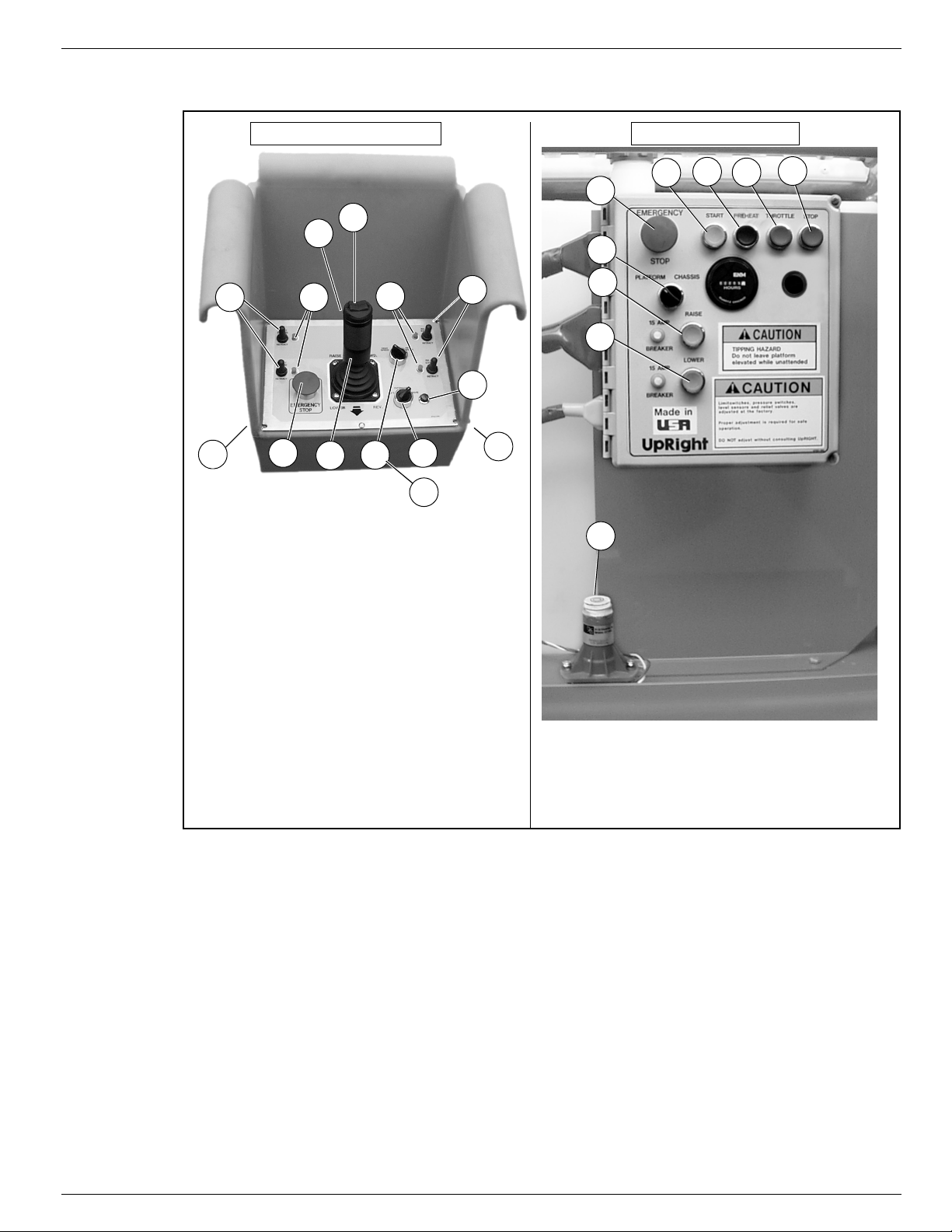
Commandes et indicateurs 067903-025 LX31/LX41/LX50
4*
2
1
3
7**
9
10
8
Options de stabilisateurs
* Les commutateurs et témoins de stabilisateurs ne sont
installés que sur les machines équipées de stabilisateurs.
** La sélection de stabilisateur n’est offerte que sur les
machines équipées de stabilisateurs.
5*
5*
4*
1. Commutateur de direction
2. Bouton de verrouillage du levier
3. Levier de commande
4. Commutateurs de stabilisateurs
5. Témoins de stabilisateurs
6. Bouton d’arrêt d’urgence
7. Sélecteur de levage/conduite
8. Sélecteur de vitesse/couple
9. Témoin d’activation de conduite
10. Contacteur à clé
11. Bouton de préchauffage
12. Bouton d’avertisseur
6
11
1. Arrêt d’urgence
2. Sélecteur de
plate-forme/châssis
3. Bouton d’élévation
4. Bouton d’abaissement
5. Bouton de démarrage
6. Bouton de préchauffage
7. Bouton d’accélérateur
8. Bouton d’arrêt
9. Capteur de niveau
7
1
2
3
4
5
6
8
9
Commandes de la plate-forme Commandes du châssis
12
C
OMMANDES
ET INDICATEURS
Figure 16 :
Commandes et indicateurs
Guide de l’opérateur Page 5
Page 30
067903-025 LX31/LX41/LX50 Inspection de sécurité avant utilisation
ATTENTION
!
!
AVERTISSEMENT
!
!
I
NSPECTION
DE SÉCURITÉ
AVANT
UTILISATION
NOTA :
Lire d’abord attentivement toutes les règles de sécurité, le mode d’emploi, les étiquettes et les règles
nationales de sécurité. Chaque jour avant d’utiliser la machine :
1. Ouvrir les panneaux des modules et rechercher tout dommage, fuite de fluide ou pièce manquante.
2. Vérifier le niveau indiqué par la jauge du réservoir de fluide hydraulique avec la plate-forme
complètement abaissée. Faire l’appoint si nécessaire.
3. S’assurer que le niveau d’électrolyte de toutes les batteries est correct (voir « Entretien des batteries »
à la page 38).
4. Vérifier les niveaux d’huile moteur et de carburant.
5. Vérifier que les garde-corps sont en place, que l’extension coulissante de la plate-forme est bloquée
avec l’axe et que toute la boulonnerie est correctement serrée.
6. Vérifier la pression des pneus : 3,4 bar (
7. Examiner soigneusement l’ensemble la plate-forme élévatrice pour s’assurer qu’elle ne présente pas
de dommages tels que soudures ou éléments structurels fêlés, pièces desserrées ou manquantes,
fuites de fluide, câbles ou flexibles endommagés, connexions desserrées ou pneus endommagés.
8. Lorsque le moteur est froid, vérifier le niveau du liquide de refroidissement.
NE PAS vérifier le niveau de liquide de refroidissement lorsque le moteur ou le radiateur est chaud, car
le liquide bouillant pourrait causer des brûlures graves.
50 psi
).
E
SSAI DE FONCTIONNEMENT
SE TENIR ÉLOIGNÉ
Avant d’utiliser la plate-forme, vérifier que la surface de la zone de travail ne présente pas de dangers tels
que des trous, des dénivellations, des bosses ou des débris.
Vérifier dans TOUTES les directions, y compris au-dessus de la plate-forme élévatrice, qu’il n’y a ni
obstruction ni conducteur électrique.
Protéger le câble du pupitre de commande de tout dommage éventuel pendant la réalisation des
contrôles.
1. Au besoin, déplacer la machine jusqu’à un endroit dégagé afin de pouvoir l’élever complètement.
2. Mettre les boutons d’arrêt d’urgence du châssis et de la plate-forme en position ACTIVÉE (figure 2) en
les tirant.
3. Vérifier que le sélecteur plate-forme/châssis est en position plate-forme (PLATFORM).
4. Tourner le contacteur à clé de la plate-forme vers la droite jusqu’à la position de marche (ON). Tourner
la clé à fond vers la droite pour lancer le moteur et la relâcher dès que le moteur a démarré.
NOTA :
Si le moteur est froid, appuyer sur le bouton de préchauffage et le maintenir enfoncé pendant 6 secondes pour
chauffer les bougies.
DES SYSTÈMES
de la plate-forme élévatrice lorsqu
’
on réalise les contrôles suivants.
5. Mettre le sélecteur de levage/conduite en position de conduite (DRIVE). Le témoin d’activation de
conduite doit être ALLUMÉ.
6. Le sélecteur de levage/vitesse étant d’abord placé sur couple élevé (HIGH TORQUE) puis sur haute
vitesse (HIGH SPEED), appuyer sur le bouton de verrouillage du levier et pousser le levier de
commande sur les positions marche avant (FORWARD) puis marche arrière (REVERSE) pour vérifier
la vitesse et la commande directionnelle. La vitesse de déplacement de la machine augmentera à
mesure que le levier de commande est éloigné du point mort.
7. Appuyer sur le bouton de verrouillage du levier et pousser le commutateur de direction vers la DROITE,
puis vers la GAUCHE pour vérifier le fonctionnement de la direction.
Page 6 Guide de l’opérateur
Page 31

Essai de fonctionnement des systèmes 067903-025 LX31/LX41/LX50
8. Machines équipées des stabilisateurs en option :
a. Le sélecteur de levage/stabilisateurs/conduite étant en position de conduite (DRIVE), appuyer sur
le bouton de verrouillage du levier de commande et mettre chacun des commutateurs de
stabilisateur en position d’extension (EXTEND).
• Les stabilisateurs doivent être désactivés. Si un stabilisateur se déploie au cours de ce test,
ARRÊTER
b. Mettre le sélecteur de conduite/stabilisateurs/levage en position stabilisateurs (OUTRIGGER).
c. Appuyer sur le bouton de verrouillage du levier de commande et mettre le commutateur de
chaque stabilisateur en position d’extension (EXTEND) pour déployer les quatre (4)
stabilisateurs.
• Vérifier que les témoins de stabilisateurs sont ALLUMÉS.
d. Appuyer sur le bouton de verrouillage du levier de commande et mettre le commutateur de
chaque stabilisateur en position de rétraction (RETRACT).
• Rétracter partiellement les quatre (4) stabilisateurs. Les témoins de stabilisateurs doivent
CLIGNOTER.
• Rétracter complètement les quatre (4) stabilisateurs. Les témoins de stabilisateurs doivent
s’ÉTEINDRE.
9. Ouvrir le module de commande pour accéder aux commandes du châssis et au capteur de niveau.
10. Régler le sélecteur de plate-forme/châssis à la position châssis (CHASSIS).
11. Enfoncer le bouton d’accélérateur. Appuyer sur le bouton d’élévation pour élever la plate-forme tout en
poussant le capteur de niveau pour l’écarter de la position horizontale. La plate-forme ne devrait s’élever
que partiellement et l’alarme d’inclinaison devrait retentir. Si la plate-forme continue à s’élever et/ou
qu’aucune alarme ne résonne,
réparée.
12. Relâcher le capteur de niveau et élever complètement la plate-forme.
13. Effectuer une inspection visuelle du dispositif d’élévation, du vérin d’élévation, des câbles et des tuyaux,
pour détecter tout dommage ou fonctionnement irrégulier. Vérifier qu’aucune pièce n’est lâche ou
manquante.
14. Abaisser partiellement la plate-forme au moyen du bouton d’abaissement, puis vérifier le
fonctionnement de l’alarme sonore d’abaissement.
15. Ouvrir la vanne d’abaissement d’urgence pour vérifier le fonctionnement (voir « Abaissement
d’urgence » à la page 33). Une fois la plate-forme complètement abaissée, relâcher le bouton pour
refermer la soupape.
16. Mettre le sélecteur de plate-forme/châssis en position plate-forme (PLATFORM).
17. Fermer et verrouiller les couvercles des modules.
18. Monter sur la plate-forme et s’assurer que le loquet du portillon est engagé.
19. Positionner le sélecteur de levage/conduite en position de levage (LIFT).
20. Appuyer sur le bouton de verrouillage du levier et amener progressivement le levier de commande en
position d’élévation (UP) pour élever la plate-forme. Ce faisant, actionner le levier sur toute sa course
afin de vérifier la vitesse d’élévation proportionnelle. Tirer lentement le levier de commande en position
d’abaissement (DOWN) pour faire descendre la plate-forme. S’assurer que l’alarme d’abaissement
retentit.
21. Machines équipées des stabilisateurs en option :
a. Le sélecteur de levage/stabilisateurs/conduite étant en position de levage (LIFT), appuyer sur le
bouton de verrouillage du levier de commande et mettre tous les commutateurs de stabilisateur
en position d’extension (EXTEND).
• Les stabilisateurs devraient être désactivés. Si un stabilisateur se déploie au cours de ce test,
ARRÊTER
22. Mettre le contacteur à clé du boîtier de commande en position d’arrêt (OFF), appuyer sur le bouton
d’arrêt d’urgence et descendre de la plate-forme.
. Retirer la machine du service jusqu’à ce qu’elle ait été réparée.
ARRÊTER
. Abaisser la plate-forme et la mettre hors service jusqu’à ce qu’elle ait été réparée.
et mettre la machine hors service jusqu’à ce qu’elle ait été
Guide de l’opérateur Page 7
Page 32

067903-025 LX31/LX41/LX50 Utilisation
AVERTISSEMENT
!
!
U
TILISATION
Avant
NOTA :
Ne jamais élever ou abaisser la plate-forme lorsque les freins de stationnement sont desserrés, ce qui
pourrait résulter en des dommages ou blessures graves.
D
ÉPLACEMENT
1. Vérifier que :
• le bouton d’arrêt d’urgence du châssis est en position ACTIVÉ (tiré);
• le témoin d’activation de conduite est ALLUMÉ;
• le sélecteur de plate-forme/châssis est sur la position plate-forme (PLATFORM).
d’utiliser la plate-forme élévatrice, s’assurer que les inspections de sécurité avant utilisation ont été
effectuées, que les problèmes éventuels ont été corrigés et que l’opérateur a reçu une formation adéquate
pour l’utilisation de cette machine.
AVEC
LA PLATE
-
FORME ABAISSÉE
NOTA :
NOTA :
Si le témoin d’activation de conduite est ÉTEINT, vérifier que la plate-forme est complètement abaissée et
que les stabilisateurs (si la machine en est équipée) sont complètement rétractés.
2. Une fois sur la plate-forme, fermer et verrouiller le portillon. Vérifier que les garde-corps sont en place
et proprement montés avec les pièces de fixation correctement serrées.
3. Vérifier que le parcours est exempt de toute personne, obstacle, trou et dénivellation, et que la route
peut supporter la charge des roues.
4. Vérifier les dégagements au-dessus, au-dessous et sur les côtés de la plate-forme.
5. Tirer le bouton d’arrêt d’urgence du boîtier de commande en position ACTIVÉ.
6. Tourner le contacteur à clé du boîtier de commande à fond vers la droite pour lancer le moteur et
relâcher la clé dès que le moteur a démarré.
Si le moteur est froid, appuyer sur le bouton de préchauffage et le maintenir enfoncé pendant 6 secondes
pour chauffer les bougies.
7. Mettre le sélecteur de levage/conduite en position de conduite (DRIVE).
8. Mettre le sélecteur de plage de vitesses sur couple élevé (HIGH TORQUE).
9. Saisir le levier de commande afin d’appuyer sur le bouton de verrouillage du levier (lorsque le bouton
de verrouillage du levier est relâché, l’alimentation électrique du boîtier de commande est coupée).
Pousser ou tirer lentement le levier de commande en marche avant (FORWARD) ou marche arrière
(REVERSE) pour se déplacer dans la direction souhaitée. Plus le levier est éloigné de la position
centrale (neutre), plus la machine se déplace rapidement.
10. Lors du déplacement, pousser sur le sélecteur de gamme de vitesse sur vitesse élevée (HIGH SPEED)
pour se déplacer sur surfaces planes ou sur couple élevé (HIGH TORQUE) pour gravir des côtes ou se
déplacer dans des espaces restreints.
Page 8 Guide de l’opérateur
Page 33

Utilisation 067903-025 LX31/LX41/LX50
D
ÉPLACEMENT
Se déplacer avec la plate-forme élevée
AVEC
LA PLATE
UNIQUEMENT
-
FORME ÉLEVÉE
sur des surfaces horizontales solides.
NOTA :
D
NOTA :
É
Lorsqu’elle est élevée, la plate-forme ne peut se déplacer qu’à vitesse réduite et seulement si les essieux
avant et arrière sont parallèles.
1. Vérifier que le parcours est exempt de toute personne, obstacle, trou et dénivellation, que le terrain est
plat et peut supporter la charge des roues.
2. Vérifier les dégagements au-dessus, au-dessous et sur les côtés de la plate-forme.
3. Mettre le sélecteur de levage/conduite en position de conduite (DRIVE).
4. Pousser le levier de commande en marche avant (FORWARD) ou marche arrière (REVERSE) pour se
déplacer dans la direction souhaitée.
5. Si la machine s’immobilise et l’alarme d’inclinaison résonne, abaisser immédiatement la plate-forme et
conduire la machine jusqu’à une surface plane avant d’élever à nouveau la plate-forme.
IRECTION
Pousser le commutateur de direction vers la
roues pour s’assurer qu’elles tournent dans la bonne direction.
La direction n’est pas à centrage automatique. Les roues doivent être remises en position droite à l’aide du
commutateur de direction.
LÉVATION
La machine doit se trouver sur une surface plane et ferme, capable d’en supporter le poids. Si la machine
est équipée de stabilisateurs, les utiliser pour la mettre de niveau [voir « Mise de niveau de la plate-forme
(machines équipées de stabilisateurs seulement) » à la page 32].
ET ABAISSEMENT
DROITE
ou la
GAUCHE
DE LA PLATE
pour orienter les roues. Observer les
-
FORME
1. Positionner le sélecteur de levage/conduite en position de levage (LIFT).
2. Tout en maintenant le levier de commande de sorte que le bouton de verrouillage du levier soit enfoncé,
pousser lentement le levier de commande vers le haut (UP) pour élever la plate-forme. Plus le levier est
poussé vers le haut, plus l’élévation est rapide.
3. Une fois le travail achevé, mettre le sélecteur de levage/conduite en position de levage (LIFT) et
abaisser la plate-forme en tirant le levier de commande en arrière jusqu’à ce que la plate-forme soit
complètement abaissée.
Guide de l’opérateur Page 9
Page 34

067903-025 LX31/LX41/LX50 Utilisation
AVERTISSEMENT
!
!
M
ISE DE NIVEAU
(
MACHINES
Si les stabilisateurs sont utilisés, ils doivent tous être fermement en contact avec le sol.
OMMUTATEURS ET TÉMOINS DE STABILISATEURS
C
Il y a un commutateur et un témoin pour chacun des stabilisateurs (voir figure 16).
Chacun des commutateurs permet d’abaisser ou de relever un stabilisateur.
Chaque témoin indique la position du stabilisateur.
• Lorsqu’un témoin est ÉTEINT, le stabilisateur correspondant est complètement rétracté.
• Lorsqu’un témoin CLIGNOTE, le stabilisateur correspondant est partiellement étendu.
• Lorsqu’un témoin est ALLUMÉ, le stabilisateur correspondant est fermement appuyé sur le sol.
ISE DE NIVEAU DE LA PLATE-FORME (EXTENSION DES STABILISATEURS
M
1. S’assurer que l’extension coulissante de la plate-forme est complètement
rétractée avant d’actionner les stabilisateurs.
2. Regarder autour de la machine, s’assurer que rien ne gène l’extension
des stabilisateurs et que la surface sur laquelle ils s’appuient peut
supporter le poids de la machine.
3. Mettre le sélecteur de levage/stabilisateurs/conduite en position
stabilisateurs (OUTRIGGER).
4. Appuyer sur le bouton de verrouillage du levier de commande et actionner
les commutateurs des stabilisateurs pour les étendre, jusqu’à ce qu’ils
s’appuient fermement sur le sol.
5. Tout en observant le niveau à bulle du garde-corps, étendre le
stabilisateur se trouvant à l’opposé de la position de la bulle, jusqu’à ce
que la plate-forme soit de niveau. Par exemple, si la bulle se trouve à l’avant et sur la gauche de l’orbite,
étendre le stabilisateur arrière droit. Continuer d’ajuster les stabilisateurs jusqu’à ce que la bulle soit
centrée dans le petit cercle indiquant que la plate-forme est de niveau.
6. S’assurer que tous les stabilisateurs s’appuient fermement sur le sol. Les stabilisateurs sont fermement
appuyés sur le sol lorsque leurs témoins sont ALLUMÉS.
ÉQUIPÉES
DE LA PLATE
DE STABILISATEURS
-
FORME
Figure 17 :
SEULEMENT
)
)
Niveau orbital à bulle de la plate-forme
ÉTRACTION DES STABILISATEURS
R
1. Abaisser complètement la plate-forme.
2. Mettre le sélecteur de levage/stabilisateurs/conduite en position stabilisateurs (OUTRIGGER).
3. Appuyer sur le bouton de verrouillage du levier de commande et mettre le commutateur de chaque
stabilisateur en position de rétraction (RETRACT).
• Les témoins de stabilisateurs doivent être ÉTEINTS lorsque les stabilisateurs sont complètement
rétractés.
• Le témoin d’activation de conduite ne s’allume que si les quatre stabilisateurs sont complètement
rétractés.
Page 10 Guide de l’opérateur
Page 35

Utilisation 067903-025 LX31/LX41/LX50
A
BAISSEMENT
D’
URGENCE
LX31
1. Ouvrir la vanne d’abaissement d’urgence en tirant le
2. Une fois la plate-forme abaissée à fond, relâcher le
ET
LX41
Le bouton de commande d’abaissement d’urgence se
trouve à l’arrière de la machine, à la base du ciseau.
bouton et en le maintenant dans cette position.
bouton pour fermer la soupape.
LX50
Le commutateur d’abaissement d’urgence se trouve à l’arrière de
la machine, à la base du ciseau.
Figure 18 :
Figure 19 :
Vanne d’abaissement d’urgence, LX31 et LX41
Vanne d’abaissement d’urgence, (LX50)
1. Maintenir le commutateur enfoncé pour ouvrir la vanne
d’abaissement d’urgence.
2. Une fois la plate-forme complètement abaissée, relâcher le
commutateur pour refermer la vanne.
Guide de l’opérateur Page 11
Page 36

067903-025 LX31/LX41/LX50 Remorquage ou treuillage
ATTENTION
AVERTISSEMENT
!
!
R
EMORQUAGE
N’effectuer les opérations suivantes que si la machine est immobilisée et qu’il est nécessaire de la
déplacer, ou pour la hisser sur une remorque à l’aide d’un treuil, pour le transport (voir « Transport de la
plate-forme élévatrice » à la page 36).
NE PAS remorquer ou treuiller la machine à plus de 0,3 m/s (1 pi/s). Une vitesse plus élevée causerait
des dommages au train motopropulseur et entraînerait l’annulation de la garantie.
D
ESSERRAGE
Ne jamais élever ou abaisser la plate-forme lorsque les
freins de stationnement sont desserrés, ce qui pourrait
résulter en des dommages ou blessures graves.
Ne jamais desserrer les freins si la machine est sur
une pente.
Caler les roues avant de desserrer le frein de
stationnement.
Accrocher la machine au véhicule remorqueur avant
de desserrer les freins.
OU TREUILLAGE
DE FREIN
DE STATIONNEMENT
Figure 20 :
Pompe de desserrage de frein de stationnement
A
PRÈS
1. Fermer la vanne à pointeau en tournant le bouton vers la droite.
2. Actionner la pompe de desserrage de frein jusqu’à ce que le frein de stationnement se desserre et que
les roues puissent être tournées.
3. La machine va maintenant rouler lorsqu’on la pousse ou qu’on la tire.
4. S’assurer que la vanne à pointeau est ouverte et vérifier que les freins de stationnement sont engagés
avant d’utiliser la machine.
UTILISATION
1. Abaisser complètement la plate-forme.
2. Stationner la machine sur une surface plane, de préférence à l’abri des vandales et protégée des
enfants et de toute personne qui pourrait éventuellement s’en servir sans autorisation.
3. Tourner le contacteur à clé sur la position d’arrêt (OFF), puis retirer la clé afin d’empêcher l’utilisation
non autorisée.
,
TOUS
LES JOURS
Page 12 Guide de l’opérateur
Page 37

Garde-corps rabattables 067903-025 LX31/LX41/LX50
AVERTISSEMENT
!
!
G
ARDE
-
CORPS
Cette procédure n’est valable que pour le passage entre des portes. Il faut remettre les garde-corps en
position correcte avant d’utiliser la machine.
RABATTABLES
Figure 21 :
Garde-corps rabattables
R
EPLI DES
GARDE
NOTA :
1. Placer le boîtier de commande sur la
2. En commençant par l’extension
• retirer les écrous, boulons et
• retirer les écrous, boulons et
• retirer les écrous, boulons et
• rabattre les garde-corps latéraux sur l’extension coulissante de la plate-forme;
• laisser le garde-corps d’extrémité relevé et rentrer complètement l’extension coulissante.
3. Passer à l’arrière de la plate-forme :
• fermer et verrouiller le portillon arrière;
• retirer les écrous, boulons, rondelles et cornières du garde-corps arrière;
• rabattre le garde-corps arrière sur la plate-forme en veillant à garder le portillon verrouillé.
4. Déverrouiller le portillon latéral, de façon à pouvoir rabattre les garde-corps latéraux en deux sections
5. Rabattre la moitié arrière des garde-corps latéraux sur la plate-forme :
• soulever les garde-corps latéraux pour les rabattre sur la plate-forme, par-dessus le garde-corps
6. Rabattre la moitié avant des garde-corps latéraux sur la plate-forme :
• soulever les garde-corps pour les rabattre sur l’extension coulissante, de façon à ce que leurs
7. Soulever et rabattre le garde-corps d’extension coulissante avant.
-
Garder toutes les pièces de fixation
lorsque vous effectuez les procédures
suivantes.
plate-forme.
coulissante :
rondelles des coins supérieurs
avant des garde-corps (A);
rondelles du rail intermédiaire
latéral de l’extension
coulissante (B);
rondelles des douilles de retenue
des garde-corps de l’extension coulissante sur la plate-forme (C);
séparées. Retirer également les écrous, boulons et rondelles du garde-corps droit, à l’opposé du
verrouillage de portillon, afin de pouvoir les séparer également en deux sections (E).
arrière.
montants s’engagent dans les découpes de la plinthe (F) de l’extension.
CORPS
A
B
C
F
D
E
P
ROCÉDURE
1. Relever le garde-corps avant et le pousser vers les bas pour l’assujettir en position verticale.
2. Relever les garde-corps latéraux et les pousser vers les bas pour les assujettir en position verticale, puis
aligner les trous et installer les boulons, rondelles et écrous. Serrer fermement.
3. Relever l’un des garde-corps d’extension coulissante latéraux, aligner les trous et installer les boulons,
rondelles et écrous. Serrer fermement. Répéter l’opération pour l’autre garde-corps latéral de
l’extension coulissante.
4. Relever le garde-corps arrière et installer les cornières, écrous, boulons et rondelles.
5. Suspendre le boîtier de commande au garde-corps avant.
6. Avant d’utiliser la plate-forme élévatrice, vérifier que toute la boulonnerie est bien en place et
correctement serrée.
Avant d’utiliser la machine, les garde-corps doivent être fermement assujettis et en position correcte.
Guide de l’opérateur Page 13
DE MISE EN PLACE
Page 38

067903-025 LX31/LX41/LX50 Transport de la plate-forme élévatrice
ATTENTION
T
RANSPORT
P
L
1. Abaisser complètement la plate-forme.
2. Débrancher le câble négatif (-) de la borne de la batterie.
3. Attacher le boîtier de commande au garde-corps avant.
4. Attacher le mécanisme de commande d’élévation au châssis.
EVAGE PAR GRUE
1. N’accrocher les sangles que sur les
2. Placer la plate-forme sur le véhicule de
3. Caler les roues.
4. Arrimer la plate-forme élévatrice sur le
DE LA PLATE
RÉPARATION
anneaux d’arrimage/levage du châssis.
transport, en position de transport.
véhicule de transport à l’aide de chaînes et
sangles d’une capacité de charge adéquate
attachées aux anneaux d’arrimage/levage
du châssis.
POUR
-
FORME
L’
EXPÉDITION
ÉLÉVATRICE
Vue de derrière
Figure 22 :
Anneaux d’arrimage/levage
Transport de la plate-forme
Vue de devant
C
ONDUITE
OU TREUILLAGE
SUR UN CAMION
OU
UNE REMORQUE
NOTA :
Ne pas treuiller à plus de 0,3 m/s
1. Monter la machine sur le camion ou la remorque.
A. Pour
B. Pour
2. Arrimer la plate-forme élévatrice sur le véhicule de transport à l’aide de chaînes et sangles d’une
capacité de charge adéquate attachées aux anneaux d’arrimage/levage du châssis.
Un serrage excessif des chaînes ou des sangles dans les anneaux d’arrimage/levage peut
endommager la plate-forme élévatrice.
conduire
a. conduire la machine jusqu’à la rampe et la mettre en position de transport;
b. redresser les roues et arrêter le moteur de la machine;
c. caler les roues.
treuiller
a. conduire la machine jusqu’à la rampe;
b. accrocher le câble du treuil sur les anneaux d’arrimage/levage;
c. desserrer les freins de stationnement (voir « Remorquage ou treuillage » à la page 34);
d. treuiller la plate-forme en position de transport;
e. caler les roues.
la machine sur le véhicule de transport :
la machine sur le véhicule de transport :
(1 pi/s)
.
Page 14 Guide de l’opérateur
Page 39

Entretien 067903-025 LX31/LX41/LX50
AVERTISSEMENT
!
!
Pivot central du
ciseau inférieur
Barre de
blocage
Axe de
verrouillage
Pivot central du
ciseau supérieur
E
NTRETIEN
B
LOCAGE
Ne jamais travailler sur le système d’élévation de la plate-forme
élévatrice lorsque celle-ci est en position élevée, sans l’avoir
d’abord bloqué.
NE PAS se tenir à proximité du système d’élévation pendant le
déploiement ou le repli de la barre de blocage.
DU SYSTÈME
D’
ÉLÉVATION
Figure 23 :
Blocage du système d’élévation
NSTALLATION
I
1. Garer la plate-forme élévatrice sur une surface plane et ferme.
2. Vérifier que le bouton d’arrêt d’urgence de la plate-forme est en
position ENGAGÉ.
3. Régler le sélecteur de plate-forme/châssis à la position châssis
(CHASSIS).
4. Démarrer le moteur au moyen des commandes du châssis.
5. Appuyer sur le bouton d’accélérateur. Le bouton restera enfoncé et le régime moteur augmentera. Au
moyen du bouton d’élévation, élever la plate-forme jusqu’à ce que la barre de blocage du ciseau puisse
être mise à la verticale.
6. Du côté gauche de la machine, désengager l’axe de verrouillage de la barre. Tourner la barre de
blocage du ciseau vers la gauche jusqu’à ce qu’elle soit à la verticale, entre les deux pivots centraux du
ciseau.
7. Appuyer sur le bouton d’abaissement et faire descendre la plate-forme jusqu’à ce qu’elle soit soutenue
par la barre de verrouillage.
8. Débrayer le moteur en appuyant sur le bouton de commande des gaz. Le bouton se rétracte et le
moteur se met au ralenti.
ETRAIT DE LA BARRE DE BLOCAGE
R
1. Au moyen des commandes du châssis, élever graduellement la plate-forme jusqu’à ce que la barre de
blocage du ciseau passe les deux pivots centraux du ciseau.
2. Tourner la barre de blocage du ciseau vers la droite jusqu’à ce que l’axe de verrouillage s’engage.
3. Appuyer sur le bouton d’abaissement pour abaisser complètement la plate-forme.
4. Vérifier que le bouton d’accélérateur est désengagé et que le sélecteur plate-forme/châssis est en
position plate-forme (PLATFORM).
DE LA
BARRE DE BLOCAGE
Guide de l’opérateur Page 15
Page 40

067903-025 LX31/LX41/LX50 Entretien
AVERTISSEMENT
!
!
2
1
1. Voyant de niveau
2. Bouchon de remplissage
F
LUIDE
Le réservoir de fluide hydraulique se trouve dans le module de
puissance.
HYDRAULIQUE
Figure 24 :
Réservoir de fluide hydraulique
NOTA :
E
Ne jamais faire l’appoint de fluide lorsque la plate-forme est élevée.
1. S’assurer que la plate-forme est complètement abaissée.
2. Vérifier le niveau de fluide au voyant.
3. Retirer le bouchon de remplissage et faire l’appoint avec le fluide
approprié.
NTRETIEN
Risque d’émanations gazeuses explosives. Tenir les batteries à
l’écart de toute source d’étincelles, flammes et articles de fumeur.
Ne jamais manipuler les batteries sans porter de lunettes de
sécurité.
L’électrolyte (liquide de la batterie) est un liquide très corrosif.
Enlever en rinçant soigneusement à l’eau claire tout liquide
renversé.
Toujours remplacer les batteries par des batteries UpRight ou d’un
modèle agréé par le constructeur.
DES BATTERIES
Figure 25 :
Emplacement de la batterie
Vérifier le niveau d’électrolyte chaque semaine, particulièrement si
la plate-forme élévatrice est utilisée en climat chaud et sec.
Si le niveau d’électrolyte ne recouvre pas les plaques de batterie
d’au moins 10 mm (
SEULEMENT. Ne pas utiliser l’eau du robinet très calcaire; ce qui
réduirait la durée de vie des batteries.
La batterie et les câbles doivent être inspectés régulièrement pour
détecter tout signe de fissures du boîtier de la batterie, de fuite d’électrolyte et de corrosion des bornes.
Inspecter les câbles pour détecter taches d’usure, ruptures dans l’isolation et bornes de câbles cassées.
Voir le Manuel d’entretien pour des instructions détaillées et la prolongation de la vie utile des batteries.
0,375 po
), ajouter de l’eau distillée
Page 16 Guide de l’opérateur
Page 41

Entretien 067903-025 LX31/LX41/LX50
ATTENTION
!
!
M
OTEUR
Moteur
1
IQUIDE DE REFROIDISSEMENT
L
Le vase d’expansion est monté à
l’intérieur de la porte du module de
puissance.
1. Retirer le bouchon du vase
d’expansion.
2. Ajouter du liquide de refroidissement
jusqu’au repère plein (FULL).
Figure 26 :
4
3
NOTA :
H
C
Ne jamais retirer le bouchon du
radiateur lorsque le moteur est chaud.
UILE
Le moteur
vérification et de l’appoint d’huile.
Consulter le Manuel d’entretien pour le
remplacement du filtre à huile.
1. Retirer la jauge d’huile et vérifier le
niveau.
2. Si le niveau est insuffisant, retirer le bouchon de remplissage.
3. Faire l’appoint avec l’huile moteur appropriée (voir le Manuel d’entretien du moteur fourni avec la
machine).
NE PAS vérifier le niveau de liquide de refroidissement lorsque le moteur ou le radiateur est chaud,
car le liquide bouillant pourrait causer des brûlures graves.
ARBURANT
Le réservoir de carburant se trouve dans le module de commande, derrière les
commandes du châssis. Ce réservoir est translucide. Vérifier le niveau de
carburant dans le réservoir.
doit être arrêté
lors de la
1. Bouchon du radiateur
2. Vase d’expansion du liquide
de refroidissement
3. Bouchon du réservoir d’huile
4. Jauge d’huile
2
Figure 27 :
Niveau de carburant
Guide de l’opérateur Page 17
Page 42
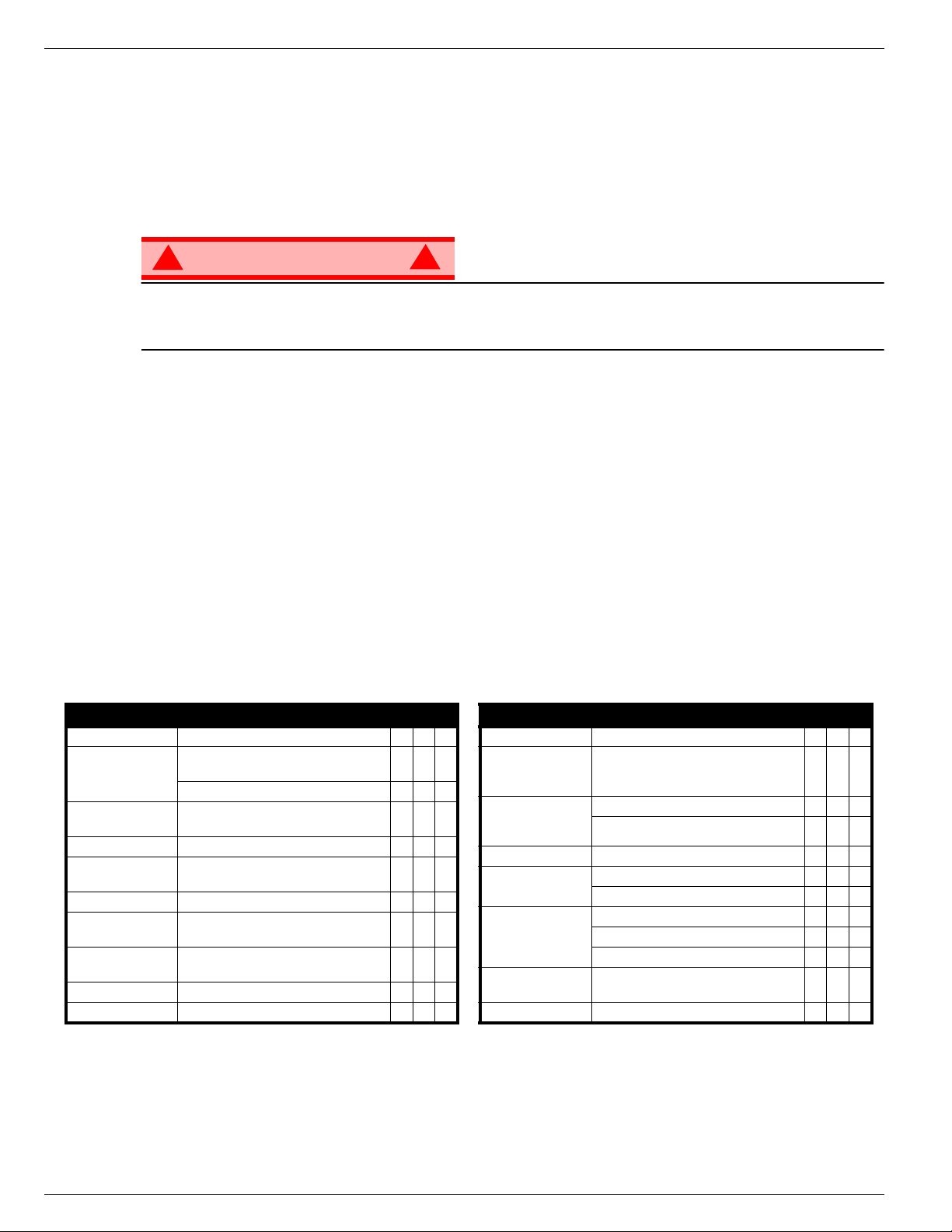
067903-025 LX31/LX41/LX50 Programme d’entretien préventif
AVERTISSEMENT
!
!
P
ROGRAMME
D’
ENTRETIEN
PRÉVENTIF
Une inspection complète comprend les examens visuels et contrôles de fonctionnement périodiques,
ainsi que tous les réglages nécessaires au bon fonctionnement. Les inspections visuelles quotidiennes
évitent une usure anormale et prolongent la vie utile de tous les systèmes. Les opérations prescrites dans
les programmes d’inspection et d’entretien doivent être effectuées à intervalles réguliers. Les inspections
et entretiens doivent être effectuées par un personnel compétent et familiarisé avec les procédures
mécaniques et électriques.
Avant tout entretien préventif, se familiariser avec le fonctionnement de la machine.
Toujours bloquer le système élévateur s’il est nécessaire de se trouver dans la zone du ciseau lorsque
la plate-forme est élevée (voir page 37).
Le tableau d’entretien préventif quotidien est conçu pour les entretiens et réparations de la machine.
Photocopier la liste de contrôle d’entretien préventif quotidien et utiliser le tableau comme guide pour
l’inspection avant utilisation de la machine.
L
ISTE DE CONTRÔLE
ÉGENDE DU TABLEAU D’ENTRETIEN
L
D’
ENTRETIEN
PRÉVENTIF
APPORT D’ENTRETIEN
R
QUOTIDIEN
\
O = Oui/acceptable
N = Non/non acceptable
R = Réparé/acceptable
COMPOSANT VÉRIFICATION OU ENTRETIEN À EFFECTUER O N R
Batterie Vérifier le niveau d’électrolyte.
Vérifier que les tuyaux flexibles ne sont pas
Châssis
Câble de commande
Commandes Vérifier le fonctionnement des commutateurs.
Moteurs
Dispositif d’élévation Vérifier si la structure présente des fissures.
Vanne d'abaissement
d’urgence
Ensemble de la
machine
Fluide hydraulique Vérifier le niveau.
Pompe hydraulique Vérifier s’il y a des fuites aux raccords.
pincés et n'ont pas de point de frottement.
Vérifier si les soudures sont fissurées.
Vérifier l’extérieur du câble et rechercher tout
pincement, pliure ou usure.
Vérifier le fonctionnement et s’assurer de
l’absence de fuites.
Faire fonctionner la vanne d'abaissement
d'urgence et vérifier son bon fonctionnement.
Contrôler tout dommage dû à une collision
et le réparer.
Date : ______________________________________
Propriétaire : _________________________________
o
N
de modèle : _______________________________
o
de série : _________________________________
N
Nom du technicien : ___________________________
COMPOSANT VÉRIFICATION OU ENTRETIEN À EFFECTUER O N R
Circuit hydraulique Vérifier s’il y a des fuites.
Autocollants
Extension et gardecorps de la plateforme
Pneus et roues Vérifier le bon état.
Huile et filtre moteur
Circuit carburant
Liquide de
refroidissement
Moyeux moteurs Vérifier s’il y a des fuites.
Vérifier que les autocollants ne sont pas
décollés, manquants ou illisibles.
Remplacer au besoin.
Vérifier si les soudures sont fissurées.
Vérifier l’état de la plate-forme.
Vérifier le niveau et l’état.
Vérifier s’il y a des fuites.
Vérifier le niveau de carburant.
Vérifier s’il y a des fuites.
Vérifier le filtre à air.
Vérifier le niveau (moteur froid).
Page 18 Guide de l’opérateur
Page 43

Programme d’entretien préventif 067903-025 LX31/LX41/LX50
NNNN
OOOOTTTTEEEESSSS
::::
Guide de l’opérateur Page 19
Page 44

067903-025 LX31/LX41/LX50 Autocollants
A
UTOCOLLANTS
Ces autocollants doivent être en place et en bon état pour utiliser la plate-forme. Lire, veiller à bien
comprendre et respecter les instructions des autocollants lors de l’utilisation de la plate-forme.
2
010076-301
LX31/LX41:
40
066558-301
LX50:
40
005223-908
060197-000
4
067480-300
13
LX31/LX41:
22
066562-300
LX50:
22
066562-303
5
061205-303
6
030768-002
7
064936-099
9
066552-300
ARRET
D URGENCE
11
067642-311
(Outrigger Units:
067642-304)
13
067480-301
(Outrigger Units)
USAGE DE LA PLATE-FORME ÉLÉVATRICE : Cette plate-forme élévatrice est destinée au levage de toute personne, de son
outillage et des matériaux utilisés sur le chantier. Elle est conçue pour les travaux de réparations et d'assemblage sur les points
élevés (plafonds, grues, charpentes de toit, immeubles, etc.). Tout autre usage de la plate-for me élévatrice est interdit !
CETTE PLATE-FORME ÉLÉVATRICE N'EST PAS ISOLÉE ! C'est pourquoi il est impératif de rester à distance sûre des lignes et
équipements électriques sous tension !
Il est interdit de dépasser la charge maximum admissible. Lisez le manuel de l'operateur pour plus de details.
Il est interdit d'utiliser la plate-forme comme appareil de levage ou grue !
NE JAMAIS dépasser la force manuelle autorisée pour cette machine. Lisez le manuel de l'operateur pour plus de details.
RÉPARTIR uniformément toutes les charges placées sur la plate-forme.
NE JAMAIS utiliser la machine sans avoir d'abord vérifié si la zone de travail est exempte de dangers tels que des trous,
dénivellations, bosses, trottoirs ou débris; et les éviter.
N'UTILISER la machine que sur des surfaces pouvant supporter la charge des roues.
NE JAMAIS utiliser la machine lorsque la vitesse du vent dépasse les spécifications pour la machine. Lisez le manuel de l'operateur
pour plus de details.
EN CAS D'URGENCE, appuyer sur le bouton d'ARRÊT D'URGENCE pour désactiver toutes les fonctions.
SI L'ALARME RETENTIT lorsque la plate-forme est élevée, ARRÊTER, abaisser la plate-forme avec précaution. Conduire la machine
jusqu'à une surface plane et ferme.
Il est interdit de monter ou de se tenir sur les garde-corps de la plate-forme et de passer de la plate-forme à un immeuble,
une structure préfabriquée, etc. !
Il est interdit de retirer le portillon, ou toute autre pièce de garde-corps ! Toujours vérifier que le portillon est fermé et verrouillé !
Il est interdit de maintenir le portillon en position ouverte lorsque la plate-forme est élevée !
Il est interdit d'accroître la hauteur ou la portée de la plate-forme au moyen d'échelles, échafaudages ou autres dispositifs similaires !
NE JAMAIS effectuer de travaux d'entretien sur la machine, si la plate-forme est en position élevée, sans tout d'abord bloquer le dispositif d'élévation.
INSPECTER minutieusement la machine en vue de soudures fissurées, de pièces de boulonnerie manquantes ou desserrées, de
fuites hydrauliques, de branchements électriques desserrés ou de câbles et flexibles endommagés avant d'utiliser la machine.
VÉRIFIER que tous les autocollants sont en place et lisibles avant d'utiliser la machine.
NE JAMAIS utiliser une machine qui est endommagée, qui ne fonctionne pas correctement ou dont les autocollants sont
manquants ou endommagés.
Il est interdit de mettre tout dispositif de sécurité hors service, ce qui mettrait en danger les personnes à bord de la
plate-forme et celles se trouvant dans la zone de travail.
NE JAMAIS charger les batteries à proximité d'étincelles ou d'une flamme vive. Lors de la charge, les batteries dégagent de
l'hydrogène, un gaz explosif.
Sauf autorisation de la part d'UpRight, toute modification de la plate-forme est interdite.
APRÈS AVOIR UTILISÉ la plate-forme élévatrice, mettre les contacteurs à clé en position d'arrêt , puis retirer la clé afin
d'empêcher l'utilisation non autorisée de la plate-forme.
067195-301
14
067478-300
15
027898-001
25
LX31: 066557-310
26
LX41: 066557-307
26
26
LX50: 066557-317
POUR UN DEMARRAGE MOTEUR
FROID, ALLUMEZ LES BOUGIES DE
PRECHAUFFAGE PENDANT 6 SEC.
067822-301
3434
066556-300
41
068639-300
42
43
066556-301
(Outrigger Units)
POUR UN DEMARRAGE MOTEUR
FROID, ALLUMEZ LES BOUGIES DE
PRECHAUFFAGE PENDANT 6 SEC.
067822-300
17
066551-301
44
TIPPING HAZARD
If horn sounds continuously
lower platform and relevel.
066551-003
45
38
067481-301
12
063423-300
21
066561-301
(Outrigger Units)
Page 20 Guide de l’opérateur
Page 45
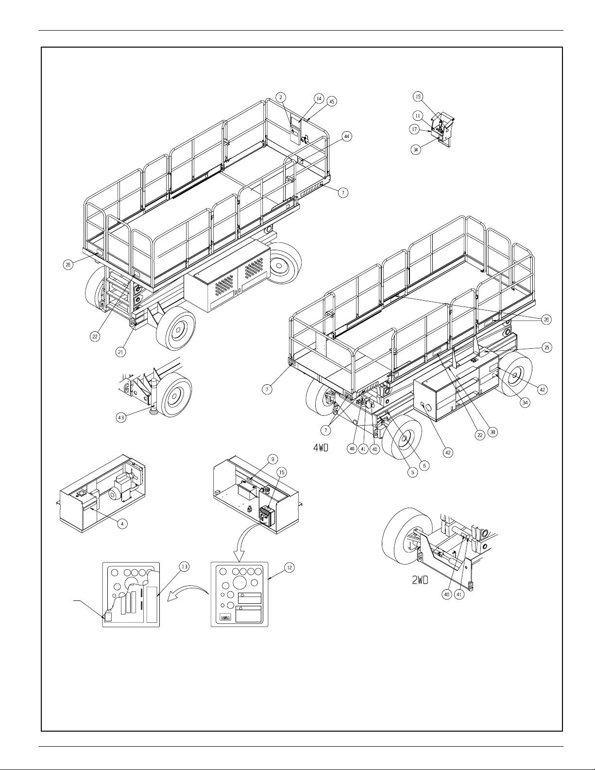
Autocollants 067903-025 LX31/LX41/LX50
Arrière
Figure 28 :
Emplacement des autocollants de sécurité
Commandes de la plate-forme
Module de puissance Module de commande
Intérieur
Commandes du châssis
Avant
Guide de l’opérateur Page 21
Page 46

067903-025 LX31/LX41/LX50 Caractéristiques
C
ARACTÉRISTIQUES
Ces caractéristiques peuvent être changées sans préavis. Consulter le Manuel d’entretien pour les informations concernant l’entretien et les réparations. Voir le détail des composants dans le manuel de pièces.
Les performances peuvent être réduites par temps très chaud ou en cas de service sévère. Conforme ou
supérieur aux règles nationales de sécurité.
Article LX31 LX41 LX50
Dimensions de la plate-forme (à l’intérieur des plinthes)
Standard
Extension coulissante déployée
Capacité maximum de la plate-forme
Standard
Avec option d’extension arrière
Sur l'extension
Nombre maximum de personnes
Standard
Avec option d’extension arrière
Hauteur
Hauteur de travail
Hauteur max. de la plate-forme
Hauteur min. de la plate-forme
Hauteur max. au déplacement
Dimensions
Poids, standard 2x2 :
Poids, plate-forme avec extension 2x4 :
Largeur hors tout
Hauteur hors tout, garde-corps relevés
Hauteur hors tout, garde-corps abaissés
Longueur hors tout, extension rétractée
Longueur hors tout, extension déployée
Vitesse au sol
Plate-forme abaissée
Plate-forme élevée
Tension du circuit électrique
Capacité du réservoir hydraulique
Pression max. du circuit hydraulique
Fluide hydraulique
Température normale : au-dessus 0 °C [32 °F]
Basse température : au-dessous 0 °C [32 °F]
Température extrême : au-dessous -17 °C [0 °F]
Système de levage
Vitesse de levage
Source d'énergie
Commande de déplacement
Leviers de commande
Déplacement horizontal
Pneus
Pression de gonflage des pneus
Freins de stationnement
Rayon de braquage (intérieur)
Pente franchissable
Empattement
Garde au sol
Garde-corps
Niveau sonore
4x4 :
4x4 :
2x2 :
4x4 :
2x2 :
4x4 :
2x4 :
4x4 :
3,96 m x 1,73 m [
4,83 m x 1,73 m [
11,45 m [
4645 kg [
4767 kg [
0 à 5,0 km/h [
0 à 0,48 km/h [
107 L [
207 bar [
Un vérin d’élévation à un étage Un vérin d’élévation à un étage Deux vérins d’élévation à un étage
Levage, 40 s/abaissement, 52 s Levage, 45 s/abaissement, 60 s Levage, 80 s/abaissement, 112 s
Diesel 20 hp Kubota, 3 cylindres,
Manche à balai muni d’un levier
d’enclenchement solidaire
2 roues, moteurs hyd.
4 roues, moteurs hyd.
8 plies NHS 10-16,5 8 plies NHS 10-16,5 8 plies NHS 10-16,5, remplis de poly
Double disque à serrage par ressort
et desserrage hydraulique
1,1 m [
rabattable avec portillon.
907 kg [
794 kg [
227 kg [
156 po x 68 po
190 po x 68 po
2000 lb
1750 lb
500 lb
] 3,96 m x 1,73 m [
] 4,83 m x 1,73 m [
] 680 kg [
] 567 kg [
] 227 kg [
156 po x 68 po
190 po x 68 po
1500 lb
1250 lb
500 lb
] 3,96 m x 1,73 m [
] 4,83 m x 1,73 m [
] 454 kg [
] 341 kg [
] 227 kg [
156 po x 68 po
190 po x 68 po
1000 lb
750 lb
500 lb
5 personnes 5 personnes 4 personnes
5 personnes 4 personnes 3 personnes
9,45 m [
1,43 m [
26 pi 3 po
8 m [
4314 kg [
4436 kg [
2,29 m [
2,53 m [
1,64 m [
4,02 m [
4,89 m [
37 pi 6 po
] 14,34 m [
31 pi
] 12,34 m [
56,3 po
] 1,66 m [
] 8 m [
9511 lb
]
9780 lb
]
10 241 lb
]
10 440 lb
]
90 po
] 2,29 m [
99,8 po
] 2,76 m [
64,5 po
] 1,87 m [
160 po
] 4,02 m [
192 po
] 4,89 m [
0 à 3,1 mi/h
0 à 0,5 mi/h
] 0 à 5,0 km/h [
] 0 à 0,48 km/h [
5026 kg [
5148 kg [
5357 kg [
5479 kg [
47 pi 3 po
40 pi 6 po
26 pi 3 po
11 080 lb
11 349 lb
11 810 lb
12 079 lb
] 17,1 m [
] 15,1 m [
65,3 po
] 1,9 m [
] 8 m [
]
]
]
]
90 po
] 2,29 m [
109 po
] 3 m [
73,5 po
] 2,1 m [
160 po
] 4,02 m [
192 po
] 4,89 m [
0 à 3,1 mi/h
0 à 0,5 mi/h
] 0 à 5,0 km/h [
] 0 à 0,48 km/h [
6242 kg [
6364 kg [
6460 kg [
6583 kg [
56 pi
49 pi 6 po
76 po
26 pi 3 po
13 761 lb
14 030 lb
14 242 lb
14 513 lb
90 po
118,3 po
82,5 po
160 po
192 po
0 à 3,1 mi/h
0 à 0,5 mi/h
12 V c.c. 12 V c.c. 12 V c.c.
28,3 gallons US
3000 psi
] 207 bar [
] 107 L [
28,3 gallons US
3000 psi
] 207 bar [
] 107 L [
28,3 gallons US
3000 psi
ISO no 46 ISO no 46 ISO no 46
ISO no 32 ISO no 32 ISO no 32
ISO no 15 ISO no 15 ISO no 15
refroidi par eau
Diesel 20 hp Kubota,
3 cylindres, refroidi par eau
Diesel ou hp Kubota,
3 cylindres, refroidi par eau
Proportionnelle Proportionnelle Proportionnelle
3,4 bar [
1,22 m [
17° [
19° [
2,9 m [
2,95 m [
0,24 m [
43,5 po
50 psi
] 3,4 bar [
Double disque à serrage par ressort
48 po
] 1,22 m [
30 %
]
35 %
]
114,5 po
]
116 po
]
9,5 po
] 0,24 m [
] de haut,
Manche à balai muni d’un levier
d’enclenchement solidaire
2 roues, moteurs hyd.
4 roues, moteurs hyd.
50 psi
]S.O.
et desserrage hydraulique
48 po
] 1,22 m [
30 %
17° [
19° [
2,9 m [
2,95 m [
1,1 m [
35 %
114,5 po
43,5 po
]
]
]
116 po
]
9,5 po
] 0,24 m [
] de haut,
rabattable avec portillon.
Manche à balai muni d’un levier
d’enclenchement solidaire
2 roues, moteurs hyd.
4 roues, moteurs hyd.
Double disque à serrage par ressort
et desserrage hydraulique
48 po
24 %
13,5° [
24 %
13,5° [
114,5 po
2,9 m [
116 po
2,95 m [
9,5 po
43,5 po
1,1 m [
rabattable avec portillon.
]
]
]
]
]
]
]
]
]
]
]
]
]
]
]
]
]
]
]
]
]
]
]
]
]
]
]
]
] de haut,
Page 22 Guide de l’opérateur
Page 47
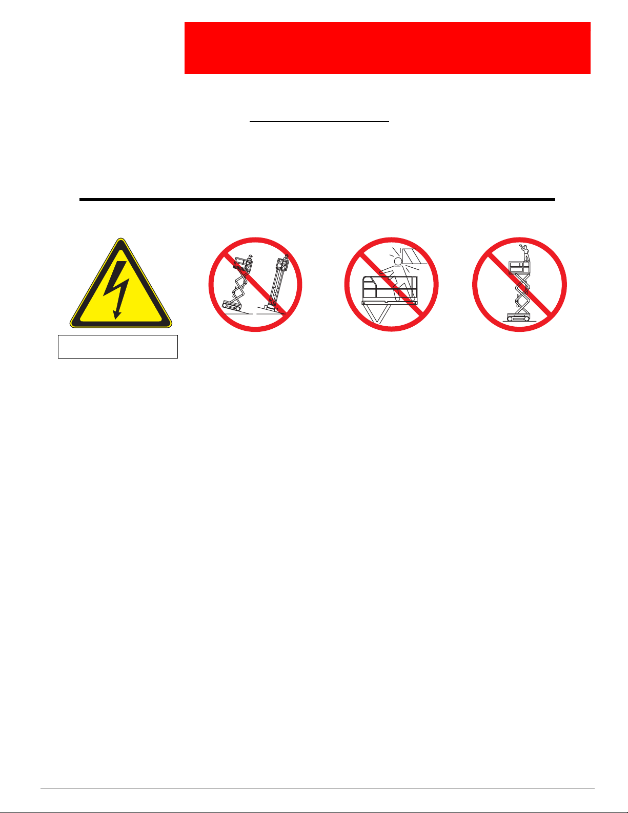
ETRIEBSANLEITUNG
B
WARNUNG
Alle Bediener müssen die Sicherheitsregeln und Betriebsanleitungen gründlich durchlesen,
verstehen und befolgen, bevor sie an irgendeiner UpRight-Hocharbeitsbühne Wartungsarbeiten
Sicherheitsregeln
Sicherheitsregeln
SicherheitsregelnSicherheitsregeln
Gefahr der Tötung
Gefahr der Tötung
Gefahr der Tötung Gefahr der Tötung
durch Stromschlag
durch Stromschlag
durch Stromschlagdurch Stromschlag
ausführen oder diese in Betrieb nehmen.
Gefahr des Umkippens
Gefahr des Umkippens Kollisionsgefahr
Gefahr des UmkippensGefahr des Umkippens
Kollisionsgefahr Absturzgefahr
KollisionsgefahrKollisionsgefahr
Absturzgefahr
AbsturzgefahrAbsturzgefahr
DIESE MASCHINE
IST NICHT ISOLIERT!
VERWENDUNG DER HOCHARBEITSBÜHNE:
die Arbeit benötigten Materials. Sie ist für die Ausführung von Reparatur- und Montagearbeiten an hochgelegenen Arbeitsplätzen (Decken,
Kränen, Dachkonstruktionen, Gebäuden usw.) vorgesehen. Sämtliche anderen Einsatzzwecke der Hocharbeitsbühne sind verboten!
DIESE HOCHARBEITSBÜHNE IST NICHT ISOLIERT!
Geräte einen Sicherheitsabstand einzuhalten!
Es ist verboten
Seite 48.
Die Verwendung bzw. der Betrieb der Hocharbeitsbühne als Hebevorrichtung oder Kran (Heben oder Absenken von Lasten)
Den vorgeschriebenen manuellen Kraftaufwand für diese Maschine
Einschränkungen“ auf Seite 48
Alle Lasten gleichmäßig auf der Arbeitsbühne
Maschine
Rinnsteiner Schutt zu untersuchen und diese zu umgehen.
Maschine nur auf Standflächen
Die Maschine
„Beaufort-Skala“ auf Seite 48
unter
BEI NOTFÄLLEN
FALLS
während des Hochfahrens der Arbeitsbühne ein
Maschine auf eine feste, waagerechte Standfläche bringen.
Es ist verboten
vorgefertigte Betonbauteile zu besteigen!
Der Abbau der Schwenktür oder anderer Teile des Geländers
sicher verriegelt ist!
Es ist verboten
Es ist verboten
An der Maschine
Maschine vor Benutzung gründlich auf gerissene Schweißnähte, lose oder fehlende Metallteile, Hydrauliklecks, lose Kabelanschlüsse und
beschädigte Kabel oder Schläuche
Vor Benutzung
Maschine
Die Außerkraftsetzung von Sicherheitseinrichtungen
Personen eine Gefahr dar.
Batterie
freigesetzt.
Modifikationen der Hocharbeitsbühne
Arbeitsbühne
abgezogen wird.
, die zulässige Höchstbelastung zu überschreiten! Weitere Anweisungen finden Sie unter „Besondere Einschränkungen“ auf
NIEMALS
NIEMALS
NIEMALS
in Betrieb nehmen, ohne zuvor das Arbeitsgelände auf Bodengefahren, wie z.B. Löcher, abschüssige Stellen, Unebenheiten,
NICHT
in Betrieb nehmen, wenn der Nennwert für die Windgeschwindigkeit überschritten wird. Weitere Anweisungen finden Sie
den NOTAUSSCHALTER drücken, um alle Antriebsfunktionen zu deaktivieren.
, das Geländer der Arbeitsbühne zu besteigen, auf diesem zu stehen oder von der Arbeitsbühne her Gebäude, Stahl- oder
, die Schwenktür offen zu lassen (mit Befestigungsbändern offen zu halten), wenn die Arbeitsbühne angehoben wird!
, die Höhe bzw. Reichweite der Arbeitsbühne durch Aufstellen von Leitern, Gerüsten oder ähnlichen Gegenständen zu vergrößern!
NIEMALS
SICHERSTELLEN
in der Nähe von Funken oder bei offener Flamme aufladen. Beim Laden von Batterien wird explosives Wasserstoffgas
NACH GEBRAUCH
Wartungsarbeiten durchführen, wenn die Arbeitsbühne hochgefahren ist, ohne das Hubgestell zu blockieren.
in Betrieb nehmen, wenn diese beschädigt ist, nicht einwandfrei funktioniert oder deren Schilder beschädigt sind oder fehlen.
NIEMALS
oder die Maschine mit ausgefahrener
Arbeitsbühne fahren, wenn der Boden
.
BETREIBEN
.
ÜBERPRÜFEN
, dass alle Schilder angebracht und gut lesbar sind.
sind verboten
vor unbefugter Benutzung sichern, indem beide Schlüsselschalter ausgeschaltet werden und der Schlüssel
die Arbeitsbühne ausfahren
nicht fest und eben ist.
Diese Hocharbeitsbühne dient zum Heben von Personen und deren Werkzeugen sowie des für
Aus diesem Grund ist es dringend erforderlich, von stromführenden Teilen elektrischer
NIE
VERTEILEN
, deren Tragfähigkeit für die Radlasten ausreicht.
.
WARNSIGNAL ERTÖNT
ist verboten!
.
ist verboten
bzw. nur mit Genehmigung von UpRight zulässig.
und stellt für die auf der Hocharbeitsbühne und in ihrer Reichweite befindlichen
Arbeitsbühne
fahren, ohne vorher sicherzustellen,
dass oberhalb der Maschine keine
Hindernisse oder sonstigen Gefahren
überschreiten. Weitere Anweisungen finden Sie unter
Es ist immer zu kontrollieren, ob die Schwenktür geschlossen und
NIEMALS
bestehen.
, sofort STOPPEN und die Arbeitsbühne vorsichtig absenken.
in Stellung
NIEMALS
Schutzgeländer oder dessen
mittlere Schiene steigen, darauf
stehen oder sitzen.
auf das
ist verboten!
„Besondere
Seite 1
Page 48

067903-025 LX31/LX41/LX50
I
NHALT
Einführung. . . . . . . . . . . . . . . . . . . . . . . . . . . . . . . . . . . . . . . . . . . . . . . . . . . . . . . . . . . . . . . . . . . . . . . . . .47
Allgemeine Beschreibung . . . . . . . . . . . . . . . . . . . . . . . . . . . . . . . . . . . . . . . . . . . . . . . . . . . . . . . . . . . . .47
Besondere Einschränkungen . . . . . . . . . . . . . . . . . . . . . . . . . . . . . . . . . . . . . . . . . . . . . . . . . . . . . . . . . .48
Alle Modelle. . . . . . . . . . . . . . . . . . . . . . . . . . . . . . . . . . . . . . . . . . . . . . . . . . . . . . . . . . . . . . . . . . . . . . . . . . . . . . . 48
Arbeitsbühnentragfähigkeit . . . . . . . . . . . . . . . . . . . . . . . . . . . . . . . . . . . . . . . . . . . . . . . . . . . . . . . . . . . . . . . . . . . 48
Manueller Kraftaufwand . . . . . . . . . . . . . . . . . . . . . . . . . . . . . . . . . . . . . . . . . . . . . . . . . . . . . . . . . . . . . . . . . . . . . 48
Beaufort-Skala. . . . . . . . . . . . . . . . . . . . . . . . . . . . . . . . . . . . . . . . . . . . . . . . . . . . . . . . . . . . . . . . . . . . . . . . . . . . . 48
Überlastungsalarm beim Heben . . . . . . . . . . . . . . . . . . . . . . . . . . . . . . . . . . . . . . . . . . . . . . . . . . . . . . . . . . . . . . . 48
Bedien- und Anzeigeelemente. . . . . . . . . . . . . . . . . . . . . . . . . . . . . . . . . . . . . . . . . . . . . . . . . . . . . . . . . .49
Sicherheitsinspektion vor Inbetriebnahme . . . . . . . . . . . . . . . . . . . . . . . . . . . . . . . . . . . . . . . . . . . . . . .50
Systemfunktionsprüfung . . . . . . . . . . . . . . . . . . . . . . . . . . . . . . . . . . . . . . . . . . . . . . . . . . . . . . . . . . . . . .50
Betrieb . . . . . . . . . . . . . . . . . . . . . . . . . . . . . . . . . . . . . . . . . . . . . . . . . . . . . . . . . . . . . . . . . . . . . . . . . . . . .52
Fahren mit gesenkter Arbeitsbühne . . . . . . . . . . . . . . . . . . . . . . . . . . . . . . . . . . . . . . . . . . . . . . . . . . . . . . . . . . . . 52
Fahren mit gehobener Arbeitsbühne. . . . . . . . . . . . . . . . . . . . . . . . . . . . . . . . . . . . . . . . . . . . . . . . . . . . . . . . . . . . 53
Lenken. . . . . . . . . . . . . . . . . . . . . . . . . . . . . . . . . . . . . . . . . . . . . . . . . . . . . . . . . . . . . . . . . . . . . . . . . . . . . . . . . . . 53
Anheben und Absenken der Arbeitsbühne . . . . . . . . . . . . . . . . . . . . . . . . . . . . . . . . . . . . . . . . . . . . . . . . . . . . . . . 53
Nivellieren der Arbeitsbühne
(nur bei Maschinen mit Hilfsstützen) . . . . . . . . . . . . . . . . . . . . . . . . . . . . . . . . . . . . . . . . . . . . . . . . . . . . . . . . . . . . 54
Hilfsstützenschalter und Anzeigeleuchten . . . . . . . . . . . . . . . . . . . . . . . . . . . . . . . . . . . . . . . . . . . . . . . . . . . . 54
Nivellieren der Arbeitsbühne (Hilfsstützen ausfahren) . . . . . . . . . . . . . . . . . . . . . . . . . . . . . . . . . . . . . . . . . . . 54
Einfahren der Hilfsstützen . . . . . . . . . . . . . . . . . . . . . . . . . . . . . . . . . . . . . . . . . . . . . . . . . . . . . . . . . . . . . . . . 54
Notabsenkung. . . . . . . . . . . . . . . . . . . . . . . . . . . . . . . . . . . . . . . . . . . . . . . . . . . . . . . . . . . . . . . . . . . . . . .55
LX31 und LX41 . . . . . . . . . . . . . . . . . . . . . . . . . . . . . . . . . . . . . . . . . . . . . . . . . . . . . . . . . . . . . . . . . . . . . . . . 55
LX50. . . . . . . . . . . . . . . . . . . . . . . . . . . . . . . . . . . . . . . . . . . . . . . . . . . . . . . . . . . . . . . . . . . . . . . . . . . . . . . . . 55
Schleppen oder Windenbetrieb. . . . . . . . . . . . . . . . . . . . . . . . . . . . . . . . . . . . . . . . . . . . . . . . . . . . . . . . .56
Freigabe der Feststellbremse . . . . . . . . . . . . . . . . . . . . . . . . . . . . . . . . . . . . . . . . . . . . . . . . . . . . . . . . . . . . . . . . . 56
Nach täglichem Gebrauch . . . . . . . . . . . . . . . . . . . . . . . . . . . . . . . . . . . . . . . . . . . . . . . . . . . . . . . . . . . . .56
Umklappen der Schutzgeländer . . . . . . . . . . . . . . . . . . . . . . . . . . . . . . . . . . . . . . . . . . . . . . . . . . . . . . . .57
Umklappen . . . . . . . . . . . . . . . . . . . . . . . . . . . . . . . . . . . . . . . . . . . . . . . . . . . . . . . . . . . . . . . . . . . . . . . . . . . . . . . 57
Aufrichten . . . . . . . . . . . . . . . . . . . . . . . . . . . . . . . . . . . . . . . . . . . . . . . . . . . . . . . . . . . . . . . . . . . . . . . . . . . . . . . . 57
Transport der Arbeitsbühne . . . . . . . . . . . . . . . . . . . . . . . . . . . . . . . . . . . . . . . . . . . . . . . . . . . . . . . . . . .58
Transportvorbereitungen . . . . . . . . . . . . . . . . . . . . . . . . . . . . . . . . . . . . . . . . . . . . . . . . . . . . . . . . . . . . . . . . . . . . . 58
Heben durch einen Kran . . . . . . . . . . . . . . . . . . . . . . . . . . . . . . . . . . . . . . . . . . . . . . . . . . . . . . . . . . . . . . . . . . . . . 58
Arbeitsbühne durch Fahren oder Ziehen mit einer Winde auf einen LKW oder Anhänger laden . . . . . . . . . . . . . . 58
Wartung . . . . . . . . . . . . . . . . . . . . . . . . . . . . . . . . . . . . . . . . . . . . . . . . . . . . . . . . . . . . . . . . . . . . . . . . . . . .59
Blockieren des Hubgestells . . . . . . . . . . . . . . . . . . . . . . . . . . . . . . . . . . . . . . . . . . . . . . . . . . . . . . . . . . . . . . . . . . 59
Einsetzen der Stütze . . . . . . . . . . . . . . . . . . . . . . . . . . . . . . . . . . . . . . . . . . . . . . . . . . . . . . . . . . . . . . . . . . . . 59
Entfernen der Stütze . . . . . . . . . . . . . . . . . . . . . . . . . . . . . . . . . . . . . . . . . . . . . . . . . . . . . . . . . . . . . . . . . . . . 59
Hydraulikflüssigkeit . . . . . . . . . . . . . . . . . . . . . . . . . . . . . . . . . . . . . . . . . . . . . . . . . . . . . . . . . . . . . . . . . . . . . . . . . 59
Batteriewartung . . . . . . . . . . . . . . . . . . . . . . . . . . . . . . . . . . . . . . . . . . . . . . . . . . . . . . . . . . . . . . . . . . . . . . . . . . . . 60
Motor . . . . . . . . . . . . . . . . . . . . . . . . . . . . . . . . . . . . . . . . . . . . . . . . . . . . . . . . . . . . . . . . . . . . . . . . . . . . . . . . . . . . 61
Kühlmittel . . . . . . . . . . . . . . . . . . . . . . . . . . . . . . . . . . . . . . . . . . . . . . . . . . . . . . . . . . . . . . . . . . . . . . . . . . . . . 61
Öl . . . . . . . . . . . . . . . . . . . . . . . . . . . . . . . . . . . . . . . . . . . . . . . . . . . . . . . . . . . . . . . . . . . . . . . . . . . . . . . . . . . 61
Kraftstoff. . . . . . . . . . . . . . . . . . . . . . . . . . . . . . . . . . . . . . . . . . . . . . . . . . . . . . . . . . . . . . . . . . . . . . . . . . . . . . 61
Plan für vorbeugende Wartung . . . . . . . . . . . . . . . . . . . . . . . . . . . . . . . . . . . . . . . . . . . . . . . . . . . . . . . . .62
Kontrollliste zur täglichen vorbeugenden Wartung . . . . . . . . . . . . . . . . . . . . . . . . . . . . . . . . . . . . . . . . . . . . . . . . . 62
Wartungslegende. . . . . . . . . . . . . . . . . . . . . . . . . . . . . . . . . . . . . . . . . . . . . . . . . . . . . . . . . . . . . . . . . . . . . . . 62
Wartungsprotokoll . . . . . . . . . . . . . . . . . . . . . . . . . . . . . . . . . . . . . . . . . . . . . . . . . . . . . . . . . . . . . . . . . . . . . . 62
Schilder . . . . . . . . . . . . . . . . . . . . . . . . . . . . . . . . . . . . . . . . . . . . . . . . . . . . . . . . . . . . . . . . . . . . . . . . . . . .64
Technische Daten . . . . . . . . . . . . . . . . . . . . . . . . . . . . . . . . . . . . . . . . . . . . . . . . . . . . . . . . . . . . . . . . . . . .66
Seite 2 Betriebsanleitung
Page 49

Einführung 067903-025 LX31/LX41/LX50
WARNUNG
!
!
E
INFÜHRUNG
Dieses Handbuch beschreibt die Bedienung der Modelle LX 31, LX 41 und LX 50, bei denen die Arbeitsbühne
einen eingebauten Verbrennungsmotor hat. Dieses Handbuch muss ständig an der Maschine aufbewahrt
werden.
A
LLGEMEINE
B
ESCHREIBUNG
Abbildung 29:
1. Arbeitsbühne
Die Arbeitsbühne hat einen verstärkten
Stahlboden, ein Schutzgeländer mit
Mittelstrebe, Fußbleche und eine Zugangstür
am Heck und an beiden Seiten der
Arbeitsbühne. Die Schutzgeländer können
umgeklappt werden, um die Arbeitsbühne zu
betreten und zu transportieren.
2. Ausziehdeck
Die Arbeitsbühne
ordnungsgemäß zusammengesetzt und
angebrachte Schutzgeländer benutzen.
3. Arbeitsbühnen-Steuerpult
Das Arbeitsbühnene-Steuerpult enthält die
Bedienelemente zur Steuerung der Maschine.
Das Steurerpult sollte am vorderen, linken
oder techten Schutzgeländer hängen.
4. Handbuchfach
5. Hubgestell
Die Arbeitsbühne wird durch ein Hubgestell
angehoben oder abgesenkt. Dieses
Hubgestell ist ein Scherengestänge mit fünf
Teilen, dass durch zwei einstufige Hubzylinder
angetrieben wird.
6. Scherenschutz
7. Steuermodul
Im Steuermodul befindet sich der
Kraftstoffbehälter, der Hydraulikblock, das
Horn/der Alarm, die Batterie und das
Steuerpult des Fahrwerks.
8. Stromversorgung
Das Aggregat enthält den Motor, die Hydraulikpumpe und den Hydraulikbehälter.
9. Fahrwerk
Das Fahrwerk ist ein Gitterrahmen, der alle Bestandteile der Arbeitsbühne trägt.
10. Hilfsstützen (optional)
NICHT
ohne
1
10
2
9
Arbeitsbühnenmodelle der LX-Serie
3
4
2
10
8
6
10
7
5
10
Betriebsanleitung Seite 3
Page 50

067903-025 LX31/LX41/LX50 Besondere Einschränkungen
GAFAHR
! !
GAFAHR
! !
GAFAHR
! !
GAFAHR
! !
B
ESONDERE
A
A
LLE
Die Hochfahrfunktion ist NUR zu benutzen, wenn die Arbeitsbühne horizontal und auf festem Boden steht.
Die Arbeitsbühne darf NICHT über unebenes Gelände oder über Boden mit unzureichender Festigkeit
gefahren werden.
RBEITSBÜHNENTRAGFÄHIGKEIT
Die Tragfähigkeit bzw. zulässige Personenzahl der Arbeitsbühne NICHT überschreiten.
E
INSCHRÄNKUNGEN
M
ODELLE
Mit hochgefahrener Arbeitsbühne nur in Kriechgeschwindigkeit fahren.
Hochfahren der Arbeitsbühne ist nur auf ebenem, festem Boden zulässig.
Die maximale Tragfähigkeit der MASCHINE, inklusive Personen, ist je nach Modell und Ausstattung
verschieden. Siehe Abschnitt
„Technische Daten“ auf Seite 66
.
M
ANUELLER
Der manuelle Kraftaufwand ist die Kraft, die die Personen auf Objekte, wie Wände oder andere Konstruktionen,
außerhalb der Arbeitsbühne ausüben.
Der maximal zulässige manuelle Kraftaufwand ist auf 200 N (45 lbs.) pro Person und insgesamt auf maximal
400 N (90 lbs.) für zwei oder mehr Personen begrenzt.
Den maximalen Kraftaufwand dieser Maschine NICHT überschreiten.
B
EAUFORT
Die Maschine NIEMALS in Betrieb nehmen, wenn die Windgeschwindigkeit 45 km/h (28 mph) oder Windstärke
6 nach Beaufort-Skala überschreitet.
BEAUFORTNENNWERT
3 3,4~5,4 12,25~19,4 11,5~17,75 7,5~12,0
4 5,4~8,0 19,4~28,8 17,75~26,25 12,0~18
5 8,0~10,8 28,8~38,9 26,25~35,5 18~24,25
6 10,8~13,9 38,9~50,0 35,5~45,5 24,5~31
7 13,9~17,2 50,0~61,9 45,5~56,5 31,0~38,5
m/s km/h ft/s mph
Ü
BERLASTUNGSALARM
Alle Modelle sind mit einem Alarm ausgestattet, der den Bediener bei Überlastung der Arbeitsbühne warnt.
Wenn der Alarm während des Hebens erklingt, die Arbeitsbühne absenken und die Last verringern.
WINDGESCHWINDIGKEIT
-S
K
RAFTAUFWAND
KALA
FAHRBAHNBEDINGUNGEN
Papier und dünne Zweige bewegen sich, Fahnen wehen.
Staub und Papier werden aufgewirbelt, kleine Äste bewegen sich.
Büsche mit Blättern fangen an zu schwanken. Wellenbildung auf Wasseroberflächen.
Äste bewegen sich. Stromleitungen pfeifen. Regenschirm lässt sich schwer öffnen.
Bäume schwanken. Schwierigkeiten beim Laufen gegen den Wind.
BEIM
H
EBEN
Die Maschine nicht bedienen, wenn die Last der Arbeitsbühne die zulässige Tragkraft überschreitet.
Seite 4 Betriebsanleitung
Page 51

Bedien- und Anzeigeelemente 067903-025 LX31/LX41/LX50
4*
2
1
3
7**
9
10
8
Hilfsstützen-Optionen
* Hilfsstützenschalter und Hilfsstützenlampen befinden sich
nur an Mascshinen, die mit Hilfsstützen ausgestattet sind.
** Eine Auswahl der Hilfsstützen ist nur bei Maschinen
möglich, die mit Hilfsstützen ausgestattet sind.
5*
5*
4*
1. Lenkungsschalter
2. Sperrhebelschalter
3. Steuerhebel
4. Hilfsstützenschalter
5. Hilfsstützen-Anzeigeleuchten
6. Notausschalter
7. Heben/Fahren-Schalter
8. Geschwindigkeits-/Drehmoment-Wahlschalter
9. Fahrfunktionsleuchte
10. Schlüsselschalter
11. Vorglühknopf
12. Signalhorn
6
11
1. Notaus
2. Arbeitsbühne/Fahrwerk-
Schalter
3. Hochfahrknopf
4. Absenkknopf
5. Startknopf
6. Vorglühknopf
7. Drosselklappenknopf
8. Abstellknopf
9. Niveausensor
7
1
2
3
4
5
6
8
9
Bedienelemente der Arbeitsbühne Steuerpult des Fahrwerks
12
B
EDIEN
-
UND
A
NZEIGEELEMENTE
Abbildung 30:
Bedien- und Anzeigeelemente
Betriebsanleitung Seite 5
Page 52

067903-025 LX31/LX41/LX50 Sicherheitsinspektion vor Inbetriebnahme
ACHTUNG
!
!
WARNUNG
!
!
S
ICHERHEITSINSPEKTION
VOR
I
NBETRIEBNAHME
ANMERKUNG:
Sicherheitsanweisungen/-anforderungen sind gründlich durchzulesen und müssen verstanden und befolgt werden.
Täglich vor Inbetriebnahme die nachstehenden Schritte durchführen.
1. Module öffnen und auf Beschädigung, Flüssigkeitslecks und fehlende Teile prüfen.
2. Hydraulikflüssigkeitstand am Schauglas des Hydrauliktanks bei völlig abgesenkter Arbeitsbühne prüfen. Bei
Bedarf Flüssigkeit nachfüllen.
3. Nachprüfen, ob der Batterieflüssigkeitsstand stimmt (siehe „Batteriewartung“ auf Seite 60).
4. Füllstand von Motoröl und Kraftstoff überprüfen.
5. Nachprüfen, ob alle Schutzgeländer angebracht sind, die Deckverlängerung durch den Bolzen gesichert ist
und alle Befestigungselemente vorschriftsmäßig angezogen sind.
6. Reifendruck prüfen: 3,4 bar (50 psi)
7. Die gesamte Arbeitsbühne gründlich auf Schäden, wie z.B. gerissene Schweißnähte oder Strukturteile, lose
oder fehlende Teile, Flüssigkeitslecks, beschädigte Kabel und Schläuche, lose Anschlüsse und beschädigte
Reifen untersuchen.
8. Bei kaltem Motor den Füllstand des Motorkühlmittels prüfen.
Kühlmittel NICHT bei heißem Motor oder Kühler prüfen, da heißes Kühlmittel schwere Verbrennungen
verursachen kann.
S
YSTEMFUNKTIONSPRÜFUNG
Sämtliche Sicherheitsvorschriften, Bedienungsanleitungen, Bezeichnungsschilder sowie geltende
Bei Durchführung der nachstehenden Prüfungen ist von der Arbeitsbühne
Vor Inbetriebnahme der Arbeitsbühne den Arbeitsbereich auf Fahrbahn-Gefahrenstellen, wie z.B. Löcher,
Abhänge, Unebenheiten und Abfall untersuchen.
GESAMTE
Die
Leitungen überprüfen.
Bei den Überprüfungen das Steuerpultkabel gegen mögliche Beschädigung schützen.
1. Maschine, wenn erforderlich, an eine freie Stelle bringen, die das vollständige Hochfahren ermöglicht.
2. Die Notausschalter für Fahrwerk und Arbeitsbühne in die EIN Position ziehen (Abbildung 30).
3. Sicherstellen, dass der Arbeitsbühne/Fahrwerk-Schalter auf „Arbeitsbühne“ (PLATFORM) steht.
4. Den Zündschlüssel zur Arbeitsbühnensteuerung nach rechts auf EIN drehen. Zum Starten des Motors den
Schlüssel ganz nach rechts drehen; loslassen, sobald der Motor anspringt.
ANMERKUNG:
5. Heben/Fahren-Schalter auf „Fahren“ (DRIVE) stellen. Die Fahrfunktionsleuchte sollte EINGESCHALTET
sein.
6. Sperrhebelschalter zunächst bei Gangwähl-Schalterstellung auf „Hohes Drehmoment“ (HIGH TORQUE),
und danach auf „Hohe Drehzahl“ (HIGH SPEED), drücken und den Steuerhebel langsam erst auf „Vor wärts“
(FORWARD), dann auf „Rückwärts“ (REVERSE) stellen, um die Funktion der Geschwindigkeits- und
Richtungssteuerung zu prüfen. Je weiter der Steuerknüppel gedrückt bzw. gezogen wird, desto schneller
fährt die Maschine.
7. Den Sperrhebelschalter herunterdrücken und den Lenkschalter nach RECHTS dann nach LINKS drücken,
um die Lenkfunktion zu prüfen.
Umgebung, einschließlich oberhalb der Arbeitsbühne, auf Hindernisse und elektrische
Bei kaltem Motor den Vorglühknopf sechs Sekunden lang drücken, um die Glühkerzen vorzuwärmen.
ABSTAND ZU HALTEN
.
Seite 6 Betriebsanleitung
Page 53

Systemfunktionsprüfung 067903-025 LX31/LX41/LX50
8. Maschinen mit zusätzlichen Hilfsstützen:
a. Mit dem Schalter Fahren/Hilfsstützen/Heben in der Position „Fahren“ (DRIVE) den Sperrhebelschalter
am Steuerhebel herunterdrücken und jeden Hilfsstützenschalter in die Position „Ausfahren“ (EXTEND)
bringen.
• Die Hilfsstützen müssen außer Betrieb sein. Sollte irgendeine Hilfsstütze bei diesem Test ausfahren,
STOPPEN. Die Maschine erst wieder nach Reparatur benutzen.
b. Den Schalter Fahren/Hilfsstützen/Heben auf „Hilfsstützen“ (OUTRIGGER) stellen.
c. Den Sperrhebelschalter am Steuerhebel drücken und die einzelnen Hilfsstützenschalter auf
„Ausfahren“ (EXTEND) stellen, um alle vier (4) Hilfsstützen auszufahren.
•Überprüfen, ob die Hilfsstützen-Anzeigeleuchten EINGESCHALTET sind.
d. Den Sperrhebelschalter am Steuerhebel herunterdrücken und jeden Hilfsstützenschalter in die
Position „Einfahren“ (RETRACT) bringen.
• Alle vier (4) Hilfestützen teilweise einfahren. Die Hilfsstützen-Anzeigeleuchten müssen BLINKEN.
• Alle vier (4) Hilfestützen vollständig einfahren. Die Hilfsstützen-Anzeigeleuchten müssen
AUSGESCHALTET sein.
9. Steuermoduldeckel öffnen, um Zugang zum Steuerpult des Fahrwerks und zum Niveausensor zu erhalten.
10. Den Schalter Arbeitsbühne/Fahrwerk auf „Fahrwerk“ (CHASSIS) drehen.
11. Den Drosselklappenknopf eindrücken. Während der Niveausensor aus der Horizontalen gebracht wird, den
Hochfahrknopf drücken, um die Arbeitsbühne anzuheben. Die Arbeitsbühne darf sich nur teilweise heben,
und die Kippwarnung muß ertönen. Falls sich die Arbeitsbühne weiter anhebt bzw. keine Warnung ertönt,
STOPPEN und die Maschine so lange aus dem Betrieb ziehen, bis diese repariert ist.
12. Den Niveausensor loslassen und die Arbeitsbühne ganz ausfahren.
13. Hubgestell, Hubzylinder, Kabel und Schläuche visuell auf Beschädigungen und ruckhafte Bewegungen
untersuchen. Gerät auf fehlende oder lose Teile untersuchen.
14. Arbeitsbühne durch Hineindrücken des Absenkknopfes zum Teil absenken und die Funktion der akustischen
Senkwarnung prüfen.
15. Das Notsenkventil des Fahrwerks öffnen und auf ordnungsgemäßen Betrieb überprüfen (siehe
„Notabsenkung“ auf Seite 55). Ventil nach völligem Absenken der Arbeitsbühne durch Loslassen des Knopfes
schließen.
16. Den Schalter Arbeitsbühne/Fahrwerk auf „Arbeitsbühne“ (PLATFORM) stellen.
17. Moduldeckel schließen und sichern.
18. Arbeitsbühne betreten und sicherstellen, daß die Tür eingeklinkt ist.
19. Heben/Fahren-Schalter auf „Heben“ (LIFT) stellen.
20. Sperrhebelschalter drücken und den Steuerhebel allmählich auf „Nach oben“ (UP) schieben, um die
Arbeitsbühne hochzufahren; Steuerhebel ganz betätigen, um die proportionale Hubgeschwindigkeit zu
prüfen. Um die Arbeitsbühne abzusenken, den Bedienhebel langsam „Nach unten“ (DOWN) ziehen.
Nachprüfen, ob die Senkwarnung ertönt.
21. Maschinen mit zusätzlichen Hilfsstützen:
a. Während sich der Schalter Fahren/Hilfsstützen/Heben in der Position „Heben“ (LIFT) befindet, den
Sperrhebelschalter am Steuerhebel herunterdrücken und jeden Hilfsstützenschalter in die Position
„Ausfahren“ (EXTEND) bringen.
• Die Hilfsstützen müssen außer Betrieb sein. Sollte irgendeine Hilfsstütze bei diesem Test ausfahren,
STOPPEN. Arbeitsbühne absenken und Maschine aus dem Betrieb ziehen, bis sie repariert ist.
22. Schlüsselschalter des Steuergeräts auf AUS drehen, Notaustaster drücken und die Arbeitsbühne verlassen.
Betriebsanleitung Seite 7
Page 54

067903-025 LX31/LX41/LX50 Betrieb
WARNUNG
!
!
B
ETRIEB
ANMERKUNG:
durchgeführt wurde, etwaige Mängel behoben sind und der Bediener an dieser Maschine gründlich ausgebildet ist.
Arbeitsbühne niemals bei gelöster Feststellbremse in Betrieb nehmen. Schwere Verletzungen oder
Schäden können die Folge sein.
F
AHREN
1. Folgendes überprüfen:
• Der Notaustaster des Fahrwerks steht in der herausgezogenen Position EIN.
• Die Fahrfunktionsleuchte ist EINGESCHALTET.
• Der Arbeitsbühne/Fahrwerk-Schalter steht auf „Arbeitsbühne“ (PLATFORM).
ANMERKUNG:
Hilfsstützen (falls vorhanden) müssen voll eingefahren sein.
2. Nach dem Befestigen der Arbeitsbühne die Tür schließen und verriegeln. Nachprüfen, ob die
Schutzgeländer angebracht und einwandfrei montiert sind, wobei die Befestigungselemente
vorschriftsmäßig angezogen sein müssen.
3. Prüfen Sie nach, ob die Fahrstrecke von Personen, Hindernissen, Löchern und Abhängen frei ist und die
Radlasten aufnehmen kann.
4. Prüfen Sie nach, ob oberhalb, unterhalb und seitlich der Arbeitsbühne ein Sicherheitsabstand besteht.
5. Notaustaster des Steuergeräts auf Position EIN herausziehen.
6. Steuergerät-Schlüsselschalter zum Starten des Motors ganz nach rechts drehen; Schlüssel loslassen,
sobald der Motor anspringt.
Vor Inbetriebnahme der Arbeitsbühne ist sicherzustellen, dass die Sicherheitsinspektion vor Inbetriebnahme
MIT GESENKTER
Wenn die Fahrfunktionsleuchte AUSGESCHALTET ist, muss die Arbeitsbühne voll abgesenkt sein und die
A
RBEITSBÜHNE
ANMERKUNG:
7. Den Schalter Heben/Fahren auf „Fahren“ (DRIVE) stellen.
8. Den Gangwählschalter auf „Hohes Drehmoment“ (HIGH TORQUE) stellen.
9. Sperrhebelschalter so greifen, dass der Sperrhebel gedrückt ist (Loslassen des Sperrhebelschalter
unterbricht die Stromzufuhr zum Steuergerät). Den Steuerhebel langsam auf „Vorwärts“ (FORWARD) oder
„Rückwärts“ (REVERSE) schieben bzw. ziehen, um in die gewünschte Richtung zu fahren. Je weiter der
Steuerhebel aus der Mittelstellung gedrückt oder gezogen wird, desto schneller fährt die Maschine.
10. Während der Fahrt auf ebener Fahrbahn den Gangwahlschalter auf „Schnellgang“ (HIGH SPEED) schieben,
an Steigungen oder engen Stellen jedoch auf „Hohes Drehmoment“ (HIGH TORQUE).
Bei kaltem Motor den Vorglühknopf sechs Sekunden lang drücken, um die Glühkerzen vorzuwärmen.
Seite 8 Betriebsanleitung
Page 55

Betrieb 067903-025 LX31/LX41/LX50
F
AHREN
Mit gehobener Arbeitsbühne NUR auf festem, ebenem Boden fahren.
MIT GEHOBENER
A
RBEITSBÜHNE
ANMERKUNG:
Hinterachse parallel zueinander stehen.
1. Nachprüfen, ob die Fahrstrecke von Personen, Hindernissen, Löchern und Abhängen frei ist und die
Radlasten aufnehmen kann.
2. Nachprüfen, ob oberhalb, unterhalb und seitlich der Arbeitsbühne ein Sicherheitsabstand besteht.
3. Heben/Fahren-Schalter auf „Fahren“ (DRIVE) stellen.
4. Drücken Sie den Steuerhebel auf „Vorwärts“ (FORWARD) oder „Rückwärts“ (REVERSE), um in die
gewünschte Richtung zu fahren.
5. Falls die Maschine stehen bleibt und die Kippwarnung ertönt, die Arbeitsbühne sofort absenken und die
Maschine an eine ebene Stelle bringen, bevor die Arbeitsbühne wieder hochgefahren wird.
L
ENKEN
Zum Einschlagen der Räder den Lenkschalter nach RECHTS oder LINKS schieben. Beim Manövrieren die
Räder beobachten, um die Fahrtrichtung nachzuprüfen.
ANMERKUNG:
Geradeausstellung gebracht werden.
A
NHEBEN UND
Die Maschine muss auf festem, ebenem Boden stehen, der das Gewicht der Maschine hält. Die Maschine durch
zusätzliche Hilfsstützen (falls vorhanden) nivellieren (siehe -+).
1. Heben/Fahren-Schalter auf „Heben“ (LIFT) stellen.
2. Während man den Steuerhebel so fasst, dass der Sperrhebelschalter gedrückt ist, schiebt man den
Steuerhebel langsam auf „Nach oben“ (UP), um die Arbeitsbühne hochzufahren. Je weiter der Steuerhebel
gedrückt wird, desto höher wird die Hubgeschwindigkeit.
3. Nach beendeter Arbeit den Heben/Fahren-Schalter auf „Heben“ (LIFT) stellen und die Arbeitsbühne durch
Zurückziehen des Steuerhebels absenken, bis die Arbeitsbühne vollständig abgesenkt ist.
Die Arbeitsbühne lässt sich zwar in hochgefahrener Stellung langsam verfahren, jedoch nur, wenn Vorder- und
Die Lenkung ist nicht selbstrückstellend. Die Räder müssen durch Betätigen des Lenkschalters wieder in
A
BSENKEN
DER
A
RBEITSBÜHNE
Betriebsanleitung Seite 9
Page 56

067903-025 LX31/LX41/LX50 Betrieb
WARNUNG
!
!
N
IVELLIEREN
(
NUR BEI
Bei Einsatz der Hilfsstützen müssen alle vier (4) Hilfsstützen festen Bodenkontakt haben.
M
DER
ASCHINEN
A
RBEITSBÜHNE
MIT
H
ILFSSTÜTZEN
)
ILFSSTÜTZENSCHALTER UND
H
Jede Hilfsstütze hat einen Hilfsstützenschalter und eine Hilfsstützen-Anzeigeleuchte (siehe Abbildung 30).
Jeder Hilfsstützenschalter hebt und senkt eine Hilfsstütze.
Jede Hilfsstützen-Anzeigeleuchte zeigt die Position einer Hilfsstütze an.
• Wenn die Anzeigeleuchte AUSGESCHALTET ist, ist die Hilfsstütze völlig eingefahren.
• Wenn die Anzeigeleuchte BLINKT, ist die Hilfsstütze nur teilweise ausgefahren.
• Wenn die Anzeigeleuchte EINGESCHALTET ist, hat die Hilfsstütze festen Bodenkontakt.
IVELLIEREN DER ARBEITSBÜHNE
N
1. Bei Einsatz der Hilfsstützen muss das Ausziehdeck eingefahren sein.
2. Umgebung der Maschine überprüfen und sicherstellen, dass den Hilfsstützen
nichts im Wege steht und die darunterliegende Bodenfläche zur Aufnahme
des Maschinengewichts geeignet ist.
3. Den Schalter Heben/Hilfsstützen/Fahren auf „Hilfsstützen“ (OUTRIGGER)
stellen.
4. Sperrhebelschalter am Steuerhebel drücken und die Hilfsstützenschalter zum
Ausfahren der entsprechenden Hilfsstütze so lange betätigen, bis diese festen
Kontakt mit dem Boden hat.
5. Die Libellennivelliervorrichtung am Schutzgeländer beobachten. Die
Hilfsstütze, die sich entgegengesetzt zur Blase befindet, ausfahren, bis die
Arbeitsbühne gerade steht. Wenn z.B. die Luftblase in ihrer Kreisbahn vorn
links steht, die rechte hintere Hilfsstütze ausfahren. Justierung fortsetzen, bis die Blase in der Mitte des
kleineren Kreises steht und damit anzeigt, dass die Arbeitsbühne nivelliert ist.
6. Alle vier (4) Hilfsstützen müssen festen Bodenkontakt haben. Wenn die Anzeigeleuchten EINGESCHALTET
sind, haben alle Hilfsstützen festen Bodenkontakt.
NZEIGELEUCHTEN
A
ILFSSTÜTZEN AUSFAHREN
(H
Abbildung 31:
)
Libellennivelliervorrichtung
INFAHREN DER HILFSSTÜTZEN
E
1. Arbeitsbühne völlig absenken.
2. Den Schalter Heben/Hilfsstützen/Fahren auf „Hilfsstützen“ (OUTRIGGER) stellen.
3. Den Sperrhebelschalter am Steuerhebel herunterdrücken und jeden Hilfsstützenschalter in die Position
„Einfahren“ (RETRACT) bringen.
• Wenn die Hilfsstützen völlig eingefahren sind, sind die Hilfsstützen-Anzeigeleuchten AUSGESCHALTET.
• Die Fahrfunktionsleuchte geht erst an, wenn alle vier Hilfsstützen völlig eingefahren sind.
Seite 10 Betriebsanleitung
Page 57

Notabsenkung 067903-025 LX31/LX41/LX50
N
OTABSENKUNG
LX31
UND
LX41
Der Notabsenkknopf befindet sich am Heck der Maschine
am Fuß des Scherengestänges.
1. Das Notsenkventil wird durch Hochziehen und
Festhalten des Knopfs geöffnet.
2. Ventil nach völligem Absenken der Arbeitsbühne durch
Loslassen des Knopfes schließen.
LX50
Der Notsenkschalter befindet sich am Heck der Maschine am Fuß des
Scherengestells.
1. Notsenkventil durch Gedrückthalten des Schalters öffnen.
2. Ventil nach völligem Absenken der Arbeitsbühne durch Loslassen
des Schalters schließen.
Abbildung 32:
Abbildung 33:
Notsenkventil, LX31 und LX41
Notsenkventil, LX50
Betriebsanleitung Seite 11
Page 58
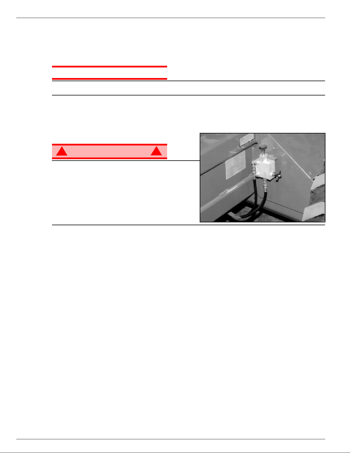
067903-025 LX31/LX41/LX50 Schleppen oder Windenbetrieb
ACHTUNG
WARNUNG
!
!
S
CHLEPPEN
ODER
Die folgenden Maßnahmen sind nur durchzuführen, wenn die Maschine nicht mit eigener Kraft fahren kann und
örtlich bewegt oder mit einer Winde vom Transportfahrzeug gezogen werden muss (siehe „Transport der
Arbeitsbühne“ auf Seite 58).
W
INDENBETRIEB
Die Maschine darf NICHT schneller als 0,3 m/s (
Geschwindigkeiten werden die Antriebsteile beschädigt und wird die Garantie hinfällig.
F
REIGABE
Arbeitsbühne niemals bei gelöster Feststellbremse in
Betrieb nehmen. Schwere Verletzungen oder Schäden
können die Folge sein.
Die Bremsen niemals lösen, wenn die Maschine auf einer
Böschung steht.
Die Räder mit Keilen sichern, bevor die Feststellbremse
gelöst wird.
Maschine vor Freigabe der Feststellbremse zum
Abschleppen anhängen.
1. Nadelventil durch Rechtsdrehung des Knopfes schließen.
2. Bremslösepumpe so lange betätigen, bis sich die Feststellbremse löst und die Räder drehen lassen.
3. Die Maschine lässt sich dann durch Schieben oder Ziehen rollen.
4. Vor Inbetriebnahme der Maschine unbedingt das Nadelventil öffnen und sicherstellen, dass die Bremsen im
Eingriff sind.
DER
F
ESTSTELLBREMSE
1 ft./s
) abgeschleppt werden. Bei höheren
Abbildung 34:
Freigabe der Feststellbremse
N
ACH TÄGLICHEM
1. Sicherstellen, dass die Arbeitsbühne vollständig abgesenkt ist.
2. Maschine auf ebenem Boden abstellen, vorzugsweise überdacht, und gegen mutwillige Beschädigung,
Eingriffe durch Kinder und unbefugte Inbetriebnahme sichern.
3. Schlüsselschalter auf AUS drehen und Schlüssel abziehen, um eine unbefugte Inbetriebnahme zu
verhindern.
Seite 12 Betriebsanleitung
G
EBRAUCH
Page 59

Umklappen der Schutzgeländer 067903-025 LX31/LX41/LX50
WARNUNG
!
!
U
MKLAPPEN
Diese Maßnahme ist nur beim Fahren durch Durchgänge zulässig. Schutzgeländer müssen vor Verwendung der
Maschine wieder in die vorgeschriebene Position gebracht werden.
DER
S
CHUTZGELÄNDER
Abbildung 35:
Umklappen der Schutzgeländer
U
MKLAPPEN
ANMERKUNG:
Durchführung der nachstehenden Schritte
sämtliche Befestigungen auf.
1. Steuergerät auf das Deck legen.
2. Am Ausziehdeck beginnen:
• Muttern, Schrauben und Unterleg-
• Muttern, Schrauben und Unterleg-
• Muttern, Schrauben und Unterleg-
• Die seitlichen Schutzgeländer auf dem Ausziehdeck herunterklappen.
• Das hintere Geländer stehen lassen und das Ausziehdeck einfahren.
3. Zum hinteren Teil der Arbeitsbühne gehen:
• Die hintere Tür schließen und verriegeln.
• Muttern, Schrauben, Unterlegscheiben und Eckenklammern von der Oberseite des hinteren Schutzgeländers
• Das hintere Schutzgeländer auf die Arbeitsbühne herunterklappen. Die Tür muss dabei verriegelt sein.
4. Die seitliche Tür entriegeln, so dass die linken seitlichen Schutzgeländer in zwei separaten Teilen heruntergeklappt werden können. Auch die Muttern, Schrauben und Unterlegscheiben gegenüber der Türverriegelung
am rechten seitlichen Schutzgeländer entfernen, so dass auch dieses Schutzgeländer in zwei Teile zerlegt
werden kann (E).
5. Die hintere Hälfte der seitlichen Schutzgeländer auf das Deck umklappen:
• Schutzgeländer anheben und umklappen, so dass sie auf den hinteren Schutzgeländern auf
6. Die vordere Hälfte der seitlichen Schutzgeländer auf die Arbeitsbühne umklappen:
• Schutzgeländer anheben und umklappen, so dass sie auf dem Ausziehdeck liegen. Dabei liegen die
7. Das vordere Schutzgeländer des Ausziehdecks anheben und umklappen.
Bewahren Sie bei der
scheiben von der oberen vorderen
Ecke des Schutzgeländers (A)
entfernen.
scheiben von der Mittelstrebe des
seitlichen Schutzgeländers am
Ausziehdeck (B) entfernen.
scheiben, die an den Oberseiten der
Sockel (C) angebracht sind und mit
denen die seitlichen Schutzgeländer
des Ausziehdecks befestigt sind, entfernen.
entfernen.
dem Deck liegen.
Pfosten des Geländers in den Durchbrüchen der Fußbleche des Ausziehdecks (F).
A
B
C
F
D
E
A
UFRICHTEN
1. Das vordere Schutzgeländer anheben und herunterdrücken, bis es einrastet, so dass das Geländer in seiner
vertikalen Stellung gesichert ist.
2. Die seitlichen Schutzgeländer anheben und jedes einzeln herunterdrücken bis es einrastet, so dass sie in
ihrer vertikalen Stellung gesichert sind. Die Löcher ausrichten und Schrauben, Unterlegscheiben und Muttern
anbringen. Fest anziehen.
3. Eines der seitlichen Schutzgeländer des Ausziehdecks anheben; Löcher ausrichten und Schrauben,
Unterlegscheiben und Muttern anbringen. Fest anziehen. Dasselbe gilt für die anderen seitlichen
Schutzgeländer des Ausziehdecks.
4. Das hintere Schutzgeländer anheben und die Eckenklammern, Muttern, Schrauben und Unterlegscheiben
anbringen.
5. Steuerpult am vorderen Schutzgitter einhängen.
6. Vor Inbetriebnahme der Arbeitsbühne ist nachzuprüfen, ob alle Befestigungselemente eingebaut und
vorschriftsmäßig angezogen sind.
Vor Inbetriebnahme der Maschine müssen die Schutzgeländer in der vorgeschriebenen Stellung sicher
befestigt sein.
Betriebsanleitung Seite 13
Page 60
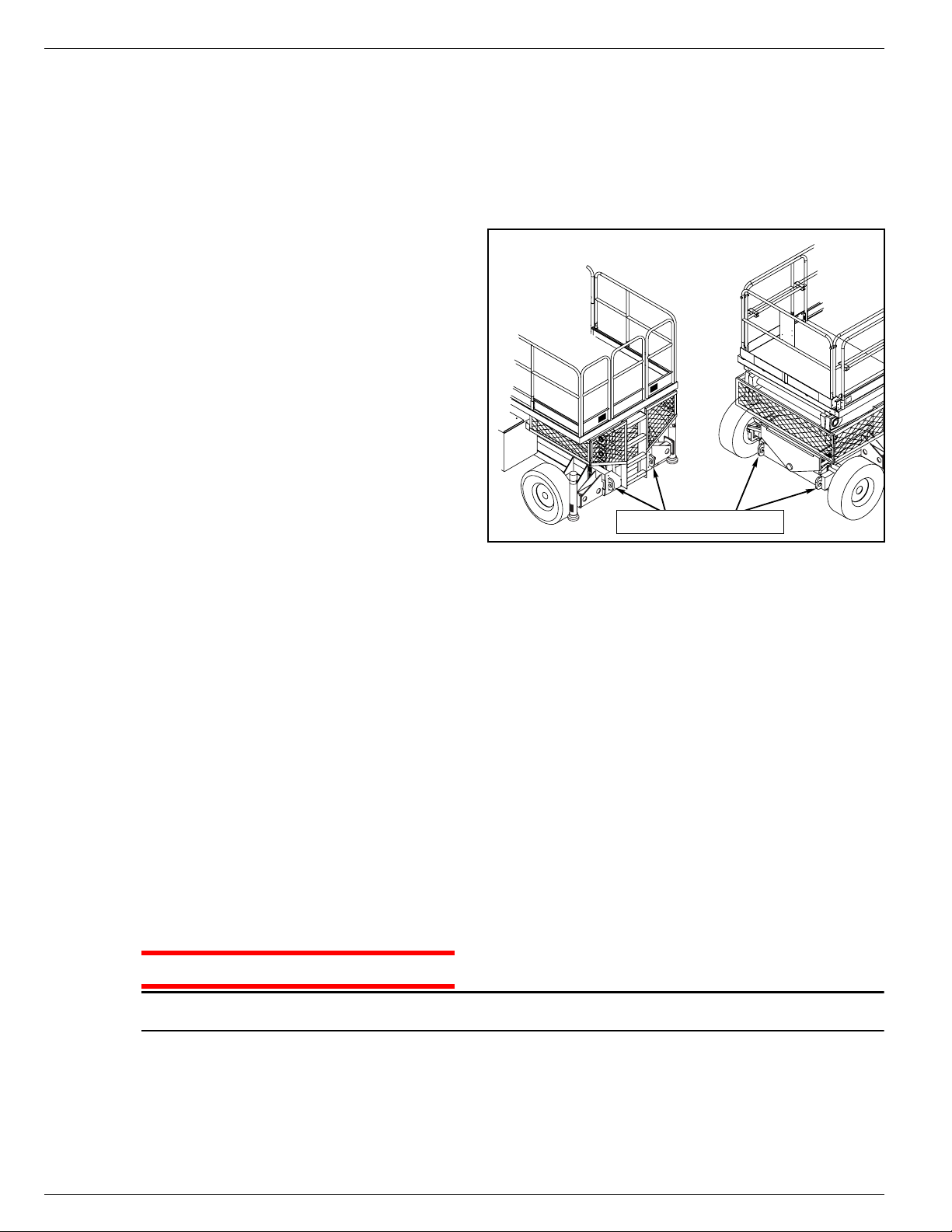
067903-025 LX31/LX41/LX50 Transport der Arbeitsbühne
ACHTUNG
T
RANSPORT
T
RANSPORTVORBEREITUNGEN
1. Arbeitsbühne völlig absenken.
2. Batterieminuskabel (-) vom Batteriepol abklemmen.
3. Steuerpult am vorderen Schutzgeländer festbinden.
4. Hubgestänge am Rahmen festbinden.
H
K
1. Gurte nur an den Verankerungs-/Hublaschen
2. Die Arbeitsbühne auf dem Transportfahrzeug
3. Die Räder mit Keilen sichern.
4. Arbeitsbühne am Transportfahrzeug mit
EBEN
RAN
DER
des Fahrwerks anbringen.
in Transportstellung bringen.
Ketten oder Gurten angemessener Stärke
befestigen, die an den Verankerungs/Hublaschen des Fahrwerks angebracht
werden.
DURCH
A
RBEITSBÜHNE
EINEN
Abbildung 36:
Rückansicht
Transport der Arbeitsbühne
Frontansicht
Verankerungs-/Hublaschen
A
RBEITSBÜHNE
W
INDE AUF EINEN
ANMERKUNG:
1. Die Maschine auf einen LKW oder Anhänger befördern.
A. Maschine auf das Transportfahrzeug
B. Maschine bei
2. Arbeitsbühne am Transportfahrzeug mit Ketten oder Gurten angemessener Stärke befestigen, die an den
Verankerungs-/Hublaschen des Fahrwerks angebracht werden.
Bei Windenbetrieb nicht schneller als 0,3 m/s
a. Die Arbeitsbühne auf die Rampe befördern und in Transportposition bringen.
b. Die Räder gerade ausrichten und den Motor abstellen.
c. Die Räder mit Keilen sichern.
a. Die Arbeitsbühne bis zur Rampe bewegen.
b. Das Kabel der Winde an die Verankerungs-/Hublaschen anbringen.
c. Feststellbremse lösen (siehe „Schleppen oder Windenbetrieb“ auf Seite 56).
d. Die Arbeitsbühne in Transportposition ziehen.
e. Die Räder mit Keilen sichern.
DURCH
LKW
Verwendung einer Winde
F
AHREN
ODER
fahren
ODER
A
NHÄNGER
bewegen.
(1 ft/s)
:
auf das Transportfahrzeug befördern:
Z
IEHEN
LADEN
MIT EINER
Ein Überspannen der durch Verankerungs-/Hublaschen hindurch geführten Ketten oder Gurte kann zur
Beschädigung der Arbeitsbühne führen.
Seite 14 Betriebsanleitung
Page 61
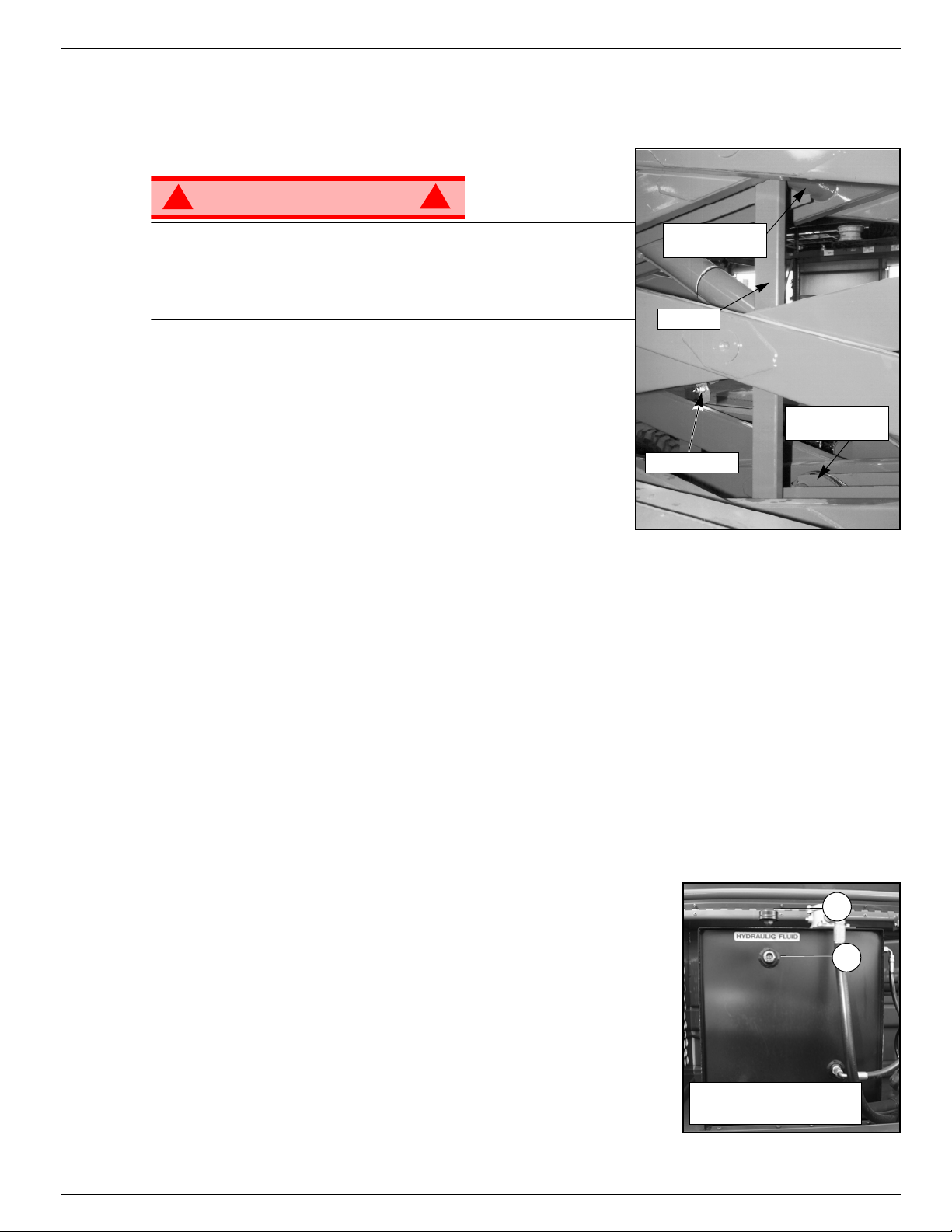
Wartung 067903-025 LX31/LX41/LX50
WARNUNG
!
!
Unteres
Scherenlager
Oberes
Scherenlager
Stütze
Sperrbolzen
2
1
1. Flüssigkeitsschauglas
2. Behälterdeckel
W
ARTUNG
B
LOCKIEREN
Wartungsarbeiten im Hubgestellbereich der Arbeitsbühne niemals bei
hochgefahrener Arbeitsbühne vornehmen, ohne vorher das Hubgestell
zu blockieren.
NIEMALS
Stützstrebe eingesetzt oder verstaut wird.
INSETZEN DER STÜTZE
E
1. Arbeitsbühne auf festem, waagerechtem Boden parken.
2. Sicherstellen, dass der Arbeitsbühnen-Notaustaster
3. Den Schalter Arbeitsbühne/Fahrwerk auf „Fahrwerk“ (CHASSIS)
4. Motor mit Hilfe der Fahrwerk-Steuerorgane starten.
5. Drosselklappenknopf hineindrücken; der Knopf bleibt in dieser
6. Sicherungsbolzen der Stütze von der linken Maschinenseite her ausklinken. Scherenstütze nach links
7. Den Absenkknopf drücken und die Arbeitsbühne allmählich absenken, bis diese auf der Stütze aufliegt.
8. Die Drosselklappe wird durch Eindrücken des Drosselklappenknopfes gelöst. Der Knopf bleibt in der
im Bereich des Hubgestells stehen, während die
EINGESCHALTET ist.
drehen.
Stellung, und die Motordrehzahl steigt an. Arbeitsbühne mit Hilfe
des Hochfahrknopfs so weit heben, bis sich die Scherenstütze in Senkrechtstellung schwenken lässt.
schwenken, bis diese zwischen den beiden mittleren Scherenlagern senkrecht steht.
gedrückten Position, und der Motor läuft im Leerlauf.
DES
H
UBGESTELLS
Abbildung 37:
Blockieren des Hubgestells
NTFERNEN DER STÜTZE
E
1. Arbeitsbühne mit Hilfe der Fahrwerk-Steuerorgane allmählich heben, bis die Scherenstütze die beiden
mittleren Scherenlager freigibt.
2. Scherenstütze nach rechts schwenken, bis der Sperrbolzen einrastet.
3. Den Absenkknopf drücken, um die Arbeitsbühne völlig abzusenken.
4. Sicherstellen, dass der Drosselklappenknopf ausgerastet ist und der Schalter Arbeitsbühne/Fahrwerk auf
„Arbeitsbühne“ (PLATFORM) steht.
H
YDRAULIKFLÜSSIGKEIT
Behälter für die Hydraulikflüssigkeit
Der Behälter für die Hydraulikflüssigkeit befindet sich im Aggregat.
ANMERKUNG:
1. Die Arbeitsbühne muss immer völlig abgesenkt sein.
2. Flüssigkeitsstand am Flüssigkeitsschauglas überprüfen.
3. Um die entsprechende Flüssigkeit einzufüllen, den Behälterdeckel
entfernen.
Nie Flüssigkeit zufügen, wenn die Arbeitsbühne hochgefahren ist.
Abbildung 38:
Betriebsanleitung Seite 15
Page 62

067903-025 LX31/LX41/LX50 Wartung
WARNUNG
!
!
B
ATTERIEWARTUNG
Abbildung 39:
Gefahr durch explosives Gasgemisch. Funken, Flammen und
Rauchwaren von der Batterie fernhalten.
Beim Umgang mit Batterien ist stets eine Schutzbrille zu tragen.
Batterieflüssigkeit ist stark ätzend. Jede ausgelaufene Flüssigkeit
muss durch gründliches Spülen mit sauberem Wasser entfernt werden.
Batterien stets durch UpRight-Batterien oder solche ersetzen, die vom
Hersteller genehmigt sind.
Flüssigkeitsstand der Batterie wöchentlich kontrollieren,
insbesondere, wenn die Arbeitsbühne in einem warmen, trockenen
Klima eingesetzt wird.
Steht die Batterieflüssigkeit weniger als 10 mm (3/8 in.) über den
Platten, NUR mit destilliertem Wasser auffüllen. Kein Leitungswasser
mit hohem Mineralanteil verwenden, da dies die Lebensdauer der
Batterie verkürzt.
Batterien und Kabel sollten regelmäßig auf Anzeichen von Rissen im
Gehäuse, austretende Batterieflüssigkeit und Korrosion der
Batteriepole untersucht werden. Kabel auf Verschleißstellen und Brüche in der Isolation sowie auf gebrochene
Klemmen untersuchen.
Hinweise zur Verlängerung der Batterielebensdauer und vollständige Wartungsarbeiten sind im
Wartungshandbuch zu finden.
Batteriefach
Seite 16 Betriebsanleitung
Page 63
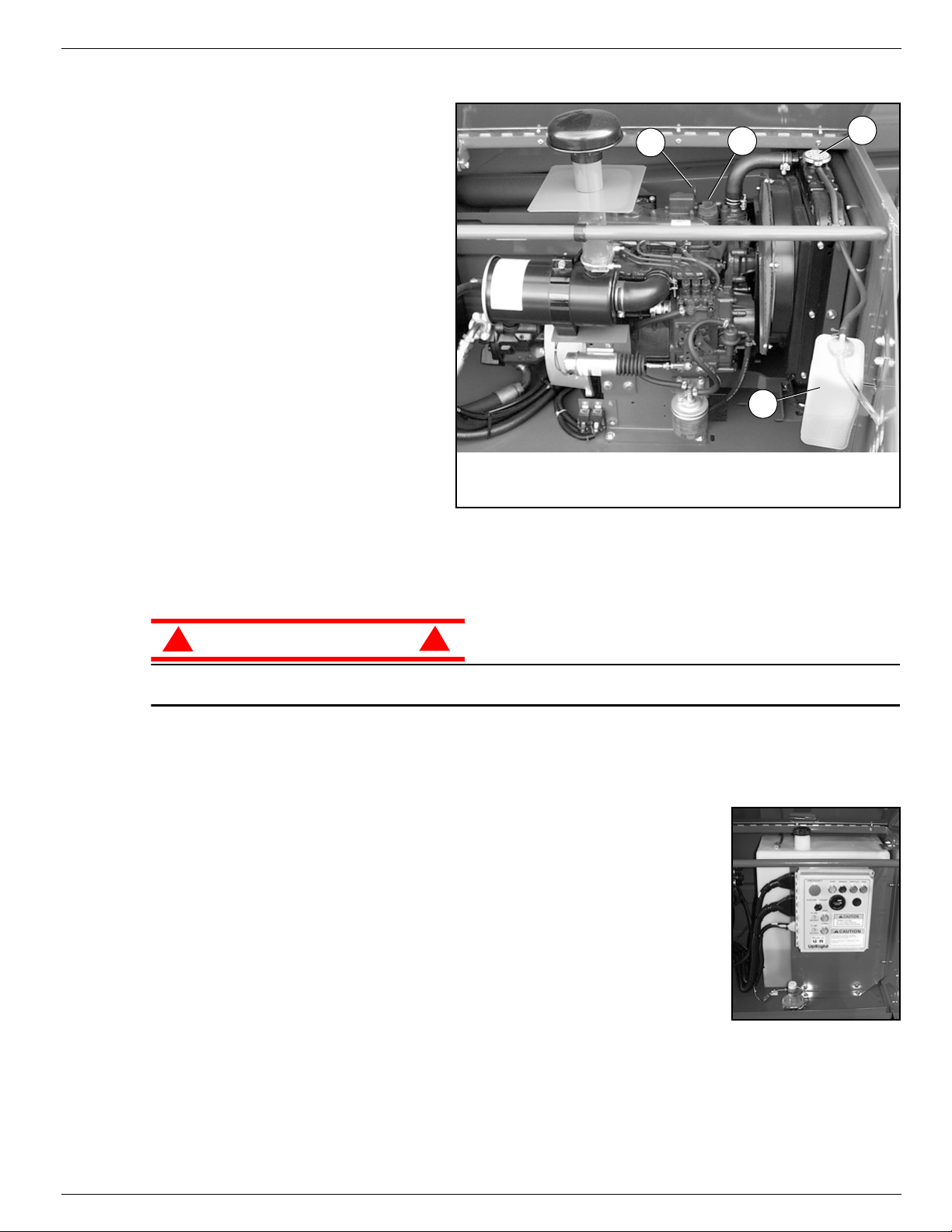
Wartung 067903-025 LX31/LX41/LX50
ACHTUNG
!
!
M
OTOR
Motor
1
ÜHLMITTEL
K
Der Nachfüllbehälter für das Kühlmittel ist
an der Innenseite der Tür des Aggregats
angebracht.
1. Den Deckel am Nachfüllbehälter
entfernen.
2. Kühlmittel bis zur Markierung „Vo ll “
(FULL) auffüllen.
Abbildung 40:
4
3
ANMERKUNG:
solange nicht entfernen, wie der Motor noch
heiß ist.
L
Ö
Der Motor
Motoröl überprüft und aufgefüllt wird. Zum
Wechsel des Ölfilters siehe
Wartungshandbuch.
1. Den Ölmessstab entfernen und die
Markierungen für den Ölstand überprüfen.
2. Bei niedrigem Ölstand die Öleinfüllkappe entfernen.
3. Mit entsprechendem Motoröl auffüllen (siehe mitgeliefertes Handbuch für die Motorwartung).
Kühlmittel NICHT bei heißem Motor oder Kühler prüfen, da heißes Kühlmittel schwere Verbrennungen
verursachen kann.
Den Kühlerverschlussdeckel
darf nicht laufen
wenn das
,
1. Kühlerkappe
2. Nachfüllbehälter für Kühlmittel
2
3. Öleinfüllkappe
4. Ölmessstab
RAFTSTOFF
K
Abbildung 41:
Der Kraftstoffbehälter befindet sich im Steuermodul hinter der Steuerung für das
Fahrwerk. Der Behälter ist durchsichtig. Von außen den Flüssigkeitsstand im
Behälter überprüfen.
Betriebsanleitung Seite 17
Kraftstoffversorgung
Page 64

067903-025 LX31/LX41/LX50 Plan für vorbeugende Wartung
WARNUNG
!
!
P
LAN FÜR VORBEUGENDE
W
ARTUNG
Zur vollständigen Durchsicht gehören regelmäßige visuelle und Funktionsprüfungen, sowie regelmäßige
kleineren Einstellungen, mit denen eine ordnungsgemäße Funktion gesichert wird. Eine tägliche Prüfung
vermeidet anormalen Verschleiß und verlängert die Lebensdauer aller Systeme. Inspektion und Wartung
müssen in regelmäßigen Abständen durchgeführt werden. Inspektion und Wartung dürfen nur von Personen
vorgenommen werden, die mit den elektrischen und mechanischen Vorgängen der Maschine vertraut sind.
Machen Sie sich vor Durchführung der vorbeugenden Wartung mit der Bedienung der Maschine vertraut.
Das Hubgestell immer blockieren, wenn bei ausgefahrener Arbeitsbühne innerhalb des
Scherenmechanismus Wartungsarbeiten durchgeführt werden müssen (siehe Seite 59).
Die Kontrollliste zur täglichen vorbeugenden Wartung gilt für Wartungsarbeiten der Maschine. Die Kontrollliste
zur täglichen vorbeugenden Wartung kopieren und die Tabelle als Kontrollliste bei der Wartung verwenden.
K
ONTROLLLISTE
ARTUNGSLEGENDE
W
ZUR TÄGLICHEN
VORBEUGENDEN
ARTUNGSPROTOKOLL
W
W
ARTUNG
\
J = Ja/Akzeptabel
N = Nein/Nicht akzeptabel
R = Repariert/Akzeptabel
BESCHREIBUNG INSPEKTION ODER WARTUNG J N R
Batterie
Fahrwerk
Steuerkabel
Steuerpult
Antriebsmotor
Hubgestell
Notabsenkung
Gesamteinheit
Hydraulikflüssigkeit
Hydraulikpumpe
Batterieflüssigkeitsstand prüfen
Schläuche auf Klemm- und Reibstellen
prüfen
Schweißstellen auf Risse prüfen
Das Kabel auf äußerlichen Verschleiß,
Bandage oder Quetschstellen kontrollieren
Schalterfunktion prüfen
Auf Funktion und Lecks prüfen
Gestell auf Risse prüfen
Notsenkventil betätigen und auf
Brauchbarkeit prüfen
Auf Kollisionsschäden prüfen und reparieren
Flüssigkeitsstand kontrollieren
Schlauchverbindungen auf Lecks prüfen
Datum: _____________________________________
Eigentümer:__________________________________
Modell-Nr.:___________________________________
Serien-Nr.:___________________________________
Gewartet von: ________________________________
BESCHREIBUNG INSPEKTION ODER WARTUNG J N R
Hydrauliksystem
Schilder
Arbeitsbühnendeck und
Geländer
Reifen und Räder
Motoröl und Filter
Motor-Kraftstoffsystem
Motorkühlmittel
Antriebsnaben
Auf Lecks prüfen
Auf abblätternde, fehlende oder unlesbare
Schilder prüfen und diese ersetzen
Schweißstellen auf Risse prüfen
Deckzustand prüfen
Auf Schäden prüfen
Stand und Zustand prüfen
Auf Lecks prüfen
Kraftstoffstand prüfen
Auf Lecks prüfen
Luftfilter prüfen
Kühlmittelstand prüfen (bei kaltem Motor)
Auf Lecks prüfen
Seite 18 Betriebsanleitung
Page 65

Plan für vorbeugende Wartung 067903-025 LX31/LX41/LX50
NNNN
OOOOTTTTEEEESSSS
::::
Betriebsanleitung Seite 19
Page 66

067903-025 LX31/LX41/LX50 Schilder
S
CHILDER
Die Arbeitsbühne darf nur in Betrieb genommen werden, wenn diese Schilder angebracht und gut lesbar sind.
Die Anweisungen auf den Schildern lesen, verstehen und einhalten, wenn die Arbeitsbühne benutzt wird.
2
064913-000
LX31/LX41:
40
066562-201
060197-000
4
067480-200
13
22
027898-001
25
066558-201
LX50:
40
005223-908
5
061205-203
6
030768-002
7
064936-099
9
066552-200
11
067642-211
(Outrigger Units:
067642-204)
13
067480-201
(Outrigger Units)
VERWENDUNG DER HOCHARBEITSBÜHNE: Diese Hocharbeitsbühne dient zum Heben von Personen und deren Werkzeugen sowie
des für die Arbeit benötigten Materials. Sie ist für die Ausführung von Reparatur-und Montagearbeiten an hochgelegenen Arbeitsplätzen
(Decken, Kränen, Dachkonstruktionen, Gebäuden usw.) vorgesehen. Sämtliche anderen Einsatzzwecke der Hocharbeitsbühne sind verboten!
DIESE HOCHARBEITSBÜHNE IST NICHT ISOLIERT! Aus diesem Grund ist es dringend erforderlich, von stromführenden Teilen elektrischer
Geräte einen Sicherheitsabstand einzuhalten!
Es ist verboten, die zulässige Höchstbelastung zu überschreiten! Lesen Sie das Handbuch des Bedieners für mehr Einzelheiten.
Die Verwendung bzw. der Betrieb der Hocharbeitsbühne als Hebevorrichtung oder Kran ist verboten!
Den vorgeschriebenen manuellen Kraftaufwand NIE überschreiten. Lesen Sie das Handbuch des Bedieners für mehr Einzelheiten.
Alle Lasten stets gleichmäßig auf der Arbeitsbühne VERTEILEN.
Maschine NIEMALS in Betrieb nehmen, ohne zuvor das Arbeitsgelände auf Bodengefahren, wie z.B. Löcher, abschüssige Stellen, Unebenheiten,
Rinnsteine oder Schutt zu untersuchen und diese zu umgehen.
Maschine nur auf Standflächen BETREIBEN, deren Tragfähigkeit für die Radlasten ausreicht.
Die Maschine NICHT in Betrieb nehmen, wenn der Nennwert für die Windgeschwindigkeit überschritten wird. Lesen Sie das Handbuch
des Bedieners für mehr Einzelheiten.
BEI NOTFÄLLEN den Notausschalter drücken, um alle Antriebsfunktionen zu deaktivieren.
FALLS während des Hochfahrens der Arbeitsbühne ein WARNSIGNAL ERTÖNT, sofort STOPPEN und die Arbeitsbühne vorsichtig absenken.
Maschine auf eine feste, waagerechte Standfläche bringen.
Es ist verboten, das Geländer der Arbeitsbühne zu besteigen, auf diesem zu stehen oder von der Arbeitsbühne her Gebäude, Stahl- oder
vorgefertigte Betonbauteile zu besteigen!
Der Abbau der Tür oder anderer Teile des Geländers ist verboten! Es ist immer zu kontrollieren, ob die Tür geschlossen und sicher verriegelt ist!
Es ist verboten, die Tür offen zu lassen wenn die Arbeitsbühne angehoben wird!
Es ist verboten, die Höhe bzw. Reichweite der Arbeitsbühne durch Aufstellen von Leitern, Gerüsten oder ähnlichen Gegenständen zu vergrößern!
An der Maschine NIEMALS Wartungsarbeiten durchführen, wenn die Arbeitsbühne hochgefahren ist, ohne das Hubgestell zu blockieren.
Maschine vor Benutzung gründlich auf gerissene Schweißnähte, lose oder fehlende Metallteile, Hydrauliklecks, lose Kabelanschlüsse
und beschädigte Kabel oder Schläuche ÜBERPRÜFEN.
Vor Benutzung SICHERSTELLEN, dass alle Schilder angebracht und gut lesbar sind.
Maschine NIEMALS in Betrieb nehmen, wenn diese beschädigt ist, nicht einwandfrei funktioniert oder deren Schilder beschädigt sind oder fehlen.
Die Außerkraftsetzung von Sicherheitseinrichtungen ist verboten und stellt für die auf der Hocharbeitsbühne und in ihrer Reichweite
befindlichen Personen eine Gefahr dar.
Batterie NIEMALS in der Nähe von Funken oder bei offener Flamme aufladen. Beim Laden von Batterien wird explosives Wasserstoffgas freigesetzt.
Modifikationen der Hocharbeitsbühne sind verboten bzw. nur mit Genehmigung von UpRight zulässig.
Arbeitsbühne NACH GEBRAUCH vor unbefugter Benutzung sichern, indem alle Schlüsselschalter ausgeschaltet werden und der Schlüssel abgezogen wird.
067195-201
14
067478-200
15
LX31: 064910-011
26
LX41: 064910-014
26
26
LX50: 064910-008
067822-201
3434
066556-200
41
NA
42
43
066556-201
(Outrigger Units)
NA
067481-201
12
17
063423-200
21
38
066561-201
066551-201
44
066551-203
45
(Outrigger Units)
Seite 20 Betriebsanleitung
Page 67

Schilder 067903-025 LX31/LX41/LX50
Hinten
Abbildung 42:
Lage der Sicherheitsschilder
Bedienelemente der Arbeitsbühne
Stromversorgung
Innen
Steuerpult des Fahrwerks
Steuermodul
Vo rn
Betriebsanleitung Seite 21
Page 68

067903-025 LX31/LX41/LX50 Technische Daten
T
ECHNISCHE
D
ATEN
Änderung technischer Daten ohne vorheirige Mitteilung vorbehalten. Siehe Wartungshandbuch für Informatio-
nen über Wartung und Reparatur. Siehe Ersatzteilhandbuch für eine Abbildung der Teile. An heißen Tagen bzw.
bei starker Beanspruchung kann sich dieLeistung verringern. Entspricht allen Sicherheitsandforderungen des
Landes oder übertrifft diese.
BESCHREIBUNG LX31 LX41 LX50
Arbeitsbühnengröße (zwischen den Fußblechen)
Standard
Ausziehdeck ausgezogen
Max. Arbeitsbühnen-Tragfähigkeit
Standard
Mit Option für den hinteren Teil der
Arbeitsbühne
Auf Verlängerung
Max. Personenzahl
Standard
Mit Option für den hinterenTeil der
Arbeitsbühne
Höhe
Arbeitshöhe
Max. Arbeitsbühnenhöhe
Min. Arbeitsbühnenhöhe
Fahrbare Höhe
Abmessungen
Gewicht, Standard 2rad:
Gewicht, Doppelarbeitsbühne 2rad:
Gesamtbreite
Gesamthöhe, Schutzgeländer hoch
Gesamthöhe, Schutzgeländer unten
Gesamtlänge, Deck eingefahren
Gesamtlänge, Deck ausgezogen
Fahrgeschwindigkeit
Arbeitsbühne gesenkt
Arbeitsbühne gehoben
Systemspannung
Hydrauliktank-Füllmenge
Max. Hydrauliksystemdruck
Hydraulikflüssigkeit
Normaltemperaturen: über 0 °C [32 °F]
Tieftemperaturen: unter 0 °C [32 °F]
Extremtemperaturen: unter -17 ° C [0 °F]
Hubsystem
Hubgeschwindigkeit
Antrieb
Fahrsteuerung
Steuersystem
Fahrantrieb
Reifen
Luftdruck der Reifen
Feststellbremsen
Wendekreisradius (innen)
Max. Steigfähigkeit:
Radstand
Bodenfreiheit
Schutzgeländer
Geräuschpegel
4rad:
4rad:
2rad:
4rad:
2rad:
4rad:
2rad:
4rad:
3,96 m x 1,73 m [
4,83 m x 1,73 m [
11,45 m [
4314 kg [
4436 kg [
4645 kg [
4767 kg [
0 bis 5,0 km/h [
0 bis 0,48 km/h [
107 L [
Ein einstufiger Hubzylinder Ein einstufiger Hubzylinder Zwei einstufige Hubzylinder
Anheben: 40 s Absenken: 52 s Anheben: 45 s Absenken: 60 s Anheben: 80 s Absenken: 112 s
Kubota Diesel 20 PS, 3 Zylinder,
Stufenloser, einhändiger Joystick Stufenloser, einhändiger Joystick Stufenloser, einhändiger Joystick
2 hydraulische Radmotoren
4 hydraulische Radmotoren
10 - 16,5 NHS 8 PR 10 - 16,5 NHS 8 PR 10 - 16,5 NHS 8 PR, ausgeschäumt
Doppelte Scheibe, federbelastet,
hydraulische Freigabe
1,1 m [
umklappbar einschl. Tür
156 in. x 68 in.
190 in. x 68 in.
2000 lbs.
907 kg [
1750 lbs.
794 kg [
500 lbs.
227 kg [
5 Personen 5 Personen 4 Personen
5 Personen 4 Personen 3 Personen
37 ft. 6 in.
31 ft.
9,45 m [
56,3 in.
1,43 m [
26 ft. 3 in.
8 m [
9511 lbs.
9780 lbs.
10241 lbs.
10440 lbs.
90 in.
2,29 m [
99,8 in.
2,53 m [
64,5 in.
1,64 m [
160 in.
4,02 m [
192 in.
4,89 m [
0 bis 3,1 mph
0 bis 0,5 mph
12 V Gleichstrom 12 V Gleichstrom 12 V Gleichstrom
28,3 US-Gallonen
3000 psi
207 bar [
ISO 46 ISO 46 ISO 46
ISO 32 ISO 32 ISO 32
ISO 15 ISO 15 ISO 15
wassergekühlt
Proportional Proportional Proportional
50 psi
3,4 bar [
48 in.
1,22 m [
30 %
17° [
]
35 %
19° [
]
114,5 in.
2,9 m [
116 in.
2,95 m [
9,5 in.
0,24 m [
43,5 in.
] hoch,
] 3,96 m x 1,73 m [
] 4,83 m x 1,73 m [
] 680 kg [
] 567 kg [
] 227 kg [
] 14,34 m [
] 12,34 m [
]1,66 m [
]8 m [
]
]
]
]
]2,29 m [
] 2,76 m [
]1,87 m [
] 4,02 m [
] 4,89 m [
] 0 bis 5,0 km/h [
] 0 bis 0,48 km/h [
] 107 L [
] 207 bar [
]3,4 bar [
]1,22 m [
]
]
] 0,24 m [
5026 kg [
5148 kg [
5357 kg [
5479 kg [
Kubota Diesel 20 PS, 3 Zylinder,
2 hydraulische Radmotoren
4 hydraulische Radmotoren
Doppelte Scheibe, federbelastet,
hydraulische Freigabe
1,1 m [
umklappbar einschl. Tür
156 in. x 68 in.
190 in. x 68 in.
1500 lbs.
1250 lbs.
500 lbs.
47 ft. 3 in.
40 ft. 6 in.
65,3 in.
26 ft. 3 in.
11080 lbs.
11349 lbs.
11810 lbs.
12079 lbs.
90 in.
109 in.
73,5 in.
160 in.
192 in.
0 bis 3,1 mph
0 bis 0,5 mph
28,3 US-Gallonen
3000 psi
wassergekühlt
50 psi
48 in.
30 %
17° [
35 %
19° [
114,5 in.
2,9 m [
116 in.
2,95 m [
9,5 in.
43,5 in.
] hoch,
] 3,96 m x 1,73 m [
] 4,83 m x 1,73 m [
] 454 kg [
]341 kg [
]227 kg [
]17,1 m
]15,1 m [
]1,9 m [
]8 m [
]
]
]
]
] 2,29 m [
]3 m [
]2,1 m [
] 4,02 m [
] 4,89 m [
] 0 bis 5,0 km/h [
] 0 bis 0,48 km/h [
] 107 L [
] 207 bar [
]ENTFÄLLT
] 1,22 m [
]
]
]
]
]0,24 m [
6242 kg [
6364 kg [
6460 kg [
6583 kg [
Diesel oder Kubota PS, 3 Zylinder,
2 hydraulische Radmotoren
4 hydraulische Radmotoren
Doppelte Scheibe, federbelastet,
hydraulische Freigabe
1,1 m [
umklappbar einschl. Tür
156 in. x 68 in.
190 in. x 68 in.
1000 lbs.
750 lbs.
500 lbs.
[56 ft.
49 ft. 6 in.
76 in.
26 ft. 3 in.
13761 lbs.
14030 lbs.
14242 lbs.
14513 lbs.
90 in.
118,3 in.
82,5 in.
160 in.
192 in.
0 bis 3,1 mph
0 bis 0,5 mph
28,3 US-Gallonen
3000 psi
wassergekühlt
48 in.
24 %
13,5° [
24 %
13,5° [
114,5 in.
2,9 m [
116 in.
2,95 m [
9,5 in.
43,5 in.
] hoch,
]
]
]
]
]
]
]
]
]
]
]
]
]
]
]
]
]
]
]
]
]
]
]
]
]
]
]
]
Seite 22 Betriebsanleitung
Page 69

NNNN
OOOOTTTTEEEESSSS
::::
Page 70

NNNN
OOOOTTTTEEEESSSS
::::
Page 71

Call Toll Free in U.S.A.
1-800-926-LIFT
Page 72

USA
TEL: (1) 800-926-5438 or (1) 559-662-3900
FAX: (1) 559-673-6184
Parts FAX: (1) 800-669-9884
801 South Pine Street
Madera, California 93637
http://www.upright.com
UROPE
E
TEL: +353 1 620 9300
FAX: +353 1 620 9301
Unit S1, Park West Industrial Park
Friel Avenue
Nangor Road
Dublin 12, Ireland
Local Distributor:
TATS
É
TÉL. : (1) 800-926-5438 ou (1) 559-662-3900
TÉLÉC. : (1) 559-673-6184
TÉLÉC. (pièces) : (1) 800-669-9884
801 South Pine Street
Madera, California 93637 É.-U.
http://www.upright.com
UROPE
E
TÉL. : +353 1 620 9300
TÉLÉC. : +353 1 620 9301
Unit S1, Park West Industrial Park
Friel Avenue
Nangor Road
Dublin 12, Irlande
-U
NIS
USA
TEL: (1) 800-926-5438 oder (1) 559-662-3900
FAX: (1) 559-673-6184
FAX für Ersatzteile: (1) 800-669-9884
801 South Pine Street
Madera, California 93637 USA
http://www.upright.com
Distributeur local :
Ortsvertrieb:
UROPA
E
TEL: +353 1 620 9300
FAX: +353 1 620 9301
Unit S1, Park West Industrial Park
Friel Avenue
Nangor Road
Dublin 12, Irland
067903-025
08-02
 Loading...