

Page 1

Operator Manual
LX31/41/50
SERIAL NO. 4022 to Current
WARNING
All personnel shall carefully read, understand and follow all safety rules,
operating instructions, and the Scaffold Industry Association’s
MANUAL OF RESPONSIBILITIES of ANSI A92.6-1999 before performing
maintenance on or operating any UpRight Aerial Work Platform.
067903-004R1
Page 2
LX31/41/50
Gasoline, Dual Fuel, and Diesel Models
Serial Numbers 4022 - Current
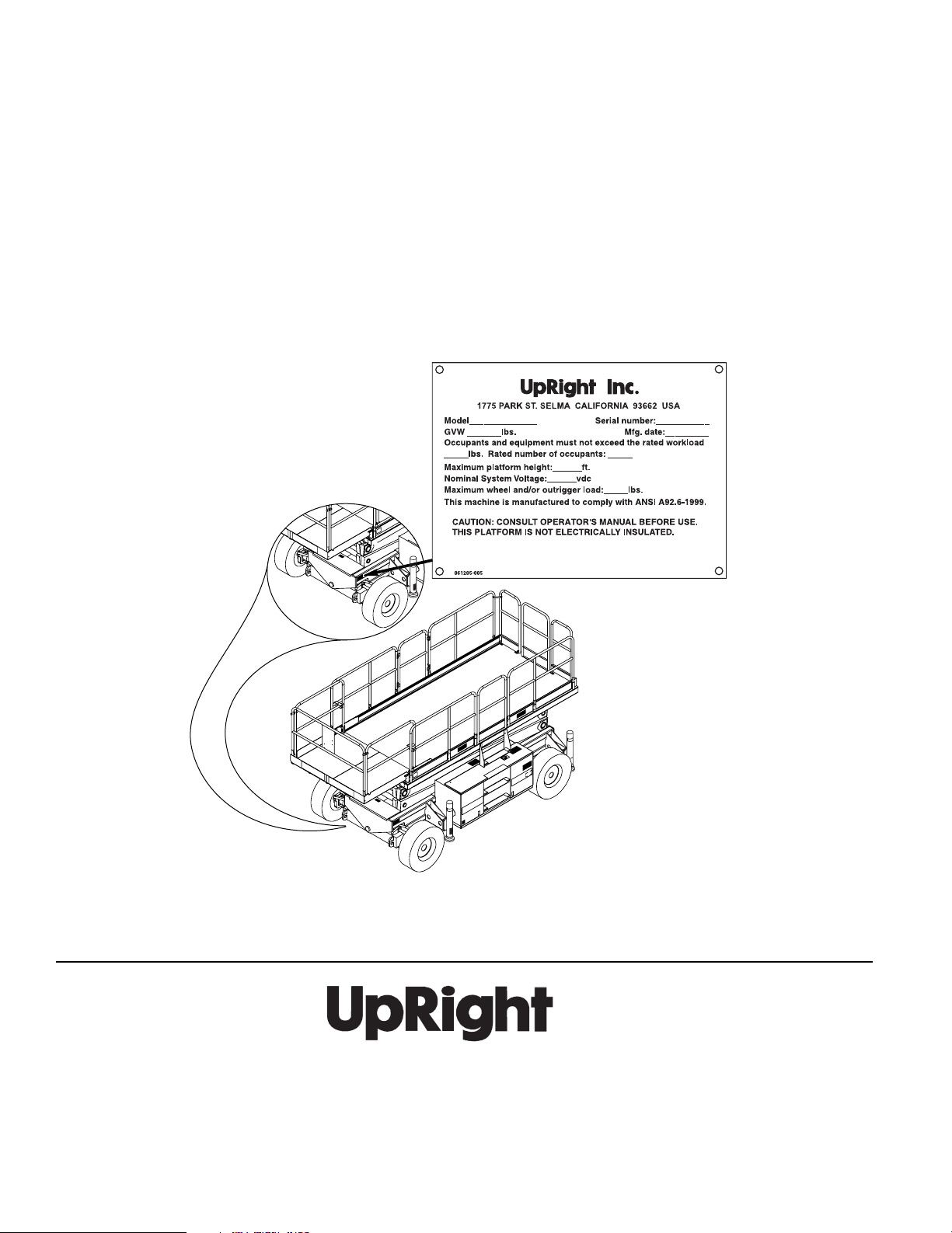
When contacting UpRight for service or parts information, be sure to include the MODEL and SERIAL NUMBERS
from the equipment nameplate. Should the nameplate be missing, the SERIAL NUMBER is also stamped on top of
the chassis above the left front axle pivot.
UpRight, Inc.
801 South Pine Street
Madera, California 93637
TEL: 559-662-3900
FAX: 559-673-6184
PA R T S : 1 - 8 8 8- UR -PA R TS
PARTS FAX: 1-800-669-9884
Call Toll Free in U.S.A.
1-800-926-LIFT
UpRight
Unit S1, Park West Industrial Park
Friel Avenue
Nangor Road
Dublin 12, Ireland
TEL: +353 1 620 9300
FAX: +353 1 620 9301
Page 3
PERATOR
O
M
ANUAL
WARNING
All personnel shall carefully read, understand and follow all safety rules, operating
instructions, and the Scaffold Industry Association’s MANUAL OF
RESPONSIBILITIES (ANSI A92.6) before performing maintenance on or operating
any UpRight Aerial Work Platform.
Safety Rules
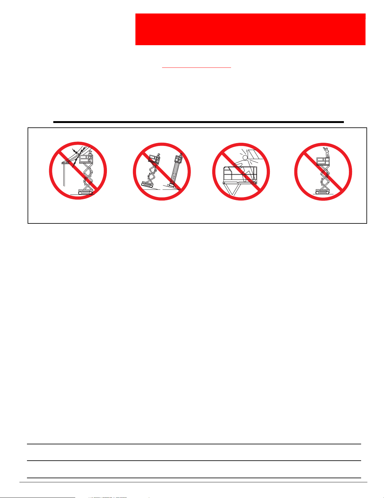
Electrocution Hazard
Electrocution Hazard Tip Over Hazard
Electrocution HazardElectrocution Hazard
Tip Over Hazard Collision Hazard
Tip Over HazardTip Over Hazard
Collision Hazard Fall Hazard
Collision HazardCollision Hazard
Fall Hazard
Fall HazardFall Hazard
NEVER operate the machine within ten
(10) feet of power lines.
THIS MACHINE IS NOT INSULATED.
•
NEVER
•
NEVER
•
NEVER
curbs, or debris.
•
ALWAYS
•
NEVER
•
NEVER
•
LOOK
•
DISTRIBUTE
•
NEVER
•
NEVER
•
INSPECT
hoses, loose wire connections, and wheel bolts.
•
NEVER
•
IF ALARM SOUNDS
surface.
•
IN CASE OF EMERGENCY
•
NEVER
•
NEVER
•
NEVER
turer’s written consent.
•
VERIFY
•
NEVER
•
AFTER USE
exceed the maximum platform load. See “Specifications” on page 20.
operate the machine if all guardrails are not properly in place and secured with all fasteners properly torqued.
operate the machine without first surveying the work area for surface hazards such as holes, drop-offs, bumps,
close and secure the entrance after entering the platform.
use ladders or scaffolding on the platform.
attach overhanging loads or increase platform size.
up, down and around for overhead obstructions and electrical conductors.
all platform loads evenly on the platform.
use damaged equipment. (Contact UpRight for instructions. See toll free phone number on inside back cover.)
change operating or safety systems.
the machine thoroughly for cracked welds, loose or missing hardware, hydraulic leaks, damaged cables or
climb down elevating assembly when the platform is elevated.
while the platform is elevated, STOP, carefully lower the platform. Move the machine to a firm, level
perform service on the machine while the platform is elevated without blocking the elevating assembly.
recharge batteries near sparks or open flame; batteries that are being charged emit explosive hydrogen gas.
replace any component or part with anything other than original UpRight replacement parts without the manufac-
that all labels are in place and legible before using.
tow the machine. Transport by truck or trailer only.
, secure the work platform against unauthorized use by turning the key switch off and removing the key.
NEVER operate the boom or drive with
the platform elevated unless on firm,
push the Emergency Stop button to cut power to all machine functions.
level surface.
NEVER position the platform without
first checking for overhead obstructions
or other hazards.
NEVER climb, stand or sit on the
platform guardrails or midrail.
California Proposition 65 Warning
Gasoline and diesel engine exhaust and some of their constituents are known to the State of California to
cause cancer, birth defects, and other reproductive harm.
Battery Posts, terminals and related accessories contain lead compounds, chemicals known to the State of
California to cause cancer and reproductive harm. Wash hands after handling.
Page 1
Page 4

067903-004R1 LX Series Work Platform
C
ONTENTS
Introduction . . . . . . . . . . . . . . . . . . . . . . . . . . . . . . . . . . . . . . . . . . . . . . . . . . . . . . . . . . . . . . . . . . . . . . . . . 3
General Description . . . . . . . . . . . . . . . . . . . . . . . . . . . . . . . . . . . . . . . . . . . . . . . . . . . . . . . . . . . . . . . . . . 3
Controls and Indicators . . . . . . . . . . . . . . . . . . . . . . . . . . . . . . . . . . . . . . . . . . . . . . . . . . . . . . . . . . . . . . . 4
Pre-Operation & Safety Inspection . . . . . . . . . . . . . . . . . . . . . . . . . . . . . . . . . . . . . . . . . . . . . . . . . . . . . . 5
System Function Inspection . . . . . . . . . . . . . . . . . . . . . . . . . . . . . . . . . . . . . . . . . . . . . . . . . . . . . . . . . . . . . . . . . . . . 5
Operation . . . . . . . . . . . . . . . . . . . . . . . . . . . . . . . . . . . . . . . . . . . . . . . . . . . . . . . . . . . . . . . . . . . . . . . . . . . 7
Switching Fuels (Dual Fuel Only) . . . . . . . . . . . . . . . . . . . . . . . . . . . . . . . . . . . . . . . . . . . . . . . . . . . . . . . . . . . . . . . . 7
Travel with Platform Lowered. . . . . . . . . . . . . . . . . . . . . . . . . . . . . . . . . . . . . . . . . . . . . . . . . . . . . . . . . . . . . . . . . . . 7
Travel with Work Platform Elevated . . . . . . . . . . . . . . . . . . . . . . . . . . . . . . . . . . . . . . . . . . . . . . . . . . . . . . . . . . . . . . 8
Steering . . . . . . . . . . . . . . . . . . . . . . . . . . . . . . . . . . . . . . . . . . . . . . . . . . . . . . . . . . . . . . . . . . . . . . . . . . . . . . . . . . . 8
Raising and Lowering the Platform . . . . . . . . . . . . . . . . . . . . . . . . . . . . . . . . . . . . . . . . . . . . . . . . . . . . . . . . . . . . . . 8
Emergency Lowering . . . . . . . . . . . . . . . . . . . . . . . . . . . . . . . . . . . . . . . . . . . . . . . . . . . . . . . . . . . . . . . . . . . . . . . . . 9
Serial # 4022 to 4274 . . . . . . . . . . . . . . . . . . . . . . . . . . . . . . . . . . . . . . . . . . . . . . . . . . . . . . . . . . . . . . . . . . . . . 9
LX31 and LX41, Serial # 4275 to Current . . . . . . . . . . . . . . . . . . . . . . . . . . . . . . . . . . . . . . . . . . . . . . . . . . . . . . 9
LX50, Serial # 4275 to Current . . . . . . . . . . . . . . . . . . . . . . . . . . . . . . . . . . . . . . . . . . . . . . . . . . . . . . . . . . . . . . 9
Leveling the Platform
(Outrigger equipped machines only) . . . . . . . . . . . . . . . . . . . . . . . . . . . . . . . . . . . . . . . . . . . . . . . . . . . . . . . . . . . . 10
Outrigger Switches and Indicator Lights . . . . . . . . . . . . . . . . . . . . . . . . . . . . . . . . . . . . . . . . . . . . . . . . . . . . . . 10
To Level the Platform (Extend the Outriggers) . . . . . . . . . . . . . . . . . . . . . . . . . . . . . . . . . . . . . . . . . . . . . . . . . 10
To Retract the Outriggers . . . . . . . . . . . . . . . . . . . . . . . . . . . . . . . . . . . . . . . . . . . . . . . . . . . . . . . . . . . . . . . . . 10
Towing or Winching . . . . . . . . . . . . . . . . . . . . . . . . . . . . . . . . . . . . . . . . . . . . . . . . . . . . . . . . . . . . . . . . . 11
Parking Brake Release. . . . . . . . . . . . . . . . . . . . . . . . . . . . . . . . . . . . . . . . . . . . . . . . . . . . . . . . . . . . . . . . . . . . . . . 11
After Use Each Day . . . . . . . . . . . . . . . . . . . . . . . . . . . . . . . . . . . . . . . . . . . . . . . . . . . . . . . . . . . . . . . . . . 11
Fold Down Guardrails . . . . . . . . . . . . . . . . . . . . . . . . . . . . . . . . . . . . . . . . . . . . . . . . . . . . . . . . . . . . . . . . 12
Fold Down Procedure. . . . . . . . . . . . . . . . . . . . . . . . . . . . . . . . . . . . . . . . . . . . . . . . . . . . . . . . . . . . . . . . . . . . . . . . 12
Erection Procedure. . . . . . . . . . . . . . . . . . . . . . . . . . . . . . . . . . . . . . . . . . . . . . . . . . . . . . . . . . . . . . . . . . . . . . . . . . 12
Transporting Work Platform. . . . . . . . . . . . . . . . . . . . . . . . . . . . . . . . . . . . . . . . . . . . . . . . . . . . . . . . . . . 13
Preparation for Shipment . . . . . . . . . . . . . . . . . . . . . . . . . . . . . . . . . . . . . . . . . . . . . . . . . . . . . . . . . . . . . . . . . . . . . 13
Lifting By Crane . . . . . . . . . . . . . . . . . . . . . . . . . . . . . . . . . . . . . . . . . . . . . . . . . . . . . . . . . . . . . . . . . . . . . . . . . . . . 13
Driving or Winching onto a Truck or Trailer . . . . . . . . . . . . . . . . . . . . . . . . . . . . . . . . . . . . . . . . . . . . . . . . . . . . . . . 13
Maintenance. . . . . . . . . . . . . . . . . . . . . . . . . . . . . . . . . . . . . . . . . . . . . . . . . . . . . . . . . . . . . . . . . . . . . . . . 14
Blocking Elevating Assembly . . . . . . . . . . . . . . . . . . . . . . . . . . . . . . . . . . . . . . . . . . . . . . . . . . . . . . . . . . . . . . . . . . 14
Brace Installation. . . . . . . . . . . . . . . . . . . . . . . . . . . . . . . . . . . . . . . . . . . . . . . . . . . . . . . . . . . . . . . . . . . . . . . . 14
Brace Removal . . . . . . . . . . . . . . . . . . . . . . . . . . . . . . . . . . . . . . . . . . . . . . . . . . . . . . . . . . . . . . . . . . . . . . . . . 14
Hydraulic Fluid . . . . . . . . . . . . . . . . . . . . . . . . . . . . . . . . . . . . . . . . . . . . . . . . . . . . . . . . . . . . . . . . . . . . . . . . . . . . . 15
Battery Maintenance . . . . . . . . . . . . . . . . . . . . . . . . . . . . . . . . . . . . . . . . . . . . . . . . . . . . . . . . . . . . . . . . . . . . . . . . 15
Engine . . . . . . . . . . . . . . . . . . . . . . . . . . . . . . . . . . . . . . . . . . . . . . . . . . . . . . . . . . . . . . . . . . . . . . . . . . . . . . . . . . . 16
Coolant . . . . . . . . . . . . . . . . . . . . . . . . . . . . . . . . . . . . . . . . . . . . . . . . . . . . . . . . . . . . . . . . . . . . . . . . . . . . . . . 16
Oil . . . . . . . . . . . . . . . . . . . . . . . . . . . . . . . . . . . . . . . . . . . . . . . . . . . . . . . . . . . . . . . . . . . . . . . . . . . . . . . . . . . 16
Fuel . . . . . . . . . . . . . . . . . . . . . . . . . . . . . . . . . . . . . . . . . . . . . . . . . . . . . . . . . . . . . . . . . . . . . . . . . . . . . . . . . . . . . 16
Diesel or Gasoline. . . . . . . . . . . . . . . . . . . . . . . . . . . . . . . . . . . . . . . . . . . . . . . . . . . . . . . . . . . . . . . . . . . . . . . 16
Propane (LP Gas) . . . . . . . . . . . . . . . . . . . . . . . . . . . . . . . . . . . . . . . . . . . . . . . . . . . . . . . . . . . . . . . . . . . . . . . 16
Preventative Maintenance . . . . . . . . . . . . . . . . . . . . . . . . . . . . . . . . . . . . . . . . . . . . . . . . . . . . . . . . . . . . 17
Daily Preventative Maintenance Check List . . . . . . . . . . . . . . . . . . . . . . . . . . . . . . . . . . . . . . . . . . . . . . . . . . . . . . . 17
Labels . . . . . . . . . . . . . . . . . . . . . . . . . . . . . . . . . . . . . . . . . . . . . . . . . . . . . . . . . . . . . . . . . . . . . . . . . . . . . 18
Specifications . . . . . . . . . . . . . . . . . . . . . . . . . . . . . . . . . . . . . . . . . . . . . . . . . . . . . . . . . . . . . . . . . . . . . . 20
Page 2 Operator Manual
Page 5
Introduction 067903-004R1 LX Series Work Platform
WARNING
!
!
I
NTRODUCTION
G
ENERAL
This manual covers the operation of the LX31, LX41 and LX50 Internal Combustion Work Platforms.
manual must be stored on the machine at all times.
D
ESCRIPTION
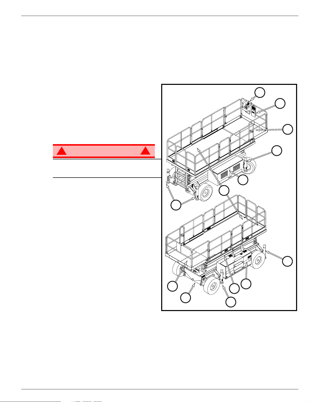
Figure 2:
1. Platform
LX Series Work Platform
3
The platform has a reinforced steel floor,
guardrails with midrail, toeboards and an
entrance gate at the rear and left side of the
platform. The guardrails can be folded down
for access through doors or for shipment.
2. Slide-out Deck
9
DO NOT
without guardrails properly assembled and in
place
use the maintenance platform
7
3. Platform Controls
1
The platform controls contain the controls to
operate the machine. It should be hung on
the front, left, or right guardrail.
4. Manual Case
5. Elevating Assembly
9
This
4
2
The platform is raised and lowered by the
elevating assembly;
• LX31 - a three section scissor assembly
powered by one single-stage lift cylinder.
• LX - a four section scissor assembly
powered by one single-stage lift cylinder.
• LX50 - a five section scissor assembly
powered by two single-stage lift cylinders.
6. Control Module
The control module contains the fuel tank,
hydraulic valve manifold, horn/alarms, battery, and chassis control panel.
7. Power Module
The power module contains the engine, the hydraulic pump, the hydraulic reservoir.
8. Chassis
The chassis is a structural frame that supports all the components of the Work Platform.
9. Outriggers (optional)
2
8
6
5
9
9
Operator Manual Page 3
Page 6
067903-004R1 LX Series Work Platform Controls and Indicators
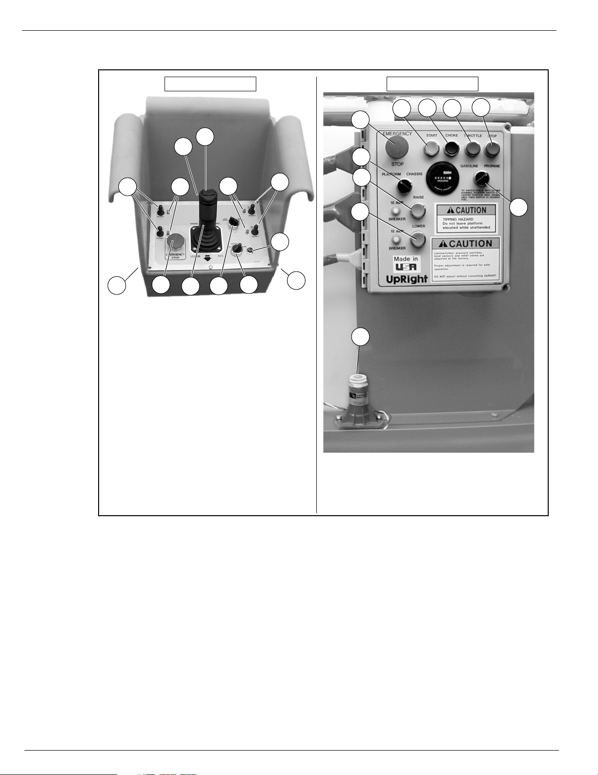
4*
2
1
3
7**
9
10
8
Outrigger Options
* Outrigger Switches and Outrigger Lights are installed on
outrigger equipped machines only.
** Outrigger selection is available on outrigger equipped
machines only.
5*
5*
4*
1 Steering Switch
2. Interlock Lever Switch
3. Control Lever
4. Outrigger Switches
5. Outrigger Indicator Lights
6. Emergency Stop Switch
7. Lift/Drive Switch
8. Drive Speed/Torque Selector Switch
9. Drive Enable Indicator
10. Key Switch
11. • Choke Button (dual fuel)
• Glow Plug Button (diesel)
6
11
1 Emergency Stop
2. Platform/Chassis Switch
3. Raise Button
4. Lower Button
5. Start Button
6. Glow Plug Button
7. Throttle Button
8. Stop Button
9. Level Sensor
10. Fuel Selector Switch
7
1
2
3
4
5
6
8
9
Platform Controls Chassis Controls
10
C
ONTROLS
AND
I
NDICATORS
Figure 3:
Controls and Indicators
Page 4 Operator Manual
Page 7
Pre-Operation & Safety Inspection 067903-004R1 LX Series Work Platform
WARNING
!
!
CAUTION
!
!
WARNING
!
!
P
RE
-O
PERATION
NOTE:
Carefully read, understand and follow all safety rules, operating instructions, labels and the Scaffold Industry
Association’s MANUAL OF RESPONSIBILITIES. Perform the following steps each day before use.
1. Open modules and inspect for damage, oil leaks or missing parts.
2. Check the hydraulic oil level sight gauge on the hydraulic tank with the platform fully lowered. Add fluid if
necessary.
3. Check that fluid level in the battery is correct (see “Battery Maintenance” on page 15).
4. Check the engine oil level and fuel level.
5. Check that all guardrails are in place, the slide-out deck extension is secured with the pin, and all fasteners are properly tightened.
6. Check tire pressure: LX31 and LX41 - 3,4 bar (
7. Carefully inspect the entire work platform for damage such as cracked welds in structural members,
loose or missing parts, oil leaks, damaged cables or hoses, loose connections and tire damage.
8. Carefully inspect the limit switches for signs of tampering.
9. Dual Fuel Models: set the dual fuel selector to the desired position. Set to the center position to purge
the system when switching fuels. If the machine is to be operated on propane, open the supply valve on
the tank
& S
AFETY
I
NSPECTION
). The LX50 is equipped with poly-filled tires.
50 psi
NOTE:
When using LP gas, use clean, water-free liquid petroleum gas, preferably from a bulk storage tank. Follow the
instructions located on the power module tray for filling the tank.
If you smell propane, close the supply valve on the tank immediately until you have located and
corrected the leak.
10. While the engine is cool, check the engine coolant level.
DO NOT check coolant when engine or radiator is hot; hot coolant can cause severe burns.
S
YSTEM
STAND CLEAR
Before operating the work platform, survey the work area for surface hazards such as holes, drop-offs,
bumps and debris.
Check in
Protect control console cable from possible damage while performing checks.
F
UNCTION
of the work platform while performing the following checks.
directions, including above the work platform, for obstructions and electrical conductors.
ALL
I
NSPECTION
1. Move the machine, if necessary, to an unobstructed area to allow for full elevation.
2. Place chassis and platform emergency stop switches in the ON position (Figure 3, Page 4) by pulling the
3. Verify that the platform/chassis switch is set to PLATFORM (Figure 3, Page 4).
4. Unhook the controller from the front guardrail. Firmly grasp the controller hanger in such a manner that
5. Turn the controller key switch clockwise to ON. Turn fully clockwise to start the engine, releasing the key
Operator Manual Page 5
buttons out.
the interlock lever switch can be depressed, while performing the following checks from the ground.
once the engine starts.
Page 8

067903-004R1 LX Series Work Platform Pre-Operation & Safety Inspection
NOTE:
If the engine is cold:
- on dual fuel models, hold the choke button in while starting the engine;
- on diesel models, depress the glow plug button and hold for 6 seconds to heat the glow plugs.
6. Position the Lift/Drive switch to the DRIVE position. The drive enable light should be ON.
7. With the speed range switch first in HIGH TORQUE and then in HIGH SPEED, depress the interlock
lever switch and slowly push the control lever to FORWARD then REVERSE positions to check for
speed and directional control. The farther you push or pull the control lever, the faster the machine will
travel.
8. Push steering switch RIGHT then LEFT to check for steering control.
9. Optional Outrigger Equipped Machines:
a. With the Lift/Outrigger/Drive switch in DRIVE, depress the interlock lever switch on the control lever
and position each Outrigger switch to the EXTEND position.
• Outriggers should be disabled. If an outrigger extends during this test
machine from service until it is repaired.
b. Turn the Drive/Outrigger/Lift switch to OUTRIGGER.
c. Depress the interlock lever switch on the control lever and position each Outrigger switch to the
EXTEND position to deploy all four (4) outriggers.
• Check the outrigger indicator lights; they should be ON.
NOTE:
When the platform is elevated 1 m (3 ft.) or higher the outrigger function should be disabled.
d. Depress the interlock lever switch on the control lever and position each Outrigger switch to the
RETRACT position.
• Partially retract all four (4) outriggers. The outrigger indicator lights should FLASH.
• Fully retract all four (4) outriggers. The outrigger indicator lights should be OFF.
10. Rehook the controller on the front guardrail.
11. Open the Control Module covers to gain access to the chassis controls and tilt sensor.
12. Turn the Platform/Chassis switch to CHASSIS.
13. Push the throttle button in. Push the Raise button to elevate platform while pushing the tilt sensor off of
level. The platform should only partially elevate and the tilt alarm should sound. If the platform continues to elevate and/or there is no alarm,
14. Release the tilt sensor and fully elevate the platform.
15. Visually inspect the elevating assembly, lift cylinder, cables and hoses for damage or erratic operation.
Check for missing or loose parts.
16. Lower the platform partially by pushing in on the Lower button, and check operation of the audible lowering alarm.
17. Open the chassis emergency lowering valve to check for proper operation by pulling and holding the
knob out (refer to “Emergency Lowering” on page 9). Once the platform is fully lowered, close the valve
by releasing the knob.
18. Turn the Platform/Chassis switch to PLATFORM.
19. Close and secure the module covers.
20. Enter the platform making sure the gate is latched.
21. Position the Lift/Drive switch to LIFT.
22. Depress the interlock lever switch and slowly push the control lever to UP to raise the platform; fully
actuate the control lever to check proportional lift speed. Slowly pull the control lever to the DOWN position to lower the platform. Check that the lowering alarm sounds.
23. Optional Outrigger Equipped Machines:
a. With the Lift/Outrigger/Drive switch in LIFT, depress the interlock lever switch on the control lever and
position any outrigger switch to the EXTEND position.
• Outriggers should be disabled. If an outrigger extends during this test,
and remove the machine from service until it is repaired.
24. Turn the controller key switch to OFF, push the Emergency Stop button, and dismount the platform.
and remove the machine from service until it is repaired.
STOP
. Remove the
STOP
. Lower the platform
STOP
Page 6 Operator Manual
Page 9

Operation 067903-004R1 LX Series Work Platform
WARNING
!
!
O
PERATION
NOTE:
Before
operating the work platform, ensure that the pre-operation and safety inspection has been completed,
any deficiencies have been corrected, and the operator has been thoroughly trained on this machine.
Never operate the work platform with the parking brakes released. Serious injury or damage could
result.
S
WITCHING
1. With the engine running, turn the fuel selector switch (Figure 3: “Controls and Indicators,” on page 4) to
the center position.
2. After the engine has quit running, select the appropriate fuel supply.
3. Restart the engine.
F
UELS
(D
UAL
F
UEL
O
NLY
)
T
RAVEL
1. Verify the following:
• the chassis Emergency Stop button is in the ON position (pull out)
• the drive enable indicator is ON
• the Platform/Chassis switch is on PLATFORM.
NOTE:
If the drive enable indicator is OFF, verify that the platform is fully lowered and (if so equipped) the outriggers
are fully retracted.
2. After mounting the platform, close and latch the gate. Check that the guardrails are in position and properly assembled, with the fasteners properly torqued.
3. Check that the route is clear of persons, obstructions, holes and drop-offs, and is capable of supporting
the wheel loads.
4. Check clearances above, below and to the sides of the platform.
5. Pull the controller Emergency Stop button out to the ON position.
6. Turn the controller key switch fully clockwise to start the engine, releasing the key once the engine
starts.
NOTE:
If the engine is cold, on dual fuel models, depress and hold the choke button in while starting the engine. On
diesel models, hold the glow plug button in for 6 seconds to heat the glow plugs.
7. Set the Lift/Drive switch to DRIVE.
8. Set the speed range switch to HIGH TORQUE.
9. Grasp the control lever so that the interlock lever switch is depressed (releasing the interlock lever switch
cuts power to controller). Slowly push or pull the control lever to FORWARD or REVERSE to travel in the
desired direction. The farther you push or pull the control lever from center, the faster the machine will
travel.
10. While moving, push the speed range switch to HIGH SPEED for travel on level surfaces or to HIGH
TORQUE for climbing grades or traveling in confined areas.
WITH
P
LATFORM
L
OWERED
Operator Manual Page 7
Page 10

067903-004R1 LX Series Work Platform Operation
T
RAVEL
Travel with the platform elevated
NOTE:
The work platform will travel at reduced speed when in the elevated position, and only if the front axle is
parallel with the rear axle.
1. Check that the route is clear of persons, obstructions, holes and drop-offs, is level and capable of supporting the wheel loads.
2. Check clearances above, below and to the sides of the platform.
3. Position the Lift/Drive switch to the DRIVE position.
4. Push the control lever to FORWARD or REVERSE for the desired direction of travel.
5. If the machine quits driving and the tilt alarm sounds, immediately lower the platform and move the
machine to a level location before re-elevating the platform.
S
TEERING
Push the steering switch
insure proper direction.
NOTE:
Steering is not self-centering. Wheels must be returned to the straight ahead position by operating the steering
switch.
WITH
W
ORK
RIGHT
P
LATFORM
on firm and level surfaces.
ONLY
or
to turn the wheels. Observe the tires while maneuvering to
LEFT
E
LEVATED
R
AISING
The machine must be on a firm, level surface, capable of supporting the weight of the machine. On
machines equipped with optional outriggers, use the outriggers to level the machine (refer to “Leveling the
Platform (Outrigger equipped machines only)” on page 10.
1. Position the Lift/Drive switch to LIFT.
2. While holding the control lever so the interlock lever switch is depressed, push the control lever slowly
to UP to raise the platform. Pushing the control lever farther increases the lift speed.
3. When the work task is completed, position the Lift/Drive switch to LIFT, and lower the platform by pulling
back on the control lever until the platform is fully lowered.
AND
L
OWERING
THE
P
LATFORM
Page 8 Operator Manual
Page 11

Operation 067903-004R1 LX Series Work Platform
E
MERGENCY
S
ERIAL
The Emergency Lowering
Control is located at the rear
of the machine at the base of
the elevating assembly.
1. Open the Emergency Low-
2. Once the platform is fully
# 4022
ering Valve by pulling on
the knob and holding it.
lowered, release the knob
to close the valve.
L
OWERING
TO
4274
Figure 4:
LX31
1. Open the Emergency Lowering Valve by
2. Once the platform is fully lowered,
LX50, S
1. Open the Emergency Lowering Valve by
2. Once the platform is fully lowered,
AND
LX41, S
The Emergency Lowering Control Knob is
located at the rear of the machine at the
base of the elevating assembly.
pulling on the knob and holding it.
release the knob to close the valve.
ERIAL
The Emergency Lowering Control Switch is
located at the rear of the machine at the
base of the elevating assembly.
pusshing down on the toggle switch and
holding it.
release the toggle switch to close the
valve.
# 4275
ERIAL
# 4275
TO CURRENT
TO CURRENT
Figure 5:
Emergency Lowering Knob, LX31 and LX41
Figure 6:
Emergency Lowering switch, LX50
Operator Manual Page 9
Page 12

067903-004R1 LX Series Work Platform Operation
L
EVELING
(O
UTRIGGER
THE
P
LATFORM
EQUIPPED
MACHINES
ONLY
)
!
WARNING
When using outriggers, all four (4) outriggers must be in firm contact with the supporting surface.
O
UTRIGGER SWITCHES AND INDICATOR
For each outrigger, there is an outrigger switch and an outrigger indicator light (refer to Figure 3, Page 4).
Each outrigger switch will raise and lower one outrigger.
Each outrigger indicator light will indicate the position of one outrigger.
• When the indicator light is OFF - the outrigger is fully retracted.
• When the indicator light is FLASHING - the outrigger is partially extended.
• When the indicator light is ON - the outrigger is in firm contact with the supporting surface.
TO L
EVEL THE PLATFORM
1. Make sure that the extension deck is retracted before operating the
outriggers.
2. Look around the machine; make sure that there is nothing obstructing the outriggers, and that the surface beneath them is suitable to
support the weight of the machine.
3. Position the Lift/Outrigger/Drive switch set to OUTRIGGER.
4. Depress the interlock lever switch on the control lever, and operate
the outrigger switches to extend each outrigger until it is making firm
contact with the supporting surface.
• Pushing the control lever forward will increase the speed of the
extending outriggers.
5. While observing the bubble level on the guardrail, extend the outrigger opposite the position of the bubble until the platform is level. For example: if the bubble is to the front and left in the orbit, extend the
rear right outrigger. Continue to adjust until the bubble is centered in the small circle indicating that the
platform is level.
6. Confirm that all four (4) outriggers are in firm contact with the supporting surface. The outriggers are in
contact with the supporting surface when the indicator lights are ON.
!
(E
XTEND THE
L
IGHTS
O
UTRIGGERS
)
Figure 7:
Platform Orbit Bubble Level
TO R
Page 10 Operator Manual
ETRACT THE
1. Fully lower the platform.
2. Position the Lift/Outrigger/Drive switch set to OUTRIGGER.
3. Depress the interlock lever switch on the control lever, and position each outrigger switch to RETRACT.
• The outrigger indicator lights will be OFF when the outriggers are fully retracted.
• The drive enable indicator light will not come on until all four outriggers are fully retracted..
O
UTRIGGERS
Page 13

Towing or Winching 067903-004R1 LX Series Work Platform
CAUTION
WARNING
!
!
T
OWING
OR
W
INCHING
Perform the following only when the machine will not operate under its own power and it is necessary to
move the machine or when winching onto a transport vehicle (see “Transporting Work Platform” on
page 13).
DO NOT tow or winch the machine faster than 0,3 m/s (
components and void the warranty.
P
ARKING
Never operate the work platform with the parking brakes
released. Serious injury or damage could result.
Never release the brakes if the machine is on a slope.
Chock the wheels before releasing the parking brakes.
Hook the machine to a towing vehicle before releasing
the parking brakes.
1. Close the needle valve by turning the knob clockwise.
2. Pump the brake release pump until the parking brakes release and the wheels can be turned.
3. The machine will now roll when pushed or pulled.
4. Be sure to open the needle valve and verify that the parking brakes have engaged before the machine is
operated.
B
RAKE
R
ELEASE
). Faster speeds will damage drive
1 ft./s
Figure 8:
Parking Brake Release Pump
A
FTER
Operator Manual Page 11
U
1. Ensure that the platform is fully lowered.
2. Park the machine on level ground, preferably under cover, secure against vandals, children or unautho-
3. Turn the key switch to OFF and remove the key to prevent unauthorized operation.
SE
E
ACH
rized operation.
D
AY
Page 14

067903-004R1 LX Series Work Platform Fold Down Guardrails
F
OLD
D
OWN
This procedure is only for passing through doorways. Guardrails must be returned to proper position
before using the machine.
G
UARDRAILS
Figure 9:
Fold Down Guardrails
F
OLD
P
NOTE:
1. Place the controller on the plat-
2. Starting at the slide-out deck:
3. Go to the rear of the platform:
4. Unlatch the side gate so the left side guardrails can be folded down in two separate pieces. Also
5. Fold the rear half of the side guardrails onto the deck:
6. Fold the front half of the side guardrails onto the deck:
7. Lift up and fold down the front slideout deck guardrail.
D
OWN
ROCEDURE
When performing the following
procedures, retain all fasteners.
form.
A
• remove nuts, bolts and washers
from the top front corners of
guardrails (A)
• remove the nuts, bolts and washers from the slide-out deck side
guardrail midrails (B)
• remove nuts, bolts and washers
located at the top of the sockets
that hold the slide-out deck side
guardrails to the deck (C)
• fold the side guardrails down onto
the slide-out deck platform
• leave the end rail up and slide the
deck all the way in.
• close and latch the rear gate
• remove the nuts, bolts, washers, and corner brackets from the top of the rear guardrail
• fold the rear guardrail down onto the platform, being careful to keep the gate latched.
remove the nuts, bolts and washers opposite the gate latch on the right side guardrail so it too can be
separated into two pieces (E).
• lift up and fold down so the guardrails rest on the deck, on top of the rear guardrail.
• lift up and fold down so the guardrails rest on the slideout deck, with the guardrail posts resting in the
cutouts on the slideout deck toeboard (F).
B
C
F
D
E
E
RECTION
1. Raise the front guardrail, making sure it is pushed down to secure the guardrail in the vertical position.
2. Raise the side guardrails, making sure each is pushed down to secure the guardrail in the vertical position; align holes and install bolts, washers and nuts. Tighten securely.
3. Raise one of the slide-out deck side guardrail assemblies; align holes and install bolts, washers and
nuts. Tighten securely. Repeat this procedure for the other slide-out deck side guardrails.
4. Raise the rear guardrail, and install the corner brackets, nuts, bolts and washers.
5. Hang the controller from the front guardrail.
6. Before operating work platform check that all fasteners are in place and properly torqued.
!
WARNING
Before operating the machine, guardrails must be securely fastened in their erected position.
Page 12 Operator Manual
P
ROCEDURE
!
Page 15

Transporting Work Platform 067903-004R1 LX Series Work Platform
CAUTION
T
RANSPORTING
P
REPARATION
1. Fully lower the platform.
2. Disconnect the battery negative (-) lead from the battery terminal.
3. Band the controller to the front guardrail.
4. Band the elevating linkage to the frame.
L
IFTING
1. Secure straps to chassis tie down/lifting lugs
only.
2. Place the platform onto the transport vehicle
in transport position.
3. Chock the wheels.
4. Secure the work platform to the transport
vehicle with chains or straps of adequate
load capacity attached to the chassis tie
down/lifting lugs.
W
BY C
ORK
RANE
FOR
P
LATFORM
S
HIPMENT
Figure 10:
Transporting Work Platform
D
RIVING
NOTE:
Do not winch faster than 0,3 m/s (1 ft/s).
1. Move the machine onto the truck or trailer;
A. To
a. Move the work platform up the ramp and into transport position.
b. Set the wheels straight and turn off the machine.
c. Chock the wheels.
B. To
a. Move the work platform up to the ramp.
b. Attach the winch cable to the tie down/lifting lugs.
c. Release the parking brakes (refer to “Parking Brake Release” on page 11).
d. Winch the platform into transport position
e. Chock the wheels.
NOTE:
Engage the parking brakes after transporting.
2. Secure the work platform to the transport vehicle with chains or straps of adequate load capacity
attached to the chassis tie down/lifting lugs.
OR
W
INCHING
the machine onto the transport vehicle:
Drive
Winch
the machine onto the transport vehicle:
ONTO
A T
RUCK
OR
T
RAILER
Overtightening of chains or straps through tie down/lifting lugs may result in damage to the work
platform.
Operator Manual Page 13
Page 16

067903-004R1 LX Series Work Platform Maintenance
Brace
Upper Scissor
Center Pivot
Locking Pin
Lower Scissor
Center Pivot
M
AINTENANCE
Figure 11:
!
WARNING
Never perform service on the work platform in the elevating
assembly area while the platform is elevated without first blocking
the elevating assembly.
DO NOT
storing brace.
B
LOCKING
B
RACE INSTALLATION
1. Park the work platform on firm, level ground.
2. Verify that the platform Emergency Stop button is ON.
3. Turn the Platform/Chassis switch to CHASSIS.
4. Start the engine, using the chassis controls.
5. Push the Throttle button in. The button will stay in and the engine speed will increase. Using the Raise
6. From the left side of the machine, disengage the locking pin securing the brace. Rotate the scissor
7. Push the Lower button and gradually lower the platform until the brace is supporting the platform.
8. Disengage the throttle by pushing the Throttle button in again. The button will retract and the engine will
stand in elevating assembly area while deploying or
E
LEVATING
button, elevate the platform until the scissor brace can be rotated to the vertical position.
brace counterclockwise until it is vertical and between the two scissor center pivots.
come to idle speed.
!
A
SSEMBLY
Blocking Elevating Assembly
B
RACE
1. Using the chassis controls, gradually raise the platform until the scissor brace clears the two scissor
2. Rotate the scissor brace clockwise until the locking pin engages.
3. Push the Lower button to completely lower the platform.
4. Make sure the Throttle button is disengaged and Platform/Chassis switch is on PLATFORM.
R
EMOVAL
center pivots.
Page 14 Operator Manual
Page 17

Maintenance 067903-004R1 LX Series Work Platform
WARNING
!
!
2
1
1 Fluid Sight Gauge
2. Filler Cap
H
YDRAULIC
The hydraulic fluid tank is located in the Power Module.
NOTE:
Never add oil if the platform is elevated.
1. Make sure that the platform is fully lowered.
2. Check fluid level by observing the oil sight gauge
3. Remove the filler cap to fill with the appropriate fluid.
B
ATTERY
F
M
AINTENANCE
LUID
Figure 12:
Figure 13:
Hydraulic Oil Tank
Battery Location
Hazard of explosive gas mixture. Keep sparks, flame, and smoking
material away from battery.
Always wear safety glasses when working with batteries.
Battery posts, terminals and related accessories contain lead and
lead compounds, chemicals known to the State of California to
cause cancer and reproductive harm.
Battery fluid is highly corrosive. Thoroughly rinse away any spilled
fluid with clean water.
Always replace batteries with UpRight batteries or manufacturer
approved replacements.
Check battery fluid level daily, especially if the work platform is
being used in a warm, dry climate.
If the electrolyte level is lower than 10 mm (
add distilled water ONLY. Do not use tap water with high mineral
content; it will shorten battery life.
The battery and cables should be inspected regularly for signs of cracks in the case, electrolyte leakage
and corrosion of the terminals. Inspect the cables for worn spots or breaks in the insulation and for broken
cable terminals.
Refer to the Service Manual to extend battery life and for complete service instructions.
Wash hands after handling.
) above plates,
3/8 in.
Operator Manual Page 15
Page 18

067903-004R1 LX Series Work Platform Maintenance
Propane (LP Gas)
Diesel or Gasoline
E
NGINE
Engine
1
C
OOLANT
The coolant recovery tank is mounted
on the inside of the door of the power
module.
1. Remove the cap on the coolant
recovery tank.
2. Add coolant to the “FULL” mark.
Figure 14:
3
NOTE:
Never remove the radiator cap when
the engine is hot.
O
IL
The engine
when you check and replenish the
engine oil. Refer to the Service Manual
to change the oil filter.
1. Remove the oil dipstick and check
the level indicator marks.
2. If the level is low, remove the oil filler cap.
3. Replenish with the proper engine oil (refer to the engine service manual that came with the machine).
!
CAUTION
DO NOT check coolant when engine or radiator is hot; hot coolant can cause severe burns.
F
UEL
must not be running
1 Radiator Cap
2. Coolant Recovery Tank
3. Oil Filler Cap
4. Oil Dipstick
!
4
2
Figure 15:
Fuel Supply
D
IESEL OR GASOLINE
IMPORTANT: Fill with the correct fuel! Observe the
label near the fuel tank. It will say “Gasoline Only”
or “Diesel Only”.
The fuel tank for gasoline or diesel machines is
located in the Control Module, behind the chassis controls. The tank is translucent. Check the
fuel level by observing the level of the liquid
through the tank.
P
ROPANE
Page 16 Operator Manual
The propane tank (dual fuel machines) is located in the Control Module to the left of the ladder, in front of
the battery.
(LP G
AS
)
Page 19

Preventative Maintenance 067903-004R1 LX Series Work Platform
WARNING
!
!
P
REVENTATIVE
M
AINTENANCE
The complete inspection consists of periodic visual and operational checks, along with periodic minor
adjustments to assure proper performance. Daily inspection will prevent abnormal wear and prolong the
life of all systems. The inspection and maintenance schedule is to be performed at regular intervals.
Inspection and maintenance shall be performed by personnel who are trained and familiar with mechanical
and electrical procedures.
Before performing preventative maintenance, familiarize yourself with the operation of the machine.
Always block the elevating assembly whenever it is necessary to enter the scissor assembly to perform
maintenance while the platform is elevated.
The preventative maintenance table has been designed for machine service and maintenance repair.
Please photocopy the Daily Preventative Maintenance Check List and use the table as a checklist when
inspecting the machine for service.
D
M
AINTENANCE
AILY
P
REVENTATIVE
T
ABLE KEY
M
AINTENANCE
M
AINTENANCE
C
HECK
R
EPORT
L
IST
\
Y=Yes/Acceptable
N=No/Not Acceptable
R=Repaired/Acceptable
COMPONENT INSPECTION OR SERVICES Y N R
Battery Check electrolyte level
Chassis
Control Cable
Controller Check switch operation
Drive Motors Check for operation and leaks
Elevating Assembly Inspect for structural cracks
Emergency Lowering
System
Entire Unit Check for and repair collision damage
Hydraulic fluid Check fluid level
Hydraulic Pump Check for hose fitting leaks
Hydraulic System Check for leaks
Check hoses for pinch or rubbing points
Check welds for cracks
Check the exterior of the cable for pinching,
binding or wear
Operate the emergency lowering valve and
check for serviceability
Date: _______________________________________
Owner: _____________________________________
Model No: ___________________________________
Serial No: ___________________________________
Serviced By: _________________________________
COMPONENT INSPECTION OR SERVICES Y N R
Labels
Platform Deck and
Rails
Tires and Wheels Check for damage
Engine Oil and Filter
Engine Fuel System
Engine Coolant Check coolant level (with engine cold)
Torque Hubs Check for leaks
Outriggers Check for operation and leaks
Check for peeling, missing, or unreadable
labels & replace
Check welds for cracks
Check condition of deck
Check level and condition
Check for leaks
Check fuel level
Check for leaks
Check air cleaner
Operator Manual Page 17
Page 20

067903-004R1 LX Series Work Platform Labels
L
ABELS
These labels shall be present and in good condition before operating the work platform. Be sure to read,
understand and follow these labels when operating the work platform.
OUTRIGGER
OPTION
PLATFORM CONTROLS
POWER MODULE
CONTROL MODULE
POWER MODULE
REAR
CONTROL
MODULE
FRONT
Page 18 Operator Manual
Page 21

Labels 067903-004R1 LX Series Work Platform
2
010076-001
063423-000
21
060197-000
4
067480-000
5
061205-005
6
061220-002
8
064166-000
13
13
067480-001
(Outrigger Units)
22
22
23
WARNING
TIPPING HAZARD
Check tire pressure daily.
Pressure must be
maintained at 50 P.S.I.
LX31/LX41:
066562-000
LX50:
066562-003
061515-000
38
066561-001
066558-000
40
066558-002
40
LX50 S/N 4275
to current
9
066552-000
10
064189-001
11
067642-003
(Outrigger Units:
067642-009)
066550-009
14
START CIRCUIT PROTECTION
If engine stops cranking while
starting, let machine sit for
10-15 minutes before re-starting
067478-000
15
TIPPING HAZARD
If horn sounds continuously
lower platform and relevel.
066551-003
16
067822-000
17
030624-024
17
027898-000
25
LX31: 101250-009
26
LX41: 101250-008
26
LX50: 101250-003
26
066556-000
41
(Outrigger Units)
LX31: 101252-013
42
LX41: 101252-014
42
LX50: 101252-015
42
067481-001 - Diesel
12
067481-000 - Dual Fuel
066554-000
19
067822-001
3434
43
066556-001
(Outrigger Units)
Operator Manual Page 19
Page 22

067903-004R1 LX Series Work Platform Specifications
S
PECIFICATIONS
Specifications subject to change without notice. Refer to the Service Manual for service information. Refer
to the Parts Manual for illustrated parts breakdown. Hot weather or heavy use may reduce performance.
Meets or exceeds all applicable requirements of OSHA and ANSI A92.6-1999.
ITEM LX31 LX41 LX50
Platform Size (Inside toeboards)
Standard
slide-out Deck Extended
Max. Platform Capacity
Standard
Dual Deck
on Extension
Max. No. of occupants
Standard
Dual Deck
Height
Working Height
Max. Platform Height
Min. Platform Height
Drivable Height, Standard
Drivable Height, Dual Deck
Dimensions
Weight, Standard 2WD:
Weight, Dual Deck 2WD:
Overall Width
Overall Height, guardrails up
Overall Height, guardrails lowered
Overall Length, deck in
Overall Length, deck extended
Surface Speed
Platform Lowered
Platform Raised
System Voltage
Hydraulic Tank Capacity
Maximum Hydraulic System Pressure
Hydraulic Fluid
Normal Temperature (>32° F [0° C])
Low Temperature (<32° F [0° C])
Extreme Temperature (<0° F [-17° C])
Lift System
Lift Speed
Power Source
Drive Control
Control System
Horizontal Drive
Tires
Tire Air Pressure
Parking Brakes
Turning Radius (inside)
Maximum Gradeability:
Wheel Base
Ground Clearance
Guardrails
Toeboard
3,97 m x 1,73 m [
4,8 m x 1,73 [
907 kg [
794 kg [
227 kg [
156 in x 68 in.
190 in. x 68 in.
2,000 lbs.
1750 lbs.
500 lbs.
] 3,97 m x 1,73 m [
] 4,8 m x 1,73 [
] 680 kg [
] 567 kg [
] 227 kg [
156 in x 68 in.
190 in. x 68 in.
1,500 lbs.
1,250 lbs.
500 lbs.
] 3,97 m x 1,73 m [
] 4,8 m x 1,73 [
] 454 kg [
] 340 kg [
] 227 kg [
5 people 5 people 4 people
4 people 3 people
4WD:
4WD:
11,4 m [
9,45 m [
1,43 m [
9,4 m [
4282 kg [
4404 kg [
4613 kg [
4736 kg [
2,29 m [
2,53 m [
1,64 m [
4,06 m [
4,88 m [
0 to 5,0 km/h [
0 to 0,48 km/h [
] 14,33 m [
37 ft.
] 12,34 m [
31 ft.
] 1,66 m [
56.3 in.
] 12,3 m [
31 ft.
9,440 lbs.
9,710 lbs.
10,170 lbs.
10,440 lbs.
]
]
]
]
] 2,29 m [
90 in.
] 2,77 m [
99.8 in.
] 1,87 m [
64.5 in.
] 4,06 m [
160 in.
] 4,88 m [
192 in.
0 to 3.1 mph
0 to 0.5 mph
] 0 to 5,0 km/h [
] 0 to 0,48 km/h [
4994 kg [
5117kg [
5325 kg [
5448 kg [
] 17 m [
47 ft.
40 ft. 6 in.
40 ft. 6 in.
11,010 lbs.
11,280 lbs.
11,740 lbs.
12,010 lbs.
] 15,09 m [
] 1,93 m [
65.3 in.
] 12,34 m [
]
]
]
]
] 2,29 m [
90 in.
]3 m [
109 in.
] 2,1 m [
73.5 in.
] 4,06 m [
160 in.
] 4,88 m [
192 in.
0 to 3.1 mph
0 to 0.5 mph
GAS: 5756 kg [
GAS: 5879 kg [
GAS: 6087 kg [
GAS: 6210 kg [
12,690 lbs.
12,960 lbs.
13,420 lbs.
13,690 lbs.
] 0 to 5,0 km/h [
] 0 to 0,48 km/h [
12 Volt DC 12 Volt DC 12 Volt DC
107,13 l [
206,8 bar [
28.3 US Gallons
3000 psi
] 107,13 l [
28.3 US Gallons
] 206,8 bar [
] 107,13 l [
] 206,8 bar [
3000 psi
ISO #46 ISO #46 ISO #46
ISO #32 ISO #32 ISO #32
ISO #15 ISO #15 ISO #15
One Single Stage Lift Cylinder One Single Stage Lift Cylinder Two Single Stage Lift Cylinders
Raise: 40 sec. Lower: 52 sec. Raise: 45 sec. Lower: 60 sec. Raise: 80 sec. Lower: 112 sec.
Diesel or Gasoline 20 HP Kubota,
3 Cylinder, Water Cooled
Diesel or Gasoline 20 HP Kubota,
3 Cylinder, Water Cooled
Diesel or Gasoline 20 HP Kubota, 3 Cylinder, Water Cooled
Proportional Proportional Proportional
Smooth one-hand Joystick Smooth one-hand Joystick Smooth one-hand Joystick
2WD:
4WD:
2 Wheel, Hyd. Motors
4 Wheel, Hyd. Motors
2 Wheel, Hyd. Motors
4 Wheel, Hyd. Motors
2 Wheel, Hyd. Motors
4 Wheel, Hyd. Motors
10-16.5 NHS 8 Ply 10-16.5 NHS 8 Ply 10-16.5 NHS 8 Ply
2WD:
4WD:
2WD:
4WD:
3,4 bar [
Dual Disc, Spring Applied,
Hydraulic Release
1,22 m [
17° [
19° [
2,9 m [
2,95 m [
0,24 m [
1.1 m [
43.5 in.
Fold Down with gate.
152 mm [
]3,4 bar [
50psi.
50psi.
Dual Disc, Spring Applied,
Hydraulic Release
] 1,22 m [
48 in.
]
30%
]
35%
]
114.5 in.
]
116 in.
]0,24 m [
9.5 in.
] high,
1.1 m [
17° [
19° [
2,9 m [
2,95 m [
43.5 in.
48 in.
30%
35%
114.5 in.
116 in.
9.5 in.
Fold Down with gate.
] High 152 mm [
6 in.
6 in.
]NA
Dual Disc, Spring Applied, Hydraulic Release
] 1,22 m [
]
]
]
]
2,9 m [
2,95 m [
] 0,24 m [
] high,
1.1 m [
Fold Down with gate.
] High 152 mm [
156 in x 68 in.
190 in. x 68 in.
1,000 lbs.
750 lbs.
500 lbs.
56 ft.
49 ft. 6 in.
76 in.
49 ft. 6 in.
12,2 m [
40 ft.
] DIES: 5788 kg [
] DIES: 5910 kg [
] DIES: 6119 kg [
] DIES:6241 kg [
90 in.
118.3 in.
82.5 in.
160 in.
192 in.
0 to 3.1 mph
0 to 0.5 mph
28.3 US Gallons
3000 psi
48 in.
13,5° [
24%
13,5° [
24%
114.5 in.
116 in.
9.5 in.
43.5 in.
6 in.
]
]
]
]
]
]
]
]
]
]
12,760 lbs.
13,030 lbs.
13,490 lbs.
13,760 lbs.
]
]
]
]
]
]
]
]
]
]
]
]
]
]
]
] high,
] High
]
]
]
]
Page 20 Operator Manual
Page 23

Call Toll Free in U.S.A.
1-800-926-LIFT
Page 24

USA
TEL: (1) 800-926-5438 or (1) 559-662-3900
FAX: (1) 559-673-6184
Parts FAX: (1) 800-669-9884
801 South Pine Street
Madera, California 93637
http://www.upright.com
E
UROPE
TEL: +353 1 620 9300
FAX: +353 1 620 9301
Unit S1, Park West Industrial Park
Friel Avenue
Nangor Road
Dublin 12, Ireland
L
OCAL DISTRIBUTOR
:
067903-004R1
06-02
 Loading...