

Page 1
Operator Manual
Manuel de l’utilisateur
Betriebsanleitung
Manual del Operador
LX Series
Serial No. 2747 to Current
WARNING
All personnel shall carefully read, understand and follow all safety rules and operating
instructions before performing maintenance on or operating any UpRight aerial work
platform.
Refer to page 2 for the english language version of this Operator Manual.
AVERTISSEMENT
Tout le personnel doit lire attentivement et respecter toutes les consignes de sécurité
avant d’entretenir ou d’utiliser une plate-forme de travil aérien UpRight
Réferez-vous à la page 11 pour la version en français de ce manuel de l’utilisateur.
WARNUNG
Alle Bediener müssen die Sicherheitsregelungen und die Betriebsanweisungen
gründlich durchlesen, verstehen und befolgen, bevor sie Wartungsarbeiten an irgen-
deiner UpRight Scheren-Hubbühne vornehmen oder selbige benutzen.
Siehe Seite 12 zwecks der deutschsprachigen Ausgabe dieser Betriebsanleitung.
ADVERTENCIA
Todo el personal debe leer atentamente, entender y respetar todas las reglas de segu-
ridad y las instrucciones de operación antes de efectuar trabajos de mantenimiento o
manejar cualquier plataforma aérea de trabajo UpRight.
Referirse a la página 13 para la versión en español de este manual del operador.
Page 2
English Language Section
Safety Rules
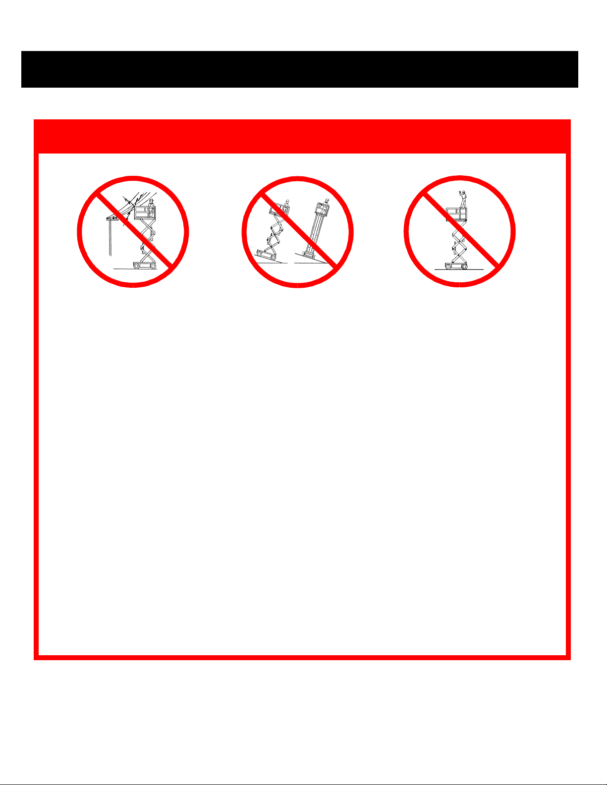
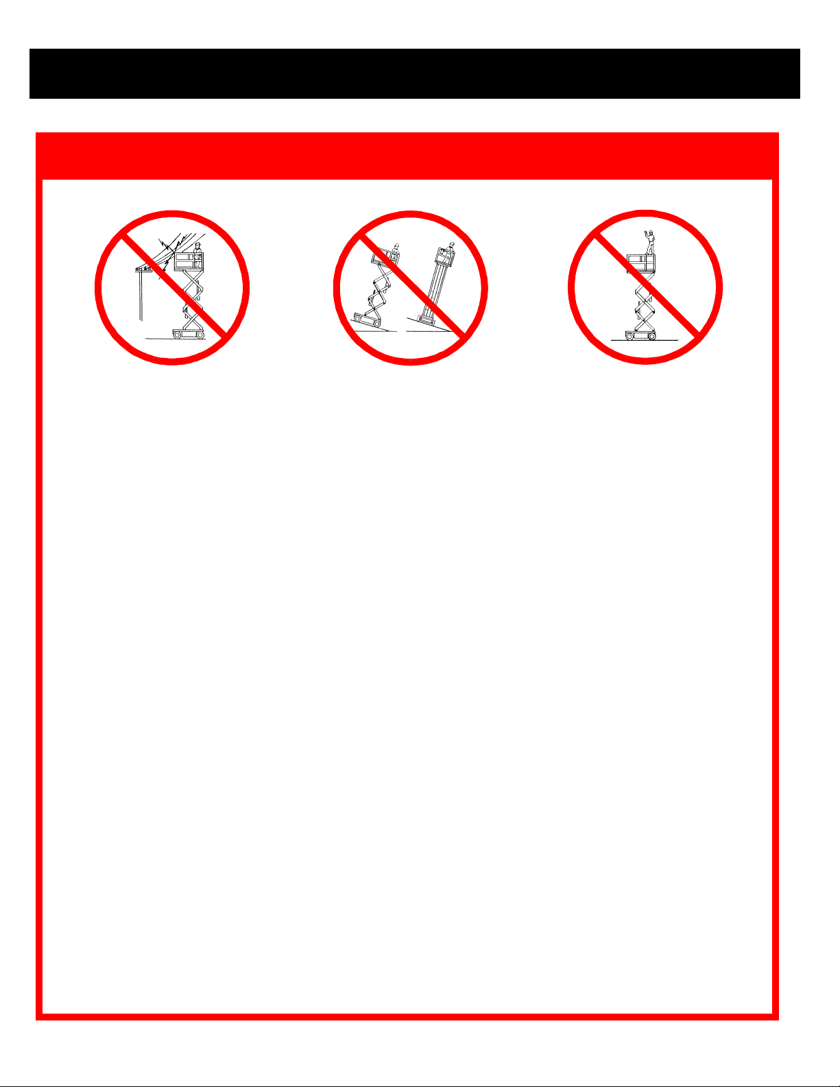
EVER
N
operate the machine within
ten feet of power lines. THIS
MACHINE IS NOT INSULATED
EVER
N
elevate or drive elevated
on uneven slopes or soft ground
.
or elevate the platform unless the
EVER
N
sit, stand or climb on
guardrail or midrail.
platform is level.
EVER
N
operate the machine without first surveying the work area for surface hazards such as holes, drop-offs,
bumps and debris.
EVER
N
S
K
N
N
M
L
D
N
N
I
operate the machine if all guardrails are not properly in place and secured with all fasteners properly torqued.
ECURE
NSPECT
and lock gate after mounting platform.
EEP
all body parts clear of outriggers when extending or retracting (outrigger equipped machines only).
EVER
use ladders or scaffolding on the platform.
EVER
attach overhanging loads or increase platform size.
AINTAIN
OOK
ISTRIBUTE
EVER
EVER
tire pressure at 50 psi (LX31/41).
up, down and around for overhead obstructions and electrical conductors.
all loads evenly on the platform. See the back cover for maximum platform load.
use damaged equipment. (Contact UpRight for instructions. See toll-free phone number on back cover.)
change operating or safety systems.
the machine thoroughly for cracked welds, loose hardware, hydraulic leaks, damaged control cable, loose
wire connections and wheel bolts.
EVER
N
N
N
climb down elevating assembly with the platform elevated.
EVER
perform service on machine while platform is elevated without blocking elevating assembly.
EVER
recharge battery near sparks or open flame; batteries that are being charged emit highly explosive hydrogen
gas.
FTER USE
A
EVER
N
secure the work platform against unauthorized use by turning key switch off and removing key.
replace any component or part with anything other than original UpRight replacement parts without the man-
ufacturer's consent.
2 43
Page 3
NTRODUCTION
I
YSTEM FUNCTION INSPECTION
S
This manual covers all models of the LX Series
Work Platforms. This manual must be stored on the
machine at all times.
PRE-O
NOTE:Carefully read, understand and follow
all safety rules, operating instructions,
labels and the Scaffold Industry Association’s MANUAL OF RESPONSIBILITIES. Perform the following steps each day before
use.
1. Open modules and inspect for damage, oil leaks or
missing parts.
2. Check the hydraulic oil level sight gauge on the hydraulic tank with the platform fully lowered. Add fluid if necessary.
3. Check that fluid level in the battery is correct (see Bat-
tery Maintenance).
4. Check the engine oil level and fuel level.
5. Check that all guardrails are in place, the slide out deck
extension is secured with the pin and all fasteners are
properly tightened.
6. Check tire pressure; 50 psi (3.4 bar)
7. Carefully inspect the entire work platform for damage
such as cracked welds or structural members, loose or
missing parts, oil leaks, damaged cables or hoses,
loose connections and tire damage.
8. Move machine, if necessary, to unobstructed area to
allow for full elevation.
9. Place chassis and platform emergency stop switches in
the ON position (Figures 1 & 2) by pulling the buttons
out.
10. Verify platform/chassis switch is set to PLATFORM.
11. While the engine is cool check the engine coolant level.
DO NOT check coolant when engine or radiator
is hot, hot coolant can cause severe burns.
PERATION
!
CAUTION
AFETY INSPECTION
& S
!
!
WARNING
STAND CLEAR of the work platform while
performing the following checks.
Before operating the work platform survey the
work area for surface hazards such as holes,
drop-offs, bumps and debris.
Check in ALL directions, including above the
work platform, for obstructions and electrical
conductors.
Protect control console cable from possible
damage while performing checks.
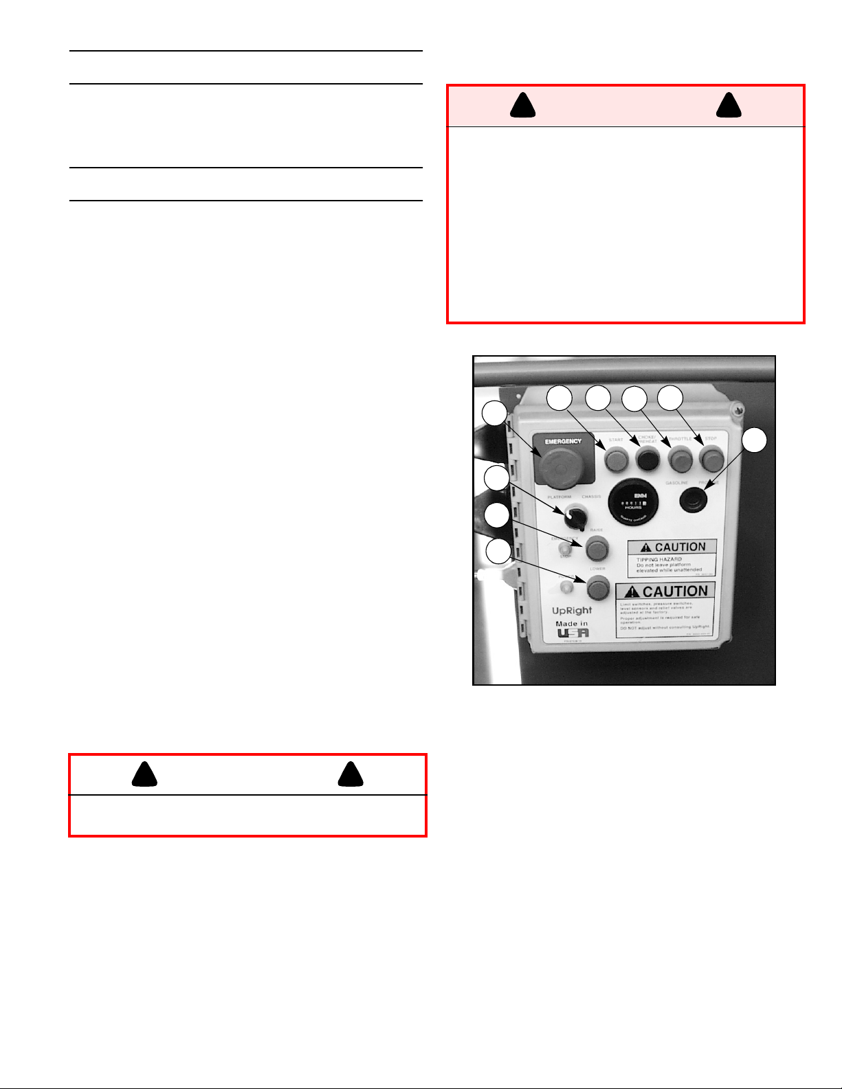
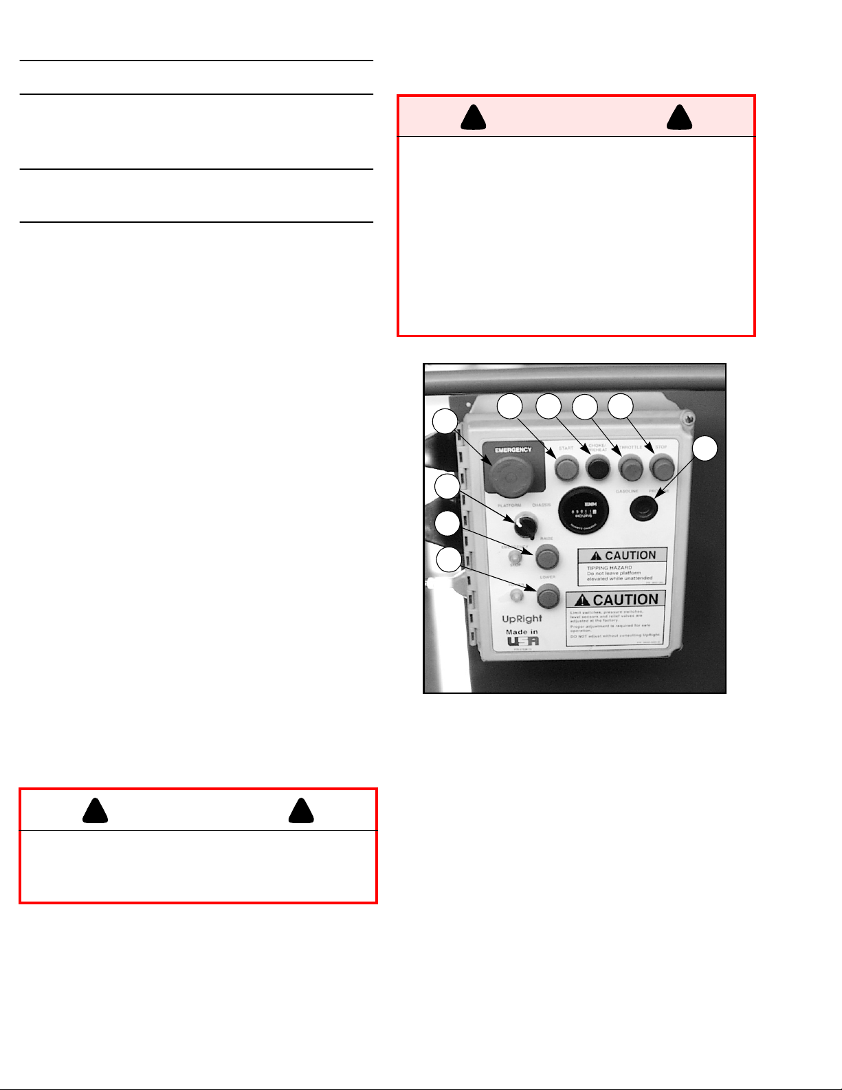
5 6 8
1
2
3
4
Figure 1: Chassis Controls
1. Emergency Stop
2. Platform/Chassis
Switch
3. Raise Button
4. Lower Button
5. Start Button
1. Unhook controller from front guardrail. Firmly grasp
controller hanger in such a manner that the interlock
lever can be depressed, while performing the following
checks from the ground.
2. Turn controller key switch clockwise to ON. Turn fully
clockwise to start engine, releasing the key once the
engine starts.
7
6. Choke Button (Dual
Fuel) or Glow Plug
Button (Diesel)
7. Throttle Button
8. Stop Button
9. Fuel Selector Switch
(Dual Fuel only)
!
9
Page 4
Note: If the engine is cold, depress the glow
plug button and hold for 6 seconds to heat
the glow plugs.
1. Position drive/lift switch to DRIVE position.
2. With the speed range switch first in HIGH TORQUE and
then in HIGH SPEED depress the interlock lever and
slowly push the control lever to FORWARD then
REVERSE positions to check for speed and directional
control. The farther you push or pull the control lever
the faster the machine will travel.
3. Push steering switch RIGHT then LEFT to check for
steering control.
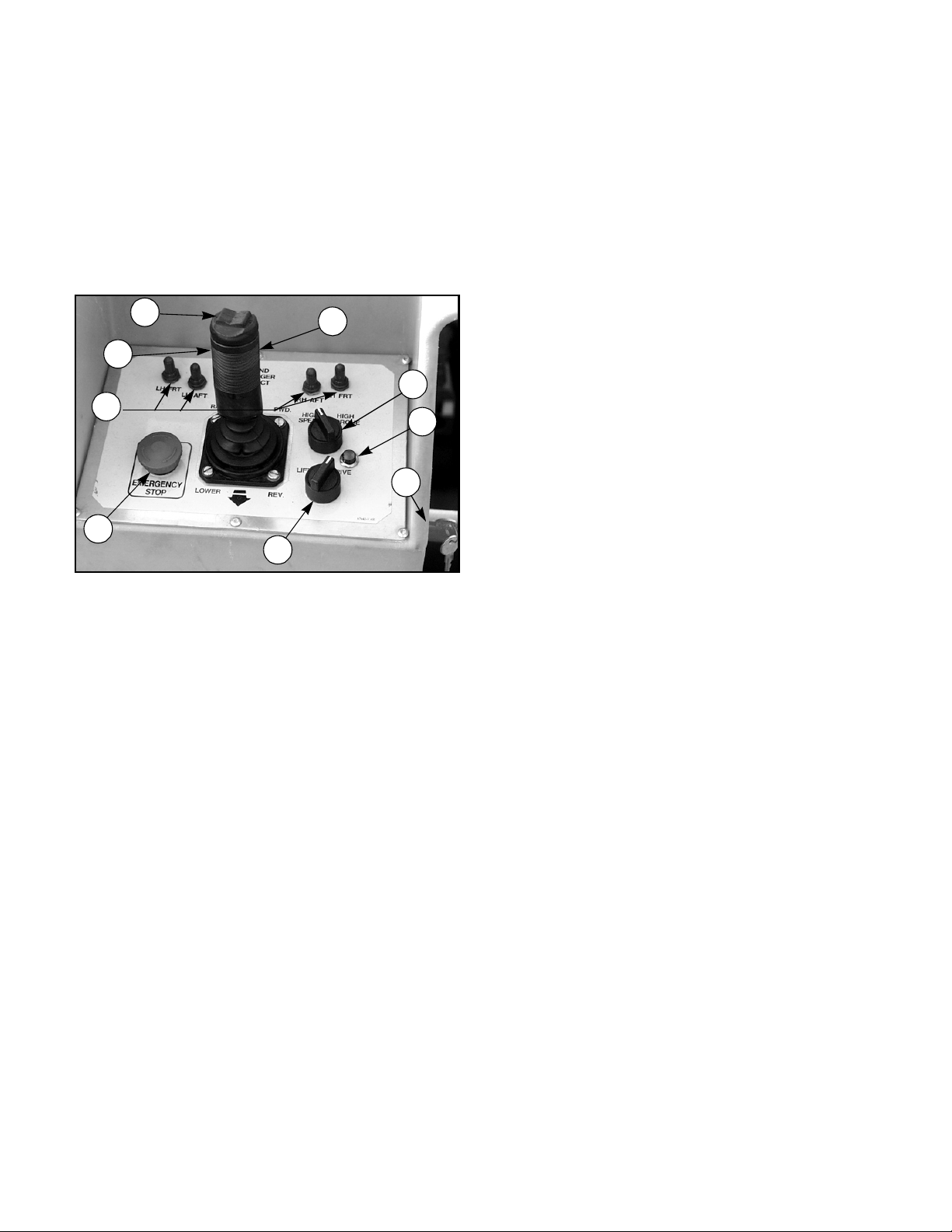
1
2
3
7
4
8
9
5
6
Figure 1: Controller
1. Steering Switch
2. Interlock Lever
Switch
3. Control Lever
4. Outrigger Switches
5. Emergency Stop
6. Drive/Lift Switch
7. Drive Speed/Torque
Selector Switch
8. Drive Enable Indicator
9. Key Switch
Switch
6. Depress the Interlock switch on the control handle and
position each Outrigger switch to the EXTEND position
to deploy all four Outriggers. Check the Drive Enable
indicator, it should be off.
7. Fully retract all Outriggers and check the Drive Enable
indicator, it should be on.
8. Rehook controller on front guardrail.
9. Turn the platform/chassis switch to CHASSIS.
10. Push the throttle button in. Push chassis raise button
to elevate platform while pushing the tilt sensor off of
level. The platform should only partially elevate and the
tilt alarm should sound. If the platform continues to
elevate and/or there is no alarm STOP and remove the
machine from service until it is repaired.
11. Release the tilt sensor and fully elevate platform.
12. Visually inspect the elevating assembly, lift cylinder,
cables and hoses for damage or erratic operation.
Check for missing or loose parts.
13. Lower the platform partially by pushing in on the chassis lower switch, and check operation of the audible
lowering alarm.
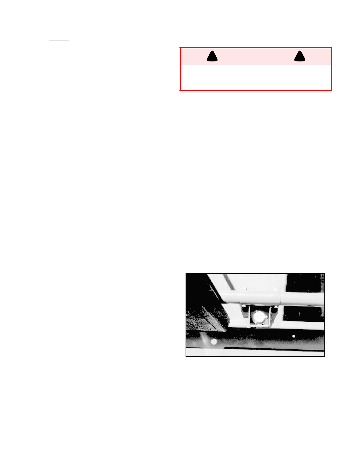
14. Open the chassis emergency lowering valve (Figure 4)
to check for proper operation by pulling and holding the
knob out. Once the platform is fully lowered, close the
valve by releasing the knob.
15. Turn the platform/chassis switch to PLATFORM.
16. Enter the platform making sure the gate is latched.
17. Position drive/lift switch to LIFT.
18. Depress the interlock lever and slowly push the control
lever to UP to raise the platform, fully actuate the control lever to check proportional lift speed. Slowly pull
control lever to DOWN position to lower platform.
Check that lowering alarm sounds.
19. Depress the interlock lever switch on the control lever
and position any Outrigger switch to the EXTEND position, Outriggers should be disabled. If an Outrigger
extends during this test STOP. Lower the platform and
remove the machine from service until it is repaired.
20. Turn controller key switch to OFF, push the emergency
stop button and dismount the platform.
21. Close and secure module covers.
4 41
Page 5
Operation
NOTE: Before operating work platform,
ensure that the pre-operation and safety
inspection has been completed, any deficiencies have been corrected and the operator has been thoroughly trained on this
machine.
RAVEL WITH PLATFORM LOWERED
T
1. Verify chassis emergency stop switch is in the ON position (turn counterclockwise), the drive enable indicator
is on, and that the platform/chassis switch is on
.
FORM
Note: If the drive enable indicator is off, verify that the platform is fully lowered and (if
so equipped) the outriggers are fully
retracted.
2. After mounting platform, close and latch gate. Check
that guardrails are in position and properly assembled
with fasteners properly torqued.
3. Check that route is clear of persons, obstructions,
holes and drop-offs and is capable of supporting the
wheel loads.
4. Check clearances above, below and to the sides of the
platform.
5. Pull controller emergency stop button out to ON position.
6. Turn controller key switch fully clockwise to start
engine, releasing the key once the engine starts.
Note: If the engine is cold, hold the glow
plug button in for 6 seconds to heat the
glow plugs.
7. Set the drive/lift speed range switch to
8. Grasp the control lever so the interlock lever is
depressed (releasing the interlock lever cuts power to
controller). Slowly push or pull the control lever to
FORWARD
tion. The farther you push or pull the control lever from
center the faster the machine will travel.
9. While moving, push the drive/lift speed range switch to
HIGH SPEED
TORQUE
areas.
or
REVERSE
for travel on level surfaces or to
for climbing grades or traveling in confined
to travel in the desired direc-
HIGH TORQUE
PLAT-
HIGH
EVELING THE PLATFORM
L
GER EQUIPPED MACHINES ONLY
!
WARNING
Never operate work platform with the parking
brakes released. Serious injury or damage
could result.
1. Look around the machine, make sure that there is nothing obstructing the outriggers, and that the surface
beneath them is suitable to support the weight of the
machine.
2. Depress the interlock lever on the control handle and
operate the outrigger switches to extend each outrigger
until it is making firm contact with the ground.
3. While observing the bubble level on the front guardrail,
(Figure 3), extend the outrigger opposite the position of
the bubble until the platform is level. For example: if the
bubble is to the front and left in the orbit, extend the
rear right outrigger. Continue to adjust until the bubble
is centered in the small circle indicating that the platform is level.
4. Outriggers must be in firm contact with the supporting
surface, observe each outrigger to verify.
TO R
1. Fully lower the platform.
2. Position each outrigger switch to
.
ETRACT THE OUTRIGGERS
the outriggers to ensure that they are fully retracted.
The drive enable indicator light will not come on until all
four outriggers are fully retracted.
UTRIG
(O
RETRACT
-
)
!
. Observe
TEERING
S
1. Push the steering switch
wheels. Observe the tires while maneuvering to insure
proper direction.
NOTE: Steering is not self-centering.
Wheels must be returned to the straight
ahead position by operating the steering
switch.
RIGHT
or
LEFT
to turn the
Figure 1: Platform Orbit Level
AISING AND LOWERING THE PLAT
R
FORM
1. Position the drive/lift switch to
2. While holding the control lever so the interlock lever is
depressed, push the control lever slowly to UP to raise
the platform. Pushing the control lever farther
increases the lift speed.
5
LIFT
.
-
Page 6
1. When the work task is completed, position the drive/lift
switch to LIFT and lower the platform by pulling back
on the control lever until the platform is fully lowered.
RAVEL WITH WORK PLATFORM ELE
T
VATED
Travel with platform elevated ONLY on firm and level
surfaces.
Note: The work platform will travel at
reduced speed when in the elevated position, and only if the front axle is parallel
with the rear axle.
1. Check that the route is clear of persons, obstructions,
holes and drop-offs, is level and capable of supporting
the wheel loads.
2. Check clearances above, below and to the sides of platform.
3. Position the drive/lift switch to the DRIVE position.
4. Push the control lever to FORWARD or REVERSE for
the desired direction of travel.
Note: Machine will not drive while elevated
above 8 meters (26 ft. 2 in.).
Note:If the machine quits driving and the tilt
alarm sounds, immediately lower the platform and move the machine to a level location before re-elevating the platform.
MERGENCY LOWERING
E
The emergency lowering control is located
at the rear of the machine at the base of the
scissor assembly (Figure 4).
1. Open the emergency lowering valve by pulling on the
knob and holding it.
2. Once the platform is fully lowered, release the knob to
close the valve.
-
FTER USE EACH DAY
A
1. Ensure that the platform is fully lowered.
2. Park the machine on level ground, preferably under
cover, secure against vandals, children or unauthorized
operation.
3. Turn the key switch to OFF and remove the key to prevent unauthorized operation.
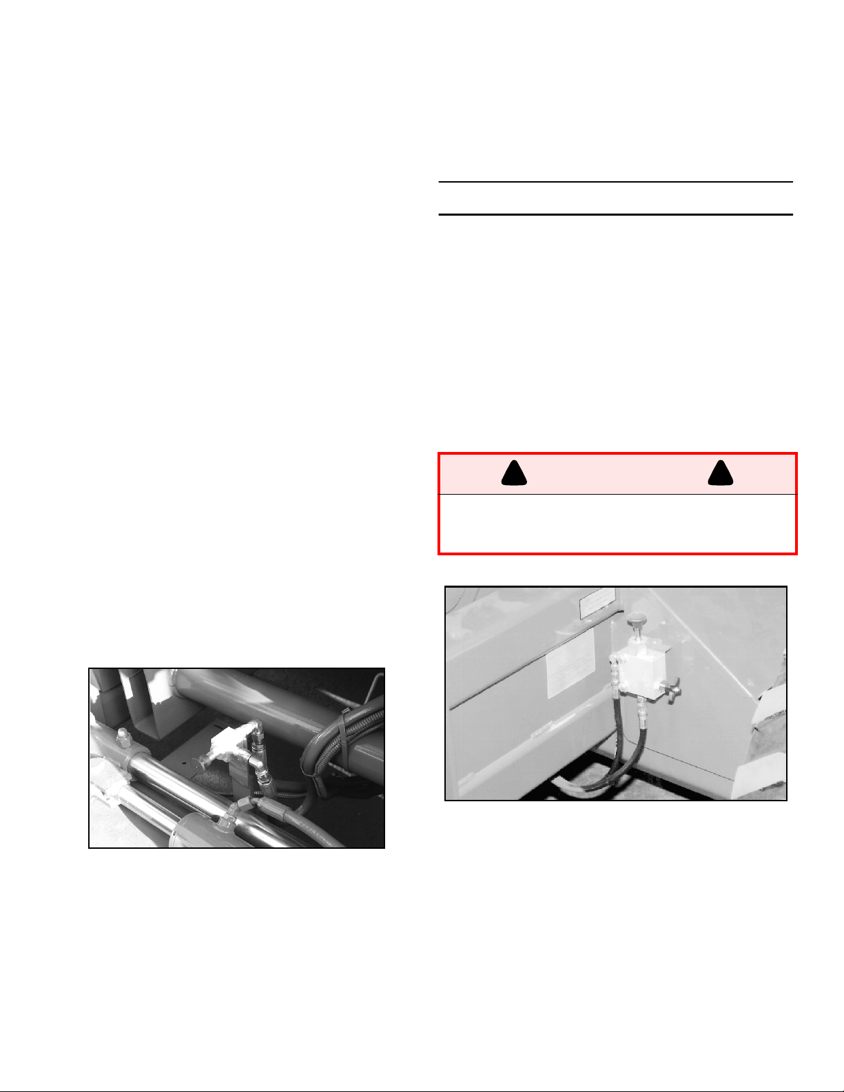
ARKING BRAKE RELEASE
P
Perform the following only when the machine will not
operate under its own power and it is necessary to
move the machine or when winching onto a trailer to
transport.
1. Close the needle valve by turning the knob clockwise.
2. Pump the brake release pump until the parking brakes
release and the wheels can be turned.
3. The machine will now roll when pushed or pulled.
4. Be sure to open the needle valve and verify that the
parking brakes have engaged before the machine is
operated.
!
WARNING
Never operate work platform with the parking
brakes released. Serious injury or damage
could result.
(F
IGURE
!
5)
Figure 1: Emergency Lowering Valve
Figure 2: Parking Brake Release Pump
6
Page 7
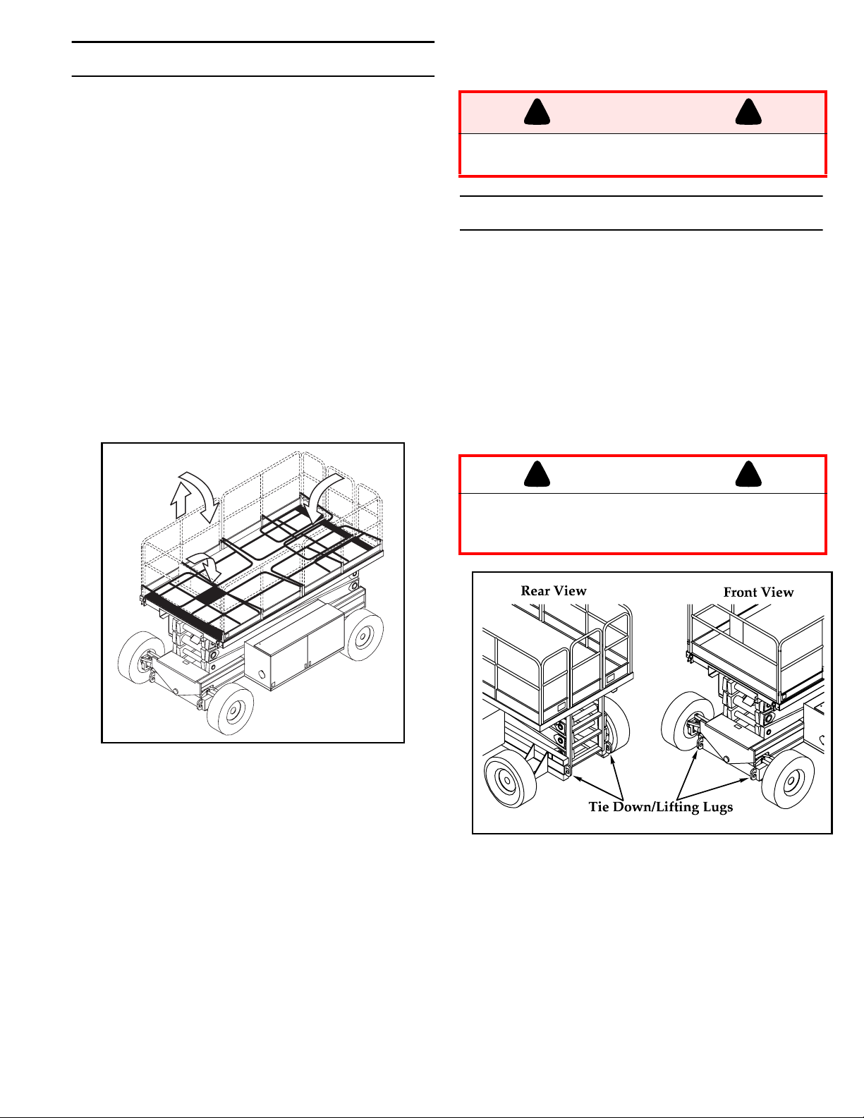
OLD DOWN GUARDRAILS
F
(F
IGURE
6)
6. Before operating work platform, check that all fasteners
are in place and properly torqued.
This procedure is only for passing through doorways. Guardrails must be returned to proper position
before using the machine.
OLD DOWN PROCEDURE
F
Note:When performing the following procedures retain all fasteners.
1. Place controller on platform
2. Starting at the front of the platform, remove nuts, bolts
and washers from the top of the front guardrail. Fold
the front guardrail down onto the platform.
3. Close and latch the gate.
4. Remove nuts, bolts and washers from the top of the
rear guardrail. Fold the rear guardrail down onto the
platform being careful to keep latched at all times.
5. Remove nuts, bolts and washers from the top of the
side guardrails. Lift up and fold one side guardrail in so
it rests on the deck. Repeat with other side guardrails.
!
WARNING
Before operating machine, guardrails must be
securely fastened in their proper position.
RANSPORTING WORK PLATFORM
T
BY C
1. Secure straps to chassis tie down/lifting lugs only (Fig-
BY T
1. Maneuver the work platform into transport position and
2. Secure the work platform to the transport vehicle with
RANE
ure 7).
RUCK
chock wheels.
chains or straps of adequate load capacity attached to
the chassis tie down/lifting lugs.
!
CAUTION
Overtightening of chains or straps through tie
down lugs may result in damage to work
platform.
!
!
Figure 1: Fold Down Guardrails
RECTION PROCEDURE
E
1. Raise side guardrails making sure each is pushed down
to secure the guardrail in the vertical position.
2. Install bolts, washers and nuts between the side guardrails, tighten securely.
3. Raise rear guardrail assembly, aligning holes and install
bolts, washers and nuts. Tighten securely.
4. Raise front guardrail, aligning holes and install bolts,
washer and nuts. Tighten securely.
5. Hang controller from front guardrail.
Figure 2: Transporting Work Platform
REPARATION FOR SHIPMENT
P
1. Grease all the grease fittings.
2. Fully lower the platform.
3. Disconnect the battery negative (-) lead from the battery terminal.
4. Band the controller to the front guardrail.
5. Band the elevating linkage to the frame.
Page 8
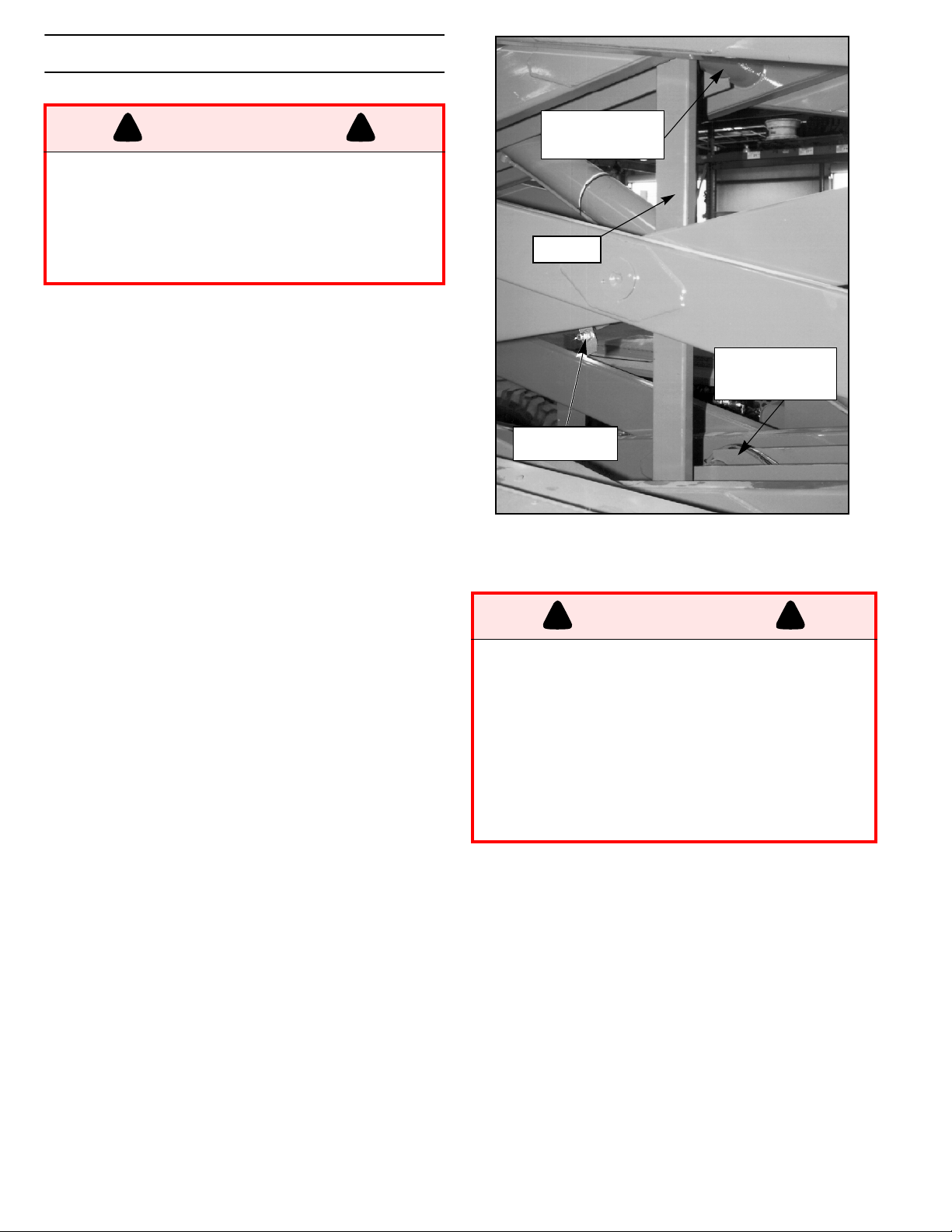
M
AINTENANCE
*
)
!
WARNING
Never perform service on the work platform in
the elevating assembly area while platform is
elevated without first blocking the elevating
assembly.
DO NOT stand in elevating assembly area
while deploying or storing brace.
B
LOCKING ELEVATING ASSEMBLY
!
Brace Installation
1. Park the work platform on firm level ground.
2. Verify Platform Emergency Stop Switch is ON.
3. Turn Chassis Key Switch to CHASSIS.
4. Start the engine using chassis controls.
5. Push the throttle button in, the button will stay in and
the engine speed will increase. Using the raise button,
elevate platform until the scissors brace can be rotated
to the vertical position.
6. From the left side of the machine, disengage the locking
pin securing the brace. Rotate the scissor brace counterclockwise until it is vertical and between the two
scissor center pivots.
7. Push lower button and gradually lower platform until
brace is supporting the platform.
8. Disengage throttle by pushing throttle button in again,
the button will retract and the engine will come to idle
speed.
Brace Removal
1. Using chassis controls, gradually raise platform until
the scissors brace clears the two scissor center pivots.
2. Rotate scissors brace clockwise until the locking pin
engages.
3. Push lower button to completely lower platform.
4. Make sure the throttle button is disengaged and platform/chassis switch is on PLATFORM.
Upper Scissor
Center Pivot
Brace
Lower Scissor
Center Pivot
Locking Pin
Figure 1: Blocking Elevating Assembly
B
ATTERY MAINTENANCE
!
WARNING
Hazard of explosive gas mixture. Keep sparks,
flame, and smoking material away from battery.
Always wear safety glasses when working with
batteries.
Battery fluid is highly corrosive. Thoroughly
rinse away any spilled fluid with clean water.
Always replace batteries with UpRight batteries
or manufacturer approved replacements
weighing 62 lbs. each.
Check battery fluid level daily, especially if work platform is being used in a warm, dry climate.
If electrolyte level is lower than 3/8 in. (10 mm)
above plates, add distilled water ONLY. Do not use of
tap water with high mineral content, it will shorten
battery life.
The battery and cables should be inspected regularly for signs of cracks in the case, electrolyte leakage and corrosion of the terminals. Inspect cables
for worn spots or breaks in the insulation and for broken cable terminals.
Refer to the Service Manual to extend battery life
and for complete service instructions.
!
8
Page 9

Preventative Maintenance Table Key
Interval
Daily=each shift or every day
50h/30d=every 50 hours or 30 days
250h/6m=every 250 hours or 6 months
1000h/2y=every 1000 hours or 2 years
Y=Yes/Acceptable
N=No/Not Acceptable
R=Repaired/Acceptable
Preventative Maintenance Report
Date: ___________________________________
Owner: _________________________________
Model No: _______________________________
Serial No: _______________________________
Serviced By: _____________________________
Service Interval: __________________________
Table 1: Preventative Maintenance Checklist
COMPONENT INSPECTION OR SERVICES INTE RVAL Y N R
Check electrolyte level 6m
Check specific gravity 6m
Ba ttery
Engine Oil
and F ilter
Engine F uel
System
Engine
Coolant
Hydraulic Oil
Hydraulic
System
Emergency
Hydraulic
System
Controller Check switch operation Da ily
Control
Platform
Deck and
Hydraulic
Clean exterior 6m
Check battery cable condition Daily
Clean terminals 6m
Check level a nd condition Daily
Check for leaks Daily
Change oil filter 100h
Check fuel level Daily
Check for leaks Daily
Replace fuel filter 6m
Check air cleaner Daily
Check coolant level (with engine cold) Daily
Replace coolant 3m
Check oil le vel Daily
Change filter 6m
Drain and replace oil 2y
Check for leaks Daily
Check hose connections 30d
Check hoses for exterior wear 30d
Operate the emergency lowering valve and check
for serviceability
Check the e xterior of the cable for pinching, binding
Cable
or wear
Check fasteners for proper torque Daily
Check welds for cracks Da ily
Rails
Check condition of deck Daily
Check for damage Daily
Tires
Check lug nuts (torque to 150 ft. lbs. [203 Nm]) 30d
Wipe clean 30d
Check for leaks at mating surfaces 30d
Pump
Check for hose fitting leaks Daily
Check mounting bolts for proper torque 30d
Daily
Daily
Table 1: Preventative Maintenance Checklist
(Continued)
COMPONENT INSPECTION OR SERVICES INTE RVAL Y N R
Drive Motors Check for operation and le aks Daily
Check for leaks Daily
Torque Hubs
Steering
System
Elevating
Assembly
Chassis
Lift Cylinder
Cylinder
Entire Unit
Labels
Check oil level 250h/6m
Change Oil after break-in 50h/30d
Change Oil 1000h/2y
Check hardware & fittings for proper torque 6m
Grease pivot pins 30d
Oil king pins 30d
Check steering cylinder for leaks 30d
Inspect for structural cracks Daily
Check pivot points for wear 30d
Check mounting pin pivot bolts for proper torque 30d
Check elevating arms for bending 6m
Check hoses for pinch or rubbing points Daily
Check component mounting for proper torque 6m
Check welds for cracks Daily
Check the cylinder rod for wear 30d
Check mounting pin pivot bolts for proper torque 30d
Check seals for leaks 30d
Inspect pivot points for wear 30d
Check fittings for proper torque 30d
Check the cylinder rod for wear 30d
Check mounting pin pivot bolts for proper torque 30d
Axle
Check seals for leaks 30d
Inspect pivot points for wear 30d
Check fittings for proper torque 30d
Check for and repair collision damage Daily
Check fasteners for proper torque 3m
Check for corrosion-remove a nd repaint 6m
Lubricate 30d
Check for peeling, missing, or unreadable labels &
rep lace
Daily
9
Page 10

PECIFICATIONS
*S
ITEM LX31 LX41 LX50
Platform Size (Inside toeboards)
Standard 3,64 m x 1,78 m [143.38 in x 70 in.] 3,64 m x 1,78 m [143.38 in. x 70 in.] 3,64 m x 1,78 m [143.38 in. x 70 in.]
Slide Out Deck Extended 4,56 m x 1,73 [179.38 in. x 68 in.] 4,56 in. x 1,73 m [179.38 in. x 68 in.] 4,56 m x 1,73 m [179.38 in. x 68 in.]
Max. Platform Capacity
Standard 907 kg [2,000 lbs.] 680 kg [1,500 lbs.] 454 kg [1,000 lbs.]
w/ Extension 907 kg [2,000 lbs.] 680 kg [1,500 lbs.] 454 kg [1,000 lbs.]
on Extension 227 kg [500 lbs.] 227 kg [500 lbs.] 227 kg [500 lbs.]
Max. No. of occupants
Standard 8 people 6 people 4
on Extension 2 people 2 people 2
Height
Working Height 11,4 m [37 ft.] 14,33 m [47 ft.] 17 m [56 ft.]
Max. Platform Height 9,45 m [31 ft.] 12,34 m [40 ft. 6 in.] 15,09 m [49 ft. 6 in.]
Min. Platform Height 1,43 m [56.25 in.] 1,66 m [65.25 in.] 1,93 m [76 in.]
Drivable Height 8 m [26 ft. 2 in.] 8 m [26 ft. 2 in.] 8 m [26 ft. 2 in.]
Dimensions
Weight, Standard 2WD: 4,264 kg [9,400 lbs.]
4WD: 4,368 kg [9,630 lbs.]
Weight, w/extension 2WD: 4,459 kg [9,830 lbs.]
4WD: 4,563 kg [10,060 lbs.]
Overall Width 2,29 m [90 in.] 2,29 m [90 in.] 2,29 m [90 in.]
Overall Height 2,53 m [99.75 in.] 2,76 m [108.75 in.] 2,76 m [108.75 in.]
Overall Le ngth, Standard 4,06 m [160 in.] 4,06 m [160 in.] 4,06 m [160 in.]
Surface Speed
Platform Lowered 0 to 5,0 km/h [0 to 3.1 mph] 0 to 5,0 km/h [0 to 3.1 mph] 0 to 5,0 km/h [0 to 3.1 mph]
Platform Raised 0 to 0,48 km/h [0 to 0.3 mph] 0 to 0,48 km/h [0 to 0.3 mph] 0 to 0,48 km/h [0 to 0.3 mph]
System V oltage 12 Volt DC 12 Volt DC 12 Volt DC
Hydraulic Tank Capacity 107,13 l [28.3 US Gallons] 107,13 l [28.3 US Gallons] 107,13 l [28.3 US Gallons]
Maximum Hydraulic System Pressure 206,8 bar [3000 psi] 206,8 bar [3000 psi] 206,8 bar [3000 psi]
Hydraulic Fluid
Normal use (>32° F [0° C]) ISO #46 ISO #46 ISO #46
Low Temp. Use (<32° F [0° C]) ISO #32 ISO #32 ISO #32
Extreme Temp. Use (<0° F [-17° C]) ISO #15 ISO #15 ISO #15
Lift System One Single Stage Lift Cylinder One Single Stage Lift C ylinder Two Single Stage Lift Cylinde rs
Lift Speed Raise: 40 sec. Lower: 60 sec. Raise: 45 sec. Lower: 65 sec. Raise: 45 sec. Lower: 65 sec.
Platform Leveling 8.5° (.3m [12 in.]) Side/Side, 6° (.3m [12 in.]
Fore/Aft
Power Source Diesel or Gasoline 20 HP Kubota, 3 Cylinde r,
Water Cooled
Drive Control Proportional Proportional Proportional
Control System Smooth one-hand Joystick Smooth one-hand Joystick Smooth one-hand Joystick
Horizontal Drive 2WD: 2 Whee l, Hyd. Motors
4WD: 4 Wheel, Hyd. Motors
Air Filled Tires 10-16.5 NHS 8 Ply, 3,4 bar [50psi.] 10-16.5 NHS 8 Ply, 3,4 bar [50psi.] 10-16.5 NHS 8 Ply, Foam Filled
Parking B rakes Two, Spring Applied, Hydraulic Release,
Multiple Disc
Turning Radius (inside) 1,22 m [48 in.] 1,22 m [48 in.] 1,22 m [48 in.]
Maximum G radeability: 2WD: 30% [16,7°] 4WD: 35% [19,2°] 2WD: 30% [16,7°] 4WD: 35% [19,2°] 2WD: 30% [16,7°] 4WD: 35% [19,2°]
Wheel Base 2,94 m [115.75 in.] 2,94 m [115.75 in.] 2,94 m [115.75 in.]
Gu ardrails 1.1 m [43.5 in.] high, Fold Down with gate. 1.1 m [43.5 in.] high, Fold Down with gate. 1.1 m [43.5 in.] high, Fold Down with gate.
Toeboard 152 mm [6 in.] High 152 mm [6 in.] High 152 mm [6 in.] High
*
2WD: 4,790 kg [10,560 lbs.]
4WD: 4,953 kg [10,920 lbs.]
2WD: 4,985 kg [10,990 lbs.]
4WD: 5,148 kg [11,350 lbs.]
8.5° (.3m [12 in.]) Side/Side, 6° (.3m [12 in.]
Fore/Aft
Diesel or Ga soline 20 HP Kubota, 3 Cylinde r,
Water Cooled
2WD: 2 Wheel, Hyd. Motors
4WD: 4 Wheel, Hyd. Motors
Two, Spring Applied, Hydraulic Release,
Multiple Disc
2WD: 5,498 kg [12,120 lbs.]
4WD: 5,661 kg [12,480 lbs.]
2WD: 5,693 kg [12,550 lbs.]
4WD: 5,856 kg [12,910 lbs.]
8.5° (.3m [12 in.]) Side/Side, 6° (.3m [12 in.]
Fore/Aft
Diesel or Ga soline 20 HP Kubota, 3 Cylinder,
Water Cooled
2WD: 2 Wheel, Hyd. Motors
4WD: 4 Wheel, Hyd. Motors
Two, Spring Applied, Hydraulic Release,
Multiple Disc
*Specifications subject to change without notice. Refer to the Service Manual for complete parts and service information
10
Page 11
Section française
Consignes de sécurité
NE
NE
JAMAIS
moins de 3 mètres (10 pi) de
lignes électriques. CETTE
MACHINE N’EST PAS ISOLÉE.
NE
JAMAIS
dangers tels que des trous, des dénivellations, des bosses ou des débris.
NE
JAMAIS
boulonnerie correctement serrée.
B
IEN FERMER
NE
PAS
stabilisateurs seulement.)
NE
JAMAIS
NE
JAMAIS
M
AINTENIR
V
ÉRIFIER
R
ÉPARTIR
dernière page de couverture.
NE
JAMAIS
d’appel gratuit en dernière page de couverture.)
NE
JAMAIS
V
ÉRIFIER
du circuit hydraulique, câble de commande endommagé ou connexion ou boulon de roue desserré.
NE
JAMAIS
NE
JAMAIS
le dispositif d’élévation.
NE
JAMAIS
émettent un gaz hydrogène hautement explosif.
A
PRÈS AVOIR UTILISÉ
afin d’empêcher l’utilisation de la plate-forme par toute personne non autorisée.
NE
JAMAIS
consentement du fabricant.
utiliser machine à
utiliser la machine sans avoir d’abord vérifié si la surface de la zone de travail ne présente pas de
utiliser la machine sans que tous les garde-corps soient parfaitement en place et assujettis toute la
et verrouiller le portillon après être monté sur la plate-forme.
s’approcher des stabilisateurs au moment d’élever ou d’abaisser la plate-forme. (Machines équipées de
utiliser d’échelle ni d’échafaudage sur la plate-forme.
attacher de charges suspendues ni accroître la taille de la plate-forme.
la pression des pneus à 3,4 bar (50 lb/po2)(LX 31/41).
en haut, en bas et autour qu’il n’existe aucun obstacle en hauteur ni conducteur électrique.
également toutes les charges sur la plate-forme. Voir la charge maximale pour la plate-forme en
utiliser d’équipement endommagé. (Contacter UpRight pour toutes instructions. Voir le numéro
modifier les systèmes de commande ou de sécurité.
complètement la machine avant de l’utiliser, en vue de soudure fissurée, boulonnerie desserrée, fuite
descendre sur le système d’élévation lorsque la plate-forme est élevée.
effectuer de travaux d’entretien sur la machine, si la plate-forme est élevée, sans tout d'abord bloquer
recharger la batterie près d’étincelles ou d’une flamme vive; les batteries en cours de charge
la plate-forme élévatrice, mettre le contacteur à clé en position d'arrêt (OFF), puis la retirer
utiliser de composant ou pièce de rechange autres que les articles UpRight d’origine sans le
JAMAIS
ni la déplacer en position élevée
sur des pentes inégales ou sur
terrain meuble, et n’élever la
plate-forme uniquement lorsquèlle se trouve sur une surface
horizontale
élever la plate-forme
.
N
E JAMAIS
grimper sur les rampes du gardecorps.
monter, s’asseoir ou
Page 12
I
NTRODUCTION
E
SSAI DE FONCTIONNEMENT DES SYSTÈMES
Ce manuel se rapporte à l’utilisation des modèles de
plates-formes élévatrices de travail série LX. On veillera à
le garder sur la machine en tout temps.
V
ÉRIFICATION PRÉLIMINAIRE ET
INSPECTION DE SÉCURITÉ
NOTA : Lire attentivement et veiller à bien
comprendre et à respecter toutes les règles
de sécurité, instructions d’utilisation, et autocollants, ainsi que le MANUEL DES RESPONSABILITÉS de la Scaffold Industry Association. Chaque jour avant d'utiliser la
machine :
1. Ouvrir les panneaux des modules et rechercher tout
dommage, fuite d’huile ou pièce manquante.
2. Vérifier le niveau indiqué par la jauge du réservoir
d’huile hydraulique avec la plate-forme complètement
abaissée. Faire l’appoint si nécessaire.
3. S'assurer que le niveau d’électrolyte de toutes les
batteries est correct. (Voir Entretien de la batterie).
4. Vérifier les niveaux d’huile moteur et de carburant.
5. Vérifier que les garde-corps sont en place, que
l’extension rétractable de la plate-forme est bloquée
avec l’axe et que toute la boulonnerie est
correctement serrée.
6. Vérifier la pression des pneus; elle doit être de
3,4 bar (50 lb/po
7. Vérifier à fond toute la plate-forme élévatrice pour
s’assurer qu’elle ne présente pas de dommages tels
que soudures ou organes de structure fissurés,
pièces desserrées ou manquantes, fuites d’huile,
câbles ou flexibles endommagés, connexions
desserrées ou pneus endommagés.
8. Au besoin, déplacer la machine jusqu’à un endroit
dégagé afin de pouvoir l’élever complètement.
9. Tirer les boutons d’arrêt d’urgence de la plate-forme
en position activée (ON) pour ces deux fonctions
(figures 1 et 2).
10. Vérifier que le sélecteur plate-forme/châssis est sur
la position plate-forme (PLATFORM).
11. Lorsque le moteur est froid, vérifier le niveau du
liquide de refroidissement.
!
2
).
ATTENTION
!
NE PAS vérifier le niveau de liquide de
refroidissement lorsque le moteur ou le
radiateur est chaud, car le liquide bouillant
pourrait causer des brûlures graves.
!
AVERTISSEMENT
SE TENIR ÉLOIGNÉ
lors des vérifications suivantes.
Avant d’utiliser la plate-forme, vérifier que la surface
de la zone de travail ne présente pas de dangers
tels que des trous, des dénivellations, des bosses
ou des débris.
Vérifier dans
dessus de la plate-forme élévatrice, qu’il n’y a ni
obstruction ni conducteur électrique.
Protéger le câble du pupitre de commande de tout
risque de dommage lors des vérifications.
TOUTES
5 6 8
de la plate-forme élévatrice
les directions, y compris au-
7
!
1
9
2
3
4
Figure 1 : Commandes du châssis
1. Arrêt d’urgence
2. Sélecteur de châssis/
plate-forme
3. Bouton d’élévation
4. Bouton d’abaissement
5. Bouton de démarrage
6. Bouton de starter
(carburation mixte) ou
bouton de bougie
incandescente (diesel)
7. Bouton d’accélérateur
8. Bouton d’arrêt
9. Sélecteur de
carburant (carburation
mixte seulement)
12
Page 13

1. Décrocher le boîtier de commande du garde-corps
avant. Saisir fermement le crochet de suspension du
boîtier de commande de manière à pouvoir abaisser
le levier d’enclenchement solidaire, tout en effectuant
les vérifications suivantes à partir du sol.
2. Tourner l’interrupteur à clé du boîtier de commande
en position marche (ON). Tourner la clé à fond vers la
droite pour lancer le moteur et la relâcher dès que le
moteur a démarré.
Nota : Si le moteur est froid, appuyer sur le
bouton de bougies incandescentes et le maintenir enfoncé pendant 6 secondes pour
chauffer les bougies.
3. Mettre le sélecteur de mode de fonctionnement en
position conduite (DRIVE).
4. Le sélecteur de gamme de vitesse étant d’abord
placé sur couple élevé (HIGH TORQUE) puis sur
haute vitesse (HIGH SPEED), appuyer sur le levier
de verrouillage et pousser le levier de commande sur
les positions marche avant (FORWARD) puis marche
arrière (REVERSE) pour vérifier les commandes de
vitesse et de sens de marche. La vitesse de
déplacement de la machine augmentera à mesure
que le levier de commande est éloigné du point mort.
5. Vérifier la commande de direction en poussant le
bouton de commande de direction d’abord vers la
DROITE, puis vers la GAUCHE.
1
2
3
7
4
8
9
5
6
Figure 1 : Boîtier de commande
1. Bouton de
commande de
direction
2. Levier d’enclenchement solidaire
3. Bouton de
commande de
stabilisateur
4. Commutateurs de
stabilisateurs
5. Bouton d’arrêt
d’urgence
6. Sélecteur de
conduite/levage
7. Sélecteur de vitesse/
couple
8. Témoin d’activation
de conduite
9. Interrupteur à clé
1. Appuyer sur le commutateur de verrouillage du levier
de commande et mettre le commutateur de chaque
stabilisateur en position extension (EXTEND) pour
déployer les quatre stabilisateurs. Vérifier que le
témoin de validation de conduite est éteint.
2. Rétracter complètement tous les stabilisateurs et
vérifier que le témoin de validation de conduite est
allumé.
3. Raccrocher le boîtier de commande sur le gardecorps avant.
4. Régler le sélecteur de châssis/plate-forme à la
position châssis (CHASSIS).
5. Enfoncer le bouton d’accélérateur. Appuyer sur le
bouton d’élévation du châssis pour élever la plateforme tout en poussant le détecteur d’inclinaison
hors de la position de mise de niveau. La plateforme ne devrait s’élever que partiellement et
l’alarme d’inclinaison devrait retentir. Si la plateforme continue à s’élever et/ou qu'aucune alarme ne
résonne, ARRÊTER et mettre la machine hors
service jusqu’à ce qu’elle ait été réparée.
6. Désengager le détecteur d’inclinaison et élever
complètement la plate-forme.
7. Inspecter le dispositif d’élévation, le vérin d’élévation,
les câbles et les flexibles en vue de dommages ou
fonctionnement irrégulier. Vérifier qu'aucune pièce
n’est desserrée ou manquante.
8. Abaisser partiellement la plate-forme au moyen du
bouton d'abaissement situé sur le tableau de
commande du châssis, puis vérifier le fonctionnement de l’alarme sonore d’abaissement.
9. Ouvrir la soupape d’abaissement d’urgence (figure 4)
pour en vérifier le fonctionnement. Pour ce faire tirer
et maintenir le bouton en position sortie. Une fois la
plate-forme complètement abaissée, relâcher le
bouton pour refermer la soupape.
10. Mettre le sélecteur de châssis/plate-forme en
position plate-forme (PLATFORM).
11. Monter sur la plate-forme et s’assurer que le loquet
du portillon est engagé.
12. Mettre le sélecteur de mode de fonctionnement en
position élévation (LIFT).
13. Appuyer sur le levier d’enclenchement solidaire et
amener progressivement le levier de commande en
position élévation (UP) pour élever la plate-forme. Ce
faisant, actionner le levier sur toute sa course afin de
vérifier la vitesse d’élévation proportionnelle. Amener
progressivement le levier de commande en position
d’abaissement (DOWN), pour abaisser la plate-
forme. S’assurer que l’alarme d’abaissement retentit.
14. Appuyer sur le commutateur de verrouillage du levier
de commande et mettre le commutateur de chaque
stabilisateur en position extension (EXTEND). Les
stabilisateurs devraient être désactivés. Si un
stabilisateur se déploie au cours de ce test,
ARRÊTER. Abaisser la plate-forme et la mettre hors
service jusqu’à ce qu’elle ait été réparée.
15. Mettre le commutateur à clé du boîtier de commande
en position arrêt (OFF), appuyer sur le bouton d’arrêt
d’urgence et descendre de la plate-forme.
16. Fermer et verrouiller les couvercles des modules.
13
Page 14

U
TILISATION
NOTA : Avant d’utiliser la plate-forme élévatrice, s’assurer que les vérifications préliminaires et de sécurité ont été effectuées, que
les problèmes éventuels ont été corrigés et
que l’opérateur a reçu une formation adéquate
pour l’utilisation de cette machine.
NOTA : La direction n'est pas à centrage
automatique. Les roues doivent être remises
en position droite à l'aide du bouton de commande de direction.
M
ISE DE NIVEAU DE LA PLATE-FORME
(
MACHINES ÉQUIPÉES DE STABILISATEURS
SEULEMENT
)
D
ÉPLACEMENT AVEC LA PLATE-FORME
ABAISSÉE
1. Vérifier que le bouton d’arrêt d’urgence du châssis
est en position activée (ON) (tourné vers la gauche),
que le témoin de validation de conduite est allumé et
que le sélecteur de plate-forme/châssis est sur la
position plate-forme (PLATFORM).
Nota : Si le témoin de validation de conduite
est éteint, vérifier que la plate-forme est complètement abaissée et que les stabilisateurs
(si la machine en est équipée) sont complètement rétractés.
2. Une fois sur la plate-forme, fermer et verrouiller le
portillon. Vérifier que les garde-corps sont en place
et correctement assemblés et que la boulonnerie est
correctement serrée.
3. Vérifier que le parcours est exempt de toute
personne, obstacle, trou et dénivellation, et que le
terrain peut supporter la charge des roues.
4. Vérifier les dégagements au-dessus, au-dessous et
sur les côtés de la plate-forme.
5. Tirer l’interrupteur d'arrêt d’urgence du boîtier de
commande en position activée (ON).
6. Tourner le commutateur à clé du boîtier de
commande à fond vers la droite pour lancer le moteur
et relâcher la clé dès que le moteur a démarré.
Nota : Si le moteur est froid, appuyer sur le
bouton de bougies incandescentes et le maintenir enfoncé pendant 6 secondes pour
chauffer les bougies.
7. Régler le sélecteur de plage de vitesses de levage/
conduite sur couple élevé (HIGH TORQUE).
8. Saisir le levier de commande afin de serrer le levier
d’enclenchement solidaire (lorsque le levier
d’enclenchement solidaire est relâché l’alimentation
électrique du boîtier de commande est coupée).
Pousser ou tirer lentement le levier de commande en
marche avant (FORWARD) ou marche arrière
(REVERSE) pour se déplacer dans la direction
souhaitée. Plus le levier est éloigné de la position
centrale (neutre), plus la machine se déplace
rapidement.
9. Lors du déplacement, pousser sur le sélecteur de
gamme de vitesse d’élévation/conduite sur vitesse
élevée (HIGH SPEED) pour se déplacer sur surfaces
planes, ou sur couple élevé (HIGH TORQUE) pour
gravir des côtes ou se déplacer dans des espaces
restreints.
!
AVERTISSEMENT
Ne jamais utiliser la plate-forme lorsque les freins
de stationnement sont desserrés. Ceci présenterait
des risques de blessures graves ou mortelles.
1. Regarder autour de la machine, s'assurer que rien ne
gène l'extension des stabilisateurs et que la surface
sur laquelle ils s'appuient peut supporter le poids de
la machine.
2. Appuyer sur le levier de verrouillage de la manette de
commande et actionner les commutateurs des
stabilisateurs pour les étendre, jusqu’à ce qu'ils
s’appuient fermement sur le sol.
3. Tout en observant le niveau à bulle du garde-corps
avant (figure 3), étendre le stabilisateur du côté
opposé à la position de la bulle, jusqu'à ce que la
plate-forme soit de niveau. Par exemple, si la bulle se
trouve à l’avant et sur la gauche de l’orbite, étendre le
stabilisateur arrière droit. Continuer d’ajuster les
stabilisateurs jusqu'à ce que la bulle soit centrée
dans le petit cercle indiquant que la plate-forme est
de niveau.
4. Les stabilisateurs doivent être fermement en contact
avec la surface d’appui. Vérifier que chaque
stabilisateur s’appuie fermement sur le sol.
R
ÉTRACTION DES STABILISATEURS
1. Abaisser complètement la plate-forme.
2. Mettre chaque commutateur de stabilisateur en
position de RÉTRACTION. Vérifier que tous les
stabilisateurs sont complètement rétractés. Le
témoin de validation de conduite ne s’allume que si
les quatre stabilisateurs sont complètement
rétractés.
!
D
IRECTION
1. Pousser le bouton de commande de direction vers la
DROITE ou la GAUCHE pour braquer. Observer les
roues pour s’assurer qu’elles tournent dans la bonne
direction.
Figure 1 : Niveau d’orbite de la plate-forme
14 31
Page 15

É
LÉVATION ET ABAISSEMENT DE LA
PLATE-FORME
1. Positionner le sélecteur de levage/conduite sur
levage (LIFT).
2. Tout en maintenant le levier de commande de sorte
que le levier d’enclenchement solidaire soit serré,
pousser lentement le levier de commande d’élévation
de commande vers haut (UP) pour élever la plateforme. Plus le levier est poussé vers le haut, plus
l’élévation est rapide.
3. Une fois le travail achevé, mettre le sélecteur
d’élévation/conduite en position d’élévation (LIFT) et
abaisser la plate-forme en tirant le levier de
commande en arrière jusqu’à ce que la plate-forme
soit complètement abaissée.
D
ÉPLACEMENT AVEC LA PLATE-FORME
ÉLEVÉE
Se déplacer avec la plate-forme élevée UNIQUEMENT sur
des surfaces horizontales solides.
Nota : Lorsqu’elle est élevée, la plate-forme ne
peut se déplacer qu’à vitesse réduite et seulement si les essieux avant et arrière sont parallèles.
1. Vérifier que le parcours est exempt de toute
personne, obstacle, trou et dénivellation, et que le
terrain peut supporter la charge des roues.
2. Vérifier les dégagements au-dessus, au-dessous et
sur les côtés de la plate-forme.
3. Mettre le sélecteur d’élévation/conduite en position
conduite (DRIVE).
4. Pousser le levier de commande en marche avant
(FORWARD) ou marche arrière (REVERSE) pour se
déplacer dans la direction souhaitée.
Nota : La machine ne se déplacera pas si la
plate-forme est élevée à plus de 8 mètres
(26 pi 2 po).
Nota : Si la machine s’immobilise et l’alarme
d’inclinaison résonne, abaisser immédiatement la plate-forme et conduire la machine
jusqu’à une surface plane avant d’élever à
nouveau la plate-forme.
A
BAISSEMENT D’URGENCE
La commande d’abaissement d’urgence se trouve à
l’arrière de la machine, à la base du ciseau (figure 4).
1. Ouvrir la vanne d’abaissement d’urgence en tirant le
bouton et en le maintenant dans cette position.
2. Une fois la plate-forme abaissée à fond, relâcher le
bouton pour fermer la soupape.
Figure 1 : Vanne d’abaissement d’urgence
A
PRÈS UTILISATION, TOUS LES JOURS
1. Abaisser complètement la plate-forme.
2. Garer la machine sur une surface plane, de
préférence couverte, à l’abri des vandales, et
protégée des enfants et de toute utilisation non
autorisée.
3. Tourner le commutateur à clé sur la position d’arrêt
(OFF), puis retirer la clé afin d’empêcher l’utilisation
non autorisée.
D
ESSERRAGE DU FREIN DE STATIONNEMENT
(
FIGURE
N’effectuer les opérations suivantes que si la machine est
immobilisée et qu'il est nécessaire de la déplacer, ou pour
la hisser sur une remorque à l’aide d’un treuil, pour le
transport.
1. Fermer la vanne à pointeau en tournant le bouton
vers la droite.
2. Actionner la pompe de desserrage du frein jusqu’à ce
que le frein de stationnement se desserre et que les
roues puissent être tournées.
3. La machine peut maintenant être déplacée en la
poussant ou en la remorquant.
4. S'assurer que la vanne à pointeau est ouverte et
vérifier que les freins de stationnement sont engagés
avant d'utiliser la machine.
!
AVERTISSEMENT
Ne jamais élever ou abaisser la plate-forme lorsque
les freins de stationnement sont desserrés, ce qui
pourrait résulter en des dommages ou blessures
graves.
5)
!
15
Page 16

G
ARDE-CORPS RABATTABLES (FIGURE
6)
!
AVERTISSEMENT
!
Cette procédure ne doit être utilisée que pour franchir des
portes. Remettre les garde-corps en position correcte
avant d’utiliser la machine.
R
EPLI DES GARDE-CORPS
Nota : Conserver les pièces boulonnerie lors
des procédures suivantes.
1. Placer le boîtier de commande sur la plate-forme.
2. En commençant à l’avant de la plate-forme, enlever
les écrous, boulons et rondelles en partant du haut
du garde-corps avant. Rabattre le garde-corps avant
sur la plate-forme.
3. Fermer et verrouiller le portillon.
4. Enlever les écrous, boulons et rondelles en
commençant par le haut du garde-corps arrière.
Rabattre le garde-corps arrière sur la plate-forme en
veillant à maintenir verrouillé à tout moment.
5. Enlever les écrous, boulons et rondelles à partir du
sommet des garde-corps de côtés. Soulever et
rabattre un garde-corps latéral de manière à ce qu'il
repose sur le plancher de la plate-forme. Répéter
l’opération avec les autres garde-corps latéraux.
Avant d’utiliser la machine, les garde-corps
doivent être fermement assujettis et en position
correcte.
T
RANSPORT DE LA PLATE-FORME
PAR
GRUE
1. N’attacher les sangles que dans les anneaux
d’arrimage/levage (figure 7).
PAR
CAMION
1. Mettre la plate-forme élévatrice en position de
transport et caler les roues.
2. Arrimer la plate-forme élévatrice sur le véhicule de
transport à l’aide de chaînes et sangles d’une
capacité de charge adéquate attachées aux anneaux
d’arrimage/levage du châssis.
!
ATTENTION
!
Un serrage excessif des chaînes ou des
sangles dans les anneaux d’arrimage peut
endommager la plate-forme élévatrice.
Figure 1 : Garde-corps rabattables
P
ROCÉDURE DE MISE EN PLACE
1. Relever les garde-corps latéraux en s’assurant que
chacun d’eux est bien poussé vers le bas de façon à
être maintenu fermement en position verticale.
2. Installer les boulons, rondelles et écrous entre les
garde-corps latéraux, et serrer fermement.
3. Relever le garde-corps arrière en alignant les trous et
installer les boulons, rondelles et écrous. Serrer
fermement.
4. Relever le dispositif de garde-corps avant, aligner les
trous et installer les boulons, rondelles et écrous.
Serrer fermement.
5. Suspendre le boîtier de commande au garde-corps
avant.
6. Avant d’utiliser la plate-forme élévatrice, vérifier que
toute la boulonnerie est bien en place et
correctement serrée.
Vue de derrière
Anneaux de levage/arrimage
Figure 2 : Transport de la plate-forme élévatrice
P
RÉPARATION POUR L'EXPÉDITION
1. Lubrifier tous les graisseurs.
2. Abaisser complètement la plate-forme.
3. Débrancher le câble négatif (-) de la borne de la
batterie.
4. Attacher le boîtier de commande au garde-corps
avant.
5. Attacher le mécanisme de commande d’élévation au
Vue de devant
16 29
Page 17

E
NTRETIEN
!
AVERTISSEMENT
Ne jamais travailler sur le système d’elévation de la
plate-forme élévatrice sans l’avoir d’abord bloqué.
NE PAS se tenir à proximité du système d’élévation
pendant le déploiement ou le repli de la barre de
verrouillage.
B
LOCAGE DU SYSTÈME D'ÉLÉVATION
!
Installation de la barre de verrouillage
1. Garer la plate-forme sur une surface plane et ferme.
2. Vérifier que le bouton d’arrêt d’urgence de la plateforme est en position engagé (ON).
3. Tourner le contacteur à clé sur la position châssis
CHASSIS
(
4. Démarrer le moteur au moyen des commandes du
châssis.
5. Appuyer sur le bouton d’accélérateur. Le bouton
restera enfoncé et le régime moteur augmentera. Au
moyen du bouton d’élévation, élever la plate-forme
jusqu’à ce que la barre de verrouillage puisse être
mise à la verticale.
6. Du côté gauche de la machine, désengager l’axe de
verrouillage de la barre. Tourner la barre de
verrouillage vers la gauche jusqu’à ce qu’elle soit à la
verticale, entre les deux pivots centraux du ciseau.
7. Appuyer sur le bouton d’abaissement pour faire
descendre lentement la plate-forme jusqu’à ce
qu’elle soit soutenue par la barre de verrouillage.
8. Désengager la commande d’accélération en
appuyant de nouveau sur le bouton. Celui-ci se
rétracte et le moteur retourne au ralenti.
).
Retrait de la barre de verrouillage
1. Au moyen des commandes du châssis, élever
graduellement la plate-forme jusqu’à ce que la barre
de verrouillage passe les deux pivots centraux du
ciseau.
2. Tourner la barre vers la droite jusqu’à ce que l’axe de
verrouillage s’engage.
3. Appuyer sur le bouton d’abaissement pour abaisser
complètement la plate-forme.
4. Vérifié que le bouton d’accélérateur est désengagé
et que le commutateur plate-forme/châssis est en
position plate-forme (
PLATFORM
).
Pivot central du
ciseau du haut
Barre
Pivot central du
ciseau du bas
Axe de verrouillage
Figure 1 : Blocage du système d’élévation
E
NTRETIEN DES BATTERIES
!
AVERTISSEMENT
Risque d’émanations de gaz explosifs. Tenir les
batteries à l’écart de toute source d’étincelles,
flammes et articles de fumeur.
Ne jamais travailler sur les batteries sans lunettes
de sécurité.
L’électrolyte est extrêmement corrosif. Éliminer
soigneusement tout électrolyte répandu en rinçant à
l’eau claire.
Toujours remplacer les batteries par des batteries
UpRight ou de modèle agréé par le fabricant, d’un
poids de 28 kg (62 lb).
Vérifier le niveau d’électrolyte tous les jours, particulièrement si la machine est utilisée sous les climats chauds et
secs.
Si l’électrolyte ne recouvre pas les plaques de batterie
d’au moins 10 mm (3/8 po), ajouter de l’eau distillée
SEULEMENT. L’usage de l’eau du robinet très calcaire
réduit la durée de vie des batteries.
La batterie et les câbles doivent être inspectés régulièrement pour détecter tout signe de fissures de la batterie, de
fuite d’électrolyte et de corrosion des bornes. Inspecter les
câbles en vue d’usure, de ruptures de l’isolation et bornes
de câbles cassées.
Voir le manuel d’entretien pour des instructions détaillées
et la prolongation de la vie utile des batteries.
!
17
Page 18

Légende du tableau d’entretiens préventifs
Périodicité
Quot. = chaque quart de travail ou chaque jour
50h/30j=toutes les 50 heures ou tous les mois
(30 jours)
250h/6m=toutes les 250 heures ou tous les 6 mois
1000h/2a=toutes les 1000 heures ou tous les 2 ans
O = Oui/Acceptable
N = Non/Inacceptable
R = Réparé/Acceptable
Rapport d'entretien préventif
Date : _______________________________________
Propriétaire : _______________________________________
No de modèle : ____________________________________
o
N
de série :________________________________________
Nom du technicien : ________________________________
Périodicité d’entretien : ______________________________
Tableau 1 :
ÉLÉMENT
Vérifier le niveau d’électrolyte 6m
Batterie
Huile et filtre
moteur
carburant
Liquide de
refroidisse-
hydraulique
hydraulique
hydraulique
de secours
Commandes Vérifier le fonctionnement de l’interrupteur Quot.
Câble de
commande
Plancher et
garde-corps
plate-forme
Pompe
hydraulique
Moteurs Vérifier le fonctionnement et s’assurer de l’absence
Vérifier la densité 6m
Nettoyer l’extérieur 6m
Vérifier l’état des câbles de batterie Quot.
Nettoyer les bornes 6m
Vérifier le niveau et l’état Quot.
à huile
Vérifier s’il y a des fuites Quot.
Changer le filtre à huile 100h
Vérifier le niveau de carburant Quot.
Vérifier s’il y a des fuites Quot.
Circuit
Remplacer le filtre à carburant 6m
Vérifier le filtre à air Quot.
Vérifier le niveau (moteur froid) Quot.
Remplacer le liquide de refroidissement 3m
ment
Vérifier le niveau de l’huile Quot.
Huile
Changer le filtre 6m
Vidanger et remplacer l’huile 2a
Vérifier s’il y a des fuites Quot.
Circuit
Vérifier le raccordement des tuyaux flexibles 30j
Vérifier l’usure extérieure des tuyaux flexibles 30j
Syst.
Faire fonctionner la soupape d’abaissement
d’urgence et vérifier son bon
fonctionnement
Vérifier l’extérieur du câble et rechercher tout
pincement, pliure ou usure
Vérifier le serrage des pièces de fixation Quot.
Vérifier si les soudures sont fissurées Quot.
de la
Vérifier l’état du pont Quot.
Vérifier le bon état Quot.
Pneus
Vérifier les écrous (serrer à 203 N·m [150 lb-pi]) 30j
Bien essuyer 30j
Vérifier s’il y a des fuites aux surfaces de contact 30j
Vérifier s’il y a des fuites aux raccordements Quot.
Vérifier le serrage des boulons de fixation 30j
de fuites
VÉRIFICATION OU ENTRETIEN
A EFFECTUER
Liste de contrôle des entretiens préventifs
PÉRIODICITÉ O N R
Quot.
Quot.
Quot.
ÉLÉMENT
Vérifier s’il y a des fuites Quot.
Moyeux
moteurs
Système de
direction
Dispositif
d’élévation
Châssis
Vérin de
Vérin de
Ensemble
machine
Étiquettes Vérifier que les autocollants ne sont pas
Vérifier le niveau de l’huile 250h/6m
Changer l’huile après la période de rodage 50h/30j
Vidanger l’huile 1000h/2a
Vérifier le serrage de la boulonnerie
et des raccords
Graisser les axes de pivot 30j
Huiler les axes de fusées 30j
Vérifier s’il y a des fuites au vérin de direction 30j
Vérifier si la structure présente des fissures Quot.
Vérifier l’usure des pièces aux points d’articulation 30j
Vérifier le serrage des boulons du pivot de la goupille
de fixation
Vérifier que les arbres d’élévation sont bien droits 6m
Vérifier que les tuyaux flexibles ne sont pas pincés et
n'ont pas de point de frottement
Vérifier le serrage des fixations des composants 6m
Vérifier si les soudures sont fissurées Quot.
Vérifier l’usure de la tige de vérin 30j
Vérifier le serrage des boulons du pivot de l’axe de
montage
Vérifier s’il y a des fuites aux joints 30j
levage
Vérifier l’usure des pièces aux points
d’articulation
Vérifier le serrage des raccords 30j
Vérifier l’usure de la tige de vérin 30j
Vérifier le serrage des boulons du pivot de la goupille
de fixation
l'axe
Vérifier s’il y a des fuites aux joints 30j
Vérifier l’usure des pièces aux points d’articulation 30j
Vérifier le serrage des raccords 30j
Inspecter en vue de dommages causés par une
collision et réparer
Vérifier le serrage de la boulonnerie 3m
de la
Vérifier s’il y a signe de corrosion; décaper
et repeindre
Lubrifier 30j
décollés, manquants ou illisibles
VÉRIFICATION OU ENTRETIEN
A EFFECTUER
PÉRIODICITÉ O N R
6m
30j
Quot.
30j
30j
30j
Quot.
6m
Quot.
18
Page 19

ARTICLE LX31 LX41 LX50
Taille de la plate-forme (à l'intérieur des plinthes)
Standard
Extension déployée
Capacité max. de la plate-forme
Standard
Avec extension
Sur l’extension
Nombre max. de personnes
Standard
Sur l’extension
Hauteur
Hauteur de travail
Hauteur max. de la plate-forme
Hauteur min. de la plate-forme
Hauteur max. en déplacement
Dimensions:
Poids, standard
Poids, avec extension
Largeur hors tout
Hauteur hors tout
Longueur hors tout, normale
Vitesse au sol
Plate-forme abaissée
Plate-forme élevée
Tension du circuit électrique
Capacité du réservoir hydraulique
Pression max. du circuit hydraulique
Huile hydraulique
Usage normal (>0 °C [32 °F])
Utilisation à basse temp. (<0 °C [32 °F])
Utilisation à basse temp. (<-17 °C [0 °F])
Système d’élévation
Vitesse d’élévation
Mise de niveau de la plate-forme
Moteur
Commande de déplacement
Système de commande
Déplacement horizontal
Pneus gonflés à l’air
Frein de stationnement
Rayon de braquage (intérieur)
Pente franchissable
Empattement
Garde-corps
Plinthe
*Caractéristiques
3,64 m x 1,78 m [143,38 po x 70 po] 3,64 m x 1,78 m [143,38 po x 70 po] 3,64 m x 1,78 m [143,38 po x 70 po]
4,56 m x 1,73 m [179,38 po x 68 po] 4,56 m x 1,73 m [179,38 po x 68 po] 4,56 m x 1,73 m [179,38 po x 68 po]
907 kg [2000 lb] 680 kg [1500 lb] 454 kg [1000 lb]
907 kg [2000 lb] 680 kg [1500 lb] 454 kg [1000 lb]
227 kg [500 lb] 227 kg [500 lb] 227 kg [500 lb]
8 personnes 6 personnes 4 personnes
2 personnes 2 personnes 2 personnes
11,4 m [37 pi] 14,33 m [47 pi] 17 m [56 pi]
9,45 m [31 pi] 12,34 m [40 pi 6 po] 15,09 m [49 pi 6 po]
1,43 m [56,25 pi] 1,66 m [65,25 pi] 1,93 m [76 po]
8 m [26 pi 2 po] 8 m [26 pi 2 po] 8 m [26 pi 2 po]
2X2 : 4264 kg [9400 lb]
4X4 : 4368 kg [9630 lb]
2X2 : 4459 kg [9830 lb]
4X4 : 4563 kg [10 060 lb]
2,29 m [90 po] 2,29 m [90 po] 2,29 m [90 po]
2,53 m [99,75 po] 2,76 m [108,75 po] 2,76 m [108,75 po]
4,06 m [160 po] 4,06 m [160 po] 4,06 m [160 po]
0 à 5,0 km/h [0 à 3,1 mi/h] 0 à 5,0 km/h [0 à 3,1 mi/h] 0 à 5,0 km/h [0 à 3,1 mi/h]
0 à 0,48 km/h [0 à 0,3 mi/h] 0 à 0,48 km/h [0 à 0,3 mi/h] 0 à 0,48 km/h [0 à 0,3 mi/h]
12 V CC 12 V CC 12 V CC
107,13 L [28,3 gallons US] 107,13 L [28,3 gallons US] 107,13 L [28,3 gallons US]
206,8 bar [3000 lb/po2] 206,8 bar [3000 lb/po2] 206,8 bar [3000 lb/po2]
ISO n° 46 ISO n° 46 ISO n° 46
ISO n° 32 ISO n° 32 ISO n° 32
ISO n° 15 ISO n° 15 ISO n° 15
Un vérin d’élévation à un étage Un vérin d’élévation à un étage Deux vérins d’élévation à un étage
Élévation : 40 s
Abaissement : 60 s
latérale = 8,5° (0,3 m [12 po]),
longitudinale = 6° (0,3 m [12 po])
Diesel ou essence 20 HP Kubota,
3 cylindres, refroidi par eau
Proportionnelle Proportionnelle Proportionnelle
Manche à balai muni d’un levier
d’enclenchement solidaire
2X2 : 2 roues, moteurs hyd.
4X4 : 4 roues, moteurs hyd.
8 plis NHS 10-16,5, 3,4 bar [50 lb/po2] 8 plis NHS 10-16,5, 3,4 bar [50 lb/po2]
Deux, multidisques, serrage par ressort,
desserrage hydraulique
1,22 m [48 po] 1,22 m [48 po] 1,22 m [48 po]
2X2 : 30 % [16,7°]
4X4 : 35 % [19,2°]
2,94 m [115,75 po] 2,94 m [115,75 po] 2,94 m [115,75 po]
1,1 m [43,5 po] de haut, rabattable
avec portillon
152 mm [6 po] de haut 152 mm [6 po] de haut 152 mm [6 po] de haut
2X2 : 4790 kg [10 560 lb]
4X4 : 4953 kg [10 920 lb
2X2 : 4985 kg [10 990 lb]
4X4 : 5148 kg [11 350 lb
Élévation : 45 s
Abaissement : 65 s
latérale = 8,5° (0,3 m [12 po]),
longitudinale = 6° (0,3 m [12 po])
Diesel ou essence 20 HP Kubota,
3 cylindres, refroidi par eau
Manche à balai muni d’un levier
d’enclenchement solidaire
2X2 : 2 roues, moteurs hyd.
4X4 : 4 roues, moteurs hyd.
Deux, multidisques, serrage par ressort,
desserrage hydraulique
2X2 : 30 % [16,7°]
4X4 : 35 % [19,2°]
1,1 m [43,5 po] de haut, rabattable
avec portillon
2X2 : 5498 kg [12 120 lb]
4X4 : 5661 kg [12 480 lb]
2X2 : 5693 kg [12 550 lb]
4X4 : 5856 kg [12 910 lb]
Élévation : 45 s
Abaissement : 65 s
latérale = 8,5° (0,3 m [12 po]),
longitudinale = 6° (0,3 m [12 po])
Diesel ou essence 20 HP Kubota,
3 cylindres, refroidi par eau
Manche à balai muni d’un levier
d’enclenchement solidaire
2X2 : 2 roues, moteurs hyd.
4X4 : 4 roues, moteurs hyd.
8 plis NHS 10-16,5, remplis de poly
Deux, multidisques, serrage par ressort,
desserrage hydraulique
2 roues motrices : 30 % [16,7°]
4 roues motrices : 35 % [19,2°]
1,1 m [43,5 po] de haut, rabattable
avec portillon
*Ces caractéristiques peuvent être changées sans préavis. La liste des pièces et les consignes d’entretien détaillées se trouvent
dans le Manuel d’entretien.
Page 20

Deutschsprachiger Teil
Sicherheitsregeln
Benutzen Sie die Maschine
NIEMALS im Umkreis von 3 m
(10 ft.) von Starkstromleitungen.
DIESE MASCHINE IST NICHT
ISOLIERT!
Maschine NIEMALS
abschüssige Stellen, Unebenheiten, und Abfälle zu untersuchen.
Maschine NIEMALS benutzen, solange nicht sämtliche Schutzgeländer vorschriftsmäßig angebracht und mit
allen Befestigungselementen vorschriftsmäßig festgezogen sind.
Tür nach Besteigen der Arbeitsbühne SICHERN
Alle Körperteile beim Aus- und Einfahren der Hilfsstützen von diesen FERHNALTEN (bei Maschinen mit
Hilfsstützen).
Auf der Arbeitsbühne NIEMALS Leitern oder Gerüste verwenden.
NIEMALS überhängende Lasten anbringen oder die Arbeitsbühne größenmäßig erweitern.
Reifendruck von 3,4 bar (50 psi)
Durch
oder elektrischen Leitungen vorhanden sind.
Alle Lasten gleichmäßig auf der Arbeitsbühne
der Arbeitsbühne.
NIEMALS beschädigte Geräte benutzen. (Wenden Sie sich bezüglich Anleitungen an UpRight. Die gebührenfreie Rufnummer befindet sich auf der Rückseite.)
NIEMALS irgendwelche Betriebs- oder Sicherheitseinrichtungen ändern.
Maschine gründlich auf gerissene Schweißnähte, lose Metallteile, Hydrauliklecks, beschädigte Steuerkabel, lose
Kabelanschlüsse und Radbolzen UNTERSUCHEN.
Bei angehobener Arbeitsbühne NIEMALS am Hubgestell herabklettern.
An der Maschine NIEMALS Wartungsarbeiten durchführen, wenn die Arbeitsbühne hochgefahren ist, ohne das
Hubgestell zu blockieren.
Batterie NIEMALS in der Nähe von Funken oder offenen Flammen nachladen; Batterien erzeugen beim Laden
ein hochexplosives Wasserstoffgas.
Arbeitsbühne NACH GEBRAUCH vor unbefugter Benutzung sichern, indem der Schlüsselschalter ausge-
schaltet und der Schlüssel abgezogen wird.
Komponenten und Teile
UpRight-Ersatzteile auswechseln.
in Betrieb nehmen, ohne zuvor das Arbeitsgelände auf Bodengefahren, wie z.B. Löcher,
AUFRECHTERHALTEN
SICHTPRÜFUNG nach oben, unten und im Umkreis sicherstellen, daß keine hochliegenden Hindernisse
NIEMALS ohne schriftliche Genehmigung des Herstellers gegen andere als Original-
An unebenen Steigungen oder auf
weichem Boden NIEMALS
Arbeitsbühne hochfahren oder die
Maschine verfahren, und die Arbe-
itsbühne NIEMALS hochfahren,
wenn diese nicht horizontal steht.
und verriegeln.
(LX31/41).
VERTEILEN. Siehe Rückseite bezüglich maximaler Belastung
die
NIEMALS auf dem Geländer oder
der Mittelstrebe sitzen, stehen
oder diese besteigen.
20 25
Page 21

E
INLEITUNG
S
YSTEMFUNKTIONSPRÜFUNG
Dieses Handbuch gilt für alle Arbeitsbühnenmodelle der
LX-Serie. Dieses Handbuch muß ständig an der Maschine
aufbewahrt werden.
S
ICHERHEITSINSPEKTION VOR
I
NBETRIEBNAHME
ANMERKUNG: Lesen, verstehen und befolgen
Sie sorgfältig sämtliche Sicherheitsregeln,
Betriebsanleitungen und Aufkleber sowie das
PFLICHTENHANDBUCH des Verbands der
Gerüstbauer. Führen Sie täglich vor
Inbetriebnahme die nachstehenden Schritte
durch.
1. Module öffnen und auf Beschädigung, Öllecks und
fehlende Teile prüfen.
2. Hydraulikölstand am Schauglas des Hydrauliktanks
bei völlig abgesenkter Arbeitsbühne prüfen. Bei
Bedarf Flüssigkeit nachfüllen.
3. Nachprüfen, ob der Batterieflüssigkeitsstand stimmt
(siehe Batteriewartung).
4. Füllstand von Motoröl und Kraftstoff überprüfen.
5. Nachprüfen, ob alle Schutzgeländer angebracht sind,
die Deckverlängerung durch den Bolzen gesichert ist
und alle Befestigungselemente vorschriftsmäßig
angezogen sind.
6. Reifendruck prüfen: 3,4 bar (50 psi)
7. Die gesamte Arbeitsbühne gründlich auf Schäden,
wie z.B. gerissene Schweißnähte oder Strukturteile,
lose oder fehlende Teile, Öllecks, beschädigte Kabel
und Schläuche, lose Anschlüsse und beschädigte
Reifen untersuchen.
8. Maschine, wenn erforderlich, an eine freie Stelle
bringen, die das vollständige Hochfahren ermöglicht.
9. Notaustaster des Fahrwerks und der Plattform durch
Herausziehen der Knöpfe auf Ein (ON) (Abbildung 1
und 2) stellen.
10. Sicherstellen, daß der Plattform-Fahrwerks-Schalter
auf Plattform (
11. Bei kaltem Motor den Füllstand des Motorkühlmittels
prüfen.
!
Kühlmittel NICHT bei heißem Motor oder Kühler
prüfen, da heißes Kühlmittel schwere
Verbrennungen verursachen kann.
PLATFORM
) steht.
VO RSICH T
!
!
WA RN U N G
Bei Durchführung der nachstehenden Prüfungen ist
von der Arbeitsbühne ABSTAND ZU HALTEN.
Untersuchen Sie vor Inbetriebnahme der
Arbeitsbühne den Arbeitsbereich auf FahrbahnGefahrenstellen, wie z.B. Löcher, Abhänge,
Unebenheiten und Abfall.
Prüfen Sie die GESAMTE Umgebung,
einschließlich oberhalb der Arbeitsbühne, auf
Hindernisse und elektrische Leitungen.
Schützen Sie bei den Überprüfungen das
Steuerpultkabel gegen mögliche Beschädigung.
5 6 8
7
!
1
9
2
3
4
Abbildung 1: Fahrwerks-Steuerorgane
1. Notaus
2. Plattform-/Fahrwerk-/
Schalter
3. Hochfahrknopf
4. Absenkknopf
5. Startknopf
1. Steuergerät am vorderen Schutzgeländer
aushängen. Steuergerätaufhänger so greifen, daß
sich der Sperrhebel drücken läßt, während die
nachstehenden Überprüfungen vom Boden aus
vorgenommen werden.
2. Schlüsselschalter des Steuergeräts nach rechts auf
Ein (ON) drehen. Zum Starten des Motors den
Schlüssel ganz nach rechts drehen; loslassen,
sobald der Motor anspringt.
Anmerkung: Bei kaltem Motor den
Vorglühknopf sechs Sekunden lang drücken,
um die Glühkerzen vorzuwärmen.
6. Choke-Knopf
(Zweistoffbetrieb) oder
Vorglühknopf (Diesel)
7. Drosselklappenknopf
8. Abstellknopf
9. Kraftstoff-Wählschalter
(nur bei Zweistoffbetrieb)
Page 22

1. Den Schalter Fahren / Heben (Drive/Lift) auf Fahren
(DRIVE) stellen.
2. Sperrhebel zunächst bei Gangwähl-Schalterstellung
auf hohes Drehmoment (HIGH TORQUE), und
danach auf Schneller Gang (HIGH SPEED), drücken
und den Steuerhebel langsam erst auf Vorwärts
(FORWARD), dann auf Rückwärts (REVERSE)
stellen, um die Funktion der Geschwindigkeits- und
Richtungssteuerung zu prüfen. Je weiter der
Steuerknüppel gedrückt bzw. gezogen wird, desto
schneller fährt die Maschine.
3. Den Lenkschalter auf Rechts (RIGHT), dann auf
Links (LEFT) drücken, um die Lenkfunktion zu
prüfen.
1
2
3
7
4
8
9
5
6
Abbildung 1: Steuergerät
1. Lenkungsschalter
2. Sperrhebelschalter
3. Steuerhebel
4. Hilfsstützenschalter
5. Notausschalter
6. Fahr-Hub-Schalter
7. Geschwindigkeits-/
DrehmomentWählschalter
8. Fahrfunktionsleuchte
9. Schlüsselschalter
12. Hubgestell, Hubzylinder, Kabel und Schläuche visuell
auf Beschädigungen und sprunghafte Bewegungen
untersuchen. Gerät auf fehlende oder lose Teile
untersuchen.
13. Arbeitsbühne durch Hineindrücken des Knopfes
Senken am Fahrwerk zum Teil absenken und die
Funktion der akustischen Senkwarnung prüfen.
14. Das Fahrwerk-Notsenkventil “emergency lowering”
(Abbildung 4) durch Herausziehen und Halten des
Knopfes öffnen, um die einwandfreie Funktion des
Ventils zu prüfen. Ventil nach völligem Absenken der
Arbeitsbühne durch Loslassen des Knopfes
schließen.
15. Den Schalter Arbeitsbühne / Fahrwerk auf
Arbeitsbühne (PLATFORM) stellen.
16. Plattform betreten und sicherstellen, daß die Tür
eingeklinkt ist.
17. Den Schalter Fahren / Heben auf Heben (LIFT)
stellen.
18. Sperrhebel drücken und den Steuerhebel allmählich
auf Aufwärts (UP) schieben, um die Plattform
hochzufahren; Steuerhebel ganz betätigen, um die
proportionale Hubgeschwindigkeit zu prüfen.
Steuerhebel allmählich auf Stellung Abwärts
(DOWN) ziehen, um die Plattform abzusenken.
Nachprüfen, ob die Senkwarnung ertönt.
19. Den Sperrhebelschalter am Steuerhebel drücken
und irgendeinen Hilfsstützenschalter auf Ausfahren
(EXTEND) stellen; die Hilfsstützen müssen außer
Betrieb sein. Sollte irgendeine Hilfsstütze bei diesem
Test ausfahren, STOP! Plattform absenken und
Maschine aus dem Betrieb ziehen, bis sie repariert
ist.
20. Schlüsselschalter des Steuergeräts auf Aus (OFF)
drehen, Taster Notaustaster drücken und die
Arbeitsbühne verlassen.
21. Baugruppendeckel schließen und sichern.
B
ETRIEB
6. Den Sperrschalter am Steuerhebel drücken und die
einzelnen Hilfsstützenschalter auf Ausfahren
(EXTEND) stellen, um alle vier Hilfsstützen
auszufahren. Fahrfunktionsleuchte prüfen; sie muß
aus sein.
7. Alle Hilfsstützen vollständig einfahren und die
Fahrfunktionsleuchte prüfen; sie muß an sein.
8. Steuergerät wieder am vorderen Schutzgeländer
einhängen.
9. Den Schalter Arbeitsbühne / Fahrwerk auf Fahrwerk
(CHASSIS) drehen.
10. Drosselklappenknopf hineindrücken. FahrwerksHochfahrknopf zum Hochfahren der Arbeitsbühne
drücken und gleichzeitig den Neigungssensor aus
dem Lot drücken. Die Plattform darf sich nur teilweise
heben, und die Kippwarnung muß ertönen. Falls sich
die Arbeitsbühne weiter anhebt bzw. keine Warnung
ertönt, betätigen Sie STOP und ziehen Sie die
Maschine so lange aus dem Betrieb, bis diese
repariert ist.
11. Neigungssensor loslassen und Arbeitsbühne völlig
hochfahren.
ANMERKUNG: Vor Inbetriebnahme der
Plattform ist sicherzustellen, daß die
Sicherheitsinspektion vor Inbetriebnahme
durchgeführt wurde, etwaige Mängel behoben
sind und der Bediener an dieser Maschine
gründlich ausgebildet ist.
F
AHREN MIT GESENKTER
A
RBEITSBÜHNE
1. Nachprüfen, ob der Fahrwerks-Notaustaster auf Ein
(ON) (nach links drehen) steht, die
Fahrfunktionsleuchte an ist und der Plattform-/
Fahrwerksschalter auf Plattform (PLATFORM) steht.
Anmerkung: Sollte die Fahrfunktionsleuchte
aus sein, ist nachzuprüfen, ob die Plattform
völlig abgesenkt ist und, gegebenenfalls, die
Hilfsstützen völlig eingefahren sind.
2. Tür nach Besteigen der Arbeitsbühne schließen und
verriegeln. Nachprüfen, ob die Schutzgeländer
angebracht und einwandfrei montiert sind, wobei die
Befestigungselemente vorschriftsmäßig angezogen
sein müssen.
3. Nachprüfen, ob die Fahrbahn von Personen,
Hindernissen, Löchern und Abhängen frei und in der
Lage ist, die Radlasten aufzunehmen.
22 23
Page 23

1. Prüfen Sie nach, ob oberhalb, unterhalb und seitlich
der Arbeitsbühne ein Sicherheitsabstand besteht.
2. Steuergerät-Notaustaster auf Stellung Ein (ON)
herausziehen.
3. Steuergerät-Schlüsselschalter zum Starten des
Motors ganz nach rechts drehen; Schlüssel
loslassen, sobald der Motor anspringt.
Anmerkung: Bei kaltem Motor den
Vorglühknopf sechs Sekunden lang drücken,
um die Glühkerzen vorzuwärmen.
4. Gangwählschalter auf hohes Drehmoment (HIGH
TORQUE) stellen.
5. Steuerhebel so greifen, daß der Sperrhebel gedrückt
ist (Loslassen des Sperrhebels unterbricht die
Stromzufuhr zum Steuergerät). Den Steuerhebel
langsam auf vorwärts (FORWARD) oder rückwärts
(REVERSE) schieben bzw. ziehen, um in die
gewünschte Richtung zu fahren. Je weiter man den
Steuerhebel aus der Mittelstellung drückt oder zieht,
desto schneller fährt die Maschine.
6. Während der Fahrt schiebt man auf ebener Fahrbahn
den Gangwählschalter auf Schnellgang (HIGH
SPEED), an Steigungen oder engen Stellen jedoch
auf hohes Drehmoment (HIGH TORQUE).
L
ENKEN
1. Zum Einschlagen der Räder schiebt man den
Lenkungsschalter nach RECHTS oder LINKS.
Beobachten Sie beim Manövrieren die Räder, um die
Fahrtrichtung nachzuprüfen.
ANMERKUNG: Die Lenkung ist nicht
selbstrückstellend. Die Räder müssen durch
Betätigen des Lenkschalters wieder in
Geradeausstellung gebracht werden.
N
IVELLIEREN DER PLATTFORM (NUR
BEI MASCHINEN MIT HILFSSTÜTZEN
!
WA RN U N G
Arbeitsbühne niemals bei gelöster Feststellbremse
in Betrieb nehmen. Schwere Verletzungen oder
Schäden können die Folge sein.
1. Umgebung der Maschine überprüfen und
sicherstellen, daß den Hilfsstützen nichts im Wege
steht und die darunterliegende Bodenfläche zur
Aufnahme des Maschinengewichts geeignet ist.
2. Sperrhebel am Steuerhebel drücken und jeden
Hilfsstützenschalter zum Ausfahren der
entsprechenden Hilfsstütze so lange betätigen, bis
diese festen Kontakt mit dem Boden hat.
!
)
3. Unter Beobachtung der Libelle auf dem vorderen
Schutzgeländer (Abbildung 3) fährt man die der
Luftblasenstellung gegenüberliegende Hilfsstütze so
weit aus, bis die Plattform waagerecht steht. Wenn z.
B. die Luftblase in ihrer Kreisbahn vorn links steht,
fährt man die rechte hintere Hilfsstütze aus.
Justierung fortsetzen, bis die Blase in der Mitte des
kleineren Kreises steht und damit anzeigt, daß die
Plattform nivelliert ist.
4. Die Hilfsstützen müssen mit dem sie tragenden
Boden guten Kontakt haben, was einzeln
nachzuprüfen ist.
E
INFAHREN DER HILFSSTÜTZEN
1. Plattform vollständig absenken.
2. Alle Hilfsstützenschalter auf Einfahren (RETRACT)
stellen. Durch Beobachtung sicherstellen, daß die
Hilfsstützen völlig eingefahren sind. Die
Fahrfunktionsleuchte geht erst an, wenn alle vier
Hilfsstützen völlig eingefahren sind.
Abbildung 1: Plattformlibelle
H
EBEN UND SENKEN DER ARBEITS
-
BÜHNE
1. Fahr-Hub-Schalter auf Heben (LIFT) stellen.
2. Während man den Steuerhebel so faßt, daß der
Sperrhebel gedrückt ist, schiebt man den
Steuerhebel langsam auf aufwärts (UP), um die
Arbeitsbühne hochzufahren. Je weiter der
Steuerhebel gedrückt wird, desto höher wird die
Hubgeschwindigkeit.
3. Nach beendeter Arbeit stellt man den Fahr-HubSchalter auf Heben (LIFT) und senkt die
Arbeitsbühne dadurch ab, daß man den Steuerhebel
zurückzieht, bis die Arbeitsbühne vollständig
abgesenkt ist.
Page 24

F
AHREN MIT GEHOBENER
A
RBEITSBÜHNE
Fahren Sie mit gehobener Arbeitsbühne
ebenem Boden.
Anmerkung: Die Arbeitsbühne läßt sich zwar
in hochgefahrener Stellung langsam
verfahren, jedoch nur, wenn Vorder- und
Hinterachse parallel zueinander stehen .
1. Prüfen Sie nach, ob die Fahrstrecke von Personen,
Hindernissen, Löchern und Abhängen frei ist und die
Radlasten aufnehmen kann.
2. Prüfen Sie nach, ob oberhalb, unterhalb und seitlich
der Arbeitsbühne ein Sicherheitsabstand besteht.
3. Fahr-Hub-Schalter auf Fahren (
4. Drücken Sie den Steuerhebel auf vorwärts
FORWARD
(
gewünschte Richtung zu fahren.
Anmerkung: Die Maschine läßt sich nicht
fahren, wenn sie über 8 m (26 ft. 2 in.) hoch
ausgefahren ist.
Anmerkung: Falls die Maschine stehen bleibt
und die Kippwarnung ertönt, senken Sie
sofort die Arbeitsbühne ab und bringen Sie
die Maschine an eine ebene Stelle, bevor Sie
die Plattform wieder hochfahren.
) oder rückwärts (
NUR
DRIVE
REVERSE
) stellen.
auf festem,
), um in die
L
ÖSEN DER FESTSTELLBREMSE
(A
BBILDUNG
Die folgenden Maßnahmen sind nur durchzuführen, wenn
die Maschine nicht mit eigener Kraft fahren kann, aber
bewegt oder zum Transport mit einer Winde auf einen
Anhänger gezogen werden muß.
1. Nadelventil durch Rechtsdrehung des Knopfes
schließen.
2. Bremslösepumpe so lange betätigen, bis sich die
Feststellbremse löst und die Räder drehen lassen.
3. Die Maschine läßt sich dann durch Drücken oder
Ziehen rollen.
4. Öffnen Sie vor Inbetriebnahme der Maschine
unbedingt das Nadelventil und vergewissern Sie
sich, daß die Bremsen im Eingriff sind.
!
WA RN U N G
Arbeitsbühne niemals bei gelöster Feststellbremse
in Betrieb nehmen. Schwere Verletzungen oder
Schäden können die Folge sein.
5)
!
N
OTSENKUNG
Die Notsenkbetätigung befindet sich am Heck der
Maschine, und zwar am Fuß des Scherengestells
(Abbildung 4).
1. Das Notsenkventil öffnet man durch Hochziehen und
Festhalten des Knopfes.
2. Ventil nach völligem Absenken der Arbeitsbühne
durch Loslassen des Knopfes schließen.
Abbildung 1: Notsenkventil
N
ACH TÄGLICHEM GEBRAUCH
1. Sicherstellen, daß die Arbeitsbühne vollständig
abgesenkt ist.
2. Maschine auf ebenem Boden abstellen,
vorzugsweise überdacht, und gegen mutwillige
Beschädigung, Eingriffe durch Kinder und unbefugte
Inbetriebnahme sichern.
3. Schlüsselschalter auf Aus (
Schlüssel abziehen, um eine unbefugte
Inbetriebnahme zu verhindern.
OFF
) drehen und
Abbildung 2: Feststellbremsen-Freigabepumpe
24 21
Page 25

U
MKLAPPEN DER SCHUTZGELÄNDER
(A
BBILDUNG
Dieser Arbeitsgang ist nur für das Durchfahren von Toreinfahrten vorgesehen. Vor dem Gebrauch der Maschine
muß das Schutzgeländer wieder in die vorgeschriebene
Stellung gebracht werden.
U
MKLAPPEN
Anmerkung: Bewahren Sie bei der
Durchführung der nachstehenden Schritte
sämtliche Befestigungselemente auf.
1. Steuergerät auf die Arbeitsbühne legen.
2. Beginnend mit der Vorderseite der Plattform entfernt
man die Muttern, Schrauben und Scheiben vom
Oberteil des vorderen Geländers. Vorderes
Schutzgitter auf die Plattform herunterklappen.
3. Tür schließen und verriegeln.
4. Muttern, Schrauben und Scheiben vom Oberteil des
hinteren Geländers entfernen. Hinteres Geländer auf
die Plattform herunterklappen; dabei ist darauf zu
achten, daß es ständig verriegelt bleibt.
6)
4. Vorderes Geländer hochklappen, die Löcher zum
Fluchten bringen und Schrauben, Scheiben und
Muttern einbauen. Fest anziehen.
5. Steuerpult am vorderen Schutzgitter einhängen.
6. Vor Inbetriebnahme der Arbeitsbühne ist
nachzuprüfen, ob alle Befestigungselemente
eingebaut und vorschriftsmäßig angezogen sind.
!
WA RN U N G
Vor Inbetriebnahme der Maschine müssen die
Schutzgeländer in der vorgeschriebenen Stellung
sicher befestigt sein.
T
RANSPORT DER ARBEITSBÜHNE
D
URCH KRAN
1. Gurte nur an den Verankerungs- bzw. Hublaschen
des Fahrwerks befestigen (Abbildung 7).
D
URCH LKW
1. Arbeitsbühne in Transportstellung bringen und die
Räder mit Unterlegkeilen blockieren.
2. Arbeitsbühne am Transportfahrzeug mit Ketten oder
Gurten angemessener Stärke befestigen, die an den
Verankerungs- bzw. Hublaschen des Fahrwerks
angebracht werden.
!
Abbildung 1: Klappbares Schutzgeländer
5. Muttern, Schrauben und Scheiben vom Oberteil des
seitlichen Geländers entfernen. Eins der
Seitengeländer anheben und nach innen klappen,
bis es auf dem Deck aufliegt. Vorgang beim anderen
Seitengeländer wiederholen.
A
UFRICHTEN
1. Die seitlichen Geländer hochklappen und darauf
achten, daß jedes Geländer zur Sicherung in
vertikaler Stellung heruntergedrückt wird
2. Schrauben, Scheiben und Muttern zwischen den
seitlichen Geländerteilen einbauen und fest
anziehen.
3. Hintere Geländergruppe hochklappen, die Löcher
zum Fluchten bringen und Schrauben, Scheiben und
Muttern einbauen. Fest anziehen.
!
VO RSICH T
Ein Überspannen der durch die
Befestigungslaschen hindurchgeführten Ketten
oder Gurte kann zur Beschädigung der
Arbeitsbühne führen.
Rückansicht
Verankerungs- bzw. Hublaschen
Abbildung 2: Transportieren der Arbeitsbühne
Vorderansicht
!
Page 26

T
RANSPORTVORBEREITUNGEN
1. Sämtliche Schmiernippel fetten.
2. Plattform völlig absenken.
3. Batterieminuskabel (–) am Batteriepol abklemmen.
4. Steuerpult am vorderen Schutzgeländer festbinden.
5. Hubgestänge am Rahmen festbinden.
Oberes Scherenmittellager
W
ARTUNG
!
WARN U N G
Servicearbeiten im Hubgestellbereich der
Arbeitsbühne niemals bei hochgefahrener Plattform
vornehmen, ohne vorher das Hubgestell zu
blockieren.
NIEMALS im Bereich des Hubgestells stehen,
während die Stützstrebe eingesetzt oder verstaut
wird.
B
LOCKIEREN DES HUBGESTELLS
!
Einsetzen der Stützstrebe
1. Arbeitsbühne auf festem, waagerechtem Boden
parken.
2. Nachprüfen, ob der Plattform-Notaustaster auf Ein
(ON) steht.
3. Fahrwerks-Schlüsselschalter auf Fahrwerk
(
CHASSIS
4. Motor mit Hilfe der Fahrwerks-Steuerorgane starten.
5. Drosselklappenknopf hineindrücken; der Knopf bleibt
in dieser Stellung, und die Motordrehzahl steigt an.
Plattform mit Hilfe des Hochfahrknopfs so weit
heben, bis sich die Scherenstütze in
Senkrechtstellung schwenken läßt.
6. Sicherungsbolzen der Stütze von der linken
Maschinenseite her ausklinken. Scherenstütze nach
links schwenken, bis diese zwischen den beiden
mittleren Scherenlagern senkrecht steht.
7. Den Absenkknopf drücken und die Plattform
allmählich absenken, bis diese von der Stütze
aufgenommen wird.
8. Drosselklappe durch nochmaliges Drücken des
Knopfs schließen; der Knopf geht zurück und der
Motor fällt auf Leerlauf-Drehzahl ab.
) stellen.
Entfernen der Stütze
1. Plattform mit Hilfe der Fahrwerks-Steuerorgane
allmählich heben, bis die Scherenstütze die beiden
mittleren Scherenlager freigibt.
2. Scherenstütze nach rechts schwenken, bis der
Sperrbolzen einrastet.
3. Absenkknopf drücken und die Plattform völlig
absenken.
4. Sicherstellen, daß der Drosselklappenknopf
ausgerastet ist und der Schalter Plattform/Fahrwerk)
auf Plattform (
PLATFORM
) steht.
Stützstrebe
Unteres Scherenmittellager
Sperrbolzen
Abbildung 1: Blockieren des Hubgestells
B
ATTERIEPFLEGE
!
WA RN U N G
Gefahr durch explosives Gasgemisch. Funken,
Flammen und Rauchwaren von der Batterie
fernhalten.
Beim Umgang mit Batterien ist stets eine
Schutzbrille zu tragen.
Batterieflüssigkeit ist stark ätzend. Jede
ausgelaufene Flüssigkeit muß durch gründliches
Spülen mit reinem Wasser entfernt werden.
Batterien stets durch UpRight-Batterien oder
herstellerseitig genehmigte Ausführungen ersetzen,
die je 28 kg (62 lbs.) wiegen.
Flüssigkeitsstand der Batterie täglich kontrollieren, insbesondere, wenn die Arbeitsbühne in einem warmen,
trockenen Klima eingesetzt wird.
Liegt der Elektrolytstand weniger als 10 mm (3/8 Zoll) über
den Platten, wird NUR destilliertes Wasser hinzugegeben.
Kein Leitungswasser mit hohem Mineralanteil verwenden,
da dies die Lebensdauer der Batterie verkürzt.
Batterien und Kabel sollten regelmäßig auf Anzeichen von
Rissen im Gehäuse, Elektrolyt-Leckstellen und Korrosion
der Batteriepole untersucht werden. Kabel auf Verschleißstellen und Brüche in der Isolation sowie auf
gebrochene Klemmen untersuchen.
Bezüglich Verlängerung der Batterielebensdauer und vollständiger Serviceanleitungen siehe das Servicehandbuch.
!
26 19
Page 27

Legende zur vorbeugenden Wartung
Zeitabstände
täglich = je Schicht oder täglich
50s/30t = alle 50 Std. oder 30 Tage
250s/6m = alle 250 Std. oder 6 Monate
1000s/2j = alle 1000 Std. oder 2 Jhr.
J = Ja / Akzeptabel
N = Nein / Nicht akzeptabel
R = Repariert / Akzeptabel
Tabelle 1: Kontrolliste zur vorbeugenden Wartung
Wartungsprotokoll
Datum: ______________________________________
Eigentümer: __________________________________
Modell-Nr: ____________________________________
Serien-Nr: ____________________________________
Gewartet von: _________________________________
Wartungsabstände: _____________________________
GEGENSTAND INSPEKTION ODER WARTUNG
Elektrolytstand prüfen 6m
Spezifisches Gewicht prüfen 6m
Batterie
Motoröl und
Filter
Motor-Kraftstoff-
system
Motorkühlmittel
Hydrauliköl
Hydraulik-
system
Hydraulisches
Notsystem
Steuerpult Schalterfunktion prüfen Täglich
Steuerpult Funktion aller Betätigungsorgane prüfen Täglich
Plattformdeck
und Geländer
Reifen Auf Schäden prüfen Täglich
Hydraulikpumpe Sauberwischen 30t
Antriebsmotoren Auf Funktion und Lecks prüfen Täglich
Äußerlich reinigen 6m
Batteriekabelzustand prüfen Täglich
Batterieklemmen reinigen 6m
Stand und Zustand prüfen Täglich
Auf Lecks prüfen Täglich
Ölfilter wechseln 100s
Kraftstoffstand prüfen Täglich
Auf Lecks prüfen Täglich
Kraftstoffilter wechseln 6m
Luftfilter prüfen Täglich
Kühlmittelstand prüfen (bei kaltem Motor) Täglich
Kühlmittel wechseln 3m
Ölstand prüfen Täglich
Filter wechseln 6m
Öl ablassen und ersetzen 2j
Auf Lecks prüfen Täglich
Schlauchanschlüsse prüfen 30t
Schläuche auf äußerliche Abnutzung prüfen 30t
Notsenkventil betätigen und auf Brauchbarkeit prüfen Täglich
Befestigungselemente auf richtiges Anzugsmoment
prüfen
Schweißstellen auf Risse prüfen Täglich
Deckzustand prüfen Täglich
Radmuttern prüfen (auf 203 N·m [150 ft. lbs.] anziehen)
Anschlußflächen auf Lecks prüfen 30t
Schlauchverbindungen auf Lecks prüfen Täglich
Befestigungsschrauben auf richtiges Anzugsmoment
prüfen
ZEITABSTAND
Taglish
30t
30t
J N R
GEGENSTAND INSPEKTION ODER WARTUNG
Auf Lecks prüfen Täglich
Ölstand prüfen 250s/6m
Antriebsnaben
Lenksystem
Hubgestell
Fahrwerk
Hubzylinder
Achszylinder
Gesamteinheit
Schilder
Öl nach der Einlaufzeit wechseln 50s/30t
Öl wechseln 1000s/2j
Metallteile und Anschlüsse auf richtiges
Anzugsmoment prüfen
Lagerzapfen schmieren 30t
Achsschenkelbolzen ölen 30t
Lenkzylinder auf Lecks kontrollieren 30t
Gestell auf Risse prüfen Täglich
Lagerstellen auf Verschleiß prüfen 30t
Befestigungszapfen-Schwenkbolzen auf richtiges
Anzugsmoment prüfen
Hubarme auf Verbiegung prüfen 6m
Schläuche auf Klemm- und Reibstellen prüfen Täglich
Befestigung der Bauteile prüfen auf korrektes
Anzugsmoment.
Schweißstellen auf Risse prüfen Täglich
Kolbenstange auf Verschleiß prüfen 30t
Befestigungszapfen-Schwenkbolzen auf richtiges
Anzugsmoment prüfen
Dichtungen auf Lecks prüfen 30t
Lagerstellen auf Verschleiß prüfen 30t
Anschlüsse auf richtiges Anzugsmoment prüfen 30t
Kolbenstange auf Verschleiß prüfen 30t
Befestigungszapfen-Schwenkbolzen auf richtiges
Anzugsmoment prüfen
Dichtungen auf Lecks prüfen 30t
Lagerstellen auf Verschleiß prüfen 30t
Anschlüsse auf richtiges Anzugsmoment prüfen 30t
Auf Kollisionsschäden prüfen und reparieren Täglich
Befestigungselemente auf richtiges Anzugsmo-
ment prüfen
Auf Roststellen untersuchen, ggf. diese entfernen
und Einheit neu lackieren
Schmieren 30t
Auf Abblättern, Fehlen oder Lesbarkeit prüfen
Schilder & ersetzen
ZEITABSTAND
6m
30t
6m
30t
30t
3m
6m
Täglich
J N R
27
Page 28

*Techniche Daten
GEGENSTAND LX31 LX41 LX50
Plattformgröße (zwischen den
Fußblechen)
Standardreifen 3,64 m x 1,78 m [143,38 in. x 70 in.] 3,64 m x 1,78 m [143,38 in. x 70 in.] 3,64 m x 1,78 m [143,38 in. x 70 in.]
Ausziehdeck ausgezogen 4,56 m x 1,73 m [179,38 in. x 68 in.] 4,56 m x 1,73 m [179,38 in. x 68 in.] 4,56 m x 1,73 m [179,38 in. x 68 in.]
Max. Plattform-Tragfähigkeit
Standardreifen 907 kg [2,000 lbs.] 680 kg [1,500 lbs.] 454 kg [1,000 lbs.]
mit Verlängerung 907 kg [2,000 lbs.] 680 kg [1,500 lbs.] 454 kg [1,000 lbs.]
auf Verlängerung 227 kg [500 lbs.] 227 kg [500 lbs.] 227 kg [500 lbs.]
Max. Personenzahl
Standardreifen 8 Personen 6 Personen 4 Personen
auf Verlängerung 2 Personen 2 Personen 2 Personen
Höhe
Arbeitshöhe 11,4 m [37 ft.] 14,33 m [47 ft.] 17 m [56 ft.]
Max. Plattformhöhe 9,45 m [31 ft.] 12,34 m [40 ft. 6 in.] 15,09 m [49 ft. 6 in.]
Min. Plattformhöhe 1,43 m [56,25 in.] 1,66 m [65,25 in.] 1,93 m [76 in.]
Fahrbare Höhe 8 m [26 ft. 2 in.] 8 m [26 ft. 2 in.] 8 m [26 ft. 2 in.]
Abmessungen:
Gewicht, Standard 2 rad: 4264 kg [9400 lbs.]
Gewicht, m. Verlängerung 2 rad: 4459 kg [9830 lbs.]
Gesamtbreite 2,29 m [90 in.] 2,29 m [90 in.] 2,29 m [90 in.]
Gesamthöhe 2,53 m [99,75 in.] 2,76 m [108,75 in.] 2,76 m [108,75 in.]
Gesamtlänge, Standard 4,06 m [160 in.] 4,06 m [160 in.] 4,06 m [160 in.]
Fahrgeschwindigkeit
Plattform gesenkt 0 bis 5,0 km/h [0 bis 3,1 mph] 0 bis 5,0 km/h [0 bis 3,1 mph] 0 bis 5,0 km/h [0 bis 3,1 mph]
Plattform gehoben 0 bis 0,48 km/h [0 bis 0,3 mph] 0 bis 0,48 km/h [0 bis 0,3 mph] 0 bis 0,48 km/h [0 bis 0,3 mph]
Systemspannung
Füllmenge Hydrauliktank
Max. Hydrauliksystemdruck
Hydraulikflüssigkeit
Normalbetrieb (>0 °C [32 °F]) ISO #46 ISO #46 ISO #46
Betrieb bei Tieftemperatur (<0° C
[32° F])
Betrieb bei Extremtemperatur
(<–17 °C [0 °F])
Hubsystem
Hubgeschwindigkeit
Plattform-Nivellierung
Kraftquelle
Fahrsteuerung
Steuerhebel
Fahrantrieb
Luftreifen
Feststellbremsen
Wendekreisradius (innen)
Maximale Steigfähigkeit
Radstand
Schutzgeländer
Fußblech
4 rad: 4368 kg [9360 lbs.]
4 rad: 4563 kg [10 060 lbs.]
12 V DC 12 V DC 12 V DC
107,13 L [28,3 US-Gallonen] 107,13 L [28,3 US-Gallonen] 107,13 L [28,3 US-Gallonen]
206,8 bar [3000 psi] 206,8 bar [3000 psi] 206,8 bar [3000 psi]
ISO #32 ISO #32 ISO #32
ISO #15 ISO #15 ISO #15
Ein einstufiger Hubzylinder Ein einstufiger Hubzylinder Zwei einstufige Hubzylinder
Heben: 40 sec.
Senken: 60 sec.
8,5° (0,3 m [12 in.]) Seite/Seite, 6°
(0,3 m [12 in.]) vorn/hinten
Kubota Diesel oder Benzin, 20 PS,
3 Zylinder, wassergekühlt
Proportional Proportional Proportional
Stufenloser, einhändiger Joystick Stufenloser, einhändiger Joystick Stufenloser, einhändiger Joystick
2rad: 2 hydraulische Radmotoren
4rad: 4 hydraulische Radmotoren
10-16,5 NHS 8 PR, 3,4 bar [50 psi] 10-16,5 NHS 8 PR, 3,4 bar [50 psi] 10-16,5 NHS 8 PR, schaumstoffgefüllt
Zwei, federbetätigt, hydraulische Freigabe,
Höhe 1,1 m [43,5 in.]; umklappbar einschl. Tür Höhe 1,1 m [43,5 in.]; umklappbar einschl. Tür Höhe 1,1 m [43,5 in.]; umklappbar einschl. Tür
Mehrscheiben
1,22 m [48 in.] 1,22 m [48 in.] 1,22 m [48 in.]
2rad: 30% [16,7°]
4rad: 35% [19,2°]
2,94 m [115,75 in.] 2,94 m [115,75 in.] 2,94 m [115,75 in.]
Höhe 152 mm [6 in.] Höhe 152 mm [6 in.] Höhe 152 mm [6 in.]
* Änderung technischer Daten ohne vorherige Mitteilung vorbehalten. Bezüglich kompletter Ersatzteil- und Wartungsangaben siehe
Wartungshandbuch.
2 rad: 4790 kg [10 560 lbs.]
4 rad: 4953 kg [10 920 lbs.]
2 rad: 4985 kg [10 990 lbs.]
4 rad: 5148 kg [11 350 lbs.]
Heben: 45 sec.
Heben: 65 sec.
8,5° (0,3 m [12 in.]) Seite/Seite, 6°
(0,3 m [12 in.]) vorn/hinten
Kubota Diesel oder Benzin, 20 PS,
3 Zylinder, wassergekühlt
2rad: 2 hydraulische Radmotoren
4rad: 4 hydraulische Radmotoren
Zwei, federbetätigt, hydraulische Freigabe,
Mehrscheiben
2rad: 30% [16,7°]
4rad: 35% [19,2°]
2 rad: 5498 kg [12 120 lbs.]
4 rad: 5661 kg [12 480 lbs.]
2 rad:5693 kg [12 550 lbs.]
4 rad: 5856 kg [12 910 lbs.]
Heben: 45 sec.
Heben: 65 sec.
8,5° (0,3 m [12 in.]) Seite/Seite, 6°
(0,3 m [12 in.]) vorn/hinten
Kubota Diesel oder Benzin, 20 PS, 3 Zylinder,
Zwei, federbetätigt, hydraulische Freigabe,
wassergekühlt
2rad: 2 hydraulische Radmotoren
4rad: 4 hydraulische Radmotoren
Mehrscheiben
2rad: 30% [16,7°]
4rad: 35% [19,2°]
28
Page 29

Versión en español
Normas de seguridad
J
menos de 3 m (10 pies) de líneas
de tensión eléctrica. LA
MÁQUINA NO ESTÁ
AISLADA.
AMÁS
outilice la máquina a
J
AMÁS
eleve o conduzca con
la plataforma elevada sobre
pendientes irregulares o suelo
blando, ni eleve la plataforma a
menos que esté nivelada.
No se siente, detenga o trepe
J
AMÁS
en las barandas o guía
intermedia.
J
J
A
E
J
J
M
C
D
J
J
I
J
J
J
D
J
AMÁS
utilice la máquina sin examinar antes el área de trabajo en busca de hoyos, pendientes, escalones o
escombros.
AMÁS
utilice la máquina si todos las barandillas no están colocadas adecuadamente y aseguradas con todos los
pasadores apretados correctamente.
SEGURE
VITE
estabilizadores).
AMÁS
AMÁS
ANTENGA
ERCIÓRESE
ISTRIBUYA
máxima de la plataforma.
AMÁS
llamada gratuita en la contraportada.)
AMÁS
NSPECCIONE
hidráulicas, cable de control dañado, conexiones de cables y pernos de ruedas sueltos .
AMÁS
AMÁS
bloquear el conjunto de elevación.
AMÁS
inflamable.
ESPUÉS DE UTILIZARLA
retirando la llave.
AMÁS
y bloquee la puerta tras montar la plataforma.
tocar con el cuerpo los estabilizadores cuando se extiendan o retracten (sólo máquinas con
utilice escaleras o andamios sobre la plataforma.
coloque cargas que sobresalgan o incremente el tamaño de la plataforma.
la presión de los neumáticos a 3,4 bar (50 psi) (LX31/41).
,
mirando en todas direcciones, de que no existen obstrucciones elevadas o conductores eléctricos.
todas las cargas en forma pareja sobre la plataforma. Vea la contraportada para conocer la carga
utilice equipo dañado. (Póngase en contacto con UpRight para obtener instrucciones. Vea el teléfono de
cambie los sistemas operativos o de seguridad.
la máquina completamente en busca de soldaduras agrietadas, tornillería suelta, pérdidas
descienda del conjunto de elevación con la plataforma elevada.
realice servicios de mantenimiento en la máquina mientras que la plataforma se encuentre elevada sin
recargue la batería cerca de chispas o llamas vivas, las baterías en carga emiten gas hidrógeno altamente
,
proteja la plataforma de trabajo del uso no autorizado desconectando el interruptor y
sustituya componentes o partes con repuestos no originales sin el consentimiento del fabricante.
Page 30

I
NTRODUCCIÓN
Este manual afecta a todos los modelos de la serie LX de
plataformas de trabajo. El manual debe guardarse siempre en la máquina.
I
NSPECCIÓN DE PRE-OPERACIÓN Y DE
SEGURIDAD
NOTA: Lea con detenimiento, comprenda y
respete todas las normas de seguridad,
instrucciones operativas, etiquetas y el MANUAL DE RESPONSABILIDADES de la Asociación industrial Scaffold. Lleve a cabo lo
siguiente cada día antes de utilizar la
máquina.
1. Abra los módulos e inspeccione posibles daños, pérdidas de aceite o piezas que falten.
2. Compruebe el indicador de nivel de aceite hidráulico
del depósito hidráulico con la plataforma totalmente
bajada. Agregue fluido si fuera necesario.
3. Verifique que el fluido de todas las baterías sea
correcto. (
4. Verifique los niveles del aceite lubricante y de
combustible.
5. Compruebe que las barandillas están en su lugar, la
extensión del compartimento deslizante está fijada
con el pasador y que todas las abrazaderas están
debidamente apretadas.
6. Verifique que la presión de los neumáticos sea
3,4 bar (50 psi).
7. Inspeccione detenidamente la plataforma de trabajo
completa en busca de posibles daños, como
soldaduras o miembros estructurales agrietados,
piezas sueltas o perdidas, pérdidas de aceite, cables
o mangueras dañados, conexiones sueltas y
neumáticos dañados.
8. Desplace la máquina, si fuera necesario hasta una
zona sin obstáculos en la que se permita una
elevación completa.
9. Coloque los interruptores de parada de emergencia
del chasis y la plataforma en la posición encendido
(ON) (Figuras 1 y 2) tirando del botón.
10. Compruebe que el interruptor de plataforma/chasis
se encuentra en la posición plataforma
(PLATFORM).
11. Mientras el motor esté frío, compruebe el nivel de
refrigerante del motor.
Consultar Mantenimiento de la batería
!
PRECAUCIÓN
).
!
NO compruebe el refrigerante cuando el motor
o el radiador estén calientes, el refrigerante
caliente puede producir graves quemaduras
I
NSPECCIÓN DE LAS FUNCIONES DEL
SISTEMA
!
ADVERTENCIA
MANTÉNGASE ALEJADO de la plataforma de
trabajo mientras realiza las siquientes
comprobaciones.
Antes de utilizar la plataforma de trabajo examine el
área de trabajo en busca de hoyos, pendientes,
escalones o escombros.
Compruebe posibles obstrucciones y conductores
eléctricos en TODAS las direcciones, incluyendo
por encima de la plataforma de trabajo.
Proteja el cable de la consola de control de posibles
daños mientras realiza las comprobaciones.
5 6 8
7
!
1
2
3
4
Figura 1: Controles del chasis
1. Parada de
emergencia
2. Interruptor de la
plataforma/chasis
3. Botón de elevación
4. Botón de bajada
5. Botón de arranque
6. Botón del
estrangulador
(combustible dual) o
botón de la bujía
incandescente (diesel)
7. Botón del acelerador
8. Botón de parada
9. Selector de
combustible
(combustible doble)
9
30
Page 31

1. Desenganche el controlador de la barandilla
delantera. Sostenga con firmeza el soporte del controlador de tal manera que la palanca de enclavamiento pueda accionarse mientras se realizan las
siguientes comprobaciones desde el suelo.
2. Gire el interruptor de llave del controlador en el
sentido de las agujas del reloj a la posición
encendido (ON). Gire totalmente en el sentido de las
agujas del reloj para arrancar el motor, soltando la
llave una vez que haya arrancado éste.
Nota: Si el motor está frío, pulse el botón de la
bujía incandescente y manténgalo pulsado
durante 6 segundos para calentar las bujías
incandescentes.
3. Coloque el interruptor conducir/elevar en la posición
conducir (DRIVE).
4. Con el interruptor de rango de velocidad primero en
par alto (HIGH TORQUE) y luego en gran velocidad
(HIGH SPEED), accione la palanca de
enclavamiento y empuje lentamente la palanca de
control a las posiciones adelante (FORWARD) y
luego marcha atrás (REVERSE) para comprobar el
control de velocidad y el direccional. Cuanto más
empuje o tire de la palanca de control, más rápido se
desplazará la máquina.
5. Empuje el interruptor de dirección a la DERECHA,
luego a la IZQUIERDA para comprobar el control de
dirección.
1
2
3
7
4
8
9
5
6
Figura 1: Controlador
1. Interruptor de
dirección
2. Interruptor de la
palanca de
enclavamiento
3. Palanca de control
4. Interruptores de
soportes
5. Interruptor de parada
de emergencia
6. Pulse el interruptor de enclavamiento del mando de
control y coloque cada interruptor de soporte en la
posición extender (EXTEND) para accionar los cuatro soportes. Compruebe el indicador de conducción
permitida, que debería estar apagado.
7. Retraiga totalmente los cuatro soportes y compruebe
el Indicador de conducción permitida, que debería
estar encendido.
6. Interruptor conducir/
elevar
7. Interruptor selector
de velocidad de
conducción / Par
8. Indicador de
conducción permitida
9. Interruptor del
contacto
8. Vuelva a enganchar el controlador en la barandilla
delantera.
9. Gire el conmutador plataforma/chasis a chasis
(CHASSIS).
10. Pulse el botón del acelerador. Pulse el botón de
elevación del chasis para elevar la plataforma
mientras apaga el sensor de inclinación de su
posición de nivelado. La plataforma debería elevarse
sólo parcialmente y la alarma de inclinación sonar. Si
la plataforma continúa elevándose y/o no suena la
alarma, DETENGA la máquina y retírela del servicio
hasta que sea reparada.
11. Libere el sensor de inclinación y eleve
completamente la plataforma.
12. Inspeccione visualmente el conjunto de elevación,
cilindro de elevación, cables y mangueras por
posibles daños o funcionamiento extraño.
Compruebe piezas flojas o perdidas
13. Baje la plataforma parcialmente, empujando el botón
de bajada en el chasis y verifique el funcionamiento
de la alarma audible de bajada.
14. Abra la válvula de bajada de emergencia del chasis
(Figura 4) para verificar el funcionamiento adecuado
tirando y sosteniendo la perilla. Cuando la plataforma
esté totalmente abajo cierre la válvula soltando la
perilla.
15. Gire el conmutador plataforma/chasis a plataforma
(PLATFORM).
16. Suba a la plataforma asegurándose de que la puerta
está asegurada.
17. Coloque el interruptor conducir/elevar en elevar
(LIFT).
18. Pulse la palanca de enclavamiento y empuje
lentamente la palanca de control hacia la posición
arriba (UP) para elevar la plataforma, accione
completamente la palanca de control para
comprobar la velocidad de elevación proporcional.
Lentamente tire de la palanca de control hacia la
posición abajo (DOWN) para bajar la plataforma.
Compruebe que la alarma sonora de bajada
funciona.
19. Pulse el interruptor de la palanca de enclavamiento
del mando de control y coloque cualquier interruptor
de soporte en la posición extender (EXTEND). los
Soportes deben desactivarse. Si alguno de los
soportes se extendiera durante esta prueba
DETÉNGALA. Baje la plataforma y retire la máquina
del servicio hasta que sea reparada.
20. Gire el interruptor de llave del controlador a la
posición apagado (OFF), pulse el botón de parada
de emergencia y desmonte la plataforma.
21. Cierre y asegure las cubiertas del módulo.
F
UNCIONAMIENTO
NOTA: Antes de trabajar con la plataforma,
asegúrese de que se haya completado la
inspección de pre-operación y de seguridad,
que se haya corregido cualquier deficiencia y
que el operador conozca perfectamente el
funcionamiento de esta máquina.
Page 32

D
ESPLAZAMIENTO CON LA
PLATAFORMA BAJADA
1. Compruebe que el interruptor de parada de emergencia del chasis se encuentra en la posición encendido (ON) (gire en el sentido contrario a las agujas
del reloj), el indicador de conducción permitida está
encendido, y el interruptor de la plataforma/chasis se
encuentra en la posición plataforma (PLATFORM).
Nota: Si el indicador de conducción permitida
estuviera apagado, compruebe que la
plataforma está totalmente bajada y que los
soportes están totalmente retraídos (si estuviera equipada con ellos).
2. Tras montar la plataforma, cierre y asegure la puerta.
Compruebe que todas barandillas están en posición
aseguradas en su lugar con todos los pasadores
apretados adecuadamente.
3. Compruebe que en el recorrido no hay personas,
obstáculos, agujeros y pendientes y que puede
soportar la carga de las ruedas.
4. Compruebe las distancias de seguridad por arriba,
abajo y en los laterales de la plataforma de trabajo.
5. Tire del botón de parada de emergencia del
controlador hacia la posición de encendido (ON).
6. Gire totalmente el interruptor de llave del controlador
en el sentido de las agujas del reloj para arrancar el
motor, soltando la llave una vez que haya arrancado
éste.
Nota: Si el motor está frío, mantenga pulsado
durante 6 segundos el botón de la bujía incandescente para calentar las bujías incandescentes.
7. Coloque el interruptor de rango de velocidad de
desplazamiento/elevación en par alto (HIGH
TORQUE).
8. Sujete el mando de control de modo que la palanca
de enclavamiento esté presionada (liberar la palanca
de enclavamiento corta el suministro de energía al
controlador). Empuje o tire lentamente del mando de
control hacia adelante (FORWARD) o marcha atrás
(REVERSE) para desplazarse en la dirección
deseada. Cuanto más empuje o tire del mando de
control desde el centro, más rápido se desplazará la
máquina.
9. Mientras se desplaza pulse el interruptor de rango de
velocidad de desplazamiento/elevación hacia gran
velocidad (HIGH SPEED) para desplazarse sobre
superficies planas o hacia par alto (HIGH TORQUE)
para subir pendientes o desplazarse en áreas
cerradas.
N
IVELACIÓN DE LA PLATAFORMA
(
SÓLO MÁQUINAS EQUIPADAS CON
!
ADVERTENCIA
Jamás opere la plataforma de trabajo con los frenos
de estacionamiento sueltos. Podrían darse lugar a
lesiones o daños graves.
1. Mire alrededor de la máquina para asegurarse de
que nada obstruye a los soportes, y que la superficie
debajo de éstos es adecuada para soportar el peso
de la máquina.
2. Pulse la palanca de enclavamiento del mando de
control y accione los interruptores de soporte para
extender cada soporte hasta que haya un contacto
firme con el suelo.
3. Mientras se observa el nivel de la burbuja de la
barandilla delantera (Figura 3), extienda el soporte
en la dirección opuesta a la posición de la burbuja
hasta que la plataforma se nivele. Por ejemplo: si la
burbuja se encuentra hacia delante e izquierda en el
visor, extienda el soporte trasero derecho. Continúe
ajustando hasta que la burbuja se centre con
respecto al pequeño círculo, lo cual indica que la
plataforma está nivelada.
4. Los soportes deben entrar en contacto firme con la
superficie de apoyo. Observe los soportes para
comprobar esto.
P
ARA RETRAER LOS SOPORTES
1. Baje totalmente la plataforma.
2. Coloque todos los interruptores de soporte en la
posición retraer (RETRACT). Observe los soportes
para asegurarse de que están totalmente retraídos.
La luz del indicador de conducción permitida no se
encenderá hasta que los cuatro soportes estén
totalmente retraídos.
)
!
D
IRECCIÓN
1. Empuje el interruptor de dirección a la derecha
(RIGHT), o a la izquierda (LEFT) para girar las ruedas. Observe los neumáticos mientras se maniobra
para garantizar la dirección adecuada.
NOTA: La dirección no es autocentrante. Las
ruedas deben enderezarse nuevamente
usando el interruptor de dirección.
Figura 1: Nivel de la plataforma
32
Page 33

E
LEVACIÓN Y BAJADA DE LA
PLATAFORMA
1. Coloque el interruptor conducir/elevar en elevar
(LIFT).
2. Mientras sujeta el mando de control de modo que la
palanca de enclavamiento esté presionada, presione
el mando de control lentamente hacia arriba (UP)
para elevar la plataforma. Al alejar más el mando de
control se incrementa la velocidad de elevación.
3. Cuando la tarea haya finalizado, coloque el
interruptor conducir/elevar en elevar (LIFT) y baje la
plataforma tirando hacia atrás del mando de control
hasta que la plataforma esté completamente bajada.
D
ESPUÉS DE CADA USO DIARIO
1. Asegúrese de que la plataforma esté totalmente
abajo.
2. Estacione la máquina en un terreno nivelado,
preferentemente bajo techo, asegurada contra
vándalos, niños o usos no autorizados.
3. Gire la llave de interruptor a la posición apagado
(OFF) y saque la llave para evitar usos no
autorizados.
D
ESENGANCHE DEL FRENO DE
ESTACIONAMIENTO
(F
IGURA
5)
T
RASLADO CON LA PLATAFORMA
ELEVADA
Desplácese con la plataforma elevada, SÓLO sobre ter-
reno firme y nivelado.
Nota: La plataforma de trabajo se desplazará
a velocidad reducida cuando se encuentre en
la posición elevada y sólo si el eje delantero
está en paralelo con el eje trasero.
1. Compruebe que en el recorrido no hay personas,
obstáculos, agujeros y pendientes, que está nivelado
y que puede soportar la carga de las ruedas.
2. Compruebe las distancias de seguridad por arriba,
abajo y en los laterales de la plataforma de trabajo.
3. Coloque el interruptor conducir/elevar en la posición
conducir (DRIVE).
4. Empuje el mando de control hacia adelante
(FORWARD) o marcha atrás (REVERSE) para
desplazarse en la dirección deseada.
Nota: La máquina no se desplazará mientras
esté elevada por encima de 8 metros (26 pies,
2 pulgadas).
Nota: Si la máquina deja de desplazarse y
suena la alarma de inclinación, baje inmediatamente la plataforma y lleve la máquina a un
lugar nivelado antes de volver a elevar la
plataforma.
Realice lo siguiente sólo cuando la máquina no funcione
por sus propios medios y sea necesario mover la máquina
o cuando suba la máquina mediante un cabestrante a un
camión para su transporte.
1. Cierre la válvula de aguja girando el mando en la
dirección de las agujas del reloj.
2. Accione la bomba de liberación del freno hasta que
los frenos de estacionamiento se liberen y las ruedas
puedan girarse.
3. Ahora la máquina puede rodar cuando se empuje o
tire de ella.
4. Asegúrese de abrir la válvula de aguja y verifique
que los frenos de estacionamiento se han accionado
antes de poner en funcionamiento la máquina.
!
ADVERTENCIA
Jamás opere la plataforma de trabajo con los frenos
de estacionamiento sueltos. Podría darse lugar a
lesiones o daños graves.
!
B
AJADA DE EMERGENCIA
El control de bajada de emergencia está situado
en la parte posterior de la máquina en la base del
conjunto de tijera (Figura 4).
1. Abra la válvula de bajada de emergencia tirando del
mando y sujetándolo.
2. Cuando la plataforma esté totalmente abajo suelte el
mando para cerrar la válvula.
Figura 1: Válvula de bajada de emergencia
Figura 2: Desenganche del freno de estacionamiento
33
Page 34

P
LIEGUE DE LAS BARANDILLAS
(F
IGURA
6)
6. Antes de poner en marcha la plataforma de trabajo
compruebe que todos los pasadores están en su
lugar y apretados adecuadamente.
Este procedimiento es sólo para pasar por las portezuelas. Las barandillas deben devolverse a su posición adecuada antes de utilizar la máquina.
P
ROCEDIMIENTO PARA ABATIR
Nota: Cuando lleve a cabo los siguientes procedimientos conserve todos los pasadores.
1. Coloque el controlador en la plataforma.
2. Comenzando por la parte delantera de la plataforma,
desmonte tuercas, pernos y arandelas desde la
parte superior de la barandilla. Pliegue la barandilla
delantera sobre la plataforma.
3. Cierre y asegure la puerta.
4. Desmonte la tuercas, pernos y arandelas de la parte
superior de la barandilla trasera. Pliegue la barandilla
trasera sobre la plataforma teniendo cuidado de
mantener la puerta asegurada en todo momento.
5. Desmonte la tuercas, pernos y arandelas de la parte
superior de las barandillas laterales. Levante y
pliegue una barandilla lateral de modo que descanse
sobre el compartimento. Repita con las otras
barandillas laterales.
!
ADVERTENCIA
Antes poner en marcha la máquina, las barandillas
deben estar apretadas con firmeza en la posición
adecuada.
T
RANSPORTE DE LA PLATAFORMA
!
DE TRABAJO
POR
1. Asegure las correas sólo a las orejetas de anclaje/
POR
1. Coloque la plataforma de trabajo en la posición de
2. Asegure la plataforma al vehículo de transporte con
GRÚA
elevación del chasis (Figura 7).
CAMIÓN
transporte y calce las ruedas.
cadenas o correas de una capacidad de carga
adecuada, y sujetas a las orejetas de anclaje/
elevación del chasis.
Figura 1: Pliegue de las barandillas
P
ROCEDIMIENTO DE MONTAJE
1. Levante las barandillas laterales, asegurándose de
que se empuja cada una de ellas para asegurar la
barandilla en posición vertical.
2. Instale los pernos, arandelas y tuercas entre las
barandillas laterales, apriete con firmeza.
3. Levante el conjunto de barandilla trasera, alinee los
taladros e instale pasadores, arandelas y tuercas.
Apriete con firmeza.
4. Levante la barandilla delantera, alinee los taladros e
instale pasadores, arandelas y tuercas. Apriete con
firmeza.
5. Cuelgue el controlador de la barandilla delantera.
!
PRECAUCIÓN
El apriete excesivo de las cadenas o correas a
través de las orejetas de anclaje puede dar lugar a
daños en la plataforma de trabajo.
Vista posterior
Orejetas de anclaje/elevación
Figura 2: Transporte de la plataforma de trabajo
P
REPARACIÓN PARA EL ENVÍO
1. Engrase todos los engrasadores.
2. Baje totalmente la plataforma.
3. Desconecte el cable negativo (-) de la batería del
Vista frontal
!
34 11
Page 35

M
ANTENIMIENTO
!
ADVERTENCIA
Jamás realice las tareas de mantenimiento de la
plataforma de trabajo en la zona del conjunto de
elevación mientras que la plataforma está elevada
sin antes bloquear dicho conjunto de elevación.
NO se ponga de pie sobre el área del conjunto de
elevación mientras retira o almacena el tirante.
!
Pivote central de la
tijera superior
Tirante
B
LOQUEAR EL CONJUNTO DE
ELEVACIÓN
Instalación del tirante
1. Estacione la plataforma de trabajo sobre un terreno
firme y nivelado.
2. Compruebe que el interruptor de parada de
emergencia está en la posición encendido (ON).
3. Gire el interruptor de llave del chasis a la posición
chasis (
4. Arranque el motor utilizando los controles del chasis.
5. Pulse el botón del acelerador, el botón permanecerá
pulsado y la velocidad del motor aumentará.
Utilizando el botón de elevación, eleve la plataforma
hasta que el tirante de la tijera puede girarse a su
posición vertical.
6. Desde el lado izquierdo de la máquina, retire el
pasador de bloqueo que asegura el tirante. Gire el
tirante de la tijera en el sentido contrario a las agujas
del reloj hasta que se encuentre verticalmente entre
los dos pivotes de centrado de la tijera.
7. Presione el botón de bajada y baje gradualmente la
plataforma hasta que el tirante esté soportando la
plataforma.
8. Corte la acción del acelerador pulsando de nuevo el
botón de éste, el botón saldrá y el motor pasará al
ralentí.
CHASSIS
).
Desmontaje del tirante
1. Utilizando los controles del chasis, eleve gradualmente la plataforma hasta que el tirante de la tijera
supere los dos pivotes de centrado de la tijera.
2. Gire el tirante de la tijera en el sentido de las agujas
del reloj hasta que se acople el pasador de bloqueo.
3. Pulse el botón de bajada para bajar completamente
la plataforma.
4. Asegúrese de que el botón del acelerador está
inactivo y que el interruptor de la plataforma/chasis
se encuentra en la posición plataforma
PLATFORM
(
).
Pivote central de la
tijera superior
Pasador de bloqueo
Figura 1: Bloquear el conjunto de elevación
M
ANTENIMIENTO DE LA BATERÍA
!
ADVERTENCIA
Peligro de mezcla de gases explosivos. Mantenga
la batería lejos de chispas, llamas o humo.
Utilice siempre gafas de seguridad al trabajar con
baterías.
El fluido de la batería es muy corrosivo. Enjuague
totalmente cualquier líquido derramado con agua
limpia.
Sustituya siempre las baterías por baterías UpRight
o procedentes de fabricantes autorizados, con un
peso de 28 kg (62 libras) cada una.
Controle diariamente el nivel del fluido, especialmente si
se usa la plataforma en clima seco y cálido.
Si el nivel de electrolitos es menor de 10 mm (3/8 pulg.)
por encima de las placas, añada SÓLO agua destilada.
No utilice agua del grifo con gran contenido mineral, ya
que esto acortará la vida útil de la batería.
Las baterías y los cables deben ser inspeccionados regularmente en busca de posibles signos de grietas en la carcasa, pérdida de electrolitos y corrosión de los bornes.
Inspeccione los cables en busca de puntos desgastados o
roturas en el aislamiento y en busca de bornes de cables
rotos.
Consulte el Manual de mantenimiento para obtener información sobre cómo prolongar la vida útil de la batería y
obtener información completa sobre el mantenimiento.
!
35
Page 36

Referencias de la tabla de mantenimiento preventivo
Intervalo
Diario = cada turno o cada día
50h/30d = cada 50 horas o 30 días
250h/6m = cada 250 horas o 36 meses
1000h/2a = cada 1000 horas o 2 años
S
= Sí / aceptable
N
= No / No aceptable
R
= Reparada / Aceptable
Tabla 1: Lista de comprobación de mantenimiento preventivo
Informe de mantenimiento preventivo
Fecha: __________________________________________
Propietar io: ______________________________________
Modelo No.: ______________________________________
No. de serie: _____________________________________
Realizó mantenimiento: ___________________________
Intervalo de mantenimiento: _______________________
COMPONENTE INSPECCIÓN O SERVICIOS
Comprobar nivel de electrólitos 6m
Batería
Aceite del motor
y filtro
Sistema de combusti-
ble del motor
Refrigerante del motor
Aceite hidráulico
Sistema hidráulico
Sistema hidráulico
de emergencia
Controlador Comprobar funcionamiento del interruptor Diario
Cable de control Verificar que la parte exterior del cable no s e
Compartimento y
raíles
de la plataforma
Neumáticos
Bomba hidráulica
Comprobar gravedad específica 6m
Limpiar exterior 6m
Comprobar estado cable batería Diario
Limpiar terminales 6m
Comprobar nivel y estado Diario
Comprobar fugas Diario
Cambiar filtro de aceite 100h
Comprobar nivel combustible Diario
Comprobar fugas Diario
Sustituir filtro de combustible 6m
Comprobar depurador de aire Diario
Comprobar nivel de refrigerante (con motor
frío)
Sustituir refrigerante 3m
Comprobar nivel del aceite Diario
Cambiar filtro 6m
Drenar y sustituir aceite 2a
Comprobar fugas Diario
Comprobar conexiones de mangueras 30d
Comprobar desgaste exterior de mangueras 30d
Poner en marcha la válvula de bajada de
emergencia y comprobar su funcionamiento
encuentre apretada, amarrada o gastada.
Comprobar par correcto de pasadores Diario
Comprobar de grietas las soldaduras Diario
Comprobar estado del compartimento Diario
Comprobar daños Diario
Comprobar tuercas de orejeta (par a 203
N·m [150 lbs.-pies])
Limpiar 30d
Comprobar fugas en superficies de unión 30d
Comprobar fugas en accesorios de
mangueras
Comprobar par de apriete correcto en tornil-
los de montaje
INTERVAL O
Diario
Diario
Diario
30d
Diario
30d
Y N R
COMPONENTE INSPECCIÓN O SERVICIOS
Motores de impulsión Comprobar funcionamiento y fugas Diario
Cubos de
desplazamiento
Sistema de dirección
Conjunto de elevación
Chasis
Cilindro de elevación
Cilindro del eje
Unidad completa
Etiquetas Comprobar estado, legibilidad o falta de
Comprobar fugas Diario
Comprobar nivel del aceite 250h/6m
Cambiar aceite después de período de
rotura
Cambiar aceite 1000h/2a
Comprobar apriete correcto de tornillería
y conectores
Engrasar pasadores de pivote 30d
Vástagos del aceite 30d
Comprobar pérdidas en cilindro de dirección 30d
Inspeccionar grietas estructurales Diario
Comprobar desgaste en punto de pivotación 30d
Comprobar par apropiado de tornillos de
giro del pasador de montaje.
Comprobar doblado de brazos de elevación 6m
Control de deformación o desgaste de las
mangueras
Controlar torsión correcta de montaje de
componentes
Comprobar de grietas las soldaduras Diario
Comprobar desgaste de varilla del cilindro 30d
Comprobar par apropiado de tornillos de
giro del pasador de montaje.
Comprobar fugas en juntas 30d
Inspeccionar desgaste de pivotes 30d
Comprobar apriete correcto de conectores 30d
Comprobar desgaste de varilla del cilindro 30d
Comprobar par apropiado de tornillos de
giro del pasador de montaje.
Comprobar fugas en juntas 30d
Inspeccionar desgaste de pivotes 30d
Comprobar apriete correcto de conectores 30d
Comprobar y reparar daño por colisión Diario
Comprobar par correcto de pasadores 3m
Comprobar corrosión, retirar y pintar 6m
Lubricar 30d
etiquetas, reemplazar.
INTERVAL O
50h/30d
6m
30d
Diario
30d
30d
Diario
Y N R
36
Page 37

*Especificaciones
ELEMENTO LX31 LX41 LX50
Tamaño de plataforma (medidas interiores)
Estándar
Compartimento deslizante extendido
Capacidad máxima de la plataforma
Estándar
con extensión
sobre la extensión
Nº máximo de ocupantes
Estándar
sobre la extensión
Altura
Altura de trabajo
Altura máxima de la plataforma
Altura mínima de la plataforma
Altura en conducción
Dimensiones
Peso, estándar
Peso, con extensión
Ancho total
Altura total
Longitud total, estándar
Velocidad de superficie
Plataforma bajada
Plataforma elevada
Voltaje del sistema 12 Volt CC 12 Volt CC 12 Volt CC
Capacidad depósito hidráulico 107,13 L [28,3 galones EE.UU.] 107,13 L [28,3 galones EE.UU.] 107,13 L [28,3 galones EE.UU.]
Máxima presión hidráulica del sistema
Fluido hidráulico
Uso normal (>0 °C [32 °F])
Uso a baja temperatura (<0 °C [32 °F])
Uso a temperatura extrema(<-17 °C [0 °F])
Sistema de elevación
Velocidad de elevación
Nivelado de la plataforma
Fuente potencia
Control de dirección
Palancas de mando
Dirección horizontal
Neumáticos de aire
Frenos de estacionamiento
Radio de giro (interior)
Grado máximo:
Distancia entre ejes
Barandillas
Medida interior
*Especificaciones sujetas a modificación sin aviso previo. Vea la información completa sobre componentes y mantenimiento en el Manual de
mantenimiento.
3,64 m x 1,78 m [143,38 pulg. x 70 pulg.] 3,64 m x 1,78 m [143,38 pulg. x 70 pulg.] 3,64 m x 1,78 m [143,38 pulg. x 70 pulg.]
4,56 m x 1,73 m [179,38 pulg. x 68 pulg.] 4,56 m x 1,73 m [179,38 pulg. x 68 pulg.] 4,56 m x 1,73 m [179,38 pulg. x 68 pulg.]
907 kg [2000 lbs.] 680 kg [1500 lbs.] 454 kg [1000 lbs.]
907 kg [2000 lbs.] 680 kg [1500 lbs.] 454 kg [1000 lbs.]
227 kg [500 lbs.] 227 kg [500 lbs.] 227 kg [500 lbs.]
8 personas 6 personas 4 personas
2 personas 2 personas 2 personas
11,4 m [37 pies] 14,33 m [47 pies] 17 m [56 pies]
9,45 m [31 pies] 12,34 m [40 pies 6 pulg.] 15,09 m [49 pies 6 pulg.]
1,43 m [56.25 pulg.] 1,66 m [65,25 pulg.] 1,93 m [76 pulg.]
8 m [26 pies 2 pulg. ] 8 m [26 pies 2 pulg. ] 8 m [26 pies 2 pulg. ]
2WD: 4264 kg [9400 lbs.]
4WD: 4368 kg [9630 lbs.]
2WD: 4459 kg [9830 lbs.]
4WD: 4563 kg [10060 lbs.]
2,29 m [90 pulg.] 2,29 m [90 pulg.] 2,29 m [90 pulg.]
2,53 m [99,75 pulg.] 2,76 m [108,75 pulg.] 2,76 m [108,75 pulg.]
4,06 m [160 pulg.] 4,06 m [160 pulg.] 4,06 m [160 pulg.]
0 a 5,0 km/h [0 a 3,1 mph] 0 a 5,0 km/h [0 a 3,1 mph] 0 a 5,0 km/h [0 a 3,1 mph]
0 a 0,48 km/h [0 a 0,3 mph] 0 a 0,48 km/h [0 a 0,3 mph] 0 a 0,48 km/h [0 a 0,3 mph]
206,8 bar [3000 psi] 206,8 bar [3000 psi] 206,8 bar [3000 psi]
ISO #46 ISO #46 ISO #46
ISO #32 ISO #32 ISO #32
ISO #15 ISO #15 ISO #15
Cilindro de elevación de una sola fase Cilindro de elevación de una sola fase Cilindros de elevación de dos fases
Elevar: 40 seg
Bajar: 60 seg
8,5° (0,3 m [12 pulg.]) lado/lado
6° (0,3 m [12 pulg.]) del/tras
Diesel o gasolina 20 HP Kubota, 3 cilindros,
refrigerado por agua
Proporcional Proporcional Proporcional
Palanca de mando suave para una mano Palanca de mando suave para una mano Palanca de mando suave para una mano
2WD: 2 Ruedas, Motores hid.
4WD: 4 Ruedas, Motores hid.
Cubierta 10-16,5 NHS 8, 3,4 bar [50 psi] Cubierta 10-16,5 NHS 8, 3,4 bar [50 psi] Cubierta 10-16,5 NHS 8, rellena de espuma
Dos, por resorte, liberación hidráulica,
1,1 m [43,5 pulg.] alto, plegar con puerta 1,1 m [43,5 pulg.] alto, plegar con puerta 1,1 m [43,5 pulg.] alto, plegar con puerta
disco múltiple
1,22 m [48 pulg.] 1,22 m [48 pulg.] 1,22 m [48 pulg.]
2WD: 30% [16,7°]
4WD: 35% [19,2°]
2,94 m [115,75 pulg.] 2,94 m [115,75 pulg.] 2,94 m [115,75 pulg.]
152 mm [6 pulg.] alto 152 mm [6 pulg.] alto 152 mm [6 pulg.] alto
2WD: 4790 kg [10560 lbs.]
4WD: 4953 kg [10920 lbs.]
2WD: 4985 kg [10990 lbs.]
4WD: 5148 kg [11350 lbs.]
Elevar: 40 seg
Bajar: 60 seg
8,5° (0,3 m [12 pulg.]) lado/lado,
6° (0,3 m [12 pulg.]) del/tras
Diesel o gasolina 20 HP Kubota, 3 cilindros,
refrigerado por agua
2WD: 2 Ruedas, Motores hid.
4WD: 4 Ruedas, Motores hid.
Dos, por resorte, liberación hidráulica,
disco múltiple
2WD: 30% [16,7°]
4WD: 35% [19,2°]
2WD: 5498 kg [12120 lbs.]
4WD: 5661 kg [12480 lbs.]
2WD: 5693 kg [12550 lbs.]
4WD: 5856 kg [12910 lbs.]
Elevar: 40 seg
Bajar: 60 seg
8,5° (0,3 m [12 pulg.]) lado/lado,
6° (0,3 m [12 pulg.]) del/tras
Diesel o gasolina 20 HP Kubota, 3 cilindros,
refrigerado por agua
2WD: 2 Ruedas, Motores hid.
4WD: 4 Ruedas, Motores hid.
Dos, por resorte, liberación hidráulica,
disco múltiple
2WD: 30% [16,7°]
4WD: 35% [19,2°]
37
Page 38

NOTES:
38
Page 39

NOTES:
Page 40

FOR MORE INFORMATION
USA
TEL: (1)559-891-5200
FAX: (1)559-896-9012
PARTSFAX: (1)559-896-9244
1775 Park St., Selma, CA 93662
http://www.upright.com
Europe
TEL: (353)1-202-4100
FAX: (353)1-285-1710
Pottery Road, Dun Laoire, Ireland
Pour de plus amples informations
E.U.A.
Téléphone: (1)559-891-5200
Télécopie: (1)559-896-9012
Télécopieur (pièces): (1)559-896-9244
1775 Park St., Selma, CA 93662
http://www.upright.com
Europe
Téléphone: (353)1-202-4100
Télécopie: (353)1-285-1710
Pottery Road, Dun Laoire, Ireland
Local Distributor
Distributeur local
Für weitere Informationen
USA
TEL: (1)559-891-5200
FAX: (1)559-896-9012
Fax für Ersatzteile: (1)559-896-9244
1775 Park St., Selma, CA 93662
http://www.upright.com
Europe
TEL: (353)1-202-4100
FAX: (353)1-285-1710
Pottery Road, Dun Laoire, Ireland
Para mayor información
USA
Téléfono: (1)559-891-5200
Facsímil: (1)559-896-9012
Facsímil para repuestos: (1)559-896-9244
1775 Park St., Selma, CA 93662
http://www.upright.com
Europe
Téléfono: (353)1-202-4100
Facsímil: (353)1-285-1710
Pottery Road, Dun Laoire, Ireland
Inr Ortsvertrieb
Distribudor Local
067903-022
7-99 K
 Loading...