


 Loading...
Accessories for PV Inverters
SMA PV Offset Box
Installation Manual
|
|
|
|
|
|
|
|
|
|
|
|
|
|
|
|
|
|
|
|
|
|
|
|
|
|
|
|
|
|
|
|
|
|
|
|
|
|
|
|
|
|
|
|
|
PVO-BOX-IA-en-10 | IMEN-PVO | Version 1.0 |
EN |
|||
SMA Solar Technology AG |
Table of Contents |
Table of Contents
1 Information on this Manual. . . . . . . . . . . . . . . . . . . . . . . . . . . . . 5 2 Safety . . . . . . . . . . . . . . . . . . . . . . . . . . . . . . . . . . . . . . . . . . . . . . 7
2.1 Appropriate Usage . . . . . . . . . . . . . . . . . . . . . . . . . . . . . . . . . . . . . . . 7 2.2 Qualifications of Skilled Persons . . . . . . . . . . . . . . . . . . . . . . . . . . . . . 9 2.3 Safety precautions. . . . . . . . . . . . . . . . . . . . . . . . . . . . . . . . . . . . . . . . 9
3 Scope of Delivery. . . . . . . . . . . . . . . . . . . . . . . . . . . . . . . . . . . . 10
4 Product Description . . . . . . . . . . . . . . . . . . . . . . . . . . . . . . . . . . 11
4.1 SMA PV Offset Box. . . . . . . . . . . . . . . . . . . . . . . . . . . . . . . . . . . . . . 11 4.2 Fault Indication Relay . . . . . . . . . . . . . . . . . . . . . . . . . . . . . . . . . . . . 12 4.3 Type Label. . . . . . . . . . . . . . . . . . . . . . . . . . . . . . . . . . . . . . . . . . . . . 12 4.4 LEDs. . . . . . . . . . . . . . . . . . . . . . . . . . . . . . . . . . . . . . . . . . . . . . . . . . 14
5 Assembly. . . . . . . . . . . . . . . . . . . . . . . . . . . . . . . . . . . . . . . . . . . 15
5.1 Selecting the Mounting Location . . . . . . . . . . . . . . . . . . . . . . . . . . . . 15 5.2 Mounting the SMA PV Offset Box. . . . . . . . . . . . . . . . . . . . . . . . . . . 18
6 Setting the Operating Mode and Output Voltage . . . . . . . . . 19 7 Electrical Connection . . . . . . . . . . . . . . . . . . . . . . . . . . . . . . . . . 23
7.1 Overview of the Connection Area. . . . . . . . . . . . . . . . . . . . . . . . . . . 23
7.1.1 View from Below . . . . . . . . . . . . . . . . . . . . . . . . . . . . . . . . . . . . . . . 23 7.1.2 Interior View. . . . . . . . . . . . . . . . . . . . . . . . . . . . . . . . . . . . . . . . . . . 24
7.2 AC Connection . . . . . . . . . . . . . . . . . . . . . . . . . . . . . . . . . . . . . . . . . 25
7.2.1 Conditions for AC Connection. . . . . . . . . . . . . . . . . . . . . . . . . . . . . 25 7.2.2 Connecting the SMA PV Offset Box to the Electricity Grid (AC) . . . 27 7.2.3 Connecting the Fault Indication Relay . . . . . . . . . . . . . . . . . . . . . . . 30 7.2.4 Connecting Additional SMA PV Offset Boxes . . . . . . . . . . . . . . . . . 31
7.3 DC Connection . . . . . . . . . . . . . . . . . . . . . . . . . . . . . . . . . . . . . . . . . 33
7.3.1 Conditions for DC Connection. . . . . . . . . . . . . . . . . . . . . . . . . . . . . 33 7.3.2 Assembling the DC Connectors . . . . . . . . . . . . . . . . . . . . . . . . . . . . 37 7.3.3 Connecting the PV Array (DC). . . . . . . . . . . . . . . . . . . . . . . . . . . . . 39
Installation Manual |
PVO-BOX-IA-en-10 |
3 |
Table of Contents SMA Solar Technology AG
8 |
Commissioning . . . . . . . . . . . . . . . . . . . . . . . . . . . . . . . . . . . . . . |
41 |
|
9 |
Disconnecting the SMA PV Offset Box from Voltage Sources .43 |
||
10 |
Troubleshooting . . . . . . . . . . . . . . . . . . . . . . . . . . . . . . . . . . . . . |
45 |
|
|
10.1 |
LED Displays . . . . . . . . . . . . . . . . . . . . . . . . . . . . . . . . . . . . . . . . . . . |
45 |
|
10.2 |
Resetting the Fault Display. . . . . . . . . . . . . . . . . . . . . . . . . . . . . . . . . |
47 |
11 Decommissioning . . . . . . . . . . . . . . . . . . . . . . . . . . . . . . . . . . . . 48
11.1 Disassembling the SMA PV Offset Box . . . . . . . . . . . . . . . . . . . . . . . 48
11.2 Packing the SMA PV Offset Box . . . . . . . . . . . . . . . . . . . . . . . . . . . . 48
11.3 Disposing of the SMA PV Offset Box. . . . . . . . . . . . . . . . . . . . . . . . . 48
12 Technical Data . . . . . . . . . . . . . . . . . . . . . . . . . . . . . . . . . . . . . . 49
13 Accessories . . . . . . . . . . . . . . . . . . . . . . . . . . . . . . . . . . . . . . . . . 51
14 Contact . . . . . . . . . . . . . . . . . . . . . . . . . . . . . . . . . . . . . . . . . . . . 52
4 |
PVO-BOX-IA-en-10 |
Installation Manual |

SMA Solar Technology AG |
1 Information on this Manual |
1 Information on this Manual
Validity
This manual is valid for the device type PVO-N-20.
Target Group
This manual is intended for skilled persons. Only qualified personnel with the appropriate skills are allowed to perform the tasks set forth in this manual (see Section 2.2 "Qualifications of Skilled Persons", page 9).
Additional Information
Links to additional information can be found at www.SMA-Solar.com.
Document Title |
Document Type |
PID - The Problem and How to Solve It |
Technical information |
SMA PV Offset Box |
Datasheet |
Symbols
Symbol Explanation
Indicates a hazardous situation which, if not avoided, will result in death or serious injury
Indicatesahazardoussituationwhich,ifnotavoided,couldresultindeath or serious injury
Indicatesahazardoussituationwhich,ifnotavoided,couldresultinminor or moderate injury
Indicates a situation which, if not avoided, can result in property damage.
Information that is important for a specific topic or objective, but is not safety-relevant
Indicates a requirement for meeting a specific goal
Desired result
Undesired result. Followed by a solution on how to achieve the desired result.
Installation Manual |
PVO-BOX-IA-en-10 |
5 |
1 Information on this Manual SMA Solar Technology AG
Abbreviations
Abbreviation |
Designation |
Explanation |
AC |
Alternating Current |
‒ |
DC |
Direct Current |
‒ |
LED |
Light-Emitting Diode |
‒ |
PV |
Photovoltaics |
‒ |
6 |
PVO-BOX-IA-en-10 |
Installation Manual |
SMA Solar Technology AG |
2 Safety |
2 Safety
2.1 Appropriate Usage
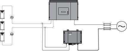
TheSMAPVOffsetBoxappliesavoltageagainstearthtoPVmodulesandinthiswaydissipatesany power-reducing charges in the PV modules.
The SMA PV Offset Box is intended exclusively for in-parallel operation on inverters with a maximum DC voltage of 400 V to 1,000 V.
Figure 1: Principle of a PV plant with SMA PV Offset Box and string inverter
The SMA PV Offset Box can be operated with both a string inverter and with an inverter with several inputs. In an inverter with several inputs, the negative PV inputs must be internally bridged for this purpose. This is the case with SMA multi-string inverters, providing that the DC switch-disconnector, Electronic Solar Switch (ESS) is plugged in.
Installation Manual |
PVO-BOX-IA-en-10 |
7 |
2 Safety |
|
|
|
|
|
|
|
|
|
|
|
|
|
|
|
|
|
|
SMA Solar Technology AG |
||||
|
|
|
|
|
|
|
|
|
|
|
|
|
|
|
|
|
|
|
|
|
|
|
|
|
|
|
|
|
|
|
|
|
|
|
|
|
|
|
|
|
|
|
|
|
|
|
|
|
|
|
|
|
|
|
|
|
|
|
|
|
|
|
|
|
|
|
|
|
|
|
|
|
|
|
|
|
|
|
|
|
|
|
|
|
|
|
|
|
|
|
|
|
|
|
|
|
|
|
|
|
|
|
|
|
|
|
|
|
|
|
|
|
|
|
|
|
|
|
|
|
|
|
|
|
|
|
|
|
|
|
|
|
|
|
|
|
|
|
|
|
|
|
|
|
|
|
|
|
|
|
|
|
|
|
|
|
|
|
|
|
|
|
|
|
|
|
|
|
|
|
|
|
|
|
|
|
|
|
|
|
|
|
|
|
|
|
|
|
|
|
|
|
|
|
|
|
|
|
|
|
|
|
|
|
|
|
|
|
|
|
|
|
|
|
|
|
|
|
|
|
|
|
|
|
|
|
|
|
|
|
|
|
|
|
|
|
|
|
|
|
|
|
|
|
|
|
|
|
|
|
|
|
|
|
|
|
|
|
|
|
|
|
|
|
|
|
|
|
|
|
|
|
|
|
|
|
|
|
|
|
|
|
|
|
|
|
|
|
|
|
|
|
|
|
|
|
|
|
|
|
|
|
|
|
|
|
|
|
|
|
|
|
|
|
|
|
|
|
|
|
|
|
|
|
|
|
|
|
|
|
|
|
|
|
|
|
|
|
|
|
|
|
|
|
|
|
|
|
|
|
|
|
|
|
|
|
|
|
|
|
|
|
|
|
|
|
|
|
|
|
|
|
|
|
|
|
|
|
|
|
|
|
|
|
|
|
|
|
|
|
|
|
|
|
|
|
|
|
|
|
|
|
|
|
|
|
|
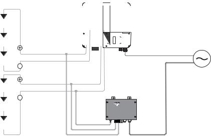
Figure 2: Principle of a PV plant with SMA PV Offset Box and multi-string inverter
No more than 1 SMA PV Offset Box must be connected per inverter. Exceptions to this rule are inverters with several inputs in which the negative DC inputs are not internally bridged.
1 SMA PV Offset Box per string can be connected to this type of inverter.
The SMA PV Offset Box can only be operated with PV plants having an insulation resistance (including insulation resistance of the inverter) of at least 200 kΩ.
The SMA PV Offset Box must only be operated with PV arrays (modules and cabling) of protection class II.
Before installing the SMA PV Offset Box, ensure that the permitted operating range of each component is maintained at all times.
You may only operate the SMA PV Offset Box once you have obtained the appropriate approval fromboththemanufacturerofthePVmodulesandthemanufactureroftheinverter.Noteanyrelevant restrictionsintheapprovals,e.g.,pertainingtothemaximumoutputvoltageoftheSMAPVOffsetBox.
Any applications other than those described here shall be considered contrary to the appropriate usage. Alternative uses or modifications to the SMA PV Offset Box will void the warranty claims and operation permit.
Appropriate usage also includes compliance with all the supplied documentation. Keep this manual in a convenient place for future reference.
8 |
PVO-BOX-IA-en-10 |
Installation Manual |
SMA Solar Technology AG |
2 Safety |
2.2 Qualifications of Skilled Persons
Theworkdescribedinthisdocumentmustbeperformedbyskilledpersonsonly.Skilledpersonsmust have the following qualifications:
•Knowledge of how an inverter works and is operated
•Traininginhowtodealwiththedangersandrisksinvolvedininstallingandoperatingelectrical devices and plants
•Training in the installation and commissioning of electrical devices and plants
•Knowledge of all applicable standards and directives
•Knowledge and observance of this document and all safety precautions
2.3 Safety precautions
Electric Shock
When the SMA PV Offset Box is in operation, voltage will be present in the PV array at night. Prior to any maintenance work on the PV plant:
•Disconnect the inverter from all voltage sources (see the inverter installation manual).
•Disconnect the SMA PV Offset Box from all voltage sources (see Section 9 "Disconnecting the SMA PV Offset Box from Voltage Sources", page 43).
IftheoutputvoltageoftheSMAPVOffsetBoxissettoohigh,theinsulationoftheconnectedinverters, PV modules or other DC-side components could be damaged. There is a risk of electric shock.
•Observe the maximum DC voltage of the PV modules, the inverter and any other DC-side components (see manufacturer specifications).
•Only connect approved PV modules and inverters.
•For SMA inverters, observe additional specifications on maximum DC voltage in the datasheet of the SMA PV Offset Box at www.SMA-Solar.com.
Electrostatic Discharge (ESD)
By touching electronic components you can cause damage to or destroy the SMA PV Offset Box through electrostatic discharge (ESD).
•Earth yourself on an earthed object before touching any component inside the SMA PV Offset Box Do not use the enclosure of the SMA PV Offset Box for this purpose, as it is not earthed.
Installation Manual |
PVO-BOX-IA-en-10 |
9 |
3 Scope of Delivery |
SMA Solar Technology AG |
3 Scope of Delivery
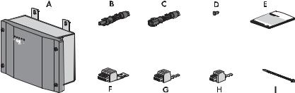
Check the scope of delivery for completeness and any visible external damage. Contact your specialist dealer if the delivery is incomplete or you find any damage.
Figure 3: Components included in the scope of delivery
Item |
Quantity |
Description |
A |
1 |
SMA PV Offset Box |
B |
2 |
Positive DC connector |
C |
1 |
Negative DC connector |
D |
1 |
Sealing plugs |
E |
1 |
Installation manual |
F |
1 |
4-pole plug with strain relief |
G |
1 |
3-pole plug with strain relief |
H |
1 |
2-pole plug with strain relief |
I |
6 |
Cable tie |
10 |
PVO-BOX-IA-en-10 |
Installation Manual |
SMA Solar Technology AG |
4 Product Description |
4 Product Description
4.1 SMA PV Offset Box
The SMA PV Offset Box dissipates power-reducing charges in PV modules.
Figure 4: Parts of the SMA PV Offset Box
Item |
Description |
Explanation |
A |
LEDs |
LEDs for operation and fault display |
B |
Type label |
‒ |
C |
Connection area |
CableglandsfortheACconnectionandDCconnector |
TheSMAPVOffsetBox is connectedinparallel withthe inverterandappliesavoltage againstearth to PV modules. It can apply a set voltage or automatically regulate its output voltage.
Depending onits configuration, the SMA PV Offset Box performs various functions. Overnight, it can dissipate PV modules charges which have accumulated during the day. In continuous operation, the SMA PV Offset Box regenerates PV modules whose efficiency was previously reduced.
The SMA PV Offset Box continually monitors the connection of the functional earthing (FE) and the insulation of the PV plant. Prior to starting operation, the SMA PV Offset Box checks whether the PV strings are reverse poled or interrupted. Faults are displayed via LEDs.
Installation Manual |
PVO-BOX-IA-en-10 |
11 |
4 Product Description |
SMA Solar Technology AG |
4.2 Fault Indication Relay
An external fault indicator can be connected via the fault indication relay in the SMA PV Offset Box. Depending on the type of electrical connection,the fault indicator is activatedeither inthe event of a disturbance or during fault-free operation of the SMA PV Offset Box.
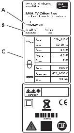
4.3 Type Label
The type label clearly identifies the SMA PV Offset Box. The type label is located on the right-hand side of the enclosure.
Figure 5: Layout of the type label
Item |
Description |
|
A |
Model |
Device type |
B |
Serial No. |
Serial number |
C |
Device-specific characteristics |
‒ |
The information on the type label will support you in the safe use of the SMA PV Offset Box and will be needed when you contact the SMA Service Line. The type label must be permanently affixed to the SMA PV Offset Box.
12 |
PVO-BOX-IA-en-10 |
Installation Manual |
SMA Solar Technology AG 4 Product Description
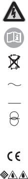
Symbols on the Type Label
Symbol |
Meaning |
Explanation |
||||||
|
|
|
|
|
|
|
Danger to life due to |
The SMA PV Offset Box operates at high voltages. All |
|
|
|
|
|
|
|
high voltages |
work on the SMA PV Offset Box must be performed by |
|
|
|
|
|
|
|
|
skilled workers only. |
|
|
|
|
|
|
|
Observe the |
Observe all the documentation supplied with the |
|
|
|
|
|
|
|
documentation. |
SMA PV Offset Box. |
|
|
|
|
|
|
|
|
|
|
|
|
|
|
|
|
Proper disposal |
Do not dispose of the SMA PV Offset Box with the |
|
|
|
|
|
|
|
||
|
|
|
|
|
|
|
||
|
|
|
|
|
|
|
||
|
|
|
|
|
|
|
|
household refuse. |
|
|
|
|
|
|
|
|
|
|
|
|
|
|
|
|
|
|
|
|
|
|
|
|
|
|
|
|
|
|
|
|
|
|
|
|
|
|
|
|
|
|
|
AC |
Alternating current |
|
|
|
|
|
|
|
|
|
|
|
|
|
|
|
|
DC |
Direct current |
|
|
|
|
|
|
|
||
|
|
|
|
|
|
|
|
|
|
|
|
|
|
|
|
With transformer |
The SMA PV Offset Box is equipped with a transformer. |
|
|
|
|
|
|
|
|
|
|
|
|
|
|
|
|
Protection class II |
The protection insulation of the SMA PV Offset Box is |
|
|
|
|
|
|
|
|
compliant with protection class II. |
|
|
|
|
|
|
|
|
|
|
|
|
|
|
|
|
|
|
|
|
|
|
|
|
|
CE marking |
The SMA PV Offset Box complies with the requirements |
|
|
|
|
|
|
|
|
of the applicable EC directives. |
|
|
|
|
|
|
|
Degree of protection: |
The SMA PV Offset Box is protected against dust |
|
|
|
|
|
|
|
IP65 |
intrusion and water jets from any angle. |
Installation Manual |
PVO-BOX-IA-en-10 |
13 |
4 Product Description |
SMA Solar Technology AG |
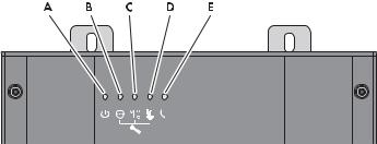
4.4 LEDs
Item |
Description |
Explanation |
A |
Green LED |
Indicates the operating state of the SMA PV Offset Box. |
B |
Red-yellow LED |
Indicates an FE connection fault or AC connection fault. |
C |
Red-yellow LED |
Indicates a DC connection fault. |
D |
Red-yellow LED |
Indicates an insulation fault. |
E |
Red-yellow LED |
Indicates a device fault. |
The LEDs for fault indication are 2-colour. They glow red if operation is currently interrupted. They glow yellow if a fault has previously occurred, but normal operation is currently possible.
14 |
PVO-BOX-IA-en-10 |
Installation Manual |

SMA Solar Technology AG |
5 Assembly |
5 Assembly
5.1 Selecting the Mounting Location
Requirements for the mounting location:
Danger to life due to fire or explosion
Despite careful construction, electrical devices can cause fires.
•Do not mount the SMA PV Offset Box on flammable construction materials.
•Do not mount the SMA PV Offset Box in the vicinity of highly flammable materials.
•Do not mount the SMA PV Offset Box in potentially explosive areas.
Theinstallationsitemustbefreelyandsafelyaccessibleatalltimeswithoutthenecessityforany auxiliary equipment (such as scaffolding or lifting platforms). Non-fulfillment of these criteria may restrict servicing.
The mounting surface must be even. The wall brackets of the SMA PV Offset Box must lie flush with the mounting surface.
The ambient temperature must be between − 25°C and +60°C.
The LED display of the SMA PV Offset Box must be readable.
The mounting location should be close to the inverter. If the device is mounted on the PV array, support by SMA Service will not be possible.
Installation Manual |
PVO-BOX-IA-en-10 |
15 |

5 Assembly |
SMA Solar Technology AG |
Dimensions for mounting:
Figure 6: Dimensions of the SMA PV Offset Box and the drill holes for mounting
Observe the permitted mounting positions:
•Mount the SMA PV Offset Box in a vertical position or tilted backwards by max. 45°. The connection area must point downwards.
Permitted and prohibited mounting positions
16 |
PVO-BOX-IA-en-10 |
Installation Manual |
SMA Solar Technology AG |
5 Assembly |
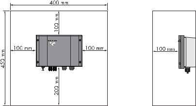
Observe recommended clearances:
•In order to have sufficient room for mounting, installation, and maintenance of the
SMAPVOffsetBox,observetherecommendedclearances.Inaddition,taketherecommended clearances of the inverter into account.
Figure 7: Recommended clearances
Installation Manual |
PVO-BOX-IA-en-10 |
17 |
Loading...