

ESHV-P-NR
DEENFR
ES
IT
GR
CZPTNL
ESHV-N-NR
Erdungsset
Anleitung zur Installation des positiven oder negativen Erdungssets
in einen Sunny Boy oder Sunny Mini Central.
Grounding Set
Guide on how to install the positive or negative grounding set in a
Sunny Boy or Sunny Mini Central.
Kit de mise à la terre
nstructions relatives à l’installation du kit de mise à la terre positif
ou négatif dans un Sunny Boy ou Sunny Mini Centra.
Kit de toma a tierra
Instrucciones de instalación del kit de toma a tierra positiva o
negativa en un inversor Sunny Boy o Sunny Mini Central.
Kit di messa a terra
Istruzioni per l‘installazione del kit di messa a terra positiva e
negativa in un Sunny Boy o in un Sunny Mini Central.
σετ γείωσης
Οδηγίες για την τοποθέτηση του θετικού ή του αρνητικού σετ
γείωσης σε έναν μετατροπέα Sunny Boy ή σε έναν Sunny Mini
Central.
Zemnicí sada
Návod k instalaci pozitivní a negativní zemnicí sady do střídače
Sunny Boy nebo Sunny Mini Central.
Kit de ligação à terra
Manual de instalação do kit de ligação à terra positiva ou
negativa num Sunny Boy ou Sunny Mini Central.
Aardingsset
Handleiding voor de installatie van de positieve of negatieve
aardingsset in een Sunny Boy of Sunny Mini Central.
Seite 3
Page 13
Page 23
Página 33
Pagina 43
Σελίδα 53
Strana 63
Página 73
Pagina 83
ESHV-IXX103013 | TBX-ESHV | Version 1.3


SMA Solar Technology AG Hinweise zu dieser Anleitung
1 Hinweise zu dieser Anleitung
1.1 Zielgruppe
Ausschließlich ausgebildete Elektrofachkräfte dürfen das Erdungsset installieren und in Betrieb
nehmen.
1.2 Verwendete Symbole
In diesem Dokument werden die folgenden vier Arten von Sicherheitshinweisen sowie allgemeine
Hinweise verwendet:
GEFAHR!
„GEFAHR“ kennzeichnet einen Sicherheitshinweis, dessen Nichtbeachtung unmittelbar
zum Tod oder zu schwerer Körperverletzung führt!
ACHTUNG!
„ACHTUNG“ kennzeichnet einen Sicherheitshinweis, dessen Nichtbeachtung zu
Sachschäden führen kann!
Hinweis
Ein Hinweis kennzeichnet Informationen, die für den optimalen Betrieb des Produktes
wichtig sind.
2 Sicherheit
2.1 Bestimmungsgemäße Verwendung
Wenn Sie spezielle Zelltechnologien in Ihrem PV-Generator einsetzen (z. B. Dünnschicht- oder
rü cks eit enk ont akt ier te PV -Mo dul e), kan n es n otw end ig s ein , de n PV-Generator positiv oder negativ zu
erden. Hierfür hat SMA Solar Technology zwei Erdungssets entwickelt, mit denen die vom
Modulhersteller empfohlene positive oder negative Erdung des PV-Generators bereits im
Wechselrichter vorgenommen werden kann. Durch diese geräteinterne Erdung wird ein langfristig
sicherer Betrieb bei optimalen EMV-Eigenschaften und eine Minimierung der Installationskosten
erreicht.
Das Erdungsset beinhaltet eine 1 A- Sicherung als Schutz gegen Brandgefahr und eine Schaltung, die
die Isolationsüberwachung des Wechselrichters auf das Erdungsset abstimmt. Das Erdungsset stellt
über die Sicherung eine direkte Verbindung zwischen dem zu erdenden Pol (Plus oder Minus) der PVModule und dem PE-Anschluss des Wechselrichters her. Diese Schaltung wurde für Deutschland
konzipiert und ist jedoch für viele weitere Länder geeignet. Prüfen Sie vor der Installation, ob die
Erdung eines Pols im Installationsland erlaubt ist.
Installationsanleitung ESHV-IXX103013 3
Sicherheit SMA Solar Technology AG
Das positive Erdungsset (ESHV-P-NR) wird zum Beispiel bei bestimmten Modulen mit rückseitig
kontaktierten Zellen verwendet. Das negative Erdungsset (ESHV-N-NR) wird zum Beispiel bei
bestimmten Dünnschichtmodulen verwendet. Informationen über Art und Notwendigkeit der
Modulerdung in Ihrer PV-Anlage erhalten Sie von Ihrem Modulhersteller.
Sie dürfen das Erdungsset nur bei folgenden SMA Wechselrichtern mit Transformator einsetzen:
• Sunny Boy 1100 • Sunny Boy 3000 • Sunny Mini Central 4600A
• Sunny Boy 1200 • Sunny Boy 3300 • Sunny Mini Central 5000A
• Sunny Boy 1700 • Sunny Boy 3800 • Sunny Mini Central 6000A
• Sunny Boy 2500 • Sunny Mini Central 7000HV
Der Wechselrichter darf dabei nur an PV-Generatoren (Module und Verkabelung) betrieben werden,
die schutzisoliert aufgebaut sind (Schutzklasse II).
2.2 Sicherheitshinweise
GEFAHR!
Lebensgefahr durch hohe Spannungen im Wechselrichter!
• Alle Arbeiten am Wechselrichter und der Einbau des Erdungssets dürfen
ausschließlich durch eine ausgebildete Elektrofachkraft erfolgen.
• Öffnen und schließen Sie den Wechselrichter ausschließlich wie in dessen
Installationsanleitung beschrieben.
ACHTUNG!
Beschädigung des Erdungssets oder des Wechselrichters durch fehlerhaften
Anschluss!
Ein fehlerhafter Anschluss des Erdungssets kann zu Kurzschlüssen und irreparablen
Schäden des Erdungssets und des Wechselrichters führen. Jegliche
Gewährleistungsansprüche erlöschen.
• Erdungsset anschließen, wie in dieser Installationsanleitung beschrieben
ACHTUNG!
Beschädigung des Wechselrichters durch elektrostatische Entladung!
Bauteile im Inneren des Wechselrichters können durch statische Entladung irreparabel
beschädigt werden.
• Erden Sie sich vor Berühren eines Bauteils.
4 ESHV-IXX103013 Installationsanleitung
SMA Solar Technology AG Lieferumfang
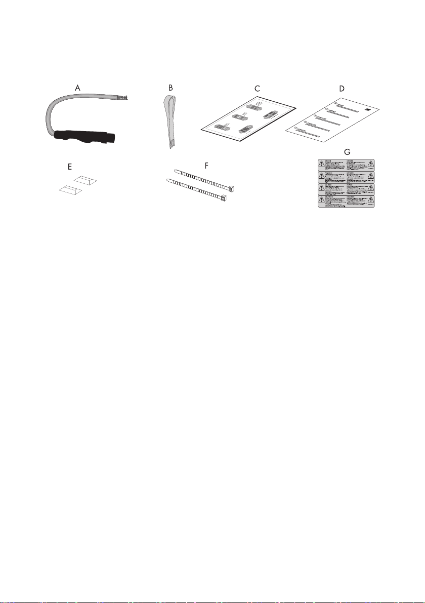
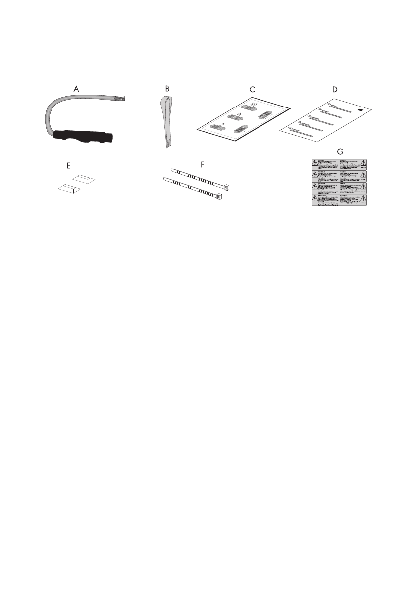
3 Lieferumfang
A 1 Erdungsset
B 1 Betätigungswerkzeug
C 1 Folie mit Aufklebern für die Varistorklemmenblöcke
D 1 Installationsanleitung
E 2 Klebesockel
F 2 Kabelbinder
G 4 Warnaufkleber für den Wechselrichter (sprachabhängig)
Installationsanleitung ESHV-IXX103013 5
Installation SMA Solar Technology AG
1
2
3
4
5
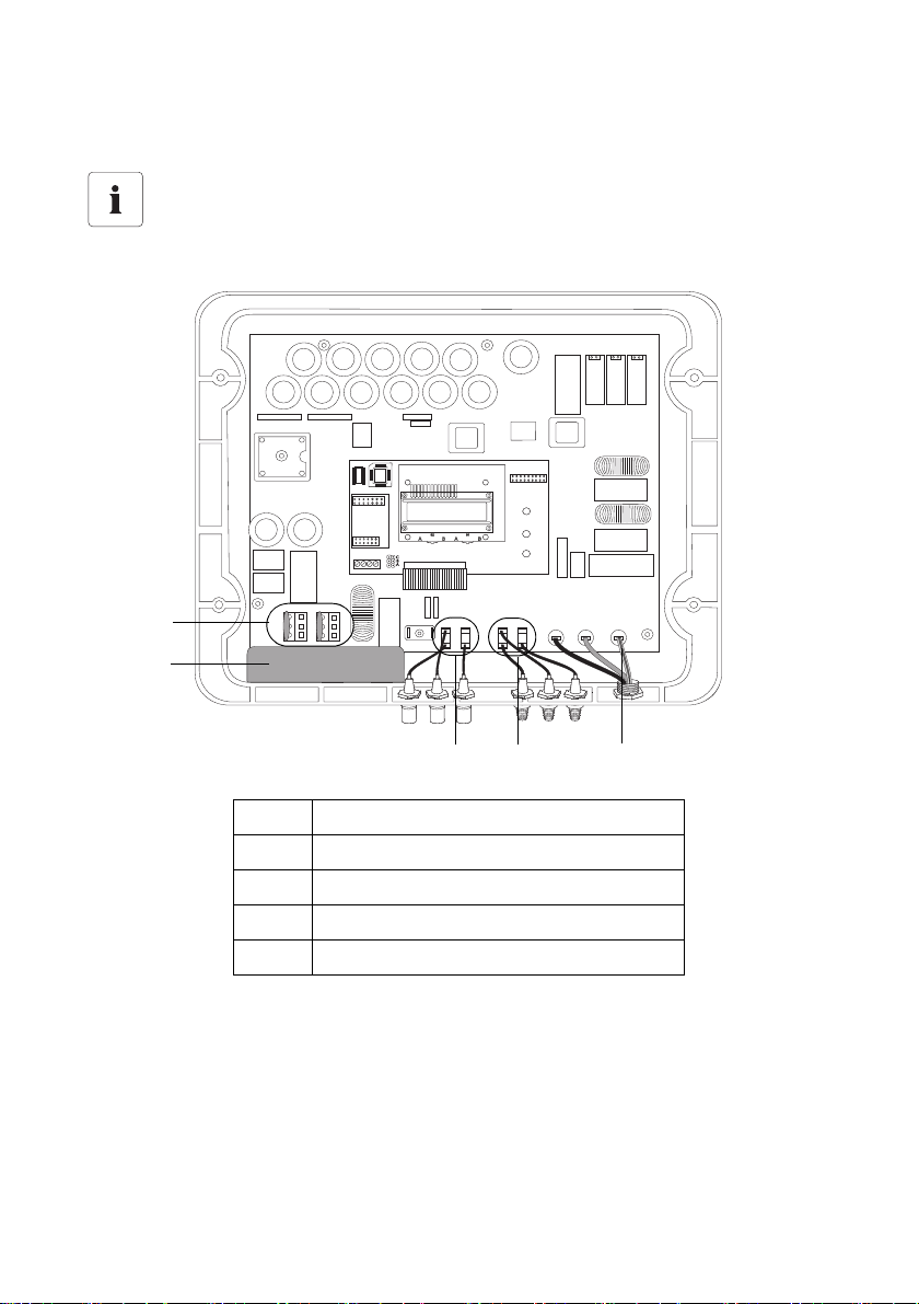
4 Installation
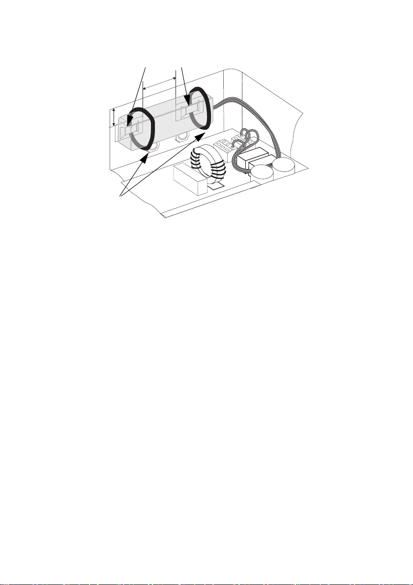
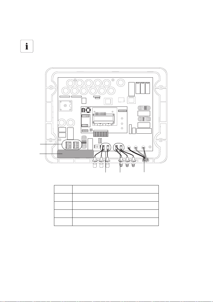
Exemplarische Zeichnungen
Die Zeichnungen in diesem Kapitel sind exemplarisch für den Sunny Boy 3800. Die
Position der Varistoren und des Erdungssets für die anderen Wechselrichtertypen können
Sie den Zeichnungen ab Seite 93 entnehmen.
1 Position der Varistoren
2 Position des Erdungssets
3DC +
4DC −
5 PE-Anschluss der AC-Leitung
6 ESHV-IXX103013 Installationsanleitung
SMA Solar Technology AG Installation
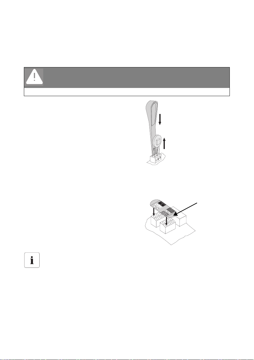
Das Einführen des
Betätigungswerkzeugs löst
die Klemme.
Varistor entnehmen.
Aufkleber
anbringen und
Laschen
umklappen.
1. Prüfen, um welches Erdungsset es sich handelt:
– Erdungsset positiv: rote Ummantelung, drei Anschlüsse in den Farben rot, weiß, blau
– Erdungsset negativ: schwarze Ummantelung, vier Anschlüsse in den Farben rot, weiß, blau,
schwarz
GEFAHR!
Lebensgefahr durch hohe Spannungen im Wechselrichter!
• Wechselrichter öffnen, wie in dessen Installationsanleitung beschrieben.
2. Beide Varistoren entfernen.
Verwenden Sie dazu das mitgelieferte
Betätigungswerkzeug. Sie können jedoch die
Klemmenkontakte auch einzeln mit einem
passenden Schraubendreher bedienen.
3. Mitgelieferten Aufkleber des entsprechenden
Wechselrichter-Typs langsam von der Folie ziehen.
Prüfen Sie dabei, ob die Folie aus den gestanzten
Löchern enfernt wurde.
4. Aufkleber auf den Varistorklemmenblock kleben.
Die eckigen Löcher des Aufkleber müssen dabei
über den eckigen Öffnungen des
Varistorklemmenblocks liegen.
5. Überstehende Laschen herunterklappen und an
den Seiten festdrücken.
Positionierung des Aufklebers
Nur durch die richtige Positionierung des entsprechenden Varistoraufklebers ist der
verpolsichere Anschluss und die sichere Funktion des Erdungssets gewährleistet.
Installationsanleitung ESHV-IXX103013 7
Installation SMA Solar Technology AG
2
0
m
m
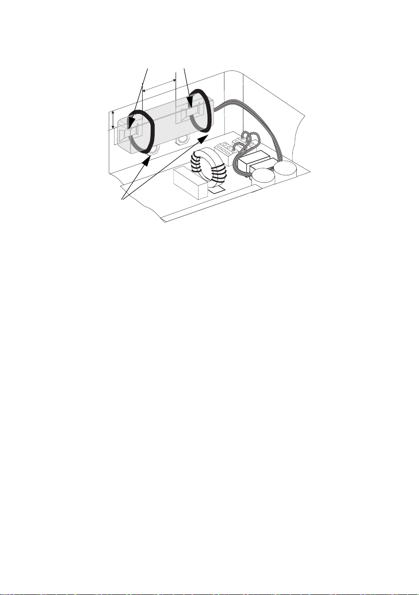
Position der Klebesockel
Kabelbinder
20 mm
6. Fläche, an der das Erdungsset befestigt wird, mit einem fettlösenden nicht ätzenden
Reinigungsmittel reinigen. Dabei darf keine Feuchtigkeit auf die Elektronik des Wechselrichters
gelangen.
7. Die beiden Klebesockel in einem Abstand von ca. 2 cm zueinander anbringen und ca. 5
Sekunden fest anpressen.
8. Kabelbinder durch die Laschen der Klebesockel hindurchführen.
9. Erdungsset mit Hilfe der Kabelbinder befestigen und Kabelbinder anschließend kürzen.
10. Anschlussleitungen des Erdungssets zum Varistorklemmenblock führen.
11. Anschlussleitungen mit Hilfe des Betätigungswerkzeugs in den runden Varistorklemmen mit der
entsprechenden farbigen Aufklebermarkierung befestigen (rotes Kabel in rote Markierung
usw.).
12. Aderendhülsen dabei bis zum Anschlag in die Klemmen drücken.
13. Anschluss auf Verpolsicherheit prüfen:
Optische Kontrolle:
– Ist der Aufkleber richtig positioniert?
– Ist er dem richtigen Wechselrichtertyp zugeordnet?
– Entspricht die Farbe der Anschlusskabel der der Klemmen?
8 ESHV-IXX103013 Installationsanleitung
SMA Solar Technology AG Installation
Messung des Widerstands:
– Prüfen, ob der Leitungsschutzschalter ausgeschaltet ist und alle DC-Steckverbinder vom
Wechselrichter abgezogen sind.
– Electronic Solar Switch in dessen Buchse am Wechselrichter stecken.
Die Messung ist sonst nicht möglich.
– Widerstand zwischen DC und dem PE-Anschluss der AC-Leitung messen.
Die Position der Messpunkte ist in den Übersichtsbildern in Kapitel „Sunny Boy / Sunny Mini
Central“ (93) eingezeichnet.
– positives Erdungsset:
Der Widerstand zwischen DC + und dem PE-Anschluss der AC-Leitung darf nicht größer
als 0,5 Ohm sein.
– negatives Erdungsset
Der Widerstand zwischen DC - und dem PE-Anschluss der AC-Leitung darf nicht größer
als 0,5 Ohm sein.
14. Electronic Solar Switch abziehen und Wechselrichter schließen, wie in dessen
Installationsanleitung beschrieben.
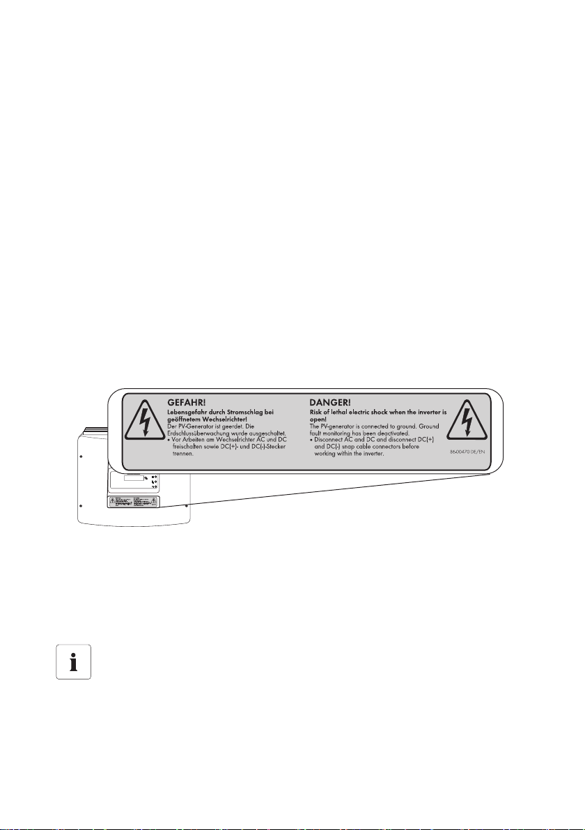
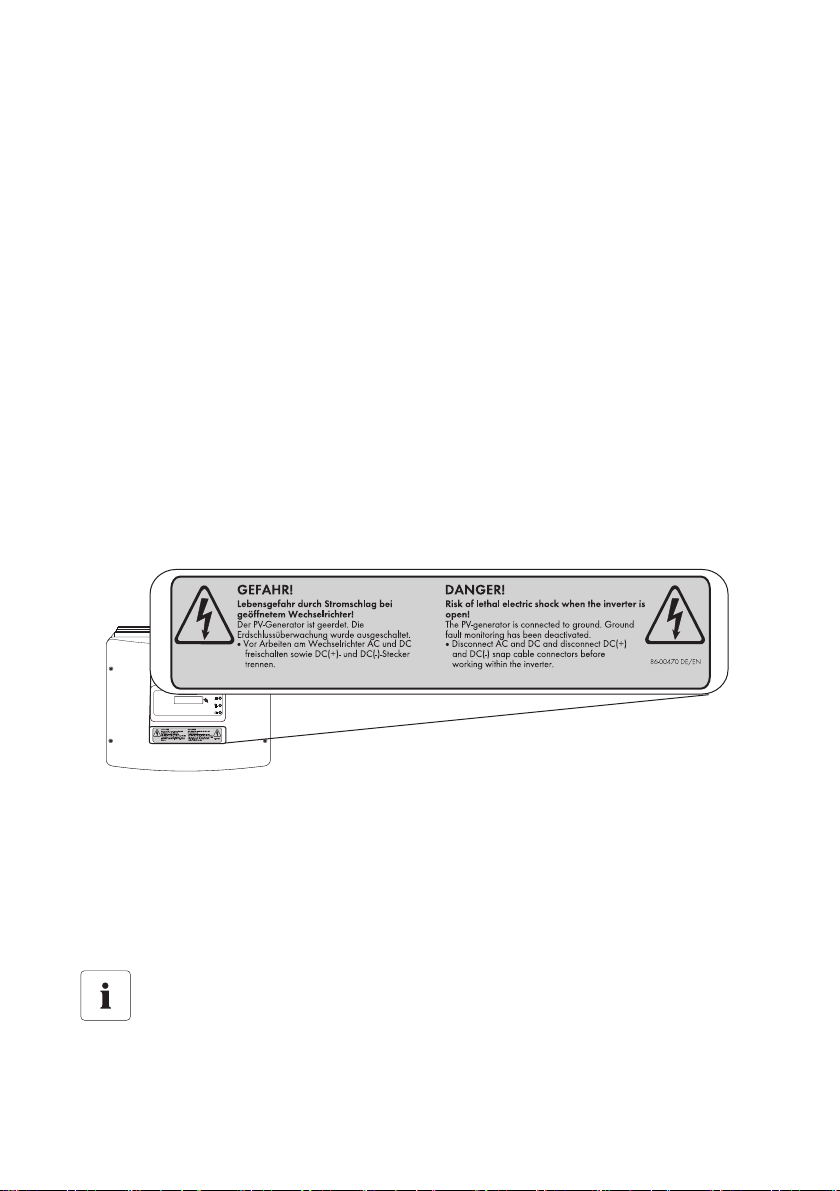
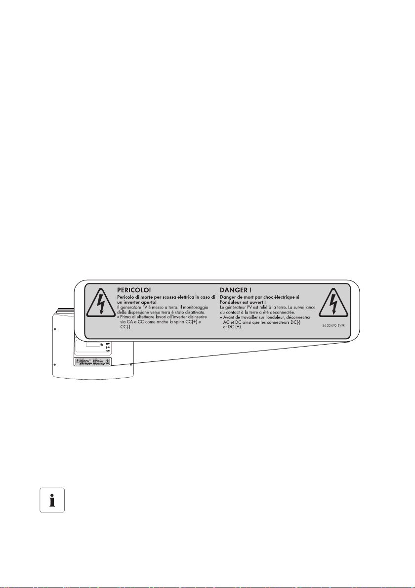
15. Einen der vier mitgelieferten Warnaufkleber mit der entsprechenden Sprache auswählen und
auf dem Wechselrichter anbringen.
16. Leitfähige Teile der Unterkonstruktion des PV-Generators mit der Erdungsanlage verbinden.
Einige Modulhersteller fordern die Erdung eines Generatorpols, um Potenzialdifferenzen
zwischen Erdpotenzial des Erdungssets und der Umgebung des PV-Generators zu vermeiden.
Durch die Erdung der Unterkonstruktion des PV-Generators werden diese Potenzialdifferenzen
vermieden. Zusätzlich bietet dieser Potenzialausgleich den bestmöglichen Schutz durch die im
Erdungsset integrierte Sicherung.
Anzeige eines Erdschlusses
Wenn das Erdungsset eingebaut ist und die rote LED des Wechselrichters leuchtet, liegt ein
ungewollt er Erschluss im PV-Generator vo r. Beheben Sie di e Ursache des Erdschlusses und
tauschen Sie das Erdungsset aus.
Installationsanleitung ESHV-IXX103013 9

Kontakt SMA Solar Technology AG
5 Kontakt
Bei Fragen zum Erdungsset oder bei technischen Problemen wenden Sie sich an unsere Serviceline.
Wir benötigen die folgenden Daten, um Ihnen gezielt helfen zu können:
• Wechselrichtertyp
• Seriennummer des Wechselrichters
• Angeschlossene Module und Anzahl der Module
• Art des eingebauten Erdungssets (positiv oder negativ)
• Blinkcode oder Displayanzeige des Wechselrichters
• Kommunikationsart
SMA Solar Technology AG
Sonnenallee 1
34266 Niestetal
www.SMA.de
SMA Serviceline
Wechselrichter: +49 561 9522 1499
Kommunikation: +49 561 9522 2499
SMS mit „RÜCKRUF“ an: +49 176 888 222 44
Fax: +49 561 9522 4699
E-Mail: Serviceline@SMA.de
10 ESHV-IXX103013 Installationsanleitung

SMA Solar Technology AG Rechtliche Bestimmungen
Die in diesen Unterlagen enthaltenen Informationen sind Eigentum der SMA Solar Technology AG. Die Veröffentlichung, ganz
ode r in T eilen , beda rf de r schr iftlich en Zustimm ung d er SMA Solar Technology AG. Eine innerbetriebliche Vervielfältigung, die zur
Evaluierung des Produktes oder zum sachgemäßen Einsatz bestimmt ist, ist erlaubt und nicht genehmigungspflichtig.
Haftungsausschluss
Es gelten als Grundsatz die Allgemeinen Lieferbedingungen der SMA Solar Technology AG.
Der Inhalt dieser Unterlagen wird fortlaufend überprüft und gegebenenfalls angepasst. Trotzdem können Abweichungen nicht
ausgeschlossen werden. Es wird keine Gewähr für Vollständigkeit gegeben. Die jeweils aktuelle Version ist im Internet unter
www.SMA.de abrufbar oder über die üblichen Vertriebswege zu beziehen.
Gewährleistungs- und Haftungsansprüche bei Schäden jeglicher Art sind ausgeschlossen, wenn sie auf eine oder mehrere der
folgenden Ursachen zurückzuführen sind:
• Transportschäden
• Unsachgemäße oder nicht bestimmungsgemäße Verwendung des Produkts
• Betreiben des Produkts in einer nicht vorgesehenen Umgebung
• Betreiben des Produkts unter Nichtberücksichtigung der am Einsatzort relevanten gesetzlichen Sicherheitsvorschriften
• Nichtbeachten der Warn- und Sicherheitshinweise in allen für das Produkt relevanten Unterlagen
• Betreiben des Produkts unter fehlerhaften Sicherheits- und Schutzbedingungen
• Eigenmächtiges Verändern oder Reparieren des Produkts oder der mitgelieferten Software
• Fehlverhalten des Produkts durch Einwirkung angeschlossener oder benachbarter Geräte außerhalb der gesetzlich zulässigen
Grenzwerte
• Katastrophenfälle und höhere Gewalt
Die Nutzung der mitgelieferten von der SMA Solar Technology AG hergestellten Software unterliegt zusätzlich den folgenden
Bedingungen:
• Die SMA Solar Technology AG lehnt jegliche Haftung für direkte oder indirekte Folgeschäden, die sich aus der Verwendung
der von SMA Solar Technology AG erstellten Software ergeben, ab. Dies gilt auch für die Leistung beziehungsweise NichtLeistung von Support-Tätigkeiten.
• Mitgelieferte Software, die nicht von der SMA Solar Technology AG erstellt wurde, unterliegt den jeweiligen Lizenz- und
Haftungsvereinbarungen des Herstellers.
SMA Werksgarantie
Die aktuellen Garantiebedingungen liegen Ihrem Gerät bei. Bei Bedarf können Sie diese auch im Internet unter www.SMA.de
herunterladen oder über die üblichen Vertriebswege in Papierform beziehen.
Warenzeichen
Alle Warenzeichen werden anerkannt, auch wenn diese nicht gesondert gekennzeichnet sind. Fehlende Kennzeichnung bedeutet
nicht, eine Ware oder ein Zeichen seien frei.
Die Bluetooth
Marken durch die SMA Solar Technology AG erfolgt unter Lizenz.
SMA Solar Technology AG
Sonnenallee 1
34266 Niestetal
Deutschland
Tel. +49 561 9522-0
Fax +49 561 9522-100
www.SMA.de
E-Mail: info@SMA.de
© 2004 bis 2010 SMA Solar Technology AG. Alle Rechte vorbehalten.
®
Wortmarke und Logos sind eingetragene Warenzeichen der Bluetooth SIG, Inc. und jegliche Verwendung dieser
Installationsanleitung ESHV-IXX103013 11

SMA Solar Technology AG Notes on this Guide
1 Notes on this Guide
1.1 Target Group
Only qualified electricians may install and commission the grounding set.
1.2 Symbols Used
The following four types of safety instructions and general information appear in this document as
described below:
DANGER!
DANGER indicates a hazardous situation which, if not avoided, will result in death or
serious injury.
NOTICE!
NOTICE indicates a situation that can result in property damage if not avoided.
Information
Information provides tips that are valuable for the optimal installation and operation of
your product.
2 Security
2.1 Appropriate Usage
If you use special cell technologies in your PV generator (e.g. thin-film PV modules and back-contact
PV modules), it may be necessary to ground the PV generator, either positively or negatively. With this
in mind SMA Solar Tec hnolog y has developed two grounding sets with which the positive or negative
grounding of the PV generator, as recommended by the module manufacturer, can be performed
already within the inverter. This device-internal grounding provides safe long-term operation and
optimum EMC properties while minimizing the installation costs.
The grounding set includes a 1 A fuse as protection against the danger of fire and a circuit adjusting
the inverter's isolation monitoring to the grounding set. The grounding set directly connects the pole
to be grounded (plus or minus) of the PV modules and the inverter's PE connection via the fuse. This
circuit has been designed for Germany and is suitable for many other countries as well. Before
installation, check if the installation country allows to connect a pole to ground.
The positive grounding set (ESHV-P-NR) is used, for example, for certain modules with back-contact
cells. The negative grounding set (ESHV-N-NR) is used, for example, for thin-film modules. Your
module manufacturer can provide you with information on the necessity and type of grounding of
your PV system.
Installation Guide ESHV-IXX103013 13
Security SMA Solar Technology AG
Only use the grounding set with the following SMA inverters with transformer:
• Sunny Boy 1100 • Sunny Boy 3000 • Sunny Mini Central 4600A
• Sunny Boy 1200 • Sunny Boy 3300 • Sunny Mini Central 5000A
• Sunny Boy 1700 • Sunny Boy 3800 • Sunny Mini Central 6000A
• Sunny Boy 2500 • Sunny Mini Central 7000HV
The inverter may only be operated with PV generators (modules and cabling) constructed with
protective insulation (protection class II).
2.2 Safety Precautions
DANGER!
Danger to life due to high voltages in the inverter!
• All work on the inverter and the installation of the grounding set must be carried out
by a qualified electrician.
• Open and close the inverter only as described in its installation guide.
NOTICE!
Faulty connection can damage the grounding set or inverter!
Faulty connection of the grounding set can lead to short circuits and cause irreparable
damage to the grounding set and the inverter. Any warranty claims thus become void.
• Connect the grounding set as described in this installation guide.
NOTICE!
Electrostatic discharges can damage the inverter!
Internal components of the inverter can be irreparably damaged by static discharge.
• Ground yourself before you touch a component.
14 ESHV-IXX103013 Installation Guide

SMA Solar Technology AG Packing List
3 Packing List
A 1 grounding set
B 1 extractor tool
C 1 label sheet for the varistor terminal block
D 1 Installation Guide
E 2 adhesive mounting bases
F 2 cable ties
G 4 warning labels for the inverter (in the required language)
Installation Guide ESHV-IXX103013 15

Installation SMA Solar Technology AG
1
2
3
4
5
4 Installation
Example Drawings
Th e dr awi ngs in t his sec tio n ar e ba sed on t he e xam ple of t he S unny Boy 3800. Please refer
to the drawings starting on page 93 for the position of varistors and grounding set for the
other inverter types.
1 Position of varistors
2 Position of grounding set
3DC +
4DC −
5PE connector for AC cable
16 ESHV-IXX103013 Installation Guide

SMA Solar Technology AG Installation
Insert the extractor tool to
open the terminal clamp.
Remove the varistor.
Attach the
label and fold
down the
flaps.
1. Check which grounding set is being installed:
– Positive grounding set: red cable covering, three connections in the colors red, white, blue
– Negative grounding set: black cable covering, four connections in the colors red, white,
blue, black
DANGER!
Danger to life due to high voltages in the inverter!
• Open the inverter as described in its installation guide.
2. Remove both varistors.
For this purpose, use the extractor tool provided. As
an alternative, however, the terminal contacts can
be operated individually using a suitable
screwdriver.
3. Peel the delivered labels for the respective inverter type slowly from the label sheet. Check that
the label material is removed from the perforated holes.
4. Attach the label to the varistor terminal block. The
rectangular holes in the label must be placed over
the rectangular openings in the varistor terminal
block.
5. Fold down the overlapping flaps and press firmly at
the sides.
Positioning of the Label
A reverse polarity protected connection of the grounding set and secure functioning can
only be guaranteed if the relevant varistor label is positioned correctly.
Installation Guide ESHV-IXX103013 17
Installation SMA Solar Technology AG
2
0
m
m
Position of the adhesive mounting base
Cable ties
20 mm
6. Clean the surface to which the grounding set will be affixed with a degreasing, non-corrosive
cleaning agent. Take care to ensure that no moisture reaches the inverter's electronics.
7. Attach the two adhesive mounting bases about 2 cm apart from each other and press firmly for
5 seconds.
8. Feed the cable ties through the slots in the mounting base.
9. Fasten the grounding set with the aid of cable ties, then shorten the cable ties.
10. Feed the connection cables of the grounding set to the varistor terminal block.
11. Use the extractor tool to fasten the connection cables in the round varistor terminals with the
corresponding colored labeling (red cable to the terminal marked red, etc.).
12. Push the cable end sleeves all the way into the terminals.
13. Check the connection for reverse polarity protection:
Visual Inspection:
– Is the label properly positioned?
– Does it correspond to the right inverter type?
– Do the connection cable colors correspond to the terminal colors?
18 ESHV-IXX103013 Installation Guide
SMA Solar Technology AG Installation
Resistance Measurement:
– Check if the line circuit breaker is switched off and that all DC plug connectors have been
disconnected from the inverter.
– Insert the Electronic Solar Switch in its socket on the inverter.
Otherwise the measurement cannot be made.
– Measure the resistance between DC and the AC cables PE connector.
The position of the measuring points is illustrated in the overview diagrams in section
„Sunny Boy / Sunny Mini Central“ (93).
– Positive grounding set:
The resistance between DC + and the AC cables PE connector must not exceed
0.5Ohms.
– Negative grounding set:
The resistance between DC - and the AC cables PE connector must not exceed
0.5Ohms.
14. Disconnect the Electronic Solar Switch and close the inverter as described in its installation
guide.
15. Choose one of the four warning labels provided, with the appropriate language, and attach it
to the inverter.
16. Connect the conductive part of the under-construction of the PV generator with the grounding
system.
Certain module manufacturers demand the grounding of a generator pole in order to avoid
potential differences between the ground potential of the grounding set and the surrounding of
the PV generator. By grounding the under-construction of the PV generator these potential
differences will be avoided. Additionally this potential equalization provides the best possible
protection via the fuse integrated in the grounding set.
Display of a Ground Fault
If the grounding set is installed, and the inverters red LED shines, an undesired grounding
fault is present in the PV generator. Remove the cause of the grounding fault, and replace
the grounding set.
Installation Guide ESHV-IXX103013 19

Contact SMA Solar Technology AG
5 Contact
If you have any questions or technical problems concerning the grounding set, contact our SMA
Serviceline. We require the following information in order to provide you with the necessary
assistance:
•inverter type
• inverter's serial number
• type and number of modules connected
• type of installed grounding set (positive or negative)
• inverter's blink code or display
• communication method
SMA Solar Technology AG
Sonnenallee 1
34266 Niestetal, Germany
www.SMA.de
SMA Serviceline
Inverters: +49 561 9522 1499
Communication: +49 561 9522 2499
Fax: +49 561 9522 4699
E-Mail: Serviceline@SMA.de
20 ESHV-IXX103013 Installation Guide

SMA Solar Technology AG Legal Restrictions
The information contained in this document is the property of SMA Solar Technology AG. Publishing its content, either partially or
in full, requires the written permission of SMA Solar Technology AG. Any internal company copying of the document for the
purposes of evaluating the product or its correct implementation is allowed and does not require permission.
Exclusion of liability
The general terms and conditions of delivery of SMA Solar Technology AG shall apply.
The content of these documents is continually checked and amended, where necessary. However, discrepancies cannot be
excluded. No guarantee is made for the com pleteness of these documents. The latest version is available online at www.SMA.de
or from the usual sales channels.
Guarantee or liability claims for damages of any kind are excluded if they are caused by one or more of the following:
• Damages during transportation
• Improper or inappropriate use of the product
• Operating the product in an unintended environment
• Operating the product whilst ignoring relevant, statutory safety regulations in the deployment location
• Ignoring safety warnings and instructions contained in all documents relevant to the product
• Operating the product under incorrect safety or protection conditions
• Altering the product or supplied software without authority
• The product malfunctions due to operating attached or neighboring devices beyond statutory limit values
• In case of unforeseen calamity or force majeure
The use of supplied software produced by SMA Solar Technology AG is subject to the following conditions:
• SMA Solar Technology AG rejects any liability for direct or indirect damages arising from the use of software developed by
SMA Solar Technology AG. This also applies to the provision or non-provision of support activities.
• Supplied software not developed by SMA Solar Technology AG is subject to the respective licensing and liability agreements
of the manufacturer.
SMA Factory Warranty
The current guarantee conditions come enclosed with your device. These are also available online at www.SMA.de and can be
downloaded or are available on paper from the usual sales channels if required.
Trademarks
All trademarks are recognized even if these are not marked separately. Missing designations do not mean that a product or brand
is not a registered trademark.
The Bluetooth
Solar Technology AG is under license.
SMA Solar Technology AG
Sonnenallee 1
34266 Niestetal
Germany
Tel. +49 561 9522-0
Fax +49 561 9522-100
www.SMA.de
E-Mail: info@SMA.de
© 2004 to 2010 SMA Solar Technology AG. All rights reserved
®
wor d mark an d logos are registere d trademarks owned by Bl uetooth SI G, Inc. a nd any use of s uch marks b y SMA
Installation Guide ESHV-IXX103013 21

SMA Solar Technology AG Remarques concernant ce guide d‘installation et d'utilisation
1 Remarques concernant ce guide d‘installation et d'utilisation
1.1 Groupe cible
L‘installation et la mise en service du kit de mise à la terre doivent être exclusivement effectuées par
des électriciens qualifiés.
1.2 Symboles utilisés
Dans ce document sont utilisés les types de consignes de sécurité suivants ainsi que des remarques
générales:
DANGER !
« DANGER » indique une consigne de sécurité dont le non-respect entraîne inévitablement
des blessures corporelles graves voire la mort !
PRUDENCE !
« PRUDENCE » indique une consigne de sécurité dont le non-respect peut entraîner des
dommages matériels !
Remarque
Une remarque indique une information essentielle pour le fonctionnement optimal du
produit !
2 Sécurité
2.1 Utilisation conforme
Si vous utilisez des technologies cellulaires spéciales dans votre générateur PV (par exemple
panneaux PV à couche mince ou basés sur une conception de contacts en face arrière entrecroisés),
il peut être nécessaire de procéder à une mise à la terre positive ou négative du générateur PV. Pour
cela, SMA Solar Technology a conçu deux kits de mise à la terre qui permettent la mise à la terre
positive ou négative du générateur PV dès l’onduleur, comme cela est conseillé par le fabricant des
panneaux. Cette mise à la terre interne à l‘appareil permet une exploitation fiable à long terme avec
des propriétés CEM optimales et une réduction des coûts d’installation.
Le kit de raccordement à la terre comporte un fusible de 1 A comme protection contre le risque
d'incendie et un fusible accordant la surveillance d'isolement de l'onduleur avec le kit de
raccordement à la terre. Par le fusible, le kit de raccordement à la terre établit une connexion directe
entre le fil à mettre à la terre (positif ou négatif) des panneaux photovoltaïques et le raccordement PE
de l'onduleur. Ce circuit est conçu pour l'Allemagne, mais est également approprié pour beaucoup
d' aut res pay s. A van t l' ins tal lation, vér ifi ez s i le rac cor dem ent à la ter re d 'un fil est aut ori sé d ans le pa ys
d'installation.
Instructions d’installation ESHV-IXX103013 23

Sécurité SMA Solar Technology AG
Le kit de mise à la te rre pos itif (ESHV-P-NR ) est par ex emple u tilisé sur certains panneaux avec cellules
à contacts en face arrière. Le kit de mise à la terre négatif (ESHV-N-NR) est par exemple utilisé avec
certains panneaux à couche mince. C’est votre fabricant de panneaux solaires qui vous fournira les
informations sur la nécessité et le type de la mise à la terre de votre installation PV.
Le kit de mise à la terre peut uniquement être utilisé avec les onduleurs SMA suivants, en présence
d’un transformateur :
• Sunny Boy 1100 • Sunny Boy 3000 • Sunny Mini Central 4600A
• Sunny Boy 1200 • Sunny Boy 3300 • Sunny Mini Central 5000A
• Sunny Boy 1700 • Sunny Boy 3800 • Sunny Mini Central 6000A
• Sunny Boy 2500 • Sunny Mini Central 7000HV
L’onduleur peut uniquement être exploité avec des générateurs PV (panneaux et câblage) protégés
par isolation (classe de protection II).
2.2 Consignes de sécurité
DANGER !
Haute tension dans l'onduleur. Danger de'mort!
• Tous les travaux sur l‘onduleur et l'installation du kit de mise à la terre ne doivent être
effectués que par un électricien professionnel habilité.
• Ouvrez et fermez l‘onduleur toujours en respectant les instructions d'installation.
PRUDENCE !
Un raccordement incorrect peut entraîner l’endommagement du kit de mise à la
terre ou de l’onduleur !
Un raccordement incorrect du kit de mise à la terre peut entraîner des courts-circuits et des
dommages irréparables du kit de mise à la terre et de l‘onduleur. Toutes les conditions de
garantie expirent.
• Raccordez le kit de mise à la terre comme cela est décrit dans ce guide d’installation.
PRUDENCE !
L‘onduleur peut être endommagé par des décharges électrostatiques!
Les composants à l‘intérieur de l'onduleur peuvent être endommagés de manière
irréversible par des décharges électrostatiques.
• Reliez-vous à la terre avant de manipuler un des composants.
24 ESHV-IXX103013 Instructions d’installation

SMA Solar Technology AG Contenu de la livraison
3 Contenu de la livraison
A 1 Kit de mise à la terre
B 1 Outil d‘extraction
C 1 Film avec autocollants pour les répartiteurs du varistor
D 1 Instructions d‘installation
E 2 Socles adhésifs
F 2 colliers de serrage
G 4 Autocollants d’avertissement pour l’onduleur (en fonction de la langue)
Instructions d’installation ESHV-IXX103013 25
Installation SMA Solar Technology AG
1
2
3
4
5
4 Installation
Exemples de schémas
Les schémas figurant dans ce chapitre sont indiqués à titre d’exemple pour le
Sunny Boy 3800. La position des varistors et du kit de mise à la terre pour les autres types
d‘onduleur est indiquée sur les schémas à partir de la page 93.
1 Position des varistors
2 Position du kit de mise à la terre
3DC +
4DC −
5 Raccordement PE du câble AC
26 ESHV-IXX103013 Instructions d’installation
SMA Solar Technology AG Installation
L‘outil d'extraction permet
de libérer la borne.
Retirez le varistor.
Collez
l’autocollant et
rabattez les
attaches.
1. Vérifiez le type de kit de mise à la terre dont il sagit:'
– kit de mise à la terre positif : gaine rouge, trois raccordements de couleur rouge, blanche et
bleue
– kit de mise à la terre négatif : gaine noire, quatre raccordements de couleur rouge, blanche
et bleue et noire.
DANGER !
Haute tension dans l'onduleur. Danger de mort!
• Ouvrez l‘onduleur en suivant les indications données dans le guide d'installation de
l'onduleur.
2. Enlevez les deux varistors.
Utilisez à cet effet l‘outil d'extraction fourni avec
l'appareil. Vous pouvez toute fois manipuler les
contacts des bornes individuellement avec un
tournevis approprié.
3. Décollez lentement du film les autocollants du type d’onduleur correspondant. Vérifiez si le film
a été retiré des trous perforés.
4. Collez l‘autocollant sur le répartiteur du varistor.
Les trous rectangulaires de l’autocollant doivent se
trouver sur les ouvertures rectangulaires du
répartiteur du varistor.
5. Rabattez vers le bas les attaches qui dépassent et
appuyez-les sur les côtés.
Positionnement de l'autocollant
Seul le positionnement correct de l’autocollant correspondant garantit le raccordement
correct (sans inversion des pôles) ainsi que le fonctionnement en toute sécurité du kit de
mise à la terre.
Instructions d’installation ESHV-IXX103013 27

Installation SMA Solar Technology AG
2
0
m
m
Position des socles adhésifs
Brides de serrage
20 mm
6. Nettoyez la surface sur laquelle le kit de mise à la terre est fixé avec un produit nettoyant
dissolvant les graisses et non corrosif. Veillez à ce que l’humidité ne s‘infiltre pas dans
l'électronique de l'onduleur.
7. Amenez les deux socles adhésifs à une distance de 2 cm l’un de l’autre et pressez-les pendant
env. 5 sec.
8. Faites passer les colliers de serrage par les attaches des socles adhésifs.
9. Fixez le kit de mise à la terre avec les colliers de serrage puis raccourcissez ces derniers.
10. Installez les câbles de raccordement du kit de mise à la terre vers le répartiteur du varistor.
11. A l’aide de l’outil d’extraction, fixez les câbles de raccordement dans les bornes rondes du
varistor conformément au marquage en couleur correspondant de l’autocollant (câble rouge
sur le marquage rouge, etc.).
12. Introduisez les embouts de fils dans les bornes jusqu'en butée.
13. Contrôlez la polarité du raccordement:
Contrôle visuel :
– L’autocollant est-il placé correctement ?
– Est-il affecté au type correct d’onduleur ?
– La couleur des câbles de raccordement correspond-elle à celle des bornes ?
28 ESHV-IXX103013 Instructions d’installation
SMA Solar Technology AG Installation
Mesure de la resistance
– Vérifiez si le disjoncteur est coupé et si tous les connecteurs à fiche DC sont débranchés de
l’onduleur.
– Insérez l‘Electronic Solar Switch dans le connecteur de l'onduleur.
'Dans le cas contraire, la mesure ne peut pas être effectuée.
– Mesurez la résistance entre DC et le raccordement PE du câble AC.
La position des points de mesure est indiquée sur les schémas au chapitre Sunny Mini
Central.«Sunny Boy / Sunny Mini Central» (93).
– kit de mise à la terre positif
La résistance entre DC + et le raccordement PE du câble AC ne doit pas être supérieure
à 0,5 Ohm.
– kit de mise à la terre negatif
La résistance entre DC - et le raccordement PE du câble AC ne doit pas être supérieure
à 0,5 Ohm.
14. Débranchez l’Electronic Solar Switch et fermez l’onduleur comme cela est décrit dans le guide
d’installation correspondant.
15. Sélectionnez l’un des quatre autocollants d’avertissement fournis dans la langue
correspondante et collez-le sur l’onduleur.
16. Raccordez les parties conductrices du support inférieur du générateur photovoltaïque avec
l'installation mise à la terre.
Quelques fabricants de panneaux demandent la mise à la terre d'un pôle du générateur pour
éviter des différences de potentiel entre le potentiel de la terre du kit de mise à la terre et
l'environnement du générateur photovoltaïque. Par la mise à la terre du support inférieur du
générateur photovoltaïque, ces différences de potentiel sont évitées. En outre, cette liaison
équipotentielle offre la meilleure protection possible grâce au fusible intégré dans le kit de mise
à la terre.
Affichage d'un défaut à la terre
Lorsque le kit de mise à la terre est monté et que la DEL rouge de l’onduleur est allumée,
cela indique la présence d‘un défaut à la terre non souhaité dans le générateur PV.
Eliminez la cause du défaut à la terre et remplacez le kit de mise à la terre.
Instructions d’installation ESHV-IXX103013 29

Contact SMA Solar Technology AG
5 Contact
Pour toute question portant sur le kit de mise à la terre ou en cas de problèmes techniques, n‘hésitez
pas à prendre contact avec le service en ligne SMA. Les données suivantes sont nécessaires afin de
pouvoir assurer une assistance ciblée:
•Type d'onduleur
• le numéro de série de l'onduleur
• les panneaux photovoltaïques raccordés et le nombre de panneaux
• le type du kit de mise à la terre monté (positif ou négatif)
• le code clignotant ou l‘affichage à l'écran de l'onduleur
• le mode de communication
SMA France S.A.S.
Le Parc Technologique de Lyon
240 Allée Jacques Monod - Bât. M2
69791 Saint Priest cedex
www.SMA-France.com
Service en Ligne de SMA
Onduleur: +33 4 72 09 04 40
Communication: +33 4 72 09 04 41
Fax: +33 4 72 22 97 10
E-mail: Serviceline@SMA-France.com
30 ESHV-IXX103013 Instructions d’installation

SMA Solar Technology AG Dispositions légales
Les informations figurant dans ces documents sont la propriété exclusive de SMA Solar Technology AG. La publication de ces
informations en totalité ou en partie doit être soumise à l'accord préalable de SMA Solar Technology AG. Une reproduction
interne au profit de l'entreprise, pour l'évaluation et la mise en service conforme du produit est autorisée sans accord préalable.
Clause de non-responsabilité
En principe, les conditions générales de livraison de SMA Solar Technology AG s'appliquent.
Le contenu de ces documents est régulièrement contrôlé et, le cas échéant, adapté. Des divergences ne peuvent néanmoins être
exclues. L’exhaustivité des documents n’est pas garantie. La version actuellement en vigueur peut être consultée sur le site Internet
www.SMA.de ou être obtenue par les réseaux de distribution habituels.
Aucune garantie ni responsabilité ne s’applique lors de dommages quels qu’ils soient, si ceux-ci sont dus à une ou plusieurs des
causes suivantes :
• Transport incorrect
• Utilisation du produit inappropriée ou non conforme aux instructions d’utilisation
• Emploi du produit dans un environnement non prévu
• Emploi du produit sans prise en compte des dispositions légales de sécurité pertinentes sur le lieu d’utilisation
• Non-respect des consignes d’alarme et de sécurité décrites dans l’ensemble de la documentation pertinente du produit
• Emploi du produit dans de mauvaises conditions de sécurité et de protection
• Modification arbitraire ou réparation du produit ou du logiciel livré conjointement
• Dysfonctionnement du produit dû à l’influence d’un appareil branché ou placé à proximité hors des limites autorisées
• Catastrophe ou cas de force majeure
L’utilisation des logiciels livrés et créés par SMA Solar Technology AG est aussi soumise aux conditions suivantes :
• La SMA Solar Technology AG décline toute responsabilité quant aux dommages découlant directement ou indirectement de
l’utilisation du logiciel fabriqué par SMA Solar Technology AG. Ceci s’applique également à la prestation ou au défaut de
prestation de services d’après-vente
• Le logiciel livré conjointement, qui n’a pas été créé par SMA Solar Technology AG, est soumis aux accords de licence et de
responsabilité correspondants du fabricant.
Garantie usine SMA
Les conditions de garantie actuelles sont livrées avec votre appareil. Vous pouvez également, si besoin est, les télécharger sur le
site Internet www.SMA.de ou les obtenir sous forme papier par le par les réseaux de distribution habituels.
Marque déposée
Toutes les marques déposées sont reconnues, y compris lorsqu’elles ne sont pas mentionnées expressément. L'absence de
l'emblème de marque ne signifie pas qu'un produit ou une marque puisse être librement commercialisé.
La marque verbale et les logos Bluetooth
marques par la société SMA Solar Technology AG s’effectue sous licence.
SMA Solar Technology AG
Sonnenallee 1
34266 Niestetal
Allemagne
Tél. +49 561 9522-0
Fax +49 561 9522-100
www.SMA.de
e-mail : info@SMA.de
© 2004 à 2010 SMA Solar Technology AG. Tous droits réservés.
®
sont des marques déposées de la société Bluetooth SIG, Inc et toute utilisation de ces
Instructions d’installation ESHV-IXX103013 31


SMA Solar Technology AG Indicaciones para el uso de estas instrucciones
1 Indicaciones para el uso de estas instrucciones
1.1 Grupo destinatario
El kit de to ma a tier ra s ola men te de be s er i nsta lad o y p ues to en servicio por un electricista cualificado.
1.2 Símbolos usados
En este documento se utilizan los siguientes cuatro tipos de advertenciase indicaciones generales:
¡PELIGRO!
¡"PELIGRO" representa una indicación de seguridadque, de no ser observada, causará
directamente la muerte o lesión corporal grave!
¡PRECAUCIÓN!
¡"PRECAUCIÓN" representa una indicación de seguridadque, de no ser observada,
puede causar daños materiales!
Indicación
Una indicación representa información importante para el funcionamiento óptimo del
producto.
2 Seguridad
2.1 Uso previsto
Si se usan tecnologías celulares especiales en el generador fotovoltaico (por ejemplo, módulos
fotovoltaicos de capa fina y de contacto posterior), puede ser necesario realizar una toma a tierra
de la conexión positiva o negativa del generador fotovoltaico. Para estos casos, la SMA Solar
Technology ha desarollado dos kit de toma a tierra, mediantelos cuales se puede realizar la toma a
tierra positiva o negativa del generador fotovoltaico recomendada por el fabricante del modulo en
el mismo inversor. Con esta toma a tierra del equipo se consigue un funcionamiento seguro a largo
plazo, unas características de CEM óptimas y reducidos costes de instalación.
El kit de toma a tierra incluye un fusible de 1 A como protección contra el peligro de incendio y un
conmutador que ajusta el controlador permanente de aislamiento del inversor a la toma a tierra. El
kit de conexión a tierra establece, a través de un fusible, una conexión directa entre la terminal de
los módulos fotovoltaicos (positiva o negativa) que ha de conectarse a tierra y la conexión PE del
inversor. El conmutador fue concebido para Alemania, pero es apropiado para muchos otros países.
Compruebe antes de la instalación si la toma a tierra de una terminal está permitida en el país de
instalación.
Instrucciones de instalación ESHV-IXX103013 33

Seguridad SMA Solar Technology AG
El kit de t oma a ti err a po sit iva (ES HV- P-N R) s e us a, p or e jem plo, en los módulos de contacto posterior.
El kit de toma atierra (ESHV-N-NR) negativa se usa, por ejemplo, en los módulos de capa fina.
Consulte a su fabricante de módulos para obtener información sobre la necesidad y el tipo de toma
a tierra a realizar.
El kit de toma a tierra sólo puede utilizarse con los siguientes inversores SMA con transformador:
• Sunny Boy 1100 • Sunny Boy 3000 • Sunny Mini Central 4600A
• Sunny Boy 1200 • Sunny Boy 3300 • Sunny Mini Central 5000A
• Sunny Boy 1700 • Sunny Boy 3800 • Sunny Mini Central 6000A
• Sunny Boy 2500 • Sunny Mini Central 7000HV
El inversor sólo debe conectarse a generadores fotovoltaicos (módulos y cableado) instalados con
protección aislada (clase de protección II).
2.2 Indicaciones de seguridad
¡PELIGRO!
¡Peligro de muerte por altas tensiones en el inversor!
• Los trabajos en el inversor deberán ser realizados exclusivamente por electricistas
cualificados.
• Abra y cierre el inversor sólo según se describe en las instrucciones de instalación
del mismo.
¡PRECAUCIÓN!
¡Daños en el kit de toma a tierra o en el inversor por conexión incorrecta!
La conexión incorrecta del kit de toma a tierra puede llevar a un cortocircuito y causar
daños irreparables en el kit o en el mismo inversor. La garantía del equipo quedará
anulada.
• Conecte el kit de toma a tierra según se describe en las instrucciones de instalación.
¡PRECAUCIÓN!
¡El inversor puede resultar dañado a causa de descargas electrostáticas!
Los componentes en el interior del Sunny Boy pueden sufrir daños irreversibles a causa de
descargas electrostáticas.
• Antes de tocar cualquier componente póngase en contacto con tierra.
34 ESHV-IXX103013 Instrucciones de instalación
SMA Solar Technology AG Contenido de la entrega
3 Contenido de la entrega
A 1 Kit de toma a tierra
B 1 Herramienta de accionamiento
C 1 Lámina con pegatinas para los bornes del varistor
D 1 Instrucciones de instalación
E 2 Bases adhesivas
F 2 Abrazaderas para cables
G 4 Pegatinas de advertencia para el inversor (varios idiomas)
Instrucciones de instalación ESHV-IXX103013 35

Instalación SMA Solar Technology AG
1
2
3
4
5
4 Instalación
Dibujos a modo de ejemplo
Los dibujos incluidos en este capítulo hacen referencia al Sunny Boy 3800 y sólo son un
ejemplo. Para ver la posición de los varistores y del kit de toma a tierra para los otros tipos
de inversores, consulte los dibujos a partir de la página 93 .
1 Posición de los varistores
2 Posición del kit de toma a tierra
3 CC +
4 CC −
5 Conexión a tierra (PE) del cable de CA
36 ESHV-IXX103013 Instrucciones de instalación

SMA Solar Technology AG Instalación
Introduzca la herramienta
de accionamiento para
abrir el borne.
Retire el varistor.
Aplique la
pegatina y
doble los
bordes.
1. Compruebe de qué tipo de kit de toma a tierra se trata:
– Kit de toma a tierra positiva: revestimiento rojo, tres conectores de color rojo, blanco y azul
– Kit de toma a tierra negativa: revestimiento negro, cuatro conectores de color rojo, blanco,
azul y negro
¡PELIGRO!
¡Peligro de muerte por altas tensiones en el inversor!
• Abra el inversor según se describe en las instrucciones del inversor.
2. Retire ambos varisotres.
Utilice para ello la herramienta especial incluida en
el paquete. También es posible manejar los
contactos de apriete uno a uno con un
destornillador adecuado.
3. Despegue cuidadosamente de la lámina la pegatina suministrada para el correspondiente tipo
de inversor. Compruebe que no queden restos de lámina en los orificios.
4. Aplique la pegatina en el bloque de bornes del
varistor. Los orificios rectangulares de la pegatina
deben colocarse sobre los orificios rectangulares
del bloque de bornes.
5. Doble hacia abajo los bordes de la pegatina y
apriétela bien por los lados.
Colocación de la pegatina
Pa ra g ara nti zar un f unc ion ami ent o se gur o de l ki t de tom a a t ier ra es indispensable colocar
correctamente la pegatina correspondiente.
Instrucciones de instalación ESHV-IXX103013 37

Instalación SMA Solar Technology AG
2
0
m
m
Posición de las bases adhesivas
Abrazadera para cables
20 mm
6. Limpie la superficie en la cual está instalado el kit de toma a tierra con un detergente disolvente
de grasas y no corrosivo. Asegúrese de que los componentes electrónicos del inversor no
entren en contacto con humedad.
7. Una vez limpiada la superficie coloque las bases adhesivas con una separación de aprox.
2 cm (apriete con fuerza durante cinco segundos).
8. Introduzca las abrazaderas por los orificios de las bases adhesivas.
9. Fije el kit de toma a tierra con abrazaderas para cables y recórtelas.
10. Tienda los cables de conexión del kit de toma a tierra hacia el bloque de bornes del varistor.
11. Fije los cables de conexión mediante la herramienta de accionamiento en los bornes redondos
del varistor con el adhesivo de color correspondiente (el cable rojo en la marca roja, etc.).
12. Apriete las virolas hasta el fondo de los bornes.
13. Verificar la conexión a prueba de polarización inversa
Control visual:
– ¿Es correcta la posición de la pegatina?
– ¿Está asignada al tipo de inversor correcto?
– ¿Corresponde el color del cable de conexión al del borne?
38 ESHV-IXX103013 Instrucciones de instalación

SMA Solar Technology AG Instalación
Medición de la resistencia:
– Compruebe que el interruptor automático esté desconectado y que se hay an reti rado to dos
los conectores de CC del inversor.
– Inserte el Electronic Solar Switch en su correspondiente conector hembra en el inversor.
En caso contrario no es posible realizar la medición.
– Medir la resistencia entre la conexión CC y la conexión a tierra (PE) del cable de CA.
Las ilustraciones del capítulo "Sunny Boy / Sunny Mini Central" (93) muestran la posición
de los puntos de medición.
– Kit de toma a tierra positiva:
la resistencia entre CC + y la conexión a tierra (PE) del cable de CA no debe superar
los 0,5 ohmios.
– Kit de toma a tierra negativa:
la resistencia entre CC - y la conexión a tierra (PE) del cable de CA no debe superar los
0,5 ohmios.
14. Desconecte el Electronic S olar Switch y cierre el inv ersor, según se describe en las instrucciones
del inversor.
15. Elija una de las cuatro pegatinas de advertencia suministradas en el idioma correspondiente y
colóquela en el inversor.
16. Conectar los elementos conductores de la parte inferior del generador FV al dispositivo para
la toma a tierra.
Algunos productores de módulos exigen la toma a tierra de un polo del generador para así
evitar las diferencias de potencial entre el potencial a tierra del kit de toma a tierra y el del área
del generador FV. Éstas diferencias de potencial se evitan gracias a la toma a tierra de la
porción inferior del generador FV. Adicionalmente, ésta compensación de potencial ofrece
máxima protección, a través del fusible integrado del kit de toma a tierra.
Indicación de un cortocircuito a tierra
Si tras instalar el kit de toma a tierra se ilumina el LED rojo del inversor ha ocurrido un
cortocircuito a tierra accidental en el generador fotovoltaico. Elimine el cortocircuito y
reemplace el kit de toma a tierra.
Instrucciones de instalación ESHV-IXX103013 39

Contacto SMA Solar Technology AG
5 Contacto
Si quiere saber más sobre el kit de toma a tierra y en caso de tener un problema técnico no dude en
llamar la Línea de Servicio de SMA. Necesitamos la siguiente información para poder ayudarle de
manera concreta:
•Tipo de inversor
• Número de serie del inversor
• Tipo y número de módulos conectados
• Tipo del kit de toma a tierra instalado (positiva o negativa)
• Código intermitente o indicación del display del inversor
• Tipo de comunicación
SMA Ibérica Tecnología Solar, S.L.
Avda. de les Corts Catalanes, 9
Planta 3, Oficinas 17 – 18
08173 Sant Cugat del Vallès (Barcelona)
Tel. +34 900 14 22 22
Fax +34 936 75 32 14
Service@SMA-Iberica.com
www.SMA-Iberica.com
40 ESHV-IXX103013 Instrucciones de instalación

SMA Solar Technology AG Disposiciones legales
Las informaciones contenidas en esta documentación son propiedad de SMA Solar Technology AG. La publicación, completa o
parcial, requiere el consentimiento por escrito de SMA Solar Technology AG. La reproducción interna por parte de una empresa
con vistas a evaluar el producto o emplearlo correctamente está permitida y no requiere autorización.
Exención de responsabilidad
Rigen por principio las condiciones generales de entrega de SMA Solar Technology AG.
El contenido de esta documentación se revisa y actualiza periódicamente. No obstante, no se excluyen posibles divergencias.
No garantizamos la integridad de la información contenida en este documento. La versión actual en cada momento puede
consultarse en la página www.SMA.de o solicitarse a través de las habituales vías comerciales.
Quedan excluidos en todos los casos las reclamaciones de garantía y de responsabilidad, si se deben a una o varias de las
siguientes causas:
• Daños de transporte
• Uso indebido del producto o no conforme a la finalidad por la que ha sido desarrollado
• Uso del producto en un entorno no previsto
• Uso del producto incumpliendo las normas de seguridad legales aplicables en el lugar de trabajo
• Incumplimiento de las indicaciones de seguridad y advertencias descritas en todos los documentos relevantes del producto
• Uso del producto bajo condiciones de seguridad y protección deficientes
• Modificación por cuenta propia o reparación del producto o del software suministrado
• Comportamiento incorrecto del producto por influencia de otros aparatos conectados o muy cercanos que superen los valores
límites legalmente permitidos
• Casos de catástrofes o de fuerza mayor
La utilización del software desarrollado por SMA Solar Technology AG está sujeta a las siguientes condiciones adicionales:
• SMA Solar Technology AG rechaza cualquier responsabilidad para daños sucesivos directos o indirectos causados por la
utilización del software desarrollado por SMA Solar Technology AG. Esto también se aplica en el caso de prestaciones o noprestaciones de asistencia.
• El software suministrado no desarrollado por SMA Solar Technology AG está sujeto a los correspondientes acuerdos de
licencia y responsabilidad de su fabricante.
Garantía de fábrica de SMA
Las condiciones actuales de garantía están incluidos en el suministro de su aparato. También pueden descargarse en la página
www.SMA.de o solicitarse a través de las habituales vías comerciales.
Marcas registradas
Se reconocen todas las marcas registradas, incluso si no están señaladas por separado. Las faltas de señalización no implican
que la mercancía o las marcas sean libres.
La marca y los logotipos de Bluetooth
través de SMA Solar Technology AG habrá de realizarse con la licencia correspondiente.
SMA Solar Technology AG
Sonnenalle 1
34266 Niestetal
Alemania
Tel. +49 561 9522-0
Fax +49 561 9522-100
www.SMA.de
Correo electrónico: info@SMA.de
© 2004 - 2010 SMA Solar Technology AG. Reservados todos los derechos.
®
son marcas registradas de Bluetooth SIG, Inc. Todo uso que se haga de estas marcas a
Instrucciones de instalación ESHV-IXX103013 41


SMA Solar Technology AG Avvertenze sull'impiego di queste istruzioni
1 Avvertenze sull'impiego di queste istruzioni
1.1 Destinatari
L'installazione e la messa in servizio del kit di messa a terra devono essere effettuate solo da elettricisti
qualificati.
1.2 Simboli usati
Nel presente documento vengono utilizzati quattro tipi di simboli per avvertenze di sicurezza e
informazioni generali:
PERICOLO!
L'indicazione "PERICOLO" identifica un'avvertenza di sicurezza la cui inosservanza
provoca immediatamente lesioni gravi o mortali!
AVVISO!
L'indicazione "AVVISO" identifica un'avvertenza di sicurezza la cui inosservanza può
provocare danni materiali!
Nota
Sono segnalate come note le informazioni rilevanti per il funzionamento ottimale del
prodotto.
2 Sicurezza
2.1 Utilizzo conforme
Se nel generatore FV vengono impiegate celle di una tecnologia speciale (per es. moduli FV a film
sottile o a contatto posteriore) può rendersi necessaria una messa a terra positiva o negativa del
generatore FV. A tale scopo, la SMA Solar Technology ha sviluppato due kit di messa a terra con i
quali è possibile realizzare già nell‘inverter la messa a terra positiva o negativa del generatore FV
raccomandata dal produttore dei moduli. La messa a terra interna consente di ottenere un
funzionamento sicuro duraturo con caratteristiche CEM ottimali e di ridurre al minimo i costi
d'installazione.
Il kit di messa a terra contiene un fusibile 1 A come protezione contro il pericolo di incendio e un
commutatore che sintonizza il monitoraggio dell'isolamento dell'inverter al kit di messa a terra. Il kit
di messa a terra realizza tramite un fusibile un collegamento diretto tra il polo da mettere a terra
(positivo o negativo) dei moduli fotovoltaici e il collegamento PE dell'inverter. Questo commutatore è
stato concepito per la Germania, ma è anche adatto per molti altri paesi. Verificare prima
dell'installazione se la messa a terra di un polo è permessa nel paese di installazione.
Istruzioni per l’installazione ESHV-IXX103013 43

Sicurezza SMA Solar Technology AG
Il kit di messa a terra positiva (ESHV-P-NR) trova impiego, per esempio, con determinati moduli le cui
celle sono dotate di contatto posteriore. Il kit di messa a terra negativa (ESHV-N-NR) viene utilizzato,
per esempio, con particolari tipi di moduli a film sottile. Informazioni sul tipo e la necessità di una
messa a terra dei moduli del proprio impianto FV sono reperibili presso il produttore dei moduli.
È consentito utilizzare il kit di messa a terra solo con i seguenti inverter della SMA dotati di
trasformatore:
• Sunny Boy 1100 • Sunny Boy 3000 • Sunny Mini Central 4600A
• Sunny Boy 1200 • Sunny Boy 3300 • Sunny Mini Central 5000A
• Sunny Boy 1700 • Sunny Boy 3800 • Sunny Mini Central 6000A
• Sunny Boy 2500 • Sunny Mini Central 7000HV
In tal caso, l'inverter può essere utilizzato esclusivamente con generatori FV (moduli e cablaggio)
dotati di isolamento protettivo (classe di protezione II).
2.2 Avvertenze di sicurezza
PERICOLO!
Pericolo di morte per alta tensione nell'inverter!
• Tutti i lavori sull'inverter e il montaggio del kit di messa a terra devono essere eseguiti
esclusivamente da elettricisti qualificati.
• Aprire e chiudere l'inverter unicamente come descritto nelle presenti istruzioni.
AVVISO!
Danneggiamento del kit di messa a terra o dell'inverter per collegamento non
corretto!
Il collegamento non corretto del kit di messa a terra può causare casi di corto circuito e
danni irreparabili al kit e allinverter. Ciò comporta l'estinzione di tutti i diritti derivanti dalla
garanzia.
• Collegare il kit di messa a terra come descritto nelle presenti istruzioni per
linstallazione.
AVVISO!
Danneggiamento dell'inverter per scarica elettrostatica.
L'inverter può essere danneggiato irrimediabilmente a seguito di scariche statiche sui
componenti.
• Prima di toccare un componente scaricare la propria carica elettrostatica.
44 ESHV-IXX103013 Istruzioni per l’installazione

SMA Solar Technology AG Fornitura
3 Fornitura
A 1 kit di messa a terra
B 1 utensile
C 1 foglio di adesivi per la morsettiera dei varistori
D 1 Istruzioni per l‘installazione
E 2 zoccoli adesivi
F 2 serracavi
G 4 adesivi di avvertimento per linverter' (a seconda della lingua)
Istruzioni per l’installazione ESHV-IXX103013 45

Installazione SMA Solar Technology AG
1
2
3
4
5
4 Installazione
Disegni a titolo desempio
I disegni contenuti nel presente capitolo valgono esclusivamente per il Sunny Boy 3800.
Pe r qu ant o riguar da l a po siz ion e de i varist ori e de l ki t di mes sa a terr a in alt ri t ipi di in ver ter ,
consultare i disegni a partire dalla pagina 93.
1 Posizione dei varistori
2 Posizione del kit di messa a terra
3DC +
4DC −
5 Collegamento PE della linea CA
46 ESHV-IXX103013 Istruzioni per l’installazione

SMA Solar Technology AG Installazione
Introduzione dell'utensile
per lo sbloccaggio del
morsetto
Estrarre il varistore
Apporre
l'adesivo e
abbassare le
linguette
1. Verifica del tipo di kit di messa a terra
– Kit di messa a terra positiva: rivestimento rosso, tre collegamenti di colore rosso, bianco, blu
– Kit di messa a terra negativa: rivestimento nero, quattro collegamenti di colore rosso,
bianco, blu, nero
PERICOLO!
Pericolo di morte per alta tensione nell'inverter!
• Aprire l'inverter come descritto nelle rispettive istruzioni per l'installazione.
2. Rimuovere entrambi i varistori.
Utilizzare l'apposito utensile fornito in dotazione.
Sui singoli contatti dei morsetti è comunque
possibile agire anche servendosi di un cacciavite
adeguato.
3. Staccare lentamente dal foglio l'adesivo in dotazione del tipo di inverter
corrispondente.Verificare che non siano rimasti resti di foglio nei fori prestampati.
4. Attaccare l'adesivo sulla morsettiera dei varistori.I
fori squadrati dell'adesivo devono essere disposti
sopra le aperture squadrate della morsettiera.
5. Abbassare le linguette e premerle con forza sui lati.
Posizionamento dell'adesivo
Solo il corretto posizionamento dell'adesivo dei varistori consente di garantire un
collegamento a prova di inversione di polarità e la sicurezza di funzionamento del kit di
messa a terra.
Istruzioni per l’installazione ESHV-IXX103013 47

Installazione SMA Solar Technology AG
2
0
m
m
Posizione degli zoccoli adesivi
Serracavi
20 mm
6. Pulire la superficie sulla quale verrà fissato il kit di messa a terra con un detergente sgrassante
non caustico facendo attenzione che non penetri umidità sulla parte elettronica dell'inverter.
7. Disporre i due zoccoli adesivi a una distanza di circa 2 cm tra loro e tenerli premuti con forza
per circa cinque secondi.
8. Far passare i serracavi attraverso le linguette degli zoccolini.
9. Fissare il kit di messa a terra mediante i serracavi e infine accorciarli.
10. Introdurre le linee di collegamento del kit di messa a terra nella morsettiera dei varistori.
11. Utilizzando l'apposito utensile, fissare le linee di collegamento nei morsetti rotondi
contrassegnati dal corrispondente adesivo colorato (cavo rosso nel punto della morsettiera
contrassegnato di rosso ecc.).
12. Durante questa operazione, premere le guaine terminali fino in fondo nella morsettiera.
13. Controllare la corretta polarità del collegamento.
Controllo visivo
– L'adesivo è posizionato correttamente?
– È assegnato all'inverter giusto?
– Il colore del cavo di collegamento corrisponde a quello dei morsetti?
48 ESHV-IXX103013 Istruzioni per l’installazione

SMA Solar Technology AG Installazione
Misurazione della resistenza
– Verificare che l'interruttore di protezione di linea sia disinserito e che tutti i connettori a spina
CC siano staccati dall'inverter.
– Inserire l'Electronic Solar Switch nella sua spina sull'inverter.
Altrimenti non è possibile eseguire la misurazione.
– Misurare la resistenza tra CC e il collegamento PE della linea CA.
La posizione dei punti di misura è illustrata nella panoramica di figure nel capitolo „Sunny
Boy / Sunny Mini Central“ (93).
– kit di messa a terra positiva:
la resistenza tra CC + e il collegamento PE della linea CA non deve superare 0,5 Ohm.
– kit di messa a terra negativa:
la resistenza tra CC - e il collegamento PE della linea CA non deve superare 0,5 Ohm.
14. Estrarre l'Electronic Solar Switch e chiudere l'inverter come descritto nelle istruzioni per
l'installazione dell'inverter.
15. Prendere dei quattro adesivi di avvertimento in dotazione quello con la lingua desiderata e
apporlo sull'inverter.
16. Collegare gli elementi conduttori della sottostruttura del generatore FV con il dispositivo di
messa a terra.
Alcuni produttori di moduli richiedono la messa a terra di un polo di generatore per poter
evitare le differenze di potenziale tra il potenziale di terra del kit di messa a terra e l'ambiente
del generatore FV. Le differenza di potenziale vengono evitati tramite la messa a terra della
sottostruttura del generatore FV. Addizionalmente, questa equipotenzialità offre la migliore
protezione grazie al fusibile integrata nel kit di messa a terra.
Visualizzazione di una dispersione verso terra
Se il kit di messa a terra è montato e il LED rosso dell'inverter è illuminato, si è verificata
una dispersione verso terra indesiderata nel generatore FV. Rimuovere la causa della
dispersione verso terra e sostituire i lkit di messa a terra.
Istruzioni per l’installazione ESHV-IXX103013 49

Contatto SMA Solar Technology AG
5 Contatto
Pe r do man de s ul kit di mes sa a ter ra o problem i te cni ci, riv olg ersi al nostro Servizio assistenza tecnica.
Per poter essere d'aiuto,necessitiamo dei seguenti dati:
•tipo di inverter
• numero di serie dellinverter
• tipo e numero dei moduli collegati
• tipo di kit di messa a terra installato (positiva o negativa)
• codice di lampeggiamento o testo sul display dell'inverter
• tipo di comunicazione
SMA Italia S.r.l.
Milano Business Park
Via dei Missaglia 97
20141 Milano
Tel. +39 02 89347 299
Fax +39 02 89347 201
Service@SMA-Italia.com
www.SMA-Italia.com
50 ESHV-IXX103013 Istruzioni per l’installazione

SMA Solar Technology AG Disposizioni legali
Le informazioni contenute in questa documentazione sono proprietà della SMA Solar Technology AG. Per la pubblicazione,
integrale o parziale, è necessario il consenso scritto della SMA Solar Technology AG. La riproduzione per scopi interni
all'azienda, destinata alla valutazione del prodotto o al suo utilizzo corretto, è consentita e non è soggetta ad approvazione.
Esonero di responsabilità
Come principio valgono le Condizioni Generali di Fornitura della SMA Solar Technology AG.
Il contenuto della presente documentazione viene verificato di continuo e se necessario adattato. Non possono tuttavia essere
escluse divergenze. Non può essere data alcuna garanzia di completezza. La versione aggiornata è richiamabile in Internet sul
sito www.SMA.de oppure può essere ordinata attraverso i normali canali di distribuzione.
Sono escluse rivendicazioni di garanzia e di responsabilità in caso di danni di ogni genere qualora gli stessi siano riconducibili
ad una o ad alcune delle seguenti cause:
• danni dovuti al trasporto,
• utilizzo improprio del prodotto oppure non conforme alla sua destinazione,
• impiego del prodotto in un ambiente non previsto,
• impiego del prodotto senza tener conto delle norme di sicurezza legali rilevanti nel luogo d'impiego,
• mancata osservanza delle indicazioni di avvertimento e di sicurezza riportate in tutte le documentazioni essenziali per il
prodotto,
• impiego del prodotto in condizioni di sicurezza e di protezione errate,
• modifica o riparazione arbitraria del prodotto e del software fornito,
• funzionamento errato del prodotto dovuto all'azione di apparecchi collegati o adiacenti al di fuori dei valori limite ammessi
per legge,
• catastrofi e forza maggiore.
L'utilizzo del software in dotazione prodotto dalla SMA Solar Technology AG è sottoposto inoltre alle seguenti condizioni:
• La SMA Solar Technology AG non si assume alcuna responsabilità per danni diretti o indiretti determinati dall'impiego del
software prodotto dalla SMA Solar Technology AG, ciò si applica anche alla prestazione o non-prestazione di attività di
assistenza.
• Il software fornito che non sia stato prodotto dalla SMA Solar Technology AG è soggetto ai relativi accordi di licenza e di
responsabilità del produttore.
Garanzia di fabbrica SMA
Le attuali condizioni di garanzia sono allegate al vostro apparecchio. In caso di necessità, è possibile scaricarle dal sito Internet
www.SMA.de o ottenerle in formato cartaceo attraverso i normali canali di distribuzione.
Marchio
Tutti i marchi sono validi anche se gli stessi non sono contrassegnati separatamente. L'assenza di contrassegno non significa che
un prodotto o un marchio non siano registrati.
Il marchio e il logo Bluetooth
Technology AG è autorizzato con licenza.
SMA Solar Technology AG
Sonnenallee 1
34266 Niestetal
Germania
Tel. +49 561 9522-0
Fax +49 561 9522-100
www.SMA.de
E-Mail: info@SMA.de
© 2004-2010 SMA Solar Technology AG. Tutti i diritti riservati.
®
sono marchi registrati di proprietà di Bluetooth SIG, Inc.; il loro utilizzo da parte della SMA Solar
Istruzioni per l’installazione ESHV-IXX103013 51


SMA Solar Technology AG Οδηγίες σχετικά με το εγχειρίδιο
1 Οδηγίες σχετικά με το εγχειρίδιο
1.1 Ομάδα στόχος
Μόνο ειδικευμένοι ηλεκτρολόγοι επιτρέπεται να τοποθετούν και να θέτουν σε λειτουργία το σετ
γείωσης.
1.2 Χρησιμοποιούμενα σύμβολα
Στο παρόν έγγραφο χρησιμοποιούνται οι εξής τέσσερις υποδείξεις ασφαλείας καθώς και γενικές
υποδείξεις:
ΚΙΝΔΥΝΟΣ!
Η λέξη "ΚΙΝΔΥΝΟΣ" συνιστά υπόδειξη ασφαλείας, η μη τήρηση της οποίας έχει ως
άμεσο αποτέλεσμα τον θάνατο ή σοβαρό τραυματισμό!
ΣΗΜΑΝΤΙΚΟ!
Η λέξη "ΣΗΜΑΝΤΙΚΟ" επισημαίνει υπόδειξη ασφαλείας, η μη τήρηση της οποίας μπορεί
να επιφέρει υλικές ζημιές!
Υπόδειξη
Μία υπόδειξη επισημαίνει πληροφορίες, οι οποίες είναι σημαντικές για την καλή
λειτουργία του προϊόντος.
2 Ασφάλεια
2.1 Προβλεπόμενη χρήση
Σε περίπτωση που χρησιμοποιείτε ειδική τεχνολογία κυψελών στην φωτοβολταϊκή σας γεννήτρια
(π.χ. φωτοβολταϊκά συστήματα λεπτής μεμβράνης ή συστήματα με τις επαφές στο πίσω μέρος τους),
ενδέχεται να χρειαστεί να γειώσετε τον θε τικό ή τον αρνητι κό πόλ ο της φωτο βολ ταϊ κής γεν νήτ ριας . Γι α
το σκοπό αυτό η SMA Solar Technology σχεδίασε δυο σετ γείωσης με τα οποία μπορεί να
πραγματοποιηθεί η συνιστώμενη από τον κατασκευαστή της φωτοβολταϊκής μονάδας θετική ή
αρνητική γείωση στον μετατροπέα. Μέσω της ενσωματωμένης στους μετατροπείς γείωσης με
χαρακτηριστικά βέλτιστης ηλεκτρομαγνητικής συμβατότητας (ΕΜV) επιτυγχάνεται μακροπρόθεσμη
ασφαλής λειτουργία και ελαχιστοποίηση του κόστους εγκατάστασης.
Το σετ γείωσης περιλαμβάνει μια ασφάλεια 1 A για προστασία από πυρκαγιά και ένα διακόπτη που
συντονίζει την επιτήρηση μόνωσης του μετατροπέα στο σετ γείωσης. Το σετ γείωσης δημιουργεί μέσω
της ασφάλειας μια απευθείας σύνδεση ανάμεσα στον πόλο προς γείωση (θετικός ή αρνητικός) των
φωτοβολταϊκών μονάδων και τη σύνδεση PE του μετατροπέα. Αυτή η συνδεσμολογία έχει σχεδιαστεί
για τη Γερμανία, είναι όμως κατάλληλη και για πολλές άλλες χώρες. Πριν την εγκατάσταση,
βεβαιωθείτε ότι η γείωση πόλων επιτρέπεται στη χώρα εγκατάστασης.
Οδηγίες τοποθέτησης ESHV-IXX103013 53

Ασφάλεια SMA Solar Technology AG
Το σετ θετικής γείωσης (ESHV-P-NR) χρησιμοποιείται επί παραδείγματι σε συγκεκριμένες μονάδες με
τις επαφές στο πίσω μέρος τους. Το σετ αρνητικής γείωσης (ESHV-N-NR) χρησιμοποιείται
αντιστοίχως σε συγκεκριμένες μονάδες λεπτής μεμβράνης. Για πληροφορίες σχετικά με το είδος και
την αναγκαιότητα της γείωσης των μονάδων στη φωτοβολταϊκή σας εγκατάσταση απευθυνθείτε στον
κατασκευαστή των μονάδων.
Χρησιμοποιείτε το σετ γείωσης μόνο στους ακόλουθους μετατροπείς της SMA που διαθέτουν
μετασχηματιστή:
• Sunny Boy 1100 • Sunny Boy 3000 • Sunny Mini Central 4600A
• Sunny Boy 1200 • Sunny Boy 3300 • Sunny Mini Central 5000A
• Sunny Boy 1700 • Sunny Boy 3800 • Sunny Mini Central 6000A
• Sunny Boy 2500 • Sunny Mini Central 7000HV
O μετατροπέας επιτρέπεται να χρησιμοποιείται μόνο σε ηλιακές γεννήτριες (μονάδες και καλωδίωση)
που διαθέτουν προστατευτική μόνωση (κατηγορία προστασίας ΙΙ).
2.2 Υποδείξεις ασφαλείας
ΚΙΝΔΥΝΟΣ!
Κίνδυνος για τη ζωή λόγω πολύ υψηλών τάσεων στον μετατροπέα!
• Όλες οι εργασίες στον μετατροπέα καθώς και η τοποθέτηση του σετ γείωσης
επιτρέπεται να εκτελούνται μόνο από εξειδικευμένο ηλεκτρολόγο.
• Ανοίξτε και κλείστε τον μετατροπέα μόνο με τον τρόπο που περιγράφεται στις
οδηγίες εγκατάστασής του.
ΣΗΜΑΝΤΙΚΟ!
Κίνδυνος βλάβης του σετ γείωσης ή του μετατροπέα λόγω εσφαλμένης
σύνδεσης!
Η εσφαλμένη σύνδεση του σετ γείωσης μπορεί να οδηγήσει σε βραχυκυκλώματα και σε
ανεπανόρθωτες ζημιές του σετ γείωσης και του μετατροπέα. Στην περίπτωση αυτή
ακυρώνεται κάθε δικαιώμα εγγύησης.
• Συνδέετε το σετ γείωσης όπως περιγράφεται στις οδηγίες εγκατάστασης.
ΣΗΜΑΝΤΙΚΟ!
Κίνδυνος βλάβης του μετατροπέα από ηλεκτροστατική εκφόρτιση!
Τα συγκροτήματα στο εσωτερικό του μετατροπέα ενδέχεται να υποστούν ανεπανόρθωτες
ζημιές λόγω ηλεκτροστατικής εκφόρτισης.
• Γειώστε το σώμα σας προτού αγγίξετε ένα εξάρτημα.
54 ESHV-IXX103013 Οδηγίες τοποθέτησης

SMA Solar Technology AG Παραδοτέο υλικό
3 Παραδοτέο υλικό
A 1 σετ γείωσης
B 1 Εργαλεία ενεργοποίησης
C 1 Μεμβράνη με αυτοκόλλητα για τις ομάδες ακροδεκτών των βαριστόρ
D 1 Οδηγίες τοποθέτησης
E 2 αυτοκόλλητες βάσεις
F 2 δεματικά καλωδίων
G 4 αυτοκόλλητα προειδοποίησης για τον μετατροπέα (στην αντίστοιχη γλώσσα)
Οδηγίες τοποθέτησης ESHV-IXX103013 55

Εγκατάσταση SMA Solar Technology AG
1
2
3
4
5
4 Εγκατάσταση
Σχηματική αναπαράσταση
Η σχηματική αναπαράσταση στο συγκεκριμένο κεφάλαιο αναφέρεται στον μετατροπέα
Sunny Boy 3800. Η θέση των βαρίστορ και του σετ γείωσης για άλλους τύπους
μετατροπέων περιγράφεται σχηματικά από τη σελίδα 93 και εφεξής.
1θέση των βαρίστορ
2 Θέση του σετ γείωσης
3DC +
4DC −
5 Σύνδεση αγωγού προστασίας ΡΕ του αγωγού AC
56 ESHV-IXX103013 Οδηγίες τοποθέτησης

SMA Solar Technology AG Εγκατάσταση
Η εισαγωγή του εργαλείου
ενεργοποίησης αποσυνδέει
τον συνδετήρα.
Αφαιρέστε το βαρίστορ.
Τοποθετήστε τα
αυτοκόλλητα
και διπλώστε
προς τα πίσω
τους
συνδέσμους.
1. Του Έλεγχος τύπου του σετ γείωσης:
– Θετικό σετ γείωσης: κόκκινο περίβλημα, 3 aκροδέκτες στα χρώματα κόκκινο, λευκό, μπλε
– Αρνητικό σετ γείωσης: μαύρο περίβλημα, 4 ακροδέκτες στα χρώματα κόκκινο, λευκό, μπλε,
μαύρο
ΚΙΝΔΥΝΟΣ!
Κίνδυνος για τη ζωή λόγω πολύ υψηλών τάσεων στον μετατροπέα!
• Ανοίξτε τον μετατροπέα όπως περιγράφεται στις οδηγίες εγκατάστασης.
2. Aπομακρύνετε αμφότερα τα βαρίστορ.
Χρησιμοποιήστε για το σκοπό αυτό το
περιλαμβανόμενο στη συσκευασία εργαλείο
ενεργοποίησης. Εναλλακτικά, μπορείτε να
χειριστείτε τους ηλεκτρικούς συνδετήρες και
μεμονωμένα με τη βοήθεια κατάλληλου
κατσαβιδιού.
3. Τραβήξτε προσεκτικά από τη μεμβράνη τα αυτοκόλλητα για τον συγκεκριμένο μετατροπέα που
περιλαμβάνονται στο παραδιδόμενο υλικό. Ελέγξτε παράλληλα εάν έχει αφαιρεθεί η μεμβράνη
από τις οπές.
4. Koλλήστε το αυτοκόλλητο στην ομάδα ακροδεκτών
των βαρίστορ. Οι οπές στη γωνία του
αυτοκόλλητου πρέπει να εφαρμόζουν στα
ανοίγματα της ομάδας ακροδεκτών των βαρίστορ.
5. Διπλώστε προς τα κάτω τους υπερκείμενους
συνδέσμους και πιέστε τους σφιχτά στο πλάι.
Τοποθέτηση του αυτοκόλλητου
Η σωστή σύνδεση και η ασφαλής λειτου ργία του σετ γεί ωση ς δι ασφαλίζεται μόνο μέσω της
σωστής τοποθέτησης των αντίστοιχων αυτοκόλλητων στα βαρίστορ.
Οδηγίες τοποθέτησης ESHV-IXX103013 57

Εγκατάσταση SMA Solar Technology AG
2
0
m
m
Θέση της αυτοκόλλητης βάσης
Δεματικά καλωδίων
20 mm
6. Καθαρίστε την επιφάνεια στην οποία θα στερεωθεί το σετ γείωσης με μη καυστικό μέσο
καθαρισμού που διαλύει τα λίπη. Δεν επιτρέπεται η είσοδος νερού στο ηλεκτρικό κύκλωμα του
μετατροπέα.
7. Τοποθετήστε αμφότερες τις αυτοκόλλητες βάσεις με απόσταση περίπου 2 cm μεταξύ τους και
ενώστε τις πιέζοντας σφιχτά για περ. 5 δευτερόλεπτα.
8. Περάστε τα δεματικά καλωδίων μέσα από τους συνδετήρες των αυτοκόλλητων βάσεων.
9. Στερεώστε το σετ γείωσης με τη βοήθεια των δεματικών καλωδίων και κοντύνετε ακολούθως τα
δεματικά καλωδίων.
10. Περάστε τους αγωγούς σύνδεσης του σετ γείωσης στην ομάδα ακροδεκτών των βαρίστορ.
11. Στερεώστε τους αγωγούς σύνδεσης με τη βοήθεια των εργαλείων ενεργοποίησης στους
στρογγυλούς ακροδέκτες των βαρίστορ με την αντίστοιχη χρωματική αυτοκόλλητη σήμανση
(κόκκινο καλώδιο σε κόκκινη σήμανση κλπ.)
12. Πιέστε ταυτόχρονα τους ακροδέκτες κλώνων στους συνδετήρες.
13. Έλεγξτε την προστασία πολικότητας της σύνδεσης:
Οπτικός έλεγχος:
– Έχει τοποθετηθεί το αυτοκόλλητο στη σωστή του θέση;
– Αντιστοιχεί στον σωστό τύπο μετατροπέα;
– Είναι αντίστοιχο το χρώμα των καλωδίων σύνδεσης με αυτό των συνδετήρων;
58 ESHV-IXX103013 Οδηγίες τοποθέτησης

SMA Solar Technology AG Εγκατάσταση
Μέτρηση της αντίστασης:
– Ελέγξτε εάν είναι αποσυνδεδεμένος ο διακόπτης προστασίας αγωγών και εάν είναι
αποσυνδεδεμένα όλα τα βύσματα σύνδεσης DC του μετατροπέα.
– Τοποθετήστε τον διακόπτη Electronic Solar Swicht στην υποδοχή του στον μετατροπέα.
Διαφορετικά δεν είναι δυνατή η μέτρηση.
– Μετρήστε την αντίσταση ανάμεσα στη σύνδεση του αγωγού DC και τη σύνδεση του αγωγού
προστασίας PE. Η θέση των σημείων μέτρησης περιγράφεται σχηματικά στο κεφάλαιο
"Sunny Boy / Sunny Mini Central" (93).
– Σετ θετικής γείωσης:
H αντίσταση ανάμεσα στη σύνδεση του αγωγού DC + και τη σύνδεση του αγωγού
προστασίας PE δεν επιτρέπεται να υπερβσίνει τα 0,5 Ohm.
–Σετ αρνητικής γείωσης
Η αντίσταση ανάμεσα στη σύνδεση του αγωγού DC και στη σύνδεση του αγωγού
προστασίας PE δεν επιτρέπεται να υπερβαίνει τα 0,5 Ohm.
14. Τραβήξτε τον διακόπτη Electronic Solar Switch και κλείστε τον μετατροπέα όπως περιγράφεται
στις οδηγίες εγκατάστασής του.
15 . Επ ιλέ ξτε έ να α πό τ α πε ριλ αμβ ανόμ ενα στη συσ κευ ασί α τέσ σερ α αυτοκόλλητα προειδοποίησης
με την αντίστοιχη γλώσσα και τοποθετήστε το στον μετατροπέα.
16. Συνδέστε τα αγώγιμα εξαρτήματα της υποκατασκευής της φωτοβολταϊκής γεννήτριας με την
εγκατάσταση γείωσης.
Ορισμένοι κατασκευαστές μονάδων ζητούν τη γείωση ενός πόλου της γεννήτριας, ώστε να
αποφεύγονται διαφορές δυναμικού ανάμεσα στο δυναμικό γείωσης του σετ γείωσης και του
περιβάλλοντος της φωτοβολταϊκής γεννήτριας. Οι διαφορές δυναμικού αποτρέπονται μέσω
της γείωσης της υποκατασκευής της φωτοβολταΪκής γεννήτριας. Επιπλέον, αυτή η
εξισορρόπηση δυναμικού παρέχει την καλύτερη δυνατή προστασία χάρη στην ασφάλεια που
είναι ενσωματωμένη στο σετ γείωσης.
Ένδειξη βραχυκυκλώματος γείωσης
Εάν μετά την τοποθέτηση του σετ γείωσης ανάψει η κόκκινη φωτοδίοδος του μετατροπέα,
υπάρχει ανεπιθύμητο βραχυκύκλωμα γείωσης στη φωτοβολταϊκή γεννήτρια. Διορθώστε το
σφάλμα που προκάλεσε το βραχυκύκλωμα και αλλάξτε το σετ γείωσης.
Οδηγίες τοποθέτησης ESHV-IXX103013 59

Επικοινωνία SMA Solar Technology AG
5 Επικοινωνία
Για διευκρινήσεις σχετικά με το σετ γείωσης ή για τεχνικά προβλήματα, μπορείτε να επικοινωνήσετε με
τη γραμμή τεχνικής υποστήριξης. Για την καλύτερη εξυπηρέτησή σας χρειαζόμαστε τα εξής στοιχεία:
• Τύπος μετατροπέα εναλλασσόμενου ρεύματος
• Σειριακός αριθμός του μετατροπέα
• Τύπος και αριθμός συνδεδεμένων φωτοβολταϊκών μονάδων
• Τύπος του εγκατεστημένου σετ γείωσης (θετικό ή αρνητικό)
• Κώδικας αναλαμπής φωτοδιόδων ή ένδειξη οθόνης του μετατροπέα
• Τρόπος επικοινωνίας
SMA Hellas AE
Alimou 8 & Zalogou
17455 Alimos
Athens
Tel. +30 210 9856 666
Fax +30 210 9856 670
Service@SMA-Hellas.com
www.SMA-Hellas.com
60 ESHV-IXX103013 Οδηγίες τοποθέτησης

SMA Solar Technology AG Νομικές Διατάξεις
Οι πλη ροφ ορί ες π ου π εριλ αμβ άνο νται στο παρόν έγγραφο αποτελούν ιδιοκτησία της SMA Solar Technology AG. Η δημοσίευσή
τους, πλήρης ή μερική, επιτρέπεται μόνο μετά από έγγραφη έγκριση της SMA Solar Technology AG. Η αναπαραγωγή τους
επιτρέπεται χωρίς έγκριση μόνο για λόγους αξιολόγησης του προϊόντος ή για κατάλληλη χρήση.
Απαλλακτική ρήτρα
Κατά βάση ισχύον οι Γενικοί όροι παράδοσης της SMA Solar Technology AG.
Το περιεχόμενο αυτού του εγγράφου ελέγχεται διαρκώς και ενδεχομένως να τροποποιηθεί ανάλογα. Παρόλα αυτά, δεν μπορεί
να αποκλειστεί η ύπαρξη αποκλίσεων. Δεν υπάρχει καμιά εγγύηση πληρότητας. Μπορείτε να κατεβάσετε την εκάστοτε τρέχουσα
έκδοση μέσω διαδικτύου από την ηλεκτρονική διεύθυνση www.SMA.de ή να την αποκτήσετε μέσω των υπόλοιπων τρόπων
διανομής.
Η οποιαδήποτε αξίωση εγγύησης σε περίπτωση βλάβης οποιουδήποτε τύπου αποκλείεται, αν οι βλάβες οφείλονται σε έναν ή
περισσότερους από τους ακόλουθους λόγους:
• Ζημιές κατά τη μεταφορά,
• Ακατάλληλη ή μη προβλεπόμενη χρήση του προϊόντος
• Λειτουργία του προϊόντος σε μη προβλεπόμενο περιβάλλον
• Λειτουργία του προϊόντος χωρίς να έ χου ν λη φθε ί υπό ψη ο ι νό μιμ οι κ ανο νισ μοί ασφ αλε ίας σύμ φων α με το σ ημε ίο τ οπο θέτη σης
• Μη σεβασμός των οδηγιών προειδοποίησης ή ασφαλείας που αναφέρονται σε οποιοδήποτε έγγραφο που σχετίζεται με το
προϊόν
• Λειτουργία του προϊόντος σε ελαττωματικές συνθήκες ασφαλείας και προστασίας
• Αυθαίρετες τροποποιήσεις ή επισκευές του προϊόντος ή του λογισμικού που συνοδεύει το προϊόν
• Ελαττωματική λειτουργία του προϊόντος λόγω επίδρασης συνδεδεμένων ή γειτνιαζόντων συσκευών εκτός των νομικά επιτρεπτών
οριακών τιμών
• Καταστροφές και ανωτέρα βία
Η χρήση του λογισμικού που συνοδεύει τη συσκευή και έχει κατασκευαστεί από την SMA Solar Technology AG υπόκειται επιπλέον
στους ακόλουθους όρους:
• Η SMA S olar Technology AG απο ποιείται οπο ιασδήπ οτε ευθ ύνης για άμεση ή έμμεση πρόκληση ζημιών, οι οποίες μπορεί να
προκύψουν από τη χρήση του λογισμικού που έχει κατασκευάσει η SMA Solar Technology AG. Αυτό ισχύει και για την παροχή
ή μη παροχή υπηρεσιών υποστήριξης.
• Το λογισμικό που συνοδεύει τη συσκευή και δεν έχει κατασκευαστεί από την SMA Solar Technology AG υπόκειται στους
εκάστοτε συμφωνηθέντες όρους αδείας και ευθύνης του κατασκευαστή.
Εργοστασιακή εγγύηση SMΑ
Οι ισχύοντες όροι εγγύησης συνοδεύουν τη συσκευή σας. Σε περίπτωση που κάτι τέτοιο χρειαστεί, μπορείτε επίσης να τους
κατεβάσετε από τη διεύθυνση www.SMA.de, ή να τους αποκτήσετε σε έντυπη μορφή από τα συνήθη κανάλια διανομής.
Εμπορικά σήματα
Όλες οι εμπορικές ονομασίες αναγνωρίζονται, ακόμη και εάν δεν διαθέτουν ειδική σήμανση. Η έλλειψη σήμανσης δεν σημαίνει
ότι ένα προϊόν ή ένα σήμα είναι ελεύθερο.
Οι λέξεις και τα λογότυπα Bluetooth
σημάτων από την SMA Solar Technology AG γίνεται κατόπιν αδείας.
SMA Solar Technology AG
Sonnenallee 1
34266 Niestetal
Γερμανία
Τηλ. +49 561 9522-0
Φαξ +49 561 9522-100
www.SMA.de
E-Mail: info@SMA.de
© 2004 έως 2010 SMA Solar Technology AG. Με την επιφύλαξη παντός δικαιώματος.
®
αποτελούν σήματα κατατεθέντα της Bluetooth SIG, Inc. και η όποια χρήση αυτών των
Οδηγίες τοποθέτησης ESHV-IXX103013 61


SMA Solar Technology AG Pokyny k tomuto návodu
1 Pokyny k tomuto návodu
1.1 Cílová skupina
Instalaci a uvedení zemnicí sady do provozu smějí provádět pouze odborně vyškolení elektrikáři.
1.2 Použité symboly
V dokumentu jsou použity následující čtyři druhy bezpečnostních a všeobecných upozornění:
NEBEZPEČÍ!
"NEBEZPEČÍ" je bezpečnostní upozornění, jehož nedodržení vede bezprostředně k úmrtí
nebo těžkému ublížení na zdraví!
UPOZORNĚNÍ!
"UPOZORNĚNÍ" je bezpečnostní upozornění, jehož nedodržení může vést ke vzniku
věcných škod!
Pokyn
Pokyn označuje informace důležité pro optimální provoz výrobku.
2 Bezpečnost
2.1 Použití v souladu s určením
Používáte-li ve FV generátoru speciální článkové technologie (např. tenkovrstvé či oboustranné FV
moduly se zadními kontakty), může vyvstat nutnost pozitivního či negativního uzemnění FV
generátoru. Za tímto účelem SMA Solar Technology vyvinula zemnicí sady, pomocí nichž je možné
provést pozitivní či negativní uzemnění FV generátoru doporučené výrobcem modulu již ve střídači.
Toto uzemnění provedené uvnitř přístroje zaručuje dlouhodobý bezpečný provoz za dodržení
optimálních EMC vlastností a minimálních nákladů na instalaci.
Zemnicí sada obsahuje 1 A pojistku jako ochranu proti nebezpečí požáru a spínač, který slaďuje
monitoring izolace střídače se zemnicí sadou. Zemnicí sada zajišťuje přes pojistku přímé spojení mezi
pólem FV modulů určenému k uzemnění (plus nebo minus) a PE přípojem střídače. Tento spínač byl
koncipován pro Německo, ale hodí se i pro mnoho dalších zemí. Před instalací zkontrolujte, zda je
uzemnění jednoho pólu v zemi instalace povoleno.
Pozitivní zemnicí sada (ESHV-P-NR) se např. používá u určitých modulů s články se zadními kontakty.
Negativní zemnicí sada (ESHV-N-NR) se např. používá u určitých tenkovrstvých modulů. Informace
o druhu a nutnosti uzemnění modulů Vašeho FV systému obdržíte od výrobce modulů.
Návod k instalaci ESHV-IXX103013 63

Bezpečnost SMA Solar Technology AG
Zemnicí sada se smí používat pouze u těchto SMA střídačů s transformátorem:
• Sunny Boy 1100 • Sunny Boy 3000 • Sunny Mini Central 4600A
• Sunny Boy 1200 • Sunny Boy 3300 • Sunny Mini Central 5000A
• Sunny Boy 1700 • Sunny Boy 3800 • Sunny Mini Central 6000A
• Sunny Boy 2500 • Sunny Mini Central 7000HV
Střídač přitom smí být provozován pouze na FV generátorech (moduly a kabelové propojení), které
mají konstrukci s ochrannou izolací (třída krytí II).
2.2 Bezpečnostní upozornění
NEBEZPEČÍ!
Nebezpečí úmrtí vlivem vysokého napětí ve střídači!
• Veškeré práce na střídači a montáž zemnicí sady smějí provádět pouze odborně
vyškolený elektrikáři.
• Otevření a uzavření střídače provádějte výhradně podle popisu uvedeném v
příslušném Návodu k instalaci.
UPOZORNĚNÍ!
Možnost poškození zemnicí sady nebo střídače vlivem nesprávného zapojení!
Nesprávné zapoje ní zemnicí sady může vést ke zkratům a definitivnímu poškození zemnicí
sady a střídače. Tím zanikají veškeré nároky vyplývající ze záruky.
• Zapojte zemnicí sadu podle tohoto Návodu k instalaci.
UPOZORNĚNÍ!
Možnost poškození střídače vlivem elektrostatického výboje!
Elektrostatický výboj může definitivně poškodit vnitřní součásti střídače.
• Než se dotknete určité součásti přístroje, uzemněte se.
64 ESHV-IXX103013 Návod k instalaci

SMA Solar Technology AG Rozsah dodávky
3 Rozsah dodávky
A 1 zemnicí sada
B 1 uvolňovací nástroj
C 1 fólie se samolepkami pro svorkové bloky varistoru
D 1 Instalační vedení
E 2 lepicí podstavce
F 2 kabelové pásky
G 4 samolepky s výstražným upozorněním pro střídače (různé jazykové verze)
Návod k instalaci ESHV-IXX103013 65

Instalace SMA Solar Technology AG
1
2
3
4
5
4 Instalace
Nákresy (příklad)
Nákresy v této kapitole se týkají střídače Sunny Boy 3800. Pozice var ist orů a zem nic í sad y
pro ostatní typy střídačů jsou uvedeny v nákresech na straně 93 a dalších.
1 Pozice varistorů
2 Pozice zemnicí sady
3DC +
4DC −
5PE přípoj AC vedení
66 ESHV-IXX103013 Návod k instalaci

SMA Solar Technology AG Instalace
Zavedení uvolňovacího
nástroje uvolní svorku.
Vyjměte varistor.
Přilepte
samolepku a
patky zahněte.
1. Zjistěte, o jakou zemnicí sadu se jedná:
– Zemnicí sada pozitivní: červený plášť, tři přípoje barvy červené, bílé a modré
– Zemnicí sada negativní: černý plášť, tři přípoje barvy červené, bílé, modré a černé
NEBEZPEČÍ!
Nebezpečí úmrtí vlivem vysokého napětí ve střídači!
• Otevřete střídač, jak je popsáno v tomto návodu.
2. Oba varistory odstraňte.
Použijte za tímto účelem dodaný uvolňovací
nástroj. Svorkové kontakty však můžete montovat i
jednotlivě za použití vhodného šroubováku.
3. Od př iložené sam ole pky pří slu šného ty pu s tří dače pom alu ods traňte fólii. Zkontrolujte, zda byla
fólie odstraněna i z vyražených otvorů.
4. Nalepte samolepku na svorkový blok varistoru.
Hranaté otvory samolepky přitom musí přiléhat k
otvorům svorkového bloku varistoru.
5. Přesahující patky zahněte směrem dolů a po
stranách pevně přitlačte.
Umístění samolepky
Přípoj zabezpečený proti přepólování a bezpečná funkce zemnicí sady je zajiš těna pouze
tehdy, když je příslušná samolepka varistoru správně umístěna.
Návod k instalaci ESHV-IXX103013 67

Instalace SMA Solar Technology AG
2
0
m
m
Pozice lepicích podstavců
kabelová páska
20 mm
6. Očistěte plochu, na které bude zemnicí sada připevněna, neleptavým rozpouštědlem tuku.
Přitom se do elektroniky střídače nesmí dostat vlhkost.
7. Přilepte oba lepicí podstavce ve vzdálenosti cca 2 cm od sebe a pevně je přitlačte na zhruba
5 sekund.
8. Protáhněte kabelové pásky úchyty na podstavcích.
9. Připevněte zemnicí sadu pomocí kabelových pásek a pak pásky zkraťte.
10. Protáhněte přípojová vedení zemnicí sady ke svorkovému bloku varistoru.
11 . Př ipe vně te v ede ní p omoc í uv olň ova cíh o ná str oje d o ku lat ých svorek varistoru podle příslušného
barevného označení na samolepce (červený kabel k červenému označení atd.).
12. Pouzdra vodiče přitom vtiskněte do svorek až na doraz.
13. Zkontrolujte ochranu přípoje proti přepólování:
Optická kontrola:
– Je samolepka správně umístěna?
– Je přiřazena ke správnému typu střídače?
– Je barva přípojových vodičů shodná s barvou svorek?
68 ESHV-IXX103013 Návod k instalaci

SMA Solar Technology AG Instalace
Měření odporu:
– Zkontrolujte, zda je výkonový ochranný vypínač vypnutý a všechny DC konektory ze
střídače vytaženy.
– Nasaďte Electronic Solar Switch se zástrčkou do střídače.
Jinak by měření nebylo možné.
– Změřte odpor mezi DC a PE přípojem AC vedení.
Pozice měrných bodů je znázorněna na obrázcích v kapitole "Sunny Boy / Sunny Mini
Central" (93).
– pozitivní zemnicí sada:
Odpor mezi DC + a PE přípojem AC vedení nesmí překročit 0,5 ohmu.
– negativní zemnicí sada:
Odpor mezi DC - a PE přípojem AC vedení nesmí překročit 0,5 ohmu.
14. Vytáhněte Electronic Solar Switch a uzavřete střídač, jak je popsáno v příslušném Návodu k
instalaci.
15. Přilepte na střídač přiloženou samolepku s výstražným upozorněním v příslušném jazyce.
16. Vodivé části spodní konstrukce FV generátoru spojte s uzemňovacím zařízením.
Někteří výrobci modulů vyžadují uzemnění pólu generátoru, aby nedocházelo k diferencím
po ten ciálů me zi p ote nci álem země uze mňovací sad y a o kol í FV gene rát oru . Uz emněním spo dní
konstrukce FV generátoru se zabrání diferencím potenciálů. Navíc poskytuje toto vyrovnání
potenciálů optimální ochranu díky pojistce integrované v uzemňovací sadě.
Signalizace zemního zkratu
Pokud po montáži zemnicí sady na střídači svítí červená LED, byl ve FV generátoru
detekován nežádoucí zemní zkrat. Odstraňte příčinu zemního zkratu a zemnicí sadu
vyměňte.
Návod k instalaci ESHV-IXX103013 69

Kontakt SMA Solar Technology AG
5 Kontakt
V případě dotazů či technických problémů se obraťte na naši servisní linku. Za účelem konkrétní
pomoci od Vás potřebujeme následující údaje:
•typ střídače
• sériové číslo střídače
• připojené moduly a jejich počet
• druh instalované zemnicí sady (pozitivní nebo negativní)
• blikající kód nebo indikace na displeji střídače
• druh komunikace
SMA Czech Republic s. r. o.
Radlická 740/113d
158 00 Praha 5
Tel. +420 235 510 111
Service@SMA-Czech.com
www.SMA-Czech.com
70 ESHV-IXX103013 Návod k instalaci

SMA Solar Technology AG Právní předpisy
Informace obsažené v této dokumentaci jsou majetkem spolenosti SMA Solar Technology AG. K jejich celkovému i ástenému
zveejnní je nutný písemný souhlas SMA Solar Technology AG. Vnitropodnikové kopie za úelem evaluace výrobku i odborného
využití jsou povoleny bez pedchozího souhlasu.
Vylouení odpovdnosti
V zásad platí Všeobecné dodací podmínky spolenosti SMA Solar Technology AG.
Obsah této dokumentace je prbžn kontrolován a popípad aktualizován. Pesto nemohou být vyloueny odchylky. Neruíme za
úplnost. Aktuální verzi dokumentace lze získat na internetové stránce www.SMA.de nebo pes standardní odbytové kanály.
Nároky vyplývající ze záruky a ruení v pípad škod všeho druhu jsou vyloueny, pokud škody nastaly z jedné nebo více následujících
píin:
• Škody pi peprav
• neodborné použití výrobku i jeho použití k jinému než stanovenému úelu
• provoz výrobku v jiném než pedpokládaném prostedí
• provoz výrobku bez zohlednní dležitých zákonem daných bezpenostních pedpis v míst instalace
• nedodržení výstražných a bezpenostních pokyn ve veškeré dokumentaci, která je pro výrobek relevantní
• provoz výrobku za nesprávných bezpenostních a ochranných podmínek
• svévolné zmny i opravy výrobku i softwarové aplikace obsažené v dodávce
• chybný provoz výrobku vlivem pipojených i sousedních pístroj mimo zákonné limity
• Katastrofy a vyšší moc
Užívání softwarových aplikací vyrobených spoleností SMA Solar Technology AG a obsažených v dodávce navíc podléhá tmto
podmínkám:
• SMA Solar Technology AG vyluuje veškerou odpovdnost za pímé i nepímé následné škody, které vyplynou z užívání
softwarových aplikací vyrobených spoleností SMA Solar Technology AG. Totéž platí pro poskytnuté, resp. neposkytnuté
podprné služby.
• Softwarové aplikace obsažené v dodávce, které nebyly vyrobeny spoleností SMA Solar Technology AG, se ídí licenními a
ruitelskými smlouvami píslušného výrobce.
Záruka výrobce SMA
Aktuální záruní podmínky jsou piloženy k pístroji. V pípad poteby jsou ke stažení na internetové stránce www.SMA.de nebo pes
standardní odbytové kanály ve form výtisku.
Ochranná známka
Všechny ochranné známky jsou uznávané, i když nejsou oznaené píslušným symbolem. Chybí-li symbol ochranné známky,
neznamená to, že zboží i známka nejsou chránné.
Slovní značka a loga Bluetooth
značek společností SMA Solar Technology AG probíhá na základě licence.
SMA Solar Technology AG
Sonnenallee 1
34266 Niestetal
Nmecko
Tel. +49 561 9522 -0
Fax +49 561 9522 -100
www.SMA.de
E-mail: info@SMA.de
© 2004 - 2010 SMA Solar Technology AG. Veškerá práva vyhrazena.
®
jsou registrovanou ochrannou známkou společnosti Bluetooth SIG, Inc., jakékoliv použití těchto
Návod k instalaci ESHV-IXX103013 71


SMA Solar Technology AG Indicações relativas ao presente manual
1 Indicações relativas ao presente manual
1.1 Grupo-alvo
Apenas electricistas qualificados podem instalar e colocar em serviço o kit de ligação à terra.
1.2 Símbolos utilizados
Neste documento, são utilizados os quatro tipos de avisos de segurança que se seguem, bem como
indicações gerais:
PERIGO!
"PERIGO" é um aviso de segurança que, se não observado, será imediatamente fatal ou
causará uma lesão grave!
PRECAUÇÃO!
"PRECAUÇÃO" é um aviso de segurança que, se não observado, poderá causar danos
materiais!
Aviso
Um "aviso" identifica informações importantes para o perfeito funcionamento do produto.
2 Segurança
2.1 Utilização apropriada
Se uti liz ar t ecn olo gia s ce lul are s es pec iai s no seu ger ado r fo tovoltaico (por ex., módulos fotovoltaicos
de película fina ou com contacto à parede traseira), pode tornar-se necessário efectuar uma ligação
à terra positiva ou negativa do gerador fotovoltaico. Para o fazer, a SMA Solar Technology
desenvolveu kits de ligação à terra, com os quais já é possível efectuar no inversor a ligação à terra
positiva ou negativa do gerador fotovoltaico, recomendada pelo fabricante do módulo. Graças a
esta ligação à terra integrada, é possível atingir um funcionamento seguro a longo prazo com
características de CEM ideais e uma minimização dos custos de instalação.
O kit de ligação à terra inclui um fusível de 1 A, que serve de protecção contra perigos de incêndio,
bem como um circuito que adapta a vigilância do isolamento do inversor ao kit de ligação à terra.
Através do fusível, o kit de ligação à terra estabelece uma ligação directa entre o pólo do módulo
fotovoltaico a ser ligado à terra (positivo ou negativo) e a conexão PE do inversor. Este circuito foi
concebido para a Alemanha. Contudo, também é apropriado para ser utilizado em outros países.
Verifique, antes da instalação, se admite-se a ligação à terra de um pólo no país de instalação.
Manual de instalação ESHV-IXX103013 73

Segurança SMA Solar Technology AG
O kit de ligação à terra positiva (ESHV-P-NR), por ex., é utilizado em determinados módulos com
células de contacto à parede traseira. Já o kit de ligação à terra negativa (ESHV-N-NR) é utilizado,
po r ex ., e m determ ina dos mód ulo s de películ a fi na. Con tac te o fabricante do módulo para obter mais
informações sobre tipo e necessidade de ligação à terra do módulo no seu sistema fotovoltaico.
Só pode utilizar o kit de ligação à terra nos seguintes inversores SMA com transformador:
• Sunny Boy 1100 • Sunny Boy 3000 • Sunny Mini Central 4600A
• Sunny Boy 1200 • Sunny Boy 3300 • Sunny Mini Central 5000A
• Sunny Boy 1700 • Sunny Boy 3800 • Sunny Mini Central 6000A
• Sunny Boy 2500 • Sunny Mini Central 7000HV
O inversor só pode ser operado em geradores fotovoltaicos (módulos e cablagem) com isolamento
de protecção (classe de protecção II).
2.2 Avisos de segurança
PERIGO!
Perigo de vida devido às elevadas tensões no interior do inversor!
• Todos os trabalhos no inversor e a montagem do kit de ligação à terra terão de ser
realizados única e exclusivamente por um electricista qualificado.
• Abra e feche o inversor exclusivamente da forma descrita no respectivo manual de
instalação.
PRECAUÇÃO!
Danificação do kit de ligação à terra ou do inversor devido a ligação irregular!
Uma ligação irregular do kit de ligação à terra pode conduzir a curto-circuitos e a danos
irreparáveis no kit e no inversor. Todos os direitos da garantia serão perdidos.
• Ligue o kit de ligação à terra da forma descrita neste manual de instalação.
PRECAUÇÃO!
Danificação do inversor devido a descargas electrostáticas!
Os componentes no interior do inversor podem ficar irremediavelmente danificados
devido a descargas electrostáticas.
• Estabeleça a ligação à terra antes de tocar num componente.
74 ESHV-IXX103013 Manual de instalação

SMA Solar Technology AG Volume de entrega
3 Volume de entrega
A 1 kit de ligação à terra
B 1 ferramenta de actuação
C 1 folha com autocolantes para os blocos de bornes dos varistores
D 1 Instrução de instalação
E 2 bases adesivas
F 2 braçadeiras para cabos
G 4 etiquetas de aviso para o inversor (conforme o idioma)
Manual de instalação ESHV-IXX103013 75

Instalação SMA Solar Technology AG
1
2
3
4
5
4 Instalação
Figuras a título de exemplo
As figuras neste capítulo são apresentadas a título de exemplo para o Sunny Boy 3800.
A posição dos varistores e do kit de ligação à terra para os outros tipos de inversores é
ilustrada nas figuras a partir da página 93.
1 Posição dos varistores
2 Posição do kit ligação à terra
3 CC +
4 CC −
5 Entrada PE da linha CA
76 ESHV-IXX103013 Manual de instalação

SMA Solar Technology AG Instalação
Introduza a ferramenta de
actuação para soltar o
borne.
Retire o varistor.
Coloque os
autocolantes e
dobre as talas.
1. Verifique qual o kit de ligação à terra em causa:
– Kit de ligação à terra positiva: revestimento vermelho, três ligações nas cores vermelha,
branca e azul.
– Kit de ligação à terra negativa: revestimento preto, quatro ligações nas cores vermelha,
branca, azul e preta.
PERIGO!
Perigo de vida devido às elevadas tensões no interior do inversor!
• Abra o inversor da forma descrita no respectivo manual de instalação.
2. Retire ambos os varistores.
Para o fazer, utilize a ferramenta de actuação
fornecida. No entanto, pode também usar uma
chave de fendas adequada para apertar e
desapertar os contactos de aperto
individualmente.
3. Retire lentamente da folha os autocolantes fornecidos do tipo de inversor correspondente.
Verifique se a folha foi removida dos orifícios estampados.
4. Cole os autocolantes no bloco de bornes do
varistor. Os orifícios quadrados têm de ficar sobre
as aberturas quadradas do bloco de bornes do
varistor.
5. Dobre as talas excedentes e aperte-as nos lados.
Posicionamento do autocolante
Um correcto posicionamento do autocolante adequado do varistor é essencial para
garantir uma ligação protegida contra inversões de polaridade e um funcionamento
seguro do kit de ligação à terra.
Manual de instalação ESHV-IXX103013 77

Instalação SMA Solar Technology AG
2
0
m
m
Posição das bases adesivas
Braçadeiras de cabos
20 mm
6. Limpe a superfície em que vai fixar o kit de ligação à terra com um produto de limpeza
desengordurante e não cáustico. Não permita que a humidade passe para a parte electró nica
do inversor.
7. Coloque as duas bases adesivas separadas por uma distância de aprox. 2 cm e mantenha-as
premidas durante cerca de 5 segundos.
8. Faça passar as braçadeiras pelas talas das bases adesivas.
9. Fixe o kit de ligação à terra com as braçadeiras e depois encurte-as.
10. Insira os cabos de ligação do kit de ligação à terra no bloco de bornes do varistor.
11. Use a ferramenta de actuação para fixar os cabos de ligação nos bornes circulares do varistor,
identificados pela marcação de autocolante com a cor correspondente (cabo vermelho na
marca vermelho, etc.).
12. Pressione as caixas terminais de fios nos bornes até ao batente.
13. Verifique se a ligação está protegida contra polaridade inversa:
Verificação óptica:
– O autocolante está correctamente posicionado?
– Está atribuído ao tipo de inversor correcto?
– A cor dos cabos de conexão corresponde à dos bornes?
78 ESHV-IXX103013 Manual de instalação

SMA Solar Technology AG Instalação
Medição da resistência:
– Verifique se o interruptor de circuito está desligado e se todos os conectores CC foram
retirados do inversor.
– Ligue o Electronic Solar Switch à respectiva tomada no inversor.
Caso contrário, não será possível realizar a medição.
– Meça a resistência entre CC e a entrada PE da linha CA.
A posição dos pontos de medição encontra-se assinalada na apresentação geral do
capítulo „Sunny Boy / Sunny Mini Central“ (93).
– kit de ligação à terra positiva:
A resistência entre CC + e a entrada PE da linha CA não pode ser superior a 0,5 ohms.
– kit de ligação à terra negativa:
A resistência entre CC - e a entrada PE da linha CA não pode ser superior a 0,5 ohms
14. Retire o Electronic Solar Switch e feche o inversor da forma descrita no respectivo manual de
instalação.
15. Seleccione uma das quatro etiquetas de aviso fornecidas com o idioma adequado e coloquea no inversor.
16. Peças condutoras da substrutura do gerador fotovoltaico com o sistema de ligação à terra.
Alguns fabricantes de módulos exigem a ligação de um pólo do gerador à terra, de modo a
evitar diferenças de potencial entre o potencial de terra do conjunto de ligação à terra e o
ambiente do gerador fotovoltaico. Através da ligação da substrutura do gerador fotovoltaico
à terra, são evitadas diferenças de potencial. Além disso, esta ligação equipotencial oferece a
melhor protecção possível através do fusível integrado no conjunto de ligação à terra.
Visualização de um defeito à terra
Se o kit de ligação à terra estiver montado e se acender o LED vermelho do inversor, está
a ocorrer um defeito à terra involuntário no gerador fotovoltaico. Elimine a causa do
defeito à terra e substitua o kit de ligação à terra.
Manual de instalação ESHV-IXX103013 79

Contacto SMA Solar Technology AG
5 Contacto
Em caso de questões sobre o kit de ligação à terra ou problemas técnicos, entre em contacto com a
nossa linha de assistência. Precisamos dos seguintes dados para lhe poder dar uma resposta
concreta:
•Tipo de inversor
• Número de série do inversor
• Módulos conectados e número dos módulos
• Tipo do kit de ligação à terra montado (ligação positiva ou negativa)
• Código intermitente ou mensagem indicada no visor do inversor
• Tipo de comunicaçao
SMA Portugal - Niestetal Services Unipessoal Lda
Centro de Empresas maquijig-Armazem 4
Parque Industrial das Carrascas
Estrada Nacional 252, km 11,5
2950-402 Palmela
Tel. +35 12 12 38 78 60
Fax +35 12 12 38 78 61
Service@SMA-Portugal.com
www.SMA-Portugal.com
80 ESHV-IXX103013 Manual de instalação

SMA Solar Technology AG Disposições legais
As informações contidas nesta documentação são propriedade da SMA Solar Technology AG. A publicação, completa ou
parcial, requer o consentimento por escrito da SMA Solar Technology AG. Uma reprodução interna por parte da empresa para
avaliação do produto ou o seu uso correcto é permitida e não requer autorização.
Exclusão de responsabilidade
São aplicáveis as condições gerais de entrega da SMA Solar Technology AG.
O conteúdo deste documento é revisado periodicamente e adaptado, caso necessário. Contudo, não se podem excluir
divergências. Não garantimos a integridade do documento. A versão actual consta da página www.SMA.de e pode ser
solicitada através das habituais vias comerciais.
Ficam excluídas reclamações de garantia e responsabilidade se os danos resultam de uma ou várias das seguintes causas:
• Utilização incorrecta ou não apropriada do produto
• Utilização do produto num ambiente não previsto
• Utilização do produto sem ter em conta as prescrições de segurança legais, aplicáveis no local de utilização
• Não observância dos avisos de advertência e segurança na documentação relevante do produto
• Utilização do produto sob condições de segurança e protecção incorrectas
• Modificação por conta própria do produto ou do software incluído
• Comportamento incorrecto do produto por influencia de aparelhos conectados ou instalados na proximidade fora dos limites
legalmente permitidos
• Casos de catástrofe ou força maior
Licença de software
A utilização do software incluído desenvolvido pela SMA Solar Technology AG está sujeita às seguintes condições:
O software pode ser reproduzido para fins intraempresariais e instalado no número de computadores desejado. Os códigos-fonte
incluídos podem ser alterados e adaptados sob responsabilidade própria em função da utilização dentro da empresa. Além
disso, também podem transferir-se controladores para outros sistemas operacionais. A publicação dos códigos-fonte só é
permitida com o consentimento por escrito da SMA Solar Technology AG. Não se permitem sublicenças do software.
Limitação da responsabilidade: A SMA Solar Technology AG recusa qua lqu er r esp ons abi lid ade por dan os c ons ecu tiv os, dir ect os
ou indirectos, relacionados com a utilização do software desenvolvido pela SMA Solar Technology AG. Isso também se aplica
à prestação ou não prestação de serviços de assistência.
O software incluído, que não foi desenvolvido pela SMA Solar Technology AG, está sujeito aos acordos de licença e
responsabilidade do fabricante em causa.
Marcas registradas
São reconhecidas todas as marcas registradas, mesmo se não estiverem rotuladas por separado. A falta de rotulagem não
implica que se trata de uma mercadoria ou marca livre.
A marca nominativa e os logótipos Bluetooth
por parte da SMA Solar Technology AG realiza-se sob licença.
SMA Solar Technology AG
Sonnenallee 1
34266 Niestetal
Alemanha
Tel. +49 561 9522-0
Fax +49 561 9522-100
www.SMA.de
E-mail: info@SMA.de
© 2004 - 2010 SMA Solar Technology AG. Todos os direitos reservados.
®
são marcas registadas da Bluetooth SIG, Inc. Qualquer utilização destas marcas
Manual de instalação ESHV-IXX103013 81


SMA Solar Technology AG Aanwijzingen bij deze handleiding
1 Aanwijzingen bij deze handleiding
1.1 Doelgroep
De aardingsset mag uitsluitend door gekwalificeerde elektriciens geïnstalleerd en in bedrijf gesteld
worden.
1.2 Gebruikte symbolen
In dit document worden de onderstaande vier veiligheidsaanwijzingen alsmede algemene
aanwijzingen gebruikt:
GEVAAR!
„GEVAAR” markeert een veiligheidsaanwijzing waarvan het niet in acht nemen direct tot
de dood of zwaar lichamelijk letsel leidt!
OPGELET!
„OPGELET” markeert een veiligheidsaanwijzing waarvan het niet in acht nemen tot
materiële schade kan leiden!
Aanwijzing
Een aanwijzing duidt op informatie die belangrijk is voor de optimale werking van het
product.
2 Veiligheid
2.1 Reglementair gebruik
Als u in uw PV-generator speciale celtechnologieën gebruikt (bijv. dunnefilmpanelen of aan de
achterzijde aangesloten PV-panelen), kan het noodzakelijk zijn om de PV-generator positief of
negatief te aarden. Hiervoor heeft SMA Solar Technology twee aardingssets ontwikkeld waarmee de
door de fabrikant van de panelen aanbevolen positieve of negatieve aarding van de PV-generator
reeds in de omvormer uitgevoerd kan worden. Door de aarding in het apparaat wordt er voor een
duurzame en veilige werking met optimale EMC-eigenschappen en zo laag mogelijke
installatiekosten gezorgd.
De aardingsset bevat een 1A-zekering ter bescherming tegen brand, en een schakeling die de
isolatiebewaking van de omvormer op de aa rding sset af stemt. De aardingsset brengt via de zekering
een directe verbinding tussen de te aarden pool (plus of min) van de PV-panelen en de PE-aansluiting
van de omvormer tot stand. Deze schakeling werd voor Duitsland ontwikkeld, is echter ook voor
talloze andere landen geschikt. Controleer voor de installatie of de aarding van een pool in het land
van installatie toegestaan is.
Installatiehandleiding ESHV-IXX103013 83

Veiligheid SMA Solar Technology AG
De positieve aardingsset (ESHV-P-NR) wordt bijvoorbeeld bij bepaalde panelen met aan de
achterzijde aangesloten cellen gebruikt. De negatieve aardingsset (ESHV-N-NR) wordt bijvoorbeeld
bij bepaalde dunnefilmpanelen gebruikt. De fabrikant van uw panelen informeert u graag of en hoe
de panelen in uw PV-installatie geaard moet worden.
U mag de aardingsset uitsluitend bij de onderstaande SMA-omvormers met transformator gebruiken:
• Sunny Boy 1100 • Sunny Boy 3000 • Sunny Mini Central 4600A
• Sunny Boy 1200 • Sunny Boy 3300 • Sunny Mini Central 5000A
• Sunny Boy 1700 • Sunny Boy 3800 • Sunny Mini Central 6000A
• Sunny Boy 2500 • Sunny Mini Central 7000HV
De omvormer mag daarbij alleen met PV-generatoren (panelen en bekabeling) gebruikt worden die
randgeaard zijn (beschermingsklasse II).
2.2 Veiligheidsaanwijzingen
GEVAAR!
Levensgevaar door hoge spanningen in de omvormer!
• Alle werkzaamheden aan de omvormer en de montage van de aardingsset mogen
uitsluitend door een gekwalificeerde elektricien worden uitgevoerd.
• Open en sluit de omvormer uitsluitend zoals beschreven in de installatiehandleiding.
OPGELET!
Beschadiging van de aardingsset of omvormer door verkeerde aansluiting!
Een verkeerde aansluiting van de aardingsset kan kortsluiting of onherstelbare schade aan
de aardingsset en de omvormer tot gevolg hebben. De aanspraak op garantie komt
hierdoor volledig te vervallen.
• De aardingsset aansluiten zoals beschreven in de installatiehandleiding.
OPGELET!
Beschadiging van de omvormer door elektrostatische ontlading!
Onderdelen in de omvormer kunnen door statische ontlading onherstelbaar beschadigd
raken.
• U dient zich te aarden voordat u een onderdeel aanraakt.
84 ESHV-IXX103013 Installatiehandleiding

SMA Solar Technology AG Leveringsomvang
3 Leveringsomvang
A 1 aardingsset
B 1 bedieningsgereedschap
C 1 folievel met stickers voor de aansluitblokken van de varistor
D 1 installatiehandleiding
E 2 zelfklevende montageplaatjes
F 2 kabelbinders
G 4 waarschuwingsstickers voor de omvormer (verschillende talen)
Installatiehandleiding ESHV-IXX103013 85

Installatie SMA Solar Technology AG
1
2
3
4
5
4 Installatie
Voorbeeldtekeningen
De tekeningen in dit hoofdstuk zijn gebaseerd op de Sunny Boy 3800. De positie van de
varistoren en de aardingsset voor de andere omvormertypes zijn te vinden in de
tekeningen vanaf pagina 93.
1 Positie van de varistoren
2 Positie van de aardingsset
3DC +
4DC −
5 PE-aansluiting van de AC-leiding
86 ESHV-IXX103013 Installatiehandleiding

SMA Solar Technology AG Installatie
Door het invoeren van het
bedieningsgereedschap
wordt de klem
losgemaakt.
Varistor verwijderen.
Sticker
vastplakken en
randjes
omvouwen.
1. Controleren om welke aardingsset het gaat:
– Aardingsset positief: rode ommanteling, drie aansluitingen in de kleuren rood, wit, blauw
– Aardingsset negatief: zwarte ommanteling, vier aansluitingen in de kle ure n ro od, wit , bl auw ,
zwart
GEVAAR!
Levensgevaar door hoge spanningen in de omvormer!
• De omvormer openen zoals beschreven in de installatiehandleiding.
2. Beide varistoren verwijderen.
Gebruik hiervoor het meegeleverde
bedieningsgereedschap. U kunt de klemcontacten
echter ook afzonderlijk met een passende
schroevendraaier bedienen.
3. Meegeleverde sticker voor het desbetreffende
omvormertype langzaam van het folievel trekken.
Co ntr oleer da arb ij of de f oli e uit de g epo nste gat en
verwijderd is.
4. Sticker op het aansluitblok van de varistor plakken.
De vierkante gaten van de sticker dienen daarbij
op de vierkante openingen van het aansluitblok
van de varistor te liggen.
5. Uitstekende randjes naar beneden klappen en aan
de zijkanten vastdrukken.
Positie van de sticker
Alleen door de desbetreffende varistorsticker op de juiste plek aan te brengen kan worden
gegarandeerd dat de aardingsset correct – zonder verwisseling van de polen – wordt
aangesloten en veilig functioneert.
Installatiehandleiding ESHV-IXX103013 87

Installatie SMA Solar Technology AG
2
0
m
m
Positie van de zelfklevende montageplaatjes
Kabelbinders
20 mm
6. De plek waarop de aardingsset bevestigd wordt vetvrij maken met een schoonmaakmiddel dat
niet bijt. Zorg ervoor dat de elektronica van de omvormer niet in aanraking komt met vocht.
7. De twee zelfklevende montageplaatjes ca. 2 cm uit elkaar aanbrengen en deze vervolgens ca.
5 seconden stevig aandrukken.
8. Kabelbinders door de doorvoeropeningen van de zelfklevende montageplaatjes voeren.
9. Aardingsset met behulp van de kabelbinders bevestigen en kabelbinders vervolgens inkorten.
10. Aansluitleidingen van de aardingsset naar het aansluitblok van de varistor leiden.
11. Aansluitleidingen met behulp van het bedieningsgereedschap in de ronde varistorklemmen met
de desbetreffende gekleurde stickermarkering bevestigen (rode kabel in rode markering etc.).
12. Daarbij dienen de draadeinden zo ver mogelijk in de klemmen te worden gestoken.
13. Controleren of de polen correct zijn aangesloten:
Visuele controle:
– Is de sticker op de juiste plaats aangebracht?
– Komt de sticker overeen met het omvormertype?
– Komen de kleuren van de aansluitkabels overeen met de kleuren van de klemmen?
88 ESHV-IXX103013 Installatiehandleiding

SMA Solar Technology AG Installatie
Meten van de weerstand:
– Controleren of de leidingbeveiligingsschakelaar uitgeschakeld is en alle DC-
steekverbindingen losgekoppeld zijn van de omvormer.
– Electronic Solar Switch in de desbetreffende bus van de omvormer steken. Anders kan er
niet gemeten worden.
– Weerstand tussen DC en PE-aansluiting van de AC-leiding meten. De positie van de
meetpunten wordt in de overzichtstekeningen in hoofdstuk „Sunny Boy / Sunny Mini
Central“ (93) aangegeven.
– Positieve aardingsset:De weerstand tussen DC + en de PE-aansluiting van de AC-leiding
mag niet hoger dan 0,5 ohm zijn.
– Negatieve aardingsset:De weerstand tussen DC - en de PE-aansluiting van de AC-leiding
mag niet hoger dan 0,5 ohm zijn.
14. Electronic Solar Switch loskoppelen en omvormer sluiten zoals beschreven in de
installatiehandleiding.
15. Een van de vier meegeleverde waarschuwingsstickers met de desbetreffende taal uitkiezen en
op de omvormer aanbrengen.
16. Geleidende onderdelen van de onderconstructie van de PV-generator met de
aardingsinstallatie verbinden.
Sommige fabrikanten van panelen verlangen dat een generatorpool geaard wordt om
potentiaalverschillen tussen aardpotentiaal van de aardingsset en de omgeving van de PVgenerator te voorkomen. Door de aarding van de onderconstructie van de PV-generator
worden deze potentiaalverschillen voorkomen. Bovendien biedt deze potentiaalvereffening
optimale bescherming door de in de aardingsset geïntegreerde zekering.
Indicatie van een aardlek
Als de aardingsset gemonteerd is en de rode led van de omvormer br and t, i s er spra ke v an
een onbeoogd aardlek in de PV-generator. Verhelp de oorzaak van het aardlek en
vervang de aardingsset.
Installatiehandleiding ESHV-IXX103013 89

Contact SMA Solar Technology AG
5 Contact
Neem bij vragen over de aardingsset of bij technische problemen contact op met onze serviceline.
Wij hebben de volgende gegevens nodig om u efficiënt te kunnen helpen:
• Omvormertype
• Serienummer van de omvormer
• Aangesloten panelen en aantal panelen
• Soort aardingsset dat gemonteerd is (positief of negatief)
• Knippercode of weergave op het display van de omvormer
• Communicatiewijze
SMA Benelux SPRL
Generaal de Wittelaan 19B
2800 Mechelen
Tel. +32 1528 6730
Fax +32 1528 6736
Service@SMA-Benelux.com
www.SMA-Benelux.com
90 ESHV-IXX103013 Installatiehandleiding

SMA Solar Technology AG Juridische bepaling
De informatie in deze documenten is eigendom van SMA Solar Technology AG. Voor de pu blicat ie erva n, geheel of gedeeltel ijk,
dient SMA Solar Technology AG vooraf schriftelijk toestemming te verlenen. Binnen het bedrijf van de klant mogen deze
documenten voor de evaluatie of voor het correcte gebruik van het product gereproduceerd worden zonder toestemming.
Aansprakelijkheidsinformatie
Als basis gelden de algemene leveringsvoorwaarden van SMA Solar Technology AG.
De inhoud van deze documenten wordt voortdurend gecontroleerd en, indien nodig, aangepast. Desalniettemin kunnen
afwijkingen niet worden uitgesloten. De volledigheid wordt niet gegarandeerd. De desbetreffende actuele versie is beschikbaar
op internet via www.SMA.de en kan bovendien via de gebruikelijke commerciële kanalen worden aangevraagd.
Claims met betrekking tot de fabrieksgarantie en de wettelijke garantie zijn bij schade altijd uitgesloten als deze het gevolg zijn
van een of meerdere van de volgende oorzaken:
• Transportschade
• Foutief of onreglementair gebruik van het product
• Gebruik van het product in een niet-toegestane omgeving
• Gebruik van het product zonder inachtneming van de op de gebruikslocatie relevante wettelijke veiligheidsvoorschriften
• Niet in acht nemen van de waarschuwingen en veiligheidsaanwijzingen in alle documenten die voor het product relevant zijn
• Gebruik van het product onder gebrekkige veiligheids- en beschermingsvoorwaarden
• Eigenmachtig wijzigen of repareren van het product of de meegeleverde software
• Storingen aan het product onder invloed van aangesloten of aangrenzende apparaten buiten de wettelijk toegestane
grenswaarden
• Rampen en force majeure
• Het gebruik van de meegeleverde, door SMA Solar Technology AG geproduceerde software is bovendien onderhevig aan
de volgende voorwaarden:
• SMA Solar Technology AG kan in geen geval aansprakelijk worden gesteld voor directe of indirecte gevolgschade, die het
gevolg is van het gebruik van de door SMA Solar Technology AG geproduceerde software. Dit geldt ook voor het verlenen
respectievelijk niet-verlenen van supportdiensten.
• Voor meegeleverde software die niet door SMA Solar Technology AG is geproduceerd, gelden de desbetreffende licentie- en
aansprakelijkheidsovereenkomsten van de fabrikant.
SMA-fabrieksgarantie
De actuele garantievoorwaarden worden met het apparaat meegeleverd. Indien gewenst kunt u deze ook downloaden via
www.SMA.de of de papieren versie via de gebruikelijke commerciële kanalen aanvragen.
Handelsmerken
Alle handelsmerken worden erkend, ook als deze niet apart zijn gekenmerkt. Als het kenmerk ontbreekt, betekent dat niet dat een
product of handelsmerk vrij is.
Het Bluetooth
Technology AG onder licentie gebruikt.
SMA Solar Technology AG
Sonnenallee 1
34266 Niestetal
Duitsland
Tel. +49 561 9522 -0
Fax +49 561 9522 -100
www.SMA.de
E-mail: info@SMA.de
© 2004-2010 SMA Solar Technology AG. Alle rechten voorbehouden.
®
woordmerk en de logo's zijn geregistreerde handelsmerken van Bluetooth SIG, Inc. en worden door SMA Solar
Installatiehandleiding ESHV-IXX103013 91


SMA Solar Technology AG Sunny Boy / Sunny Mini Central
Sunny Boy / Sunny Mini Central
12345
DE Position der
Varistoren
EN Position of
varistors
FR Position des
varistors
ES Posición de los
varistores
IT Posizione dei
varistori
GR θέση των
βαρίστορ
CZ Pozice varistorů Pozice zemnicí
PT Posição dos
varistores
NL Positie van de
varistoren
Position des
Erdungssets
Position of
grounding set
Position du kit de
mise à la terre
Posición del kit
de toma a tierra
Posizione del kit
di messa a terra
Θέση του σετ
γείωσης
sady
Posição do kit
ligação à terra
Positie van de
aardingsset
DC + DC – PC-Anschluss der
AC-Leitung
DC + DC – PE connector for
AC cable
DC + DC – Raccordement PE
du câble AC
DC + DC – Conexión a tierra
(PE) del ca ble de
CA
DC + DC – Collegamento PE
della linea CA
DC + DC – Σύνδεση αγωγού
προστασίας ΡΕ
του αγωγού AC
DC + DC – PE přípoj AC
vedení
DC + DC – Entrada PE da
linha CA
DC + DC – PE-aansluiting
van de AC-
leiding
ESHV-IXX103013 93

Sunny Boy / Sunny Mini Central SMA Solar Technology AG
1
2
3
4
5
1
2
0
m
m
2
0
m
m
20 mm
Sunny Boy 1100 / 1200 / 1700
94 ESHV-IXX103013

SMA Solar Technology AG Sunny Boy / Sunny Mini Central
1
2
3
4
5
9
0
m
m
2
0
m
m
20 mm
Sunny Boy 2500 / 3000
ESHV-IXX103013 95
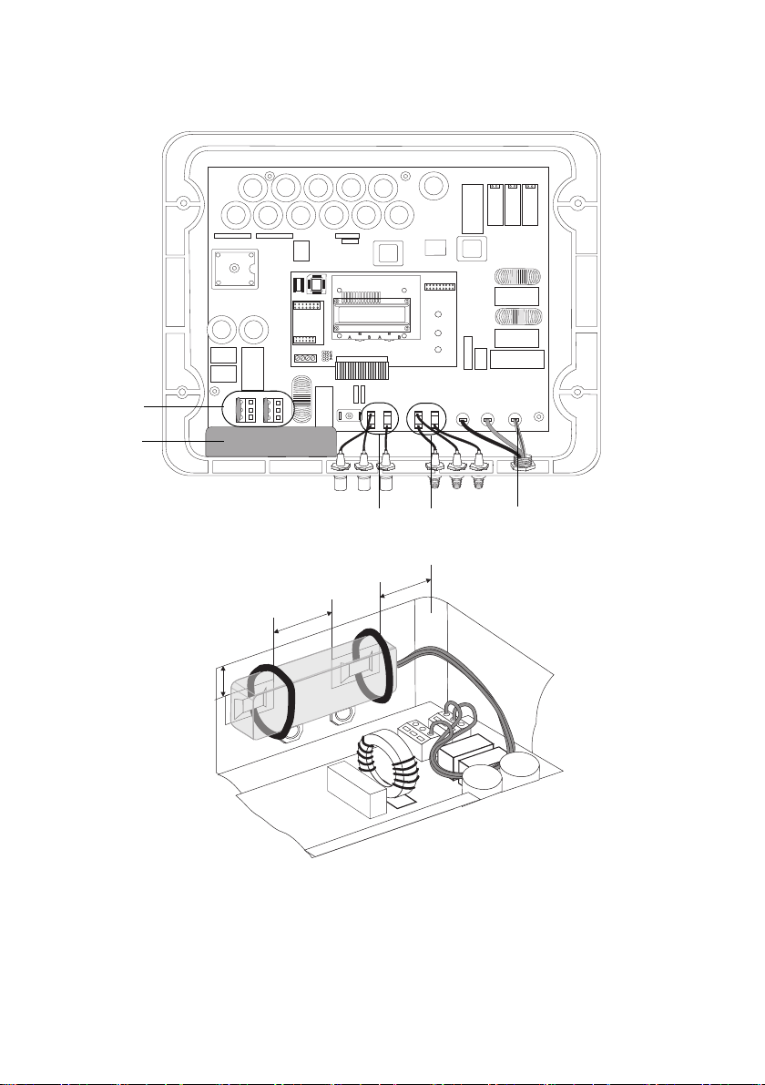
Sunny Boy / Sunny Mini Central SMA Solar Technology AG
1
2
3
4
5
5
0
m
m
2
0
m
m
20 mm
Sunny Boy 3300 / 3800
96 ESHV-IXX103013

SMA Solar Technology AG Sunny Boy / Sunny Mini Central
1
2
3
4
5
1
1
0
m
m
2
0
m
m
20 mm
Sunny Mini Central 4600A / 5000A / 6000A / 7000HV
ESHV-IXX103013 97


4."4PMBS5FDIOPMPHZ"(
XXX4."EF
 Loading...