


MULTICLUSTER BOX 12
Table of contents
 Loading...
Operating Manual
MULTICLUSTER BOX 12
MC-BOX-12-3-20-BE-en-10 | Version 1.0 ENGLISH

Legal Provisions SMA Solar Technology AG
Legal Provisions
The information contained in this document is the property of SMA Solar Technology AG. Publishing its content, either
partially or in full, requires the written permission of SMA Solar Technology AG. Any internal company copying of the
document for the purposes of evaluating the product or its correct implementation is allowed and does not require
permission.
SMA Warranty
You can download the current warranty conditions from the Internet at www.SMA-Solar.com.
Trademarks
All trademarks are recognized, even if not explicitly identified as such. A lack of identification does not mean that a
product or symbol is not trademarked.
The BLUETOOTH
marks by SMA Solar Technology AG is under license.
®
Modbus
is a registered trademark of Schneider Electric and is licensed by the Modbus Organization, Inc.
QR Code is a registered trademark of DENSO WAVE INCORPORATED.
®
Phillips
Torx
and Pozidriv® are registered trademarks of Phillips Screw Company.
®
is a registered trademark of Acument Global Technologies, Inc.
®
word mark and logos are registered trademarks owned by Bluetooth SIG, Inc. and any use of these
SMA Solar Technology AG
Sonnenallee 1
34266 Niestetal
Germany
Tel. +49 561 9522-0
Fax +49 561 9522-100
www.SMA.de
E-mail: info@SMA.de
© 2004 to 2015 SMA Solar Technology AG. All rights reserved.
2 MC-BOX-12-3-20-BE-en-10 Operating Manual

SMA Solar Technology AG Table of Contents
Table of Contents
1 Information on this Document. . . . . . . . . . . . . . . . . . . . . . . . . . . . . . . . . . . . . . . . . . . . . . . . . . . . . 5
1.1 Validity . . . . . . . . . . . . . . . . . . . . . . . . . . . . . . . . . . . . . . . . . . . . . . . . . . . . . . . . . . . . . . . . . . . . . . . . . . . . . . 5
1.2 Target Group . . . . . . . . . . . . . . . . . . . . . . . . . . . . . . . . . . . . . . . . . . . . . . . . . . . . . . . . . . . . . . . . . . . . . . . . . 5
1.3 Additional Information . . . . . . . . . . . . . . . . . . . . . . . . . . . . . . . . . . . . . . . . . . . . . . . . . . . . . . . . . . . . . . . . . . 5
1.4 Symbols . . . . . . . . . . . . . . . . . . . . . . . . . . . . . . . . . . . . . . . . . . . . . . . . . . . . . . . . . . . . . . . . . . . . . . . . . . . . . 5
1.5 Typographies . . . . . . . . . . . . . . . . . . . . . . . . . . . . . . . . . . . . . . . . . . . . . . . . . . . . . . . . . . . . . . . . . . . . . . . . . 6
1.6 Nomenclature. . . . . . . . . . . . . . . . . . . . . . . . . . . . . . . . . . . . . . . . . . . . . . . . . . . . . . . . . . . . . . . . . . . . . . . . . 6
2 Safety . . . . . . . . . . . . . . . . . . . . . . . . . . . . . . . . . . . . . . . . . . . . . . . . . . . . . . . . . . . . . . . . . . . . . . . . 7
2.1 Intended Use . . . . . . . . . . . . . . . . . . . . . . . . . . . . . . . . . . . . . . . . . . . . . . . . . . . . . . . . . . . . . . . . . . . . . . . . . 7
2.2 Safety Information . . . . . . . . . . . . . . . . . . . . . . . . . . . . . . . . . . . . . . . . . . . . . . . . . . . . . . . . . . . . . . . . . . . . . 9
3 Scope of Delivery. . . . . . . . . . . . . . . . . . . . . . . . . . . . . . . . . . . . . . . . . . . . . . . . . . . . . . . . . . . . . . 10
4 Product Description . . . . . . . . . . . . . . . . . . . . . . . . . . . . . . . . . . . . . . . . . . . . . . . . . . . . . . . . . . . . 11
4.1 Multicluster Box . . . . . . . . . . . . . . . . . . . . . . . . . . . . . . . . . . . . . . . . . . . . . . . . . . . . . . . . . . . . . . . . . . . . . . 11
4.2 Grounding in the Multicluster System. . . . . . . . . . . . . . . . . . . . . . . . . . . . . . . . . . . . . . . . . . . . . . . . . . . . . . 12
4.3 Type Label . . . . . . . . . . . . . . . . . . . . . . . . . . . . . . . . . . . . . . . . . . . . . . . . . . . . . . . . . . . . . . . . . . . . . . . . . . 13
5 Installation . . . . . . . . . . . . . . . . . . . . . . . . . . . . . . . . . . . . . . . . . . . . . . . . . . . . . . . . . . . . . . . . . . . 14
5.1 Storing the Multicluster Box . . . . . . . . . . . . . . . . . . . . . . . . . . . . . . . . . . . . . . . . . . . . . . . . . . . . . . . . . . . . . 14
5.2 Requirements for Mounting. . . . . . . . . . . . . . . . . . . . . . . . . . . . . . . . . . . . . . . . . . . . . . . . . . . . . . . . . . . . . . 14
5.3 Preparing the Mounting Location . . . . . . . . . . . . . . . . . . . . . . . . . . . . . . . . . . . . . . . . . . . . . . . . . . . . . . . . . 15
5.4 Transport. . . . . . . . . . . . . . . . . . . . . . . . . . . . . . . . . . . . . . . . . . . . . . . . . . . . . . . . . . . . . . . . . . . . . . . . . . . . 16
5.4.1 Transport Options . . . . . . . . . . . . . . . . . . . . . . . . . . . . . . . . . . . . . . . . . . . . . . . . . . . . . . . . . . . . . . . . . . . . . . .16
5.4.2 Transporting and Mounting the Multicluster Box. . . . . . . . . . . . . . . . . . . . . . . . . . . . . . . . . . . . . . . . . . . . . . . .16
6 Electrical Connection . . . . . . . . . . . . . . . . . . . . . . . . . . . . . . . . . . . . . . . . . . . . . . . . . . . . . . . . . . . 17
6.1 Overview of the Connection Area . . . . . . . . . . . . . . . . . . . . . . . . . . . . . . . . . . . . . . . . . . . . . . . . . . . . . . . . 17
6.1.1 Components and Terminals. . . . . . . . . . . . . . . . . . . . . . . . . . . . . . . . . . . . . . . . . . . . . . . . . . . . . . . . . . . . . . . .17
6.1.2 Enclosure Openings in the Floor . . . . . . . . . . . . . . . . . . . . . . . . . . . . . . . . . . . . . . . . . . . . . . . . . . . . . . . . . . . .18
6.2 Installing the Multicluster Box without Grid Connect Box or NA Box. . . . . . . . . . . . . . . . . . . . . . . . . . . . . . 19
6.3 Connecting the Generator . . . . . . . . . . . . . . . . . . . . . . . . . . . . . . . . . . . . . . . . . . . . . . . . . . . . . . . . . . . . . . 19
6.4 Connecting the Utility Grid . . . . . . . . . . . . . . . . . . . . . . . . . . . . . . . . . . . . . . . . . . . . . . . . . . . . . . . . . . . . . . 20
6.5 Connecting the Loads . . . . . . . . . . . . . . . . . . . . . . . . . . . . . . . . . . . . . . . . . . . . . . . . . . . . . . . . . . . . . . . . . . 21
6.6 Connecting the PV System . . . . . . . . . . . . . . . . . . . . . . . . . . . . . . . . . . . . . . . . . . . . . . . . . . . . . . . . . . . . . . 22
6.7 Connecting the Sunny Island Inverters . . . . . . . . . . . . . . . . . . . . . . . . . . . . . . . . . . . . . . . . . . . . . . . . . . . . . 23
6.8 Grounding the Multicluster System. . . . . . . . . . . . . . . . . . . . . . . . . . . . . . . . . . . . . . . . . . . . . . . . . . . . . . . . 23
6.9 Connecting the Control Cables . . . . . . . . . . . . . . . . . . . . . . . . . . . . . . . . . . . . . . . . . . . . . . . . . . . . . . . . . . 24
6.9.1 Assignment of Spring-Cage Terminals . . . . . . . . . . . . . . . . . . . . . . . . . . . . . . . . . . . . . . . . . . . . . . . . . . . . . . . .24
6.9.2 Connecting the Control Cables of the Sunny Island Inverters . . . . . . . . . . . . . . . . . . . . . . . . . . . . . . . . . . . . . .24
6.9.3 Connecting the BatFuse. . . . . . . . . . . . . . . . . . . . . . . . . . . . . . . . . . . . . . . . . . . . . . . . . . . . . . . . . . . . . . . . . . .24
6.9.4 Connecting the Control Cables to the Grid Connect Box . . . . . . . . . . . . . . . . . . . . . . . . . . . . . . . . . . . . . . . . .25
6.9.5 Connecting the Control Cables to the NA Box . . . . . . . . . . . . . . . . . . . . . . . . . . . . . . . . . . . . . . . . . . . . . . . . .25
6.10 Connecting the Data Cables for Measurement Signals and Communication . . . . . . . . . . . . . . . . . . . . . . . 26
6.11 Mounting the Kick Plates . . . . . . . . . . . . . . . . . . . . . . . . . . . . . . . . . . . . . . . . . . . . . . . . . . . . . . . . . . . . . . . 26
Operating Manual MC-BOX-12-3-20-BE-en-10 3

Table of Contents SMA Solar Technology AG
7 Preparing the Multicluster System for Commissioning . . . . . . . . . . . . . . . . . . . . . . . . . . . . . . . .27
8 Disconnecting the Multicluster Box and Multicluster System . . . . . . . . . . . . . . . . . . . . . . . . . . .28
9 Periodic Actions. . . . . . . . . . . . . . . . . . . . . . . . . . . . . . . . . . . . . . . . . . . . . . . . . . . . . . . . . . . . . . . .29
9.1 Disassembling the Protective Cover . . . . . . . . . . . . . . . . . . . . . . . . . . . . . . . . . . . . . . . . . . . . . . . . . . . . . . . 29
9.2 Mounting the Protective Cover. . . . . . . . . . . . . . . . . . . . . . . . . . . . . . . . . . . . . . . . . . . . . . . . . . . . . . . . . . . 30
9.3 Inserting the Cables . . . . . . . . . . . . . . . . . . . . . . . . . . . . . . . . . . . . . . . . . . . . . . . . . . . . . . . . . . . . . . . . . . . 31
9.3.1 Inserting Power and Control Cables . . . . . . . . . . . . . . . . . . . . . . . . . . . . . . . . . . . . . . . . . . . . . . . . . . . . . . . . .31
9.3.2 Inserting Data Cables . . . . . . . . . . . . . . . . . . . . . . . . . . . . . . . . . . . . . . . . . . . . . . . . . . . . . . . . . . . . . . . . . . . .32
9.4 Connection to Spring-Cage Terminals . . . . . . . . . . . . . . . . . . . . . . . . . . . . . . . . . . . . . . . . . . . . . . . . . . . . . 34
9.4.1 Connecting Power Cables to Spring-Cage Terminals . . . . . . . . . . . . . . . . . . . . . . . . . . . . . . . . . . . . . . . . . . . .34
9.4.2 Connecting Control Cables to Spring-Cage Terminals . . . . . . . . . . . . . . . . . . . . . . . . . . . . . . . . . . . . . . . . . . .35
10 Maintenance . . . . . . . . . . . . . . . . . . . . . . . . . . . . . . . . . . . . . . . . . . . . . . . . . . . . . . . . . . . . . . . . . .36
10.1 Inspection of Residual-Current Devices . . . . . . . . . . . . . . . . . . . . . . . . . . . . . . . . . . . . . . . . . . . . . . . . . . . . 36
10.2 Maintenance Work every 12 Months . . . . . . . . . . . . . . . . . . . . . . . . . . . . . . . . . . . . . . . . . . . . . . . . . . . . . 37
11 Decommissioning . . . . . . . . . . . . . . . . . . . . . . . . . . . . . . . . . . . . . . . . . . . . . . . . . . . . . . . . . . . . . .39
11.1 Disassembling the Multicluster Box . . . . . . . . . . . . . . . . . . . . . . . . . . . . . . . . . . . . . . . . . . . . . . . . . . . . . . . 39
11.2 Disposing of the Multicluster Box. . . . . . . . . . . . . . . . . . . . . . . . . . . . . . . . . . . . . . . . . . . . . . . . . . . . . . . . . 39
12 Technical Data. . . . . . . . . . . . . . . . . . . . . . . . . . . . . . . . . . . . . . . . . . . . . . . . . . . . . . . . . . . . . . . . .40
13 Multicluster Technology Terms . . . . . . . . . . . . . . . . . . . . . . . . . . . . . . . . . . . . . . . . . . . . . . . . . . .44
14 Contact. . . . . . . . . . . . . . . . . . . . . . . . . . . . . . . . . . . . . . . . . . . . . . . . . . . . . . . . . . . . . . . . . . . . . . .46
4 MC-BOX-12-3-20-BE-en-10 Operating Manual
SMA Solar Technology AG 1 Information on this Document
'$1*(5
:$5 1,1*
&$87,21
/05*$&
1 Information on this Document
1.1 Validity
This document is valid for the device type MC-BOX-12.3-20 (Multicluster Box 12).
1.2 Target Group
The activities described in this document must only be performed by qualified persons. Qualified persons must have the
following skills:
• Training in how to deal with the dangers and risks associated with installing and operating electrical devices and
batteries
• Training in the installation and commissioning of electrical devices
• Knowledge of and adherence to the local standards and directives
• Knowledge of and compliance with this document and all safety information
1.3 Additional Information
Links to additional information can be found at www.SMA-Solar.com.
Document title Document type
GRID CONNECT BOX 12 Operating manual
NA BOX 12 Operating manual (document only available in German)
SUNNY ISLAND 3.0M / 4.4M / 6.0H / 8.0H Installation manual
BATFUSE- B.01 / B.03 Operating manual
1.4 Symbols
Symbol Explanation
Indicates a hazardous situation which, if not avoided, will result in death or serious injury
Indicates a hazardous situation which, if not avoided, can result in death or serious injury
Indicates a hazardous situation which, if not avoided, can result in minor or moderate injury
Indicates a situation which, if not avoided, can result in property damage
Information that is important for a specific topic or goal, but is not safety-relevant
☐ Indicates a requirement for meeting a specific goal
☑ Desired result
✖ A problem that might occur
Operating Manual MC-BOX-12-3-20-BE-en-10 5

1 Information on this Document SMA Solar Technology AG
1.5 Typographies
Typography Use Example
bold • Display messages
• Parameters
•Terminals
•Slots
• Elements to be selected or
entered
> • Links several elements to be
selected
[Button/Key] • Button on device to be selected
or pressed
• Connect the neutral conductor to the
spring-cage terminal N at terminal X102:4.
–
•Press the [TEST] button on each
residual-current device in the Multicluster
Box.
1.6 Nomenclature
Complete designation Designation in this document
Multicluster Box 12 Multicluster Box
Grid Connect Box 12 Grid Connect Box
NA Box 12 NA Box
6 MC-BOX-12-3-20-BE-en-10 Operating Manual
SMA Solar Technology AG 2 Safety
2 Safety
2.1 Intended Use
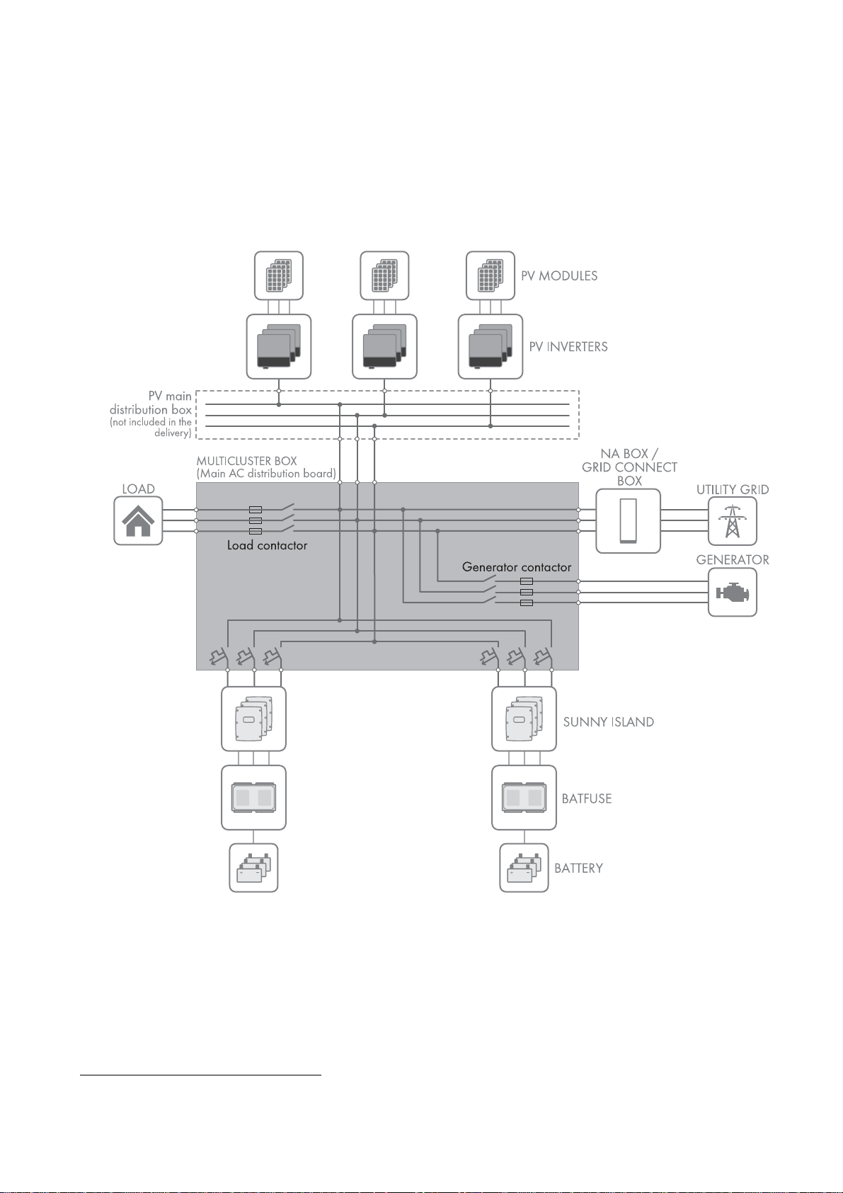
The Multicluster Box is the main AC distribution board in a multicluster system. The multicluster system forms an AC grid
and is made up of several three-phase clusters. Three Sunny Island inverters are connected in parallel on the DC side of
each cluster. The multicluster system can be set up with a stand-alone grid (as an off-grid system) or with increased
self-consumption and battery-backup function (as a battery-backup system).
Figure1: Circuitry principle of a Multicluster Box
The Multicluster Box is not suitable for supplying life-sustaining medical devices. A power outage must not lead to
personal injury.
Cables with copper wires must be used for the installation of the Multicluster Box.
Do not exceed the maximum AC connection power of the Multicluster Box.
Regarding interference immunity the product is suitable for EMC environment A, and regarding EMC emissions it is
suitable for EMC environment B* .
* in accordance with IEC 61439-1:2011
Operating Manual MC-BOX-12-3-20-BE-en-10 7

2 Safety SMA Solar Technology AG
Only a generator may be connected directly to the Multicluster Box. To connect the utility grid in addition to the
generator, it is necessary to install either a Grid Connect Box or an NA Box between the utility grid and the
Multicluster Box (for intended use of the Grid Connect Box / NA Box see operating manual of the Grid Connect Box /
NA Box).
The Multicluster Box is designed for connection to TN-S, TN-C-S and TT systems:
• If only the Multicluster Box is used, the multicluster system must be grounded outside the Multicluster Box on the
generator side (see Section6.8, page23).
• If the Multicluster Box is used together with an NA Box, the utility grid can be a TN-S, TN-C-S or TT system
(see operating manual of the NA Box). No additional grounding measures are required.
• If the Multicluster Box is used together with the Grid Connect Box, remember that the all-pole disconnection can be
deactivated on the Grid Connect Box (see operating manual of the Grid Connect Box). If the all-pole disconnection
on the Grid Connect Box is deactivated, the utility grid must be configured as a TN-C-S system (see Section4.2,
page12).
The Multicluster Box must only be operated in conjunction with Sunny Island 6.0H / 8.0H inverters with software
release 3.5 or higher. Always take the maximum AC connection power and the permitted inverter combinations into
account.
• Only inverters of the same device type must be installed in a cluster.
• Different clusters may be equipped with inverters of different device types.
All work on the product must only be performed using appropriate tools and in compliance with the ESD protection
regulations.
Suitable personal protective equipment has to be worn by all persons working on or with the product.
The Multicluster Box is designed for use at altitudes of up to 3,000 m above mean sea level. If you wish to use the
Multicluster Box at elevations above 3,000 m, contact the SMA Service Line (see Section14, page46).
The product is suitable exclusively for use in weather-protected outdoor areas and in indoor areas. Only operate the
product at temperatures between − 25°C and +60°C.
Use this product only in accordance with the information provided in the enclosed documentation and with the locally
applicable standards and directives. Any other application may cause personal injury or property damage. Alterations
to the product, e.g., modifications or conversions, are only permitted with the express written permission of
SMA Solar Technology AG. Unauthorized alterations will void guarantee and warranty claims and in most cases
terminate the operating license. SMA Solar Technology AG shall not be held liable for any damage caused by such
alterations.
Any use of the product other than that described in the Intended Use section does not qualify as appropriate.
The enclosed documentation is an integral part of this product. Keep the documentation in a convenient place for future
reference and observe all instructions contained therein.
The type label must remain permanently attached to the product.
8 MC-BOX-12-3-20-BE-en-10 Operating Manual

SMA Solar Technology AG 2 Safety
'$1*(5
&$87,21
&$87,21
2.2 Safety Information
This section contains safety information that must be observed at all times when working on or with the product.
To prevent personal injury or property damage and to ensure long-term operation of the product, read this section
carefully and observe all safety information at all times.
Danger to life due to electric shock
High voltages are present in the Multicluster Box and the multicluster system. Touching live components results in death
or serious injury due to electric shock.
• Disconnect the Multicluster Box and multicluster system from all voltage sources before carrying out any work on
the Multicluster Box (see Section8, page28).
• Always operate the Multicluster Box with its protective cover in place.
• All work on the Multicluster Box must be carried out by qualified persons only.
• Do not touch any live components in the Multicluster Box or any other devices of the multicluster system.
Risk of injury if the Multicluster Box tips over
The Multicluster Box is heavy and may tip over if not properly fastened to the support surface. This can result in crushing
injuries.
• After installation, attach the Multicluster Box to the support surface.
Risk of burns due to hot components
Components and terminals inside the Multicluster Box can get hot during operation. Touching hot components can
cause burns.
• Always operate the Multicluster Box with its protective cover in place.
• Prior to removing the protective cover, let the Multicluster Box cool down.
Operating Manual MC-BOX-12-3-20-BE-en-10 9
3 Scope of Delivery SMA Solar Technology AG
3 Scope of Delivery
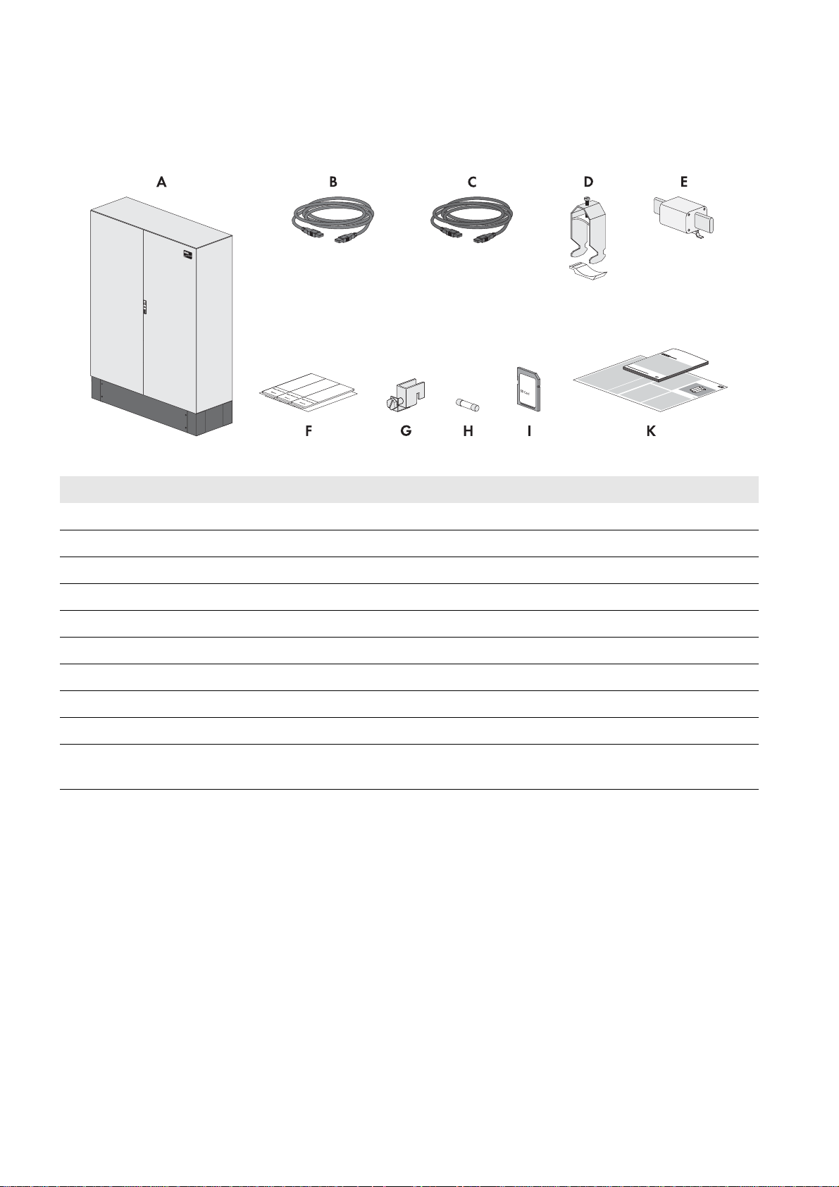
Check the scope of delivery for completeness and any externally visible damage. Contact your distributor if the scope of
delivery is incomplete or damaged.
Figure2: Components included in the scope of delivery
Position Quantity Designation
A 1 Multicluster Box
B 1 Data cable for communication (5 m, black)
C 3 Data cable for measurement and control signals (5 m, red)
D 14 Cable clamp with counter sleeve (22 mm to 28 mm)
E 3 LV/HRC size 1 fuse link, 200 A
F 1 Set of non-woven adhesive labels for cable designation
G 4 Terminal incl. screws for connecting the protective conductors
H 3 Fuse link 1 A, tripping characteristics: gG
I 1 SD memory card with firmware version 3.5 or higher
K 1 Operating manual, circuitry overview, quick reference guide for the Sunny Island
inverter
10 MC-BOX-12-3-20-BE-en-10 Operating Manual
SMA Solar Technology AG 4 Product Description
4 Product Description
4.1 Multicluster Box
The Multicluster Box is an SMA multicluster technology device for off-grid systems, battery-backup systems and systems
for increased self-consumption. The Multicluster Box is a main AC distribution board to which you can connect up to four
clusters. Each three-phase cluster is made up of three DC-side, parallel-switched Sunny Island 6.0H / 8.0H inverters with
software release 3.5 or higher. Functions of the Multicluster Box include:
• Main AC distribution board for Sunny Island inverters, one generator, one load and one PV system
• Load shedding
• Automatic bypass and reverse current monitoring for the generator
• Active anti-islanding
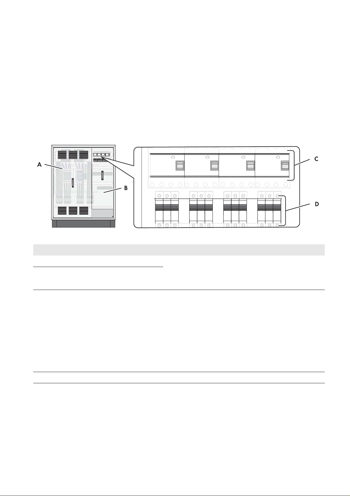
Figure3: Multicluster Box with cabinet door open
Position Designation Explanation
A Protective cover Prevent inadvertent contact with live components during
BProtective cover
C Residual-current device Protects against electric shock and is always used in addition to
D Circuit breakers To protect the power cables of the Sunny Island inverters
operation and thus protect from electric shocks. When the
Multicluster Box is in operation, the protective covers must
always be mounted.
existing protective measures such as insulation or protective
grounding. As soon as a dangerous touch voltage occurs, the
residual-current device disconnects the loads at all poles.
This is achieved by means of a summation current transformer in
the residual-current device which detects the electric currents in
the conductors L1, L2, L3 and N. In the normal operating state,
the sum of these currents equals zero. Under fault conditions a
differential current is formed which trips the residual-current
device.
Operating Manual MC-BOX-12-3-20-BE-en-10 11
4 Product Description SMA Solar Technology AG
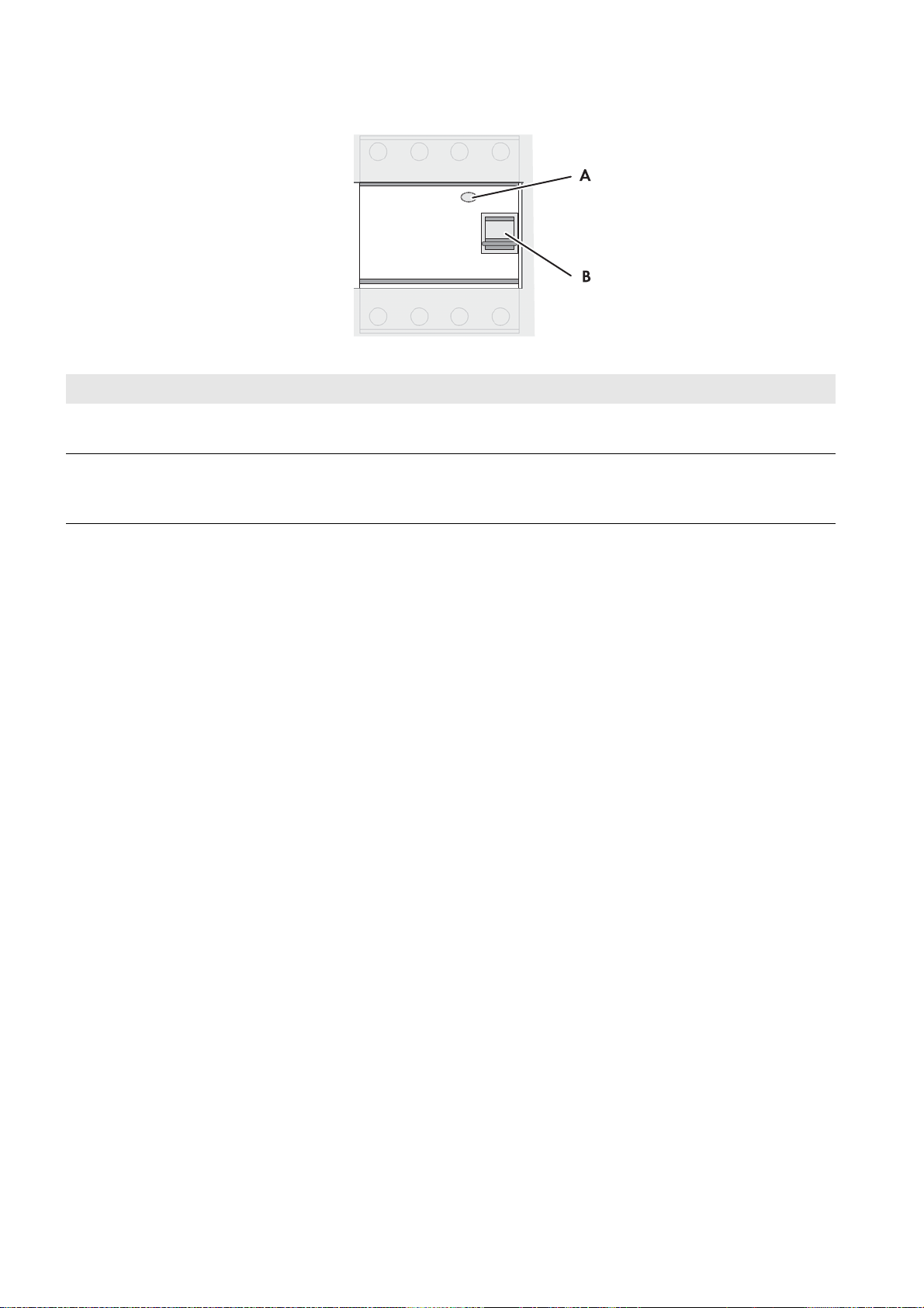
Residual-current device
Figure4: Overview of the residual-current device
Position Designation Explanation
A Test button The functionality of the residual-current device must be tested
regularly (see Section10.1, page36).
B Switch lever Top position: ON - residual-current device is switched on.
Bottom position: OFF - residual-current device has tripped or
is switched off.
4.2 Grounding in the Multicluster System
With TN-S, TN-C-S and TT systems, the neutral conductor must be grounded for protection against indirect contact with
live components. The following options for grounding the neutral conductor are available in the multicluster system:
• If the multicluster system i s using a generator a s grid-forming source, the multicluster system must be grounded outside
the Multicluster Box on the generator side.
• If the multicluster system is connected to the utility grid, it is grounded via the utility grid when in parallel grid
operation. However, in case of grid failure, the multicluster system must disconnect from the utility grid. For this
disconnection, either only the line conductors are disconnected, or in case of all-pole disconnection, the line
conductors and the neutral conductor.
With all-pole disconnection, the multicluster system with line conductors and neutral conductor are disconnected from the
utility grid in the event of grid failure. This disconnection does not ground the neutral conductor in the grid of the
multicluster system. Therefore, in multicluster systems with all-pole disconnection, the grounding contactor of the
Multicluster Box must ground the neutral conductor in the event of grid failure. The grounding contactor ensures the
necessary protection in case of indirect contact with live components. The grounding contactor is in fail-safe design.
If the neutral conductor of the multicluster system is connected to the utility grid, no further grounding is permitted in the
electricity grid of the multicluster system. Therefore, if the multicluster system is connected to the utility grid via NA Box or
Grid Connect Box the grounding contactor of the Multicluster Box deactivates the connection between neutral conductor
and ground potential.
If the Grid Connect Box is used, the all-pole disconnection can be deactivated (see operating manual of the
Grid Connect Box). Deactivation of all-pole disconnection is only possible if the utility grid is configured as a TN-C-S
system. The multicluster system may not be operated on a TT or TN-S grid.
12 MC-BOX-12-3-20-BE-en-10 Operating Manual
SMA Solar Technology AG 4 Product Description
4.3 Type Label
The type label clearly identifies the product. The type label is located on the right-hand side of the enclosure. You will find
the following information on the type label:
• Address of SMA Solar Technology AG
• Device type (Model)
• Serial number (Serial No.)
• Device-specific characteristics
You will require the information on the type label to use the product safely and when seeking customer support from the
SMA Service Line.
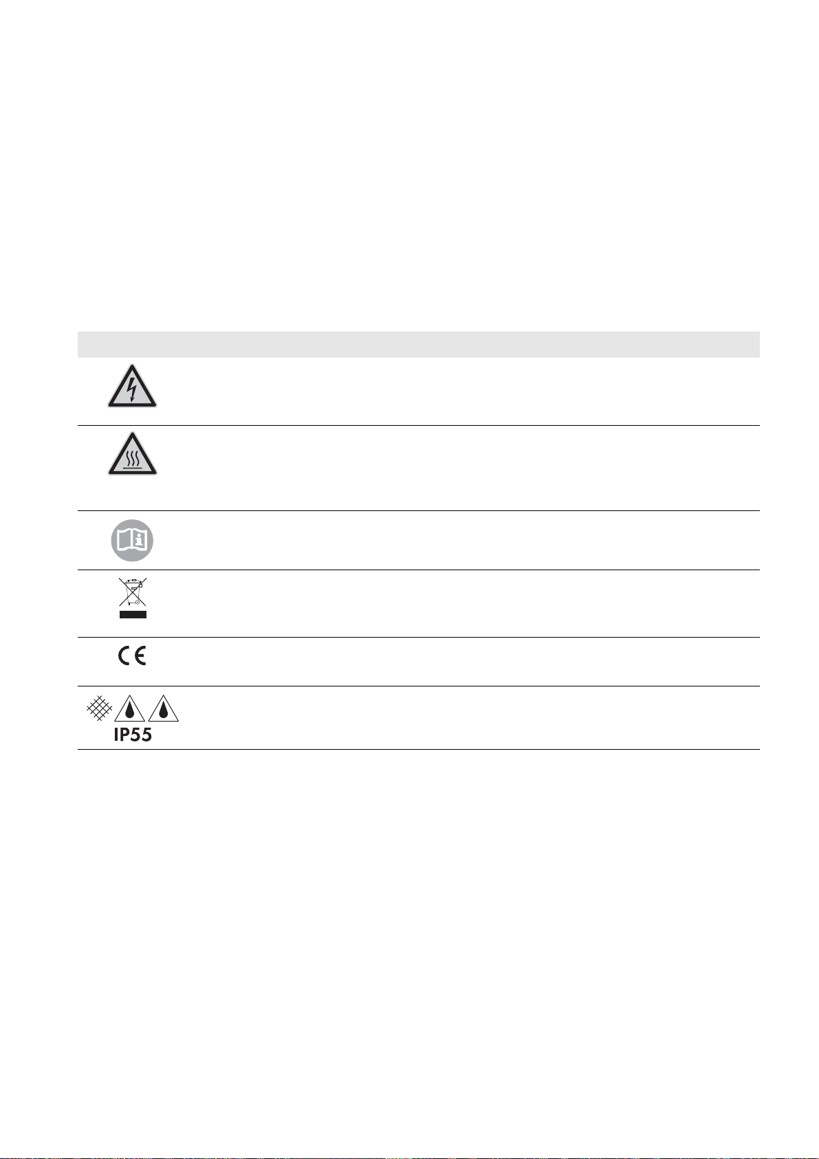
Symbols on the Type Label
Symbol Explanation
Danger to life due to high voltages
The product operates at high voltages. All work on the product must be carried out by qualified
persons only.
Risk of burns due to hot surfaces.
The product can get hot during operation. Avoid contact during operation. Allow the product to cool
down sufficiently before carrying out any work. Wear personal protective equipment such as safety
gloves.
Observe the documentation.
Observe all documentation supplied with the product.
WEEE designation
Do not dispose of the product together with household waste but in accordance with the locally
applicable disposal regulations for electronic waste.
CE marking
The product complies with the requirements of the applicable EU directives.
Degree of protection
The product is protected against interior dust deposits and water jets from all angles.
Operating Manual MC-BOX-12-3-20-BE-en-10 13
5 Installation SMA Solar Technology AG
200 mm200 mm
SM
A
200 mm
5 Installation
5.1 Storing the Multicluster Box
• Store the Multicluster Box in a dry place with an ambient temperature range between − 25°C and +60°C.
5.2 Requirements for Mounting
Optimum mounting location
The ambient temperature influences the tripping threshold of the circuit breakers for the Sunny Island inverters.
The higher the temperature, the earlier the circuit breakers will trip. At high ambient temperatures, the derating
function of the Sunny Island inverters inhibits premature tripping of the circuit breakers.
• To ensure optimum operation, mount and install the Multicluster Box and the Sunny Island inverters at the same
location.
Mounting Location
☐ A firm, even support surface, e.g., a concrete foundation, must be available for mounting.
☐ The mounting location must be suitable for the weight and dimensions of the Multicluster Box (see Section12
"Technical Data", page40).
☐ The mounting location must be clear and safely accessible at all times without the need for any auxiliary equipment.
☐ The Multicluster Box must be mounted without hindrance of access to the disconnection devices.
☐ All local requirements concerning minimum passage widths and escape routes must be observed.
☐ Climatic conditions must be met (see Section12 "Technical Data", page40).
☐ The mounting location must be below 3,000 m above MSL. If you wish to use the Multicluster Box at elevations
above 3,000 m, contact the SMA Service Line (see Section14, page46).
Minimum Clearances
Figure5: Minimum clearances
☐ There must be sufficient space at the mounting location to ensure compliance with the minimum clearances.
☐ There must be a distance of at least 300 mm between the Multicluster Box and the Grid Connect Box or NA Box.
This will ensure adequate heat dissipation.
14 MC-BOX-12-3-20-BE-en-10 Operating Manual
SMA Solar Technology AG 5 Installation
:$5 1,1*
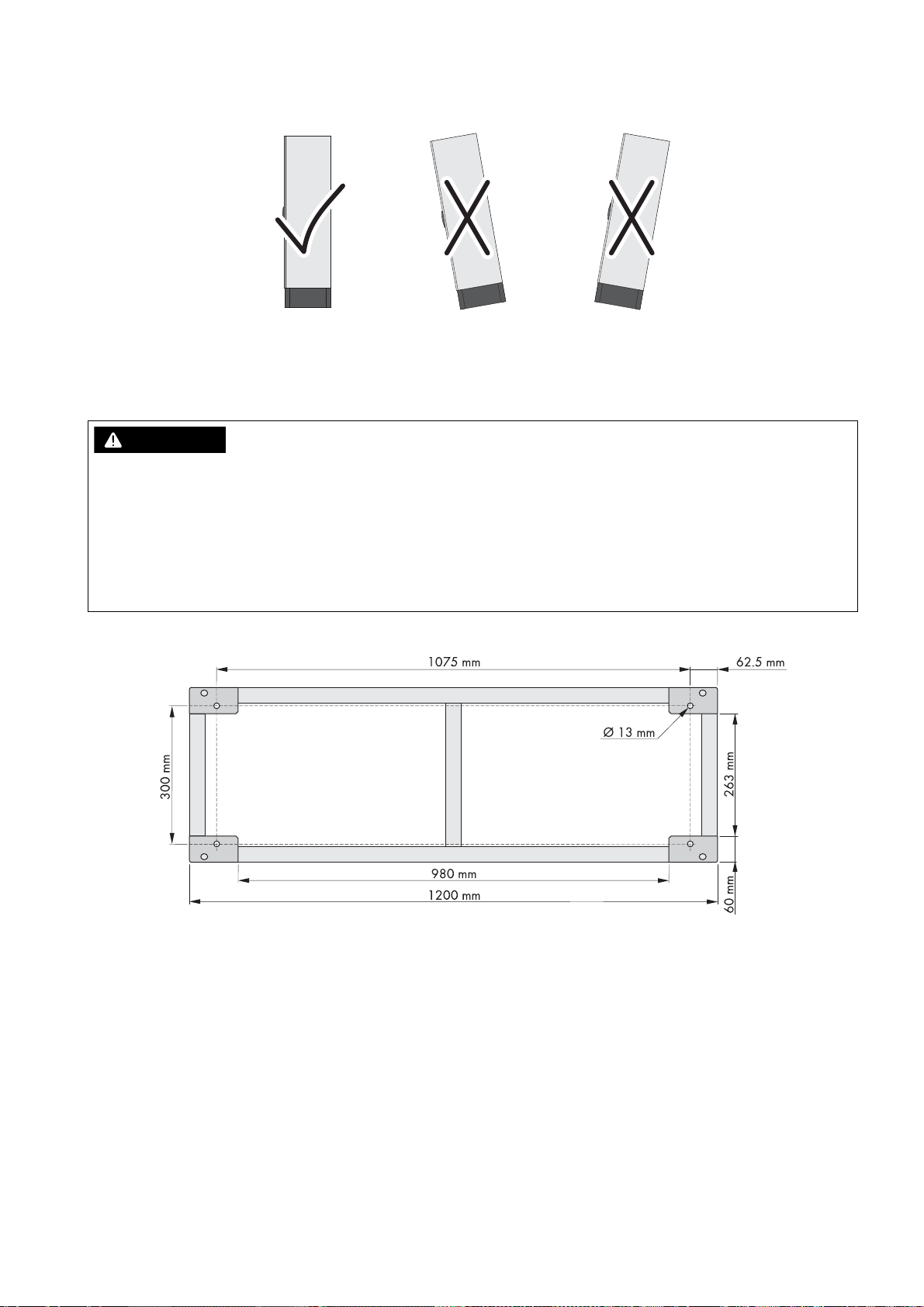
Mounting position
Figure6: Permitted and prohibited mounting positions
☐ The mounting location must allow compliance with the permitted mounting position.
5.3 Preparing the Mounting Location
Danger to life due to fire or explosion
Despite careful construction, electronic devices can cause fires if they are not installed properly. Contact with flammable
materials allows the fire to spread. This can result in death or serious injury.
• Do not install the Multicluster Box on flammable construction materials.
• Do not install the Multicluster Box in areas containing flammable substances or objects.
• Do not install the Multicluster Box in potentially explosive atmospheres.
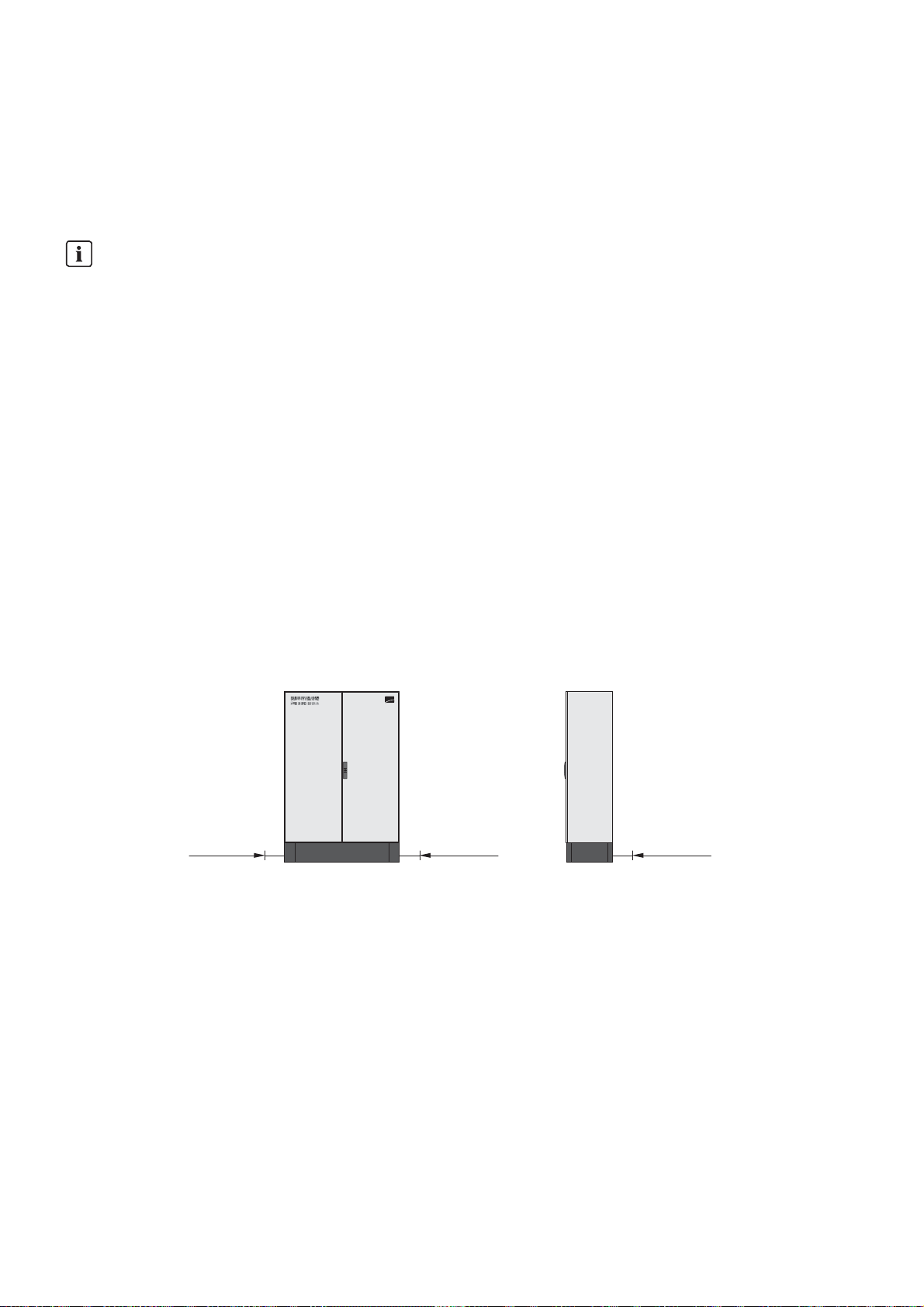
Dimensions of the drill holes for fixing the Multicluster Box:
Figure7: Outside base measurements and dimensions of the drill holes
Additionally required mounting material (not included in the scope of delivery):
☐ 4 suitable screw anchors to fasten the Multicluster Box to the support surface
Procedure:
1. On the mounting surface, mark the position of the four drill holes for attaching the base.
2. Drill holes at the marked positions.
3. Insert screw anchors.
Operating Manual MC-BOX-12-3-20-BE-en-10 15
Loading...