

Skil 4240,4380,4280 Operating/safety Instructions Manual

IMPORTANT: IMPORTANT : IMPORTANTE:
Read Before Using Lire avant usage Leer antes de usar
Operating/Safety Instructions
Consignes de fonctionnement/sécurité
Instrucciones de funcionamiento y seguridad
4240
4280
4380
For English Version
Version française
Versión en español
See page 2 Voir page 13 Ver la página 24
1-877-SKIL999 (1-877-754-5999) www
.skil.com
Call Toll Free for
Consumer Information
& Service Locations
Pour obtenir des informations
et les adresses de nos centres
de service après-vente,
appelez ce numéro gratuit
Llame gratis para
obtener información
para el consumidor y
ubicaciones de servicio
SM 1619X02133 12-06 12/12/06 2:30 PM Page 1

-
2
-
Work Area
Keep your work area clean and well lit.
Cluttered benches and dark areas invite
accidents.
Do not operate power tools in explosive
atmospheres, such as in the presence of
flammable liquids, gases, or dust.
Power
tools create sparks which may ignite the dust
or fumes.
Keep by-standers, children, and visitors
away while operating a power tool.
Distractions can cause you to lose control.
Electrical Safety
Double Insulated tools are equipped with a
polarized plug (one blade is wider than the
other.) This plug will fit in a polarized outlet
only one way. If the plug does not fit fully
in the outlet, reverse the plug. If it still does
not fit, contact a qualified electrician to
install a polarized outlet. Do not change
the plug in any way.
Double Insulation
eliminates the need for the three wire
grounded power cord and grounded power
supply system.
Before plugging in the tool, be
certain the outlet voltage supplied is within the
voltage marked on the nameplate. Do not use
“AC only” rated tools with a DC power supply.
Avoid body contact with grounded
surfaces such as pipes, radiators, ranges
and refrigerators
. There is an increased risk
of electric shock if your body is grounded.
If
operating the power tool in damp locations is
unavoidable, a Ground Fault Circuit Interrupter
must be used to supply the power to your tool.
Electrician’s rubber gloves and footwear will
further enhance your personal safety.
Don't expose power tools to rain or wet
conditions
. Water entering a power tool will
increase the risk of electric shock.
Do not abuse the cord. Never use the cord
to carry the tools or pull the plug from an
outlet. Keep cord away from heat, oil, sharp
edges or moving parts. Replace damaged
cords immediately.
Damaged cords increase
the risk of electric shock.
When operating a power tool outside, use
an outdoor extension cord marked "W-A"
or "W."
These cords are rated for outdoor use
and reduce the risk of electric shock. Refer to
“Recommended sizes of Extension Cords” in
the Accessory section of this manual.
Personal Safety
Stay alert, watch what you are doing and
use common sense when operating a
power tool. Do not use tool while tired or
under the influence of drugs, alcohol, or
medication.
A moment of inattention while
operating power tools may result in serious
personal injury.
Dress properly. Do not wear loose clothing
or jewelry. Contain long hair. Keep your
hair, clothing, and gloves away from
moving parts.
Loose clothes, jewelry, or long
hair can be caught in moving parts. Keep
handles dry, clean and free from oil and
grease.
Avoid accidental starting. Be sure switch
is “OFF” before plugging in
. Carrying tools
with your finger on the switch or plugging in
tools that have the switch “ON” invites
accidents.
Remove adjusting keys or wrenches before
turning the tool “ON”
. A wrench or a key
that is left attached to a rotating part of the tool
may result in personal injury.
Do not overreach. Keep proper footing and
balance at all times
. Proper footing and
balance enables better control of the tool in
unexpected situations.
Use safety equipment. Always wear eye
protection
. Dust mask, non-skid safety
shoes, hard hat, or hearing protection must be
used for appropriate conditions.
Tool Use and Care
Use clamps or other practical way to
secure and support the workpiece to a
stable platform.
Holding the work by hand or
against your body is unstable and may lead to
loss of control.
Do not force tool. Use the correct tool for
your application
. The correct tool will do the
job better and safer at the rate for which it is
designed.
Read and understand all instructions. Failure to follow all instructions
listed below, may result in electric shock, fire and/or serious personal injury.
S
AVE THESE INSTRUCTIONS
!
WARNING
Power Tool Safety Rules
SM 1619X02133 12-06 12/12/06 2:30 PM Page 2

-3-
Safety Rules for Jigsaws
Hold tool by insulated gripping surfaces
when performing an operation where the
cutting tool may contact hidden wiring or
its own cord.
Contact with a "live" wire will
make exposed metal parts of the tool "live"
and shock the operator.
Do not drill, fasten
or break into existing walls or other blind
areas where electrical wiring may exist. If
this situation is unavoidable, disconnect all
fuses or circuit breakers feeding this
worksite.
Never leave the trigger locked "ON".
Before plugging the tool in, check that the
trigger lock is "OFF".
Accidental start-ups
could cause injury.
Be aware of the location and setting of
the switch "Lock-ON" button.
If the switch
is locked "ON" during the use, be ready for
emergency situations to switch it "OFF", by
first pulling the trigger then immediately
releasing it without pressing the "Lock-ON"
button.
Keep hands away from cutting area. Do
not reach under the material being cut.
The proximity of the blade to your hand is
hidden from your sight.
Keep hands from between the gear
housing and saw blade holder.
The
reciprocating blade holder can pinch your
fingers.
Do not use dull or damaged blades. Bent
blade can break easily or cause kickback.
Before starting to cut, turn tool "ON" and
allow the blade to come to full speed.
Tool can chatter or vibrate if blade speed is
too slow at beginning of cut and possibly
kickback.
Always wear safety goggles or eye
protection when using this tool. Use a
dust mask or respirator for applications
which generate dust.
Secure material before cutting. Never
hold it in your hand or across legs.
Small
Do not use tool if switch does not turn it
“ON” or “OFF”.
Any tool that cannot be
controlled with the switch is dangerous and
must be repaired.
Disconnect the plug from the power
source before making any adjustments,
changing accessories, or storing the tool.
Such preventive safety measures reduce the
risk of starting the tool accidentally.
Store idle tools out of reach of children
and other untrained persons.
Tools are
dangerous in the hands of untrained users.
Maintain tools with care. Keep cutting
tools sharp and clean.
Properly maintained
tools, with sharp cutting edges are less likely
to bind and are easier to control. Any
alteration or modification is a misuse and
may result in a dangerous condition.
Check for misalignment or binding of
moving parts, breakage of parts, and any
other condition that may affect the tools
operation. If damaged, have the tool
serviced before using.
Many accidents are
caused by poorly maintained tools. Develop
a periodic maintenance schedule for your
tool.
Use only accessories that are
recommended by the manufacturer for
your model.
Accessories that may be
suitable for one tool, may become hazardous
when used on another tool.
Service
Tool service must be performed only by
qualified repair personnel.
Service or
maintenance performed by unqualified
personnel could result in a risk of injury. For
example: internal wires may be misplaced or
pinched, safety guard return springs may be
improperly mounted.
When servicing a tool, use only identical
replacement parts. Follow instructions in
the Maintenance section of this manual.
Use of unauthorized parts or failure to follow
Maintenance Instructions may create a risk
of electric shock or injury. Certain cleaning
agents such as gasoline, carbon
tetrachloride, ammonia, etc. may damage
plastic parts.
SM 1619X02133 12-06 12/12/06 2:30 PM Page 3

-
4
-
or thin material may flex or vibrate with the
blade, causing loss of control.
Make certain all adjusting screws and the
blade holder are tight before making a
cut.
Loose adjusting screws and holders
can cause the tool or blade to slip and loss of
control may result.
When removing the blade from the tool
avoid contact with skin and use proper
protective gloves when grasping the
blade or accessory.
Accessories may be
hot after prolonged use.
If your tool is equipped with a dust bag,
empty it frequently and after completion of
sawing.
Spontaneous combustion, may in
time, result from mixture of oil or water with
dust particles. Be extremely careful of dust
disposal, materials in fine particle form may be
explosive. Do not throw contents on an open
fire.
Some dust created by
power sanding, sawing,
grinding, drilling, and other construction
activities contains chemicals known to
cause cancer, birth defects or other
reproductive harm. Some examples of
these chemicals are:
• Lead from lead-based paints,
• Crystalline silica from bricks and cement
and other masonry products, and
• Arsenic and chromium from chemically-
treated lumber.
Your risk from these exposures varies,
depending on how often you do this type of
work. To reduce your exposure to these
chemicals: work in a well ventilated area, and
work with approved safety equipment, such
as those dust masks that are specially
designed to filter out microscopic particles.
!
WARNING
SM 1619X02133 12-06 12/12/06 2:30 PM Page 4
-5-
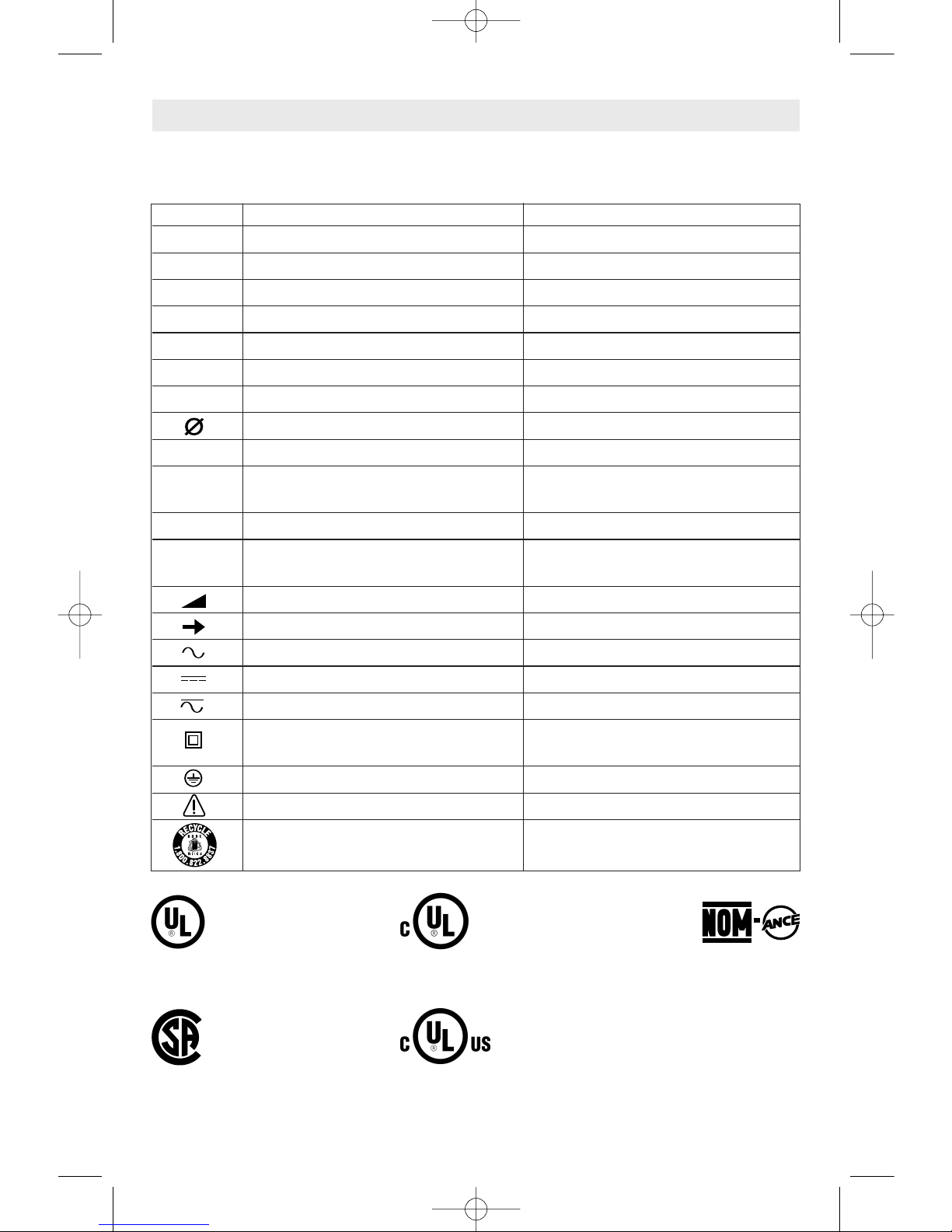
IMPORTANT: Some of the following symbols may be used on your tool. Please study them
and learn their meaning. Proper interpretation of these symbols will allow you to operate the
tool better and safer.
Symbol Name Designation/Explanation
V Volts Voltage (potential)
A Amperes Current
Hz Hertz Frequency (cycles per second)
W Watt Power
kg Kilograms Weight
min Minutes Time
s Seconds Time
Diameter Size of drill bits, grinding wheels, etc.
n
0
No load speed Rotational speed, at no load
.../min Revolutions or reciprocation per minute Revolutions, strokes, surface speed,
orbits etc. per minute
0 Off position Zero speed, zero torque...
1, 2, 3, ... Selector settings Speed, torque or position settings.
I, II, III, Higher number means greater speed
Infinitely variable selector with off Speed is increasing from 0 setting
Arrow Action in the direction of arrow
Alternating current Type or a characteristic of current
Direct current Type or a characteristic of current
Alternating or direct current Type or a characteristic of current
Class II construction Designates Double Insulated
Construction tools.
Earthing terminal Grounding terminal
Warning symbol Alerts user to warning messages
Ni-Cad RBRC seal Designates Ni-Cad battery recycling
program
Symbols
A
0
A
A
0
A
This symbol designates
that this tool is listed by
Underwriters Laboratories.
This symbol designates
that this tool is listed by
the Canadian Standards
Association.
This symbol designates
that this tool is listed to
Canadian Standards by
Underwriters Laboratories.
This symbol
designates
that
this tool
complies
to NOM
Mexican
Standards.
This symbol designates that
this tool is listed by
Underwriters Laboratories,
and listed to Canadian
Standards by Underwriters
Laboratories.
SM 1619X02133 12-06 12/12/06 2:30 PM Page 5
-
6
-
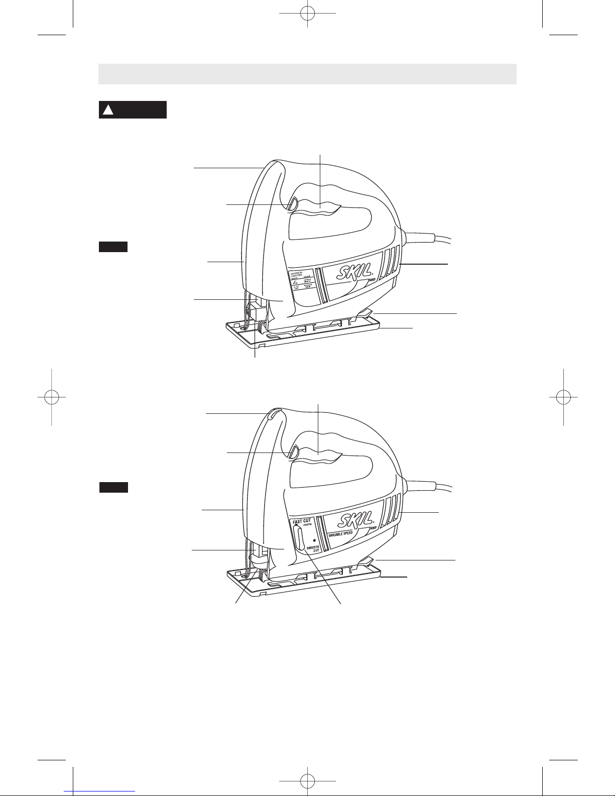
Functional Description and Specifications
Disconnect the plug from the power source before making any
assembly, adjustments or changing accessories
. Such preventive safety
measures reduce the risk of starting the tool accidentally.
!
WARNING
“LOCK-ON”
B
UTTON
VENTILATION
OPENINGS
PLUNGER
BLADE
HOLDER
GEAR
HOUSING
Jigsaws
MAXIMUM CAPACITIES
Model Blade Blade Stroke
No. Thickness Action Length Wood Aluminium Steel
4240 Minimum .8mm - Maximum 1.5mm Standard 5/8" 2" 1/2" 1/4"
4280 Minimum .8mm - Maximum 1.5mm Standard 5/8" 2" 1/2" 1/4"
4380 Minimum .8mm - Maximum 1.5mm Orbital 5/8" 2" 1/2" 1/4"
NOTE: For tool specifications refer to the nameplate on your tool.
VARIABLE SPEED
CONTROL DIAL
“LOCK-ON”
BUTTON
VENTILATION
OPENINGS
FOOT
RELEASE
TAB
PLUNGER
GEAR
HOUSING
TOOL-LESS BLADE
CHANGE COVER
ORBIT CONTROL
LEVER
FOOT
FOOT
RELEASE
TAB
FOOT
TOP OF FRONT
HOUSING
TRIGGER SWITCH
TRIGGER
SWITCH
FIG. 1
FIG. 2
SM 1619X02133 12-06 12/12/06 2:30 PM Page 6
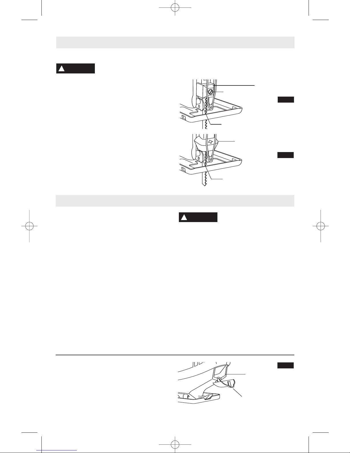
Attaching the Blade
To prevent personal injury,
a
lways disconnect plug from
power source before assembling parts, making
adjustments, or changing blades.
STANDARD MODELS
1. Loosen blade screw in the blade holder and
insert blade to full depth with teeth facing in
direction of cut as shown in (Fig. 3). For use
with both T or U shank jigsaw blades.
2. Securely tighten blade screw on the front of
blade holder with a flat tip screwdriver.
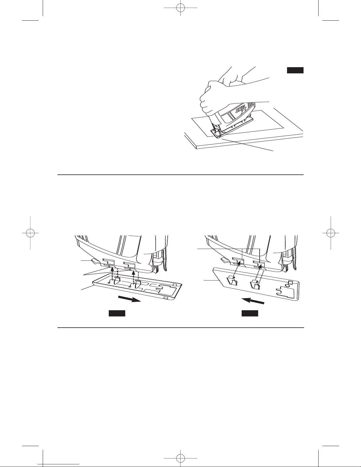
TOOL-LESS MODELS
1. Insert the saw blade (teeth in cutting
direction) until it latches in the plunger
(Fig. 4).
When inserting the saw blade, the back of
the blade must rest in the groove of the
guide roller.
2. To remove blade, lift tool-less blade change
cover up with index and middle fingers and
remove blade. For use with both T or U shank
jigsaw blades.
BLADE STORAGE COMPARTMENT
Your Jigsaw is equipped with a blade storage
area (Fig. 5) on the backside of your saw. To
open door, pull tab on door downward toward
the foot. To close door, lift door upward toward
the tool. Be sure door is closed to prevent
blades from falling out.
-7-
Assembly
VARIABLE SPEED CONTROLLED
TRIGGER SWITCH
(Model 4280 only)
Your tool is equipped with a variable speed trigger
switch. The tool can be turned "ON" or "OFF" by
squeezing or releasing the trigger. The speed
can be adjusted from the minimum to maximum
nameplate SPM by the pressure you apply to the
trigger. Apply more pressure to increase the
speed and release pressure to decrease speed
(Fig. 1).
"LOCK-ON" BUTTON
The "Lock-ON" button, located in the handle of
your tool allows for continuous operation at
maximum SPM without holding the trigger
(Fig. 1).
TO LOCK TRIGGER "ON": squeeze trigger,
depress button and release trigger.
TO UNLOCK THE TRIGGER: squeeze trigger
and release it without depressing the "LockON" button.
If the “Lock-ON” button is
continuously being depressed,
the trigger can not be released.
VARIABLE SPEED DIAL
(Models 4380 only)
Your tool is equipped with a variable speed
dial. The blade stroke rate may
be adjusted
during cutting operation by presetting the dial
on or between any one of the six numbers.
Setting SPM rating (strokes per minute)
1-2
Low stroke
3-4 Medium stroke
5-6 High stroke
PLUNGER SPEED
The stroke rate may be adjusted as described
earlier under “Variable Speed Dial”. The best
results for a particular application is determined
by experience, though as a general rule, slower
speeds are for denser materials and faster
speeds are for soft materials.
!
WARNING
!
WARNING
Operating Instructions
FIG. 5
BLADE
STORAGE
DOOR
TOOL-LESS BLADE
CHANGE COVER
FIG. 4
ROLLER GUIDE
BLADE
HOLDER
BLADE
SCREW
FIG. 3
ROLLER GUIDE
SM 1619X02133 12-06 12/12/06 2:30 PM Page 7
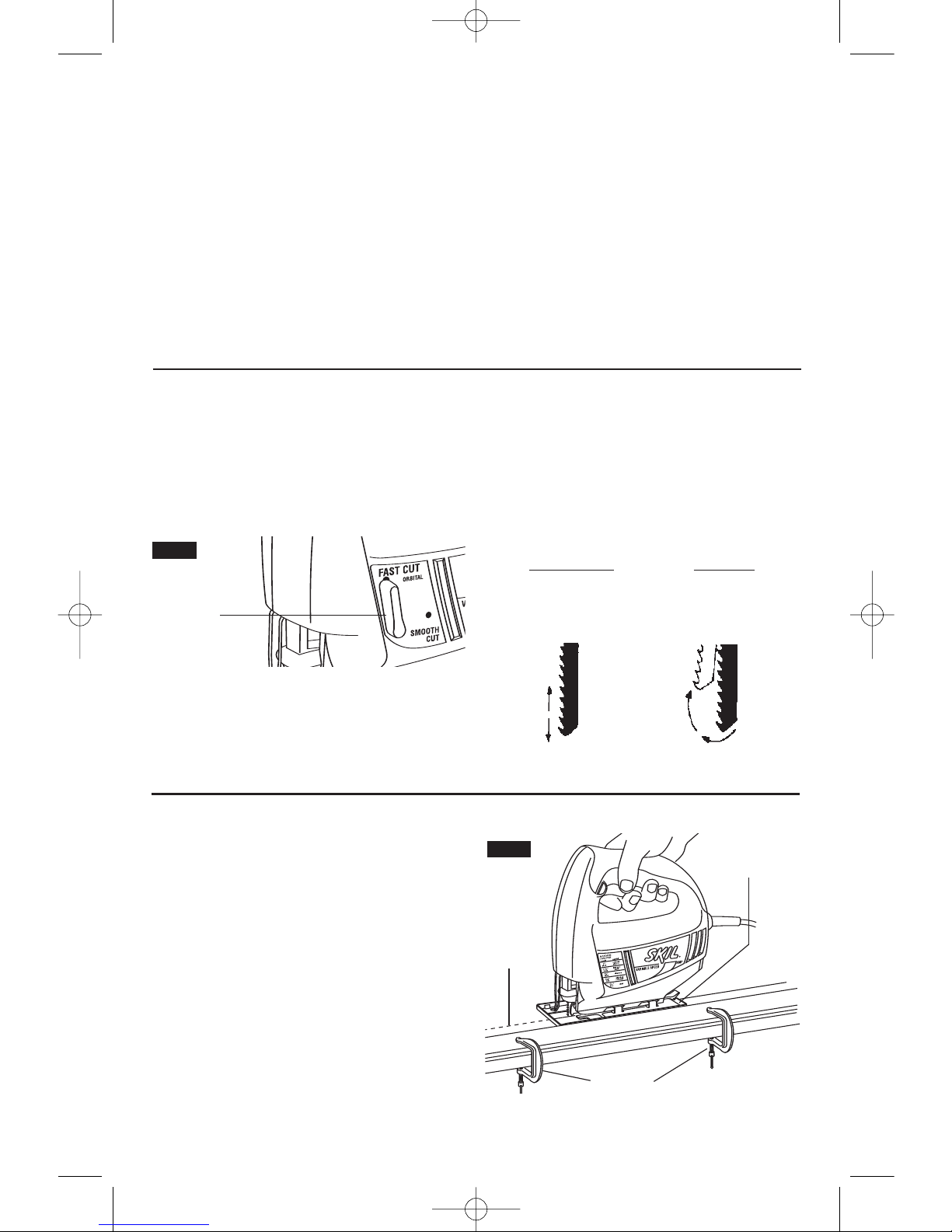
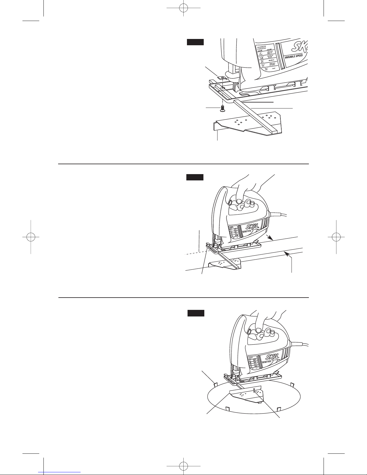
CUTTING WITH A STRAIGHTEDGE
Always use a rough cut blade when possible.
Clamp a straightedge on the work parallel to
the line of cut and flush with the side of the
saw foot. (Either first mark the line of cut and
then position the straightedge parallel and at
the same distance as between the blade and
the side edge of the foot or first mark the side
edge of the foot and then clamp the
straightedge on the mark and parallel to the
cut line Fig. 7)
As you cut, keep the saw foot edge flush
against the straightedge and flat on the
workpiece (Fig. 7).
ORBITAL ACTION
(Model 4380 only)
Orbital Action models, have a lever (Fig. 6)
that will regulate the orbital action from
smooth cut position for normal up and down
motion to maximum orbital action for faster
more aggresive cutting in softer materials.
To activate, turn the lever to fast cut. To
deactivate orbital action turn lever to smooth
cut. When minimal splintering is desired we
recommend using smooth cut position.
Note: In order to reach full orbital action, the
blade must be facing STRAIGHT FORWARD.
Orbital action is not observable when jigsaw
is free running. Jigsaw must be cutting for
orbital action to occur. The speed of cut is
much more apparent in thicker materials such
as 2 by lumber.
SMOOTH CUT
FAST CUT
MILD STEEL SOFT & HARD WOODS
SOFT METALS PLYWOOD
REDUCED SPLINTERING PLASTIC
-
8
-
FIG. 7
LINE
OF
CUT
FOOT AGAINST
STRAIGHT-EDGE
CLAMPS
F
ace the good side of the material down and
secure it in a bench vise or clamp it down.
Draw cutting lines or designs on the side of
the material facing up towards you. Then
place the front edge of the saw foot on the
work and line up the blade with the line to be
cut. Hold the jigsaw firmly, turn it on, and
press down (to keep the saw foot flat against
the work) as you slowly push the saw in the
direction of the cut.
Build up cutting rate gradually, cutting close to
the line (unless you want to leave stock for
f
inish sanding). As you cut you may have to
adjust or relocate the vise or clamps to keep
the work stable. Do not force the saw or the
blade teeth may rub and wear without cutting
and the blade may break. Let the saw do most
of the work. When following curves, cut slowly
so the blade can cut through cross grain. This
will give you an accurate cut and will prevent
the blade from wandering.
Cutting Tips
FIG. 6
ORBIT
CONTROL
LEVER
SM 1619X02133 12-06 12/12/06 2:30 PM Page 8
PLUNGE CUTTING
Plunge cutting is useful and time-saving in
making rough openings in softer materials. It
is not necessary to drill a hole for an inside or
pocket cut. Draw lines for the opening, hold
the saw firmly, tilt it forward so that the toe of
the saw foot rests on the work, but with the
b
lade well clear of the work. Start the motor,
and then very gradually lower the blade.
When it touches, continue pressing down on
the toe of the saw foot slowly pivoting the saw
like a hinge until the blade cuts through and
the foot rests flat on the work. Then saw
ahead on the line of cut line. We do not
recommend plunge cutting with a scroll blade
(Fig. 8).
To make sharp corners, cut up to the corner,
then back up slightly before rounding the
corner. After the opening is complete, go back
to each corner and cut it from the opposite
direction to square it off. Do not try to plunge
cut into hard materials such as steel.
-9-
BEVEL OR ANGLE CUTTING
Disconnect the cord from the power source
and remove the blade.
The foot can be adjusted to cut at 0˚ or 45˚
degrees only on the right side of the tool.
To Adjust foot to 45˚, depress and hold tab on
backside of tool, slide foot firmly toward front
of tool and remove foot from 0˚ notched in
base (Fig. 9).
Align foot with 45˚ notches in base, and slide
foot firmly toward back of tool, and click into
place using the tab (Fig. 10).
FIG. 10FIG. 9
FOOT
RELEASE
TAB
FOOT
0˚ SLOT
45˚
SLOT
FOOT
METAL CUTTING
When cutting metal clamp material down. Be
extra certain that you move the saw along
slowly. Use lower speeds. Do not twist, bend,
or force the blade. If the saw jumps or
bounces, use a blade with finer teeth. If the
blade seems clogged when cutting soft metal,
use a blade with coarser teeth.
For easier cutting, lubricate the blade with a
stick of cutting wax, if available, or cutting oil
when cutting steel. Thin metal should be
sandwiched between two pieces of wood or
tightly clamped on a single piece of wood
(wood on top of the metal). Draw the cut lines
or design on the top piece of wood.
When cutting aluminum extrusion or angle
iron, clamp the work in a bench vise and saw
close to the vise jaws.
When sawing tubing and the diameter is
larger than the blade is deep, cut through the
wall of the tubing and then insert the blade
into the cut rotating the tube as you saw.
TOE OF
FOOT
FIG. 8
SM 1619X02133 12-06 12/12/06 2:30 PM Page 9
-
10
-
STRAIGHT CUTTING
Once the rip fence is attached, measure from
the edge of work to the line of cut, and set edge
guide of rip fence to the same distance and
then securely tighten clamp screw
(Fig. 12).
FIG. 12
DESIRED
WIDTH
CLAMP
SCREW
LINE OF
CUT
RIP FENCE AND CIRCLE CUTTING GUIDE
This accessory is available at an extra cost. It
is used for fast and accurate straight and
circle cutting (Fig. 11).
A
TTACHING RIP FENCE
1
. Insert bar of rip fence through the slots
provided in foot, from either side of foot with
the edge guide facing down (Fig. 11).
2. Thread the clamp screw from under the
foot through the threaded hole in the clamp on
left side of foot, and securely tighten clamp
screw with a screwdriver, to clamp the rip
fence bar in place.
FIG. 11
EDGE GUIDE DOWN
BAR
CLAMP
SCREW
S
LOT
CLAMP
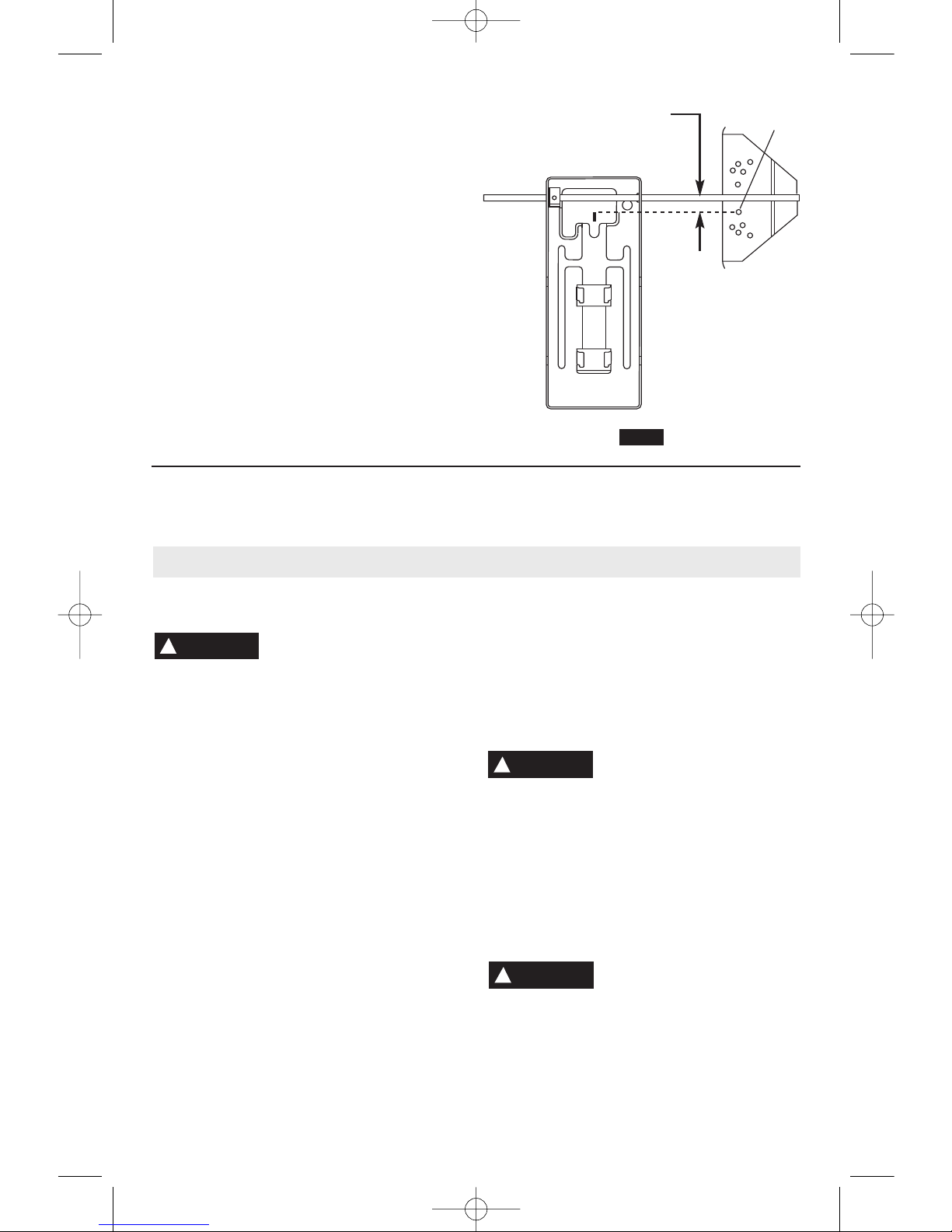
CIRCLE CUTTING
1. Before attaching the rip fence, draw a circle
and drive a finishing nail in the center of circle.
2. Drill or plunge cut near the circles edge,
turn saw off and disconnect the plug from
power source (Fig. 13).
3. Attach rip fence to saw with the edge guide
facing UP. In order for the rip fence to cut a
circle, the nail must be in alignment with the
blade, as shown in (Fig. 14).
4. Measure the distance from the selected
hole to the blade to be equal to the circle
radius.
5. Insert plug into power source, hold the saw
FIG. 13
WEDGE
FINISHING
NAIL
EDGE
GUIDE UP
SM 1619X02133 12-06 12/12/06 2:30 PM Page 10
firmly, squeeze trigger and slowly push the
saw forward. To make a hole, cut from inside
the circle; To make wheels or discs, cut from
t
he outside.
Cutting Tip: Cut slowly so the blade will stay
straight in the cut. Place small wedges in the
cut as shown in Fig. 13, to keep the inner
circle from spreading when near the end of the
cut.
-
11
-
FIG. 14
BLADE MUST BE IN
ALIGNMENT WITH NAIL
NAIL
Service
Preventive maintenance
performed by unauthorized personnel may result in misplacing
of internal wires and components which
could cause serious hazard.
We
recommend that all tool service be performed
by a Skil Factory Service Center or Authorized Skil Service Station.
TOOL LUBRICATION
Your Skil tool has been properly lubricated
and is ready to use. It is recommended that
tools with gears be regreased with a special
gear lubricant at every brush change.
CARBON BRUSHES
The brushes and commutator in your tool
have been engineered for many hours of
dependable service. To maintain peak
efficiency of the motor, we recommend every
two to six months the brushes be examined.
Only genuine Skil replacement brushes
specially designed for your tool should be
used.
BEARINGS
After about 300-400 hours of operation, or at
every second brush change, the bearings
should be replaced at Skil Factory Service
Center or Authorized Skil Service Station.
Bearings which become noisy (due to heavy
load or very abrasive material cutting) should
be replaced at once to avoid overheating or
motor failure.
Cleaning
To avoid accidents always
disconnect the tool from
the power supply before cleaning or
performing any maintenance.
The tool may
be cleaned most effectively with compressed
dry air.
Always wear safety goggles when
cleaning tools with compressed air.
Ventilation openings and switch levers must
be kept clean and free of foreign matter. Do
not attempt to clean by inserting pointed
objects through openings.
Certain cleaning agents
and solvents damage
plastic parts.
Some of these are: gasoline,
carbon tetrachloride, chlorinated cleaning
solvents, ammonia and household
detergents that contain ammonia.
!
WARNING
!
WARNING
Maintenance
!
CAUTION
SM 1619X02133 12-06 12/12/06 2:30 PM Page 11
 Loading...