


Sipex Corporation SP693ACN, SP693ACP, SP693ACT, SP693AEN, SP693AEP Datasheet
...®
SP691A/693A/800L/800M
Low Power Microprocessor Supervisory
with Battery Switch-Over
■Precision 4.65V/4.40V Voltage Monitoring
■200ms Or Adjustable Reset Time
■100ms, 1.6s Or Adjustable Watchdog Time
■60μA Maximum Operating Supply Current
■1.0μA Maximum Battery Backup Current
■0.1μA Maximum Battery Standby Current
■Power Switching
250mA Output in Vcc Mode (0.6Ω) 25mA Output in Battery Mode (5Ω)
■On-Board Gating of Chip-Enable Signals Memory Write-Cycle Completion
6ns CE Gate Propagation Delay
■Voltage Monitor for Power-Fail or Low Battery
■Backup-Battery Monitor
■RESET Valid to Vcc=1V
■1% Accuracy Guaranteed (SP800L/800M)
■Pin Compatible Upgrade to MAX691A/693A/ 800L/800M
DESCRIPTION
The SP691A/693A/800L/800M is a microprocessor (μP) supervisory circuit that integrates a myriad of components involved in discrete solutions to monitor power-supply and battery-control functions in μP and digital systems. The SP691A/693A/800L/800M offers complete μP monitoring and watchdog functions. The SP691A/693A/800L/800M is ideal for a low-cost battery management solution and is well suited for portable, battery-powered applications with its supply current of 35μA. The 6ns chip-enable propagation delay, the 25mA current output in battery-backup mode, and the 250mA current output in standard operation also makes the SP691A/693A/800L/800M suitable for larger scale, high-performance equipment.
Part Number |
RESET Threshold |
RESET Accuracy |
PFI Accuracy |
Backup-Battery Switch |
|
|
|
|
|
SP691A |
4.65V |
+125mV |
+4% |
YES |
|
|
|
|
|
SP693A |
4.40V |
+125mV |
+4% |
YES |
|
|
|
|
|
SP800L |
4.65V |
+50mV |
+1% |
YES |
|
|
|
|
|
SP800M |
4.40V |
+50mV |
+1% |
YES |
|
|
|
|
|
SP691A DS/04 |
SP691A/693A/800L/800M Low Power Microprocessor Supervisor with Battery Switch-Over © Copyright 2000 Sipex Corporation |
1

ABSOLUTE MAXIMUM RATINGS
These are stress ratings only and functional operation of the device at these ratings or any other above those indicated in the operation sections of the specifications below is not implied. Exposure to absolute maximum rating conditions for extended periods of time may affect reliability.
Terminal Voltages (with respect to GND) |
|
|
VCC....................................................................................... |
|
-0.3V to +6V |
VBATT..................................................................................... |
|
-0.3V to +6V |
All Other Inputs........................................................ |
-0.3V to (VCC +0.3V) |
|
Input Currents |
|
|
VCC Peak........................................................................................... |
|
1.0A |
VCC Continuous............................................................................. |
|
250mA |
VBATT Peak.................................................................................... |
|
250mA |
VBATT Continuous............................................................................ |
|
25mA |
GND, BATT ON............................................................................ |
|
100mA |
All Other Inputs.............................................................................. |
|
25mA |
Enhanced ESD Specifications........................ |
+4kV Human Body Model |
|
Power Dissipation Per Package |
|
|
16-pin PDIP (derate 14.3mW/OC above +70OC)....................... |
1150mW |
|
16-pin Narrow SOIC (derate 13.6mW/OC above 70OC)............ |
1090mW |
|
16-pin Wide SOIC (derate 11.2mW/OC above 70OC)................. |
900mW |
|
Storage Temperature.................................................... |
-65OC to +150OC |
|
Lead Temperature (soldering,10 sec)......................................... |
|
+300OC |
SPECIFICATIONS
VCC = +4.75V to +5.5V for the SP691A/800L, VCC = +4.5V to +5.5V for the SP693A/800M, VBATT = +2.8V, and TAMB = TMIN to TMAX unless otherwise noted. Typical values apply at TAMB=+25OC.
PARAMETERS |
MIN. |
TYP. |
MAX. |
UNITS |
CONDITIONS |
|
|
|
|
|
|
Operating Voltage Range, |
0 |
|
5.5 |
V |
|
VCC or VBATT, NOTE 1 |
|
|
|||
|
|
|
|
|
|
|
|
|
|
|
|
Output Voltage, VOUT |
VCC-0.05 |
VCC-0.015 |
|
|
VCC=4.5V, IOUT=25mA |
in Normal Operating Mode |
VCC-0.3 |
VCC-0.15 |
|
V |
VCC=4.5V, IOUT=250mA |
|
VCC-0.2 |
VCC-0.09 |
|
|
VCC=3.0V, VBATT=2.8V, IOUT=100mA |
|
|
|
|
|
|
VCC-to-VOUT On-Resistance |
|
0.6 |
1.2 |
Ω |
VCC=4.5V |
|
|
0.9 |
2.0 |
|
VCC=3.0V |
|
|
|
|
|
|
VOUT in Battery-Backup Mode |
VBATT-0.3 |
VBATT-0.1 |
|
|
VBATT=4.5V, IOUT=20mA |
|
VBATT-0.25 |
VBATT-0.07 |
|
V |
VBATT=2.8V, IOUT=10mA |
|
VBATT-0.15 |
VBATT-0.05 |
|
|
VBATT=2.0V, IOUT=5mA |
|
|
|
|
|
|
VBATT-to-VOUT On-Resistance |
|
5 |
15 |
Ω |
VBATT=4.5V |
|
|
7 |
25 |
VBATT=2.8V |
|
|
|
10 |
30 |
|
VBATT=2.0V |
|
|
|
|
|
|
Supply Current in Normal |
|
35 |
60 |
μA |
VCC>(VBATT-1V), excluding IOUT |
Operating Mode, IVcc |
|
||||
|
|
|
|
|
|
|
|
|
|
|
|
Supply Current in Battery- |
|
0.001 |
1.0 |
μA |
VCC<(VBATT-1.2V), VBATT=2.8V, excluding IOUT |
Backup Mode, IBATT, NOTE 2 |
|
||||
|
|
|
|
|
|
|
|
|
|
|
|
VBATT Standby Current, IBATT, |
-0.1 |
|
0.02 |
μA |
VCC>(VBATT+0.2V), excluding IOUT |
NOTE 3 |
|
||||
|
|
|
|
|
|
|
|
|
|
|
|
Battery Switchover Threshold |
|
VBATT+0.03 |
|
V |
power-up |
|
|
VBATT-0.03 |
|
power-down |
|
|
|
|
|
||
|
|
|
|
|
|
Battery Switchover Hysteresis |
|
60 |
|
mV |
Peak to Peak |
|
|
|
|
|
|
SP691A DS/04 SP691A/693A/800L/800M Low Power Microprocessor Supervisor with Battery Switch-Over © Copyright 2000 Sipex Corporation
2
SPECIFICATIONS (continued)
VCC = +4.75V to +5.5V for the SP691A/800L, VCC = +4.5V to +5.5V for the SP693A/800M, VBATT = +2.8V, and TAMB = TMIN to TMAX unless otherwise noted. Typical values apply at TAMB=+25OC.
|
PARAMETERS |
MIN. |
TYP. |
MAX. |
UNITS |
CONDITIONS |
|
||||||
|
|
|
|
|
|
|
|
|
|
|
|
|
|
BATT ON Output Low |
|
0.1 |
0.4 |
V |
ISINK=3.2mA |
|
|||||||
Voltage |
|
0.7 |
1.5 |
ISINK=25mA |
|
||||||||
|
|
|
|||||||||||
|
|
|
|
|
|
|
|
|
|
|
|
|
|
BATT ON Output Short |
|
60 |
|
mA |
sink current |
|
|||||||
Circuit Current |
1 |
15 |
100 |
μA |
source current |
|
|||||||
|
|
|
|
|
|
|
|
|
|
|
|
|
|
|
RESET, LOWLINE, AND WATCHDOG TIMER |
|
|
|
|
||||||||
|
|
|
|
|
|
|
|
|
|
|
|
|
|
Reset Threshold Voltage |
4.50 |
4.65 |
4.75 |
|
SP691A |
|
|||||||
|
|
|
|
|
|
|
|
4.25 |
4.40 |
4.50 |
V |
SP693A |
|
|
|
|
|
|
|
|
|
4.60 |
4.65 |
4.70 |
SP800L |
|
|
|
|
|
|
|
|
|
|
|
|
||||
|
|
|
|
|
|
|
|
4.35 |
4.40 |
4.45 |
|
SP800M |
|
|
|
|
|
|
|
|
|
|
|
|
|
|
|
Reset Threshold Hysteresis |
|
15 |
|
mV |
center-to-peak |
|
|||||||
|
|
|
|
|
|
|
|
|
|
|
|
|
|
VCC to RESET Delay |
|
80 |
|
μs |
power down |
|
|||||||
LOWLINE to RESET Delay |
|
800 |
|
ns |
power down |
|
|||||||
|
|
|
|
|
|
|
|
|
|
|
|
|
|
Reset Active Timeout Period |
140 |
200 |
280 |
ms |
power-up |
|
|||||||
|
for the Internal Oscillator |
|
|||||||||||
|
|
|
|
|
|
|
|||||||
|
|
|
|
|
|
|
|
|
|
|
|
|
|
Reset Active Timeout Period |
|
|
|
clock |
|
|
|||||||
|
for the External Clock, |
|
2048 |
|
power-up |
|
|||||||
|
|
|
cycles |
|
|||||||||
NOTE 4 |
|
|
|
|
|
||||||||
|
|
|
|
|
|
||||||||
|
|
|
|
|
|
|
|
|
|
|
|
|
|
Watchdog Timeout Period for |
1.0 |
1.6 |
2.25 |
sec |
long period |
|
|||||||
|
the Internal Oscillator |
70 |
100 |
140 |
ms |
short period |
|
||||||
|
|
|
|
|
|
|
|
|
|
|
|
|
|
Watchdog Timeout Period for |
|
4096 |
|
clock |
long period |
|
|||||||
|
the External Clock, NOTE 4 |
|
1024 |
|
cycles |
short period |
|
||||||
|
|
|
|
|
|
|
|
|
|
|
|
|
|
Minimum Watchdog Input |
100 |
|
|
ns |
VIL=0.8V,VIH=0.75xVCC |
|
|||||||
Pulse Width |
|
|
|
||||||||||
|
|
|
|
|
|
||||||||
|
|
|
|
|
|
|
|
|
|
|
|
|
|
|
|
|
|
Output Voltage |
|
0.004 |
0.3 |
|
ISINK=50μA, VCC=1V, VCC falling |
|
|||
RESET |
|
|
|
||||||||||
|
|
|
|
|
|
|
|
|
0.1 |
0.4 |
V |
ISINK=3.2mA, VCC=4.25V |
|
|
|
|
|
|
|
|
|
3.5 |
|
|
|
ISOURCE=1.6mA, VCC=5V |
|
|
|
|
|
|
|
|
|
|
|
|
|
|
|
|
|
|
|
|
|
|
|
|
|||||
|
RESET |
Output Short-Circuit |
|
7 |
20 |
mA |
output source current |
|
|||||
Current |
|
|
|||||||||||
|
|
|
|
|
|
||||||||
|
|
|
|
|
|
|
|
|
|
|
|
|
|
RESET Output Voltage Low, |
|
0.1 |
0.4 |
V |
ISINK=3.2mA |
|
|||||||
NOTE 5 |
|
|
|||||||||||
|
|
|
|
|
|
||||||||
|
|
|
|
|
|
|
|
|
|
|
|
|
|
|
|
|
Output Voltage |
|
0.1 |
0.4 |
|
ISINK=3.2mA, VCC=4.25V |
|
||||
LOWLINE |
|
V |
|
||||||||||
|
|
|
|
|
|
|
|
3.5 |
|
|
ISOURCE=1μA, VCC=5V |
|
|
|
|
|
|
|
|
|
|
|
|
|
|
||
|
|
|
|
|
|
|
|
|
|
|
|
|
|
|
|
|
Output Short |
|
|
|
|
|
|
||||
LOWLINE |
|
15 |
100 |
μA |
output source current |
|
|||||||
Circuit Current |
|
|
|||||||||||
|
|
|
|
|
|
||||||||
|
|
|
|
|
|
|
|
|
|
|
|
|
|
|
|
Output Voltage |
|
0.1 |
0.4 |
|
ISINK=3.2mA |
|
|||||
WDO |
|
V |
|
||||||||||
|
|
|
|
|
|
|
|
3.5 |
|
|
ISOURCE=500μA, VCC=5V |
|
|
|
|
|
|
|
|
|
|
|
|
|
|
||
|
|
|
|
|
|
|
|
|
|
|
|
|
|
|
|
Output Short-Circuit |
|
|
|
|
|
|
|||||
WDO |
|
3 |
10 |
mA |
output source current |
|
|||||||
Current |
|
|
|||||||||||
|
|
|
|
|
|
||||||||
|
|
|
|
|
|
|
|
|
|
|
|
|
|
|
|
|
|
|
|
|
|
|
|
|
|
|
|
SP691A DS/04 SP691A/693A/800L/800M Low Power Microprocessor Supervisor with Battery Switch-Over © Copyright 2000 Sipex Corporation
3

SPECIFICATIONS (continued)
VCC = +4.75V to +5.5V for the SP691A/800L, VCC = +4.5V to +5.5V for the SP693A/800M, VBATT = +2.8V, and TAMB = TMIN to TMAX unless otherwise noted. Typical values apply at TAMB=+25OC.
|
PARAMETERS |
|
|
MIN. |
TYP. |
|
MAX. |
UNITS |
CONDITIONS |
||||||||||||||||||
|
|
|
|
|
|
|
|
|
|
|
|
|
|
|
|
|
|
|
|
|
|
|
|
|
|
|
|
|
WDI Threshold Voltage, |
|
0.75xVCC |
|
|
|
|
V |
VIH |
||||||||||||||||||
|
NOTE 6 |
|
|
|
|
|
0.8 |
|
VIL |
||||||||||||||||||
|
|
|
|
|
|
|
|
||||||||||||||||||||
|
WDI Input Current |
|
-50 |
|
-10 |
|
|
|
μA |
WDI=0V |
|||||||||||||||||
|
|
|
|
|
|
|
|
|
|
|
|
|
|
|
|
|
|
|
|
20 |
50 |
|
WDI=VOUT |
||||
|
|
|
|
|
|
|
|
|
|
|
|
|
|
|
|
|
|
|
|
|
|
||||||
|
|
|
|
|
|
|
|
|
|
|
|
|
|
|
|
|
|
|
|
|
|
|
|
|
|
|
|
|
POWER-FAIL COMPARATOR |
|
|
|
|
|
|
|
|
|
|
|
|||||||||||||||
|
|
|
|
|
|
|
|
|
|
|
|
|
|
|
|
|
|
|
|
|
|
|
|
|
|
|
|
|
PFI Input Threshold |
|
1.200 |
|
1.25 |
1.300 |
|
V |
SP691A/693A, VCC=5V |
||||||||||||||||||
|
|
|
|
|
|
|
|
|
|
|
|
|
|
|
|
|
|
1.22375 |
|
1.25 |
|
1.26375 |
|
SP800L/800M, VCC=5V |
|||
|
|
|
|
|
|
|
|
|
|
|
|
|
|
|
|
|
|
|
|
|
|
||||||
|
|
|
|
|
|
|
|
|
|
|
|
|
|
|
|
|
|
|
|
|
|
|
|
|
|||
|
|
|
|
|
|
|
|
|
|
|
|
|
|
|
|
|
|
|
|
|
|
|
|
|
|
|
|
|
PFI Leakage Current |
|
|
|
|
+0.01 |
+25 |
|
nA |
|
|
|
|||||||||||||||
|
|
|
|
|
|
|
|
|
|
|
|
|
|
|
|
|
|
|
|
|
|
|
|
|
|
|
|
|
|
|
|
|
|
Output Voltage |
|
|
|
|
0.1 |
0.4 |
|
|
ISINK=3.2mA |
||||||||||||
PFO |
|
|
|
|
V |
||||||||||||||||||||||
|
|
|
|
|
|
|
|
|
|
|
|
|
|
|
|
|
3.5 |
|
|
|
|
|
ISOURCE=1μA, VCC=5V |
||||
|
|
|
|
|
|
|
|
|
|
|
|
|
|
|
|
|
|
|
|
|
|
|
|||||
|
|
|
|
|
|
|
|
|
|
|
|
|
|
|
|
|
|
|
|
|
|
|
|
|
|
|
|
|
|
|
|
Short Circuit Current |
|
|
|
|
60 |
|
|
|
mA |
output sink current |
|||||||||||||
PFO |
|
|
|
|
|
|
|
||||||||||||||||||||
|
|
|
|
|
|
|
|
|
|
|
|
|
|
|
|
|
1 |
|
15 |
100 |
|
μA |
output source current |
||||
|
|
|
|
|
|
|
|
|
|
|
|
|
|
|
|
|
|
|
|
|
|
|
|
|
|
|
|
|
|
|
|
|
|
|
|
|
|
|
|
|
|
|
|
|
|
|
|
|
|
||||||
|
PFI-to- |
PFO |
Delay |
|
|
|
|
25 |
|
|
|
μs |
VOD=15mV |
||||||||||||||
|
|
|
|
|
|
|
|
|
|
|
|
|
|
|
|
|
|
|
|
60 |
|
|
|
VOD=15mV |
|||
|
|
|
|
|
|
|
|
|
|
|
|
|
|
|
|
|
|
|
|
|
|
|
|
||||
|
|
|
|
|
|
|
|
|
|
|
|
|
|
|
|
|
|
|
|
|
|
|
|
|
|
|
|
|
CHIP-ENABLE GATING |
|
|
|
|
|
|
|
|
|
|
|
|||||||||||||||
|
|
|
|
|
|
|
|
|
|
|
|
|
|
|
|
|
|
|
|
|
|
|
|
|
|
|
|
|
|
CEIN |
Leakage Current |
|
|
|
|
+0.005 |
+1 |
|
μA |
disable mode |
|||||||||||||||
|
|
|
|
|
|
|
|
|
|
|
|
|
|
|
|
|
|
|
|
|
|
|
|
|
|
|
|
|
|
|
to |
|
|
|
Resistance, |
|
|
|
|
|
|
|
|
|
|
|
|
||||||||
CEIN |
CEOUT |
|
|
|
|
65 |
150 |
|
Ω |
enable mode |
|||||||||||||||||
|
NOTE 7 |
|
|
|
|
|
|||||||||||||||||||||
|
|
|
|
|
|
|
|
|
|
|
|
|
|||||||||||||||
|
|
|
|
|
|
|
|
|
|
|
|
|
|
|
|
|
|
|
|
|
|
|
|
|
|
|
|
|
|
|
Short-Circuit Current |
|
|
|
|
|
|
|
|
|
|
|
|
||||||||||||
CEOUT |
|
|
|
|
|
|
|
|
|
|
|
|
|||||||||||||||
|
|
|
0.1 |
|
0.75 |
2.0 |
|
mA |
disable mode, CEOUT=0V |
||||||||||||||||||
|
(RESET Active) |
|
|
|
|||||||||||||||||||||||
|
|
|
|
|
|
|
|
|
|
|
|
|
|||||||||||||||
|
|
|
|
|
|
|
|
|
|
|
|
|
|
|
|
|
|
|
|
|
|
|
|
|
|
|
|
|
|
to |
|
|
Propagation |
|
|
|
|
|
|
|
|
|
|
|
|
||||||||||
|
CEIN |
CEOUT |
|
|
|
|
6 |
10 |
|
ns |
50Ω source impedance driver, CLOAD=50pF |
||||||||||||||||
|
Delay, NOTE 8 |
|
|
|
|
|
|||||||||||||||||||||
|
|
|
|
|
|
|
|
|
|
|
|
|
|||||||||||||||
|
|
|
|
|
|
|
|
|
|
|
|
|
|
|
|
|
|
|
|
|
|
|
|
|
|
|
|
|
|
Output Voltage High |
|
3.5 |
|
|
|
|
|
|
VCC=5V, IOUT= 100μA |
||||||||||||||||
|
CEOUT |
|
|
|
|
|
V |
||||||||||||||||||||
|
(RESET Active) |
|
2.7 |
|
|
|
|
|
VCC=0V, VBATT=2.8V, IOUT=1μA |
||||||||||||||||||
|
|
|
|
|
|
|
|
||||||||||||||||||||
|
|
|
|
|
|
|
|
|
|
|
|
|
|
|
|
|
|
|
|
|
|
|
|
|
|
|
|
|
|
|
|
|
|
|
|
|
|
|
|
μs |
|
||||||||||||||
|
RESET to CEOUT Delay |
|
|
|
|
12 |
|
|
|
power-down |
|||||||||||||||||
|
|
|
|
|
|
|
|
|
|
|
|
|
|
|
|
|
|
|
|
|
|
|
|
|
|
|
|
|
INTERNAL OSCILLATOR |
|
|
|
|
|
|
|
|
|
|
|
|||||||||||||||
|
|
|
|
|
|
|
|
|
|
|
|
|
|
|
|
|
|
|
|
|
|
|
|
|
|
|
|
|
OSCIN Leakage Current |
|
|
|
|
0.10 |
+5.0 |
|
μA |
OSCSEL=0V |
|||||||||||||||||
|
|
|
|
|
|
|
|
|
|
|
|
|
|
|
|
|
|
|
|
|
|
|
|
|
|
|
|
|
OSCIN Input Pull-Up Current |
|
|
|
|
10 |
100 |
|
μA |
OSCSEL=VOUT or floating, OSCIN=0V |
|||||||||||||||||
|
|
|
|
|
|
|
|
|
|
|
|
|
|
|
|
|
|
|
|
|
|
|
|
|
|
|
|
|
OSCSEL Input Pull-Up Current |
|
|
|
|
10 |
100 |
|
μA |
OSCSEL=0V |
|||||||||||||||||
|
|
|
|
|
|
|
|
|
|
|
|
|
|
|
|
|
|
|
|
|
|
|
|
|
|
|
|
|
OSCIN Frequency Range |
|
|
|
|
200 |
|
|
|
kHz |
OSCSEL=0V |
||||||||||||||||
|
|
|
|
|
|
|
|
|
|
|
|
|
|
|
|
|
|
|
|
|
|
|
|
|
|
|
|
|
OSCIN External Oscillator |
|
VOUT-0.3 |
VOUT-0.6 |
|
|
|
V |
VIH |
||||||||||||||||||
|
Threshold Voltage |
|
|
|
|
3.65 |
2.0 |
|
VIL |
||||||||||||||||||
|
|
|
|
|
|
|
|||||||||||||||||||||
|
OSCIN Frequency with |
|
|
|
|
2 |
|
|
|
kHz |
OSCSEL=0V, COSC=47pF |
||||||||||||||||
|
External Capacitor |
|
|
|
|
|
|
|
|||||||||||||||||||
|
|
|
|
|
|
|
|
|
|
|
|
|
|||||||||||||||
|
|
|
|
|
|
|
|
|
|
|
|
|
|
|
|
|
|
|
|
|
|
|
|
|
|
|
|
SP691A DS/04 |
SP691A/693A/800L/800M Low Power Microprocessor Supervisor with Battery Switch-Over © Copyright 2000 Sipex Corporation |
4
SPECIFICATIONS (continued)
VCC = +4.75V to +5.5V for the SP691A/800L, VCC = +4.5V to +5.5V for the SP693A/800M, VBATT = +2.8V, and TAMB = TMIN to TMAX unless otherwise noted. Typical values apply at TAMB=+25OC.
NOTE 1: Either VCC or VBATT can go to 0V, if the other is greater than 2.0V.
NOTE 2: The supply current drawn by the SP691A/693A/800L/800M from the battery (excluding IOUT) typically
goes to 5μA when (VBATT - 1V) < VCC < VBATT. In most applications, this is a brief period as VCC falls through this region.
NOTE 3: "+" = battery-discharging current, "-" = battery-charging current.
NOTE 4: Although presented as typical values, the number of clock cycles for the reset and watchdog timeout periods are fixed and do not vary with process or temperature.
NOTE 5: RESET is an open-drain output and sinks current only.
NOTE 6: WDI is internally connected to a voltage divider between VOUT and GND. If unconnected, WDI is driven to 1.6V (typ), disabling the watchdog function.
NOTE 7: The chip-enable resistance is tested with VCC = +4.75V for the SP691A/800L and VCC = +4.5V for the
SP693A/800M. CEIN = CEOUT = VCC/2.
NOTE 8: The chip-enable propagation delay is measured from the 50% point at CEIN to the 50% point at CEOUT.
TYPICAL PERFORMANCE CHARACTERISTICS (TAMB = 25oC, unless otherwise noted)
|
43 |
|
|
VCC = 5V |
|
|
|
|
|
|
|
VBATT = 2.8V |
|
|
|
|
40 |
|
|
|
|
|
|
μA) |
37 |
|
|
|
|
|
|
( |
|
|
|
|
|
|
|
Current |
|
|
|
|
|
|
|
34 |
|
|
|
|
|
|
|
|
|
|
|
|
|
|
|
CC |
31 |
|
|
|
|
|
|
V |
|
|
|
|
|
|
|
|
28 |
|
|
|
|
|
|
|
25 |
|
|
|
|
|
|
|
-60 |
-30 |
0 |
30 |
60 |
90 |
120 |
Temperature (oC)
|
2.5 |
|
|
|
|
|
|
|
|
2.0 |
VCC = 1.6V |
|
|
|
|
|
|
|
VBATT |
= 2.8V |
|
|
|
|
|
|
|
|
|
|
|
|
|
||
μA) |
1.5 |
|
|
|
|
|
|
|
|
|
|
|
|
|
|
|
|
( |
|
|
|
|
|
|
|
|
Current |
1.0 |
|
|
|
|
|
|
|
0.5 |
|
|
|
|
|
|
|
|
BATT |
|
|
|
|
|
|
|
|
|
|
|
|
|
|
|
|
|
V |
|
|
|
|
|
|
|
|
|
0.0 |
|
|
|
|
|
|
|
|
-0.5 |
|
|
|
|
|
|
|
|
-60 |
-30 |
0 |
30 |
60 |
90 |
120 |
150 |
Temperature (oC)
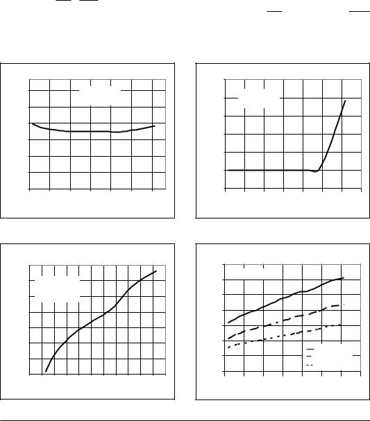
Figure 1. VCC Supply Current vs. Temperature (Normal Operating Mode)
Figure 2. Battery Supply Current vs. Temperature (Battery-Backup Mode)
|
75.0 |
|
|
|
|
|
|
|
Ω) |
70.0 |
VCC = 4.75V |
|
|
|
|
||
|
V |
BATT |
= 2.8V |
|
|
|
|
|
( |
|
|
|
|
|
|
|
|
Resistance |
65.0 |
CE IN = VCC/2 |
|
|
|
|
||
60.0 |
|
|
|
|
|
|
|
|
55.0 |
|
|
|
|
|
|
|
|
-IN |
50.0 |
|
|
|
|
|
|
|
CE |
|
|
|
|
|
|
|
|
|
|
|
|
|
|
|
|
|
|
45.0 |
|
|
|
|
|
|
|
|
40.0 |
|
|
|
|
|
|
|
|
-80 -60 -40 -20 |
0 |
20 40 |
60 |
80 100 120 140 |
|||
Temperature (oC)
Figure 3. Chip-Enable On-Resistance vs. Temperature
|
14 |
|
|
|
|
|
|
|
|
12 |
VCC = 0V |
|
|
|
|
|
|
|
|
|
|
|
|
|
|
|
(Ω) |
10 |
|
|
|
|
|
|
|
8 |
|
|
|
|
|
|
|
|
Resistance |
|
|
|
|
|
|
|
|
6 |
|
|
|
|
|
|
|
|
4 |
|
|
|
|
VBATT = 2V |
|
||
|
2 |
|
|
|
|
|
||
|
|
|
|
|
VBATT = 2.8V |
|
||
|
0 |
|
|
|
|
VBATT = 4.5V |
|
|
|
|
|
|
|
|
|
|
|
|
-60 |
-30 |
0 |
30 |
60 |
90 |
120 |
150 |
Temperature (oC)
Figure 4. VBATT to VOUT On-Resistance vs. Temperature
SP691A DS/04 |
SP691A/693A/800L/800M Low Power Microprocessor Supervisor with Battery Switch-Over © Copyright 2000 Sipex Corporation |
5
TYPICAL PERFORMANCE CHARACTERISTICS (TAMB = 25oC, unless otherwise noted)
|
0.9 |
VCC = 4.5V |
|
|
|
|
|
|
|
|
VBATT = 2.8V |
|
|
|
|
|
|
(Ω) |
0.7 |
|
|
|
|
|
|
|
Resistance |
|
|
|
|
|
|
|
|
0.5 |
|
|
|
|
|
|
|
|
|
0.3 |
|
|
|
|
|
|
|
|
-60 |
-30 |
0 |
30 |
60 |
90 |
120 |
150 |
Temperature (oC)
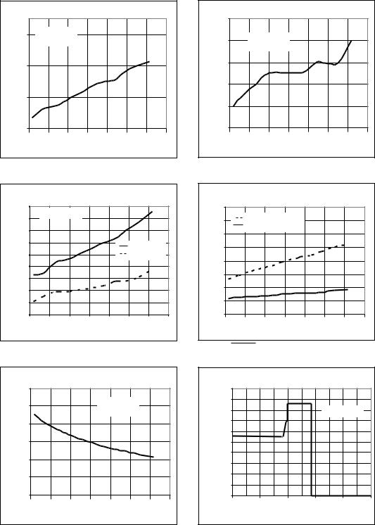
Figure 5. VCC to VOUT On-Resistance vs. Temperature
|
4.69 |
VBATT = 0V |
|
|
|
|
|
|
|
4.68 |
|
|
|
|
|
||
|
|
|
|
|
|
|
|
|
(V) |
4.67 |
|
|
|
|
|
|
|
4.66 |
|
|
|
|
|
|
|
|
Threshold |
|
|
|
|
VCC Rising |
|
||
|
|
|
|
|
|
|||
4.65 |
|
|
|
|
VCC Falling |
|
||
4.64 |
|
|
|
|
|
|
|
|
|
|
|
|
|
|
|
|
|
Reset |
4.63 |
|
|
|
|
|
|
|
4.62 |
|
|
|
|
|
|
|
|
|
4.61 |
|
|
|
|
|
|
|
|
4.60 |
-30 |
0 |
30 |
60 |
90 |
120 |
150 |
|
-60 |
|||||||
Temperature (oC)
Figure 7. Reset Threshold vs. Temperature
|
0.240 |
|
|
|
|
|
|
|
(s) |
0.230 |
|
|
|
VCC = 5V |
|
|
|
|
|
|
VBATT = 2.8V |
|
|
|||
|
|
|
|
|
|
|||
Period |
0.220 |
|
|
|
|
|
|
|
|
|
|
|
|
|
|
|
|
Timeout |
0.210 |
|
|
|
|
|
|
|
0.200 |
|
|
|
|
|
|
|
|
Reset |
0.190 |
|
|
|
|
|
|
|
|
0.180 |
|
|
|
|
|
|
|
|
-60 |
-30 |
0 |
30 |
60 |
90 |
120 |
150 |
Temperature (oC)
|
1.256 |
|
|
|
|
|
|
|
|
1.252 |
VCC = 5V |
|
|
|
|
|
|
|
VBATT |
= 0V |
|
|
|
|
|
|
(V) |
|
|
|
|
|
|
||
|
|
|
|
|
|
|
|
|
PFI Threshold |
1.248 |
|
|
|
|
|
|
|
1.244 |
|
|
|
|
|
|
|
|
1.240 |
|
|
|
|
|
|
|
|
|
|
|
|
|
|
|
|
|
|
1.236 |
|
|
|
|
|
|
|
|
-60 |
-30 |
0 |
30 |
60 |
90 |
120 |
150 |
Temperature (oC)
Figure 6. PFI Threshold vs. Temperature
|
400 |
|
|
|
|
|
|
|
|
350 |
Sourcing VCC = 5V |
|
|
|
|
||
|
300 |
Sinking VCC = 4.25V |
|
|
|
|||
|
|
|
|
|
|
|
|
|
(Ω) |
250 |
|
|
|
|
|
|
|
Resistance |
|
|
|
|
|
|
|
|
200 |
|
|
|
|
|
|
|
|
150 |
|
|
|
|
|
|
|
|
100 |
|
|
|
|
|
|
|
|
|
|
|
|
|
|
|
|
|
|
50 |
|
|
|
|
|
|
|
|
0 |
|
|
|
|
|
|
|
|
-60 |
-30 |
0 |
30 |
60 |
90 |
120 |
150 |
Temperature (oC)
Figure 8. RESET Output Resistance vs. Temperature
|
1.E-04 |
|
|
|
|
|
Scale |
1.E-05 |
|
|
|
|
|
1.E-06 |
|
|
|
VBATT = 2.8V |
|
|
1.E-07 |
|
|
|
|
|
|
Log |
|
|
|
|
|
|
1.E-08 |
|
|
|
|
|
|
(A), |
|
|
|
|
|
|
1.E-09 |
|
|
|
|
|
|
Current |
1.E-10 |
|
|
|
|
|
1.E-11 |
|
|
|
|
|
|
1.E-12 |
|
|
|
|
|
|
BATT |
|
|
|
|
|
|
1.E-13 |
|
|
|
|
|
|
V |
|
|
|
|
|
|
|
1.E-14 |
|
|
|
|
|
|
0 |
1 |
2 |
3 |
4 |
5 |
VCC (V)
Figure 9. Reset Delay vs. Temperature |
Figure 10. Battery Current vs. Input Supply Voltage |
|
|
|
|
SP691A DS/04 |
SP691A/693A/800L/800M Low Power Microprocessor Supervisor with Battery Switch-Over © Copyright 2000 Sipex Corporation |
|
6

TYPICAL PERFORMANCE CHARACTERISTICS (TAMB = 25oC, unless otherwise noted)
|
1000 |
Long Watchdog Timeout Period |
|
||
|
|
|
|
||
|
|
|
Reset Active Timeout Period |
|
|
Watchdog and Reset |
|
100 |
Short Watchdog Timeout Period |
|
|
Timeout Period (s) |
|
|
|
||
10 |
|
|
|
||
1 |
|
VCC = 5V |
|
||
|
|
VBATT = 2.8V |
|||
|
|
|
|
||
|
|
0.1 |
|
|
|
|
|
10 |
100 |
1000 |
10000 |
OSCIN Capacitor (pF)
Figure 11. Watchdog and Reset Timeout Period vs. OSCIN Timing Capacitor (COSC)
|
30 |
|
|
|
|
|
|
|
|
25 |
VCC = 5V |
|
|
|
|
|
|
(μs) |
VBATT = 2.8V |
|
|
|
|
|
||
|
50Ω driver |
|
|
|
|
|
||
Delay |
20 |
|
|
|
|
|
|
|
|
|
|
|
|
|
|
|
|
Propagation |
15 |
|
|
|
|
|
|
|
10 |
|
|
|
|
|
|
|
|
5 |
|
|
|
|
|
|
|
|
|
|
|
|
|
|
|
|
|
|
0 |
|
|
|
|
|
|
|
|
0 |
50 |
100 |
150 |
200 |
250 |
300 |
350 |
Cload (pF)
Figure 12. Chip-Enable Propagation Delay vs. CEOUT Load Capacitance
|
1000 |
|
|
|
Drop (mV) |
100 |
|
|
|
|
|
|
|
|
Voltage |
10 |
|
VCC = 4.5V |
|
|
|
VBATT = 0V |
|
|
|
|
|
Slope = 0.6Ω |
|
|
1 |
|
|
|
|
1 |
10 |
100 |
1000 |
IOUT (mA)
Figure 13. VCC to VOUT vs. Output Current (Normal Operating Mode)
|
1000 |
|
|
|
Drop (mV) |
100 |
|
|
|
|
|
|
|
|
Voltage |
10 |
|
VCC = 4.5V |
|
|
VBATT |
= 0V |
||
|
|
|||
|
|
Slope = 5Ω |
||
|
|
|
||
|
1 |
|
|
|
|
1 |
10 |
100 |
1000 |
IOUT (mA)
Figure 14. VBATT to VOUT vs. Output Current (BatteryBackup Mode)
VCC Reset |
+5V |
Threshold |
0V |
80μs
HI
RESET
LOW
 1.1μs
1.1μs
HI
LOWLINE
LOW
16μs
HI
CEOUT
LOW
Figure 15. VCC to LOWLINE and CEOUT Delay
SP691A DS/04 |
SP691A/693A/800L/800M Low Power Microprocessor Supervisor with Battery Switch-Over © Copyright 2000 Sipex Corporation |
7
 Loading...