


Instruction Manual
and Parts List
Zigzag Sewing Machine
20U
20E
109 / 109C
112 / 112C
309
910
SINGER and the Cameo "S" Design are exclusive trademarks of The Singer Company Limited S.à r.l. or its Affiliates. ©2011 The Singer Company Limited S.à r.l. or its Affiliates. All rights reserved.

Contents
1 |
Safety Instructions |
1 |
|
|
|
1.1 |
Important Safety Instructions |
1 |
|
1.2 |
For Safe Operation |
2 |
|
|
2 |
Product Description and Machine Specification |
3 |
|
|
|
2.1 |
Product Description |
3 |
|
2.2 |
Machine Specification |
4 |
|
|
|
|
|
|
|
|
2.3 |
Motor, Motor Pulley and V-Belt Specifications |
5 |
|
2.4 |
Relationship between Zigzag Bight and Maximum Speed |
5 |
|
|
|
|
|
|
|
3 |
Setup and Adjustment Instructions |
6 |
|
|
3.1 |
Table Cut-Out Drawing |
6 |
|
|
|
|
|
|
|
|
3.2 |
Oil Reservoir Installation |
7 |
|
3.3 |
Belt Cover Installation |
8 |
|
|
|
|
|
|
|
|
3.4 |
Operation panel Installation (for 20E-910 only) |
8 |
|
|
3.5 |
The connecting the connectors to the control box (for 20E-910 only) |
9 |
|
3.6 |
Lubrication |
10 |
|
|
|
|
|
|
|
|
3.7 |
Needle and Thread |
11 |
|
3.8 |
Inserting the Needle |
11 |
|
|
|
|
|
|
|
|
3.9 |
Bobbin Case Attachment |
12 |
|
3.10 |
Bobbin Thread Winding |
13 |
|
|
|
|
|
|
|
|
3.11 |
Bobbin Case Threading and Replacement |
14 |
|
|
3.12 |
Machine Threading |
16 |
|
|
3.13 |
Stitch Length Adjustment (Except 20E-910) |
17 |
|
|
3.14 |
Presser Foot Pressure Adjustment |
17 |
|
|
3.15 |
Needle Thread Tension Adjustment |
18 |
|
|
3.16 |
Thread Take-up Spring Adjustment |
18 |
|
3.17 |
Bobbin Thread Tension Adjustment |
19 |
|
|
|
3.18 |
Needle Position Selector (except 20U-309 and 20E-910) |
19 |
|
|
3.19 |
Stitch Width Regulator (Except 20E-910) |
20 |
|
|
3.20 |
Zigzag Stitch Width Control (Except 20E-910) |
20 |
|
|
3.21 |
Needle Bar Frame Clamp Device |
21 |
|
|
3.22 |
Straight and Zigzag Stitch Fitting (Except 20E-910) |
22 |
|
|
3.23 |
Spool Cap Usage |
23 |
|
|
3.24 |
Thread Anti-Spill Net Usage |
24 |
|
|
3.25 |
Knee Lifter Installation |
24 |
|
|
3.26 |
Fittings for Buttonhole Stitching |
27 |
|
|
3.27 |
Fittings for Hem Sewing |
27 |
|
3.28 Fittings for Zipper and Cord Sewing |
28 |

Contents
4 |
Maintenance |
29 |
4.1 |
Machine Head Cleaning |
29 |
4.2 |
Lubrication |
29 |
4.3 |
Safety Inspection |
29 |
|
|
|
5 |
Troubleshooting |
30 |
6 |
Parts List |
31 |
6.1 |
Face Plate, Arm Top Cover and Arm Side Cover Components |
32 |
6.2 |
Thread Take-up, Arm Shaft and Handwheel Components |
34 |
|
|
|
6.3 |
Needle Bar, Presser Bar and Needle Plate Components |
36 |
6.4 |
Zigzag Triangular Cam and Hook Advancing Crank Components |
38 |
|
|
|
6.5 |
Bight Amplitude, Bight and L-C-R Position Components |
40 |
6.6 |
Arm Shaft (upright) and Rotating Hook Drive Shaft Components |
42 |
|
|
|
6.7 |
Hook and Bobbin Case Components |
44 |
6.8 |
Feed Regulating Dial and Feed Reverse Lever Components |
46 |
6.9 |
Feed Mechanism Components |
48 |
|
|
|
6.10 |
Presser Bar Lifter and Thread Tension Components |
50 |
6.11 |
Feed Mechanism Components for 20E-910 only |
52 |
|
|
|
6.12 |
Needle Bar Vibration Components for 20E-910 only |
54 |
6.13 |
Control system components for 20E-910 only |
55 |
|
|
|
6.14 |
Thread Stand Components |
56 |
6.15 |
Accessories and Attachments |
58 |
|
|
|
6.16 |
Belt Cover Components and Extra Parts |
60 |

1.1
Important Safety Instructions
Important
When using the machine, basic safety procedures must be followed. Read with attention all instructions before using the machine. When using it, understand that all basic safety instructions are not limited to the following items.
Read all instructions, take care of this manual, and use it as reference when necessary.
Safety Instructions
•Before running the machine, make sure all relevant safety specifications are adequate to specifications and technical standards in your country.
•The machine should not be run without its safety devices.
•The machine should only be operated by properly trained personnel.
•For your safety, goggles must be used while running the machine.
•Turn off or unplug the machine when the following situations arise:
•Passing the thread by the needle or replacing the bobbin or looper.
•Replacing the needle, presser foot, throat plate, feed dog and sliding plate.
•When the machine is in maintenance.
•When the operator is not running the machine.
•In case of lubricant oil contact with the eyes or skin, washed the surface with plenty of icy water with a generous amount of cold water. In case of ingestion, seek medical help immediately.
•Repair, fitting or maintenance should only be performed by properly trained personnel.
•Maintenance and repair on electric equipment should only be made by qualified personnel. If any electric device is damaged, the machine should be immediately stopped.
•Before starting the machine in full running, a test must be conducted to assure that machine and operator are able to perform the task.
•The machine should not be placed next to a sound source as an ultrasonic welding machine and other equipment.
•The machine should only be run with the proper electric cable and connectors, and also the adequate grounding.
•The machine should only be used to sew materials as indicated in its instructions manual, and indications of use should be followed.
Singer will not be held responsible for any damage caused by unauthorized changes in the product.
Zigzag Sewing Machine | Instruction Manual and Parts List 1

1.2 
For Safe
Operation
•To avoid the risk of electric shock, do not open the motor wiring box and do not touch the components assembled inside the wiring box.
•To avoid injuries do not run the machine without the belt cover or in case any other safety device is removed.
•To avoid possible injuries keep fingers, head and clothes far from wheel, belt and motor when the machine is running. Nothing should be placed near those parts.
•To avoid injuries never put your fingers next to the rotating hook and the thread take-up lever cover when the machine is running.
•To avoid possible injuries be careful when putting down or lifting the machine head.
•To avoid accident in case of a sudden start of the machine always turn it off when laying it down, or remove the belt cover and the belt.
•If you machine is equipped with a servomotor, it does not make noises while being driven.To avoid a possible accident caused by an unexpected start, be sure the machine is turned off.
•To avoid electrical shock, do not run the machine without proper grounding.
•To minimize the risk of accidents or damage in electric components caused by electric discharge turn the machine off before unplugging it.
•Clean the machine periodically.
Zigzag Sewing Machine | Instruction Manual and Parts List 2
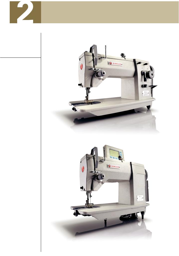
Product Description
and Machine Specification
2.1 |
Zigzag Sewing Machine |
20U series |
Product
Description
20E
Zigzag Sewing Machine | Instruction Manual and Parts List 3

2.2 |
|
|
|
|
|
|
|
|
|
Machine |
|
|
|
|
|
|
|
|
Specification |
|
|
|
|
|
|
|
|
|
|
|
|
|
|
|
|
Table 1 – Machine Specification |
|
|
|
|
|
|
||
|
|
|
|
|
|
|
|
|
|
|
|
|
|
Singer model |
|
|
|
|
|
|
|
|
|
|
|
|
|
|
|
20U-109 / 109C |
20U-112 / 112C |
|
20U-309 |
20E-910 |
|
|
For sewing |
|
|
Light to medium |
|
|
||
|
Stitch type |
Plain zigzag (Straight stitch) |
|
3-step zigzag |
Editable, built-in pattern 100 |
|
||
|
Max. speed[1] |
2,500 rpm |
2,000 rpm |
|
2,500 rpm |
2,000 rpm |
|
|
|
Max. stitch bight |
9.0 mm |
12.0 mm |
|
9.0 mm |
9.0 mm |
|
|
|
Max. stitch length |
|
|
|
3.0 mm |
|
|
|
|
Needle bar stroke |
|
|
|
34.8 mm |
|
|
|
|
Presser bar lift (manual) |
|
|
|
6.35 mm |
|
|
|
|
Presser bar lift (knee lifter) |
|
|
|
9.0 mm |
|
|
|
|
Needle catalog (needle system) |
|
Cat. 1910-05 (135x9) |
|
|
|||
|
Oil |
|
|
|
Singer Oil |
|
|
|
Maximum speed will vary depending on fabric, threads and sewing condition
Zigzag Sewing Machine | Instruction Manual and Parts List 4

2.3
Motor, Motor Pulley and V-Belt Specifications
2.4
Relationship between Zigzag Bight and Maximum Speed
1/3 HP (250W) 4-pole (low speed) clutch motor M type v-belt
Table 2 – Machine Speed vs. Motor Pulley Diameter
|
Machine Speed |
|
|
Motor Pulley Diameter |
|||
|
[spm] |
|
|
|
[mm] |
||
|
|
|
|
|
|
|
|
20U-109 /109C |
20U-112 / 112C |
|
20U-309 |
20E-910 |
50 Hz |
|
60 Hz |
2,500 |
- |
|
2,500 |
- |
130 |
|
105 |
2,000 |
2,000 |
|
2,000 |
2,000 |
105 |
|
85 |
1,800 |
1,800 |
|
1,800 |
1,800 |
90 |
|
75 |
1,500 |
1,500 |
|
1,500 |
1,500 |
80 |
|
65 |
|
|
|
|
|
|
|
|
Table 3 - Relationship between Zigzag Bight and Maximum Speed.
Machine Class |
20U-109 / 109C / 309 |
20U-112 / 112C |
20E-910 |
|||
Zigzag bight |
0 ~ 5.0 mm |
5.0 ~ 9.0 mm |
0 ~ 5.0 mm |
|
5.0 ~ 12.0 mm |
0 ~ 9.0 mm |
Max. speed |
2,500 rpm |
2,000 rpm |
2,000 rpm |
|
1,800 rpm |
2,000 rpm |
|
|
|
|
|
|
|
Zigzag Sewing Machine | Instruction Manual and Parts List 5
Setup and Adjustment Instructions
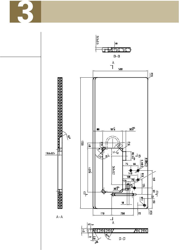
3.1
Table Cut-Out Drawing
This hole for 20E only
Figure 1
Zigzag Sewing Machine | Instruction Manual and Parts List |
6 |
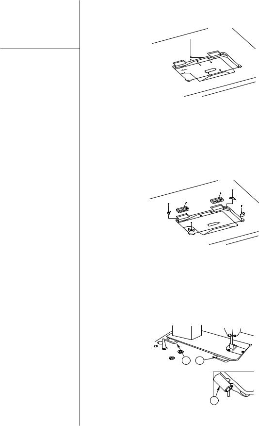
3.2
Oil Reservoir Installation
The oil reservoir should be fixed on the side of the machine table groove by using four nails (Figure 2).
25mm
Figure 2
Two rubber |
seats and two rubber |
using nails, and the other two |
corners for |
supporting the head |
rubber cushion on the hinge side |
portion should be fixed on the |
should be fixed on grooves by |
|
extended portion of the table by |
using nails too (Figure 3). |
|
Figure 3
Two hinges ‘1’ fit into the hole in the |
before the machine head is placed to |
machine bed, and the machine head |
the cushions on the four corners of |
fitted the table hinge's rubber ‘2’, |
the table (Figures 3 and 4). |
21
1
Figure 4
Zigzag Sewing Machine | Instruction Manual and Parts List |
7 |
3.3
Belt Cover Installation
Caution
Switch off the machine.
Set sewing head upright again using both hands.
Danger of crushing between sewing head and table top.
For your safety, do not run the machine without the belt cover.
3.4
Operation Panel Installation (for 20E-910 only)
The machine belt cover
Install the machine belt cover so that the hand wheel and v-belt move freely without interference, and then tighten the screw at this position (see Figure 5).
The motor belt cover
Install the motor belt cover so that motor pulley and v-belt will rotate freely without interference.
Figure 5
Install the operation panel ’1’ to the |
Then the operation panel with the |
bracket ‘2’ by two screws ‘3’. |
bracket is attached into the machine |
|
by setscrew ‘4’. |
1 |
|
|
2 |
|
3 |
|
4 |
Figure 6
Zigzag Sewing Machine | Instruction Manual and Parts List |
8 |
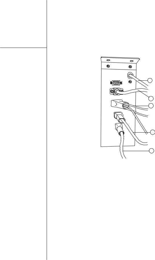
3.5
The connecting the connectors to the control box (for 20E-910 only)
Note
Each connector has the inserting direction. Check the direction and securely insert it.
The sewing machine fails to work if the connectors are not properly inserted.
Installations of the connecting connector refer on Figure 7.
1.Sensor cord connector
2.Feed step motor cord connector
3.Needle vibration step motor cord connector
4.Power supply cord connector
5.Operation panel cord connector
4
5
1
2
3
Figure 7
Zigzag Sewing Machine | Instruction Manual and Parts List |
9 |

3.6
Lubrication
Caution
Switch off the machine.
Set sewing head upright again using both hands.
Danger of crushing between sewing head and table top.
For your safety, do not run the machine without the belt cover.
Important
When you first operate your machine after set up or after an extended period of disuse, oil the machine and run your machine at 1,000 to 1,500 spm for about 10 minutes for the purpose of bread-in.
The rotating hook, and the area at |
Regularly apply one or two drops of |
the under of the needle plate. |
oil to the oil hole at the rotating |
Turn handwheel over toward you |
hook (Oiling point at the Figure 8). |
|
|
until oil hole in the rotating hook |
|
appear in sight. |
|
Figure 8
Remove the face plate and the top |
Apply a small amount of grease to |
cover. |
gear teeth indicated at the 'B'. |
Apply sufficient oil to all oil felt and |
Keep the oil saturated with the oil |
indicate with oiling points shown in |
reservoir felt ‘A’ at the under of the |
Figure 9 |
top cover. |
|
A |
BB
B
Figure 9
Zigzag Sewing Machine | Instruction Manual and Parts List |
10 |
3.7
Needle and Thread
Caution
The power supply should be cut off before attaching the needle.
Selection of the proper needle |
needle and thread sizes to be used |
|||||
depends not only on the machine |
on the various machine models |
|||||
model, but also on the material and |
please refer to the table below. |
|||||
thread used. For selection of proper |
|
|
|
|
||
Table 4 - Needle andThread |
|
|
|
|
|
|
|
|
|
|
|||
Model |
20U-109 / 109C / 112 / 112C / 309, 20E-910 |
|
||||
|
|
|
|
|
|
|
Application |
Light weight |
Medium weight |
|
Mid-heavy weight |
|
|
materials |
|
materials |
|
materials |
|
|
|
|
|
|
|||
Max. thread size (Nm)- |
|
|
|
|
|
|
120 |
|
60 |
|
30 |
|
|
Synthetic* |
|
|
|
|||
|
|
|
|
|
|
|
|
|
|
|
|
|
|
Needle size (1/100mm) |
10 (60) |
12 ~ 16 (80 ~ 100) |
|
18 ~ 19 (110 ~ 120) |
|
|
Needle catalog |
|
|
|
|
|
|
|
|
1910-05 (135x9) |
|
|
||
(Needle system) |
|
|
|
|
||
|
|
|
|
|
|
|
|
|
|
|
|
|
|
* or an equivalent size of other types of thread
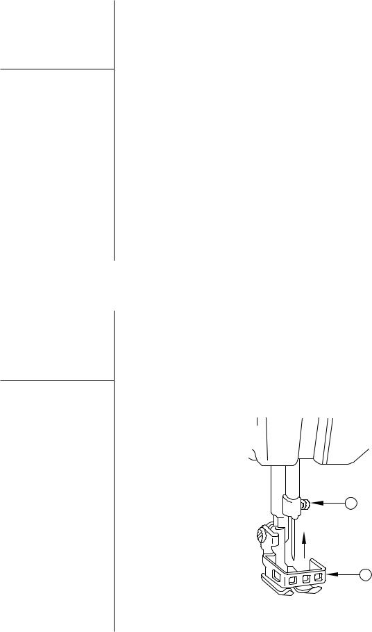
3.8
Inserting the Needle
Caution
Switch off the machine.
Do not operate the machine without the finger guard ‘2’ (see Figure 10)
Use needle Cat. No. 1910-05 needle system (135x9) only.
Raise needle bar to its highest position by turning handwheel toward you.
Loosen needle set screw ‘1’ (see
Figure 10). Insert the needle in the needle bar and push it up as far as it will go.
Make sure its long groove faces toward the front.Tighten needle set screw ‘1’ securely.
1
2
Figure 10
Zigzag Sewing Machine | Instruction Manual and Parts List |
11 |

3.9
Bobbin Case Attachment
Caution
Switch off the machine.
Do not operate the machine with throat plate left open.
Follow as shown in Figure 11.
1.Open bed slide.
2.Raise latch ‘1’.
3.Lift out bobbin case ‘2’.
1
2
Figure 11
Zigzag Sewing Machine | Instruction Manual and Parts List |
12 |
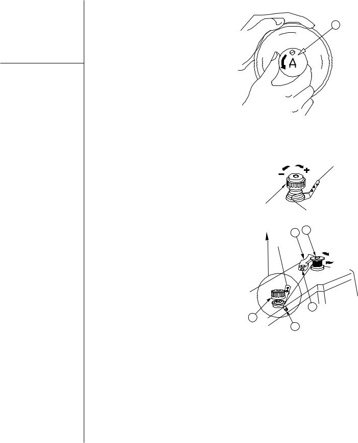
3.10
Bobbin
Thread
Winding
Caution
Do not guide or hold thread when winding the bobbin.
Stop motion of needle by loosening stop-motion screw ‘1’. Hold handwheel with left hand and turn stopmotion screw toward you with right hand. (See Figure 12).
Place bobbin on bobbin winder spindle ‘3’ and pushing it on as far as it will go.
‘1’ adjustment.
‘+’ direction: Increase tension
‘-‘ direction: Decrease tension
Push latch ‘2’ in the direction indicated by arrow ‘A’, then start the machine.
Bobbin winder spindle ‘3’ is rotate in the direction indicated by arrow ‘B’.
To adjust the amount of thread on bobbin, loosen screw ‘4’ on latch ‘2’ and swing the latch ‘2’ away from you or toward you, as required.
For more thread on bobbin, swing latch ‘2’ away from you.
For less thread on bobbin, swing latch ‘2’ toward you.
If thread winds unevenly on bobbin, loosen screw ‘5’ and move pretension ‘1’ up or down, as required, and tighten screw ‘5’.
1
Figure 12
Threading the pre-tension for bobbin winding
23
A
B
4
1
5
Figure 13
Zigzag Sewing Machine | Instruction Manual and Parts List |
13 |
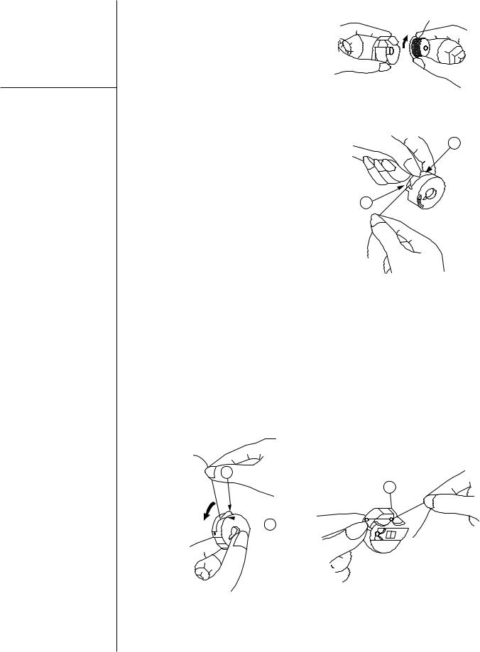
3.11
Bobbin Case Threading and Replacement
Note
When straight stitching, a better result can be obtained if bobbin thread is not threaded through bobbin case thread guide ‘3’ of Figure 17.
Hold bobbin case so that bobbin rotates in the direction of the arrow, and put bobbin in the bobbin case. (Figure 14)
Figure 14
Put thread into notch ’1’, and pull it
1
under tension spring ‘2’ (Figure 15)
2
Figure 15
Pull thread out from slot ‘2’ on end of spring ‘1’, and pass it through bobbin case thread guide ‘3’.
Leave thread approximately 4 inches longer from in the bobbin case. (Figure 16 and 17)
1
3
 2
2
Figure 16 |
Figure 17 |
Zigzag Sewing Machine | Instruction Manual and Parts List |
14 |
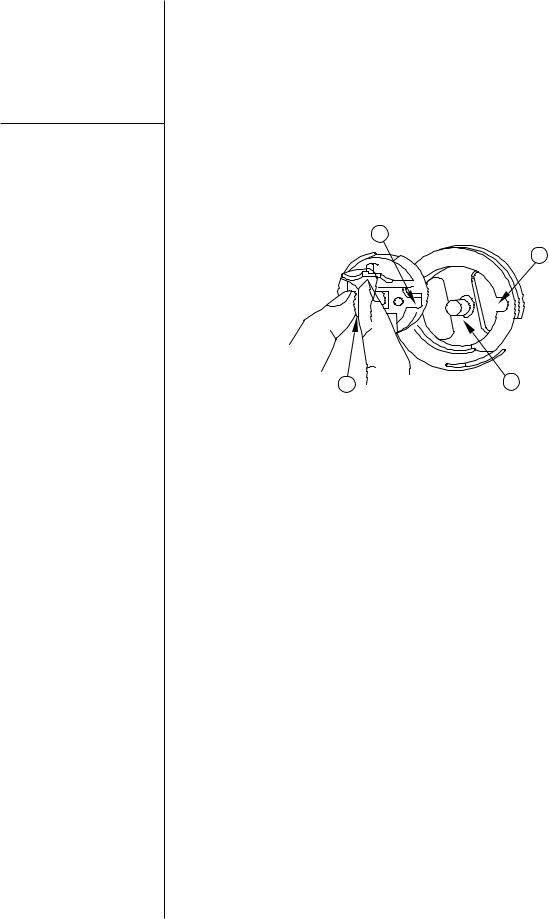
3.11
Bobbin Case Threading and Replacement
Caution
Switch off the machine.
Do not run machine without closing bed side. Danger of injury!
Hold bobbin case by latch ‘1’ and place it on spindle of bobbin case holder ‘2’ so that position finger ‘3’ enters notch ‘4’ at right of bobbin case holder (see Figure 18).
Release latch and press bobbin case firmly in place to assure proper position. Close bed slide.
3
4
1 |
2 |
Figure 18
Zigzag Sewing Machine | Instruction Manual and Parts List |
15 |
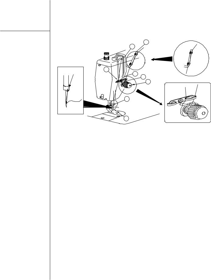
3.12
Machine Threading
Caution
Switch off the machine.
Do not operate the machine without thread take-up guard.
Do not operate the machine without finger guard.
When threading the machine head, |
Threading the machine in the order |
the needle bar should be at the |
shown in the Figure 19. |
highest point of its stroke. |
Leave thread approximately 4 cm |
|
|
|
longer in the needle. |
|
1 |
|
5 |
6
2  4
4
3
7
8
Figure 19
Zigzag Sewing Machine | Instruction Manual and Parts List |
16 |
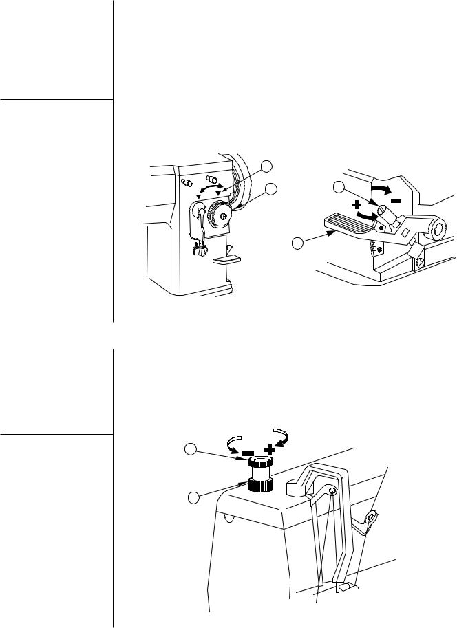
3.13
Stitch Length Adjustment (Except 20E-910)
Adjusting the stitch length:
Turn stitch length dial ‘1’ in the direction of the arrow, and align the desire number to marker dot ‘A’ on the machine (Figure 20).
The indication of the stitch length dial ‘1’ is in millimeters.
A
1
2
Adjusting the reverse stitch length:
Push feed reverse lever ‘2’ down for reverse feed, and release it for forward feed.
To adjust the reverse stitch length turn thumb screw '3' in direction of the marker ‘+’or‘-' as requested for the stitch length.
‘+’ direction:To lengthen
‘-‘ direction:To shorten
3
Figure 20
3.14
Presser Foot Pressure Adjustment
Loosen the nut ‘2’ and turn the presser spring regulator ‘1’ clockwise (in direction of the marker ‘+’), the pressure of the presser foot will be increased.
1
2
Turn the regulator ‘1’ counter clockwise (in direction of the marker ‘-‘ ), the pressure of the presser foot will be decreased.
Tighten the nut ‘2’.
Figure 21
Zigzag Sewing Machine | Instruction Manual and Parts List |
17 |
 Loading...