


4
Overlock Sewing Machine SON 90 A1
KOMPERNASS GMBH
BURGSTRASSE 21 · D-44867 BOCHUM
www.kompernass.com
ID-Nr.: SON 90 A1-01/11-V1
IAN: 64780
Overlock Sewing Machine
Operating instructions
Overlock varrógép
Használati utasítás
Šicí stroj Overlock
Návod k obsluze
Maszyna do szycia ze
ściegiem owerlok
Instrukcja obsługi
Opletilni (overlock)
šivalni stroj
Navodila za uporabo
Obnitkovací šijací stroj
Návod na obsluhu
SON 90 A1
i
1
uztr
2
3
o
p
a
s
d
e
w
q
4
f
5
6
7
8
9
0

INDEX PAGE
Intended Usage 3
Safety instructions 3
Items supplied 4
Technical Data 4
Description of the appliance 5
Bringing the upper blade into a rest position 5
Needle Information 5
Upper looper element 5
Opening the front flap 6
Preparation 6
Connecting the foot pedal . . . . . . . . . . . . . . . . . . . . . . . . . . . . . . . . . . . . . . . . . . . . . . . . . . . . . . . . . . . . . . . . . . . . . . . . . . . . . . . . . . . . . . .6
Controlling the sewing speed . . . . . . . . . . . . . . . . . . . . . . . . . . . . . . . . . . . . . . . . . . . . . . . . . . . . . . . . . . . . . . . . . . . . . . . . . . . . . . . . . . . .6
Safety switch . . . . . . . . . . . . . . . . . . . . . . . . . . . . . . . . . . . . . . . . . . . . . . . . . . . . . . . . . . . . . . . . . . . . . . . . . . . . . . . . . . . . . . . . . . . . . . . . . .6
Fitting the waste container . . . . . . . . . . . . . . . . . . . . . . . . . . . . . . . . . . . . . . . . . . . . . . . . . . . . . . . . . . . . . . . . . . . . . . . . . . . . . . . . . . . . . . .6
Removing needle(s) . . . . . . . . . . . . . . . . . . . . . . . . . . . . . . . . . . . . . . . . . . . . . . . . . . . . . . . . . . . . . . . . . . . . . . . . . . . . . . . . . . . . . . . . . . . .7
Inserting needle(s) . . . . . . . . . . . . . . . . . . . . . . . . . . . . . . . . . . . . . . . . . . . . . . . . . . . . . . . . . . . . . . . . . . . . . . . . . . . . . . . . . . . . . . . . . . . . .7
Operating the handwheel . . . . . . . . . . . . . . . . . . . . . . . . . . . . . . . . . . . . . . . . . . . . . . . . . . . . . . . . . . . . . . . . . . . . . . . . . . . . . . . . . . . . . . .7
Adjusting the thread tree . . . . . . . . . . . . . . . . . . . . . . . . . . . . . . . . . . . . . . . . . . . . . . . . . . . . . . . . . . . . . . . . . . . . . . . . . . . . . . . . . . . . . . . .7
Threading 8
General instructions for threading . . . . . . . . . . . . . . . . . . . . . . . . . . . . . . . . . . . . . . . . . . . . . . . . . . . . . . . . . . . . . . . . . . . . . . . . . . . . . . . . .8
Threading the upper looper thread (red) . . . . . . . . . . . . . . . . . . . . . . . . . . . . . . . . . . . . . . . . . . . . . . . . . . . . . . . . . . . . . . . . . . . . . . . . . . .8
Threading the lower looper thread (yellow) . . . . . . . . . . . . . . . . . . . . . . . . . . . . . . . . . . . . . . . . . . . . . . . . . . . . . . . . . . . . . . . . . . . . . . . .10
Threading yarn for the right needle (green) . . . . . . . . . . . . . . . . . . . . . . . . . . . . . . . . . . . . . . . . . . . . . . . . . . . . . . . . . . . . . . . . . . . . . . . .11
Threading yarn for the left needle (blue) . . . . . . . . . . . . . . . . . . . . . . . . . . . . . . . . . . . . . . . . . . . . . . . . . . . . . . . . . . . . . . . . . . . . . . . . . .13
Trial run . . . . . . . . . . . . . . . . . . . . . . . . . . . . . . . . . . . . . . . . . . . . . . . . . . . . . . . . . . . . . . . . . . . . . . . . . . . . . . . . . . . . . . . . . . . . . . . . . . . .14
Changing threads (binding together) 15
Set the stitch length 15
Setting the seam width 15
... by using the right or left needle . . . . . . . . . . . . . . . . . . . . . . . . . . . . . . . . . . . . . . . . . . . . . . . . . . . . . . . . . . . . . . . . . . . . . . . . . . . . . . . .15
... by turning the seam width adjustment knob . . . . . . . . . . . . . . . . . . . . . . . . . . . . . . . . . . . . . . . . . . . . . . . . . . . . . . . . . . . . . . . . . . . . . .16
Setting the seam width adjustment knob . . . . . . . . . . . . . . . . . . . . . . . . . . . . . . . . . . . . . . . . . . . . . . . . . . . . . . . . . . . . . . . . . . . . . . . . . . .16
Adjust sewing foot pressure 16
Differential transport 17
Manner of operation . . . . . . . . . . . . . . . . . . . . . . . . . . . . . . . . . . . . . . . . . . . . . . . . . . . . . . . . . . . . . . . . . . . . . . . . . . . . . . . . . . . . . . . . . .17
Gathered overlock seam - Settings . . . . . . . . . . . . . . . . . . . . . . . . . . . . . . . . . . . . . . . . . . . . . . . . . . . . . . . . . . . . . . . . . . . . . . . . . . . . . . .17
Stretched overlock seam - Settings . . . . . . . . . . . . . . . . . . . . . . . . . . . . . . . . . . . . . . . . . . . . . . . . . . . . . . . . . . . . . . . . . . . . . . . . . . . . . . .17
Free arm sewing 18
Read these operating instructions carefully before using the appliance for the first time and preserve this booklet for later reference. Pass this booklet on to
whoever might acquire the appliance at a future date.
- 1 -

Overlock seams 19
Roll hemmings . . . . . . . . . . . . . . . . . . . . . . . . . . . . . . . . . . . . . . . . . . . . . . . . . . . . . . . . . . . . . . . . . . . . . . . . . . . . . . . . . . . . . . . . . . . . . . .19
Binding-off and sample sewing . . . . . . . . . . . . . . . . . . . . . . . . . . . . . . . . . . . . . . . . . . . . . . . . . . . . . . . . . . . . . . . . . . . . . . . . . . . . . . . . . .20
Recommended tension settings . . . . . . . . . . . . . . . . . . . . . . . . . . . . . . . . . . . . . . . . . . . . . . . . . . . . . . . . . . . . . . . . . . . . . . . . . . . . . . . . . .20
2-thread overcast chain stitch (overlock) . . . . . . . . . . . . . . . . . . . . . . . . . . . . . . . . . . . . . . . . . . . . . . . . . . . . . . . . . . . . . . . . . . . . . . . . . . .21
2-thread-overcast-stitch . . . . . . . . . . . . . . . . . . . . . . . . . . . . . . . . . . . . . . . . . . . . . . . . . . . . . . . . . . . . . . . . . . . . . . . . . . . . . . . . . . . . . . . . .22
3-thread chain stitch (overlock) . . . . . . . . . . . . . . . . . . . . . . . . . . . . . . . . . . . . . . . . . . . . . . . . . . . . . . . . . . . . . . . . . . . . . . . . . . . . . . . . . .23
3-thread - flatlock seam . . . . . . . . . . . . . . . . . . . . . . . . . . . . . . . . . . . . . . . . . . . . . . . . . . . . . . . . . . . . . . . . . . . . . . . . . . . . . . . . . . . . . . . .24
3-thread overcast chain stitch (overlock) . . . . . . . . . . . . . . . . . . . . . . . . . . . . . . . . . . . . . . . . . . . . . . . . . . . . . . . . . . . . . . . . . . . . . . . . . . .25
3-thread safety stitch, highly elastic, imitated . . . . . . . . . . . . . . . . . . . . . . . . . . . . . . . . . . . . . . . . . . . . . . . . . . . . . . . . . . . . . . . . . . . . . . .26
4-thread safety stitch, highly elastic, imitated . . . . . . . . . . . . . . . . . . . . . . . . . . . . . . . . . . . . . . . . . . . . . . . . . . . . . . . . . . . . . . . . . . . . . . .27
Roll hemmings 28
3-thread rolled hem . . . . . . . . . . . . . . . . . . . . . . . . . . . . . . . . . . . . . . . . . . . . . . . . . . . . . . . . . . . . . . . . . . . . . . . . . . . . . . . . . . . . . . . . . . .28
3-thread upper looper overcast rolled hem . . . . . . . . . . . . . . . . . . . . . . . . . . . . . . . . . . . . . . . . . . . . . . . . . . . . . . . . . . . . . . . . . . . . . . . .28
2-thread rolled hem . . . . . . . . . . . . . . . . . . . . . . . . . . . . . . . . . . . . . . . . . . . . . . . . . . . . . . . . . . . . . . . . . . . . . . . . . . . . . . . . . . . . . . . . . . .29
2-thread lower looper overcast rolled hem . . . . . . . . . . . . . . . . . . . . . . . . . . . . . . . . . . . . . . . . . . . . . . . . . . . . . . . . . . . . . . . . . . . . . . . . .29
Flatlock decorative seams 30
Flatlock seam as assembly seam . . . . . . . . . . . . . . . . . . . . . . . . . . . . . . . . . . . . . . . . . . . . . . . . . . . . . . . . . . . . . . . . . . . . . . . . . . . . . . . . .30
Flatlock seam as decorative seam . . . . . . . . . . . . . . . . . . . . . . . . . . . . . . . . . . . . . . . . . . . . . . . . . . . . . . . . . . . . . . . . . . . . . . . . . . . . . . . .31
Overlock blind hems 31
Pin tucks 31
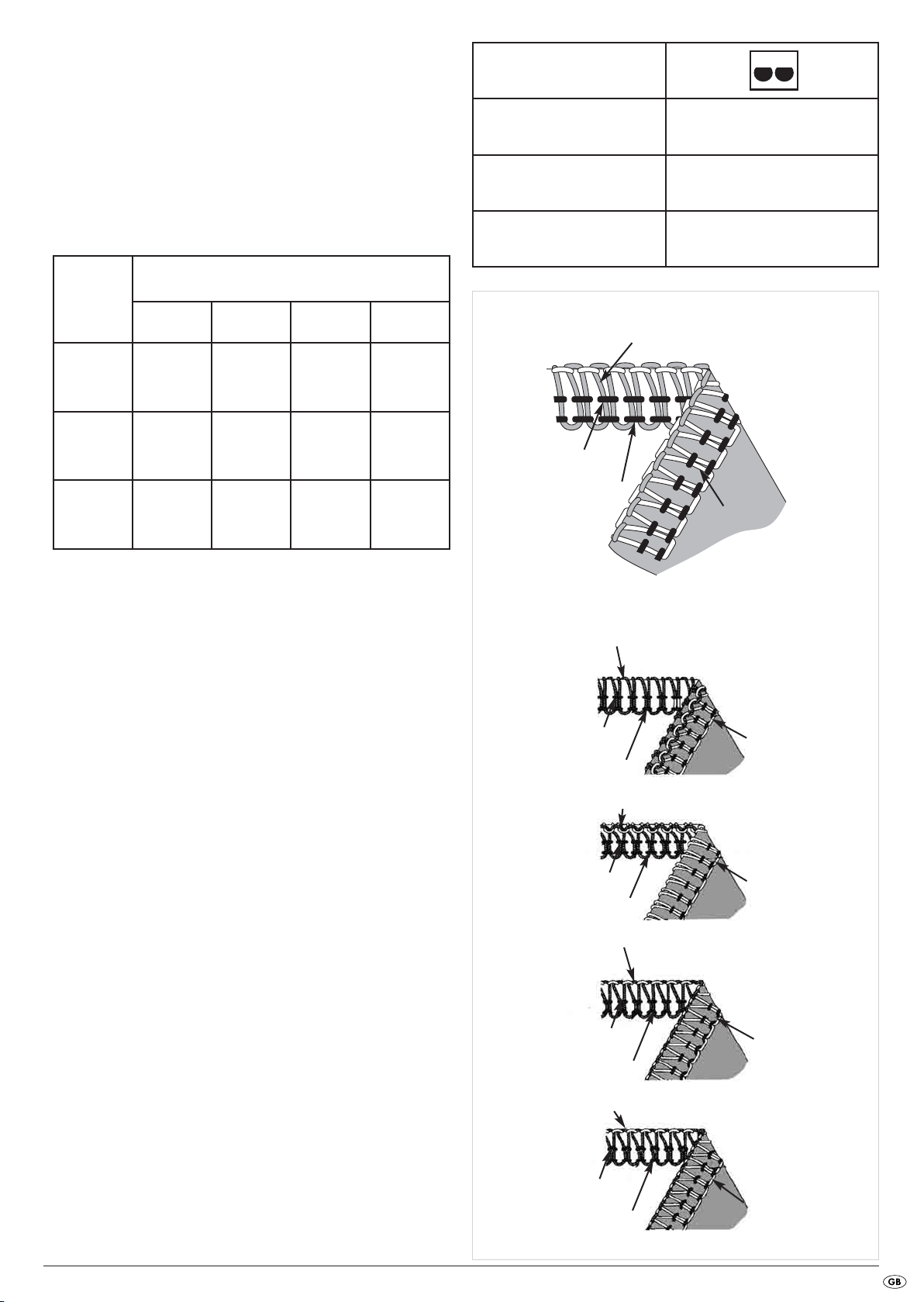
Sewing corners 32
Outer corners . . . . . . . . . . . . . . . . . . . . . . . . . . . . . . . . . . . . . . . . . . . . . . . . . . . . . . . . . . . . . . . . . . . . . . . . . . . . . . . . . . . . . . . . . . . . . . . .32
Inner corners . . . . . . . . . . . . . . . . . . . . . . . . . . . . . . . . . . . . . . . . . . . . . . . . . . . . . . . . . . . . . . . . . . . . . . . . . . . . . . . . . . . . . . . . . . . . . . . .32
Tips and Tricks 33
Using pins . . . . . . . . . . . . . . . . . . . . . . . . . . . . . . . . . . . . . . . . . . . . . . . . . . . . . . . . . . . . . . . . . . . . . . . . . . . . . . . . . . . . . . . . . . . . . . . . . . .33
Secure empty threads . . . . . . . . . . . . . . . . . . . . . . . . . . . . . . . . . . . . . . . . . . . . . . . . . . . . . . . . . . . . . . . . . . . . . . . . . . . . . . . . . . . . . . . . .33
Seam reinforcement . . . . . . . . . . . . . . . . . . . . . . . . . . . . . . . . . . . . . . . . . . . . . . . . . . . . . . . . . . . . . . . . . . . . . . . . . . . . . . . . . . . . . . . . . . .33
Edging . . . . . . . . . . . . . . . . . . . . . . . . . . . . . . . . . . . . . . . . . . . . . . . . . . . . . . . . . . . . . . . . . . . . . . . . . . . . . . . . . . . . . . . . . . . . . . . . . . . . .33
Maintenance and Cleaning 34
Cleaning and lubrication . . . . . . . . . . . . . . . . . . . . . . . . . . . . . . . . . . . . . . . . . . . . . . . . . . . . . . . . . . . . . . . . . . . . . . . . . . . . . . . . . . . . . . .34
Exchanging the lower blade . . . . . . . . . . . . . . . . . . . . . . . . . . . . . . . . . . . . . . . . . . . . . . . . . . . . . . . . . . . . . . . . . . . . . . . . . . . . . . . . . . . .34
Storage 35
Disposal 35
Warranty and Service 35
Importer 35
Troubleshooting 36
- 2 -

Intended Usage
OVERLOCK SEWING MACHINE
This overlock sewing machine is intended ...
– for use as a portable machine,
– for the trimming of material edges (sewing) of typical household
textiles, and ...
– only for domestic household use.
Safety instructions
Like any other electrical device, a sewing machine can cause serious, even
life-threatening injuries. To avoid these, and to work safely:
• Always disconnect the power supply when leaving the machine unattended.
This will prevent the risk of accidents if the machine is switched on
accidentally.
• Always first disconnect the power plug before carrying out maintenance
work on the machine. This will prevent possibly life-threatening electric
shocks. The LED light is not exchangeable.
• Do not pull the plug out of the wall socket by the lead. When pulling
out the plug, always hold the plug, not the lead.
• Only use the sewing machine in dry rooms.
• Arrange for defective power plugs and/or cables to be replaced at
once by qualified technicians or our Customer Service Department.
• This appliance is not intended for use by individuals (including children) with
restricted physical, physiological or intellectual abilities or deficiences in
experience and/or knowledge unless they are supervised by a person
responsible for their safety or receive from this person instruction in how
the appliance is to be used.
• Children should be supervised to ensure that they do not play with
the appliance.
• Never use the machine when the ventilation apertures are blocked.
Keep the ventilation apertures of the machine and the foot switch free
from fluff, dust and waste material.
• Should the cable connected to the foot pedal become damaged,
to avoid potential risks it must be replaced by the manufacturer, his
customers services or a similarly qualified person.
This overlock sewing machine is not intended ...
– to be installed at a permanent location,
– for the processing of other materials (e.g. leather, canvas, sailcloth
and other heavy materials),
– for commercial or industrial use.
Warning about injuries and material damages:
• Keep your work space tidy. An untidy workplace can lead to accidents.
• Provide adequate lighting when working!
• Do not wear loose clothing or jewellery, as these can be caught in
moving parts. You should also wear a hair net if you have long hair.
• Avoid adopting an unusual posture. Remain steady and in a well-balanced
position at all times.
• If accidents occur as a result of handling the machine with insufficient
care, or failure to follow the safety instructions in this manual, then the
manufacturer cannot accept liability.
• Never cover the ventilation slots! Risk of overheating!
• Keep the sewing machine oil well away from children.
• If swallowed, or should eye contact be made with the sewing machine
oil, consult a doctor immediately.
- 3 -
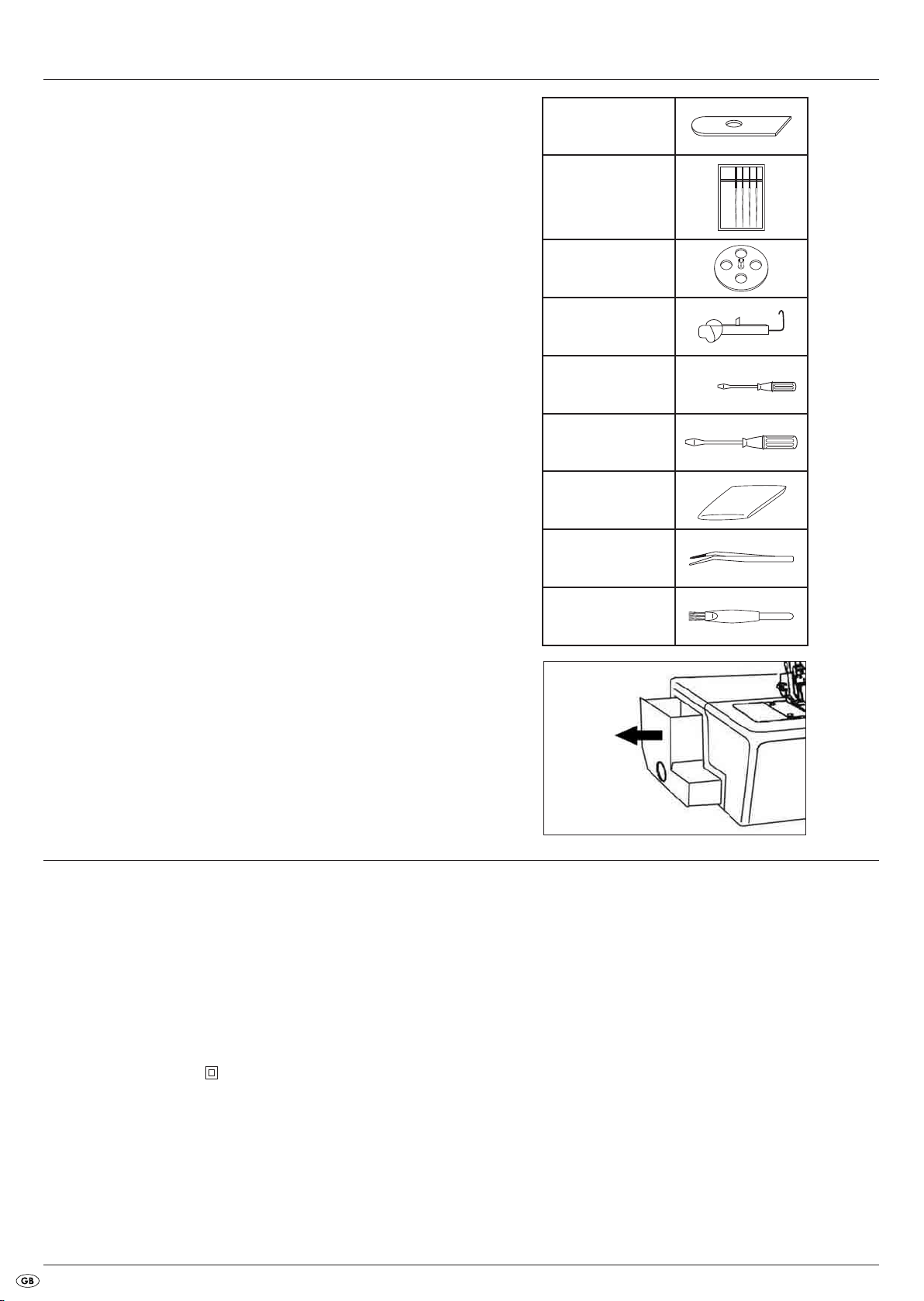
Items supplied
Overlock Sewing Machine
Oil
Waste container
Accessory box
Operating instructions
Replacement blade
(bottom)
2 Needles Nr. 11
4 Needles Nr. 14
(2 in the machine,
pre-installed)
4 Bobbin caps
Upper looper element
Screwdriver small
Screwdriver large
Covering hood
The accessories are to be found in the accessory box on the side
of the machine (Fig.1.).
Technical Data
Number of threads 2, 3 or 4
Number of needles 2 or 1
Sewing speed approx. 1200 rpm
Stitch width
right: 3.0 mm - 4.5 mm
left: 5.2 mm - 6.7 mm
Stitch length 1 – 4 mm
Needles HA x 1 Nr. 11-14 or 130/705 Nr. 75-90
Power consumption : 90 W
Rated voltage: 220 - 240 V ~, 50Hz
Protection class: II
Tweezers
Brush with integrated
unstitcher
Fig. 1
The sound intensity level under normal operating conditions amounts to
78dB(A).
Foot pedal
Use only the foot pedal originally supplied with this sewing machine:
- ELECTRONIC FDM Speed Controller
- Type KD - 2902
- 4 -
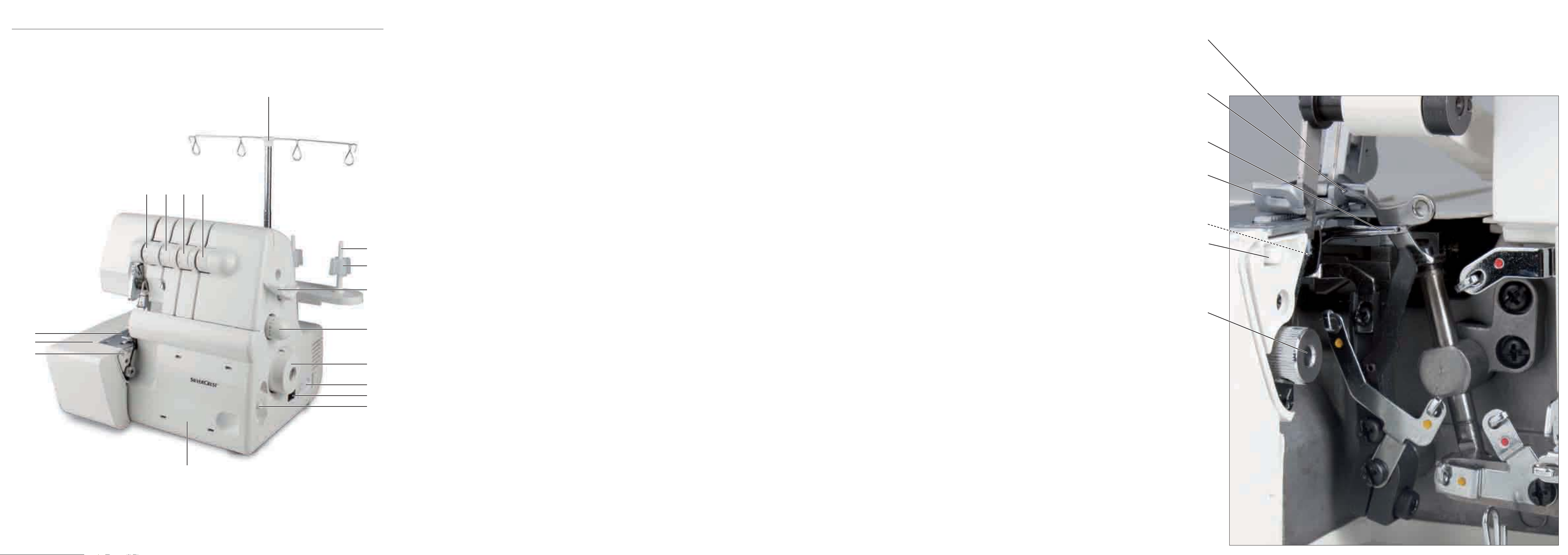
Description of the appliance
On the front fold-out page:
1 Thread tree
2 Spool support
3 Thread roll centerer
4 Sewing foot lever
5 Adjustment wheel for stitch length
6 Handwheel
7 Connection Footpedal/Power supply
8 Power switch (On/Off switch)
9 Differential transport lever
0 Front flap
q Support plate of the seam width finger
w Free arm
e Stitch plate
r Thread tension selector (left needle)
t Thread tension selector (right needle)
z Thread tension selector (upper looper)
u Thread tension selector (lower looper)
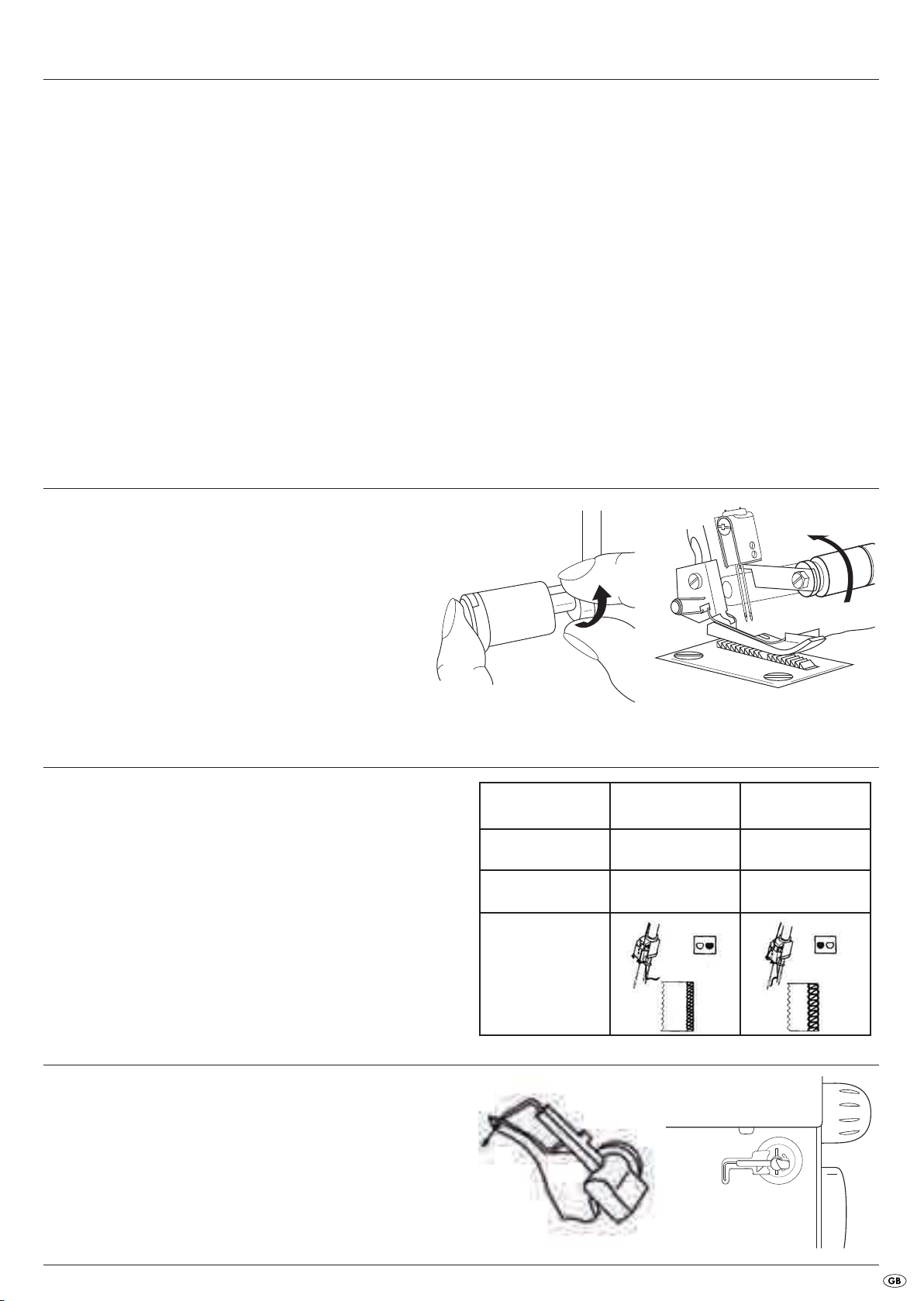
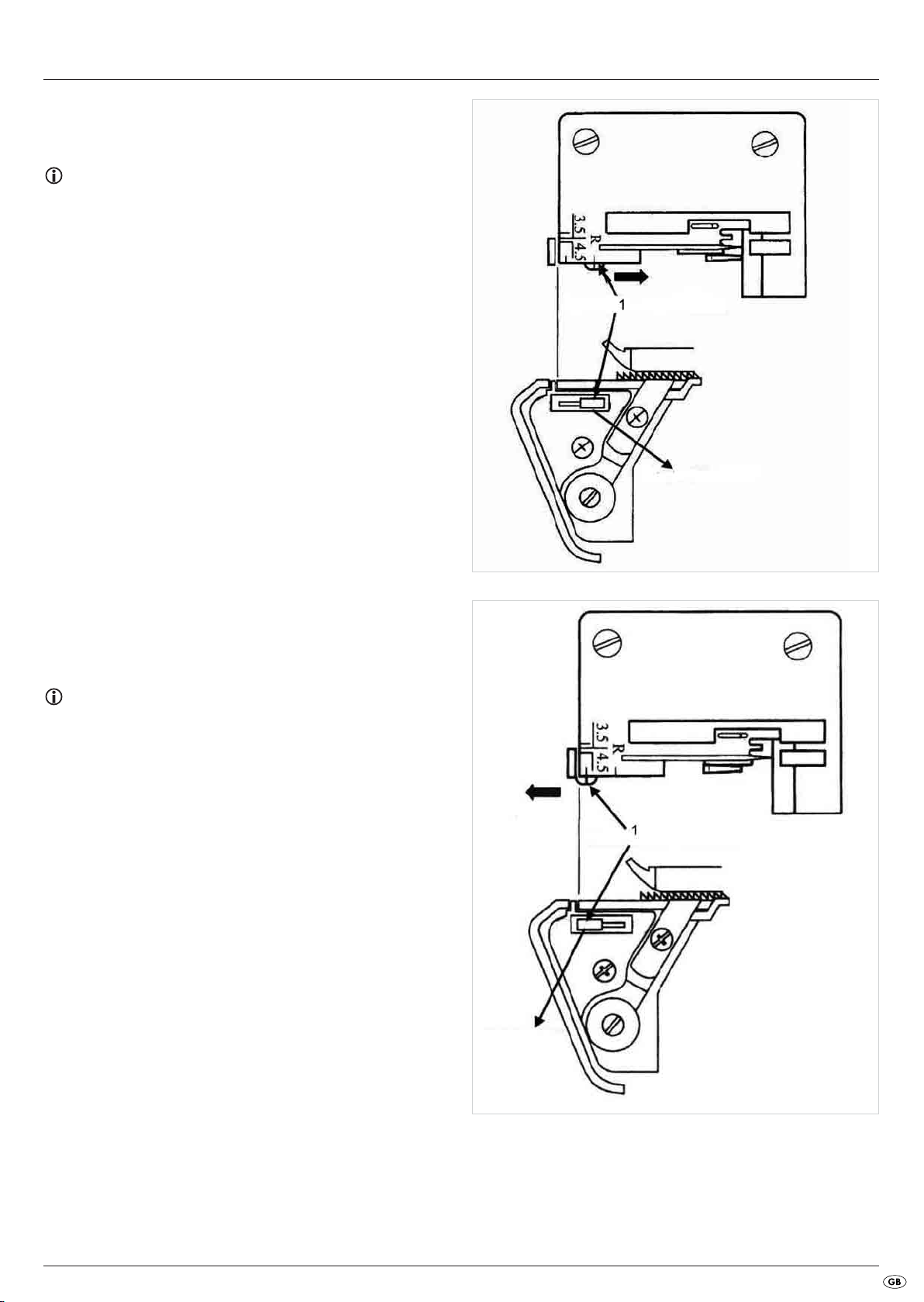
Bringing the upper blade into a rest position
To make certain types of seam, or to more easily operate the adjustment wheel for cutting width f, you must bring the upper blade i into
a rest position.
For this, press the upper blade i to the right and rotate it a little, so
that it is firmly seated (Fig. 2 and 3).
On the rear fold-out page:
i movable upper blade (Upper blade)
o Upper looper
p Lower looper
a Sewing foot
s Fixed lower blade
d Seam width switch
f Seam width adjustment knob
Fig. 2
Needle Information
This machine uses standard commercial flat-shaft needles for sewing machines.
These prevent the incorrect insertion of the needle. You can purchase these
needles in any specialist shop.
You can use needles of the sizes 11 and 14 in this machine.
The adjoining table gives you a brief overview of the differences when using a
needle (for detailed information, see "Setting the seam width).
Upper looper element
For some kinds of stitches you will need to use the upper looper element.
When you need to insert it is described in the individual stitches.
Insert the small wire from behind in the eyelet of the upper looper o and
the plastic bolt, on the other end and from the front, in the hole in the upper
looper o (Fig. 4a).
You can store the upper looper ready for use in the slot behind the front
flap 0 (Fig. 4b).
Fig. 3
Seam width 3.5 mm 5.7 mm
Employed needle right needle left needle
Thread tension selector green blue
- 5 -
Fig.4a
Fig.4b
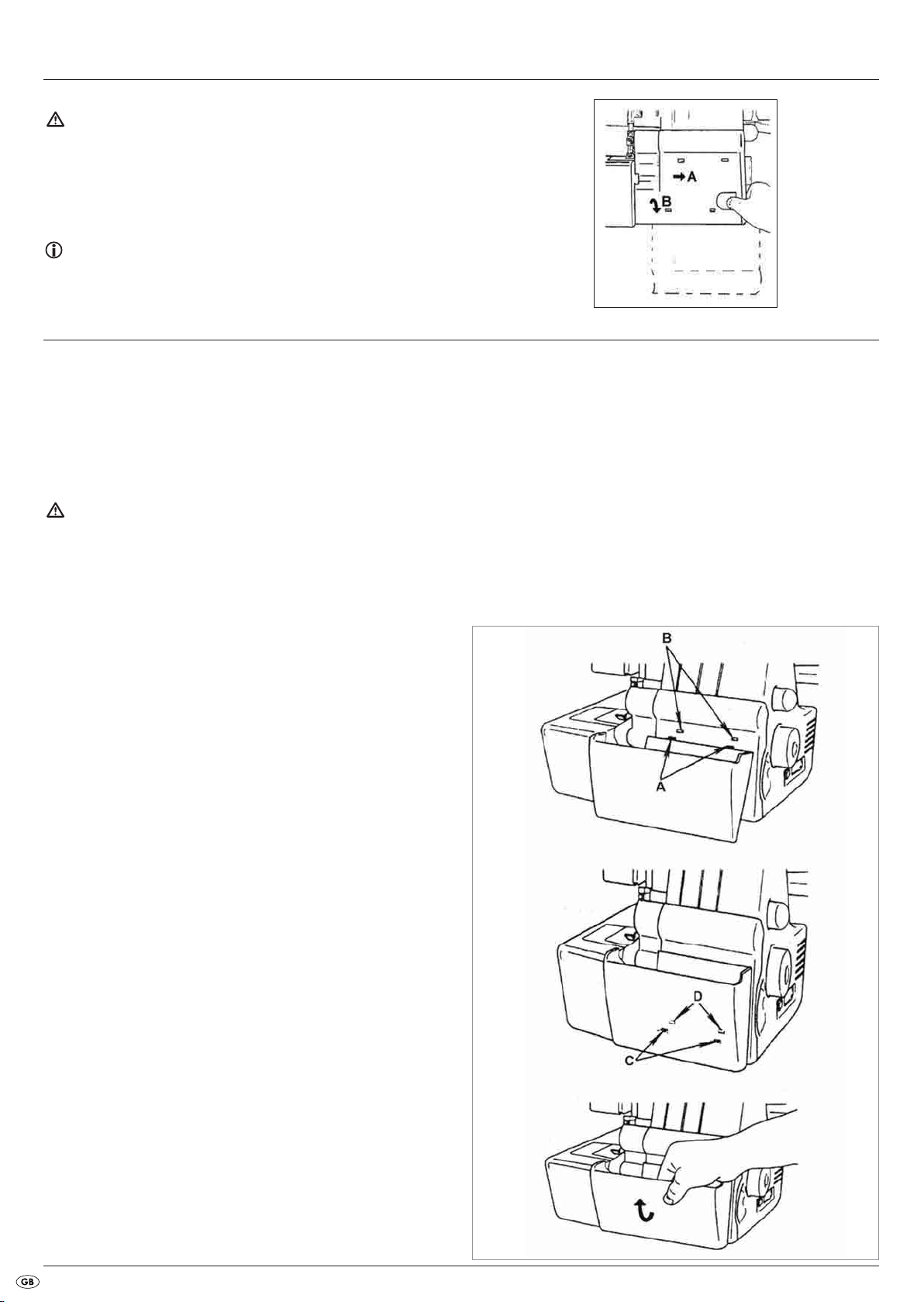
Opening the front flap
Attention!
Always switch the machine off with the power switch 8 when you open
the front flap 0. Risk of Injury!
• Slide the front flap 0 to the right (A) and then pull it towards you (B)
(Fig. 5).You will see the upper looper behind the front flap 0.
Note:
While sewing, the front flap 0 must be kept closed!
Preparation
Place the overlock sewing machine on a stable and level surface.
Ensure there is sufficient illumination at your workplace.
Connecting the foot pedal
• Insert the plug of the foot pedal into the socket for the foot pedal 7.
• Insert the plug into a power socket.
To switch the machine on, press the power switch 8.
Attention!
During absences from the machine or when doing maintenance work,
always remove the plug from the mains power socket. Risk of Injury!
Fig. 5
Controlling the sewing speed
The sewing speed is controlled by means of the footpedal. The sewing
speed is changed by applying more or less pressure to the footpedal.
Safety switch
This machine is fitted with a micro safety switch. You cannot start the machine
if the front flap 0 is open. Close the front flap 0 before you start to sew.
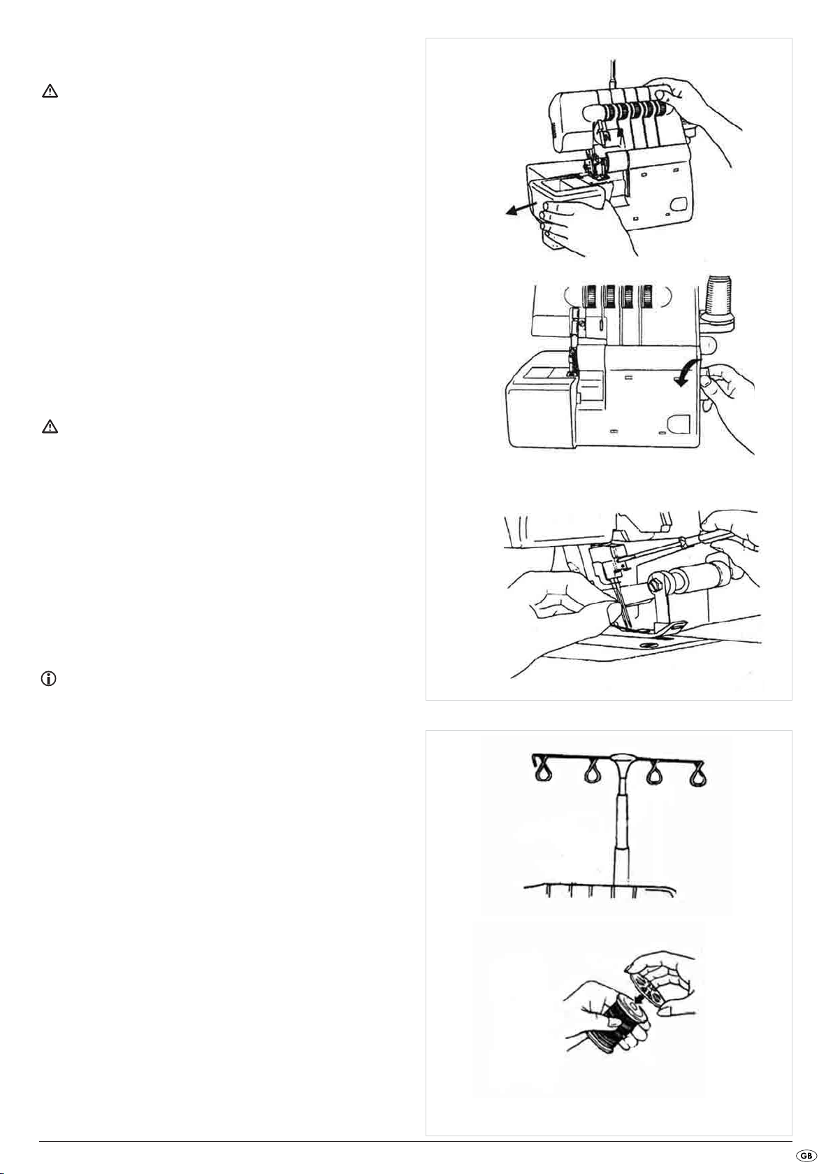
Fitting the waste container
The waste container collects remnants during sewing, so that your workplace
stays tidy.
• First push the two restraints (A) into the receiving holes (B) (Fig. 6).
• Then guide the two restraints (C) into the receiving holes (D) (Fig. 7).
• To remove the waste container, pull it forward and then tilt it slightly
(Fig. 8).
Fig. 6
Fig. 7
- 6 -
Fig. 8
Removing needle(s)
Tip!
Attention!
Before exchanging the needles, remove the power plug. This prevents an
unintended starting of the machine. If you do not, you run a risk of serious
injury!
T
An exchange of the needles is easier if you first remove the free arm cover
(Fig. 9a)!
1. Turn the handwheel 6 towards yourself until the needles are in the
highest position (Fig. 9b)
2. Loosen the needle retaining screws with the small screwdriver until the
needles are free (Fig. 10).
3. Remove the needles.
Inserting needle(s)
Attention!
Before exchanging the needles, remove the power plug. This prevents an
unintended starting of the machine. If you do not, you run a risk of serious
injury!
1. Hold the needle with the flattened side to the rear.
2. Push the needle as far as it will go into the needle holder.
3. Firmly tighten the needle screws with the small screwdriver (Fig. 10).
Operating the handwheel
Note:
Always turn the handwheel 6 only towards yourself (Fig. 9b).
Fig.9a
Fig.9b
Fig.10
Adjusting the thread tree
• Completely remove the thread tree 1 before threading (Fig. 11).
• Turn the thread tree 1 so that the thread guides stand exactly above
the spool supports 2.
• In the correct position, the two jointed parts of the thread tree 1 snap
audibly into position.
• Place the thread rolls on the thread roll centrings.
If you do not use industrial coils, remove the thread roll centrings. Slide
a spool cap onto each of the thread rolls (Fig. 12). This will hold them in
place when sewing.
Fig. 11
Fig. 12
- 7 -
Threading
143 2
Note:
On delivery, all 4 threads are already threaded. You can begin sewing immediately. Should you wish to change the thread, and all 4 threads are still
threaded, then proceed as described in the chapter "Changing threads
(binding together)“.
Should you need to rethread all threads from scratch, then proceed as
described in this chapter, "Threading“.
General instructions for threading
Attention!
Before threading, ALWAYS place the power switch 8 at "O" (Off) and
remove the plug from the mains power socket. This prevents an unintended
starting of the machine. If you do not, you run a risk of serious injury!
Correct threading is important, so that the stitches are not irregular and that
the yarn does not break.
Behind the front flap 0 there is a diagram with instructions for threading.
Additionally, the thread guides are marked in various colours.
In the accessory box you will find tweezers, the use of which helps make
threading easier.
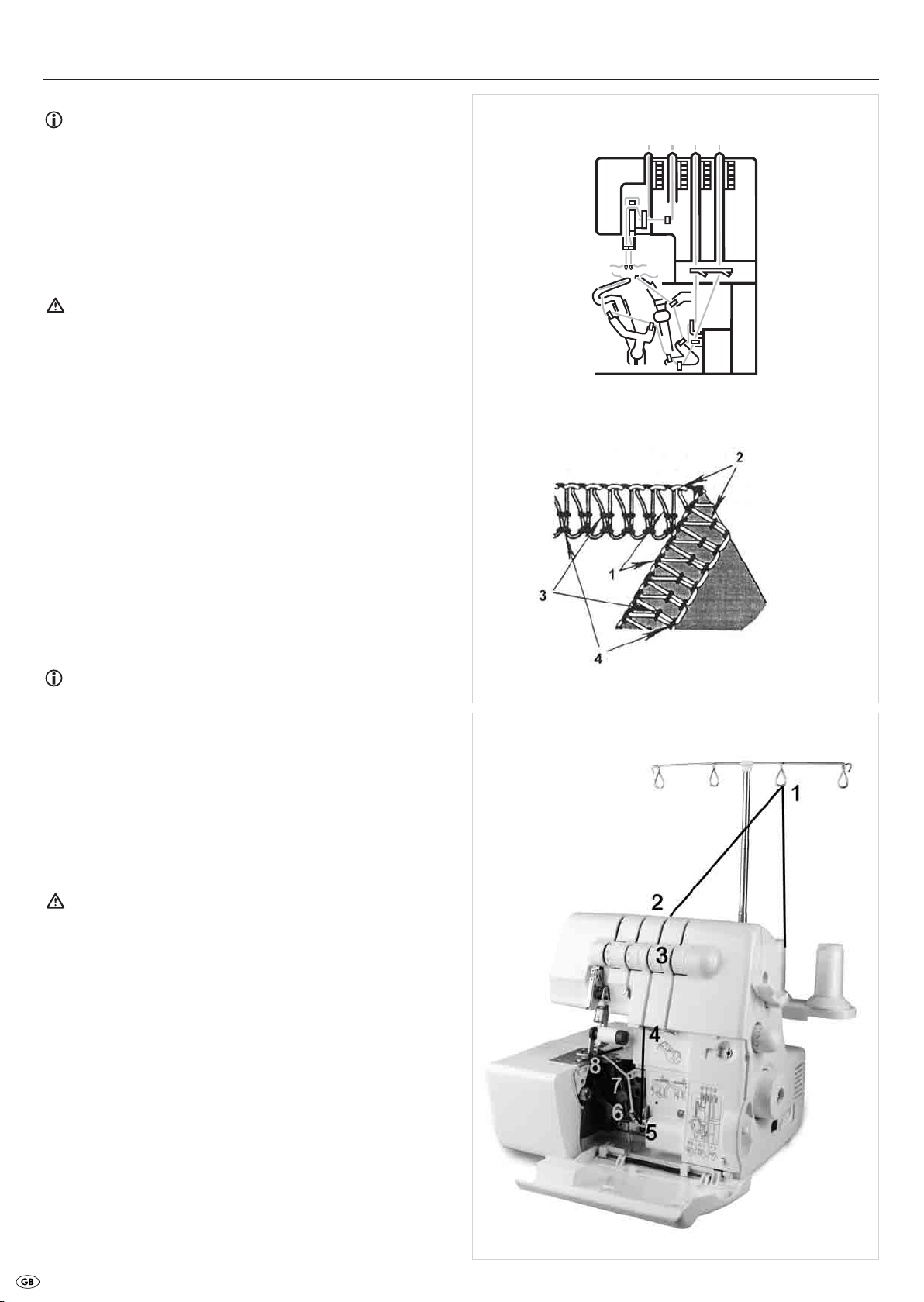
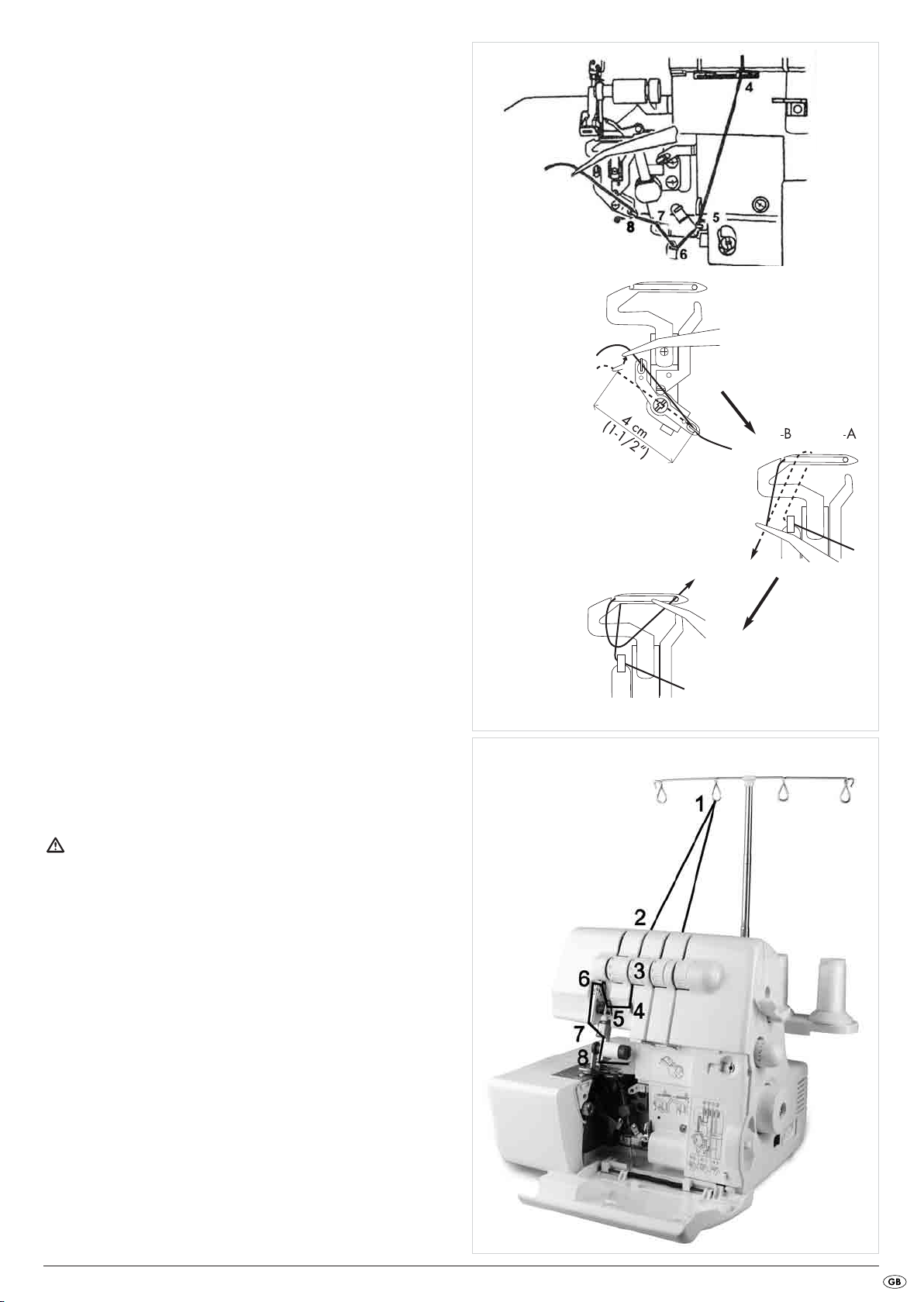
Threading is done in this order (Fig. 13/14):
1. First step: Upper looper (red)
2. Second step: Lower looper (yellow)
3. Third step: Thread for the right needle (green)
4. Fourth step: Thread for the left needle (blue)
Note:
When all threads are threaded, and the lower looper thread loosens itself,
proceed as follows:
• Unthread the two threads of the needles.
• Then thread the lower looper thread.
• First then rethread the threads of the two needles again.
The needles must always be the last to be threaded!
For simplification, the individual steps are numbered on the drawings.
Fig. 13
Fig. 14
Threading the upper looper thread (red)
Attention!
Before threading, ALWAYS place the power switch 8 at "O" (Off) and
remove the plug from the mains power socket. This prevents an unintended
starting of the machine. If you do not, you run a risk of serious injury!
Always use the accompanying drawings for assistance.
Figure 15 shows the thread path of the upper looper thread. The individual
threading positions are numbered and described in detail in the following.
1. Open the front flap 0.
2. Guide the yarn from back to front through the thread tree 1 (1).
Fig. 15
- 8 -
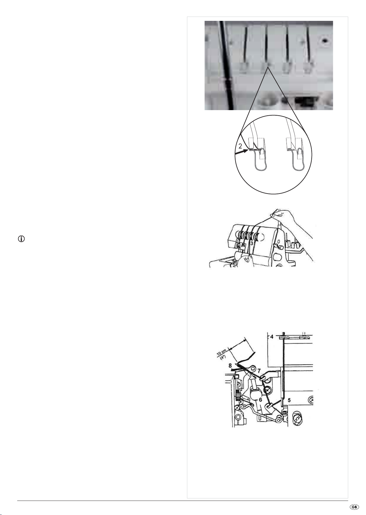
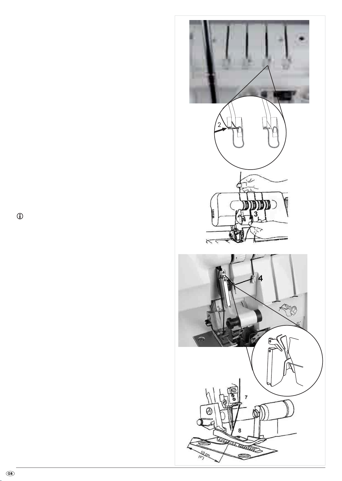
3. Thread the yarn into the thread guide in that you pull the thread down
until it slips under the thread guide (2) (Fig. 16).
Fig. 16
4. Firmly hold the yarn with your fingers, guide it between and through
the discs of the thread tension selector z and then pull it down (3)
(Fig. 17).
Note:
The yarn must lie correctly between the two discs of the thread tension
selector z.
5. Thread the yarn in the looper area as per the red markings (Fig. 18).
6. Pull the thread from back to front through the upper looper o.
7. Pull around 10 cm of thread through the looper and place it behind
the stitch plate e.
Fig. 17
- 9 -
Fig. 18
Threading the lower looper thread (yellow)
Attention!
Before threading, ALWAYS place the power switch 8 at "O" (Off) and
remove the plug from the mains power socket. This prevents an unintended
starting of the machine. If you do not, you run a risk of serious injury!
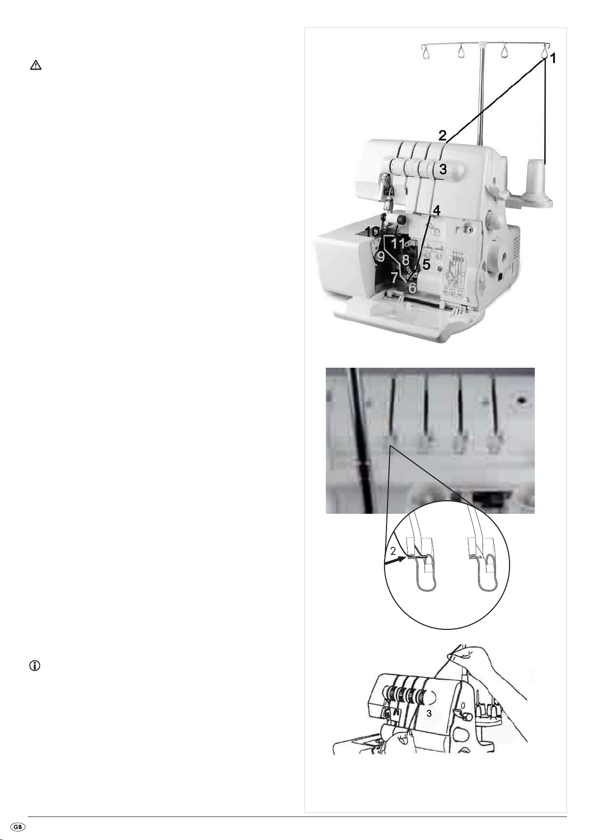
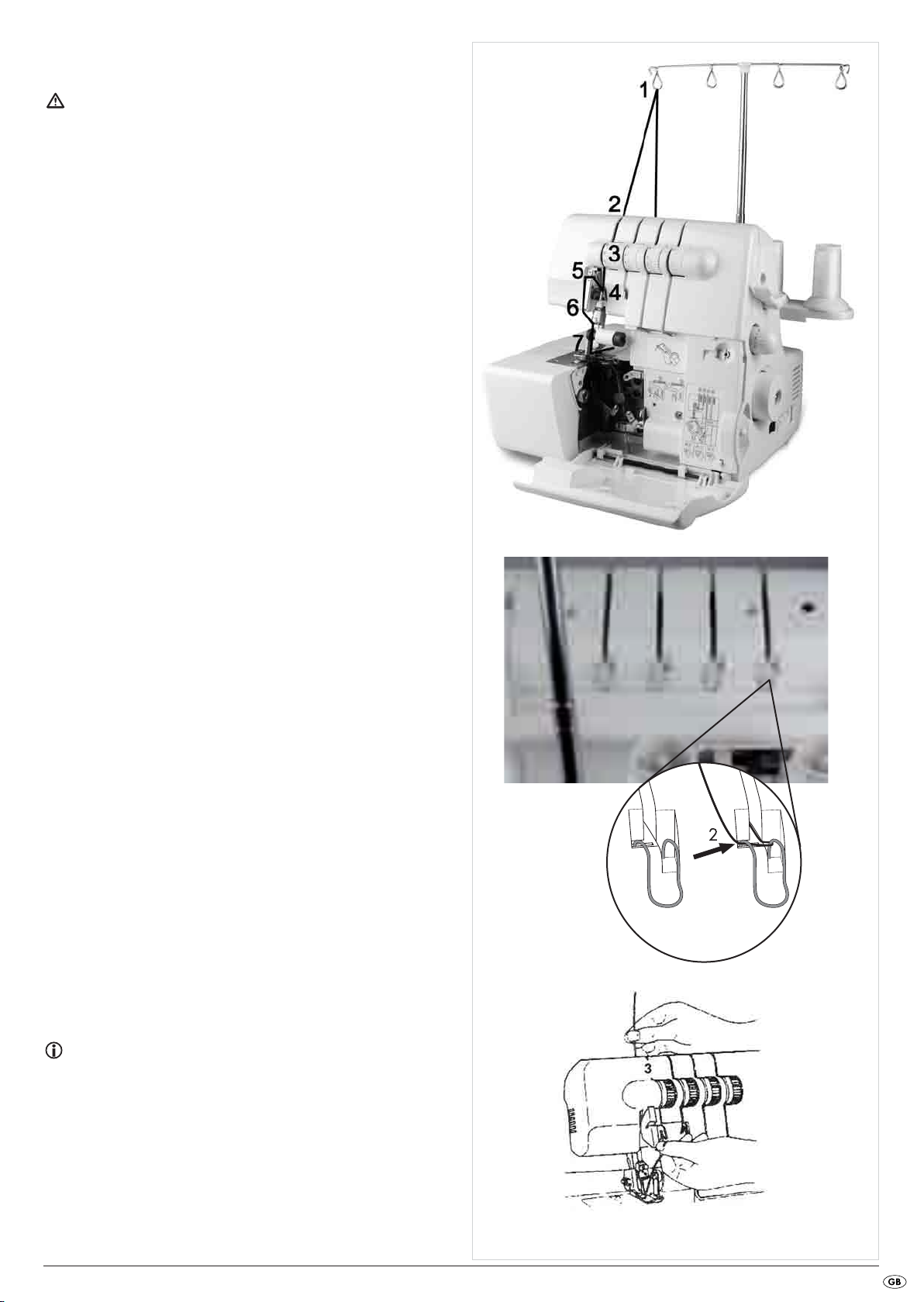
Figure 19 shows the thread path of the lower looper thread. The individual
threading positions are numbered and described in detail in the following.
1. Guide the yarn from back to front through the thread tree 1 (1).
2. Thread the yarn into the thread guide in that you pull the thread down
until it slips under the thread guide (2) (Fig. 20).
3. Firmly hold the yarn with your fingers, guide it between and through
the discs of the thread tension selector u and then pull it down (3)
(Fig. 21).
Fig. 19
Fig. 20
Note:
The yarn must lie correctly between the two discs of the thread tension
selector u.
4. Turn the handwheel 6 to yourself until the lower looper p is at the
far right.
Fig. 21
- 10 -
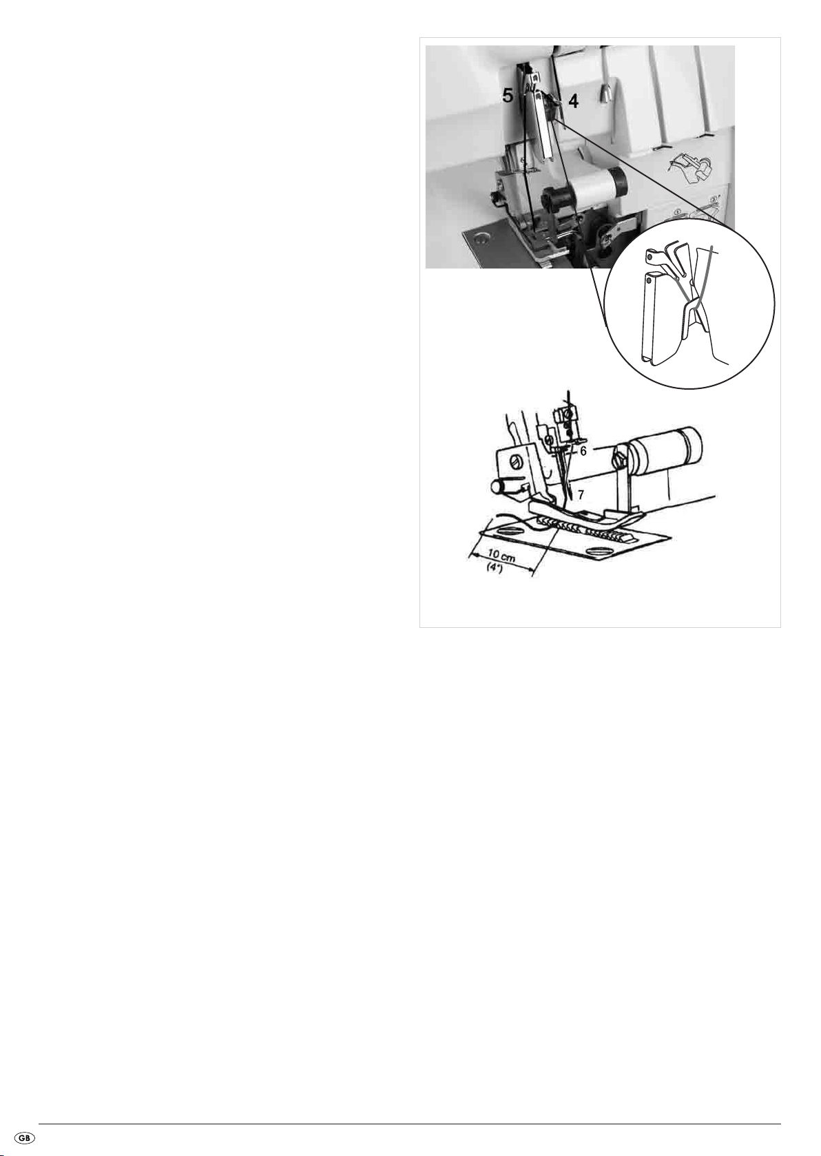
5. Thread the yarn in the looper area as per the yellow markings (4 - 8)
over
(Fig. 22).
6. Firmly hold the yarn with the tweezers about 4 cm from the thread
guide (Fig. 23).
7. Now guide it lightly, from the left and with the tweezers, under the
thread guide.
8. Pull the yarn upwards into the thread guide (9).
Fig. 22
9
9. Lead the yarn to the rear and over the upper end of the lower looper p
(10A) (Fig. 23).
10. Then, carefully pull the yarn down so that it slides into the recess of
the looper (10B) (Fig. 23). For this step also use the drawing which
is attached to the machine!
11. Guide the thread through the looper eyelet (11). The yarn should run
in the groove of the lower looper p (Fig. 23).
12. Draw around 10 cm of yarn through the looper and place it to the
rear
the upper looper o and the stitch plate e.
Threading yarn for the right needle (green)
Attention!
Before threading, ALWAYS place the power switch 8 at "O" (Off) and
remove the plug from the mains power socket. This prevents an unintended
starting of the machine. If you do not, you run a risk of serious injury!
Fig. 23
11
8
10
10
Figure 24 shows the thread path of the right needle thread. The individual
threading positions are numbered and described in detail in the following.
1. Guide the yarn from back to front through the thread tree 1 (1).
Fig. 24
- 11 -
2. Thread the yarn into the thread guide in that you pull the thread down
5
6
until it slips under the thread guide (2) (Fig. 25).
3. Firmly hold the yarn with your fingers, guide it between and through
the discs of the thread tension selector t and then pull it down (3)
(Fig. 26).
Fig. 25
Note:
The yarn must lie correctly between the two discs of the thread tension
selector t.
4. Thread the yarn as per the green markings (4- 7) (Fig. 27/28).
5. Thread the yarn through the right needle (8) (Fig. 28).
6. Lay the yarn to the rear under the sewing foot a.
Fig. 26
Fig. 27
Fig. 28
- 12 -
Threading yarn for the left needle (blue)
Attention!
Before threading, ALWAYS place the power switch 8 at "O" (Off) and
remove the plug from the mains power socket. This prevents an unintended
starting of the machine. If you do not, you run a risk of serious injury!
Figure 29 shows the thread path of the left needle thread. The individual
threading positions are numbered and described in detail in the following.
1. Guide the yarn from back to front through the thread tree 1 (1).
2. Thread the yarn into the thread guide in that you pull the thread down
until it slips under the thread guide (2) (Fig. 30).
Fig. 29
Fig. 30
3. Firmly hold the yarn with your fingers, guide it between and through
the discs of the thread tension selector r and then pull it down (3)
(Fig. 31).
Note:
The yarn must lie correctly between the two discs of the thread tension
selector r.
Fig. 31
- 13 -
4. Thread the yarn as per the blue markings (4 - 6) (Fig. 32/33).
4
5
5. Thread the yarn through the left needle (7) (Fig. 33).
6. Lay the yarn to the rear under the sewing foot a.
Fig. 32
Trial run
When yarn has been threaded for the first time, or after a yarn breakage
it must be rethreaded, proceed as follows:
Lift the sewing foot a.
Hold the ends of the threads between the fingertips of your left hand, slowly turn the handwheel 6 two or three times towards yourself and
then check the threads once again.
Lay the material for a trial run under the sewing foot a and slowly start
to sew.
The material will be automatically fed through.
When the task is complete, continue sewing until an approximately
5cm (2") long length of threads has formed at the end of the material.
Cut through the threads with scissors.
Fig. 33
- 14 -
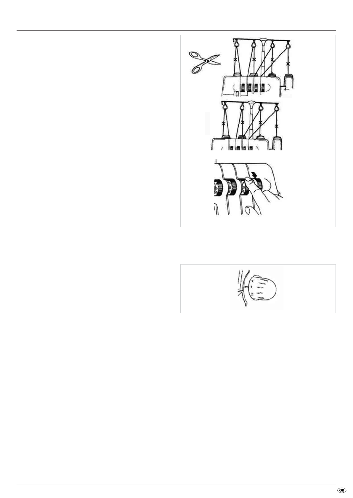
Changing threads (binding together)
Changing threads is quite simple with the following procedure:
1. Cut the yarn above the spool support 2 (Fig. 34) and place the new
roll of thread on the spool support 2.
2. Tie the ends of the new and the old thread together (Fig. 35).
3. Place the thread tension selector r/t/z/u at "0" (Fig. 36) and lift
the sewing foot a.
4. Pull on the other end of the yarn until the knot passes under the sewing
foot a.
5. For threading it in the needle, pull on the other end until the knot is in
the eye of the needle and then cut the yarn to the left and right of the
knot. Then carry out the rethreading.
Fig. 34
Fig. 35
Fig. 36
Set the stitch length
The stitch length can be adjusted from 1.0 to 4.0 mm. Almost all overlock
work is carried out with a stitch length of 2.5 – 3.5 mm.
Turn on the adjustment wheel for stitch length 5 (Fig. 37) to adjust the
stitch length:
• A stitch length of 3 mm is recommended for most sewing.
• For the working of heavy fabrics, a stitch length of 4 mm is to be recommended.
• For the working of light fabrics, a stitch length of 2 mm is to be recommended..
With these settings you will produce respectable seams and the fabric
will not be crimped.
Setting the seam width
The width of seams can be determined both by changing the needle position
and via the seam width adjustment knob f.
... by using the right or left needle
The width of the seam can be determined by using the left or the right
needle.
Fig. 37
• Only the left needle is used: 5.7 mm
• Only the right needle is used: 3.5 mm
- 15 -
... by turning the seam width adjustment knob
By using the seam width adjustment knob f, seam width can be adjusted
within the ranges indicated below.
• Only the left needle is used: 5.2 - 6.7 mm
• Only the right needle is used: 3.0 - 4.5 mm
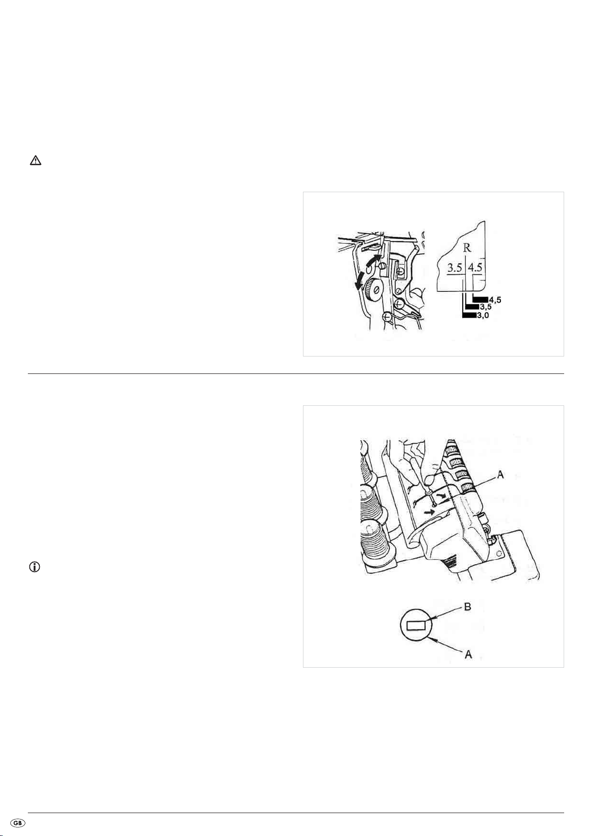
Setting the seam width adjustment knob
Attention!
Before making adjustments with the seam width adjustment knob f
always place the mains switch 8 at the position "O" (Off). This prevents
an accidental start of the appliance and thus the risk of injury!
• Open the front flap 0, this can make the adjustment easier to carry out.
• Turn the seam width adjustment knob f to the desired seam width
(Fig. 38). Orientate yourself on the scale on the stitch plate e
(Fig. 39).
Fig. 39
Fig. 38
Adjust sewing foot pressure
Upon delivery, the sewing foot pressure is set for medium-weight materials.
If you wish to use heavier or lighter materials, adjust the sewing foot pressure
as follows:
• For lighter fabrics, you need to reduce the pressure.
• For heavier fabrics, you need to increase the pressure.
Insert the small screwdriver into the hole on the upper side of the machine
(Fig. 40). The pressure adjustment screw is located here (A). Ensure that the
screwdriver slips into the slot of the pressure adjustment screw (B) (Fig. 41).
• Turn the screwdriver in the direction "+" if you want to increase the pressure.
• Turn the screwdriver in the direction "-" if you want to reduce the pressure.
Note:
To return to the factory-set default sewing foot pressure, turn the pressure
adjustment screw as far as it will go anti-clockwise (-). Then turn it 6 rotations in
a clockwise (+) direction.
The standard sewing foot pressure is reset.
Fig. 40
Fig. 41
- 16 -
Differential transport
Manner of operation
The machine has two sets of toothed rack feeders, one to the front and one
to the rear. Both sets move independant of each other. Through the differential
feed motion both toothed rack sets can move themselves at various speeds.
With this, the fabric is stretched or gathered, depending on which transport
differential has been set between the front and rear rack feeders.
With the aid of the differential transport, interesting effects can be achieved when sewing overlock seams on stretch materials and diagonally cut
fabrics (Fig. 43).
Note:
When the differential transport lever 9 stands at "1.0", that corresponds
to a differential transport ratio of 1:1. Both toothed feed racks move at the
same rate (Fig. 42).
The differential transport lever 9 can be adjusted in a range from 1:0.7
to 1:2.0.
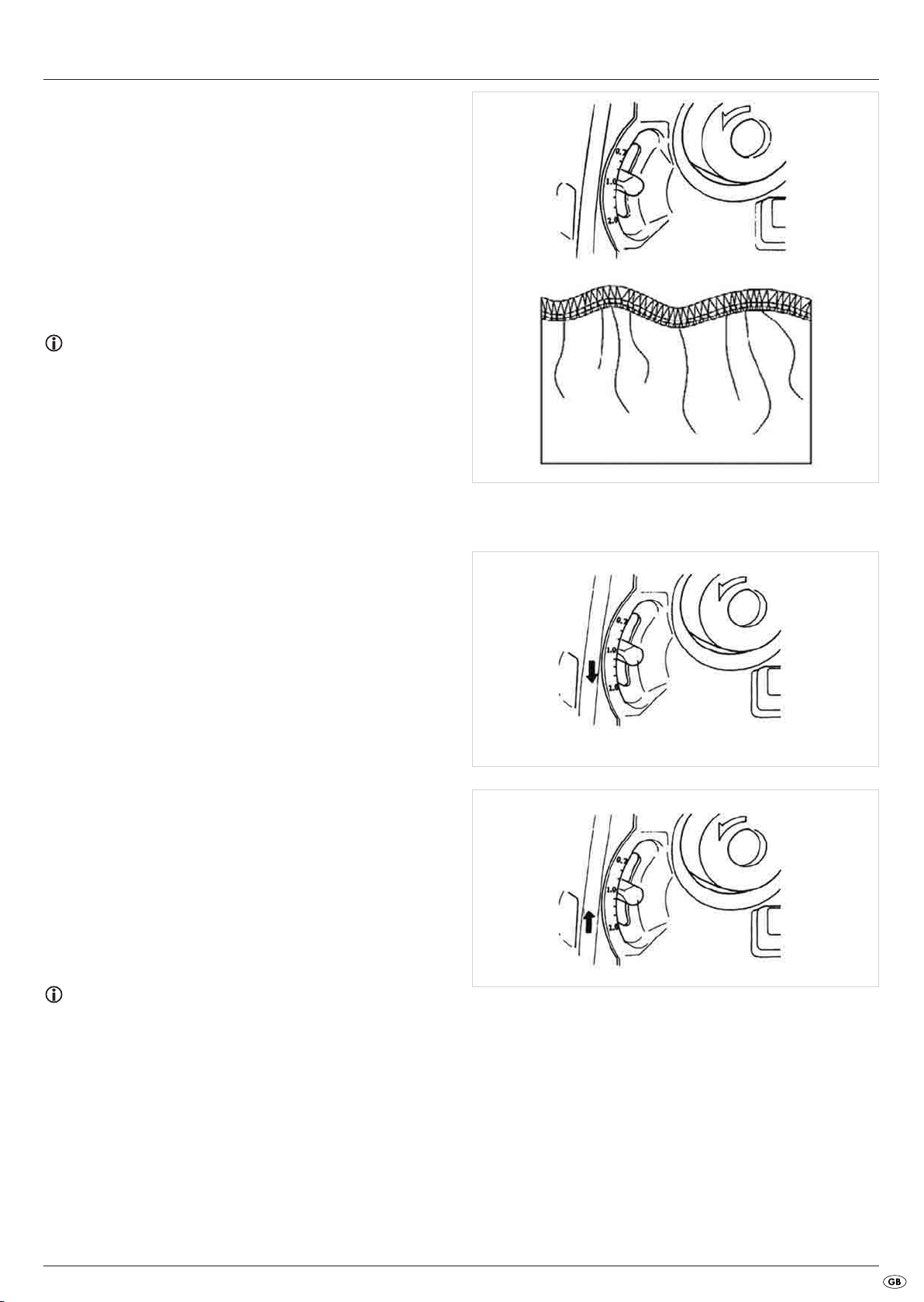
Gathered overlock seam - Settings
The gathered overlock seam is suitable for the ruffling of sleeves, back
upper parts, skirt seams etc.made of elastic materials such as knitwear
and jersey. The individual parts should be brought together before sewing.
• Adjust the differential transport lever 9 to a value higher than 1.0
(Fig. 44). The exact setting depends on the material to be processed
and the desired level of ruffling or gathering.
Therefore always do a sample stitching to test the settings.
Fig. 42
Fig. 43
Stretched overlock seam - Settings
The stretched overlock seam is suitable for the manufacture of ruffles at the
collar, cuffs and skirt edges etc. in soft, stretchy fabric and knitwear.
• Adjust the differential transport lever 9 to a value lower than 1.0 (Fig.
45). The exact setting depends on the material to be processed, and
on the strength of the desired "ruffle effect".
Therefore always do a sample stitching to test the settings.
• Hold the seam down with slight firmness before and behind the sewing
foot a so as to keep the textile under tension.
Note:
If you have set a value of "3" or higher on the adjustment wheel for the
stitch length 5, this setting will automatically return to "3" when you set the
differential transport lever 9 to 2.0.
Fig. 44
Fig. 45
- 17 -
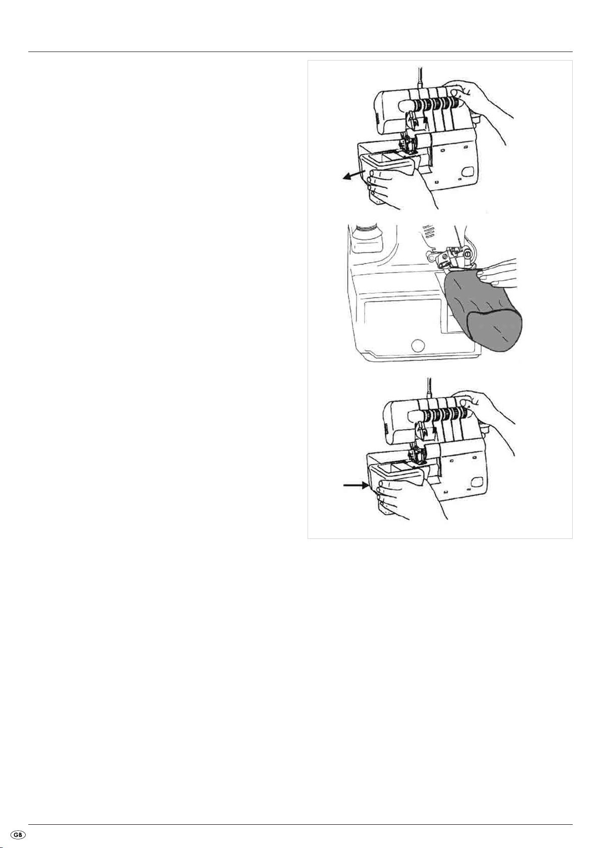
Free arm sewing
To work tubular-shaped fabrics, such as sleeves or trouser legs, you can
remove the free arm cover.
• If appropriate, remove the waste container from the machine.
• Slide the free arm cover to the left and pull it off (Fig. 46)..
• You can now pull the textiles over the free arm w and work them
(Fig. 47).
• To replace the free arm cover, push it onto the free arm w until it clicks
into place and is firmly seated (Fig. 48).
Fig. 46
Fig. 47
Fig. 48
- 18 -
Overlock seams
• Open the front flap 0.
• Slide the seam width switch d to "S", so that the seam width finger is
pushed forward (1) (Fig. 49).
Note:
The seam width switch d must be pushed until it can go no further.
Otherwise, the seams will be untidy.
Standard position
Roll hemmings
• Open the front flap 0.
• Slide the seam width switch d to "R", so that the seam width finger is
pushed backward (1) (Fig. 50).
Note:
The seam width switch d must be pushed until it can go no further,
otherwise the seams will be untidy.
Fig. 49
- 19 -
Roll hem
Fig. 50
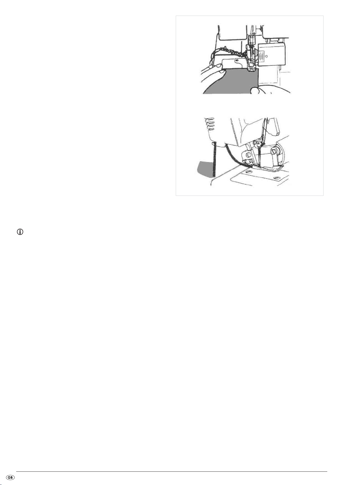
Binding-off and sample sewing
• Lay all yarns under the sewing foot a, to the rear, slightly to the left
and over the stitch plate e.
• Firmly hold the yarns under a slight tension.
• Turn the handwheel 6 2 to 3 revolutions onto itself to begin empty
chainstitch formation.
• Lower the sewing foot a with the sewing foot lever 4.
• Hold the empty chainstitch again firmly and carefully activate the foot
pedal until the empty chainstatch is approximately 5 - 7.5 cm long.
• Place the fabric from the front under the sewing foot a and sew a test
seam (Fig. 51). Under no circumstances should you pull on the textile,
otherwise the needle will be bent or could even break off.
• Continue sewing even after the textile is finished for about 15 to 20 cm.
• Cut the empty chainstitch by using the blade at the rear of the machine
(Fig. 52).
Fig. 51
Fig. 52
Recommended tension settings
Note:
All information about tension settings for the different kinds of stitches are
purely guiding values. The thread tension itself is always dependant
on the type and thickness of the fabric, as well as needle strength and
the strength, type and material composition of the yarn.
It is therefore absolutely necessary to sew a test seam. It is the only way
you can find out if the tension settings are correct, or if they need to be
changed.
- 20 -
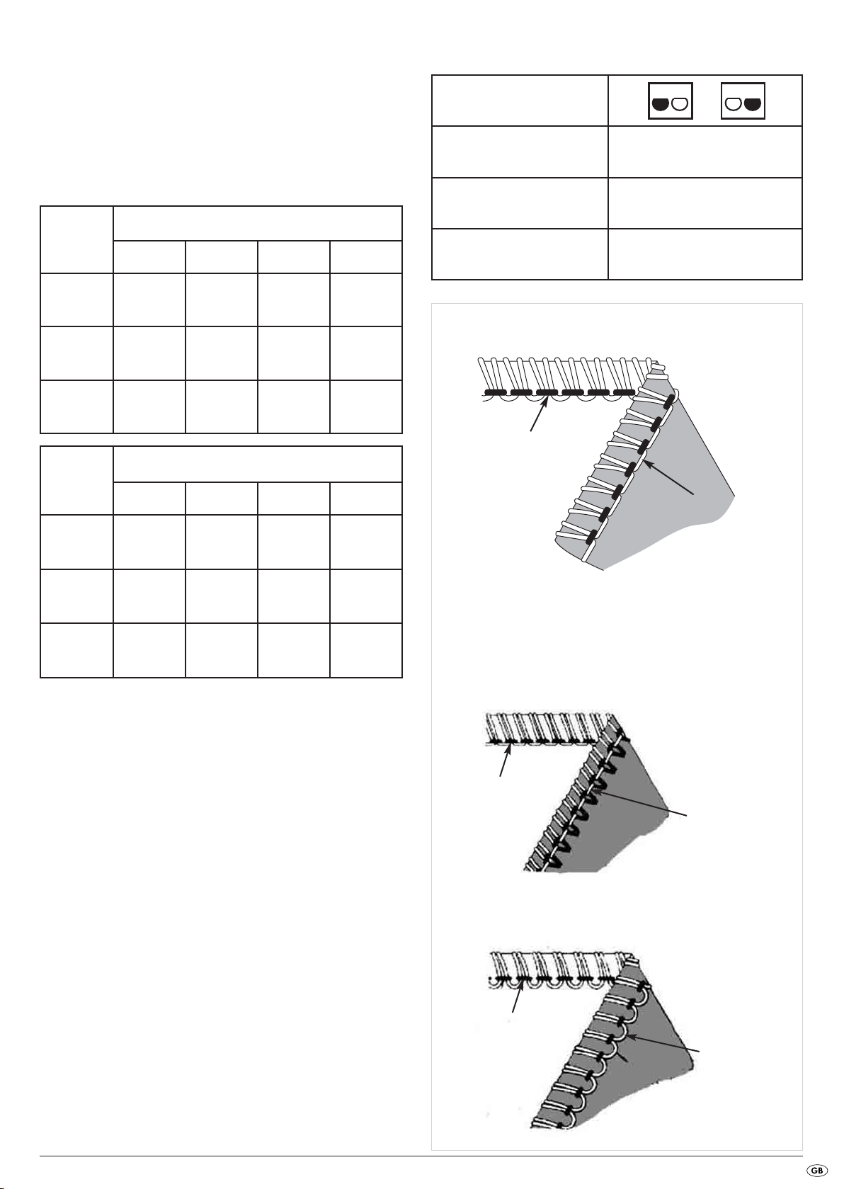
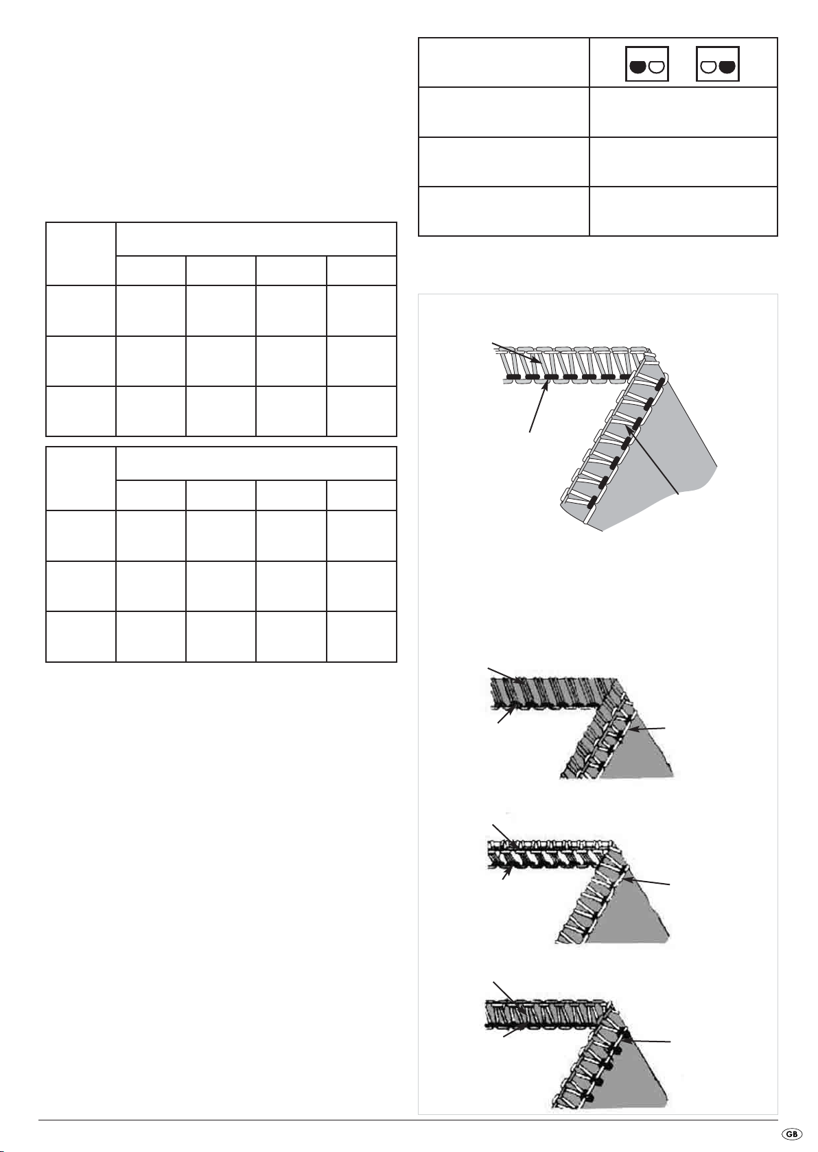
2-thread overcast chain stitch (overlock)
Figure 53 shows you the stitch pattern for this stitch.
This stitch with a needle and 2 threads is used for tidying the edges of
light or stretchy fabrics. By changing the needle position you can obtain a
narrow or a wide overcast seam.
Adjust the thread tension selectors r t z u to the appropriate values
(see table) then sew a test seam on the material being used.
For this type of stitch insert the upper looper element in the upper looper o.
Tensioning the thread
Textiles
blue green red yellow
Needle position
Seam width switch
Stitch length
Upper looper element
S
2 - 4
insert
light
material
medium-
weight
material
heavy
material
Textiles
light material
medium-
weight
material
heavy
material
Inserting the
2.0 -
2.5 -
3.5 -
Tensioning the thread
blue green red yellow
- 1.5
- 1.5
- 3.0
upper looper
element
Inserting the
upper looper
element
Inserting the
upper looper
element
Inserting the
upper looper
element
Inserting the
upper looper
element
Inserting the
upper looper
element
0
0
0.5
0.5
0.5
1.5
needle thread
Top
Correct thread tension
lower looper thread
Underside
Fig. 53
Incorrect thread tension
Should the lower looper yarn appear to be too tight or the needle thread
too loose (Fig. 54) :
• turn the thread tension selector for the lower looper thread u (yellow)
to a lower number, or ...
• turn the thread tension selector for the needle (blue r or green t) to
a higher number.
Should the lower looper yarn appear to be too loose (Fig. 55), turn the
thread tension selector for the lower looper thread u (yellow) to a higher
number.
needle thread
Top
needle thread
Top
lower looper thread
Underside
Fig. 54
Incorrect thread tension
lower looper thread
Underside
Fig. 55
- 21 -
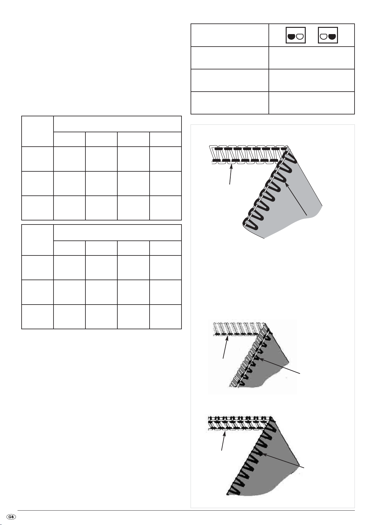
2-thread-overcast-stitch
Figure 56 shows you the stitch pattern for this stitch.
This stitch with a needle and 2 threads is used for tidying normal fabrics
with an overcast stitch. It is also ideal for flat stitch seams (fell or butt seams)
and blind hemming.
By changing the needle position you can obtain a narrow or a wide overcast
seam.
Adjust the thread tension selectors r t z u to the appropriate values
(see table) then sew a test seam on the material being used.
For this type of stitch insert the upper looper element in the upper looper o.
Tensioning the thread
Textiles
blue green red yellow
Needle position
Seam width switch
Stitch length
Upper looper element
Correct thread tension
S
2 - 4
insert
light
material
medium-
weight
material
heavy
material
Textiles
light
material
medium-
weight
material
heavy
material
Inserting the
0.5 -
0.5 -
1.0 -
Tensioning the thread
blue green red yellow
- 1.0
- 1.5
- 1.5
upper looper
element
Inserting the
upper looper
element
Inserting the
upper looper
element
Inserting the
upper looper
element
Inserting the
upper looper
element
Inserting the
upper looper
element
1.0
1.5
1.5
3.0
3.5
3.5
lower looper thread
Top
needle thread
Underside
Fig. 56
Incorrect thread tension
Should the lower looper yarn lie on the underside of the textile (Fig. 57):
• turn the thread tension selector for the lower looper thread u (yellow)
to a higher number, or ...
• turn the thread tension selector for the needle (blue r or green t) to a
lower number.
Should the needle yarn be too loose (Fig. 58):
• turn the thread tension selector for the needle (blue r or green t) to a
higher number.
• turn the thread tension selector for the lower looper thread u (yellow)
to a lower number.
lower looper thread
lower looper thread
- 22 -
Top
Top
Underside
Incorrect thread tension
Underside
needle thread
Fig. 57
needle thread
Fig. 58
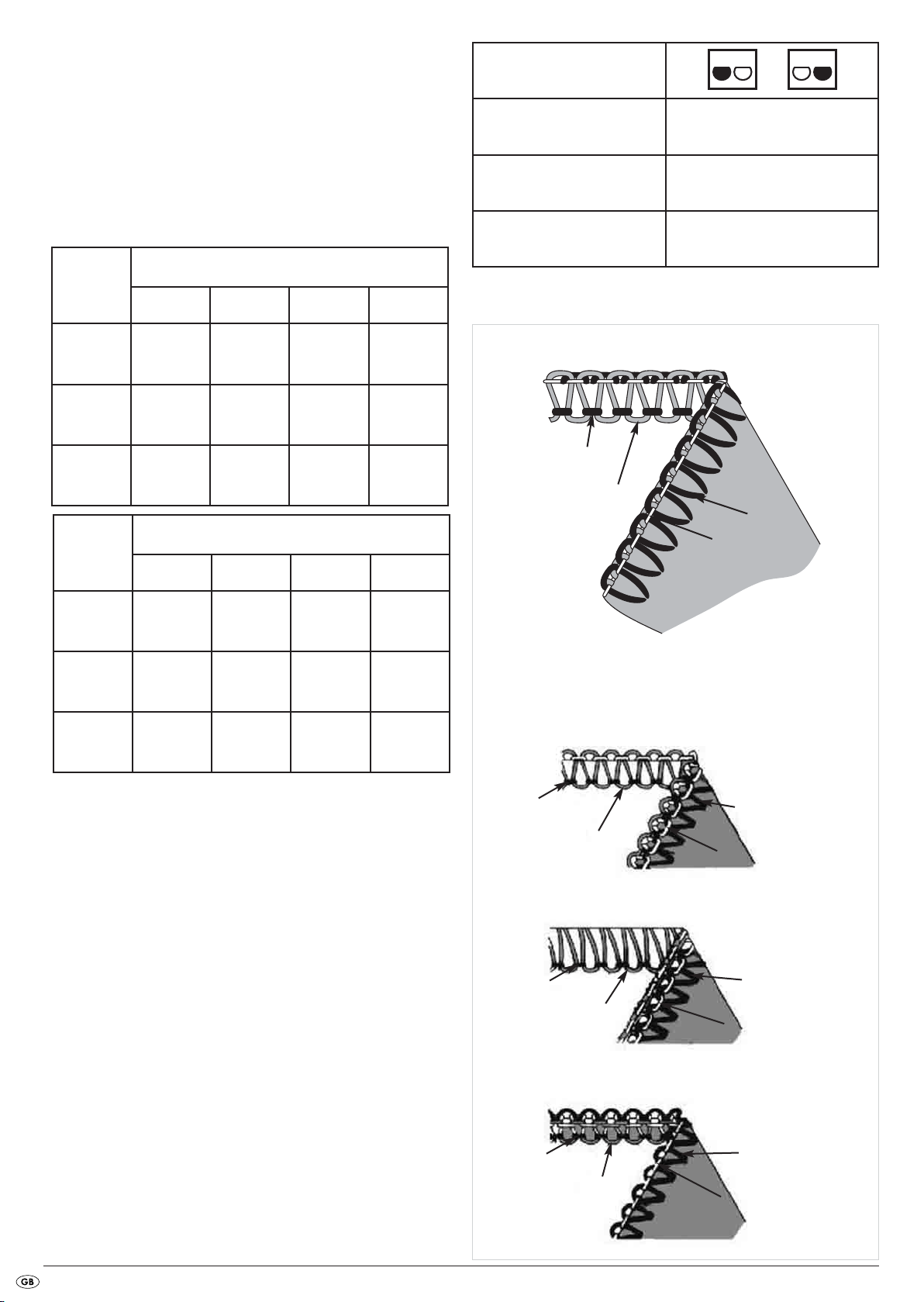
3-thread chain stitch (overlock)
Figure 59 shows you the stitch pattern for this stitch.
This stitch with a needle and 3 threads is used for tidying of normal fabrics
with an overcast stitch.
By changing the needle position you can obtain a narrow or a wide overcast
seam.
Adjust the thread tension selectors r t z u to the appropriate values
(see table) then sew a test seam on the material being used.
Tensioning the thread
Textiles
blue green red yellow
Needle position
Seam width switch
Stitch length
Upper looper element
S
2 - 4
not necessary
light
material
medium-
weight
material
heavy
material
Textiles
light
material
medium-
weight
material
heavy
material
Should the upper looper yarn lie on the underside of the textile (Fig. 60):
• turn the thread tension selector z for the upper looper thread (red) to a
higher number, or ...
• turn the thread tension selector for the lower looper thread u (yellow)
to a lower number.
2.0 - 2.0 1.0
3.0 - 2.0 1.5
3.0 - 3.0 1.5
Tensioning the thread
blue green red yellow
- 2.0 7.0 2.0
- 2.5 6.5 2.5
- 3.5 6.5 2.5
upper looper thread
needle thread
Top
upper looper thread
needle thread
Top
Correct thread tension
lower looper thread
Underside
Fig. 59
Incorrect thread tensions
lower looper thread
Underside
Fig. 60
Should the lower looper yarn lie on the upperside of the textile (Fig. 61):
• turn the thread tension selector for the lower looper thread u (yellow)
to a higher number, or ...
• turn the thread tension selector z for the upper looper thread (red) to a
lower number.
Should the needle thread appear to be too loose (Fig. 62), turn the thread
tension selector for the needle thread (blue r or green t) to a higher
number.
upper looper thread
upper looper thread
- 23 -
needle thread
Top
needle thread
Top
lower looper thread
Underside
Fig. 61
lower looper thread
Underside
Fig. 62
3-thread - flatlock seam
Figure 63 shows you the stitch pattern for this stitch.
This stitch with a needle and 3 threads is used for fell or butt seams and for
ornamental stitches with decorative thread. By changing the needle position
you can obtain a narrow or a wide flatlock seam (flatlock).
Adjust the thread tension selectors r t z u to the appropriate values
(see table) then sew a test seam on the material being used.
Needle position
Seam width switch
Stitch length
S
2 - 4
Textiles
light
material
medium-
weight
material
heavy
material
Textiles
light
material
medium-
weight
material
heavy
material
Tensioning the thread
blue green red yellow
0.5 - 2.5 2.5
0.5 - 2.0 2.0
1.0 - 3.0 3.0
Tensioning the thread
blue green red yellow
- 0 7.0 4.0
- 0.5 7.0 4.0
- 1.0 7.0 4.0
Upper looper element
needle thread
upper looper thread
Top
Incorrect thread tensions
not necessary
Correct thread tension
needle thread
lower looper thread
Underside
Fig. 63
Should the lower looper yarn be too loose (Fig. 64):
• turn the thread tension selector for the lower looper thread u (yellow)
to a higher number, or ...
• turn the thread tension selector for the needle (blue r or green t) to a
lower number.
Should the upper looper yarn be too loose (Fig. 65):
• turn the thread tension selector for the upper looper thread z (red) to a
higher number, or ...
• turn the thread tension selector for the needle (blue r or green t) to a
lower number.
Should the needle yarn be too loose (Fig. 66):
• turn the thread tension selector for the needle (blue r or green t) to a
higher number.
• turn the thread tension selector for the upper looper thread z (red) to a
lower number.
needle thread
upper looper thread
Top
needle thread
upper looper thread
Top
needle thread
upper looper thread
Top
needle thread
lower looper thread
Underside
needle thread
lower looper thread
Underside
needle thread
lower looper thread
Underside
Fig. 64
Fig. 65
Fig. 66
- 24 -
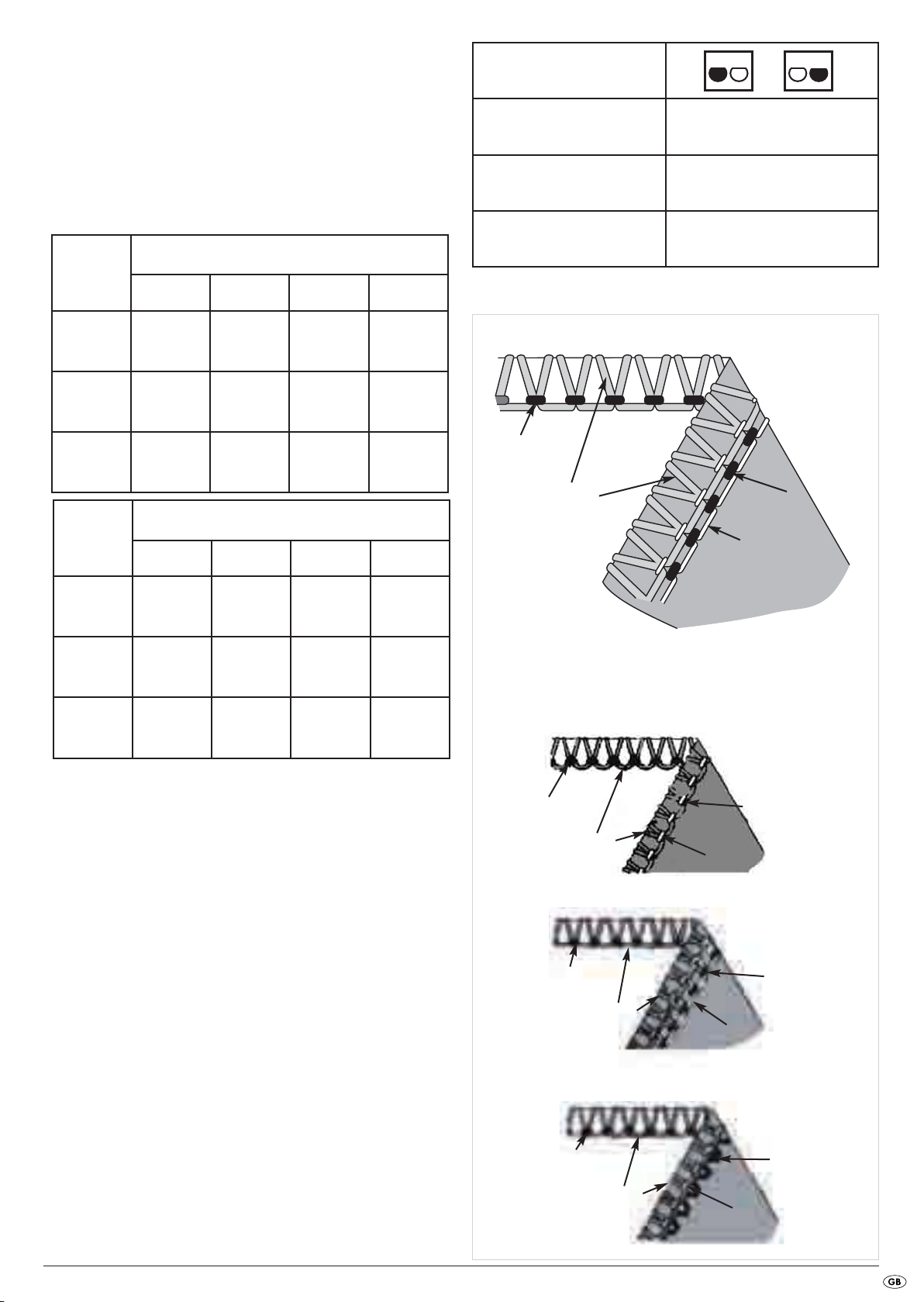
3-thread overcast chain stitch (overlock)
Figure 67 shows you the stitch pattern for this stitch.
This stitch with a needle and 3 threads is used for sewing, for example,
decorative edges.
By changing the needle position you can obtain a narrow or a wide overcast
chain seam.
Adjust the thread tension selectors r t z u to the appropriate values
(see table) then sew a test seam on the material being used.
Needle position
Seam width switch
Stitch length
S
2 - 4
Textiles
light
material
medium-
weight
material
heavy
material
Textiles
light
material
medium-
weight
material
heavy
material
Tensioning the thread
blue green red yellow
2.0 - 0 4.0
3.0 - 0.5 6.5
4.0 - 0.5 7.5
Tensioning the thread
blue green red yellow
- 1.5 0 5.0
- 2.5 1.0 7.0
- 3.0 1.5 8.0
Upper looper element
needle thread
upper looper thread
Top
not necessary
Correct thread tension
needle thread
lower looper thread
Underside
Fig. 67
Incorrect thread tension
Should the upper looper yarn be too loose (Fig. 68):
• turn the thread tension selector for the upper looper thread z (red) to a
higher number.
Should the lower looper yarn be too loose (Fig. 69):
• turn the thread tension selector for the lower looper thread u (yellow)
to a higher number, or ...
• turn the thread tension selector for the upper looper thread z (red) to a
lower number.
Should the needle yarn be too loose (Fig. 70):
• turn the thread tension selector for the needle (blue r or green t) to a
higher number.
• turn the thread tension selector for the upper looper thread z (red) to a
lower number.
needle thread
upper looper thread
Top
needle thread
upper looper thread
Top
needle thread
upper looper thread
Top
Underside
Underside
Underside
needle thread
lower looper thread
Fig. 68
needle thread
lower looper thread
Fig. 69
needle thread
lower looper thread
Fig. 70
- 25 -
3-thread safety stitch, highly elastic, imitated
Figure 71 shows you the stitch pattern for this stitch.
This stitch with 2 needles and 3 threads is ideal for lightweight, extremely
stretchy fabrics such as jersey and spandex.
Adjust the thread tension selectors r t z u to the appropriate values
(see table) then sew a test seam on the material being used.
For this type of stitch insert the upper looper element in the upper looper o.
Needle position
Seam width switch
Stitch length
Upper looper element
S
2 - 4
insert
Tensioning the thread
Textiles
blue green red yellow
light
material
medium-
weight
material
heavy
material
If the lower looper thread is too loose (Fig. 72):
• turn the thread tension selector for the lower looper thread u (yellow)
to a higher number.
2.0 1.5
3.0 2.0
4.0 3.0
Inserting the
upper looper
element
Inserting the
upper looper
element
Inserting the
upper looper
element
0
0.5
1.0
Correct thread tension
Left needle thread
Right needle thread
lower looper thread
Top
Underside
Fig. 71
Incorrect thread tension
Left needle thread
Should the left needle yarn be too loose (Fig. 73):
• turn the thread tension selector for the left needle r (blue) to a higher
number.
Should the right needle yarn be too loose (Fig. 74):
• turn the thread tension selector for the right needle t (green) to a higher
number.
Right needle thread
Top
Left needle thread
Right needle thread
Top
Left needle thread
Right needle thread
Top
lower looper thread
Underside
Fig. 72
lower looper thread
Underside
Fig. 73
lower looper thread
Underside
Fig. 74
- 26 -
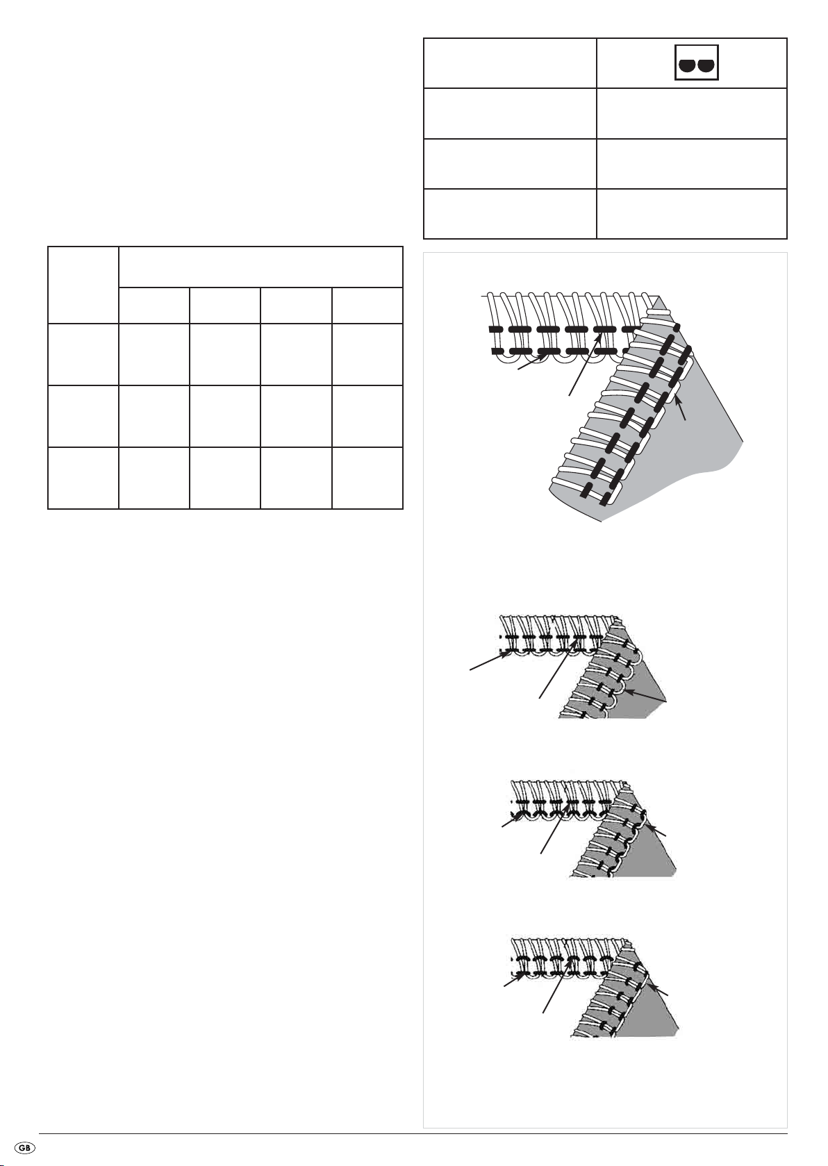
4-thread safety stitch, highly elastic, imitated
Figure 75 shows you the stitch pattern for this stitch.
This stitch with 2 needles and 4 threads is ideal for medium to heavy,
stretchy fabrics such as double-knitted materials and swimwear.
It is suitable for combining two materials and neatening the edges at the
same time.
Adjust the thread tension selectors r t z u to the appropriate values
(see table) then sew a test seam on the material being used.
Tensioning the thread
Textiles
blue green red yellow
Needle position
Seam width switch
Stitch length
Upper looper element
upper looper thread
S
2 - 4
not necessary
Correct thread tension
light material
medium-
weight
material
heavy
material
Should the upper looper yarn lie on the underside of the textile (Fig. 76):
• turn the thread tension selector for the upper looper thread z (red) to a
higher number, or ...
• turn the thread tension selector for the lower looper thread u (yellow)
to a lower number.
Should the lower looper yarn lie on the upperside of the textile (Fig. 77):
• turn the thread tension selector for the lower looper thread u (yellow) to a
higher number, or ...
• turn the thread tension selector for the upper looper thread z (red) to
a lower number.
2.5 2.0 2.5 2.0
3.0 2.0 3.0 2.0
4.0 2.5 4.0 2.5
Right needle thread
Left needle thread
Top
upper looper thread
Right needle thread
Left needle thread
upper looper thread
Right needle thread
Left needle thread
upper looper thread
lower looper thread
Underside
Incorrect thread tension
lower looper thread
Top
Top Underside
Underside
lower looper thread
Fig. 75
Fig. 76
Fig. 77
Should the left needle yarn be too loose (Fig. 78):
• turn the thread tension selector for the left needle r (blue) to a higher
number.
Should the right needle yarn be too loose (Fig. 79):
• turn the thread tension selector for the right needle t (green) to a higher
number.
- 27 -
Right needle thread
Left needle thread
Top
upper looper thread
Right needle thread
Left needle thread
Top
lower looper thread
Underside
Fig. 78
lower looper thread
Underside
Fig. 79
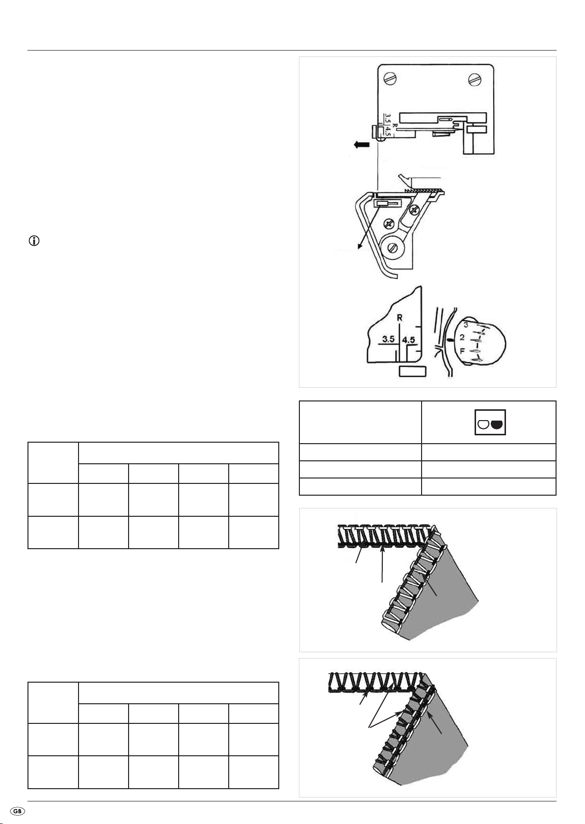
Roll hemmings
With this machine you can sew four different roll hemming types. When
sewing roll hemmings, the fabric edge is folded over and provided with an
overlock seam. Lightweight fabrics such as batiste, chiffon, organza and
so on are best for these kinds of seams. Heavy fabrics or stiff materials are
not suitable for roll hemmings.
• Remove the left needle.
• Set the seam width switch d at "R" (Fig. 80).
• Align the support plate of the seam width finger on the marking "R"
on the stitch plate by turning out the seam width adjustment knob f
(Fig. 81).
• Place the dial for the stitch length 5 at "F - 2" (Fig. 82). With this a fine
seam is sewn.
• For roll hemmings use a needle with specification Nr. 14.
Tips:
• For a rolled hem many different combinations of yarn can be used. To
create a particularly beautiful rolled hem (3-thread rolled hem), use a
bushy yarn (bushy polyamid thread/woolly nylon) as the upper looper
yarn and normal yarn for the needle and lower looper. For a 2-thread
rolled hem use bushy yarn for the lower looper thread and normal yarn
for the needle thread.
• At the start of sewing hold the empty thread chain firmly so that they
cannot roll into the seam.
• Subject the material to slight tension in the sewing direction. This will
make the seam more delicate.
• Before cutting the thread chain close to the textile, apply a small drop
of fabric glue to the seam and allow it to dry. Check for colourfastness
on the textile prior to this.
Roll hem
Fig. 81
Fig. 80
Fig. 82
3-thread rolled hem
Figure 83 shows you the stitch pattern for this stitch.
Upper looper
thread
Polyester
Bushy yarn
Adjust the thread tension selectors t z u to the appropriate values
(see table) then sew a test seam on the material being used.
blue green red yellow
- 2.0 7.5 3.0
- 2.0 2.0 2.0
Tensioning the thread
3-thread upper looper overcast rolled hem
Figure 84 shows you the stitch pattern for this stitch. Adjust the thread tension
selectors t z u to the appropriate values (see table) then sew a test
seam on the material being used.
Upper looper
thread
blue green red yellow
Tensioning the thread
Needle position
Seam width switch
Stitch length
Upper looper element
upper looper thread
needle thread
Top
needle thread
R
F - 2
not necessary
lower looper thread
Underside
Fig. 83
Polyester
Bushy yarn
- 2.0 5.5 7.0
- 2.0 0 2.5
upper looper thread
lower looper thread
Top
Underside
Fig. 84
- 28 -

2-thread rolled hem
Figure 85 shows you the stitch pattern for this stitch.
Adjust the thread tension selectors t u to the appropriate values (see
table) then sew a test seam on the material being used.
For this type of stitch insert the upper looper element in the upper looper o.
Lower looper
thread
Bushy yarn
blue green red yellow
- 1.5
Tensioning the thread
Inserting the
upper looper
element
1.5
Needle position
Seam width switch
Stitch length
Upper looper element
lower looper thread
Top
R
F - 2
insert
needle thread
Underside
Fig. 85
2-thread lower looper overcast rolled hem
Figure 86 shows you the stitch pattern for this stitch..
Adjust the thread tension selectors t u to the appropriate values (see
table) then sew a test seam on the material being used.
For this type of stitch insert the upper looper element in the upper looper o.
Lower looper
thread
Polyester
Bushy yarn
blue green red yellow
- 2.0
- 1.5
Tensioning the thread
Inserting the
upper looper
element
Inserting the
upper looper
element
2.0
1.5
Needle position
Seam width switch
Stitch length
Upper looper element
needle thread
Top
R
F - 2
insert
lower looper thread
Underside
- 29 -
Fig. 86

Flatlock decorative seams
To produce flatlock seams, set up the thread tensions for a 3-thread overlock
stitch. Sew a seam and then pull the fabric apart to smooth the seam.
The flatlock seam can be used as a decorative assembly seam or as pure
ornamental stitching (Fig. 87, dark thread).
Tips:
• Pay attention to proper tension, so that the workpiece can be pulled
well apart after sewing.
• Use a decorative thread as the upper looper thread, since this is the
most important thread and will be clearly visible.
1. Remove the right or the left needle (Fig. 88).
Fig. 87
Fig. 88
2. Set up the recommended tension settings for a 3-thread overlock seam
(Fig. 89).
3. Then readjust the upper thread tensions (green or blue) so that they are
much looser.
4. Now also release the thread tension of the upper looper (red) somewhat.
5. Then adjust the thread tension of the lower looper (yellow) considerably
tighter.
Flatlock seam as assembly seam
• Place the two fabrics to be sewn inside out to each other, so as to create
a decorative seam on the front side.
• Sew the seam and while doing this cut away the excess fabric (Fig. 90).
Fig. 89
Fig. 90
Figure 91 shows you the stitch pattern for this stitch.
• The upper thread (needle thread) (green or blue) then has a V-shaped
pattern on the inside of the fabric.
• The lower looper thread runs as a straight line along the fabric edge.
• Pull the fabric apart on both sides of the seam, so that the stitches lie
flat.
- 30 -
needle thread
upper looper thread
Top
lower looper
thread
Underside
Fig. 91

Flatlock seam as decorative seam
• Adjust the movable upper blade i into a rest position (Fig. 92).
The textile is not trimmed in this type of seam.
• Fold the textile so that the two inside sides lie on each other.
• Place the textile so that a portion of the stitch is sewn outside of the
textile (Fig. 93).
•Sew the seam.
• Then fold the textiles apart. The stitches will then lie flat.
Overlock blind hems
The overlock blind hem is best suited for knitwear. It creates a durable
edgetidying and is hardly noticeable (Fig. 94).
In one operation the protruding material is cut away, the hem is sewn and
the edges are provided with an overlock seam.
Fig. 92
Fig. 93
1. Remove the left needle and set the machine up for a narrow 3-thread
overlock seam.
2. Set the stitch length to 4 mm.
3. Fold the hem, first to the inside and then to the outside of the fabric, so
that the fabric edge stands 6 mm above the first fold (Fig. 95).
4. Sew carefully on the fold. Thereby, the needle must pierce straight into
the edge of the fold.
Pin tucks
To render your decorative garment as more creative, it can be provided
with pin tucks before trimming (Fig. 96). Pin tucks are ornamental seams, as
shown in the figure 96.
1. Remove the left needle and set the machine up for a narrow 3-thread overlock seam.
2. Adjust the upper blade i into the rest position.
3. To achieve a uniform result, mark the desired number of pin-tucks on the
fabric with water-soluble fabric pen or fabric chalk.
4. Fold the fabric inside out and sew it.
5. When all of the tucks are sewn, iron them all in one direction so that
they lie evenly flat.
Fig. 94
Fig. 95
- 31 -
Fig. 96

Sewing corners
Outer corners
1. Cut away, before and after the corner, about 2 cm to the seam line
(Fig. 97).
2. Sew a stitch further than to the marking "A" on the drawing and then
stop (Fig. 97).
3. Lift the needle and sewing foot a.
4. Pull the fabric to the rear, such that the yarn being held by the finger of
the stitch plate e is released. (For better recognition, on the drawing
opposite the sewing foot a is not shown - Figure 98).
5. Rotate the workpiece and lower the sewing foot a so that the upper
blade i lies in a line with the cutting edge (Fig. 99).
6. Pull the loose threads up and continue to sew.
Fig. 98
Cutting line
Fig. 97
Fig. 99
Inner corners
1. Cut the fabric away from the seam edge.
2. Adjust the upper blade i into the rest position (Fig. 100).
3. Sew on the cutting edge (Fig. 101).
4. Stop sewing just before reaching the corner.
5. Place a fold on the corner, so that the two edges form a line (Fig. 102).
6. Sew slowly over the corner and along the second edge. Ensure that you do
not include the fold!
Fig. 100
Fig. 101
- 32 -
Fig. 102

Tips and Tricks
Using pins
Always insert pins to the left of the sewing foot a (Fig. 103).
The pins are thus not in the cutting area of the blade i s and they can
be easily removed afterwards.
Attention! Appliance Damage!
NEVER sew over pins or other hard materials. The blade i s could be
irreparably damaged!
Secure empty threads
To prevent the loosening of an empty thread chain, you should thread the
empty thread chain into a hand-sewing needle. For security, insert the
needle into the end of the seam.
Seam reinforcement
The seam can be strengthened if it is sewn with a reinforcing strip.
To do this, guide the strip through the slot in the front area of the sewing
foot a (Fig. 104).
Fig. 103
Place the strip under the foot and to the rear and then sew the seam.
Thus the strip is sewn into the seam (Fig. 105).
Edging
1. Adjust the upper blade i into the rest position.
2. Remove the right needle and its thread.
3. Pull the cord inlay (yarn or reinforcing strip) through the slot in the front
of the sewing foot a (Fig. 106).
Fig. 104
Fig. 105
4. Lay the cord inlay under the sewing foot a and chainstitch the desired
length (Fig. 107).
You can use the chainstitched edgings individually or weave several together.
Fig. 106
Fig. 107
- 33 -

Maintenance and Cleaning
Attention!
Before cleaning or carrying out maintenance, ALWAYS remove the plug
from the mains power socket. This prevents an unintended starting of the
machine. If you do not, you run a risk of serious injury!
Cleaning and lubrication
• Regularly remove dust and lint from the looper and blade areas.
For this you can use the supplied brush (Fig. 108).
• Wipe the machine with a lightly moistened cloth.
• Lubricate the machine regularly at the lubrication points shown on
Figure 109. For this use exclusively sewing machine oil.
Fig. 108
Exchanging the lower blade
Attention!
Before changing the blade s ALWAYS remove the plug from the mains
power socket. This prevents an unintended starting of the machine. If you
do not, you run a risk of serious injury!
Change the lower blade s as soon as you notice that the lower blade s
no longer provides accurate and clean cuts. Use Figure 110 for assistance.
1. Open the front flap 0.
2. Adjust the upper blade i into the rest position (A).
3. Remove the screw on the lower blade s (B) and remove the blade s
(C) (Fig. 111).
4. Slide the new blade s into the retainer and then tighten it with the
screws.
5. Place the upper blade i in the work position and close the front flap 0.
Fig. 109
Fig. 110
- 34 -
Fig. 111

Storage
IMPORTANT:
ALWAYS remove the plug from the mains power socket before putting the
machine into storage. This prevents an unintentional starting of the appliance,
and thus the risk of injury, as well as an overheating of it!
When the machine is not in use, always cover it with the hood. This will
protect the machine from dust. Store the machine at a clean and dry
location.
Always transport the machine with the fold-out handle.
Disposal
Do not dispose of the appliance in your normal domestic
waste. This product is subject to the provisions of European
Directive 2002/96/EC.
Dispose of the appliance through an approved disposal centre or at your
community waste facility.
Observe the currently applicable regulations. In case of doubt, please
contact your waste disposal centre.
Warranty and Service
You receive a 3-year warranty for this appliance as of the purchase date.
This appliance has been manufactured with care and meticulously examined
before delivery.
Please retain your receipt as proof of purchase. In the case of a warranty
claim, please make contact by telephone with our service department.
Only in this way can a post-free despatch for your goods be assured.
The warranty covers only claims for material and maufacturing defects, not
for transport damage, wearing parts or for damage to fragile components,
e.g. buttons or batteries. This product is for private use only and is not intended
for commercial applications.
In the event of misuse and improper handling, use of force and interference
not carried out by our authorized service branch, the warranty will become
void.. Your statutory rights are not restricted in any way by this warranty.
The warranty is not extended by repairs made under warranty. This also applies to replaced and repaired parts. Damages and defects extant on purchase must be reported immediately after unpacking, at latest by two days
after the purchase date. Repairs carried out after expiry of the
warranty period are subject to charge.
Dispose of the packaging materials in an environmentally
responsible manner.
Under no circumstances should you dispose of the sewing machine oil with
household waste. Do not pour it down the drain. Dispose of the machine oil
through an approved disposal centre or at your community waste facility.
Service Great Britain
Tel.: 0871 5000 720
E-Mail: kompernass@lidl.gb
Service Ireland
Tel.: 1890 930 034
(0,08 EUR/Min., (peak))
(0,06 EUR/Min., (off peak))
E-Mail: kompernass@lidl.ie
(£ 0.10/Min.)
Importer
KOMPERNASS GMBH
BURGSTRASSE 21
44867 BOCHUM, GERMANY
www.kompernass.com
- 35 -

Troubleshooting
Problem Cause Solution
Needles break
Thread breaks
Stitches are omitted
Stitches are irregular
• Needles are bent, blunt or damaged at the
points.
• Needles are not correctly inserted. • Insert the needles into the retainers correctly.
• You have pulled the material too heftily. • Carefully guide the material with both hands.
• Yarn has not been correctly threaded. • Thread the yarn correctly.
• Thread tension is too high. • Reduce the thread tension.
• Needles are not correctly inserted. • Insert the needles into the retainers correctly.
• Needles are bent, blunt or damaged at the
points.
• Needles are not correctly inserted. • Insert the needles into the retainers correctly.
• Yarn has not been correctly threaded. • Check the course of the individual threads.
• Thread tension is not correct. • Correct the thread tension.
• Thread is trapped. • Check the course of the individual threads.
• Fit new needles.
• Fit new needles.
• Thread tension is too high. • Adjust the thread tension.
Seams cause wrinkles
Material is not cut off cleanly • Blades are blunt or improperly fitted. • Exchange the blade or reinsert it correctly.
Material edges ruffle themselves • Too much material in a stitch. • Altering the seam width.
• Yarn has not been correctly threaded. • Thread the yarn correctly.
• Thread is blocked. • Check the course of the individual threads.
• Differential feed motion not adjusted. • Correctly adjust the differential transport.
- 36 -

Spis treści Strona
Użytkowanie zgodne z przeznaczeniem 39
Wskazówki dotyczące bezpieczeństwa 39
Zakres dostawy 40
Dane techniczne 40
Opis urządzenia 41
Ustawianie noża górnego w położeniu spoczynkowym 41
Informacje o igłach 41
Wkład do chwytacza górnego 41
Otwieranie klapy czołowej 42
Czynności przygotowawcze 42
Podłączanie pedału 42
Sterowanie prędkością szycia 42
Wyłącznik bezpieczeństwa 42
Dołączanie pojemnika na odpadki 42
Zdejmowanie igły(igieł) 43
Zakładanie igły(igieł) 43
Obsługa koła 43
Ustawianie wysięgnika nitek 43
Nawlekanie 44
Ogólne wskazówki dotyczące nawlekania 44
Nawlekanie górnej nitki chwytacza (czerwony) 44
Nawlekanie dolnej nitki chwytacza (żółty) 46
Nawlekanie nitki prawej igły (zielony) 47
Nawlekanie nitki lewej igły (niebieski) 49
Szycie próbne 50
Zmiana nitki (wiązanie) 51
Ustawianie długości ściegu 51
Ustawianie szerokości szwu 51
... przy użyciu prawej lub lewej igły 51
... poprzez obracanie pokrętłem regulacji szerokości szwu 52
Ustawianie pokrętła regulacji szerokości szwu 52
Ustawianie docisku stopki 52
Transport różnicowy 53
Zasada działania 53
Szew owerlokowy marszczony – ustawienia 53
Szew owerlokowy rozciągliwy – ustawienia 53
Szycie z wolnym ramieniem 54
Przed pierwszym użyciem zapoznaj się z instrukcją obsługi i zachowaj ją w celu późniejszego wykorzystania. W przypadku przekazania urządzenia osobom trzecim należy przekazać im także instrukcję.
- 37 -

Szwy owerlokowe 55
Obrzucanie ściegiem 55
Szycie na okrętkę i szycie próbne 56
Zalecane ustawienia naciągu 56
2-nitkowy ścieg obrębiający rulonowy (owerlokowy) 57
2-nitkowy ścieg obrzucający 58
3-nitkowy ścieg obrzucający 59
3-nitkowy szew płaski typu flatlock 60
3-nitkowy ścieg obrzucający rulonowy (owerlokowy) 61
3-nitkowy ścieg zabezpieczający, bardzo rozciągliwy, imitowany 62
4-nitkowy ścieg zabezpieczający, bardzo rozciągliwy, imitowany 63
Obrzucanie ściegiem 64
3-nitkowe obrzucanie ściegiem 64
3-nitkowe obrzucanie ściegiem rulonowe chwytaczemem górnym 64
2-nitkowe obrzucanie ściegiem 65
2-nitkowe obrzucanie ściegiem rulonowe chwytaczemem dolnym 65
Szwy płaskie dekoracyjne typu flatlock 66
Szew płaski typu flatlock jako szew montażowy 66
Szew płaski jako szew dekoracyjny 67
Owerlokowe obrzucanie brzegów 67
Pasemka 67
Szycie narożników 68
Narożniki zewnętrzne 68
Narożniki wewnętrzne 68
Wskazówki i porady 69
Fastrygowanie 69
Zabezpieczanie pustego łańcuszka 69
Wzmacnianie szwu 69
Naszywki 69
Konserwacja i czyszczenie 70
Czyszczenie i smarowanie 70
Wymiana noża dolnego 70
Przechowywanie 71
Usuwanie/wyrzucanie 71
Gwarancja i serwis 71
Importer 71
Usuwanie usterek 72
- 38 -

MASZYNA DO SZYCIA ZE ŚCIEGIEM OWERLOK
Użytkowanie zgodne z przeznaczeniem
Owerlokowa maszyna do szycia służy do ...
– użytku jako urządzenie mobilne;
– do obszywania brzegów materiałów (ścieg okrętkowy) ...
– wyłącznie do użytku w prywatnych gospodarstwach domowych.
Wskazówki dotyczące bezpieczeństwa
W przypadku maszyny do szycia można odnieść obrażenia i narazić się
na niebezpieczeństwo utraty życia, jak w przypadku każdego innego urządzenia elektrycznego. By tego uniknąć, a także by
praca była bezpieczna:
• Przy opuszczaniu maszyny należy zawsze wyciągnąć wtyczkę sieciową
z gniazdka.
Zapobiega to niebezpieczeństwu wypadku przez przypadkowe włączenie.
• Przed przystąpieniem do konserwacji, najpierw wyciągnij wtyczkę z
gniazdka. Zapobiega to zagrożeniu dla życia przez porażenie prądem
elektrycznym. Lampki diodowej nie można wymienić.
• Nigdy nie wyciągać wtyczki z gniazdka, ciągnąc za kabel. Przy wyciąganiu należy zawsze chwytać za wtyczkę, nigdy za kabel.
• Maszyny do szycia należy używać tylko w suchych pomieszczeniach.
• Naprawę uszkodzonej wtyczki lub kabla sieciowego niezwłocznie zleć
wykwalifikowanemu personelowi lub serwisowi klienta.
• Urządzenie nie jest przeznaczone do użytkowania przez osoby (w
tym dzieci) z ograniczoną sprawnością fizyczną, sensoryczną bądź umysłową lub nieposiadające doświadczenia i / lub wiedzy, chyba
że będą one przebywały pod opieką osoby odpowiedzialnej za ich
bezpieczeństwo lub uzyskają od niej wskazówki dotyczące właściwego
używania urządzenia.
• Nie można pozwolić dzieciom na zabawę urządzeniem.
• Nigdy nie używać maszyny z zablokowanymi otworami wentylacyjnymi.
Otwory wentylacyjne maszyny oraz pedał należy czyścić z kłaczków,
kurzu i resztek tkanin.
• W przypadku uszkodzenia przewodu przyłączeniowego,połączonego
z pedałem, przewód należy przekazać producentowi lub serwisowi
technicznemu w celu wymiany uszkodzonego przewodu.
Maszyna do szycia nie nadaje się ...
– do ustawienia stacjonarnego,
– do obróbki innych materiałów (np. skóry, tkaniny namiotów, żagli itp),
– do użytku komercyjnego i przemysłowego.
Ostrzeżenie przed obrażeniami i szkodami
materialnymi:
• Należy utrzymywać porządek w obszarze pracy. Nieporządek w
obszarze pracy może powodować wypadki.
• Zadbać o dobre oświetlenie podczas pracy!
• Nie nosić luźnego ubrania ani biżuterii, gdyż mogą one zostać wciągnięte
przez ruchome części. Osoby z długimi włosami powinny nosić siatkę
na włosach.
• Unikać przyjmowania nienaturalnej sylwetki ciała. Zawsze dbać o pewne
podparcie i stałe zachowanie równowagi.
• Producent nie odpowiada za szkody z tytułu wypadków, spowodowanych przez niewystarczającą staranność przy obchodzeniu się z urządzeniem lub nieprzestrzeganiem wskazówek bezpieczeństwa, podanych w instrukcji obsługi.
• Nie zasłaniać otworów wentylacyjnych! Zagrożenie przegrzania!
• Olej do maszyny do szycia trzymaj z dala od dzieci.
• W razie połknięcia oleju lub dostania się do oczu natychmiast zgłosić
się do lekarz.
- 39 -

Zakres dostawy
Owerlokowa maszyna do szycia
Olej
Pojemnik na odpadki
Pudełko z akcesoriami
Instrukcja obsługi
nóż zapasowy (dolny)
2 igły nr 11
4 igły nr 14
(2 założone
w maszynie)
4 zatyczki szpulek
wkład do chwytacza
górnego
śrubokręt mały
śrubokręt duży
pokrywa
Akcesoria znajdziesz w pudełku z boku maszyny (rys. 1).
Dane techniczne
Liczba nitek 2, 3 lub 4
Liczba igieł 2 lub 1
Prędkość szycia ok. 1200 obr./min.
Szerokość ściegu
prawy: 3,0 mm – 4,5 mm
lewy: 5,2 mm – 6,7 mm
Długość ściegu 1 – 4 mm
Igły HA x 1 nr 11-14 lub 130/705 nr 75-90
Pobór mocy : 90 W
Napięcie nominalne: 220–240 V ~, 50 Hz
Klasa ochrony: II
pęseta
pędzelek
Rys.1
Poziom hałasu w normalnych warunkach użytkowania wynosi 78 dB(A).
Pedał
Do tej maszyny używaj wyłącznie dołączonego pedału:
- ELECTRONIC FDM Speed Controller
- Typ KD-2902
- 40 -

Opis urządzenia
Na przedniej stronie rozkładanej:
1 prowadnik nici
2 trzpień szpulki
3 centrowanie szpulki
4 dźwignia stopki
5 pokrętło regulacyjne długości ściegu
6 koło
7 przyłącze pedału/przyłącze sieciowe
8 wyłącznik sieciowy (wyłącznik On/Off)
9 dźwignia transportu różnicowego
0 klapka czołowa
q płytka palca ściegowego
w wolne ramię
e płytka ściegowa
r nastawnik naciągu nitki (lewa nitka)
t nastawnik naciągu nitki (prawa nitka)
z nastawnik naciągu nitki (chwytacz górny)
u nastawnik naciągu nitki (chwytacz dolny)
Na tylnej stronie rozkładanej:
i ruchomy nóż górny (nóż górny)
o chwytacz górny
p chwytacz dolny
a stopka
s stały nóż dolny
d nastawnik szerokości szwu
f pokrętło regulacji szerokości szwu
Ustawianie noża górnego w położeniu spoczynkowym
W określonych rodzajach szwów lub w celu łatwiejszej obsługi pokrętła
regulacji szerokości szwu f należy nóż górny i ustawić w położenie
spoczynkowe.
W tym celu nóż górny i przesuń w prawo i przekręć go nieco aż do
unieruchomienia (rys. 2 i 3).
Informacje o igłach
W tej maszynie stosuje się dostępne w sprzedaży płaskie igły szwalnicze.
Tych igieł nie można pomyłkowo założyć. Igły te są oferowane w
specjalistycznych sklepach.
Do maszyny pasują igły o rozmiarach 11 i 14.
W poniższej tabeli przedstawiono w skrócie różnice przy używaniu igły
(szczegółowe informacje na ten temat, zobacz rozdział „Ustawianie szerokości
szwu“).
Wkład do chwytacza górnego
Do wykonania niektórych rodzajów ściegów potrzebny jest wkład do
chwytacza górnego. W opisach do poszczególnych rodzajów ściegów
zamieszczono informację o tym, czy jest potrzebne założenie wkładu do chwytacza górnego.
Włóż mały drucik od tyłu w ucho chwytacza górnego o i plastikowy, natomiast z drugiej strony plastikowy trzpień od przodu w otwór w chwytaczu górnym
o (rys. 4a).
Wkład do chwytacza górnego możesz przechowywać w schowku za klapą
czołową 0 (rys. 4b).
Rys. 2
szerokość szwu 3,5 mm 5,7 mm
używana igła prawa igła lewa igła
nastawnik naciągu nitki zielony niebieski
Rys. 4a
Rys. 3
Rys. 4b
- 41 -

Otwieranie klapy czołowej
Uwaga!
Zawsze najpierw wyłącz maszynę do szycia wyłącznikiem sieciowym 8
zanim otworzysz klapę czołową 0. Niebezpieczeństwo odniesienia obrażeń.
• Przesuń klapę czołową 0 w prawo (A), a następnie pociągnij do
siebie (B) (rys. 5). Za klapą czołową 0 zobaczysz przestrzeń
chwytaczy.
UWAGA:
W trakcie szycia klapa czołowa 0 musi być zawsze zamknięta!
Czynności przygotowawcze
Maszynę owerlokową ustaw na stabilnej, równej powierzchni.
Zwróć uwagę na to, czy na miejscu pracy jest zapewnione dostateczne
oświetlenie.
Podłączanie pedału
• Podłącz wtyczkę pedału do przyłącza pedału 7.
• Podłącz wtyczkę do gniazdka zasilania.
W celu włączenia maszyny naciśnij wyłącznik sieciowy 8.
Uwaga!
Oddalając się z miejsca pracy lub przed przystąpieniem do konserwacji,
zawsze wyjmuj wtyczkę sieciową z gniazdka. Niebezpieczeństwo odniesienia obrażeń.
Sterowanie prędkością szycia
Prędkością szycia steruje się za pośrednictwem pedału. Prędkością szycia
steruje się poprzez mocniejszy lub słabszy nacisk na pedał.
Rys.5
Wyłącznik bezpieczeństwa
Maszyna została wyposażona w mikrowyłącznik bezpieczeństwa. Przy
otwartej klapie czołowej 0 uruchomienie maszyny nie jest możliwe.
Przed przystąpieniem do szycia zamknij klapę czołową 0.
Dołączanie pojemnika na odpadki
W czasie pracy do pojemnika na odpadki wpadają wszystkie resztki
materiałów, co pozwala utrzymać czystość w miejscu pracy.
• Najpierw wsuń obie blokady (A) w otwory mocujące (B) (rys. 6).
• Następnie obie blokady (C) wprowadź w otwory mocujące (D)
(rys. 7).
• By ponownie zdjąć pojemnik na odpadki, pojemnik przesuń do przodu
i nieco nachyl (rys. 8).
Rys.6
Rys.7
- 42 -
Rys.8

Zdejmowanie igły(igieł)
Porada
Uwaga!
Przed przystąpieniem do wymiany igły, najpierw wyjmij wtyczkę z gniazdka.
Uniemożliwi to przypadkowe uruchomienie urządzenia. W przeciwnym
razie powstaje niebezpieczeństwo odniesienia obrażeń!
P
Wymiana igieł przebiega sprawniej po uprzednim zdjęciu pokrywy wolnego
ramienia (rys. 9a)!
1. Obracaj kołem 6 do siebie, aż igły znajdą się w najwyższym położeniu (rys. 9b).
2. Małym śrubokrętem odkręć śruby igły dotąd, aż będziesz mógł wyciągnąć
igłę (rys. 10).
3. Zdejmowanie igieł.
Zakładanie igły(igieł)
Uwaga!
Przed przystąpieniem do wymiany igły, najpierw wyjmij wtyczkę z gniazdka.
Uniemożliwi to przypadkowe uruchomienie urządzenia. W przeciwnym
razie powstaje niebezpieczeństwo odniesienia obrażeń!
1. Chwyć igłę spłaszczoną stroną skierowaną do tyłu.
2. Igłę wsuń maksymalnie w uchwyt igły.
3. Małym śrubokrętem dokręć śruby igły (rys. 10).
Obsługa koła
UWAGA:
Obracaj kołem 6 zawsze do siebie (rys. 9b).
Rys. 9a
Rys. 9b
Rys.10
Ustawianie wysięgnika nitek
• Przed nawleczeniem wyciągnij do końca prowadnik nitek 1 (rys. 11).
• Prowadnik nitek 1 obróć 2 taki sposób, by prowadniki sitki znajdowały
się na trzpieniami szpulki.
• W prawidłowym położeni oba elementy przegubowe prowadnika nici 1
muszą się zatrzasnąć z charakterystyczni zatrzasnąć.
• Załóż szpulki nici na centrowanie szpulki.
Centrowanie szpulek nici obowiązuje w przypadku braku szpulek przemysłowych. Klapkę w każdej ze szpulki wsuń na krążek nici (rys. 12).
W ten sposób przy szyciu klapka będzie się trzymała na swoim miejscu.
Rys.11
Rys.12
- 43 -

Nawlekanie
143 2
UWAGA:
W zestawie z maszyną znajdują się 4 igły. Można przystąpić do szycia
zaraz po włączeniu maszyny. By zmienić nitkę, przy stale przewleczonych
nitkach, zapoznaj się z rozdziałem „Zmiana nitki (wiązanie)“.
W razie konieczności nawleczenia całkiem nowej nitki, postąpić, jak
opisano w rozdziale „Nawlekanie“.
Ogólne wskazówki dotyczące nawlekania
Uwaga!
Przed przystąpieniem do nawlekania wyłącznik sieciowy 8 zawsze
ustaw na „O“ (wył.) i wyjmij wtyczkę z gniazdka. Uniemożliwi to przypadkowe uruchomienie urządzenia. W przeciwnym razie powstaje niebezpieczeństwo odniesienia obrażeń!
Prawidłowe nawlekanie decyduje o regularności późniejszych ściegów,
a także o braku zrywania się nitki.
Za klapą czołową 0 znajduje się wykres z instrukcją nawlekania.
Dodatkowo różnymi kolorami pokazano biegi poszczególnej nitki.
W pudełku z akcesoriami znajduje się pęseta, która ułatwia nawlekanie.
Nawlekanie odbywa się w następującej kolejności (rys. 13/14):
1. Pierwszy etap: Górna nitka chwytacza (czerwony)
2. Drugi etap: Dolna nitka chwytacza (żółty)
3. Trzeci etap: Nitka prawej igły (zielony)
4. Czwarty etap: Nitka lewej igły (niebieski)
UWAGA:
Po nawleczeniu wszystkich nitek i zwolnieniu dolnej nitki chwytacza,
postąpić według następującego opisu:
• Odwiń obie nitki igieł.
• Następnie nawiń dolną nitkę chwytacza.
• Dopiero wtedy nawiń ponownie nitki obu igieł.
Igły nawleka się zawsze na końcu!
W celu ułatwienia pracy, poszczególne etapy ponumerowano na rysunkach.
Nawlekanie górnej nitki chwytacza (czerwony)
Rys.13
Rys.14
Uwaga!
Przed przystąpieniem do nawlekania wyłącznik sieciowy 8 obowiązkowo
ustaw w położenie „O“ (wył.) i wyjmij wtyczkę z gniazdka.Uniemożliwi to
przypadkowe uruchomienie urządzenia. W przeciwnym razie powstaje
niebezpieczeństwo odniesienia obrażeń!
Wykorzystaj do pomocy rysunki pokazane obok.
Na rysunku 15 przedstawiono bieg górnej nitki chwytacza. Poszczególne
miejsca nawlekania zostały ponumerowane i opisane poniżej.
1. Otwórz klapę czołową 0.
2. Przeciągnij nitkę od tyłu do przodu przez prowadnik 1 (1).
Rys.15
- 44 -

3. Nawlecz nitkę na prowadnicę, ciągnąc nitkę w dół, aż wślizgnie się
pod prowadnicę (2) (rys. 16).
Rys.16
4. Przytrzymaj nitkę palcami, wsuń ją między tarcze nastawnika naciągu
nitki z, a następnie pociągnij nitkę w dół (3) (rys. 17).
UWAGA:
Nitka musi przebiegać prawidłowo między dwiema tarczami nastawnika
naciągu nitki z.
5. Nawlecz nitkę w obszarze chwytacza, jak pokazują czerwone zaznaczenia (5–7) (rys. 18).
6. Przeciągnij nitkę od przodu do tyłu przez chwytacz górny o (8).
7. Przeciągnij około 10 cm nitki przez chwytacz i połóż nitkę na płytce
ściegowej e.
Rys.17
- 45 -
Rys.18

Nawlekanie dolnej nitki chwytacza (żółty)
Uwaga!
Przed przystąpieniem do nawlekania wyłącznik sieciowy 8 obowiązko-
wo ustaw w położenie „O“ (wył.) i wyjmij wtyczkę z gniazdka. Uniemożliwi
to przypadkowe uruchomienie urządzenia. W przeciwnym razie powstaje
niebezpieczeństwo odniesienia obrażeń!
Na rysunku 19 przedstawiono bieg dolnej nitki chwytacza. Poszczególne
miejsca nawlekania zostały ponumerowane i opisane poniżej.
1. Przeciągnij nitkę od tyłu do przodu przez prowadnik 1 (1).
2. Nawlecz nitkę na prowadnicę, ciągnąc nitkę w dół, aż wślizgnie się
pod prowadnicę (2) (rys. 20).
Rys.19
Rys.20
3. Przytrzymaj nitkę palcami, wsuń ją między tarcze nastawnika naciągu
nitki u, a następnie pociągnij nitkę w dół (3) (rys. 21).
UWAGA:
Nitka musi przebiegać prawidłowo między dwiema tarczami nastawnika
naciągu nitki u.
4. Obróć koło do siebie 6, aż chwytacz dolny p znajdzie się całkowicie
z prawej strony.
Rys.21
- 46 -

5. Nawlecz nitkę w obszarze chwytacza, jak pokazują żółte zaznaczenia
(4–8) (rys. 22).
6. Przytrzymaj pęsetą nitkę w odległości około 4 cm od prowadnicy
(rys. 23).
7. Następnie nitkę wprowadź ostrożnie pęsetą od lewej strony pod
prowadnicę nitki.
8. Przeciągnij nitkę do góry w prowadnicę (9).
Rys.22
9
9. Przeciągnij nitkę w dół przez górny koniec chwytacza dolnego p
(10A) (rys. 23).
10. Na końcu nitkę ostrożnie pociągnij w dół tak, by wślizgnęła się
w wycięcie chwytacza (10B) (rys. 23). Na tym etapie skorzystaj
również z rysunku zamieszczonego na maszynie!
11. Przeciągnij nitkę przez ucho chwytacza (11). Nitka powinna prze-
chodzić przez rowek chwytacza dolnego p (rys. 23).
12. Przeciągnij około 10 cm nitki przez chwytacz i przełóż nitkę przez
chwytacz górny o i płytkę ściegową e do tyłu.
Nawlekanie nitki prawej igły (zielony)
Uwaga!
Przed przystąpieniem do nawlekania wyłącznik sieciowy 8 obowiązkowo
ustaw w położenie „O“ (wył.) i wyjmij wtyczkę z gniazdka. Uniemożliwi to
przypadkowe uruchomienie urządzenia. W przeciwnym razie powstaje
niebezpieczeństwo odniesienia obrażeń!
Rys.23
11
8
10
10
Na rysunku 24 przedstawiono bieg prawej nitki chwytacza. Poszczególne
miejsca nawlekania zostały ponumerowane i opisane poniżej.
1. Przeciągnij nitkę od tyłu do przodu przez prowadnik 1 (1).
Rys.24
- 47 -

2. Nawlecz nitkę na prowadnicę, ciągnąc nitkę w dół, aż wślizgnie się
5
6
pod prowadnicę (2) (rys. 25).
3. Przytrzymaj nitkę palcami, wsuń ją między tarcze nastawnika naciągu
nitki t, a następnie pociągnij nitkę w dół (3) (rys. 26).
Rys.25
UWAGA:
Nitka musi przebiegać prawidłowo między dwiema tarczami nastawnika
naciągu nitki t.
4. Nawlecz nitkę, jak pokazują zielone zaznaczenia (4–7) (rys. 27/28).
5. Nawlecz nitkę na prawą igłę (8) (rys. 28).
6. Przełóż nitkę do tyłu pod stopkę a.
Rys.26
Rys.27
- 48 -
Rys.28

Nawlekanie nitki lewej igły (niebieski)
Uwaga!
Przed przystąpieniem do nawlekania wyłącznik sieciowy 8 obowiązkowo
ustaw w położenie „O“ (wył.) i wyjmij wtyczkę z gniazdka. Uniemożliwi
to przypadkowe uruchomienie urządzenia. W przeciwnym razie powstaje
niebezpieczeństwo odniesienia obrażeń!
Na rysunku 29 przedstawiono bieg lewej nitki chwytacza. Poszczególne
miejsca nawlekania zostały ponumerowane i opisane poniżej.
1. Przeciągnij nitkę od tyłu do przodu przez prowadnik 1 (1).
2. Nawlecz nitkę na prowadnicę, ciągnąc nitkę w dół, aż wślizgnie się
pod prowadnicę (2) (rys. 30).
Rys.29
Rys.30
3. Przytrzymaj nitkę palcami, wsuń ją między tarcze nastawnika naciągu
nitki r, a następnie pociągnij nitkę w dół (3) (rys. 31).
UWAGA:
Nitka musi przebiegać prawidłowo między dwiema tarczami nastawnika
naciągu nitki r.
Rys.31
- 49 -

4. Nawlecz nitkę, jak pokazują niebieskie zaznaczenia (4–6) (rys. 32/33).
4
5
5. Nawlecz nitkę na lewą igłę (7) (rys. 33).
6. Przełóż nitkę do tyłu pod stopkę a.
Rys.32
Szycie próbne
Po pierwszym nawleczeniu nitki lub w wypadku zerwania nitki i konieczności
założenia nowej, należy postąpić w następujący sposób:
Podnieś stopkę a.
Opuszkami palców lewej ręki przytrzymaj końce nitki, obróć powoli kołem 6
dwa lub trzy obroty do siebie i ponownie sprawdź nitkę.
Połóż materiał do szycia próbnego pod stopkę a i rozpocznij powoli
szycie.
Materiał jest doprowadzany automatycznie.
Po zakończonej pracy kontynuuj szycie, aż na końcu materiału powstanie
długi na około 5 cm (2") łańcuszek nitki.
Przetnij nitkę nożyczkami.
Rys.33
- 50 -

Zmiana nitki (wiązanie)
W następujący sposób można łatwo zmienić nitkę:
1. Odetnij nitkę nad trzpieniem szpulki 2 (rys. 34) i załóż nowe szpulki
na trzpienie 2.
2. Zwiąż końce starej i nowej nitki (rys. 35).
Rys.34
3. Nastawnik naciągu nitki r/t/z/u ustaw w położenie „0“ (rys. 36)
i podnieś stopkę a.
4. Pociągnij za drugi koniec nitki, aż węzły przejdą pod stopką a.
5. Nawlekając nitki na igłę ciągnij za drugie końce, aż węzły znajdą się
w uchach igieł, a następnie odetnij nitkę z lewej i z prawej strony węzła. Następnie nawlecz nową nitkę.
Ustawianie długości ściegu
Długość ściegu możesz ustawiać w zakresie od 1,0 do 4,0 mm. Prawie
wszystkie prace techniką owerlokową wykonuje się ściegiem o długości
2,5–3,5 mm.
Obracając pokrętłem 5 (rys. 37) ustaw długość ściegu:
• Do większości prac zaleca się stosowanie ściegu o długości 3 mm.
• Do obróbki cięższych materiałów zaleca się stosowanie ściegu o długości 4 mm.
• Do obróbki lżejszych materiałów zaleca się stosowanie ściegu o
długości 2 mm.
W tych ustawieniach uzyskuje się równe szwy a materiał nie marszczy się.
Rys.35
Rys.36
Rys.37
Ustawianie szerokości szwu
Szerokość szwów można ustalić poprzez zmianę położenia igły, a także
za pomocą pokrętła regulacji szerokości szwu f.
... przy użyciu prawej lub lewej igły
Szerokość szwu można ustalać przy użyciu lewej
• Wykorzystywana jest tylko lewa igła: 5,7 mm
• Wykorzystywana jest tylko prawa igła: 3,5 mm
lub
prawej nitki.
- 51 -

... poprzez obracanie pokrętłem regulacji szerokości
szwu
Pokrętłem regulacji szerokości szwu f można ustawiać szerokość szwu
w podanych zakresach.
• Wykorzystywana jest tylko lewa igła: 5,2–6,7 mm
• Wykorzystywana jest tylko prawa igła: 3,0–4,5 mm
Ustawianie pokrętła regulacji szerokości szwu
Uwaga!
Przed przystąpieniem do ustawień pokrętłem regulacji szerokości szwu f
wyłącznik sieciowy 8 obowiązkowo ustaw w położenie „O“ (wył.).
Uniemożliwi to przypadkowe uruchomienie urządzenia, chroniąc tym
samym przed odniesieniem obrażeń!
• Otwórz klapę czołową 0, przez co będzie łatwiejsze ustawianie.
• Pokrętło regulacji szerokości szwu f ustaw na żądaną szerokość szwu
(rys. 38). Pomagaj sobie przy tym podziałką na płytce ściegowej e
(rys. 39).
Ustawianie docisku stopki
Fabrycznie w maszynie docisk stopki jest ustawiony na materiały o średniej ciężkości.
Pracując z cięższymi lub lżejszymi materiałami, należy w następujący
sposób wyregulować docisk stopki:
• Przy lżejszych materiałach należy zmniejszyć docisk.
• Przy cięższych materiałach należy zwiększyć docisk.
Do otworu na górze maszyny wsuń mały śrubokręt (rys. 40). Znajduje się
tu śruba regulacji docisku (A). Śrubokręt musi pewnie wejść w rowek łba
śruby regulacji docisku (B) (rys. 41).
• Obracaj śrubokrętem w kierunku „+“ by zwiększyć docisk.
• Obracaj śrubokrętem w kierunku „-“ by zmniejszyć docisk.
UWAGA:
By przywrócić fabryczne ustawienie docisku, obracaj śrubą regulacyjną
docisku do oporu w kierunku odwrotnym do ruchu wskazówek zegara (-).
Następnie wykonaj 6 obrotów w kierunku zgodnym z ruchem wskazówek
zegara (+). Ustawiony jest standardowy docisk stopki.
Rys.38
Rys.39
Rys.40
Rys.41
- 52 -

Transport różnicowy
Zasada działania
Maszyna jest wyposażona w dwa zespoły zębatek przesuwnych. Oba
te zespoły przemieszczają się niezależnie od siebie. Transport różnicowy
powoduje, że oba zespoły zębatek mogą się przemieszczać z różnymi
prędkościami.
Dzięki temu materiał się rozciąga lub marszczy, w zależności od tego,
jaką różnicę transportu ustawi się między przednimi i tylnymi zębatkami
przesuwnymi.
Za pomocą transportu różnicowego można uzyskiwać ciekawe efekty
w szyciu ściegami owerlokowymi materiałów elastycznych oraz tkanin ciętych po ukosie (rys. 43).
UWAGA:
Gdy dźwignia transportu różnicowego 9 znajduje się w położeniu „1.0“,
stosunek transportu różnicowego wynosi 1:1. Obie zębatki przesuwne
przemieszczają się z taką samą prędkością (rys. 42).
Dźwignię transportu różnicowego 9 można ustawiać w zakresie od
1:0,7 do 1:2,0.
Rys.42
Rys.43
Szew owerlokowy marszczony – ustawienia
Szew owerlokowy marszczony nadaje się do obrzucania rękawów,
części górnych pleców, brzegów sukienek itp. wykonanych z materiałów
elastycznych, takich jak dzianiny i jersey. Szew należy wykonać przed
zszyciem pojedynczych fragmentów materiału.
• Dźwignię transportu różnicowego 9 ustaw na wyższą wartość niż
1,0 (rys. 44). Żądane ustawienie zależy od obrabianego materiału,
a także od żądanego stopnia zmarszczenia.
Z tego powodu zawsze wykonaj szycie próbne, by sprawdzić ustawienia.
Szew owerlokowy rozciągliwy – ustawienia
Szew owerlokowy rozciągliwy nadaje się do tworzenia efektów fali
w ozdobnych kołnierzykach, rękawach i brzegach sukienek itp. wykonanych
z miękkich, rozciągliwych tkanin i dzianin.
• Dźwignię transportu różnicowego 9 ustaw na niższą wartość niż
1,0 (rys. 45). Żądane ustawienie zależy od obrabianego materiału,
a także od grubości żądanego „efektu fali”.
Z tego powodu zawsze wykonaj szycie próbne, by sprawdzić ustawienia.
• Przytrzymaj lekko szew przed i za stopką a, by tkaniny były naciągnięte.
UWAGA:
Przy ustawieniu na pokrętle długości ściegu 5 wartości „3“ lub wyższej,
ustawienie automatycznie wróci do wartości „3“, gdy dźwignia transportu
różnicowego zostanie 9 zostanie ustawiona w położenie 2.0.
Rys.44
Rys.45
- 53 -

Szycie z wolnym ramieniem
Do komfortowej obróbki rękawów lub nogawek spodni można zdjąć
pokrywę wolnego ramienia.
• Odłącz od maszyny pojemnik na odpadki.
• Pokrywę wolnego ramienia przesuń w lewo i ściągnij (rys. 46).
• W tym momencie możesz przeciągać materiały przez wolne ramię w
i wygodnie je obrabiać (rys. 47).
• By ponownie założyć pokrywę wolnego ramienia, nasuń ją na wolne
ramię w aż do zatrzaśnięcia (rys. 48).
Rys.46
Rys.47
Rys.48
- 54 -

Szwy owerlokowe
• Otwórz klapę czołową 0.
• Nastawnik szerokości szwu d przestaw w położenie „S“, by palec
ściegowy przesunął się do przodu (1)(rys. 49).
UWAGA:
Nastawnik szerokości szwu d musi być dosunięty do oporu. W przeciwnym
wypadku szwy będą wychodziły nierówno.
Położenie standardowe
Obrzucanie ściegiem
• Otwórz klapę czołową 0.
• Nastawnik szerokości szwu d przestaw w położenie „R“, by palec
ściegowy przesunął się do tyłu (1)(rys. 50).
UWAGA:
Nastawnik szerokości szwu d musi być dosunięty do oporu.
W przeciwnym razie szwy będą wychodziły nierówno.
Rys.49
- 55 -
Obrzucanie
ściegiem
Rys.50

Szycie na okrętkę i szycie próbne
• Wszystkie nitki pod stopką a przełóż do tyłu, lekko w lewo, nad płytką
ściegową e.
• Lekko naciągaj nitki.
• Obróć do siebie koło 6 2–3 obroty, by rozpocząć tworzenie pustego
łańcuszka.
• Opuść stopkę a dźwignią 4.
• Przytrzymaj pusty łańcuszek i z wyczuciem naciśnij pedał, aż pusty łańcuszek będzie miał długość około 5–7,5 cm.
• Włóż materiał od przodu pod stopkę a i wykonaj szew próbny (rys.
51). Nigdy nie ciągnij za materiał, gdyż mogłoby to spowodować wygięcie, a nawet złamanie igły.
• Kontynuuj szycie po przerobieniu całego materiału jeszcze przez około
15–20 cm.
• Odetnij pusty łańcuszek nożem z tyłu maszyny (rys. 52).
Rys.51
Rys.52
Zalecane ustawienia naciągu
UWAGA:
Wszystkie informacje o ustawieniach naciągu w różnych rodzajach
ściegów są jedynie wartościami orientacyjnymi. Naciąg zależy zawsze
od rodzaju i grubości materiału, a także od grubości, rodzaju i składu
materiału nitki.
Z tego powodu zawsze trzeba wykonać szycie próbne. Tylko w taki sposób
można sprawdzić, czy ustawienia naciągu są prawidłowe, czy jeszcze
trzeba dokonać korekty.
- 56 -

2-nitkowy ścieg obrębiający rulonowy (owerlokowy)
Wzór tego ściegu pokazano na rysunku 53.
Ten ścieg z jedną igłą i 2 nitkami stosuje się do obrabiania krawędzi w
lekkich lub rozciągliwych materiałach. Dokonując zmiany położenia igły
uzyskuje się wąski lub szeroki szew na okrętkę.
Nastawnik naciągu nitki r t z u ustaw na odpowiednie wartości
(zobacz w tabeli) i na przygotowanym materiale wykonaj szycie próbne.
W tym rodzaju ściegu załóż wkład do górnego chwytacza o
położenie igły
nastawnik szerokości szwu
Długość ściegu
S
2 - 4
materiał
lekki materiał
średnio ciężki
materiał
ciężki
materiał
materiał
lekki materiał
średnio ciężki
materiał
ciężki
materiał
naciąg nitki
niebieski zielony czerwony żółty
Zakładanie
2,0 -
2,5 -
3,5 -
niebieski zielony czerwony żółty
- 1,5
- 1,5
- 3,0
wkładu do
chwytacza
górnego
Zakładanie
wkładu do
chwytacza
górnego
Zakładanie
wkładu do
chwytacza
górnego
naciąg nitki
Zakładanie
wkładu do
chwytacza
górnego
Zakładanie
wkładu do
chwytacza
górnego
Zakładanie
wkładu do
chwytacza
górnego
0
0
0,5
0,5
0,5
1,5
wkład do chwytacza górnego
Prawidłowy naciąg nitki
Nitka igły
Górna strona
urządzenia
Nieprawidłowy naciąg nitki
Nitka igły
zakładanie
Nitka chwytacza dolnego
Dół
Rys.53
Gdy nitka chwytacza dolnego wychodzi zbyt ciasno lub nitka igły zbyt
luźno (rys. 54):
• obróć nastawnik naciągu nitki chwytacza dolnego u (żółty) na niższy
numer, lub...
• obróć nastawnik naciągu nitki igły (niebieski r lub zielony t) na wyższy numer.
Gdy nitka chwytacza dolnego wychodzi zbyt luźno (rys. 55), obróć
nastawnik naciągu nitki chwytacza dolnego u (żółty) na wyższy numer.
- 57 -
Górna strona
urządzenia
Nitka igły
Górna strona
urządzenia
Nitka chwytacza dolnego
Dół
Rys.54
Nieprawidłowy naciąg nitki
Nitka chwytacza dolnego
Dół
Rys.55

2-nitkowy ścieg obrzucający
Wzór tego ściegu pokazano na rysunku 56.
Ten ścieg z jedną igłą i dwiema nitkami stosuje się do obrabiania zwykłych
materiałów ściegiem obrębiającym. Jest również idealny do szwów płaskich (nakładane podwijane lub czołowe) i obrzucania brzegów.
Dokonując zmiany położenia igły uzyskuje się wąski lub szeroki szew obrębiający.
Nastawnik naciągu nitki r t z u ustaw na odpowiednie wartości
(zobacz w tabeli) i na przygotowanym materiale wykonaj szycie próbne.
W tym rodzaju ściegu załóż wkład do górnego chwytacza o.
naciąg nitki
materiał
niebieski zielony czerwony żółty
Zakładanie
lekki materiał
średnio ciężki
materiał
ciężki
materiał
0,5 -
0,5 -
1,0 -
wkładu do
chwytacza
górnego
Zakładanie
wkładu do
chwytacza
górnego
Zakładanie
wkładu do
chwytacza
górnego
1,0
1,5
1,5
położenie igły
nastawnik szerokości szwu
Długość ściegu
wkład do chwytacza górnego
Prawidłowy naciąg nitki
Nitka chwytacza dolnego
Górna strona
urządzenia
S
2 - 4
zakładanie
Nitka igły
Dół
naciąg nitki
materiał
niebieski zielony czerwony żółty
Zakładanie
lekki materiał
średnio ciężki
materiał
ciężki
materiał
Gdy nitka chwytacza dolnego znajduje się pod materiałem (rys. 57):
• obróć nastawnik naciągu nitki chwytacza dolnego u (żółty) na wyżs-
zy numer, lub...
• obróć nastawnik naciągu nitki igły (niebieski r lub zielony t) na niżs-
zy numer.
Gdy nitka igły jest zbyt luźna (rys. 58):
• obróć nastawnik naciągu nitki igły (niebieski r lub zielony t) na wyższy numer.
• obróć nastawnik naciągu nitki chwytacza dolnego u (żółty) na niższy
numer, lub...
- 1,0
- 1,5
- 1,5
wkładu do
chwytacza
górnego
Zakładanie
wkładu do
chwytacza
górnego
Zakładanie
wkładu do
chwytacza
górnego
3,0
3,5
3,5
Nitka chwytacza dolnego
Górna strona
urządzenia
Nieprawidłowy naciąg nitki
Nitka chwytacza dolnego
Nieprawidłowy naciąg nitki
Nitka igły
Dół
Rys.56
Rys.57
- 58 -
Górna strona
urządzenia
Nitka igły
Dół
Rys.58

3-nitkowy ścieg obrzucający
Wzór tego ściegu pokazano na rysunku 59.
Ten ścieg z jedną igłą i 3 nitkami stosuje się do obrabiania krawędzi
w zwykłych materiałach ściegiem obrębiającym.
Dokonując zmiany położenia igły uzyskuje się wąski lub szeroki szew
na okrętkę.
Nastawnik naciągu nitki r t z u ustaw na odpowiednie wartości
(zobacz w tabeli) i na przygotowanym materiale wykonaj szycie próbne.
naciąg nitki
materiał
niebieski zielony czerwony żółty
położenie igły
nastawnik szerokości szwu
Długość ściegu
wkład do chwytacza górnego
S
2 - 4
niepotrzebne
lekki materiał
średnio ciężki
materiał
ciężki
materiał
materiał
lekki materiał
średnio ciężki
materiał
ciężki
materiał
Gdy nitka chwytacza górnego znajduje się pod materiałem (rys. 60):
• obróć nastawnik naciągu nitki z chwytacza górnego (czerwony) na
wyższy numer, lub...
• obróć nastawnik naciągu nitki chwytacza dolnego u (żółty) na niższy
numer, lub...
2,0 - 2,0 1,0
3,0 - 2,0 1,5
3,0 - 3,0 1,5
naciąg nitki
niebieski zielony czerwony żółty
- 2,0 7,0 2,0
- 2,5 6,5 2,5
- 3,5 6,5 2,5
Prawidłowy naciąg nitki
Nitka chwytacza górnego
Nitka igły
Górna strona
urządzenia
Nieprawidłowe naciągi nitki
Nitka chwytacza górnego
Nitka igły
Górna strona
urządzenia
Nitka chwytacza dolnego
Dół
Rys.59
Nitka chwytacza dolnego
Dół
Rys.60
Gdy nitka chwytacza dolnego znajduje się nad materiałem (rys. 61):
• obróć nastawnik naciągu nitki chwytacza dolnego u (żółty) na wyższy
numer, lub...
• obróć nastawnik naciągu nitki z chwytacza górnego (czerwony) na niższy numer.
Gdy nitka igły wychodzi zbyt luźno (rys. 55), obróć nastawnik naciągu nitki
igły (niebieski r lub zielony t) na niższy numer.
Nitka chwytacza górnego
Nitka chwytacza górnego
- 59 -
Nitka igły
Górna strona
urządzenia
Nitka igły
Górna strona
urządzenia
Nitka chwytacza dolnego
Dół
Rys.61
Nitka chwytacza dolnego
Dół
Rys.62

3-nitkowy szew płaski typu flatlock
Wzór tego ściegu pokazano na rysunku 63.
Ten ścieg z jedną igłą i 3 nitkami stosuje się do szwów nakładanych podwijanych lub czołowych i ściegów wykonywanych nitkami dekoracyjnymi.
Dokonując zmiany położenia igły uzyskuje się wąski lub szeroki szew płaski typu flatlock.
Nastawnik naciągu nitki r t z u ustaw na odpowiednie wartości
(zobacz w tabeli) i na przygotowanym materiale wykonaj szycie próbne.
położenie igły
nastawnik szerokości szwu
Długość ściegu
S
2 - 4
materiał
lekki materiał
średnio ciężki
materiał
ciężki
materiał
materiał
lekki materiał
średnio ciężki
materiał
naciąg nitki
niebieski zielony czerwony żółty
0,5 - 2,5 2,5
0,5 - 2,0 2,0
1,0 - 3,0 3,0
naciąg nitki
niebieski zielony czerwony żółty
- 0 7,0 4,0
- 0,5 7,0 4,0
wkład do chwytacza górnego
Prawidłowy naciąg nitki
Nitka igły
Nitka chwytacza górnego
Górna strona
urządzenia
niepotrzebne
Nitka igły
Nitka chwytacza dolnego
Dół
Rys.63
ciężki
materiał
Gdy nitka chwytacza dolnego jest zbyt luźna (rys. 64):
• obróć nastawnik naciągu nitki chwytacza dolnego u (żółty) na wyżs-
zy numer, lub...
• obróć nastawnik naciągu nitki igły (niebieski r lub zielony t) na niżs-
zy numer.
Gdy nitka chwytacza górnego jest zbyt luźna (rys. 65):
• obróć nastawnik naciągu nitki z (czerwony) na wyższy numer, lub...
• obróć nastawnik naciągu nitki igły (niebieski r lub zielony t) na niżs-
zy numer.
Gdy nitka igły jest zbyt luźna (rys. 66):
• obróć nastawnik naciągu nitki igły (niebieski r lub zielony t) na wyższy numer.
• obróć nastawnik naciągu nitki chwytacza górnego z (czerwony) na
niższy numer.
- 1,0 7,0 4,0
Nieprawidłowe naciągi nitki
Nitka igły
Nitka chwytacza górnego
Górna strona
urządzenia
Nitka igły
Nitka chwytacza górnego
Górna strona
urządzenia
Nitka igły
Nitka chwytacza górnego
Górna strona
urządzenia
Nitka igły
Nitka chwytacza dolnego
Dół
Nitka igły
Nitka chwytacza dolnego
Dół
Nitka igły
Nitka chwytacza dolnego
Dół
Rys.64
Rys.65
Rys.66
- 60 -

3-nitkowy ścieg obrzucający rulonowy (owerlokowy)
Wzór tego ściegu pokazano na rysunku 67.
Ten ścieg z jedną igłą i 3 nitkami stosuje się na przykład do obszywania
dekoracyjnego brzegów.
Dokonując zmiany położenia igły uzyskuje się wąski lub szeroki szew obrębiający na okrętkę.
Nastawnik naciągu nitki r t z u ustaw na odpowiednie wartości
(zobacz w tabeli) i na przygotowanym materiale wykonaj szycie próbne.
położenie igły
nastawnik szerokości szwu
Długość ściegu
S
2 - 4
materiał
lekki materiał
średnio ciężki
materiał
ciężki
materiał
materiał
lekki materiał
średnio ciężki
materiał
ciężki
materiał
naciąg nitki
niebieski zielony czerwony żółty
2,0 - 0 4,0
3,0 - 0,5 6,5
4,0 - 0,5 7,5
naciąg nitki
niebieski zielony czerwony żółty
- 1,5 0 5,0
- 2,5 1,0 7,0
- 3,0 1,5 8,0
wkład do chwytacza górnego
Nitka igły
Nitka chwytacza górnego
Górna strona
urządzenia
Nieprawidłowy naciąg nitki
niepotrzebne
Prawidłowy naciąg nitki
Nitka igły
Nitka chwytacza dolnego
Dół
Rys.67
Gdy nitka chwytacza górnego jest zbyt luźna (rys. 68):
• obróć nastawnik naciągu nitki chwytacza górnego z (czerwony) na
wyższy numer.
Gdy nitka chwytacza dolnego jest zbyt luźna (rys. 69):
• obróć nastawnik naciągu nitki chwytacza dolnego u (żółty) na wyższy
numer, lub...
• obróć nastawnik naciągu nitki chwytacza górnego z (czerwony) na niższy numer.
Gdy nitka igły jest zbyt luźna (rys. 70):
• obróć nastawnik naciągu nitki igły (niebieski r lub zielony t) na wyższy numer.
• obróć nastawnik naciągu nitki chwytacza górnego z (czerwony) na niższy numer.
Nitka igły
Nitka chwytacza górnego
Górna strona
urządzenia
Nitka igły
Nitka chwytacza górnego
Górna strona
urządzenia
Nitka igły
Nitka chwytacza górnego
Górna strona
urządzenia
Nitka igły
Nitka chwytacza dolnego
Dół
Nitka chwytacza dolnego
Dół
Nitka chwytacza dolnego
Dół
Rys.68
Nitka igły
Rys.69
Nitka igły
Rys.70
- 61 -

3-nitkowy ścieg zabezpieczający, bardzo rozciągliwy,
imitowany
Wzór tego ściegu pokazano na rysunku 71.
Ten ścieg z 2 igłami i 3 nitkami nadaje się idealnie do lekkich, bardzo
mocno rozciągliwych materiałów, takich jak np. trykot i elastyna.
położenie igły
nastawnik szerokości szwu
S
Nastawnik naciągu nitki r t z u ustaw na odpowiednie wartości
(zobacz w tabeli) i na przygotowanym materiale wykonaj szycie próbne.
W tym rodzaju ściegu załóż wkład do górnego chwytacza o.
naciąg nitki
materiał
niebieski zielony czerwony żółty
Zakładanie
lekki materiał
średnio ciężki
materiał
ciężki
materiał
2,0 1,5
3,0 2,0
4,0 3,0
wkładu do
chwytacza
górnego
Zakładanie
wkładu do
chwytacza
górnego
Zakładanie
wkładu do
chwytacza
górnego
0
0,5
1,0
Długość ściegu
wkład do chwytacza górnego
Prawidłowy naciąg nitki
Lewa nitka igły
Prawa nitka igły
Górna strona
urządzenia
2 - 4
zakładanie
Nitka chwytacza dolnego
Dół
Rys.71
Gdy nitka chwytacza dolnego jest zbyt luźna (rys. 72):
• obróć nastawnik naciągu nitki chwytacza dolnego u (żółty) na wyżs-
zy numer.
Gdy lewa nitka igły jest zbyt luźna (rys. 73):
• obróć nastawnik naciągu nitki lewej igły r (niebieski) na wyższy numer.
Gdy prawa nitka igły jest zbyt luźna (rys. 74):
• obróć nastawnik naciągu nitki prawej igły t (zielony) na wyższy numer.
Lewa nitka igły
Prawa nitka igły
Górna strona
urządzenia
Lewa nitka igły
Prawa nitka igły
Górna strona
urządzenia
Lewa nitka igły
Prawa nitka igły
Górna strona
urządzenia
Nieprawidłowy naciąg nitki
Nitka chwytacza dolnego
Dół
Rys.72
Nitka chwytacza dolnego
Dół
Rys.73
Nitka chwytacza dolnego
Dół
Rys.74
- 62 -

4-nitkowy ścieg zabezpieczający, bardzo rozciągliwy,
imitowany
Wzór tego ściegu pokazano na rysunku 75.
Ten ścieg z 2 igłami i 4 nitkami nadaje się idealnie do średnich i ciężkich,
mocno rozciągliwych materiałów, takich jak np. dzianiny podwójne i stroje
do pływania.
Służy do łączenia dwóch materiałów i jednocześnie do obrabiania krawędzi.
położenie igły
nastawnik szerokości szwu
Długość ściegu
S
2 - 4
Nastawnik naciągu nitki r t z u ustaw na odpowiednie wartości
(zobacz w tabeli) i na przygotowanym materiale wykonaj szycie próbne.
naciąg nitki
materiał
niebieski zielony czerwony żółty
lekki materiał
średnio ciężki
materiał
ciężki
materiał
Gdy nitka chwytacza górnego znajduje się pod materiałem (rys. 76):
• obróć nastawnik naciągu nitki z (czerwony) na wyższy numer, lub...
• obróć nastawnik naciągu nitki chwytacza dolnego u (żółty) na niższy
numer, lub...
Gdy nitka chwytacza dolnego znajduje się nad materiałem (rys. 77):
• obróć nastawnik naciągu nitki chwytacza dolnego u (żółty) na wyższy
numer, lub...
• obróć nastawnik naciągu nitki chwytacza górnego z (czerwony) na niższy numer.
2,5 2,0 2,5 2,0
3,0 2,0 3,0 2,0
4,0 2,5 4,0 2,5
wkład do chwytacza górnego
Prawidłowy naciąg nitki
Nitka chwytacza górnego
Prawa nitka igły
Lewa nitka igły
Górna strona
urządzenia
Nieprawidłowy naciąg nitki
Nitka chwytacza górnego
Prawa nitka igły
Lewa nitka igły
Górna strona urządzenia
Nitka chwytacza górnego
Prawa nitka igły
Lewa nitka igły
Górna strona urządzenia
Nitka chwytacza górnego
niepotrzebne
Nitka chwytacza dolnego
Dół
Rys.75
Nitka chwytacza dolnego
Dół
Rys.76
Nitka chwytacza dolnego
Dół
Rys.77
Gdy lewa nitka igły jest zbyt luźna (rys. 78):
• obróć nastawnik naciągu nitki lewej igły r (niebieski) na wyższy numer.
Gdy prawa nitka igły jest zbyt luźna (rys. 79):
• obróć nastawnik naciągu nitki prawej igły t (zielony) na wyższy numer.
- 63 -
Prawa nitka igły
Lewa nitka igły
Górna strona urządzenia
Nitka chwytacza górnego
Prawa nitka igły
Lewa nitka igły
Górna strona
urządzenia
Nitka chwytacza dolnego
Dół
Rys.78
Nitka chwytacza dolnego
Dół
Rys.79

Obrzucanie ściegiem
Maszyna może szyć czterema różnymi rodzajami szwów obrębiających
rulonowych. W szyciu obrębiającym rulonowym zakłada się krawędź
materiału, a następnie brzeg przeszywa się szwem owerlokowym. Do
tego rodzaju przeszywania nadają się najlepiej lekkie materiały, takie jak
batyst, szyfon, organza itp.. Ciężkich materiałów lub sztywnych tkanin nie
należy obszywać szwem obrębiającym rulonowym.
• Wyjmij lewą igłę.
• Nastawnik szerokości szwu d przestaw w położenie „R“ (rys. 80).
• Wyrównaj płytkę palca ściegowego z zaznaczeniem „R“ na płytce ściegowej, obracając w tym celu nastawnik szerokości szwu f (rys. 81).
• Pokrętło długości ściegu 5 przestaw w położenie „F - 2“ (rys. 82). Dzięki temu szew będzie bardzo drobny.
• Do obszywania szwem obrębiającym rulonowym używaj igieł o nr 14.
Wskazówki:
• W szyciu obrębiającym można wykorzystywać różne kombinacje nitek. W celu uzyskania wyjątkowo ładnego szwu obrębiającego (3-nitkowy), użyj przędzy puszystej (przędza poliamidowa/Woolly Nylon)
jako
nitki chwytacza górnego i zwykłej nitki do igły i chwytacza górnego.
W szyciu obrębiającym 2-nitkowym użyj przędzy puszystej jako nitki
chwytacza dolnego i zwykłej nitki do igły.
• Na początku szycia przytrzymaj pusty łańcuszek, by nie mógł się wplątać
w szew.
• Naciągnij z wyczuciem materiał w kierunku szycia. Szew będzie przez
to drobniejszy.
• Przed odcięciem pustego łańcuszka blisko materiału, nanieś kroplę
kleju do materiałów na szew i zaczekaj do wyschnięcia. Najpierw
sprawdź zgodność kolorystyki na materiale.
3-nitkowe obrzucanie ściegiem
Wzór tego ściegu pokazano na rysunku 83.
Nitka
chwytacza
górnego
niebieski zielony czerwony żółty
naciąg nitki
Rys.81
położenie igły
nastawnik szerokości szwu
Długość ściegu
wkład do chwytacza górnego
Rys.80
Rys.82
R
F - 2
niepotrzebne
Poliester
Przędza
puszysta
Nastawnik naciągu nitki t z u ustaw na odpowiednie wartości
(zobacz w tabeli) i na przygotowanym materiale wykonaj szycie próbne.
- 2,0 7,5 3,0
- 2,0 2,0 2,0
3-nitkowe obrzucanie ściegiem rulonowe chwytaczemem górnym
Wzór tego ściegu pokazano na rysunku 84. Nastawnik naciągu nitki t
z u ustaw na odpowiednie wartości (zobacz w tabeli) i na przygotowa-
nym materiale wykonaj szycie próbne.
Nitka
chwytacza
górnego
Poliester
Przędza
puszysta
niebieski zielony czerwony żółty
- 2,0 5,5 7,0
- 2,0 0 2,5
naciąg nitki
Nitka chwytacza górnego
Nitka igły
Górna strona
urządzenia
Nitka igły
Nitka chwytacza górnego
Górna strona
urządzenia
Nitka chwytacza dolnego
Dół
Rys.83
Nitka chwytacza dolnego
Dół
Rys.84
- 64 -

2-nitkowe obrzucanie ściegiem
Wzór tego ściegu pokazano na rysunku 85.
Nastawnik naciągu nitki t u ustaw na odpowiednie wartości (zobacz
w tabeli) i na przygotowanym materiale wykonaj szycie próbne.
W tym rodzaju ściegu załóż wkład do górnego chwytacza o.
Nitka
chwytacza
dolnego
Przędza
puszysta
niebieski zielony czerwony żółty
- 1,5
naciąg nitki
Zakładanie
wkładu do
chwytacza
górnego
1,5
położenie igły
nastawnik szerokości szwu
Długość ściegu
wkład do chwytacza górnego
Nitka chwytacza dolnego
Górna strona
urządzenia
R
F - 2
zakładanie
Nitka igły
Dół
Rys.85
2-nitkowe obrzucanie ściegiem rulonowe chwytaczemem dolnym
Wzór tego ściegu pokazano na rysunku 86.
Nastawnik naciągu nitki t u ustaw na odpowiednie wartości (zobacz
w tabeli) i na przygotowanym materiale wykonaj szycie próbne.
W tym rodzaju ściegu załóż wkład do górnego chwytacza o.
Nitka
chwytacza
dolnego
Poliester
Przędza
puszysta
niebieski zielony czerwony żółty
- 2,0
- 1,5
naciąg nitki
Zakładanie
wkładu do
chwytacza
górnego
Zakładanie
wkładu do
chwytacza
górnego
2,0
1,5
położenie igły
nastawnik szerokości szwu
Długość ściegu
wkład do chwytacza górnego
Nitka igły
Górna strona
urządzenia
R
F - 2
zakładanie
Nitka chwytacza dolnego
Dół
Rys.86
- 65 -

Szwy płaskie dekoracyjne typu flatlock
W celu wykonania szwów typu flatlock, ustaw naciąg nitki na 3-nitkowy
ścieg owerlokowy. Wykonaj szew, a następnie rozciągnij materiał, by wygładzić szew.
Szew typu flatlock można wykorzystywać jako dekoracyjny szew montażowy lub jako zwykły szew ozdobny (rys. 87, ciemna nitka).
Wskazówki:
• Zwracaj uwagę na prawidłowy naciąg nitki, umożliwiający odpowiednie
rozciągnięcia materiału po zszyciu.
• Do chwytacza górnego użyj nitki dekoracyjnej, gdyż jest to najważniejsza nitka i najwięcej jej widać.
1. Zdejmij prawą wzgl. lewą igłę (rys. 88).
Rys.87
Rys.88
2. Ustaw zalecany naciąg 3-nitkowego szwu owerlokowego (rys. 89).
3. Następnie ustaw luźniej naciągi nitek górnych (zielony wzgl. niebieski).
4. Teraz popuść trochę również naciąg nitki chwytacza górnego (czerwony).
5. Następnie ustaw mocniej naciąg nitki chwytacza dolnego (żółty).
Szew płaski typu flatlock jako szew montażowy
• Oba zszywane kawałki materiałów złóż ze sobą lewymi stronami,
by na prawej stronie wykonać dekoracyjny szew.
• Wykonaj szew i odetnij naddatek materiału (rys. 90).
Wzór tego ściegu pokazano na rysunku 91.
• Bieg nitki górnej (igły) (zielona lub niebieska) będzie miał wtedy kształt
litery V.
• Nitka chwytacza dolnego będzie biegła po linii prostej przy krawędzi
materiału.
• Rozciągnij materiał po obu stronach szwu tak, by ściegi ułożyły się płasko.
Rys.89
Rys.90
- 66 -
Nitka igły
Nitka chwytacza górnego
Górna strona urządzenia
Nitka chwytacza dolnego
Dół
Rys.91

Szew płaski jako szew dekoracyjny
• Ruchomy nóż górny i przestaw w położenie spoczynkowe (rys. 92).
W tym rodzaju szwu materiał nie jest przycinany.
• Materiał złóż w taki sposób, by obie lewe strony leżały jedna na drugiej.
• Połóż materiał w taki sposób, by część ściegu była wykonywana poza
materiałem (rys. 93).
• Wykonaj szew.
• Następnie rozciągnij materiał. Ściegi układają się płasko.
Owerlokowe obrzucanie brzegów
Owerlokowe obrzucanie brzegów nadaje się najlepiej do dzianiny.
Powstaje wytrzymałe wykończenie brzegu, które jednocześnie jest niemal
niewidoczne (rys. 94).
W jednej operacji odcinany jest naddatek materiału, a także wykonywane
jest obrzucenie brzegu oraz szew owerlokowy.
Rys.92
Rys.93
1. Zdejmij lewą igłę, a następnie ustaw maszynę na wąski 3-nitkowy szew
owerlokowy.
2. Długość ściegu ustaw na 4.
3. Brzeg załóż z prawej, a następnie z lewej strony materiału tak, by
brzeg wystawał 6 mm za pierwsze zagięcie (rys. 95).
4. Ostrożnie wykonaj szew na zakładce. Igła musi się przy tym wbijać
równo w brzeg zakładki.
Pasemka
Przed przycięciem materiału możesz umieścić dekoracyjne pasemka
(rys. 96). Pasemka są to ozdobne szwy, zobacz rysunek 96.
1. Zdejmij lewą igłę, a następnie ustaw maszynę na wąski 3-nitkowy szew
owerlokowy.
2. Nóż górny i przestaw w położenie spoczynkowe.
3. By uzyskać równy efekt, zmywalnym pisakiem lub kredą nakreśl
odpowiednią liczbę pasemek na materiale.
4. Załóż materiał na lewą stronę i zszyj.
5. Po zszyciu wszystkich pasemek, przeprasuj je w jednym kierunku,
by zostały równo spłaszczone.
Rys.94
Rys.95
- 67 -
Rys.96

Szycie narożników
Narożniki zewnętrzne
1. Przed i za narożnikiem odetnij materiał około 2 cm do linii szwu (rys. 97).
2. Wykonaj ścieg dalej aż do zaznaczenia „A“ na rysunku i zatrzymaj
się tam (rys. 97).
3. Unieś igłę ze stopką a.
4. Pociągnij materiał do tyłu tak, by zwolnić nitkę, trzymaną przez palec
płytki ściegowej e. (W celu lepszej orientacji, na rysunku obok nie
pokazano stopki a – rys. 98).
5. Obróć materiał i opuść stopkę a tak, by nóż górny i znalazł się na
jednej linii z brzegiem cięcia (rys. 99).
6. Wyciągnij luźne nitki do góry i kontynuuj szycie.
Rys.98
Linia cięcia
Rys.97
Rys.99
Narożniki wewnętrzne
1. Odetnij materiał przy brzegu.
2. Nóż górny i przestaw w położenie spoczynkowe (rys. 100).
3. Wykonaj szycie na brzegu cięcia (rys. 101).
4. Krótko przed narożnikiem zatrzymaj szycie.
5. W narożniku wykonaj zakładkę tak, by obie krawędzie tworzyły jedną
linię (rys. 102).
6. Przeszyj powoli drugi brzeg przez narożnik. Zwróć przy tym uwagę,
by nie chwycić zakładki!
Rys.100
Rys.101
- 68 -
Rys.102

Wskazówki i porady
Fastrygowanie
Igły wkładaj zawsze z lewej strony stopki a (rys. 103). W ten sposób igły
nie znajdują się w obszarze cięcia noży i s i można je łatwo wyjmować.
Uwaga! Ryzyko uszkodzenia urządzenia!
Nigdy nie szyj przez igły ani inne twarde materiały. Noże i s mogą
ulec trwałemu uszkodzeniu!
Zabezpieczanie pustego łańcuszka
By nie dopuścić do rozwiązania pustego łańcuszka, nawlecz go na igłę
do szycia ręcznego. Igłę wbij w koniec szwu w celu zabezpieczenia łańcuszka.
Wzmacnianie szwu
Szew można wzmocnić poprzez wszycie taśmy usztywniającej.
W tym celu doprowadź taśmę przez szczelinę w części przedniej stopki a
(rys. 104).
Rys.103
Taśmę połóż pod stopkę do tyłu i wykonaj szew. Dzięki temu taśma jest
przeszywana razem ze szwem (rys. 105).
Naszywki
1. Nóż górny i przestaw w położenie spoczynkowe.
2. Wyjmij prawą igłę z nitką.
3. Wstawkę kordonkową (nitkę lub tasiemkę) przeciągnij przez przedni
obszar stopki a (rys. 106).
Rys.104
Rys.105
4. Wstawkę kordonkową połóż pod stopką a przeszyj ściegiem okrętkowym na określoną długść (rys. 107).
Naszywki przeszyte ściegiem okrętkowym możesz stosować oddzielnie
lub zaplatać ze sobą większą ilość.
Rys.106
Rys.107
- 69 -

Konserwacja i czyszczenie
Uwaga!
Przed czyszczeniem lub konserwacją wyciągnij wtyczkę sieciową z gniazdka zasilania. Uniemożliwi to przypadkowe uruchomienie urządzenia.
W przeciwnym razie powstaje niebezpieczeństwo odniesienia obrażeń!
Czyszczenie i smarowanie
• Regularnie usuwaj kurz i kłaczki z okolicy chwytaczy i noży. Używaj
do tego dołączonego pędzelka (rys. 108).
• Maszynę czyść wyłącznie za pomocą wilgotnej szmatki.
• Regularnie smaruj maszynę w miejscach wskazanych na rysunku 109.
Używaj do tego wyłącznie specjalnego oleju do smarowania maszyn
do szycia.
Rys.108
Wymiana noża dolnego
Uwaga!
Przed przystąpieniem do wymiany noża s wyciągnij wtyczkę sieciową
z gniazdka zasilania. Uniemożliwi to przypadkowe uruchomienie urządzenia. W przeciwnym razie powstaje niebezpieczeństwo odniesienia obrażeń!
Nóż dolny s należy wymienić gdy pogorszy się jakość cięcia noża
dolnego s. Skorzystaj z pomocniczego rysunku 110.
1. Otwórz klapę czołową 0.
2. Nóż górny i przestaw w położenie spoczynkowe (A).
3. Wykręć śrubę z noża dolnego s (B) i zdejmij nóż s (C) (rys. 111).
4. Nowy nóż s wsuń w uchwyt i przykręć śrubą.
5. Przestaw nóż górny i w położenie robocze i zamknij klapę czołową 0.
Rys.109
Rys.110
- 70 -
Rys.111

Przechowywanie
Uwaga!
Przed schowaniem najpierw zawsze wyciągaj wtyczkę z gniazdka.
Uniemożliwi to przypadkowe uruchomienie urządzenia, chroniąc tym
samym przed odniesieniem obrażeń!
Maszynę na czas przerwy w użyciu przykrywaj zawsze pokrywą.
W ten sposób chronisz maszynę przed osiadającym kurzem. Przechowuj
urządzenie w czystym i suchym miejscu.
Maszynę przenoś zawsze za rozłożony uchwyt.
Usuwanie/wyrzucanie
W żadnym przypadku nie należy wyrzucać urządzenia jako
normalnych śmieci domowych. W odniesieniu do produktu
ma zastosowanie dyrektywa europejska 2002/96/EC.
Urządzenie należy usuwać poprzez akredytowane lub komunalne zakłady
utylizacji odpadów.
Przestrzegaj aktualnie obowiązujących przepisów. W razie pytań i wątpliwości dotyczących zasad utylizacji skontaktuj się z najbliższy zakładem
utylizacji.
Gwarancja i serwis
Urządzenie objęte jest 3-letnią gwarancją, licząc od daty zakupu.
Urządzenie zostało starannie wyprodukowane i poddane skrupulatnej
kontroli przed wysyłką.
Należy zachować paragon kasowy jako potwierdzenie zakupu. W przypadku roszczeń gwarancyjnych należy skontaktować się telefonicznie
z serwisem. Tylko w ten sposób można zagwarantować bezpłatną wysyłkę
zakupionego produktu.
Gwarancja obejmuje wyłącznie wady materiałowe i fabryczne, natomiast
nie obejmuje szkód powstałych podczas transportu, szkód części ulegających zużyciu ani uszkodzeń części łatwo łamliwych, np. wyłącznika lub
akumulatorów. Produkt przeznaczony jest wyłącznie do użytku domowego,
a nie do zastosowań przemysłowych i profesjonalnych.
Gwarancja wygasa w razie niewłaściwego lub niezgodnego z instrukcją
użycia, zastosowania przemocy lub w przypadku ingerencji, nie podjętych
przez autoryzowaną placówkę serwisową. Niniejsza gwarancja nie ogranicza w praw ustawowych konsumenta.
Okres gwarancji nie ulega przedłużeniu o czas trwania usługi gwarancyjnej.
Dotyczy to również wymienionych i naprawionych części. Ewentualne
szkody i wady stwierdzone w chwili zakupu należy zgłosić niezwłocznie
po rozpakowaniu urządzenia, nie później niż po upływie dwóch dni od daty
zakupu. Wszystkie naprawy wykonywane po upływie okresu gwarancji będą
płatne.
Materiał opakowania należy poddawać utylizacji zgodnie
z przepisami o ochronie środowiska.
Oleju do maszyn do szycia nie należy wyrzucać do normalnych śmieci
domowych. Nie wylewać do kanalizacjiUrządzenie należy usuwać
poprzez akredytowane lub komunalne zakłady utylizacji odpadów.
Serwis Polska
Tel.: 22 397 4996
E-Mail: kompernass@lidl.pl
Importer
KOMPERNASS GMBH
BURGSTRASSE 21
44867 BOCHUM, NIEMCY
www.kompernass.com
- 71 -

Usuwanie usterek
Usterka Przyczyna Usunięcie
• Igły są wygięte, tępe lub uszkodzone na końcach. • Załóż nowe igły.
Igły łamią się.
Nitka rwie się.
Zdarza się gubienie ściegów.
Ściegi są nierówne
• Igły nieprawidłowo założone. • Załóż igły prawidłowo w uchwycie.
• Zbyt silne pociągnięcie za materiał. • Ostrożnie poprowadź materiał oburącz.
• Nieprawidłowe nawleczenie nitki. • Nawlecz nitkę w prawidłowy sposób.
• Naciąg nitki jest za mocny. • Zmniejsz naciąg nitki.
• Igły nieprawidłowo założone. • Załóż igły prawidłowo w uchwycie.
• Igły są wygięte, tępe lub uszkodzone na końcach. • Załóż nowe igły.
• Igły nieprawidłowo założone. • Załóż igły prawidłowo w uchwycie.
• Nieprawidłowe nawleczenie nitki. • Sprawdź bieg poszczególnych nitek.
• Naciąg nitki jest nieprawidłowy. • Skoryguj naciąg nitki.
• Nitka zablokowała się. • Sprawdź bieg poszczególnych nitek.
• Naciąg nitki jest za mocny. • Skoryguj naciąg nitki.
We szwach tworzą się fałdy.
Materiał rwie się przy obcinaniu • Noże są tępe lub źle założone. • Wymień nóż lub załóż nóż w prawidłowy sposób.
Krawędzie materiału marszczą się • Za dużo materiału w jednym ściegu. • Zmień szerokość szwu.
• Nieprawidłowe nawleczenie nitki. • Nawlecz nitkę w prawidłowy sposób.
• Nitka zawiesza się. • Sprawdź bieg poszczególnych nitek.
• Nie ustawiony transport różnicowy. • Ustaw prawidłowo transport różnicowy.
- 72 -

Tartalomjegyzék Oldalszám
Rendeltetésszerű használat 75
Biztonsági utasítások 75
A csomag tartalma 76
Műszaki adatok 76
A készülék leírása 77
A felső kés nyugalmi helyzetbe állítása 77
A tűre vonatkozó információk 77
A felső hurokfogó betét 77
Elülső burkolat felnyitása 78
Előkészítés 78
Pedál csatlakoztatása . . . . . . . . . . . . . . . . . . . . . . . . . . . . . . . . . . . . . . . . . . . . . . . . . . . . . . . . . . . . . . . . . . . . . . . . . . . . . . . . . . . . . . . . .78
A varrási sebesség vezérlése . . . . . . . . . . . . . . . . . . . . . . . . . . . . . . . . . . . . . . . . . . . . . . . . . . . . . . . . . . . . . . . . . . . . . . . . . . . . . . . . . . .78
Biztonsági kapcsoló . . . . . . . . . . . . . . . . . . . . . . . . . . . . . . . . . . . . . . . . . . . . . . . . . . . . . . . . . . . . . . . . . . . . . . . . . . . . . . . . . . . . . . . . . . .78
A hulladéktartály felhelyezése . . . . . . . . . . . . . . . . . . . . . . . . . . . . . . . . . . . . . . . . . . . . . . . . . . . . . . . . . . . . . . . . . . . . . . . . . . . . . . . . . .78
A tű(k) kivétele . . . . . . . . . . . . . . . . . . . . . . . . . . . . . . . . . . . . . . . . . . . . . . . . . . . . . . . . . . . . . . . . . . . . . . . . . . . . . . . . . . . . . . . . . . . . . . .79
A tű(k) behelyezése . . . . . . . . . . . . . . . . . . . . . . . . . . . . . . . . . . . . . . . . . . . . . . . . . . . . . . . . . . . . . . . . . . . . . . . . . . . . . . . . . . . . . . . . . . .79
A kézi kerék kezelése . . . . . . . . . . . . . . . . . . . . . . . . . . . . . . . . . . . . . . . . . . . . . . . . . . . . . . . . . . . . . . . . . . . . . . . . . . . . . . . . . . . . . . . . .79
A száltartó beállítása . . . . . . . . . . . . . . . . . . . . . . . . . . . . . . . . . . . . . . . . . . . . . . . . . . . . . . . . . . . . . . . . . . . . . . . . . . . . . . . . . . . . . . . . . .79
Befűzés 80
Általános tudnivalók a befűzésről . . . . . . . . . . . . . . . . . . . . . . . . . . . . . . . . . . . . . . . . . . . . . . . . . . . . . . . . . . . . . . . . . . . . . . . . . . . . . . . .80
A felső hurokfogó szál befűzése (piros) . . . . . . . . . . . . . . . . . . . . . . . . . . . . . . . . . . . . . . . . . . . . . . . . . . . . . . . . . . . . . . . . . . . . . . . . . . .80
Az alsó hurokfogó szál befűzése (sárga) . . . . . . . . . . . . . . . . . . . . . . . . . . . . . . . . . . . . . . . . . . . . . . . . . . . . . . . . . . . . . . . . . . . . . . . . . .82
A jobb tű befűzése (zöld) . . . . . . . . . . . . . . . . . . . . . . . . . . . . . . . . . . . . . . . . . . . . . . . . . . . . . . . . . . . . . . . . . . . . . . . . . . . . . . . . . . . . . .83
A bal tű befűzése (kék) . . . . . . . . . . . . . . . . . . . . . . . . . . . . . . . . . . . . . . . . . . . . . . . . . . . . . . . . . . . . . . . . . . . . . . . . . . . . . . . . . . . . . . . .85
Próbavarrás . . . . . . . . . . . . . . . . . . . . . . . . . . . . . . . . . . . . . . . . . . . . . . . . . . . . . . . . . . . . . . . . . . . . . . . . . . . . . . . . . . . . . . . . . . . . . . . . .86
Szálcsere (összekötés) 87
Az öltéshossz beállítása 87
Az öltésszélesség beállítása 87
... a jobb vagy bal tű használatával . . . . . . . . . . . . . . . . . . . . . . . . . . . . . . . . . . . . . . . . . . . . . . . . . . . . . . . . . . . . . . . . . . . . . . . . . . . . . .87
... az öltésszélesség állító gomb elfordításával . . . . . . . . . . . . . . . . . . . . . . . . . . . . . . . . . . . . . . . . . . . . . . . . . . . . . . . . . . . . . . . . . . . . . .88
Az öltésszélesség állító gomb beállítása . . . . . . . . . . . . . . . . . . . . . . . . . . . . . . . . . . . . . . . . . . . . . . . . . . . . . . . . . . . . . . . . . . . . . . . . . .88
A varrótalp nyomásának beállítása 88
Differenciál anyagtovábbító 89
Működési mód . . . . . . . . . . . . . . . . . . . . . . . . . . . . . . . . . . . . . . . . . . . . . . . . . . . . . . . . . . . . . . . . . . . . . . . . . . . . . . . . . . . . . . . . . . . . . . .89
Ráncolt overlock öltés - beállítások . . . . . . . . . . . . . . . . . . . . . . . . . . . . . . . . . . . . . . . . . . . . . . . . . . . . . . . . . . . . . . . . . . . . . . . . . . . . . . .89
Nyújtott overlock öltés - beállítások . . . . . . . . . . . . . . . . . . . . . . . . . . . . . . . . . . . . . . . . . . . . . . . . . . . . . . . . . . . . . . . . . . . . . . . . . . . . . . .89
Szabadkaros varrás 90
Az első használat előtt figyelmesen olvassa el a használati utasítást majd későbbi használatra tegye el. A készülék harmadik fél részére történő továbbadásakor adja át a leírást is.
- 73 -

Overlock öltések 91
Befordított szegélyek . . . . . . . . . . . . . . . . . . . . . . . . . . . . . . . . . . . . . . . . . . . . . . . . . . . . . . . . . . . . . . . . . . . . . . . . . . . . . . . . . . . . . . . . . .91
Elszegés és próbavarrás . . . . . . . . . . . . . . . . . . . . . . . . . . . . . . . . . . . . . . . . . . . . . . . . . . . . . . . . . . . . . . . . . . . . . . . . . . . . . . . . . . . . . . .92
Javasolt szálfeszességi beállítások . . . . . . . . . . . . . . . . . . . . . . . . . . . . . . . . . . . . . . . . . . . . . . . . . . . . . . . . . . . . . . . . . . . . . . . . . . . . . . .92
2 szálas szegő láncöltés (overlock) . . . . . . . . . . . . . . . . . . . . . . . . . . . . . . . . . . . . . . . . . . . . . . . . . . . . . . . . . . . . . . . . . . . . . . . . . . . . . .93
2 szálas szegőöltés . . . . . . . . . . . . . . . . . . . . . . . . . . . . . . . . . . . . . . . . . . . . . . . . . . . . . . . . . . . . . . . . . . . . . . . . . . . . . . . . . . . . . . . . . . .94
3 szálas láncöltés (overlock) . . . . . . . . . . . . . . . . . . . . . . . . . . . . . . . . . . . . . . . . . . . . . . . . . . . . . . . . . . . . . . . . . . . . . . . . . . . . . . . . . . . .95
3 szálas flatlock öltés (lapos díszítő öltés) . . . . . . . . . . . . . . . . . . . . . . . . . . . . . . . . . . . . . . . . . . . . . . . . . . . . . . . . . . . . . . . . . . . . . . . . .96
3 szálas szegő láncöltés (overlock) . . . . . . . . . . . . . . . . . . . . . . . . . . . . . . . . . . . . . . . . . . . . . . . . . . . . . . . . . . . . . . . . . . . . . . . . . . . . . .97
3 szálas biztonsági öltés, erősen nyújtható, imitált . . . . . . . . . . . . . . . . . . . . . . . . . . . . . . . . . . . . . . . . . . . . . . . . . . . . . . . . . . . . . . . . . . .98
4 szálas biztonsági öltés, erősen nyújtható, imitált . . . . . . . . . . . . . . . . . . . . . . . . . . . . . . . . . . . . . . . . . . . . . . . . . . . . . . . . . . . . . . . . . . .99
Befordított szegélyek 100
3 szálas behajtott szegés . . . . . . . . . . . . . . . . . . . . . . . . . . . . . . . . . . . . . . . . . . . . . . . . . . . . . . . . . . . . . . . . . . . . . . . . . . . . . . . . . . . . .100
3 szálas felső hurokfogó szegő befordított szegély . . . . . . . . . . . . . . . . . . . . . . . . . . . . . . . . . . . . . . . . . . . . . . . . . . . . . . . . . . . . . . . . .100
2 szálas behajtott szegés . . . . . . . . . . . . . . . . . . . . . . . . . . . . . . . . . . . . . . . . . . . . . . . . . . . . . . . . . . . . . . . . . . . . . . . . . . . . . . . . . . . . .101
2 szálas alsó hurokfogó szegő öltés behajtott szegély . . . . . . . . . . . . . . . . . . . . . . . . . . . . . . . . . . . . . . . . . . . . . . . . . . . . . . . . . . . . . .101
Flatlock díszítő öltések 102
Flatlock öltés összekötő öltésként . . . . . . . . . . . . . . . . . . . . . . . . . . . . . . . . . . . . . . . . . . . . . . . . . . . . . . . . . . . . . . . . . . . . . . . . . . . . . . .102
Flatlock öltés díszöltésként . . . . . . . . . . . . . . . . . . . . . . . . . . . . . . . . . . . . . . . . . . . . . . . . . . . . . . . . . . . . . . . . . . . . . . . . . . . . . . . . . . . .103
Overlock rejtett szegőöltés (hólozás) 103
Hajszálredők 103
Sarkok varrása 104
Külső sarkok . . . . . . . . . . . . . . . . . . . . . . . . . . . . . . . . . . . . . . . . . . . . . . . . . . . . . . . . . . . . . . . . . . . . . . . . . . . . . . . . . . . . . . . . . . . . . . . .104
Belső szegletek . . . . . . . . . . . . . . . . . . . . . . . . . . . . . . . . . . . . . . . . . . . . . . . . . . . . . . . . . . . . . . . . . . . . . . . . . . . . . . . . . . . . . . . . . . . . .104
Tippek és ötletek 105
Gombostű beszúrása . . . . . . . . . . . . . . . . . . . . . . . . . . . . . . . . . . . . . . . . . . . . . . . . . . . . . . . . . . . . . . . . . . . . . . . . . . . . . . . . . . . . . . . . .105
Üres lánc biztosítása . . . . . . . . . . . . . . . . . . . . . . . . . . . . . . . . . . . . . . . . . . . . . . . . . . . . . . . . . . . . . . . . . . . . . . . . . . . . . . . . . . . . . . . . .105
Szegély megerősítése . . . . . . . . . . . . . . . . . . . . . . . . . . . . . . . . . . . . . . . . . . . . . . . . . . . . . . . . . . . . . . . . . . . . . . . . . . . . . . . . . . . . . . . .105
Díszítő szegély . . . . . . . . . . . . . . . . . . . . . . . . . . . . . . . . . . . . . . . . . . . . . . . . . . . . . . . . . . . . . . . . . . . . . . . . . . . . . . . . . . . . . . . . . . . . . .105
Karbantartás és tisztítás 106
Tisztítás és kenés . . . . . . . . . . . . . . . . . . . . . . . . . . . . . . . . . . . . . . . . . . . . . . . . . . . . . . . . . . . . . . . . . . . . . . . . . . . . . . . . . . . . . . . . . . . .106
Az alsó kés cseréje . . . . . . . . . . . . . . . . . . . . . . . . . . . . . . . . . . . . . . . . . . . . . . . . . . . . . . . . . . . . . . . . . . . . . . . . . . . . . . . . . . . . . . . . . .106
Tárolás 107
Ártalmatlanítás 107
Garancia és szerviz 107
Gyártja 107
Hibaelhárítás 108
- 74 -

Rendeltetésszerű használat
OVERLOCK VARRÓGÉP
Az overlock varrógép rendeltetése szerint használható ...
– nem beépített készülékként,
– háztartási textilek anyagszegélyének befogására (elszegésére) és ...
– csak háztartási használatra.
Biztonsági utasítások
Bármely más elektromos készülékhez hasonlóan a varrógéppen is megsértheti
magát és életveszélybe sodorhatja magát az ember és éle éleveszélybe k
kerülhet. Ennek elkerülése és a
biztonságos munkavégzés érdekében:
• Mindig húzza ki a hálózati csatlakozót, ha feláll a készülék mellől.
Ezzel megakadályozza a véletlen bekapcsolás miatti balesetveszélyt.
• Először húzza ki a csatlakozót, mielőtt megkezdené a gép karbantartását.
Ezzel elkerülheti az áramütés miatti életveszélyt. A LED lámpa nem
cserélhető.
• A hálózati csatlakozót ne a kábelnél fogva húzza ki a csatlakozó aljzatból.
Kihúzáskor ne a kábelt, hanem a csatlakozódugót fogja meg.
• A varrógépet mindig kizárólag száraz helyiségekben használja.
• A veszélyek elkerülése érdekében a sérült hálózati csatlakozót vagy
vezetéket azonnal cseréltesse ki engedélyeztetett szakemberrel vagy
az ügyfélszolgálattal.
• A készülék nem alkalmas arra, hogy olyan személyek (ideértve a gyermekeket is) használják, akiket testi, érzékszervi vagy elmebeli képességeik
vagy tapasztalatuk és ismeretük hiánya megakadályoznának abban,
hogy biztonságosan használják a készüléket, kivéve, ha a biztonságukról
gondoskodó felügyelettel vannak, vagy ha előtte felvilágosították őket
a készülék használatáról.
• Vigyázni kell a gyermekekre, hogy ne játsszanak a készülékkel.
• Soha ne használja a készüléket, ha a szellőzőnyílások le vannak zárva.
Tisztítsa meg a gép és a pedál szellőzőnyílásait a portól, az anyaghulladékoktól és a szösztől.
• Ha a pedállal összekapcsolt vezeték meg van sérülve, a veszély elkerülése
végett a gyártónak vagy ügyfélszolgálatának, ill. szakképzett személyzetnek ki kell cserélni.
A varrógép rendeltetése szerint használható ...
– rögzítetten felszerelve,
– egyéb anyagok megmunkálására (pl. bőr, sátorponyva, vitorlavászon
és más hasonlóan nehéz anyagok)
– ipari és kereskedelmi területeken való használatra.
Figyelmeztetés sérülések és anyagi károk
elkerülésére:
• Tartsa rendben a munkaterületét. A munkaterületen uralkodó rendetlenségnek baleset lehet a következménye.
• Gondoskodjon munka közben a jó megvilágításról!
• Ne viseljen bő ruhát vagy ékszert, mert ezek beakadhatnak a mozgó
alkatrészekbe. Ha hosszú a haja, viseljen hajhálót.
• Kerülje a normálistól eltérő testtartást. Gondoskodjon a biztonságos
testtartásról és a mindenkori egyensúlyról.
• Ha a baleset a készülék gondatlan használatára vezethető vissza vagy
nem vették figyelembe a mellékletben található biztonsági utasításokat,
az efféle károkért a gyártó nem vállal felelősséget.
• Ne takarja le a szellőzőnyílásokat! Túlhevülés veszélye!
• A varrógépolajat gyermekektől elzárva tartsa.
• Azonnal forduljon orvoshoz, ha lenyelte vagy a szemébe jutott a varrógépolaj.
- 75 -

A csomag tartalma
overlock varrógép
olaj
hulladéktartály
tartozékrekesz
használati útmutató
pótkés (lent)
2 tű(11. sz.)
4 tű(14. sz.)
(2 a gépbe már be
van szerelve)
4 orsósapka
felső hurokfogó betét
kis csavarhúzó
nagy csavarhúzó
tárolódoboz
A tartozékokat a gép oldalán lévő tartozékrekeszben találja (1. ábra).
Műszaki adatok
Szálak száma 2, 3 vagy 4
Tűk száma 2 vagy 1
Varrási sebesség kb. 1200 U/min
öltésszélesség
jobb: 3,0 mm - 4,5 mm
bal: 5,2 mm - 6,7 mm
öltéshossz 1 – 4 mm
Tűk HA x 1 11-14 sz. vagy 130/705 75-90. sz.
Teljesítményfelvétel : 90 W
Névleges feszültség: 220 - 240 V ~, 50Hz
Védettségi osztály : II
csipesz
ecset bontóval
1. ábra
A zajszint a normál üzemi feltételek alatt van: 78dB(A).
Pedál
A varrógéppel csak a csomagban található pedált használja:
- ELECTRONIC FDM Speed Controller
- Típus: KD-2902
- 76 -

A készülék leírása
Az elülső kihajtható oldalon:
1 lánchenger
2 spulnitű
3 cérnaspulni centírozó
4 varrótalp emelőkar
5 az öltéshossz állítókereke
6 kézi kerék
7 talp/hálózati csatlakozás csatlakozása
8 hálózati kapcsoló (On/Off kapcsoló)
9 differenciál anyagtovábbító kar
0 elülső fedél
q kiláncoló nyelv támaszlemeze
w szabad kar
e tűlemez
r szálfeszesség választó (bal tű)
t szálfeszesség választó (jobb tű)
z szálfeszesség választó (felső hurokfogó)
u szálfeszesség választó (alsó hurokfogó)
A felső kés nyugalmi helyzetbe állítása
Bizonyos öltésekhez, vagy a kiláncoló nyelv f könnyebb kezeléséhez
a felső kést i nyugalmi állásba kell állítani.
Ehhez nyomja meg a felső kést i jobbra és fordítsa el egy kicsit, hogy
szorosan illeszkedjen (2. és 3. ábra).
A hátsó kihajtható oldalon:
i mozgó felső kés (felső kés)
o felső hurokfogó
p alsó hurokfogó
a varrótalp
s fix alsó kés
d öltésszélesség kapcsoló
f öltésszélesség állítógomb
A tűre vonatkozó információk
A gép hagyományos lapos szárú varrótűvel működik. Ezek megakadályozzák, hogy a tűt fordítva tegyük be. Ilyen tű szaküzletben kapható.
11-es és 14-es méretű tűt tehet be a gépbe.
Az oldalsó táblázat rövid áttekintés ad a tűk használatának különbségeiről
(részletes információkat lásd „Az öltésszélesség beállítása" résznél.)
A felső hurokfogó betét
Néhány öltésnél a felső hurokfogóra van szüksége. Az, hogy mikor kell
bedugni, az egyes öltésfajtáknál írtuk le.
Dugja a kis drótot hátulról a felső hurokfogó o hurkába és a műanyag
csapszeget a másik végén elölről a felső hurokfogóba o (4.a ábra).
A felső hurokfogó betétet az elülső fedél 0 mögötti tárolóban lehet tartani
(4b ábra).
2. ábra
Öltésszélesség 3,5 mm 5,7 mm
Használt tűk jobb tű bal tű
Szálfeszesség választó zöld kék
3. ábra
- 77 -
4a ábra
4b ábra

Elülső burkolat felnyitása
Figyelem!
A gépet mindig a csatlakozóval 8 kapcsolja ki, ha felnyitja az elülső
burkolatot 0. Sérülésveszély!
• Tolja jobbra az elülső burkolatot 0 (A), majd húzza maga felé (B)
(5. ábra) Az elülső burkolat 0 mögött látja a hurokfogó részt.
Tudnivaló:
Varrás közben az elülső burkolatnak 0 zárva kell lennie!
Előkészítés
Állítsa az overlock varrógépet stabil és sík felületre. Ügyeljen arra, hogy
a munkaterület megfelelően ki legyen világítva.
Pedál csatlakoztatása
• Dugja a pedál csatlakozóját a pedál csatlakozásába 7.
• Dugja be a csatlakozót a konnektorba.
Ha be szeretné kapcsolni a gépet, nyomja meg a hálózati kapcsolót 8.
Figyelem!
Ha már nem dolgozik a gépen, vagy karbantartást végez rajta, mindig
húzza ki a csatlakozót a dugaszoló aljzatból. Sérülésveszély!
5. ábra
A varrási sebesség vezérlése
A varrási sebességet a pedállal lehet szabályozni. A varrási sebességet
úgy lehet módosítani, hogy kisebb vagy nagyobb nyomást gyakorolunk
a pedálra.
Biztonsági kapcsoló
A gép mikro biztonsági kapcsolóval van ellátva. A gépet nem lehet elindítani,
ha nyitva van az elülső burkolat 0. Csukja be az elülső burkolatot 0,
mielőtt megkezdi a varrást.
A hulladéktartály felhelyezése
A hulladéktartály varrás közben felfogja a varrt részeket, hogy a varrási
munkaterület tiszta maradjon.
• Először tolja mindkét zárat (A) a felvevő nyílásba (B) (6. ábra).
• Ezután vezesse mindkét zárat (C) a felvevő nyílásokba (D) (7. ábra).
6. ábra
7. ábra
• Ha le szeretné szedni a hulladéktartályt, húzza előre és közben döntse
meg kicsit (8. ábra).
8. ábra
- 78 -

A tű(k) kivétele
Tipp
Figyelem!
Húzza ki a csatlakozót, mielőtt tűt cserélne. Ez megakadályozza, hogy
a gép véletlenül elinduljon. Máskülönben sérülés veszélye áll fenn!
T
A tűt könnyebb kicserélni, ha előtte leveszi a szabad kart (9a ábra)!
1. Fordítsa el a kézi kereket 6, míg a tűk a legfelsőbb helyzetben vannak
(9b ábra).
2. A kis csavarhúzóval oldja ki annyira a tűcsavarokat, hogy a tű kioldódjon
(10. ábra).
3. Vegye ki a tűket.
A tű(k) behelyezése
Figyelem!
Húzza ki a csatlakozót, mielőtt tűt cserélne. Ez megakadályozza, hogy
a gép véletlenül elinduljon. Máskülönben sérülés veszélye áll fenn!
1. Tartsa a tűt a lapos oldalával hátra.
2. Tolja bele a tűt ütközésig a tűtartóba.
3. Húzza meg a tűcsavarokat a kis csavarhúzóval (10. ábra)
A kézi kerék kezelése
Tudnivaló:
Mindig csak saját maga felé fordítsa el a kézi kereket 6 (9b ábra).
9a ábra
9b ábra
10. ábra
A száltartó beállítása
• Befűzés előtt teljesen húzza ki a száltartót 1 (11. ábra).
• Úgy fordítsa el a száltartót 1, hogy a szálvezetők pontosan az orsótűk 2
felett legyenek.
• Megfelelő helyzetben a száltartó 1 két csuklórésze hallhatóan bepattan.
• Helyezze a cérnaspulnikat a cérnaspulni centírozókra.
Ha nem ipari spulnit használ, vegye le a cérnaspulni centírozókat.
Toljon egy spulnisapkát a cérnaspulnira (12. ábra). Így varrás közben
a helyén fog maradni.
11. ábra
- 79 -
12. ábra

Befűzés
143 2
Tudnivaló:
Kiszállításkor mind a 4 szál be van fűzve. Azonnal elkezdheti a varrást.
Ha cérnát szeretne cserélni, és még mind a négy szál be van fűzve, akkor
a „Szálcsere (összekötés)“ rész alapján járjon el.
Ha teljesen újra akarja befűzni a szálakat, akkor a jelen „Befűzés“ rész
alapján járjon el.
Általános tudnivalók a befűzésről
Figyelem!
efűzéshez mindig állítsa a kapcsolót 8 „O“-ra (ki) és húzza ki a csatlakozót.
Ez megakadályozza, hogy a gép véletlenül elinduljon. Máskülönben sérülés
veszélye áll fenn!
A helyes befűzés fontos, hogy az öltések ne legyen rendszertelenek és
a cérna ne szakadjon el.
Az elülső burkolat 0 mögött található a befűzés szemléltető ábrája.
Ezenkívül a szálvezetők különböző színnel vannak jelölve.
A tartozékrekeszben lévő csipesz megkönnyíti a befűzést.
A befűzés sorrendje (13./14. ábra):
1. lépés: felső hurokfogó (piros)
2. lépés: alsó hurokfogó (sárga)
3. lépés: a jobb tű szálja (zöld)
4. lépés: a bal tű szála (kék)
13. ábra
Tudnivaló:
Ha valamennyi szál be van fűzve, és az alsó hurolfogó szála kioldódik,
az alábbit kell tennie:
• Fűzze ki a tűkből a két szálat.
• Fűzze be az alsó hurokfógót.
• Csak ezután fűzze be megint mindkét tűt.
A tűket mindig legutoljára fűzzék be!
Az egyszerűség kedvéért az egyes lépések az ábrán láthatók.
A felső hurokfogó szál befűzése (piros)
Figyelem!
Befűzéshez mindig állítsa a kapcsolót 8 „O“-ra (ki) és húzza ki a csatlakozót.
Ez megakadályozza, hogy a gép véletlenül elinduljon. Máskülönben sérülés
veszélye áll fenn!
Mindig a mellékelt ábrát használja segítségül.
A 15. ábra a felső hurokfogó cérnamenetét mutatja. Az egyes befűzési
helyek meg vannak számozva és az alábbiakban részletesen taglaljuk őket.
1. Nyissa ki az elülső burkolatot 0.
2. A cérnát hátulról előre vezesse a száltartón 1 (1) át.
14. ábra
- 80 -
15. ábra

3. Fűzze be a szálat a szálvezetőbe: húzza hátra a szálat, míg az alsó
szálvezető alá csúszik (2) (16. ábra).
16. ábra
4. Az ujjával tartsa a szálat, vezesse a szálfeszességválasztó z tárcsái
közé, majd húzza ki lefele (3) (17. ábra).
Tudnivaló:
A szálnak pontosan a szálfeszességválasztó z két tárcsája között kell lennie.
5. A hurokfogóban a piros jelölésnek megfelelően fűzze be a szálat (5 - 7)
(18. ábra).
6. A cérnát elölről hátulra vezesse a száltartón o (8) át.
7. Húzzon át kb. 10 cm-nyi szálat a hurokfogón és tegye a tűlemez e
mögé.
17. ábra
- 81 -
18. ábra

Az alsó hurokfogó szál befűzése (sárga)
Figyelem!
Befűzéshez mindig állítsa a kapcsolót 8 „O“-ra (ki) és húzza ki a csatlakozót.
Ez megakadályozza, hogy a gép véletlenül elinduljon. Máskülönben sérülés
veszélye áll fenn!
A 19. ábra az alsó hurokfogó cérnamenetét mutatja. Az egyes befűzési
helyek meg vannak számozva és az alábbiakban részletesen taglaljuk őket.
1. A cérnát hátulról előre vezesse a száltartón 1 (1) át.
2. Fűzze be a szálat a szálvezetőbe: húzza hátra a szálat, míg az alsó
szálvezető alá csúszik (2) (20. ábra).
3. Az ujjával tartsa a szálat, vezesse a szálfeszességválasztó u tárcsái
közé, majd húzza ki lefele (3) (21. ábra).
19. ábra
20. ábra
Tudnivaló:
A szálnak pontosan a szálfeszességválasztó u két tárcsája között kell lennie.
4. Fordítsa maga felé a kézi kereket 6, míg az alsó hurokfogó p teljesen
a jobb oldalon van.
21. ábra
- 82 -

5. A hurokfogóban a sárga jelölésnek megfelelően fűzze be a szálat
(4 - 8)(22. ábra).
6. Tartsa a szálat kb. 4 cm-re a szálvezetőtől a csipesszel (23. ábra).
7. Vezesse a csipesszel balról lazán a szálvezetőbe.
8. Húzza a szálat felfele a szálvezetőbe (9).
22. ábra
9
9. Vezesse a szálat hátra és az alsó hurokfogó p felső végén át (10A)
(23. ábra).
10. Ezután óvatosan húzza le a szálat, hogy a hurokfogó mélyedésébe
csússzon (10B) (23. ábra). Ehhez a lépéshez használja a gépen
található rajzot.
11. Bújtassa át a szálat a hurokfogó lyukán (11). A szál az alsó hurokfogó
rovátkájában p húzódjon (23. ábra).
12. Húzzon át kb. 10 cm-nyi szálat a hurokfogón és helyezze a felső
hurokfogón o és tűlemezen e keresztül hátra.
A jobb tű befűzése (zöld)
Figyelem!
Befűzéshez mindig állítsa a kapcsolót 8 „O“-ra (ki) és húzza ki a csatlakozót.
Ez megakadályozza, hogy a gép véletlenül elinduljon. Máskülönben sérülés
veszélye áll fenn!
23. ábra
11
8
10
10
A 24. ábra a jobb tűszál cérnamenetét mutatja. Az egyes befűzési helyek
meg vannak számozva és az alábbiakban részletesen taglaljuk őket.
1. A cérnát hátulról előre vezesse a száltartón 1 (1) át.
24. ábra
- 83 -

2. Fűzze be a szálat a szálvezetőbe: húzza hátra a szálat, míg az alsó
5
6
szálvezető alá csúszik (2) (25. ábra).
3. Az ujjával tartsa a szálat, vezesse a szálfeszességválasztó t tárcsái
közé, majd húzza ki lefele (3) (26. ábra).
25. ábra
Tudnivaló:
A szálnak pontosan a szálfeszességválasztó t két tárcsája között kell lennie.
4. A zöld jelölésnek megfelelően fűzze be a szálat (4 - 7)(27/28. ábra).
5. Bújtassa át a szálat a jobb tűn (8) át (28. ábra).
6. Helyezze hátra a szálat a varrótalp a alá.
26. ábra
27. ábra
- 84 -
28. ábra

A bal tű befűzése (kék)
Figyelem!
Befűzéshez mindig állítsa a kapcsolót 8 „O“-ra (ki) és húzza ki a csatlakozót.
Ez megakadályozza, hogy a gép véletlenül elinduljon. Máskülönben sérülés
veszélye áll fenn!
A 29. ábra a bal tűszál cérnamenetét mutatja. Az egyes befűzési helyek
meg vannak számozva és az alábbiakban részletesen taglaljuk őket.
1. A cérnát hátulról előre vezesse a száltartón 1 (1) át.
2. Fűzze be a szálat a szálvezetőbe: húzza hátra a szálat, míg az alsó
szálvezető alá csúszik (2) (30. ábra).
29. ábra
30. ábra
3. Az ujjával tartsa a szálat, vezesse a szálfeszességválasztó r tárcsái
közé, majd húzza ki lefele (3) (31. ábra).
Tudnivaló:
A szálnak pontosan a szálfeszességválasztó r két tárcsája között kell lennie.
31. ábra
- 85 -

4. A kék jelölésnek megfelelően fűzze be a szálat (4 - 6)(32/33. ábra).
4
5
5. Bújtassa át a szálat a bal tűn (7) át (33. ábra).
6. Helyezze hátra a szálat a varrótalp a alá.
32. ábra
Próbavarrás
Ha először van befűzve cérna vagy a cérna elszakadása után újra be kell
fűzni másikat, az alábbiak szerint járjon el:
Emelje meg a varrótalpat a.
Tartsa a cérna végeit bal keze ujjhegye között, fordítsa el lassan kétszerháromszor a kézi kereket 6 maga felé és ismét ellenőrizze a szálat.
Helyezze az anyagot próbavarráshoz a varrótalp a alá és kezdje meg
lassan a varrást.
Az anyag magától mozdul el a talp fele.
A munka befejeztével varrjon tovább, mg kb. 5 cm-es (2") cérnalánc nem
látszik az anyag végén.
Vágja el a cérnát egy ollóval.
33. ábra
- 86 -

Szálcsere (összekötés)
Az alábbi eljárásmóddal teljesen egyszerűvé válik a szálcsere:
1. Vágja el a cérnát az orsótű 2 felett (34. ábra) és helyezzen fel új spulnit
az orsótűre 2.
2. Csomózza össze a régi és új szál végeit (35. ábra).
3. Álltsa a szálfeszességválasztókat r/t/z/u „0“-ra (36. ábra) és
emelje meg a varrótalpat a.
4. Húzza meg a cérna másik végét, mig a csomók át nem bújnak a varrótalpon a.
5. A tűkbe való befűzés körben a másik végeket húzza meg, míg a csomók a
tűlyukakban nincsenek és vágja el a szálat a csomótól jobbra és balra.
Ezután fűzze be újra.
34. ábra
35. ábra
36. ábra
Az öltéshossz beállítása
Az öltéshosszat 1,0-4,0 mm-ig lehet beállítani. Szinte valamennyi overlock
varrás 2,5 – 3,5 mm hosszúságú.
Fordítsa el az öltéshossz állítókerekét 5 (37. ábra), ha be szeretné álltani
az öltéhosszat:
• A legtöbb varrási munkához 3 mm-es öltéshosszat ajánlunk.
• Nehéz anyagok varrásához 4 mm-es öltéshosszat ajánlunk.
• Könnyű anyagok varrásához 2 mm-es öltéshosszat ajánlunk.
Ezekkel a beálltásokkal szép öltéseket érhet el és az anyag nem ráncolódik.
Az öltésszélesség beállítása
A varrások szélességét a tű helyzetének megváltoztatásával és a kiláncoló
nyelv f segítségével lehet beállítani.
... a jobb vagy bal tű használatával
Az öltés szélességét a bal
• Csak a bal tű használatával: 5,7 mm
• Csak a jobb tű használatával: 3,5 mm
vagy
a jobb tű használatával határozhatja meg.
37. ábra
- 87 -

... az öltésszélesség állító gomb elfordításával
Az öltésszélességálltó gombbal f lehet az öltési szélességet a lent megadott
határokon belül beállítani.
• Csak a bal tű használatával: 5,2 - 6,7 mm
• Csak a jobb tű használatával: 3,0 - 4,5 mm
Az öltésszélesség állító gomb beállítása
Figyelem!
Az öltésszélességállító gomb f beállításai előtt a kapcsolót 8 mindig állítsa
„O“-ra (ki). Ez megakadályozza, hogy a készülék véletlenül elinduljon és
sérülést okozzon!
• Nyissa ki az elülső burkolatot 0, hogy egyszerűbben meg tudja tenni
a beállításokat.
• Fordítsa el az öltésszélességállító gombot f a kívánt öltésszélességre
(38. ábra)Közben igazodjon a tűlemezen e lévő mércéhez (39. ábra).
A varrótalp nyomásának beállítása
Kiszállításkor a varrótalp nyomása közepesen nehéz anyagokhoz van
beállítva.
Ha nehezebb vagy könnyebb anyagot használ, az alábbi módon álltsa
be a varrótalp nyomását:
• könnyű anyagokhoz csökkentse a nyomást.
• nehéz anyagokhoz növelje a nyomást.
Dugja be a kis csavarhúzót a gép felső oldalán lévő lyukba (40. ábra).
Itt található a nyomásálltó csavar (A). Győződjon meg arról, hogy a
csavarhúzó belenyúljon a nyomásálltó csavar nyílásába (B) (41. ábra).
• Fordítsa el a csavarhúzót a „+“ irányába, ha növelni szeretné a nyomást.
• Fordítsa el a csavarhúzót a „-“ irányába, ha csökkenteni szeretné a
nyomást.
Tudnivaló:
Ha megint a gyárilag beállított alap varrótalp nyomást szeretné beállítani,
fordítsa el a nyomásállító csavart ütközésig az óramutató járásával ellentétes
irányba (-). Ezután fordítsa el 6 fordulattal az óramutató járásával megegyező (+) irányba. A szabvány varrótalp nyomás ezzel megint be van állítva.
38. ábra
40. ábra
41. ábra
39. ábra
- 88 -

Differenciál anyagtovábbító
Működési mód
A gép két előtoló fogazott rúd készlettel rendelkezik, eggyel elöl és eggyel
hátul. Ez a két készlet egymástól függetlenül mozog. A differenciális anyagtovábbító segítségével a két fogazott rúd készlet különböző sebességgel tud
mozogni.
Így a varrt anyagot nyújtani, vagy ráncolni lehet, attól függően, hogy milyen
továbbító különbözet van beállítva az első és hátsó előtoló fogazott rudak
között.
A differenciális anyagtovábbító segítségével nyúlós anyagon overlock
öltésekkel és ferdén szabott textileken érdekes hatást lehet elérni (43. ábra).
Tudnivaló:
Ha a differenciális anyagtovábbító kart 9 „1.0“-ra állítjuk, ez 1:1 anyagtovábbító aránynak felel meg. A két előtoló fogazott rúd azonos sebességgel
mozog (42. ábra).
A differenciális anyagtovábbító kart 9 1:0,7 - 1:2,0 tartományban lehet
beállítani.
42. ábra
43. ábra
Ráncolt overlock öltés - beállítások
A ráncolt ovarlock öltés elasztikus, kötött és dzsörzé anyagból készült ujjak,
felsők és szoknyák szegélyének fodrozásához alkalmas. Az egyes részek
összevarrása előtt kell ezt a részt kidolgozni.
• Állítsa a differnciális anyagtovábbító kart 9 1,0-nél magasabb értékre
(44. ábra). A pontos beállítás a feldolgozandó anyagtól és a kívánt
ráncolástól függ.
Ezért mindig készítsen próbavarrást, hogy le tudja tesztelni a beállításokat.
Nyújtott overlock öltés - beállítások
A nyújtott overlock öltés puha, nyújtható anyagokból és kötöttáruból készült díszgallérok, ujjak és szoknyaszegélyek hullámos hatására való.
• Állítsa a differnciális anyagtovábbító kart 9 1,0-nél magasabb értékre
(45. ábra). A pontos beállítás a feldolgozandó anyagtól és a kívánt
hullámos hatástól függ.
Ezért mindig készítsen próbavarrást, hogy le tudja tesztelni a beállításokat.
• Lazán fogja meg az öltést a varrótalp a előtt és mögött, hogy az anyag
kifeszüljön.
Tudnivaló:
Ha az öltéhossz állító gombon 5 „3“-as, vagy ennél nagyobb értéket
állított be, ez a beállítás magától „3“-ra állítódik vissza, ha a differenciális
anyagtovábbító kar 9 2.0-re van állítva.
44. ábra
45. ábra
- 89 -

Szabadkaros varrás
Ha csőszerű anyagot, például ruha ujját, vagy nadrágszárat kell varrnia,
le lehet szedni a szabadkar fedelét.
• Ha rajta lenne, vegye le a gépről a hulladéktartályt.
• Tolja balra a szabadkar fedelét és húzza le (46. ábra).
• Ekkor áthúzhatja az anyagot a szabadkaron w és kezdheti varrni
(47. ábra).
• Ha vissza szeretné helyezni a szabadkart, tolja vissza annyira a
szabadkarra w, míg be nem pattan és szorosan nem illeszkedik
(48. ábra).
46. ábra
47. ábra
48. ábra
- 90 -

Overlock öltések
• Nyissa ki az elülső burkolatot 0.
• Tolja az öltésszélességállító kapcsolót d „S“-re, hogy a kiláncoló nyelv
előre tolódjon (1)(49. ábra).
Tudnivaló:
Az öltésszélességállító kapcsolót d ütközésig el kell tolni. Különben a varrás
nem lesz tiszta.
Alaphelyzet
Befordított szegélyek
• Nyissa ki az elülső burkolatot 0.
• Tolja az öltésszélességállító kapcsolót d „R“-re, hogy a kiláncoló nyelv
visszatolódjon (1)(50. ábra).
Tudnivaló:
Az öltésszélesség kapcsolót d ütközésig vissza kell tolni, mert különben
nem lesz tiszta az öltés.
49. ábra
Behajtott szegély
- 91 -
50. ábra

Elszegés és próbavarrás
• Helyezze valamennyi szálat a varrótalp a alá lefele, lazán balra, a tűlemez fölé e.
• Tartsa a szálakat enyhén feszesen.
• Fordítsa el a kézi kereket 6 2-3 fordulattal maga fele, hogy megkezdje
az üres láncok képzését.
• Süllyessze le a varrótalpat a a varrótalp emelőkarral 4.
• Megint fogj ameg az üres láncot és óvatosan mozgassa a pedált, míg
az üres lánc kb. 5 - 7,5 cm hosszú nem lesz.
• Helyezze az anyagot elöl a varrótalp a alá és varrjon egy próbavarrást
(51. pont). Közben ne húzza anyagot, mert különben a tű elgörbület
vagy akár el is törhet.
• Ha az anyag végére ért, varrjon tovább kb. 15 - 20 cm-et.
• A vágókés segítségével vágja le az üres láncot hátul a gépen (52. ábra).
51. ábra
52. ábra
Javasolt szálfeszességi beállítások
Tudnivaló:
A szálfeszességi beállítások valamennyi adata az egyes öltésfajtákhoz csak
irányérték. A feszesség mindig függ a varrt anyag fajtájától és vastagságától,
a tű erősségétől, valamint a cérna anyagösszetételétől, vastagságától és
fajtájától.
Ezért mindenképpen szükséges próbavarrást végezni. Csak így lehet látni,
hogy a feszességi beállítás megfelelő-e, vagy változtatni kell-e rajta valamit.
- 92 -

2 szálas szegő láncöltés (overlock)
Ennek az öltésnek az öltési képe az 53.ábrán látható.
Ezt az öltést egy tűvel és 2 szállal könnyű vagy nyújtható anyagok szegélyének tisztázásához használjuk. A tű helyzetének megváltoztatásával
keskeny vagy széles láncöltést kapunk.
Állítsa a szálfeszesség választót r t z u a megfelelő értékre (lásd
a táblázatot) és varrjon próbavarrást a használt anyagra.
Ehhez az öltésfajtához dugja a felső hurokfogó betétet a felső hurokfogóba o.
Tűállás
Öltésszélesség kapcsoló
öltéshossz
S
2 - 4
Anyagok
könnyű anyag
közepesen
nehéz anyag
nehéz anyag
Anyagok
könnyű anyag
közepesen
nehéz anyag
nehéz anyag
Szálfeszesség
kék zöld piros sárga
Felső hurok-
2,0 -
2,5 -
3,5 -
Szálfeszesség
kék zöld piros sárga
- 1,5
- 1,5
- 3,0
fogó betét
behelyezése
Felső hurok-
fogó betét
behelyezése
Felső hurok-
fogó betét
behelyezése
Felső hurok-
fogó betét
behelyezése
Felső hurok-
fogó betét
behelyezése
Felső hurok-
fogó betét
behelyezése
0
0
0,5
0,5
0,5
1,5
felső hurokfogóbetét
tűszál
Felső rész
hibás szálfeszesség
behelyezés
megfelelő szálfeszesség
alsó hurokfogó szál
alsó rész
53. ábra
Ha az alsó hurokfogó szála túl feszesnek tűnne, vagy ha a tűszál túl laza
lenne (54. ábra):
• fordítsa el az alsó hurokfogóhoz való szálfeszességválasztót u (sárga)
alacsonyabb számra, vagy...
• fordítsa el a tű szálfeszességválasztóját (kék r vagy sárga t) nagyobb
számra.
Ha az alsó hurokfogó szál túl lazának tűnik (55. ábra), fordítsa el az alsó
hurokfogó száljához tartozó szálfeszességválasztót u (sárga) magasabb
számra.
- 93 -
tűszál
felső rész
tűszál
felső rész
alsó hurokfogó szál
alsó rész
54. ábra
hibás szálfeszesség
alsó hurokfogó szál
alsó rész
55. ábra

2 szálas szegőöltés
Ennek az öltésnek az öltési képe az 56.ábrán látható.
Ezt az öltést egy tűve és 2 szállal normál anyagok szegő öltéssel való tisztázásához használjuk. Ideális lapos öltésekhez (dupla vagy szélvarrások)
és a rejtett szegőöltéshez is.
A tű helyzetének megváltoztatásával keskeny vagy széles szegőöltést
kapunk.
Állítsa a szálfeszesség választót r t z u a megfelelő értékre (lásd
a táblázatot) és varrjon próbavarrást a használt anyagra.
Ehhez az öltésfajtához dugja a felső hurokfogó betétet a felső hurokfogóba o.
Szálfeszesség
Anyagok
kék zöld piros sárga
Felső hurok-
könnyű anyag
0,5 -
fogó betét
behelyezése
1,0
Tűállás
Öltésszélesség kapcsoló
öltéshossz
felső hurokfogóbetét
megfelelő szálfeszesség
S
2 - 4
behelyezés
közepesen
nehéz anyag
nehéz anyag
Anyagok
könnyű anyag
közepesen
nehéz anyag
nehéz anyag
Ha az alsó hurokfogó szál az anyag alján van (57. ábra):
• fordítsa el az alsó hurokfogóhoz való szálfeszességválasztót u (sárga)
magasabb számra, vagy...
• fordítsa el a tű szálfeszességválasztóját (kék r vagy zöld t) alacsonyabb
számra.
0,5 -
1,0 -
kék zöld piros sárga
- 1,0
- 1,5
- 1,5
Felső hurok-
fogó betét
behelyezése
Felső hurok-
fogó betét
behelyezése
Szálfeszesség
Felső hurok-
fogó betét
behelyezése
Felső hurok-
fogó betét
behelyezése
Felső hurok-
fogó betét
behelyezése
1,5
1,5
3,0
3,5
3,5
alsó hurokfogó szál
Felső rész
tűszál
alsó rész
56. ábra
hibás szálfeszesség
alsó hurokfogó szál
Ha a tűszál túl laza (58. ábra):
• fordítsa el a tű szálfeszességválasztóját (kék r vagy sárga t) nagyobb
számra.
• fordítsa el az alsó hurokfogóhoz való szálfeszességválasztót u (sárga)
alacsonyabb számra, vagy...
Felső rész
alsó hurokfogó szál
- 94 -
Felső rész
alsó rész
hibás szálfeszesség
alsó rész
tűszál
57. ábra
tűszál
58. ábra

3 szálas láncöltés (overlock)
Ennek az öltésnek az öltési képe az 59.ábrán látható.
Ezt az öltést egy tűvel és 3 szállal normál vagy nyújtható anyagok szegélyének tisztázásához használjuk.
A tű helyzetének megváltoztatásával keskeny vagy széles láncöltést kapunk.
Tűállás
Öltésszélesség kapcsoló
S
Állítsa a szálfeszesség választót r t z u a megfelelő értékre (lásd
a táblázatot) és varrjon próbavarrást a használt anyagra.
Szálfeszesség
Anyagok
kék zöld piros sárga
könnyű anyag
közepesen
nehéz anyag
nehéz anyag
Anyagok
könnyű anyag
2,0 - 2,0 1,0
3,0 - 2,0 1,5
3,0 - 3,0 1,5
Szálfeszesség
kék zöld piros sárga
- 2,0 7,0 2,0
öltéshossz
felső hurokfogóbetét
felső hurokfogó szál
tűszál
Felső rész
2 - 4
nem szükséges
megfelelő szálfeszesség
alsó hurokfogó szál
alsó rész
59. ábra
közepesen
nehéz anyag
nehéz anyag
Ha a felső hurokfogó szál az anyag alján van (60. ábra):
• fordítsa el a felső hurokfogóhoz való szálfeszességválasztót z (piros)
magasabb számra, vagy...
• fordítsa el az alsó hurokfogóhoz való szálfeszességválasztót u (sárga)
alacsonyabb számra, vagy...
Ha az alsó hurokfogó szál az anyag színén van (61. ábra):
• fordítsa el az alsó hurokfogóhoz való szálfeszességválasztót u (sárga)
magasabb számra, vagy...
• fordítsa el a felső hurokfogóhoz való szálfeszességválasztót z (piros)
alacsonyabb számra, vagy...
- 2,5 6,5 2,5
- 3,5 6,5 2,5
felső hurokfogó szál
tűszál
Felső rész
felső hurokfogó szál
tűszál
Felső rész
felső hurokfogó szál
hibás szálfeszesség
alsó hurokfogó szál
alsó rész
60. ábra
alsó hurokfogó szál
alsó rész
61. ábra
Ha a tűszál túl lazának tűnik (62. ábra), fordítsa el a tűszál szálfeszességválasztóját (kék r vagy zöld t) magasabb számra.
- 95 -
tűszál
Felső rész
alsó hurokfogó szál
alsó rész
62. ábra

3 szálas flatlock öltés (lapos díszítő öltés)
Ennek az öltésnek az öltési képe az 63.ábrán látható.
Ezt az öltést egy tűvel és három szállal szegély- vagy dupla varráshoz
és dekoratív szállal történő dísztűzésekhez használjuk. A tű helyzetének
megváltoztatásával keskeny vagy széles flatlock öltést kapunk (lapos öltés).
Állítsa a szálfeszesség választót r t z u a megfelelő értékre (lásd
a táblázatot) és varrjon próbavarrást a használt anyagra.
Tűállás
Öltésszélesség kapcsoló
öltéshossz
S
2 - 4
Anyagok
könnyű anyag
közepesen
nehéz anyag
nehéz anyag
Anyagok
könnyű anyag
közepesen
nehéz anyag
Szálfeszesség
kék zöld piros sárga
0,5 - 2,5 2,5
0,5 - 2,0 2,0
1,0 - 3,0 3,0
Szálfeszesség
kék zöld piros sárga
- 0 7,0 4,0
- 0,5 7,0 4,0
felső hurokfogó betét
tűszál
felső hurokfogó szál
Felső rész
nem szükséges
megfelelő szálfeszesség
tűszál
alsó hurokfogó szál
alsó rész
63. ábra
nehéz anyag
Ha az alsó hurokfogó szála túl laza (64. ábra):
• fordítsa el az alsó hurokfogóhoz való szálfeszességválasztót u (sárga)
magasabb számra, vagy...
• fordítsa el a tű szálfeszességválasztóját (kék r vagy zöld t) alacsonyabb
számra.
Ha a felső hurokfogó szála túl laza (65. ábra):
• fordítsa el a felső hurokfogóhoz való szálfeszességválasztót z (piros)
magasabb számra, vagy...
• fordítsa el a tű szálfeszességválasztóját (kék r vagy zöld t) alacsonyabb
számra.
Ha a tűszál túl laza (66. ábra):
• fordítsa el a tű szálfeszességválasztóját (kék r vagy sárga t) nagyobb
számra.
• fordítsa el a felső hurokfogóhoz való szálfeszességválasztót z (piros)
alacsonyabb számra, vagy...
- 1,0 7,0 4,0
tűszál
felső hurokfogó szál
Felső rész
tűszál
felső hurokfogó szál
Felső rész
tűszál
felső hurokfogó szál
Felső rész
hibás szálfeszesség
alsó rész
alsó rész
alsó rész
tűszál
alsó hurokfogó szál
64. ábra
tűszál
alsó hurokfogó szál
65. ábra
tűszál
alsó hurokfogó szál
66. ábra
- 96 -

3 szálas szegő láncöltés (overlock)
Ennek az öltésnek az öltési képe az 67.ábrán látható.
Ezt az öltést egy tűvel és három száéllal például díszszegélyek varrására
használjuk.
A tű helyzetének megváltoztatásával keskeny vagy széles szegő láncöltést
kapunk.
Állítsa a szálfeszesség választót r t z u a megfelelő értékre (lásd
a táblázatot) és varrjon próbavarrást a használt anyagra.
Tűállás
Öltésszélesség kapcsoló
öltéshossz
S
2 - 4
Anyagok
könnyű anyag
közepesen
nehéz anyag
nehéz anyag
Anyagok
könnyű anyag
közepesen
nehéz anyag
Szálfeszesség
kék zöld piros sárga
2,0 - 0 4,0
3,0 - 0,5 6,5
4,0 - 0,5 7,5
Szálfeszesség
kék zöld piros sárga
- 1,5 0 5,0
- 2,5 1,0 7,0
felső hurokfogó betét
tűszál
felső hurokfogó szál
Felső rész
nem szükséges
megfelelő szálfeszesség
tűszál
alsó hurokfogó szál
alsó rész
67. ábra
hibás szálfeszesség
nehéz anyag
Ha a felső hurokfogó szála túl laza (68. ábra):
• fordítsa el a felső hurokfogóhoz való szálfeszességválasztót z (piros)
magasabb számra, vagy...
Ha az alsó hurokfogó szála túl laza (69. ábra):
• fordítsa el az alsó hurokfogóhoz való szálfeszességválasztót u (sárga)
magasabb számra, vagy...
• fordítsa el a felső hurokfogóhoz való szálfeszességválasztót z (piros)
alacsonyabb számra, vagy...
Ha a tűszál túl laza (70. ábra):
• fordítsa el a tű szálfeszességválasztóját (kék r vagy sárga t) nagyobb
számra.
• fordítsa el a felső hurokfogóhoz való szálfeszességválasztót z (piros)
alacsonyabb számra, vagy...
- 3,0 1,5 8,0
tűszál
felső hurokfogó szál
Felső rész
tűszál
felső hurokfogó szál
Felső rész
tűszál
felső hurokfogó szál
Felső rész
alsó rész
alsó rész
alsó rész
tűszál
alsó hurokfogó szál
68. ábra
tűszál
alsó hurokfogó szál
69. ábra
tűszál
alsó hurokfogó szál
70. ábra
- 97 -

3 szálas biztonsági öltés, erősen nyújtható, imitált
Ennek az öltésnek az öltési képe az 71.ábrán látható.
Ezt az öltést két tűvel és három szállal varrjuk, ideális könnyű, rendkívül
nyúlós anyagokhoz, pl. trikóhoz és elasztánhoz.
Állítsa a szálfeszesség választót r t z u a megfelelő értékre (lásd
a táblázatot) és varrjon próbavarrást a használt anyagra.
Ehhez az öltésfajtához dugja a felső hurokfogó betétet a felső hurokfogóba o.
Tűállás
Öltésszélesség kapcsoló
öltéshossz
felső hurokfogó betét
S
2 - 4
behelyezés
Szálfeszesség
Anyagok
kék zöld piros sárga
Felső hurok-
könnyű anyag
közepesen
nehéz anyag
nehéz anyag
Ha az alsó hurokfogó szála túl laza (72. ábra):
• fordítsa el az alsó hurokfogóhoz való szálfeszességválasztót u (sárga)
magasabb számra, vagy...
2,0 1,5
3,0 2,0
4,0 3,0
fogó betét
behelyezése
Felső hurok-
fogó betét
behelyezése
Felső hurok-
fogó betét
behelyezése
0
0,5
1,0
megfelelő szálfeszesség
bal tűszál
jobb tűszál
alsó hurokfogó szál
Felső rész
alsó rész
71. ábra
hibás szálfeszesség
Ha a bal tűszál túl laza (73. ábra):
• fordítsa el a bal tű szálfeszességválasztóját r (kék) nagyobb számra.
Ha a jobb tűszál túl laza (74. ábra):
• fordítsa el a jobb tű szálfeszességválasztóját t (zöld) nagyobb számra.
bal tűszál
jobb tűszál
Felső rész
bal tűszál
jobb tűszál
bal tűszál
jobb tűszál
Felső rész
Felső rész
alsó hurokfogó szál
alsó rész
72. ábra
alsó hurokfogó szál
alsó rész
73. ábra
alsó hurokfogó szál
alsó rész
74. ábra
- 98 -
 Loading...