

Page 1

Welsing
MAMMOMAT Novation DR
Startup
System
SP
WH AWS
08380490
Print No.:
Replaces: SPB7-250.815.02.02.02
SPB7-250.815.02.03.02
© Siemens AG
The reproduction, transmission or use
of this document or its contents is not
permitted without express written
authority. Offenders will be liable for
damages. All rights, including rights
created by patent grant or registration
of a utility model or design, are
reserved.
English
Doc. Gen. Date: 08.05
2005
Page 2

2 Revision / Disclaimer
1Revision / Disclaimer
Document revision level
The document corresponds to the version/revision level effective at the time of system
delivery. Revisions to hardcopy documentation are not automatically distributed.
Please contact your local Siemens office to order current revision levels.
Disclaimer
The installation and service of equipment described herein is to be performed by qualified
personnel who are employed by Siemens or one of its affiliates or who are otherwise
authorized by Siemens or one of its affiliates to provide such services.
Assemblers and other persons who are not employed by or otherwise directly affiliated
with or authorized by Siemens or one of its affiliates are directed to contact one of the
local offices of Siemens or one of its affiliates before attempting installation or service procedures.
MAMMOMAT Novation DR SPB7-250.815.02.03.02 Siemens AG
08.05 CS SD 24
Page 2 of 80
Medical Solutions
Page 3

Table of Contents 3
1- 0Table of Contents
1 _______ Requirements / Remarks / Introduction______________________________ 5
Text Emphasis . . . . . . . . . . . . . . . . . . . . . . . . . . . . . . . . . . . . . . . . . . . . . . . . . . . . . . . . . 5
Manufacturer’s notes . . . . . . . . . . . . . . . . . . . . . . . . . . . . . . . . . . . . . . . . . . . . . . . . . . . . 6
Safety Information . . . . . . . . . . . . . . . . . . . . . . . . . . . . . . . . . . . . . . . . . . . . . . . . . . . . . . 7
Documents and tools required . . . . . . . . . . . . . . . . . . . . . . . . . . . . . . . . . . . . . . . . . . . . . 8
Documents required . . . . . . . . . . . . . . . . . . . . . . . . . . . . . . . . . . . . . . . . . . . . . . . . . . 8
Test Equipment, Tools and Measurement Devices . . . . . . . . . . . . . . . . . . . . . . . . . . 8
Abbreviations . . . . . . . . . . . . . . . . . . . . . . . . . . . . . . . . . . . . . . . . . . . . . . . . . . . . . . . . . . 9
Definitions. . . . . . . . . . . . . . . . . . . . . . . . . . . . . . . . . . . . . . . . . . . . . . . . . . . . . . . . . . . . 11
Important Remarks Regarding Startup. . . . . . . . . . . . . . . . . . . . . . . . . . . . . . . . . . . . . . 13
General Remarks . . . . . . . . . . . . . . . . . . . . . . . . . . . . . . . . . . . . . . . . . . . . . . . . . . . 13
2 _______ Collecting configuration data _____________________________________ 14
Data list. . . . . . . . . . . . . . . . . . . . . . . . . . . . . . . . . . . . . . . . . . . . . . . . . . . . . . . . . . . . . . 14
General Information . . . . . . . . . . . . . . . . . . . . . . . . . . . . . . . . . . . . . . . . . . . . . . . . . 14
Networking . . . . . . . . . . . . . . . . . . . . . . . . . . . . . . . . . . . . . . . . . . . . . . . . . . . . . . . . 15
Hardcopy Camera. . . . . . . . . . . . . . . . . . . . . . . . . . . . . . . . . . . . . . . . . . . . . . . . . . . 15
Archive . . . . . . . . . . . . . . . . . . . . . . . . . . . . . . . . . . . . . . . . . . . . . . . . . . . . . . . . . . . 16
Viewing Stations . . . . . . . . . . . . . . . . . . . . . . . . . . . . . . . . . . . . . . . . . . . . . . . . . . . . 17
Acquisition System . . . . . . . . . . . . . . . . . . . . . . . . . . . . . . . . . . . . . . . . . . . . . . . . . . 19
RDIAG Server (LAN via Router) . . . . . . . . . . . . . . . . . . . . . . . . . . . . . . . . . . . . . . . . 19
Image Import/Export Server . . . . . . . . . . . . . . . . . . . . . . . . . . . . . . . . . . . . . . . . . . . 20
3 _______ Startup _______________________________________________________ 21
General. . . . . . . . . . . . . . . . . . . . . . . . . . . . . . . . . . . . . . . . . . . . . . . . . . . . . . . . . . . . . . 21
System installation requirements . . . . . . . . . . . . . . . . . . . . . . . . . . . . . . . . . . . . . . . 21
General remarks . . . . . . . . . . . . . . . . . . . . . . . . . . . . . . . . . . . . . . . . . . . . . . . . . . . . 21
Special network information . . . . . . . . . . . . . . . . . . . . . . . . . . . . . . . . . . . . . . . . . . . 21
Screen saver. . . . . . . . . . . . . . . . . . . . . . . . . . . . . . . . . . . . . . . . . . . . . . . . . . . . . . . 21
Start up the WH AWS. . . . . . . . . . . . . . . . . . . . . . . . . . . . . . . . . . . . . . . . . . . . . . . . . . . 22
Dongle. . . . . . . . . . . . . . . . . . . . . . . . . . . . . . . . . . . . . . . . . . . . . . . . . . . . . . . . . . . . 22
Service license . . . . . . . . . . . . . . . . . . . . . . . . . . . . . . . . . . . . . . . . . . . . . . . . . . . . . 22
Start WH AWS . . . . . . . . . . . . . . . . . . . . . . . . . . . . . . . . . . . . . . . . . . . . . . . . . . . . . 22
4 _______ Configuration __________________________________________________ 23
User Settings . . . . . . . . . . . . . . . . . . . . . . . . . . . . . . . . . . . . . . . . . . . . . . . . . . . . . . . . . 23
Country-specific keyboard layout (required for non-US keyboards) . . . . . . . . . . . . . 23
Preferred User Interface Language (not required for English) . . . . . . . . . . . . . . . . . 26
syngo configuration . . . . . . . . . . . . . . . . . . . . . . . . . . . . . . . . . . . . . . . . . . . . . . . . . . . . 30
Finishing and checking the configuration . . . . . . . . . . . . . . . . . . . . . . . . . . . . . . . . . . . . 39
Options configuration . . . . . . . . . . . . . . . . . . . . . . . . . . . . . . . . . . . . . . . . . . . . . . . . . . . 40
Installation of a paper printer . . . . . . . . . . . . . . . . . . . . . . . . . . . . . . . . . . . . . . . . . . 40
5 _______ Configuration for DICOM Camera _________________________________ 48
Siemens AG SPB7-250.815.02.03.02 MAMMOMAT Novation DR
Medical Solutions
08.05 CS SD 24
Page 3 of 80
Page 4

4 Table of Contents
General . . . . . . . . . . . . . . . . . . . . . . . . . . . . . . . . . . . . . . . . . . . . . . . . . . . . . . . . . . . . . . 48
DICOM Print Device . . . . . . . . . . . . . . . . . . . . . . . . . . . . . . . . . . . . . . . . . . . . . . . . . 48
Additionally Required Documents . . . . . . . . . . . . . . . . . . . . . . . . . . . . . . . . . . . . . . . 48
Configuration for DICOM Print devices . . . . . . . . . . . . . . . . . . . . . . . . . . . . . . . . . . . . . . 49
TCP/IP Settings for the DICOM Camera . . . . . . . . . . . . . . . . . . . . . . . . . . . . . . . . . 49
General node properties of the DICOM camera . . . . . . . . . . . . . . . . . . . . . . . . . . . . 50
Application entity properties . . . . . . . . . . . . . . . . . . . . . . . . . . . . . . . . . . . . . . . . . . . 50
Supported DICOM services. . . . . . . . . . . . . . . . . . . . . . . . . . . . . . . . . . . . . . . . . . . . 50
Camera parameter settings . . . . . . . . . . . . . . . . . . . . . . . . . . . . . . . . . . . . . . . . . . . . 51
General settings . . . . . . . . . . . . . . . . . . . . . . . . . . . . . . . . . . . . . . . . . . . . . . . . . . . . 51
Filming properties . . . . . . . . . . . . . . . . . . . . . . . . . . . . . . . . . . . . . . . . . . . . . . . . . . . 52
LUT Files . . . . . . . . . . . . . . . . . . . . . . . . . . . . . . . . . . . . . . . . . . . . . . . . . . . . . . . . . . 54
6 _______ Siemens Remote Service ________________________________________ 57
Siemens Remote Service . . . . . . . . . . . . . . . . . . . . . . . . . . . . . . . . . . . . . . . . . . . . . . . . 57
General information . . . . . . . . . . . . . . . . . . . . . . . . . . . . . . . . . . . . . . . . . . . . . . . . . . 57
Procedure . . . . . . . . . . . . . . . . . . . . . . . . . . . . . . . . . . . . . . . . . . . . . . . . . . . . . . . . . 57
System management . . . . . . . . . . . . . . . . . . . . . . . . . . . . . . . . . . . . . . . . . . . . . . . . . . . 60
General information . . . . . . . . . . . . . . . . . . . . . . . . . . . . . . . . . . . . . . . . . . . . . . . . . . 60
Prerequisite . . . . . . . . . . . . . . . . . . . . . . . . . . . . . . . . . . . . . . . . . . . . . . . . . . . . . . . . 60
Procedure . . . . . . . . . . . . . . . . . . . . . . . . . . . . . . . . . . . . . . . . . . . . . . . . . . . . . . . . . 61
Troubleshooting. . . . . . . . . . . . . . . . . . . . . . . . . . . . . . . . . . . . . . . . . . . . . . . . . . . . . 64
7 _______ Final work steps________________________________________________ 65
Backup data . . . . . . . . . . . . . . . . . . . . . . . . . . . . . . . . . . . . . . . . . . . . . . . . . . . . . . . . . . 65
8 _______ Hints / Notes ___________________________________________________ 67
Network Adapter Settings . . . . . . . . . . . . . . . . . . . . . . . . . . . . . . . . . . . . . . . . . . . . . . . . 67
General . . . . . . . . . . . . . . . . . . . . . . . . . . . . . . . . . . . . . . . . . . . . . . . . . . . . . . . . . . . 67
Configuration . . . . . . . . . . . . . . . . . . . . . . . . . . . . . . . . . . . . . . . . . . . . . . . . . . . . . . . 67
DICOM connectivity test information. . . . . . . . . . . . . . . . . . . . . . . . . . . . . . . . . . . . . . . . 71
General remarks . . . . . . . . . . . . . . . . . . . . . . . . . . . . . . . . . . . . . . . . . . . . . . . . . . . . 71
Verification. . . . . . . . . . . . . . . . . . . . . . . . . . . . . . . . . . . . . . . . . . . . . . . . . . . . . . . . . 71
Storage . . . . . . . . . . . . . . . . . . . . . . . . . . . . . . . . . . . . . . . . . . . . . . . . . . . . . . . . . . . 72
Storage Commitment . . . . . . . . . . . . . . . . . . . . . . . . . . . . . . . . . . . . . . . . . . . . . . . . 73
Query/Retrieve . . . . . . . . . . . . . . . . . . . . . . . . . . . . . . . . . . . . . . . . . . . . . . . . . . . . . 73
Basic Print . . . . . . . . . . . . . . . . . . . . . . . . . . . . . . . . . . . . . . . . . . . . . . . . . . . . . . . . . 74
Modality Worklist . . . . . . . . . . . . . . . . . . . . . . . . . . . . . . . . . . . . . . . . . . . . . . . . . . . 74
Modality Performed Procedure Steps (MPPS) . . . . . . . . . . . . . . . . . . . . . . . . . . . . . 75
Media Storage . . . . . . . . . . . . . . . . . . . . . . . . . . . . . . . . . . . . . . . . . . . . . . . . . . . . . 76
Example of a Calculation of the Estimated Time Requirement . . . . . . . . . . . . . . . . . 77
Connecting a MOD . . . . . . . . . . . . . . . . . . . . . . . . . . . . . . . . . . . . . . . . . . . . . . . . . . . . . 78
IP and port security . . . . . . . . . . . . . . . . . . . . . . . . . . . . . . . . . . . . . . . . . . . . . . . . . . . . . 79
9 _______ Changes to Previous Version _____________________________________ 80
MAMMOMAT Novation DR SPB7-250.815.02.03.02 Siemens AG
08.05 CS SD 24
Page 4 of 80
Medical Solutions
Page 5

Requirements / Remarks / Introduction 5
1Requirements / Remarks / Introduc tion
2-
Text Emphasis 0
WARNING
CAUTION
NOTICE
All texts labeled with "WARNING" call attention to potential life or
health-threatening risks.
¹ Helpful Hint
All texts labeled with "CAUTION" contain information about risks
and measures to avoid danger.
¹ Helpful Hint
All texts labeled with "NOTICE" contain additional information
about the work step that follows and are intended to provide a better understanding of or a warning about unnecessary and avoidable problems.
¹ Helpful Hint
Siemens AG SPB7-250.815.02.03.02 MAMMOMAT Novation DR
Medical Solutions
08.05 CS SD 24
Page 5 of 80
Page 6

6 Requirements / Remarks / Introduction
Manufacturer’s notes 0
NOTICE
NOTICE
The screen shots in this document are used for illustration and orientation purposes.
¹ For this reason, the actual screen may show some differ-
ences.
Installation of software not released or validated for the system is
strictly prohibited!
¹ Otherwise, the syngo software or one or more of its
applications may malfunction.
MAMMOMAT Novation DR SPB7-250.815.02.03.02 Siemens AG
08.05 CS SD 24
Page 6 of 80
Medical Solutions
Page 7

Requirements / Remarks / Introduction 7
Safety Information 0
WARNING
NOTICE
When performing the work steps and tests, observe the product-specific safety information contained in the documentation as
well as the general safety information.
¹ See the product-specific safety information.
A separate account is required for each user of the syngo-based
unit when the HIPAA security is enabled. The user accounts must
be set up in the same way as for a MedUser!
The user accounts and passwords should be discussed with the
customer or user.
¹ See "syngo Online Help” at Configuration: Local Host
Siemens AG SPB7-250.815.02.03.02 MAMMOMAT Novation DR
Medical Solutions
08.05 CS SD 24
Page 7 of 80
Page 8

8 Requirements / Remarks / Introduction
Documents and tools required 0
Documents required 0
Tab. 1 Documents
Completed configuration table with all data for network configuration (Section “Collecting configuration data” in this document)
Operator manual (https://sp.med.siemens.de/de/default.asp -> Women’s Health ->
MAMMOMAT Novation DR -> Sales Support -> Instructions for Use)
Data sheet of released Hard Copy Cameras (HCC)
Siemens Remote Service (SRS) Planning Guide, TD00-000.891.01....Information on
http://cs.med.siemens.de -> For Service -> Product Information -> Planning -> General -> Planning Guide Siemens Remote Service
Checklist for Remote Service: COIT-000-812.09...
Installation Instructions for Router, AX00-000.815.01...
A guide for the HIS/RIS interface engineering is available on the intranet under Planning - General (print no. TDIT-000.891.03.01.02).
Test Equipment, Tools and Measurement Devices 0
All tools, test equipment and measurement devices, with the exception of the “standard
tools”, are listed below:
Mavo monitor 97 02 432 Y0526
MAMMOMAT Novation DR SPB7-250.815.02.03.02 Siemens AG
08.05 CS SD 24
Page 8 of 80
Medical Solutions
Page 9

Requirements / Remarks / Introduction 9
Abbreviations 0
Abbreviation Explanation
AE Title Application Entity Title, must be unique in a DICOM network.
BU Business Unit (e.g. AX,CT,EM,MR,NM,...)
DHCP Dynamic host configuration protocol. Reduces the complexity of config-
uring computers for TCP/IP networks. The following TCP/IP configuration can be dynamically assigned by a DHCP server: IP address,
subnet masks, gateway and additional parameters like domain name.
DNS The Domain Name System is used to resolve the TCP/IP address from
a user-friendly host name.
HCC Hard Copy Camera
HIS/RIS Hospital - / Radiology Information System
Hub Central point
ID Identification
IEC International Electrotechnical Commission
IIDC Image Intensifier Distortion Correction
IP Internet Protocol
ISK Allen screws
MM MultiMate
PG Planning Guide
SSW Service Software
SPDI Siemens Parallel Digital Interface
TCP/IP Transmission Control Protocol / Internet Protocol
TB Collimator
VDE Verband Deutscher Elektrotechniker (Union of German Electronics
Technicians)
WINS Windows Internet Name Service
DICOM Digital Imaging and Communication in Medicine
IP Internet Protocol
Q / R Query / Retrieve
SCP Service Class Provider
SCU Service Class User
TCP Transfer Control Protocol
Siemens AG SPB7-250.815.02.03.02 MAMMOMAT Novation DR
Medical Solutions
08.05 CS SD 24
Page 9 of 80
Page 10

10 Requirements / Remarks / Introduction
Abbreviation Explanation
JPEG Joint Photographic Experts Group (a graphics format)
RAS Remote Access Service
PPP Point to Point Protocol
UI User Interface
USB Universal Serial Bus
WH AWS Acquisition workstation for MAMMOMAT Novation DR
MAMMOMAT Novation DR SPB7-250.815.02.03.02 Siemens AG
08.05 CS SD 24
Page 10 of 80
Medical Solutions
Page 11

Requirements / Remarks / Introduction 11
Definitions 0
Subject Explanation
AE Title (AET) DICOM Application Entity Title. Must be unique in a DICOM network
Conformance
Statement
Dongle Device plugged into the parallel port of the computer that provides a
Hub Distributor in a network using the star topology. A hub allows data
IP Address 32-bit address assigned to hosts using TCP/IP. An IP address
Each manufacturer of a DICOM device must provide a statement that
provides an overview of the product's DICOM conformance.
unique ID for license handling
A security or copy-protection device for commercial microcomputer
programs consisting of a serialized EPROM and a number of drivers
in a USB connector shell. The device must be connected to an I/O
port of the computer while the program is running. Programs that use
a dongle query the port at startup and at programmed intervals. The
programs terminate if the port does not respond to the dongle's programmed validation code.
transfer between computers
belongs to one of four classes (A, B, C, D) and is written as 4 octets
separated by periods (dotted decimal format). Each address consists
of a network number, an optional sub-network number, and a host
number. The network and the subnet numbers are used for routing,
while the host number is used to address an individual host within the
network or the sub-network. A subnet mask is used to extract network
and sub-network information from the IP address.
The IP is part of the socket address
Port Part of the socket address. Different DICOM services on the same
host PC may use different port numbers.
Subnet mask The subnet mask is used to extract network and sub-network informa-
tion from the IP address.
Router A device that connects different networks. Different means either a
different architecture or a different type of protocol. In a TCP/IP environment, a router is used to connect computers that are located in different IP address ranges.
Service Key Necessary to enter the service UI. The key has to be generated prior
to the initial software installation.
Socket Address The socket address is formed from the IP and the port number.
WINS WINS provides a distributed database for registration and querying
dynamic Net-BIOS names to IP addresses.
Vendor ID Unique identification number provided by a dongle.
Siemens AG SPB7-250.815.02.03.02 MAMMOMAT Novation DR
Medical Solutions
08.05 CS SD 24
Page 11 of 80
Page 12

12 Requirements / Remarks / Introduction
Subject Explanation
Compression Running a data set through an algorithm to reduce the space required
to store it or the bandwidth required to transmit the data set.
Remote Access
Service
A service that allows remote clients running Microsoft Windows or
Windows NT to dial into a network.
MAMMOMAT Novation DR SPB7-250.815.02.03.02 Siemens AG
08.05 CS SD 24
Page 12 of 80
Medical Solutions
Page 13

Requirements / Remarks / Introduction 13
Important Remarks Regarding Startup 0
General Remarks 0
When the MAMMOMAT Novation DR is being configured, it must be completely cabled
but not connected to the network.
NOTICE
Start-up procedure for the entire system.
Problems may occur when the system has been operating for too
long without a reboot.
¹ The system should be switched off completely once a
week; no power to the stand!
• Switch on the room's main power switch.
• Wait 5 minutes.
• Press the ON button on the control console to activate the MAMMOMAT Novation DR.
The internal monitoring system automatically performs a functional check of the MAMMOMAT Novation DR. As a result, the dr is displayed on the film density display on the
control panel, when the detector wing is selected, to indicate that the communication
with the MAMMOMAT Novation DR system is functioning.
• Switch the PC and the screen on at the acquisition workstation.
• Allow the MAMMOMAT Novation DR to warm up for at least 60 minutes to obtain opti-
mum image quality.
Siemens AG SPB7-250.815.02.03.02 MAMMOMAT Novation DR
Medical Solutions
08.05 CS SD 24
Page 13 of 80
Page 14

14 Collecting configuration data
2Collecting configuration data
3-
Data list 0
To assure an effective start-up, it is FIRST necessary to summarize the configuration data
in the following table. With an existing customer network, the data should be obtained
from the site administrator and entered in the table.
• Enter the configuration data in the list below.
¹ *) = data are essential for configuration of the WH AWS.
General Information 0
Parameters Data to enter Remarks
Service Key *) The vendor ID of the supplied
dongle is required.
Serial no. *) The stand serial number is
located on the top right side,
when facing the MAMMOMAT,
above the D801.
Site identification no. ID number under which the
installation is listed in the “Uptime
Support Center”
Service center telephone USC telephone number
Telephone number for SIEMENS Remote Server
Who is the administrator
Name:
responsible for the customer's network?
Phone Number:
Who is responsible for the
Name:
physical network?
Phone Number:
Has the questionnaire been
completed and returned to
❒ Yes
❒ No
the Logistics department?
MAMMOMAT Novation DR SPB7-250.815.02.03.02 Siemens AG
08.05 CS SD 24
Page 14 of 80
Medical Solutions
Page 15

Collecting configuration data 15
Networking 0
Parameters Data to enter Remarks
Computer name *) Local host name, no more
than 10 characters, no
special characters.
IP address *)
Subnet *)
IP Gateway(s) address *) IP address standard gate-
WINS server IP address(es):
Primary WINS
Secondary WINS
DNS Server IP address:
DNS Domain Name
1st DNS Server
2nd DNS Server
Local DICOM AE titles: *)
- Study transfer [SCU + SCP]
- Print [SCU]
- Modality Work List [SCU]
Host address and subnet
mask. Only one IP
address is allowed.
way, only one IP address
is allowed.
IP addresses of the primary and secondary
WINS server, if WINS is
used.
DNS domain name and
TCP/IP addresses of
DNS server, if DNS is
used.
The AET names must be
unique in the network.
Usually the AE titles are
the host name (upper
case is recommended)
- Modality Performed Procedure Step [SCU]
DICOM Services:
- Media Storage [SCU/SCP]
- Query/Retrieve [SCU/SCP]
- Digital Mammography Image
Storage [SCU/SCP]
- Storage Commitment [SCU]
DICOM Services which
can be configured.
Hardcopy Camera 0
You will find a list of the released HCC’s on the Intranet under http://cs.med.siemens.de/.
Since the image objects are quite large (approximately 26 MB), we recommend using a
100 Base-T network or a segmented LAN between the product and the hardcopy camera.
Each camera requires the following information:
Siemens AG SPB7-250.815.02.03.02 MAMMOMAT Novation DR
Medical Solutions
08.05 CS SD 24
Page 15 of 80
Page 16

16 Collecting configuration data
Parameters Data to enter Remarks
Location of the hardcopy
camera
Camera manufacturer *)
Hardcopy type *)
Hardcopy software version in
compliance with camera
release?
Gateway type n.a.
Gateway software version in
compliance with release?
HC-Device This is the name as it will
Host (Node) name *)
IP address *)
Port *)
DICOM AE title *)
Film sizes used by the customer *)
Medium type *) ❒ Blue Film
❒ Yes
❒ No
❒ Yes
❒ No
If not, what are the discrepancies?
If not, what are the discrepancies?
appear in the product user
interface.
❒ Clear Film
❒ Paper
Film Destination *) ❒ Magazine
❒ Processor
Are the hardcopy camera(s) released for use with this specific
product?
❒ Yes
❒ No
Archive 0
If non-Siemens archives are used, you can find additional information in the interoperability database. “URL: http://shs.erlm.siemens.de/abteilungen/CCC/index.asp”
MAMMOMAT Novation DR SPB7-250.815.02.03.02 Siemens AG
08.05 CS SD 24
Page 16 of 80
Medical Solutions
Page 17

Collecting configuration data 17
Did you check the CS Intranet Server?
URL:www.cs.med.siemens.de, Collection: Product information/DICOM
Did you check the conformance statements? ❒ Yes
If a DICOM archive is available, the following information is required:
Parameters Data to enter Remarks
Location
Archive manufacturer type
Archive manufacturer
Software version
Logical name *) This is the name as it will appear in
the product user interface.
Host (Node) Name *)
IP address *) Not necessary if a DNS or WINS
name solution is possible.
❒ Yes
❒ No
❒ No
DICOM AET and port number
*)
Storage SCP
Q/R SCP
DICOM service:
Storage commitment
Study root *)
Patient root *)
Patient / Study only *)
AET:
Port:
AET:
Port:
❒ Yes
❒ No
❒ Yes
❒ No
❒ Yes
❒ No
Viewing Stations 0
If non-Siemens workstations are used, you can find additional information in the interoperability database.
Siemens AG SPB7-250.815.02.03.02 MAMMOMAT Novation DR
Medical Solutions
08.05 CS SD 24
Page 17 of 80
Page 18

18 Collecting configuration data
“URL: http://shs.erlm.siemens.de/abteilungen/CCC/index.asp”
Did you check the interpretability database? ❒ Yes
❒ No
Did you check the conformance statements? ❒ Yes
❒ No
For each viewing station, the following information is required:
Parameters Data to enter Remarks
Location Not necessary for the configura-
tion, but useful as information for
distinguishing between viewing
stations.
Viewing station manufacturer type
*)
Viewing station manufacturer
Software version
Logical name *) This is the name as it will appear
in the product user interface.
Host (Node) Name *)
IP address *) Not necessary if a DNS or WINS
name solution is possible.
DICOM AET and port number *)
Storage SCP
Q/R SCP
AET:
Port:
AET:
If necessary, check the DICOM
conformance statement.
Port:
syngo-based viewing station? ❒ Yes
❒ No
Study root *)
❒ Yes
❒ No
Patient root *)
❒ Yes
❒ No
Patient / Study only *)
❒ Yes
❒ No
MAMMOMAT Novation DR SPB7-250.815.02.03.02 Siemens AG
08.05 CS SD 24
Page 18 of 80
Medical Solutions
Page 19

Collecting configuration data 19
Acquisition System 0
The following information is necessary for each system:
Parameters Data to enter Remarks
Location Not necessary for the configura-
tion, but useful as information for
distinguishing between viewing
stations.
Acquisition system manufacturer
type
Software version
Logical name *) This is the name as it will appear
in the product user interface.
Host (Node) Name *)
IP address *) Not necessary if a DNS or WINS
name solution is possible.
DICOM AET and port number *)
Storage SCP
Query
Retrieve
Q/R SCP
Study root *)
Patient root *)
Patient / Study only *)
AET:
Port:
❒ Yes
❒ No
❒ Yes
❒ No
AET:
Port:
❒ Yes
❒ No
❒ Yes
❒ No
❒ Yes
❒ No
If necessary, check the DICOM
conformance statement.
RDIAG Server (LAN via Router) 0
General information about data security and technical information about routers is available on the Intranet under:
http://cs.med.siemens.com/ - > SRS Connectivity Toolkit
For more information about installation of “Siemens Remote Services” Refer to the docu-
ment SP00-000.816.02....
Siemens AG SPB7-250.815.02.03.02 MAMMOMAT Novation DR
Medical Solutions
08.05 CS SD 24
Page 19 of 80
Page 20

20 Collecting configuration data
Parameters Data to enter Remarks
Host name
(FTP)
IP address of
Access server
(FTP)
If not yet done:
“lux09505” for RDIAG Fürth
“SRSACC1” for RDIAG Newark
“sgpt806x” for RDIAG Singapore
194.138.39.18 for RDIAG Europe by LAN
129.73.116.92 for RDIAG America by
LAN
194.138.243.178 RDIAG Asia_Pacific
• Completes the “SRS final configuration checklist” and sends it to the destination speci-
fied (written in the checklist) to set up the router in the Remote Server.
¹ The new client is then entered in the Remote Server database.
¹ To verify the connection, the system must be available in the SRS database.
Image Import/Export Server 0
For File & Image transfer:
Parameters Data to enter Remarks
Host name
IP address
Name of drive and
share
NOTICE
Details about the data to be entered are included in the syngo software input windows.
¹ Please enter valid data.
MAMMOMAT Novation DR SPB7-250.815.02.03.02 Siemens AG
08.05 CS SD 24
Page 20 of 80
Medical Solutions
Page 21

Startup 21
3Startup
4-
General 0
System installation requirements 0
The requirements for installation of the WH AWS are described in the corresponding document:
“Planning Guide“ Pub. No.: SPB7-250.891.02.xx.xx
General remarks 0
• When the system is being configured, it must be completely cabled but not connected
to the network.
Special network information 0
The cables for the network are not supplied in the product delivery. There is a standard IP
address, entered by the factory, which may conflict with addresses in your network.
The MAMMOMAT Novation DR uses defined, hard-coded IP addresses for ARRAY
(192.168.1.1) and BRICK (192.168.1.2) communication.
• Check the IP address provided by the hospital administrator for the WH AWS, to make
sure there is no conflict. The IP addresses from the range 192.168.1.0, subnet mask
255.255.255.0, cannot be used from the customer's network.
Screen saver 0
NOTICE
Do not activate any of the screen savers (OpenGL).
¹ The system will hang.
Siemens AG SPB7-250.815.02.03.02 MAMMOMAT Novation DR
Medical Solutions
08.05 CS SD 24
Page 21 of 80
Page 22

22 Startup
Start up the WH AWS 0
Dongle 0
The dongle (labeled FLEXID=X-xxxxxxxx) supplied in the shipment must be connected to
the USB port.
• The WH AWS is switched off.
• Install the dongle at the USB port.
Service license 0
A service key is required to configure the syngo-based product. The service key (paper
printout) for installation is shipped with the system and is located in the technical documentation binder.
¹ This key is only valid for 3 months.
¹ To generate a new service key valid for 12 months, contact your “Uptime Sup-
port Center.”
• The paper printout of the service key must be removed from the technical documenta-
tion binder before the system is turned over to the customer, to prevent the customer
from gaining access to the service software.
Start WH AWS 0
NOTICE
Start-up of the entire system.
1. Switch on the main power in the WH AWS room.
2. Wait 5 minutes.
3. Press the ON button on the control console to activate the MAMMOMAT Novation DR.
¹ The internal monitoring system automatically performs a functional check of the
MAMMOMAT Novation DR. As a result, "dr" is displayed on the film density display on the control panel when the detector wing is selected, to indicate that the
communication with the MAMMOMAT Novation DR system is functioning.
Problems may occur when the system has been operating for too
long without a reboot.
¹ The system should be switched off completely once a
week; no power to the stand!
4. Switch the PC and the screen on at the acquisition workstation.
5. Proceed with the section "Configuration" in this documentation.
MAMMOMAT Novation DR SPB7-250.815.02.03.02 Siemens AG
08.05 CS SD 24
Page 22 of 80
Medical Solutions
Page 23
Configuration 23
4Configuration
5-
User Settings 0
This section describes how to set up the keyboard and application language.
NOTE
Only the languages English, German, Spanish and French are supported.
Country-specific keyboard layout (required for non-US keyboards) 0
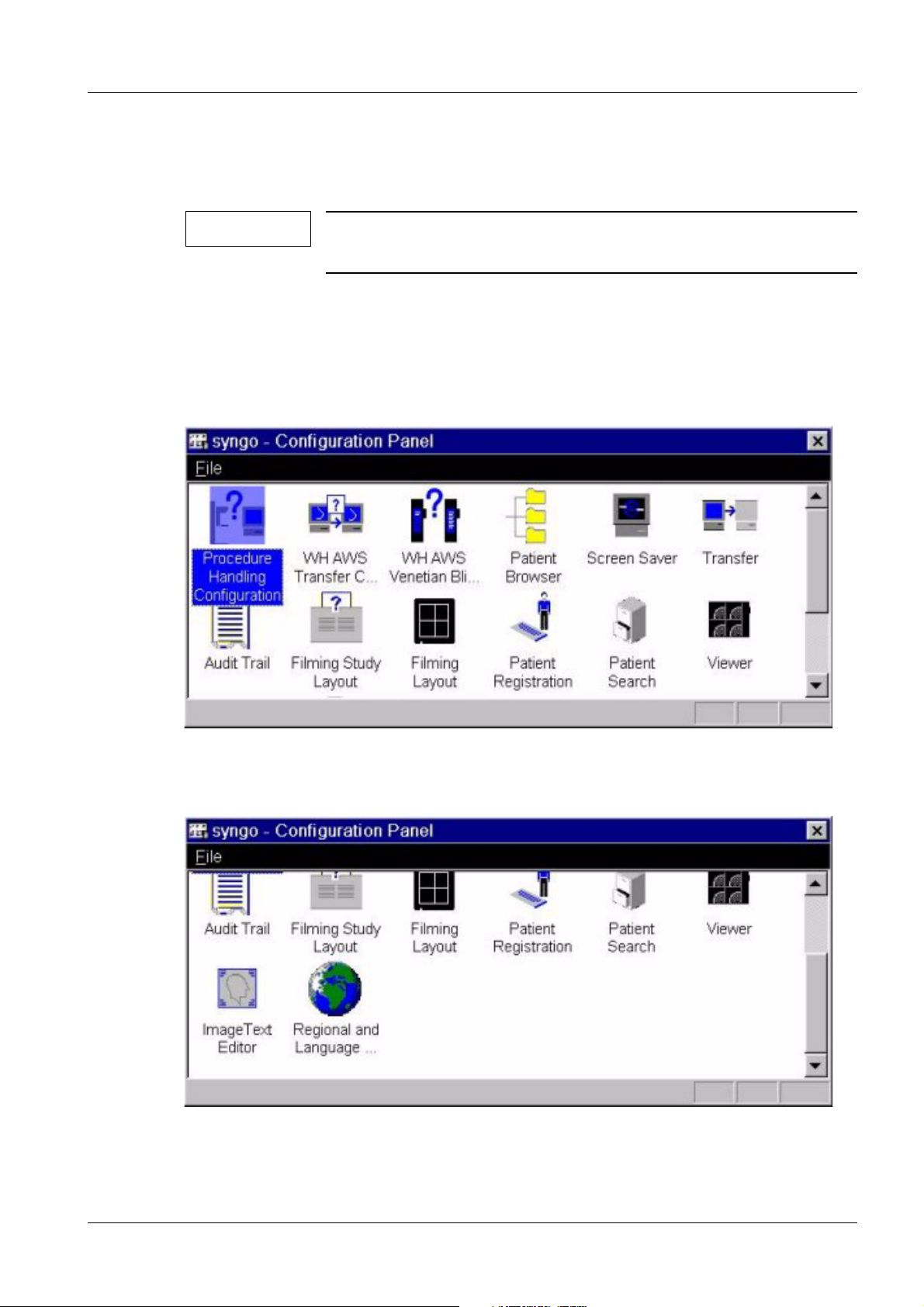
• Select Options > Configuration from the user software interface.
¹ The following window is displayed.
Fig. 1: Configuration panel 1
• Scroll down the window.
Fig. 2: Configuration panel 2
• Double-click Regional and Language Options.
Siemens AG SPB7-250.815.02.03.02 MAMMOMAT Novation DR
Medical Solutions
08.05 CS SD 24
Page 23 of 80
Page 24
24 Configuration
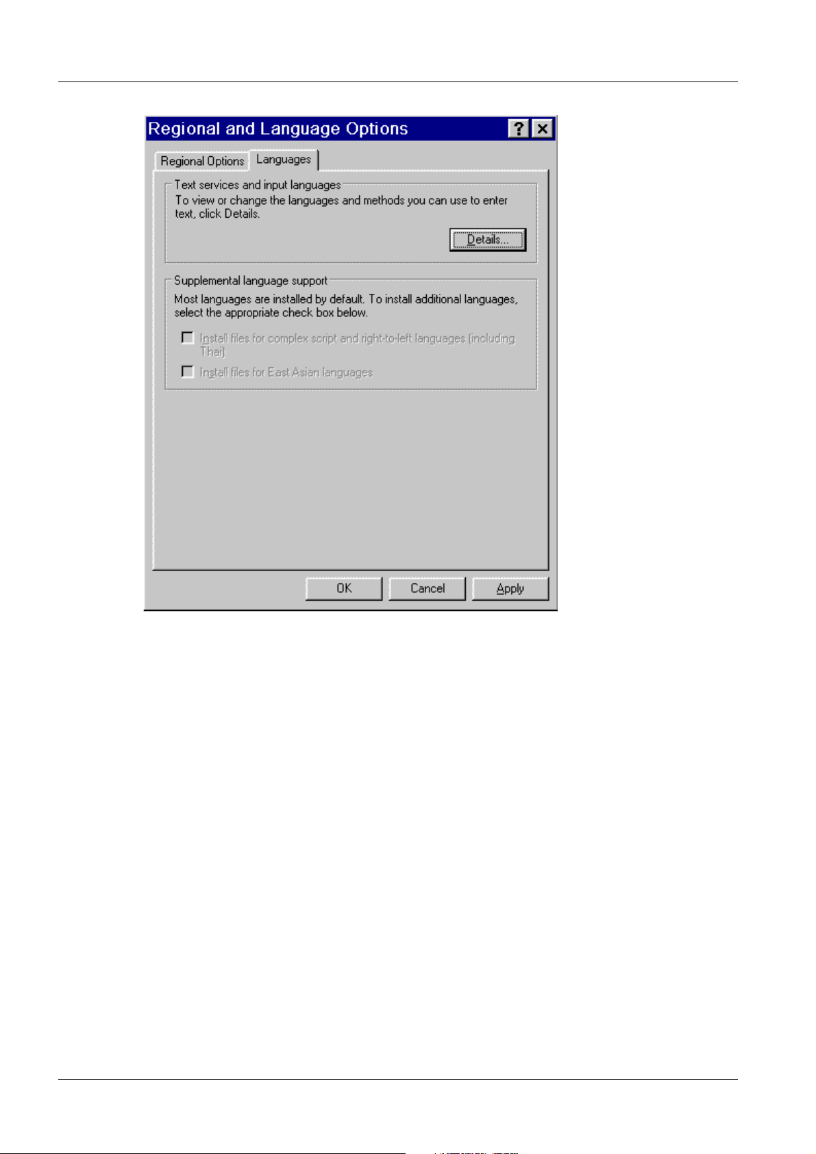
Fig. 3: Languages
• Select Language tab.
• Click on Details.
MAMMOMAT Novation DR SPB7-250.815.02.03.02 Siemens AG
08.05 CS SD 24
Page 24 of 80
Medical Solutions
Page 25

Configuration 25
Fig. 4: Language Settings
• Select the language (only English, Spanish, German and French are supported) under
Default input language or use the Add button to install your language.
Siemens AG SPB7-250.815.02.03.02 MAMMOMAT Novation DR
Medical Solutions
08.05 CS SD 24
Page 25 of 80
Page 26

26 Configuration
Fig. 5: Input Language
• Select one of the installed input languages and keyboard layout.
• Click on OK.
• Confirm with Apply.
• Click on OK.
• Confirm with Apply.
• Click on OK.
• Close the Configuration Panel.
Preferred User Interface Language (not required for English) 0
• Select Options < Configuration from the Viewer interface.
The following window appears.
MAMMOMAT Novation DR SPB7-250.815.02.03.02 Siemens AG
08.05 CS SD 24
Page 26 of 80
Medical Solutions
Page 27

Configuration 27
Fig. 6: Configuration panel 1
• Scroll down the window.
Fig. 7: Configuration panel 2
• Double-click Regional and Language Options.
Siemens AG SPB7-250.815.02.03.02 MAMMOMAT Novation DR
Medical Solutions
08.05 CS SD 24
Page 27 of 80
Page 28

28 Configuration
Fig. 8: Regional Options
• Select Regional Options tab.
• Select the language (only English, Spanish, German and French are supported), and
location.
MAMMOMAT Novation DR SPB7-250.815.02.03.02 Siemens AG
08.05 CS SD 24
Page 28 of 80
Medical Solutions
Page 29

Configuration 29
Fig. 9: Selecting Regional Options
• Click on Apply.
• Click on OK.
• Close the Configuration Panel.
Siemens AG SPB7-250.815.02.03.02 MAMMOMAT Novation DR
Medical Solutions
08.05 CS SD 24
Page 29 of 80
Page 30

30 Configuration
syngo configuration 0
This chapter describes how to configure the WH AWS within the syngo service software.
Log into the service software.
• Select Options > Service -> Local Service in the window menu header
Fig. 10: Authentication Page
• Enter the service key (6 characters in 2nd field) in the syngo software screen.
• Select Set as Default.
• Confirm the screen with OK.
¹ The Service Home Menu then appears.
MAMMOMAT Novation DR SPB7-250.815.02.03.02 Siemens AG
08.05 CS SD 24
Page 30 of 80
Medical Solutions
Page 31

Configuration 31
Fig. 11: Service Home Menu
• Select Configuration.
¹ The Configuration selection menu appears. It shows the default settings that
should be used for the MAMMOMAT Novation DR.
Siemens AG SPB7-250.815.02.03.02 MAMMOMAT Novation DR
Medical Solutions
08.05 CS SD 24
Page 31 of 80
Page 32

32 Configuration
Fig. 12: Configuration - System Options
Connected to Network The system is connected to a network
Modem Modem RAS, not used for the WH AWS. Do not select.
Main Console with Satellite or Satellite Console
DICOM Print Devices DICOM Basic Print service for laser cameras
DICOM Offline Devices DICOM Media Storage on off-line media like MOD and CD-R
DICOM Networking DICOM services to DICOM PACS systems
DICOM HIS/RIS DICOM Hospital Information System/Radiology Information
Image Import/Export Import/export DICOM images from/to the file system
Paper Printer Paper formats for postscript printers
EPRI Electronic Patient Record Interface, if available
System Management Siemens System Management funtionality
SNMP Simple Network Managed Protocol
Enabling Help Pages This enables/disables the guided help pages. Experienced
The MAMMOMAT Novation DR does not use a Satellite Console. Do not select.
system
users may disable them.
• Select the check boxes according to your environment.
¹ The (Fig. 12 / p. 32) shows the default settings that should be used for the MAM-
MOMAT Novation DR.
• Select Next in the action bar.
MAMMOMAT Novation DR SPB7-250.815.02.03.02 Siemens AG
08.05 CS SD 24
Page 32 of 80
Medical Solutions
Page 33

Configuration 33
NOTICE
To exit the configuration, ALWAYS select the "Finish" and then the
"Home" buttons.
¹ Otherwise the entered data are lost.
• Select “Site Info” within the configuration menu and enter at least the data for:
- System serial number
- handover date
- customer data
• Click “Save”.
Fig. 13: Site_Info
• Select “TCP/ IP” within the configuration menu and enter the data for:
- TCP IP address (only one IP addresses is allowed).
- Subnet mask.
- Gateway address (only one IP addresses is allowed).
- Optional settings, DNS, WIN, DHCP (permanent IP address).
Siemens AG SPB7-250.815.02.03.02 MAMMOMAT Novation DR
Medical Solutions
08.05 CS SD 24
Page 33 of 80
Page 34

34 Configuration
• Click “Save”
Fig. 14: TCP_IP
• Select “DICOM/ General” within the configuration menu and check or edit the data for
local AE titles of the WH AWS.
• Click “Save”.
Fig. 15: Local AET
• Select “DICOM/ Offline Devices” within the configuration menu and configure CD
drives if applicable. (For more information click “Help” within the menu).
• Click “Save”.
• Select “DICOM/ Network Nodes” within the configuration menu to configure network
nodes, e.g. workstation, archive systems.
MAMMOMAT Novation DR SPB7-250.815.02.03.02 Siemens AG
08.05 CS SD 24
Page 34 of 80
Medical Solutions
Page 35

Configuration 35
• Enter the data for each network node to be configured and click “Save”
-Host Name.
- IP Address of the network node.
Fig. 16: Network_nodes_host
• Click “>”
Siemens AG SPB7-250.815.02.03.02 MAMMOMAT Novation DR
Medical Solutions
08.05 CS SD 24
Page 35 of 80
Page 36

36 Configuration
• Enter the data for each network node to be configured and click “Save”. For more infor-
mation, see the section “Hints/ Notes” in this documentation.
- AE Title of the network node.
- Port of the network node.
- Select services of the network node, e.g. Storage, Storage Commitment, Query, Retrieve.
Fig. 17: Network_nodes_general
• Select “DICOM/ Print Devices” within the configuration menu. For configuration, refer
to the section “Configuration of DICOM Camera” in this documentation and enter the required data.
• Select “DICOM/ HIS/ RIS Node” within the configuration menu for configuring the “DI-
COM worklist” if applicable.
MAMMOMAT Novation DR SPB7-250.815.02.03.02 Siemens AG
08.05 CS SD 24
Page 36 of 80
Medical Solutions
Page 37

Configuration 37
• Enter the data for the DICOM worklist server and click “Save”
-Host Name.
- IP Address of the server.
Fig. 18: HIS_RIS host
• Click “>”
• Enter the data for the DICOM worklist services.
For more information, see the section “Hints/ Notes” in this documentation.
Siemens AG SPB7-250.815.02.03.02 MAMMOMAT Novation DR
Medical Solutions
08.05 CS SD 24
Page 37 of 80
Page 38

38 Configuration
- AE Title of the worklist server.
- Port of the worklist server
- Select “Basic Worklist”
- Additional services of the network node, e.g. “Performed Procedure Step” if applicable.
Fig. 19: Worklist
• Click “Save”
MAMMOMAT Novation DR SPB7-250.815.02.03.02 Siemens AG
08.05 CS SD 24
Page 38 of 80
Medical Solutions
Page 39

Configuration 39
Finishing and checking the configuration 0
• After configuration of the WH AWS click “Home” and confirm the message to reboot the
system with “OK”.
¹ The WH AWS will reboot.
• Connect the WH AWS the to the hospital network.
• Check the connectivity to each configured network node within the local service/ config-
uration/ DICOM menu (network nodes or DICOM Print Devices) by using “Verification."
¹ If the connectivity test fails, check the configured data on the WH AWS and on
the destination node.
¹ Try a ping command “local service/ Utilities/ Escape to OS” to the destination
node.
¹ Try the DICOM test tools
Siemens AG SPB7-250.815.02.03.02 MAMMOMAT Novation DR
Medical Solutions
08.05 CS SD 24
Page 39 of 80
Page 40

40 Configuration
Options configuration 0
Installation of a paper printer 0
1. Log in as Windows XP Administrator
2. Click on Start, select Properties, and then Printers
Fig. 20: Configuring a Paper Printer - Add a new Printer
Fig. 21: Printer Wizard
When using a USB printer, the computer will recognize the printer via plug & play.
In that case you can follow the computer's instructions.
MAMMOMAT Novation DR SPB7-250.815.02.03.02 Siemens AG
08.05 CS SD 24
Page 40 of 80
Medical Solutions
Page 41

Configuration 41
If problems occurred with the driver or you are using a parallel port printer or network
printer, continue with the following instructions.
Local printer
Fig. 22: Printer Wizard - Local Printer
Select Local printer and select the corresponding port of that printer.
Fig. 23: Printer Wizard - Select a local port (USB or parallel port)
Siemens AG SPB7-250.815.02.03.02 MAMMOMAT Novation DR
Medical Solutions
08.05 CS SD 24
Page 41 of 80
Page 42

42 Configuration
Fig. 24: Printer Wizard - new port = USB
Fig. 25: Printer Wizard - select a local printer
Select the correct manufacturer and the model of the customer's printer.
MAMMOMAT Novation DR SPB7-250.815.02.03.02 Siemens AG
08.05 CS SD 24
Page 42 of 80
Medical Solutions
Page 43

Configuration 43
Fig. 26: Printer Wizard - name the printer
Assign the printer a name (usually the model name of the printer).
Fig. 27: Printer Wizard - do not share a local printer
Siemens AG SPB7-250.815.02.03.02 MAMMOMAT Novation DR
Medical Solutions
08.05 CS SD 24
Page 43 of 80
Page 44

44 Configuration
Fig. 28: Printer Wizard - print a test page
Fig. 29: Printer Wizard - finish and close the wizard
MAMMOMAT Novation DR SPB7-250.815.02.03.02 Siemens AG
08.05 CS SD 24
Page 44 of 80
Medical Solutions
Page 45

Configuration 45
Fig. 30: Printer Wizard - check the result (test page)
Generate a test page to make sure that the printer is functioning properly.
Network printer
1. Log in as Windows XP Administrator
2. Click Start, select Properties, and then Printers
Fig. 31: Printer Wizard - network printer
Siemens AG SPB7-250.815.02.03.02 MAMMOMAT Novation DR
Medical Solutions
08.05 CS SD 24
Page 45 of 80
Page 46

46 Configuration
Fig. 32: Printer Wizard - Example of a network printer
Fig. 33: Printer Wizard - use as default printer ?
MAMMOMAT Novation DR SPB7-250.815.02.03.02 Siemens AG
08.05 CS SD 24
Page 46 of 80
Medical Solutions
Page 47

Configuration 47
Fig. 34: Printer Wizard - finish and close the wizard
Siemens AG SPB7-250.815.02.03.02 MAMMOMAT Novation DR
Medical Solutions
08.05 CS SD 24
Page 47 of 80
Page 48

48 Configuration for DICOM Camera
5Configuration for DICOM Camera
6-
General 0
DICOM Print Device 0
A DICOM Print Device is a hardcopy camera (also called DICOM camera or DICOM
printer) that supports DICOM Basic Print. The expression "DICOM camera" is used in this
document.
Additionally Required Documents 0
The validity of the DICOM Camera connection depends on the modality and/or application.
The document Installation and Startup Camera (SPB7-250.814.20.xx.xx) is required.
The document contains the list of released DICOM cameras, specific information on this
modality, e.g., LUT’s and image quality in conjunction with DICOM cameras. It also contains DICOM camera data on the type and special modality settings, if required.
The document is required, in particular to avoid data mismatching and/or loss of image
quality. For this reason, some values are marked with the warning: "Do not change,
unless otherwise noted." In this case, refer to the modality/application document.
MAMMOMAT Novation DR SPB7-250.815.02.03.02 Siemens AG
08.05 CS SD 24
Page 48 of 80
Medical Solutions
Page 49

Configuration for DICOM Camera 49
Configuration for DICOM Print devices 0
This chapter describes how to configure a new DICOM camera into the syngo configuration.
Enter the configuration data for each DICOM camera separately, if applicable.
Refer first to the section “Collecting configuration data.” For additional information within
the configuration menu, please click the “Help” button in the configuration mask.
• Log into “Local Service”.
• Select “Configuration” within the menu.
• Select “DICOM/ Print Devices”.
• Click “Next”.
¹ The “Host Properties” menu will appear.
TCP/IP Settings for the DICOM Camera 0
Host Properties of the DICOM camera
• Click on the "Select Host" drop-down menu, select “define new” and enter the host
name of the DICOM camera in the field “Host Name”.
• Enter the TCP/IP address of the DICOM camera.
• Select “LAN”.
Fig. 35: Print_devices_host
• Click “Save” to save the data.
• Click on "OK" and then ">".
Siemens AG SPB7-250.815.02.03.02 MAMMOMAT Novation DR
Medical Solutions
08.05 CS SD 24
Page 49 of 80
Page 50

50 Configuration for DICOM Camera
General node properties of the DICOM camera 0
• Enter the “Logical Name” of the DICOM camera in the field “edit Name”.
¹ The logical name is used as an identification within the DICOM Printer menu.
• Select “Host” and choose the previously defined host name for the DICOM Print De-
vice (Host Properties).
• Click “Save”.
Fig. 36: Print_devices_properties
Application entity properties 0
• Enter the AE Title of the DICOM camera in the field “edit AE Title”.
• Enter the port number of the DICOM camera in the “Port” field.
• Click “ADD”.
NOTE
If you select an AET that is already configured, the Add button will
change to the Del button, allowing you to delete this AET, if required.
• Select the created AE Title of the DICOM camera from the “AE Title” field.
Supported DICOM services 0
• Check the box “Print”.
• Click on "Save".
¹ DICOM node properties successfully saved.
• Click "OK" and then ">"
MAMMOMAT Novation DR SPB7-250.815.02.03.02 Siemens AG
08.05 CS SD 24
Page 50 of 80
Medical Solutions
Page 51

Configuration for DICOM Camera 51
Camera parameter settings 0
• Select the DICOM camera in the pull-down menu “Select HC device”.
• Enter the name of the DICOM camera in the “HC Device” field, which will be displayed
in the customer user interface on the Print tab card.
• When the check box “Default Camera” is selected, the DICOM camera will be set as
the default camera. The other DICOM cameras need to be selected from a pull-down
menu on the Print tab card on the customer user interface.
Fig. 37: Print_devices_general
General settings 0
The general setting for each DICOM camera is described in "Specific Hardcopy Camera
Information" (see Overview, Additionally Required Documents)
• Select “DICOM Printer” in the “Type” field for the DICOM camera.
¹ SPCI printers are not supported.
• Select the pull-down menu from “Class”. Select your DICOM camera type. A specific
file for this type will be loaded, and the “Filming Properties” (see below) will be displayed.
• In the field “DICOM Node” the logical names of the DICOM cameras defined previously
are shown. Select the appropriate DICOM camera.
• Enter the location of the DICOM camera. The information will be displayed in this con-
figuration menu only.
• Enter comments, such as the help desk phone number of the DICOM camera vendor.
The information will be displayed in this configuration menu only.
Siemens AG SPB7-250.815.02.03.02 MAMMOMAT Novation DR
Medical Solutions
08.05 CS SD 24
Page 51 of 80
Page 52

52 Configuration for DICOM Camera
Filming properties 0
The displayed settings depend on the selected class (DICOM camera). See also Overview, Additionally Required Documents
Hold printed film jobs
• The most recent film jobs remain in the print queue, even after a film has been success-
fully printed. The number of films in the queue is defined here. Default setting = 10;
max. = 10
Min. Density [1/100 O.D.]
• Set the minimum density value for the film used, default setting = 20; this value can be
changed in increments/decrements of 1 (the maximum density value is modality-dependent and is set in the ’LUT files’ menu).
Pixel Size [1/1000 mm]
• This is the pixel dot size specified for this DICOM camera. Do not change, unless other-
wise noted.
Portrait / landscape film sheet formats
• All formats (media sheet sizes and orientation) specified for this DICOM camera are
provided in these fields. Select film sizes and delete only those not available on site. Do
not change (modify and/or add film sizes), unless otherwise noted.
Number of pixels [rows, columns]
• The number of pixels (rows and columns) specified for this DICOM camera are provid-
ed in this field. Do not change (modify number of pixels), unless otherwise noted.
Medium type
• The possible medium types are provided in this field: blue film; clear film; paper; default
setting = blue film
Film destination
• The possible film destination ’magazine’ or ’processor’ is provided in this field. Select
the film destination as specified by the local camera service; default setting = processor.
MAMMOMAT Novation DR SPB7-250.815.02.03.02 Siemens AG
08.05 CS SD 24
Page 52 of 80
Medical Solutions
Page 53

Configuration for DICOM Camera 53
Color appearance
• The possible color appearance, ’Grayscale 8 bit’; ’Grayscale 12 bit’ or ’Color 24 bit’ is
provided in this field. Default setting = Grayscale 12 bit. Do not change.
Color 24 bit:
¹ In this case, the camera negotiates the "Basic Color Print Management" and
transfers the pixel data in RGB photometric interpretation.
8 bit gray scale:
¹ In this case, the camera will negotiate the "basic grayscale print management"
and transfer the pixel data in photometric interpretation MONOCHROME2 with 8
bit pixel depth
12 bit gray scale:
¹ In this case, the camera negotiates the "basic grayscale print management" and
transfers the pixel data in photometric interpretation MONOCHROME2 with a
12-bit pixel depth (16 bits allocated for each pixel, e.g. for mammography
images).
Background
• The background of the film can be set to ’black’ or ’white’; default setting = black.
Transformation
Normally no transformation; in special cases, an additional transformation is required in
the DICOM camera. The following values are possible:
• Replicate: the interpolated value is identical to the last pixel value
• Bilinear: the interpolated value is between (linear) the last pixel value and the next pixel
value
• Cubic: the interpolated value is between (curve) the last pixel value and the next pixel
value
• No magnification: leaves the image as is; default setting = no magnification. Do not
change, unless otherwise noted.
• Click on "Save"
• Caution: Please wait for the message "device properties successfully saved."
• Click on "OK"; “Finish.”
NOTICE
Deleting print devices
If a DICOM camera is to be deleted from the configuration settings,
start the deletion with the last menu of the print device setup and
go back to first menu. Otherwise, the error message "Option value
warning: Invalid node could not be found" will be displayed.
¹ To enter a new DICOM camera, always start with the first
menu of the setup.
Siemens AG SPB7-250.815.02.03.02 MAMMOMAT Novation DR
Medical Solutions
08.05 CS SD 24
Page 53 of 80
Page 54

54 Configuration for DICOM Camera
LUT Files 0
This menu allows you to import, remove, and select LUT files (Look Up Table) for DICOM
Basic Print. No tool is available for modifying a lookup table (LUT editor).
NOTE
LUT Settings
The following are the default settings for Correction LUT.
The important setting for Mammography is the DXMGImage setting.
The Presentation LUT has not been released for use.
GSDF will be supported for printing (Presentation LUT) only, but
currently not for the monitor.
• Select “DICOM/ LUT” within the configuration menu.
Fig. 38: LUT
• Click “Next”.
• Mark the check box “Correction LUT”.
• Enter the values as shown in the figure below.
MAMMOMAT Novation DR SPB7-250.815.02.03.02 Siemens AG
08.05 CS SD 24
Page 54 of 80
Medical Solutions
Page 55

Configuration for DICOM Camera 55
Fig. 39: LUT_table
Explanation of LUT
Correction LUT / Presentation LUT
• For an explanation, see Menu options (above). Special settings depend on the modali-
ty (see Overview, Additionally Required Documents) (Note: "Presentation LUT" and
"Correction LUT" are logical names and do not correspond to each other in the different
options; i.e., both presentation LUT’s in the 2nd and 3rd options can have the same
name but different contents).
• There may be 8-bit LUT’s and 16-bit LUT’s in the LUT selection box. This does not
mean that one kind of LUT is made for 8-bit images and another for 16-bit images. This
means that the 8-bit LUT’s have only 256 values to describe the LUT. The 16-bit LUT
has 65 KB and is therefore much more precise. The disadvantage of a 16-bit LUT is that
it is quite large. For a correction LUT (camera is linear), the LUT is used only for the
camera, NOT for the monitor. For a presentation LUT (camera and monitor are adjusted according to the Barten curve), the LUT is used for the camera and for the monitor.
Siemens AG SPB7-250.815.02.03.02 MAMMOMAT Novation DR
Medical Solutions
08.05 CS SD 24
Page 55 of 80
Page 56

56 Configuration for DICOM Camera
Max. density
• This value is required for each LUT and is imported together with the LUT (do not
change this default value, unless otherwise noted). This value will be used together with
’Overall maximum density’ to scale the image presentation for each image per film
sheet (Hint: the Min. Density value will be set once in the ’Print device menu’).
Overall maximum density
• This value will be used to set the maximum required density on the film. Default setting
= 3.00. (The overall maximum density value has to be equal to or higher than the "Max.
density entries" for the different image types).
Interpolation for printing
• The complete film sheet is calculated in the modality and then sent to the DICOM cam-
era (page mode). To fit the images onto this virtual film sheet, pixel interpolation is required. Do not change, unless otherwise noted.
The following values are possible:
Replicate: the interpolated value is identical to the last pixel value
Bilinear: the interpolated value is between (linear) the last pixel value and the next
pixel value
Cubic: the interpolated value is between (curve) the last pixel value and the next pixel
value
Mode
• The smoothing type factor can be selected for the cubic interpolation algorithm only
(smoothing factors are 0, 2, 3, 4). Do not change, unless otherwise noted.
• Click on "Save" after making the changes.
• Click on "Finish."
• Click on "Home"; the system restarts automatically.
NOTE
If the message "restart syngo pending" appears in the bottom status line, an application
restart is automatic after the "HOME" button is pressed.
If the message "shutdown syngo pending" appears in the bottom status line, a system
restart is automatic after the "HOME" button is pressed.
This may take some time.
Confirm the warnings with "OK."
MAMMOMAT Novation DR SPB7-250.815.02.03.02 Siemens AG
08.05 CS SD 24
Page 56 of 80
Medical Solutions
Page 57

Siemens Remote Service 57
6Siemens Remote Servic e
7-
Siemens Remote Service 0
General information 0
Since MAMMOMAT Novation DR WH AWS VA11A is syngo based, the WH AWS shall be
connected to “Siemens Remote Service.”
The "SIEMENS Remote Services" will support router or VPN connections only.
A VPN should be used via a broadband connection.
The project manager is responsible for implementing a router connection to the Siemens
Remote Diagnostic server. If you have any questions about your pre-configured router
from Siemens, please contact mailto:srs_final@med.siemens.de or your remote diagnostic technician. A detailed description of the SRS installation is available in the ’Software,
SP00-000.816.02.02.02’ manual.
Procedure 0
The WH AWS must be connected to an ISDN router, analog router, or VPN in order to be
able to access Siemens Remote Service. Configure the WH AWS as described below:
For a detailed description, see the document “Installation of Siemens Remote Service,
SP00-000.816.02...," section on "SRS Configuration”.
• Enable remote access, “Limited Access, permanent” within the user interface “Option/
Service/ Remote Service.”
• Enter the local service/ “Configuration.”
Siemens AG SPB7-250.815.02.03.02 MAMMOMAT Novation DR
Medical Solutions
08.05 CS SD 24
Page 57 of 80
Page 58

58 Siemens Remote Service
• Select “Service/ FTP” and enter the FTP Host and IP address according to your time
zone:
Global zone Server
location
Time zone I (Europe,
Africa)
Time zone II (America) Newark Name: SRSACC1 / IP: 129.73.116.92
Time zone III (Asia, Australia)
Fürth Name: LUX09505 / IP: 194.138.39.18
Singapore Name: SGPT806x / IP: 194.138.243.178
Siemens Remote Access Server
Fig. 40: FTP_Host
• Click “Save” and then “>”
• Enter SRS_FTP in the “Logical Name” field.
• From the selection bar, select the FTP Host you created.
• Enter rdiagftp in the FTP user field.
MAMMOMAT Novation DR SPB7-250.815.02.03.02 Siemens AG
08.05 CS SD 24
Page 58 of 80
Medical Solutions
Page 59

Siemens Remote Service 59
• Enter the password siemens twice.
Fig. 41: FTP_user
• Click “Save."
• Check routing (static route or routing over a gateway) from the WH AWS to the Sie-
mens Remote Access Server.
¹ WH AWS and the router (ISDN or analog) or VPN in the same subnet:
Configure a static route: local service/ Utilities/ Escape to OS:
> route add -p “SRS environment” mask 255.255.255.0 “router IP address”
e.g.fürth and ISDN router 192.168.237.254:
>route add -p 194.138.39.0 mask 255.255.255.0 192.168.237.254
¹ WH AWS and the router (ISDN or analog) or VPN not in the same subnet:
Enter the gateway IP address as described in the “Configuration” section of this
documentation.
The local administrator will configure the gateway for routing.
Run a connectivity test to the Siemens Remote environment.
• From the Service Software Home Menu, select Utilities -> Escape to OS
• Under Command, select NT Command Interpreter
• Within the NT Command Interpreter under Parameters, enter one of the following com-
mands and execute it by pressing <CR> or clicking <GO>. The tracert program takes a
while before the data is displayed. When the mouse is moved into the frame, the hourglass indicates that the program is executing.
tracert 194.138.39.22 Command executing from time zone I
tracert 129.73.116.94 Command executing from time zone II
tracert 194.138.243.178 Command executing from time zone II
Siemens AG SPB7-250.815.02.03.02 MAMMOMAT Novation DR
Medical Solutions
08.05 CS SD 24
Page 59 of 80
Page 60

60 Siemens Remote Service
System management 0
General information 0
The System Management functionalities are available (CA Unicenter) for the MAMMOMAT Novation from version VA11B onward (Syngo Version VD20 - Windows XP).
The MAMMOMAT Novation DR software contains the “Manage Node Package” for System Management. Configuration of System Management is therefore recommended.
CA Unicenter provides a software distribution function that enables the system software to
be updated remotely; e.g., a virus pattern update.
In the future the System Management software will monitor the system performance for
continuity.
The CA Unicenter servers are located within the SRS environment in Fürth and in Newark. SP systems connected to Singapore use the CA environment in Newark (see note
"for sites within time zone III only").
Global zone Server
location
Time zone I (Europe,
Africa)
Time zone II (America) Newark Name: SRSSQL03 / IP: 129.73.116.94
Time zone III (Asia, Australia)
(*) ...No System Management Server is available in Singapore, systems in this zone
report to Newark.
Fürth Name: fthw9mva / IP: 194.138.39.22
Newark Name: SRSSQL03 / IP: 129.73.116.94
CA Unicenter
Prerequisite 0
The SRS connectivity from the modality to the Siemens Remote environment of your time
zone is available and tested. (refer to the document "Installation of SRS,
SP00-000.816.02…”).
Particularly a wide band connection via VPN should be used.
For sites within time zone III only (Asia, Australia)
Ignore this section if the SRS router is entered on the SP system as the default gateway
under the TCP/ IP settings.
If a static route is used from the SP system to access the SRS environment, then 2 static
routes have to be entered as described in the document “Installation of SRS,
SP00-000.816.02..., Chapter Configuration”. You can check the entry by entering command route print -p in the command interpreter (Escape to OS).
MAMMOMAT Novation DR SPB7-250.815.02.03.02 Siemens AG
08.05 CS SD 24
Page 60 of 80
Medical Solutions
Page 61

Siemens Remote Service 61
For SRS in Singapore route add -p 194.138.243.0 mask 255.255.255.0
<IP_SRS_router>
For System Management
Server, Newark
route add -p 129.73.116.0 mask 255.255.255.0
<IP_SRS_router>
Procedure 0
Before setting up the System Management functionalities the Siemens Remote environment must be reachable.
Connectivity Check
• From the Service Software Home Menu, select Utilities -> Escape to OS
• Under Command, select NT Command Interpreter
• Within the NT Command Interpreter under Parameters, enter one of the following com-
mand and execute it by pressing <CR> or clicking <GO>. The tracert program takes a
while before the data is displayed. When moving the mouse into the frame, the hourglass indicates that the program is executing
tracert 194.138.39.22 Command executing from time zone I
tracert 129.73.116.94 Command executing from time zones II, III
NOTE
Installation procedure
To establish the connection may need some time. As a result, the
tracert program may time out. Repeat the tracert command and
check the function again. Do not continue with the installation if
the connectivity test fails.
• Select Local Service --> Configuration,
Siemens AG SPB7-250.815.02.03.02 MAMMOMAT Novation DR
Medical Solutions
08.05 CS SD 24
Page 61 of 80
Page 62

62 Siemens Remote Service
• In the next window enable System Management in the option list and click <Next>
twice.
Fig. 42: SM_enable
MAMMOMAT Novation DR SPB7-250.815.02.03.02 Siemens AG
08.05 CS SD 24
Page 62 of 80
Medical Solutions
Page 63

Siemens Remote Service 63
• Enter Server Name and IP address of your System Management server of your zone
Global zone server
location
Time zone I (Europe,
Africa)
Time zone II (America) Newark Name: SRSSQL03 / IP: 129.73.116.94
Time zone III (Asia, Australia)
(*) ...No System Management Server is available in Singapore, systems in this zone
report to Newark.
Fürth Name: fthw9mva / IP: 194.138.39.22
Newark Name: SRSSQL03 / IP: 129.73.116.94
CA Unicenter
Fig. 43: SM_config
• If NAT (Network Address Translation) is used, enter the appropriate network address. If
you are not sure, ask the SRS Help Desk.
NOTE
The SRS database can handle only unique IP addresses for modalities. For modalities in the field with identical IP addresses a pseudo IP address from the SRS Help desk will be created and handled
with the NAT (Network Address Translation) tool.
• Click “Next”
Siemens AG SPB7-250.815.02.03.02 MAMMOMAT Novation DR
Medical Solutions
08.05 CS SD 24
Page 63 of 80
Page 64

64 Siemens Remote Service
• Check all boxes as shown and click on “GO”
¹ The System Management registration and installation of templates starts. This
takes approximately 15 minutes.
Fig. 44: SM_install
• After the installation is successfully completed, close the configuration menu and re-
boot the system.
Troubleshooting 0
If the installation of System Management fails, the “Siemens Remote Access Server” or
the “Software Distribution Server” are probably not reachable from your node.
Please check the following points:
• Reboot the system and try once again to configure the System Management.
• Make sure that the Siemens Remote environment is reachable. Do a tracert command
as described in the “Connectivity Check” paragraph in this section.
• Check whether your system needs a static route or whether it routes over a gateway in
the hospital. (refer to the document "Installation of SRS, SP00-000.816.02…”).
• Contact the SRS help desk for support.
MAMMOMAT Novation DR SPB7-250.815.02.03.02 Siemens AG
08.05 CS SD 24
Page 64 of 80
Medical Solutions
Page 65

Final work steps 65
7Final work steps
8-
Backup data 0
A backup of system-specific data, such as customer configuration entries, security settings, network nodes and AETs is always necessary after software updates or system
adjustments.
NOTE
Backup comprises:
- syngo configuration ("Configuration" under "Local Service")
- User Settings ("Options" -> "Configuration")
- Application Licenses (license.dat)
- Detector-specific files
- Security Settings
Database (patient images) backup is not possible. You can only
save the patient images to a MOD, CD-R or an archiving system.
• From the syngo user interface, select Options -> Service -> Local Service in the Win-
dow menu.
• Enter the service key (6 characters in 2nd field).
• Confirm with OK.
¹ The Service Home menu appears.
• Select Backup & Restore.
• Insert the BACKUP disk either into floppy drive or the CD-RW.
¹ The Backup/ Restore menu window appears:
• In the Command selection menu, select Backup.
• For Drives, select the particular storage medium. As a standard, save to a diskette (-A-)
or CD-RW (-R-). Network devices are supported as well.
• Select the DXMG Mammomat package and save via GO.
• Wait until the "Ready" message appears in the footer.
• Select the Security settings package and save via GO.
• Wait until the "Ready" message appears in the footer.
• Select the SW Settings02 package and save via GO.
• Wait until the "Ready" message appears in the footer.
• Select the WH_AWS_backup_restore package and save via GO.
• Wait again until the "Ready" message appears in the footer.
• Exit the window with Home.
• Remove the backup medium either from drive A: or R: and archive it.
Siemens AG SPB7-250.815.02.03.02 MAMMOMAT Novation DR
Medical Solutions
08.05 CS SD 24
Page 65 of 80
Page 66

66 Final work steps
NOTICE
If subsequent changes (e.g. in the configuration) are made, the
corresponding backup package must be saved again.
¹ All dynamic data changes must be stored via this syngo
BACKUP.
MAMMOMAT Novation DR SPB7-250.815.02.03.02 Siemens AG
08.05 CS SD 24
Page 66 of 80
Medical Solutions
Page 67

Hints / Notes 67
8Hints / Notes
9-
Network Adapter Settings 0
General 0
Due to the many different types of network switch available and the different network
adapters provided with the syngo hardware, the general default "Auto detect" configuration of the network switches and adapters doesn’t work reliably and its use results in poor
network performance.
Therefore, the recommended procedure is to configure the the syngo hardware's network
adapter to a specific speed (Link Speed & Duplex) to avoid auto negotiation (e.g.
100Mbps/Full duplex).
This must be done on both sides of the syngo network adapter as well as on-site, at the
corresponding network switch, for the existing network installation that is directly connected to it. It is therefore very important to consult the network administrator, since he or
she is responsible for configuring the particular switch accordingly.
The link speed to be configured depends on the proposed transfer performance and on
the recommended speed of the modality or syngo product. Please refer to the product's
other start-up instructions, pertinent Speedinfos, or support center bulletins.
We assume that our network card's settings will be configured automatically by the "auto
detect mechanism" between the card and the switch.
This mechanism often does not work!! The network switch is frequently not set to "auto
detect," which may cause problems if our card is set to "auto detect".
The administrator password is therefore required. The customer's network administrator
needs to be involved in the process.
Configuration 0
To change the network adapter settings, it is necessary to log into the operating system
(Windows XP) as "Administrator".
Click the "Start" button, click Settings, and then Network Connections.
Siemens AG SPB7-250.815.02.03.02 MAMMOMAT Novation DR
Medical Solutions
08.05 CS SD 24
Page 67 of 80
Page 68

68 Hints / Notes
Fig. 45: Start -> Settings -> Network Connections
Fig. 46: Network Connection -> Properties
MAMMOMAT Novation DR SPB7-250.815.02.03.02 Siemens AG
08.05 CS SD 24
Page 68 of 80
Medical Solutions
Page 69

Hints / Notes 69
Within the Network Connection window please select the LOCAL Area Connection icon
with the right mouse button, then select Properties
Fig. 47: Client Properties
Siemens AG SPB7-250.815.02.03.02 MAMMOMAT Novation DR
Medical Solutions
08.05 CS SD 24
Page 69 of 80
Page 70

70 Hints / Notes
Fig. 48: Network adapter configuration - Link Speed & Duplex
In the Local Area Connection Properties window, click the Configure button below the
name of the adapter model. This opens the network adapter properties configuration window.
Under the Advanced tab, find the "Link Speed" item in the Property box. In the Value
selection box, select the proper speed. A system reboot may be required.
(This description applies to Windows XP as a platform for syngo VD20H and higher.)
CAUTION
It is absolutely necessary for the corresponding port of the network switch to be configured to the same speed and duplex mode
selected in the card's configuration.
¹ Otherwise it will not be possible to establish a network
connection.
MAMMOMAT Novation DR SPB7-250.815.02.03.02 Siemens AG
08.05 CS SD 24
Page 70 of 80
Medical Solutions
Page 71

Hints / Notes 71
DICOM connectivity test information 0
General remarks 0
The DICOM configuration process is completed only when the interoperability has been
tested. Executing a successful transfer and checking the required functionality on the destination device are part of this test.
The DICOM Acquisition Tool lists the minimum tests for each service. These tests are
explained in this chapter. However, if the tests described in the startup instructions are
available, they must be performed because they address the product’s features more specifically.
The tests performed must be documented. Such documentation takes place automatically
with the DICOM Acquisition Tool.
NOTE
When is a test necessary?
Note: The time requirements given here take only the normal test
procedure into consideration. Troubleshooting and configuration
are not included in these figures.
• A test is always required to determine whether DICOM data transfer between the prod-
ucts is functioning. Configuration errors and network errors must be tested for as well.
• When non-Siemens products are configured in, additional tests are absolutely neces-
sary to check their interoperability.
• If a product combination (e.g. Leonardo, a non-Siemens archive) occurs more than
once in the network, only the transfer needs to be tested. Interoperability need only be
tested once.
• With Siemens-internal connections, only the transfer needs to be tested. In most cas-
es, interoperability tests should have been performed at the factory.
• The test should be performed even when the product combination is already entered in
the DICOM interoperability database.
The tests required for each DICOM service are described below:
Verification 0
This test is normally performed during configuration and does not have to be documented.
It is primarily used for troubleshooting.
This service is launched from Service Tools, either in Configuration or via the DICOM Service Tools. It checks the network connection on the DICOM level (AET, Port Number).
Siemens AG SPB7-250.815.02.03.02 MAMMOMAT Novation DR
Medical Solutions
08.05 CS SD 24
Page 71 of 80
Page 72

72 Hints / Notes
Storage 0
Test Data
• Images should be used that have been generated from a particular modality or with
workstation images sent from a modality to the workstation. Some images should be
manipulated at the modality or workstation (distance measurement, annotation, invert,
rotate).
• If possible, several studies with several series for a patient should be sent.
Transfer
• A connectivity check should be performed to determine whether the transfer of studies
from or to the other DICOM nodes takes place without difficulties. If ’Auto Forward’ is
configured for a modality, a check must be performed to determine whether the images
are automatically transferred to the configured destination.
Test Procedure
The support of a service technician for non-Siemens devices or a technician appointed by
the customer is frequently required for the tests. Sufficient time must be allowed for
scheduling the participation of these technicians.
Study & Series Sorting
• A test should be performed to determine whether a study is entered correctly into the
database at the destination, i.e., whether it displays correctly in the patient browser (patient / study / series splitting). The complete transfer should be performed again to
check how the patient browser reacts (dual entries?).
Display of Image
• If images are to be displayed on the destination device, open the transferred study and
check whether the presentation of images is satisfactory (e.g. windowing) and whether
the required image texts are displayed. The "invert" and "rotate image" manipulation
functions should also be checked to make sure they work correctly on the transfer device.
Display of Overlays
• When displaying images, the overlays should be checked separately. The image ma-
nipulations (distance measurement, annotations) performed on the transfer device
must be correctly displayed. With CT and MR, the cut lines in the topogram are transferred as overlay data.
Postprocessing
• If the customer wishes to perform postprocessing on the destination device, the trans-
ferred images are used for checking. This can include 3D calculation, subtraction (Angio), distance measuring, windowing, and rotate.
MAMMOMAT Novation DR SPB7-250.815.02.03.02 Siemens AG
08.05 CS SD 24
Page 72 of 80
Medical Solutions
Page 73

Hints / Notes 73
Time Requirement per Product Combination:
• The time required depends very much on the number and types of images to be exam-
ined. Appropriate images must be generated or acquired. Some images must be manipulated and re-saved. The support of the customer or the service technician is
required for tests on a non-Siemens target device.
• The estimated time required is 1 to 2 hours.
Storage Commitment 0
Test procedure
Transfer
• A connectivity check should be performed to determine whether the Storage Commit-
ment Transfer is performed correctly following the transfer of image studies from or to
another DICOM node.
Display of Commitment Result
• At the transfer device, a check should be performed to determine whether the success-
ful or even incorrect commitment response was correctly entered in the user interface.
With syngo, this can be seen on the image level in the patient browser (under "Status").
Time Requirement per Product Combination
• The test time requirement can be disregarded.
Query/Retrieve 0
Test Data
• Several patients (see the patient browser) must be available at the query provider (des-
tination system). The patient names should contain country-specific special characters
(ä, ß).
Test Procedure
• Transfer: A connectivity test should be performed to determine whether the transfer of
the Query Requests and Responses from or to the other DICOM nodes has been performed without difficulties.
• SCU Receives Requested Attributes: A test should be performed to determine
whether Query (C_Find) has found the correct data sets and has indicated this. It must
be taken into consideration that many query SCUs have a limit on the data sets (configurable).
• Retrieve all Objects of Result List: Afterwards, the examinations on the study, series
and image level should be selected and imported (C_Move). The destination system
will open a new DICOM Association and will transfer the images using the DICOM Storage Services.
• Query by all Possible Attributes: Here, all possible selections in the Query user inter-
face should be checked (Wildcards *, Study Date, ...).
Siemens AG SPB7-250.815.02.03.02 MAMMOMAT Novation DR
Medical Solutions
08.05 CS SD 24
Page 73 of 80
Page 74

74 Hints / Notes
Time Requirement per Product Combination
• The estimated test time depends on the capabilities of the Query user interface and is
approx. 1/2 hour per study.
Basic Print 0
A check should be performed to determine whether a transfer to a DICOM camera takes
place without difficulties, using the specified formats.
Only approved cameras should be connected.
Test Data
• A film job with at least 2 film sheets should be sent to the camera.
Test Procedure
The support of the customer is needed to evaluate the image quality and should therefore
be planned for the camera test.
Transfer
• A connectivity check should be performed to determine whether the transfer of film pag-
es to the camera has taken place without error. If several devices print to one camera,
these devices should send film jobs to the camera at the same time, including the device to be tested.
Receiving and Displaying Warnings
• During the transfer, a film cassette should be pulled out. It must be checked when and
which error message is displayed on the local user interface.
Display of Images
• The image quality must be checked in collaboration with the customer. Are all required
texts displayed?
Display of Overlays
• The image manipulations (distance measurement, annotations) performed at the trans-
ferring device must be correctly displayed. For CT and MR, the cut lines should also be
transferred in the topogram as overlay data.
Time Requirement per Camera
• The required test time is approx. 1 hour as long as no changes to the configuration data
are necessary, which should not be the case with approved cameras.
Modality Worklist 0
Test Data
• This test frequently requires the support of the customer, because studies for the mo-
dality need to be planned in the information system.
MAMMOMAT Novation DR SPB7-250.815.02.03.02 Siemens AG
08.05 CS SD 24
Page 74 of 80
Medical Solutions
Page 75

Hints / Notes 75
Test Procedure
Transfer
• A check must be performed to determine whether data sets are found on the HIS/RIS
and are reported back without error. With a multiple worklist request, the data should
not change in the scheduler.
Worklist Request by all Possible Attributes
• Under Option Configuration in syngo, it is possible to specify whether a search should
be for a modality type (CT, MR, XA, ...) or the system (AET). In addition, selection of a
time window is possible.
With syngo, worklist requests can also be sent from the registration platform, whereby
the search can be performed using the following attributes: patient’s name, patient ID,
patient’s date of birth, Accession No., requested procedure ID, modality, scheduled
performing physician’s name, scheduled station name and start date / time.
Depending on the customer’s request, the appropriate worklist requests must be
checked.
SCU Receives Requested Attributes
• The results of this test must be viewed in the context of those of the previous test. A
check must be performed to determine whether the worklist responses match the request. Following each request, the scheduler must be deleted manually.
Worklist Attributes in Image Header
• With larger installations, certain attributes are employed in the subsequent workflow. To
check whether these attributes have been correctly accepted into the image header by
the HIS/RIS, images must be generated and sent. At the destination, a check should be
performed to determine whether the attributes are filled in correctly.
Time Requirement
• The estimated test time is approx. 1 hour as long as studies were already planned in the
HIS/RIS.
Modality Performed Procedure Steps (MPPS) 0
This test can be performed only in conjunction with the worklist test. The service technician must perform a study based on the modality worklist and then test whether the MPPS
messages on the HIS/RIS were transferred. An additional study of the MPPS data must
be performed by the customer (HIS/RIS Administrator).
The types of cases that can be tested in MPPS are quite diverse. The tests must first be
clarified with the Project Manager; for example,
• how an emergency patient is handled (no patient data from the HIS/RIS using Modali-
ty Worklist),
• how an append case is handled (additional procedures that were not contained in the
worklist) or
• how a group case is handled (combining several procedures in one scanning proce-
dure)
Siemens AG SPB7-250.815.02.03.02 MAMMOMAT Novation DR
Medical Solutions
08.05 CS SD 24
Page 75 of 80
Page 76

76 Hints / Notes
Test Data
• All required boxes in both the registration platform (prior to the application) as well as
the MPPS platform (after the application) must be filled in. Names as long as possible
should be used and, depending on the country, should include special characters (e.g.
ä,ß).
Test Procedure
Transfer
• A check must be performed to determine whether the MPPS data is successfully trans-
ferred to the RIS. It must be taken into consideration that MPPS data is transferred
when the application is launched (Create) and terminated (SET). Both transfers must
be successful.
RIS Receives all Required Attributes
• This test is very time-consuming and HIS/RIS-specific and can therefore be performed
only by the customer. If problems occur, the Project Manager should usually be involved.
Time Requirement
• Estimated time requirement for transfer is approx. 1/2 hour.
• However, the time required for testing interoperability is several days, depending on the
possible scenarios. This test should be performed by the customer.
Media Storage 0
Test Data
• Use images that were generated by the modality being tested, or if they are workstation
images, images that were sent from the modality to the workstation. Some images
should be manipulated at the modality or workstation (distance measurement, annotation, invert, rotate).
• If possible, several studies with several series for one patient should be sent.
Test Procedure
File Set READ
• A test must be performed to determine whether media that are generated on our own
device can be read on the other device and vice versa. The following points must be
taken into consideration: -Are all patients and studies displayed in the correct sequence? -Can the images be imported and displayed? -Are overlay data (distance
measurement, annotation) correctly displayed?
File Set CREATE
• If new media are to be written to, a test must be performed to determine whether the pa-
tients and studies are written in the correct sequence and all desired image formats are
written. In addition, the generated media are needed to test File Set Read on the destination device.
MAMMOMAT Novation DR SPB7-250.815.02.03.02 Siemens AG
08.05 CS SD 24
Page 76 of 80
Medical Solutions
Page 77

Hints / Notes 77
File Set UPDATE
• For this, a medium (CD-R, DVD, ...) with existing studies is needed, and the following
tests have to be performed: -The contents of the original medium must be readable (like
File Set Reader Test). -New images from the same and from other patients must be
writable to the medium (Multi Session). -After the burn, all patients and studies must be
available in the correct sequence. The images must be readable on our device and on
non-Siemens devices as well if the latter are configured.
Example of a Calculation of the Estimated Time Requirement 0
In this calculation example, the times listed for tests in this chapter should indicate how
much time is required for configuration and for the subsequent tests.
Here, the modality being tested is connected to one workstation, one archive and one
camera, as well as to an RIS. The following conditions are assumed:
• All devices are available
• The service technicians who must connect the devices are present and will configure
their devices at the same time
• The customer is available for the tests, whereby the MPPS tests are largely performed
by the customer and are not taken into consideration here
• The configuration data are all available and correct
• The viability of the DICOM connection was checked during the acquisition phase or dur-
ing the planning phase (Connectivity, Interoperability)
• Restart of the system is taken into consideration in the estimated overall configuration
time
Device Service Role Configuration Test
Workstation Storage Send (SCU) 5 40
Receive (SCP) - 40
Query/Retrieve Initiate (SCU) 5 20
Receive (SCP) 20
Archive Storage Send to (SCU) 5 20
Receive (SCP) - 20
Storage commitment Send (SCU) - 10
Query/Retrieve Initiate (SCU) 5 20
Receive (SCP) - 20
Camera Print Send (SCU) 5 60
RIS Modality Worklist Request (SCU) 5 60
MPPS Send (SCU) . 30
30 min. 6 hours
This example shows that despite optimum preparations, and without errors in connecting
the modalities, approx. 6 1/2 hours are required. If one takes simple troubleshooting into
consideration, e.g. configuration errors, at least one day should be planned.
Siemens AG SPB7-250.815.02.03.02 MAMMOMAT Novation DR
Medical Solutions
08.05 CS SD 24
Page 77 of 80
Page 78

78 Hints / Notes
Connecting a MOD 0
The following SW adjustment is required for a MOD drive:
• Connect the MOD drive to the computer.
• Turn the computer on and insert a medium (e.g., 4.1 GB) into the MOD drive.
• Use syngo Configuration under Options -> Service -> Local service to configure the
offline device (optical disk).
• Reboot the computer.
MAMMOMAT Novation DR SPB7-250.815.02.03.02 Siemens AG
08.05 CS SD 24
Page 78 of 80
Medical Solutions
Page 79

Hints / Notes 79
IP and port security 0
NOTE
This has been the case since VD20J IP filtering via IP security policy was introduced.
Therefore, all ports for each IP address are closed during syngo installation. Special ports
are subsequently released for essential communication (e.g. DICOM, drive mapping, network name resolution). During service configuration, all defined IP addresses are
released (e.g. Main/SatCon usage).
If it is necessary to free all ports due to problems evoked by the IP security settings, it is
possible to switch IP security off by entering a command under Local service/Utilities/Escape to Os.
It is not possible to reactivate IP security after it has been deactivated!
This would require a new software installation!
• ipseccmd.exe -u
• start cmd.exe /c setipsec.bat /remove
Siemens AG SPB7-250.815.02.03.02 MAMMOMAT Novation DR
Medical Solutions
08.05 CS SD 24
Page 79 of 80
Page 80

80 Changes to Previous Version
9Changes to Previous Version
10-
Chapter Page Changes
All chapters n.a. Updated to the latest version
Siemens
Remote Service
all Added for Siemens Remote Service and System
Management.
Final work steps all Renamed with backup content
MAMMOMAT Novation DR SPB7-250.815.02.03.02 Siemens AG
08.05 CS SD 24
Page 80 of 80
Medical Solutions
 Loading...