

Page 1

MAMMOMAT 1000/3000 Nova - Opdimar
Installation
Installation and Start-Up Instructions
© Siemens AG 2002
The reproduction, transmission or
use of this document or its contents
is not permitted without express
written authority. Offenders will be
liable for damages. All rights,
including rights created by patent
grant or registration of a utility
model _or_ design,_are_ reserved.
Register 3 English
Print No.: SPB7-230.033.12.01.02 Doc . Gen. Date: 09.02
Replaces: n.a. 66 31 381
Page 2

0 - 2 Revision
Chapter Page Revision
All 01
Document revision level
The document corresponds to the version/revision level effective at the time of system delivery. Revisions to hardcopy documentation are not automatically distributed.
Please contact your local Siemens office to order current revision levels.
Disclaimer
The installation and service of equipment described herein is to be performed by qualified personnel
who are employed by Siemens or one of its affiliates or who are otherwise authorized by Siemens or
one of its affiliates to provide such services.
Assemblers and other persons who are not employed by or otherwise directly affiliated with or authorized by Siemens or one of its affiliates are directed to contact one of the local offices of Siemens or
one of its affiliates before attempti ng installation or service procedures.
Opdimar Register 3 SPB7-230.033.10 Page 2 of 4 Siemens-Elema AB
Installation Rev. 03 09.02 SPS-UD Solna, Sweden
Page 3

Contents 0 - 3
Page
1 _______Prerequisites __________________________________________________1 - 1
General . . . . . . . . . . . . . . . . . . . . . . . . . . . . . . . . . . . . . . . . . 1 - 1
MAMMOMAT with serial number lower than 2091 . . . . . . . . . . . . . . . . . . . 1 - 1
MAMMOMAT with serial number within the interval 2091-3241. . . . . . . . . . . . . 1 - 1
MAMMOMAT with serial number within the interval 3242-5199. . . . . . . . . . . . . 1 - 1
Training of customer support engineers. . . . . . . . . . . . . . . . . . . . . . . . . 1 - 2
Text emphasis . . . . . . . . . . . . . . . . . . . . . . . . . . . . . . . . . . . . . . 1 - 2
Documents required. . . . . . . . . . . . . . . . . . . . . . . . . . . . . . . . . . .1 - 3
CD-ROMs required . . . . . . . . . . . . . . . . . . . . . . . . . . . . . . . . . . .1 - 3
Meters and appliances required. . . . . . . . . . . . . . . . . . . . . . . . . . . . . 1 - 3
Tools required . . . . . . . . . . . . . . . . . . . . . . . . . . . . . . . . . . . . . . 1 - 3
Additional installation material required . . . . . . . . . . . . . . . . . . . . . . . . . 1 - 3
Start-up, DHHS and X-ray decree area of application. . . . . . . . . . . . . . . . . . 1 - 4
Notes on start-up . . . . . . . . . . . . . . . . . . . . . . . . . . . . . . . . . . 1 - 4
Checking and recording for the area of application of the X-ray decree
(§16 Germany). . . . . . . . . . . . . . . . . . . . . . . . . . . . . . . . . . . . 1 - 4
Checking and data recording in the USA . . . . . . . . . . . . . . . . . . . . . . 1 - 4
2 _______Protective measures for CCD camera______________________________2 - 1
3 _______Protective measures____________________________________________3 - 1
4 _______Preparatory work_______________________________________________4 - 1
Scope of delivery . . . . . . . . . . . . . . . . . . . . . . . . . . . . . . . . . . . . 4 - 1
Unpacking . . . . . . . . . . . . . . . . . . . . . . . . . . . . . . . . . . . . . . . . 4 - 2
General . . . . . . . . . . . . . . . . . . . . . . . . . . . . . . . . . . . . . . .4 - 2
Workstation . . . . . . . . . . . . . . . . . . . . . . . . . . . . . . . . . . . . . 4 - 2
Biopsy controller, miscellaneous . . . . . . . . . . . . . . . . . . . . . . . . . . 4 - 2
Optional equipment and update kits. . . . . . . . . . . . . . . . . . . . . . . . . 4 - 2
5 _______Installation ____________________________________________________5 - 1
General . . . . . . . . . . . . . . . . . . . . . . . . . . . . . . . . . . . . . . . . . 5 - 1
Sub-assemblies, overview. . . . . . . . . . . . . . . . . . . . . . . . . . . . . . . . 5 - 1
Removal of MAMMOMAT stand covers . . . . . . . . . . . . . . . . . . . . . . . . . 5 - 2
MAMMOMAT stand with separate rear side covers. . . . . . . . . . . . . . . . . 5 - 2
Left rear side cover . . . . . . . . . . . . . . . . . . . . . . . . . . . . . . . . . 5 - 2
Right rear side cover. . . . . . . . . . . . . . . . . . . . . . . . . . . . . . . . . 5 - 2
Middle rear cover . . . . . . . . . . . . . . . . . . . . . . . . . . . . . . . . . . 5 - 2
MAMMOMAT stand with single rear cover . . . . . . . . . . . . . . . . . . . . . 5 - 3
Rear cover. . . . . . . . . . . . . . . . . . . . . . . . . . . . . . . . . . . . . . 5 - 3
Installation of biopsy controller holders . . . . . . . . . . . . . . . . . . . . . . . . . 5 - 4
Modification of MAMMOMAT stand . . . . . . . . . . . . . . . . . . . . . . . . . . . 5 - 6
Modification of MAMMOMAT generator . . . . . . . . . . . . . . . . . . . . . . . . . 5 - 6
Replacing board D702. . . . . . . . . . . . . . . . . . . . . . . . . . . . . . . . 5 - 6
Replacing software . . . . . . . . . . . . . . . . . . . . . . . . . . . . . . . . . 5 - 7
Installing isolation board D707. . . . . . . . . . . . . . . . . . . . . . . . . . . . 5 - 7
Siemens-Elema AB Register 3 SPB7-230.033.12 Page 3 of 4 Opdimar
Solna, Sweden Rev. 01 09.02 SPS-UD Installation
Page 4

0 - 4 Contents
Page
Restoring installation parameters. . . . . . . . . . . . . . . . . . . . . . . . . . 5 - 8
Connection of cables . . . . . . . . . . . . . . . . . . . . . . . . . . . . . . . . . . 5 - 9
Cables to MAMMOMAT generator (and printer if presen t) . . . . . . . . . . . . .5 - 10
Cables to biopsy unit . . . . . . . . . . . . . . . . . . . . . . . . . . . . . . . .5 - 13
Power connection. . . . . . . . . . . . . . . . . . . . . . . . . . . . . . . . . .5 - 13
Cables to CCD camera . . . . . . . . . . . . . . . . . . . . . . . . . . . . . . .5 - 14
Installation of cable duct . . . . . . . . . . . . . . . . . . . . . . . . . . . . . . . .5 - 16
Modification of cable outlet cover. . . . . . . . . . . . . . . . . . . . . . . . . .5 - 16
Installation of workstation. . . . . . . . . . . . . . . . . . . . . . . . . . . . . . . .5 - 17
Preparing the workstation table (opti on) . . . . . . . . . . . . . . . . . . . . . .5 - 17
Connecting the workstation. . . . . . . . . . . . . . . . . . . . . . . . . . . . .5 - 20
Connecting the workstation to the networ k . . . . . . . . . . . . . . . . . . . . .5 - 24
Installation of Opdima printer (option) . . . . . . . . . . . . . . . . . . . . . . .5 - 24
Strain relieving the cables . . . . . . . . . . . . . . . . . . . . . . . . . . . . .5 - 26
Functional test (workstat ion table) . . . . . . . . . . . . . . . . . . . . . . . . .5 - 26
6 ______ Final procedures _______________________________________________6 - 1
General. . . . . . . . . . . . . . . . . . . . . . . . . . . . . . . . . . . . . . . . . 6 - 1
Starting up the MAMMOMAT . . . . . . . . . . . . . . . . . . . . . . . . . . . . . . 6 - 2
Starting up the workstation and login. . . . . . . . . . . . . . . . . . . . . . . . . . 6 - 2
Starting up the MO unit . . . . . . . . . . . . . . . . . . . . . . . . . . . . . . . 6 - 2
Installation of software . . . . . . . . . . . . . . . . . . . . . . . . . . . . . . . 6 - 2
Mounting of covers . . . . . . . . . . . . . . . . . . . . . . . . . . . . . . . . . . . 6 - 2
Filling in of IVK list . . . . . . . . . . . . . . . . . . . . . . . . . . . . . . . . . . . 6 - 2
Performing of DHHS maintenance . . . . . . . . . . . . . . . . . . . . . . . . . . . 6 - 3
7 ______ Changes to previous version __________________________ ___ __ ______7 - 1
Opdimar Register 3 SPB7-230.033.12 Page 4 of 4 Siemens-Elema AB
Installation Rev. 01 09.02 SPS-UD Solna, Sweden
Page 5

Prerequisites 1
General 1
Depending on the serial number of your MAMMOMAT, complementary measures may
have to be performed when installing Opdimar. Where necessary, the measures are
described in these instructions . The f ollowing has to be carried out with al l serial n umber s:
• Installation of isolation b oard D707 (kit part No. 63 96 70 4) in the generator, if not already
done in conjunction with installa tion of printer (option)
• The wall socket for the workstation power supply must be connected to the same branch
circuit as the MAMMOMAT power supply
• This Installation and Start-Up Instr uction is valid for Opdimar syst ems;
- with SUN workstation part No. 64 30 453 / Ultr a 10 with ASW 3.0
MAMMOMAT with serial number lower than 2091 1
The following has to be carried out:
• Exchange of printed circuit board D702 (kit part No. 64 21 288) in the generator
• Upgrade of the MAMMOMAT software (generator and stand) to V 2.2 (par t No.
62 98 769, if the version to be upgraded is lower than V1.5, the AEC have to be
upgraded, see Update Instruction, UI 001/96)
1 - 1
• Performance of “Stereotactic biopsy atta chment update” according to MAMMOMAT
3000 Installation and Setting Inst ructions Update Kit for Stereotactic Bi opsy Attachment
RX B7-230.033.02. ..
MAMMOMAT with serial number within the interval 2091-3241 1
The following has to be carried out:
• Exchange of board D702 (kit part No. 64 21 288) in the generator
• Upgrade of the MAMMOMAT software (generator and stand) to V2.2 (par t No.
62 98 769, if the version to be upgraded is lower than V1.5, the AEC have to be
upgraded, see Update Instruction, UI 001/96)
MAMMOMAT with serial number within the interval 3242-5199 1
The following has to be carried out:
• Upgrade of the MAMMOMAT software (generator and stand) to V2.2 (par t No.
62 98 769, if the version to be upgraded is lower than V1.5, the AEC have to be
upgraded, see Update Instruction, UI 001/96)
Siemens-Elema AB Register 3 SPB7-230.033.12 Page 1 of 4 Opdimar
Solna, Sweden Rev. 01 09.02 SPS-UD Installation
Page 6
1 - 2 Prerequisites
Training of customer support engineers 1
Due to the technology used in this equipment, setup, service and maintenance may only
be carried out by a customer support engineer who has attended a training workshop or
has participated in at least one installation.
Text emphasis 1
DANGER
WARNING
CAUTION
NOTICE
NOTE
DANGER indicates when there is an imme diate danger that leads
to death or serious physical inj ury.
WARNING indicates a risk of danger that may lead to death or to
serious physical injury.
CAUTION used with the saf ety alert symbol indicates a risk of
danger that leads to slight or moderate physical injury and/or
damage to property.
NOTICE used without the safety alert symbol indicates a risk of
danger that if disregarded leads or may lead to a potential situation which may result in an undesirable result or state other than
death, physical injury or damage to property.
NOTE contains information provided with special emphasis to
facilitate proper use of the equipment or proper execution of a
procedure, i.e. hints, tips
.
Opdimar Register 3 SPB7-230.033.12 Page 2 of 4 Siemens-Elema AB
Installation Rev. 01 09.02 SPS-UD Solna, Sweden
Page 7

Prerequisites 1 - 3
Documents required 1
• Supplement to the Instructions for Use MAMMOMAT 3000 - Opdimar
(included in the Opdimar delivery)
• MAMMOMAT 1000/3000/3000 Nova - Opdimar Service Instructions
(included in the Opdimar delivery)
• MAMMOMAT 300/3000, MAMMOMAT 3000 Modular incl. Stereotactic Biopsy
Attachment and Opdimar DHHS Maintenance Instructions
(included in the Opdimar delivery)
• MAMMOMAT 300/3000, MAMMOMAT 3000 Modular incl. Stereotactic Biopsy
Attachment and Opdimar Measurement Certificates
(included in the Opdimar delivery)
• MAMMOMAT 1000/3000/3000 Nova - Opdimar Pl anning Guide
• Installation Instruction s for Isolation P.c. Board D707, RX B7-12 0.031.04. .. (where
applicable)
• MAMMOMAT 1000/3000/3000 Nova Installation and Start-Up Instruct ions
• MAMMOMAT 1000/3000 Nova Wiring Diagram
• MAMMOMAT 3000 Installation and Setting Instructions Up date Kit for Stereotactic
Biopsy Attachment (where applicable )
CD-ROMs required 1
• Ultra 10 Service Manual, part No. 65 27 670 (included in the Opdi mar delivery)
Meters and appliances required 1
• Protective ground wire tester (44 15 899 RV090)
• Service PC (e.g. Siemens-Nixdorf PCD 3NSX/20 or similar) with connecti ng cable, PC to
generator (part No. 99 00 440 RE999)
• Stereo calibration phantom (included in t he delivery) (part No.64 30 701)
• AEC calibration plexiglass, four plates measu ring 150 mm x 150 mm x 19 mm and one
plate measuring 150 mm x 150 mm x 9,7 mm, part No. 65 61 232 and 65 61 224
respectively
• Resolution phantom with at least 10 line pair s per mm
• 4.5 cm PMMA
Tools required 1
• Standard installation tools
• Electric drill with 5 mm drill
Additional installation material required 1
• Extension mains cord with at least thre e outlets, of protective earth t ype
Siemens-Elema AB Register 3 SPB7-230.033.12 Page 3 of 4 Opdimar
Solna, Sweden Rev. 01 09.02 SPS-UD Installation
Page 8

1 - 4 Prerequisites
Start-up, DHHS and X-ray decree area of application 1
Notes on start-up 1
Opdimar is adjusted, programmed and teste d in the factory, leaving only the connecti on
to the on-site mains voltage, the functional tests and customer dependent adjustments to
be performed.
Checking and recording for the area of application of the X-ray decree (§16 Germany) 1
An X-ray unit can only be put into operation if an acceptance test has been performed
according to §16 RoeV. It is recommended that the responsibl e Customer Service
Engineer is present to assist the person responsible for this acceptance test.
Checking and data recording in the USA 1
Maintenance measurements must be made accor ding to the instructions in MAMMOMAT
300/3000, MAMMOMAT 3000 Modular incl. Stereotactic Biopsy Attachment and Opdimar
DHHS Maintenance Instructions.
Sections
• Required labels
• Reproducibility
• Automatic exposure control (AEC)
The result must be re corded in the document MAMMOMAT 300/3000, MAMMOMAT 3000
Modular incl. Stereotactic Biopsy Atta chment and Opdimar Measurement Certificates.
Opdimar Register 3 SPB7-230.033.12 Page 4 of 4 Siemens-Elema AB
Installation Rev. 01 09.02 SPS-UD Solna, Sweden
Page 9

Protective measures for CCD camera 2
2 - 1
CAUTION
The camera shall be used within 10230i C.
The camera shall be transported or stored within 0240i C.
The CCD camera is very sensitive to mechanical shocks and temperature changes. In the camera shock and temperature sensors
are integrated.
Risk of damaging the equipment.
The camera has to be handled with extreme care.
When disconnected from the biopsy controller, the camera shall
always be stored in the attaché case delivered with the system.
Do not touch the pins in the contacts of the camera.
Siemens-Elema AB Register 3 SPB7-230.033.12 Page 1 of 2 Opdimar
Solna, Sweden Rev. 01 09.02 SPS-UD Installation
Page 10

2 - 2 Protective measures for CCD camera
This page intentionally left blank.
Opdimar Register 3 SPB7-230.033.12 Page 2 of 2 Siemens-Elema AB
Installation Rev. 01 09.02 SPS-UD Solna, Sweden
Page 11
Protective measures 3
It is very important that any intervention in the equipment shall start with disconnecting it
from the power supply with the main circuit br eaker. To prevent accidental triggering of
high voltage and radiat ion, set the switch S2 (SS) on board D702 to OFF (lower position,
no triggering of the SS relay).
3 - 1
CAUTION
WARNING
WARNING
When switching off the w o rkstation use the power off procedure
described in the Supplement to the Instructions for Use MAMMOMAT 3000 - Opdimar.
Switching off the workstation before the software has been
closed down may cause damage to the files on the hard disc.
If the system is only switched off at the control panel or with S2/
D711 in the MAMMOMAT generator, line voltage will still be
present at the generator line connection, line filter Z1, Z2, transformer T1, transformer T10 and board D711 (see MAMMOMAT
1000/3000 Nova Wiring Diagram).
Life-threatening electric shock hazard ex ists.
Disconnect mains cable and comply with the information on this
page.
After shut-down of the system, there may still be about 380 V DC
present on the intermediate circuit of the MAMMOMAT generator.
CAUTION
Life-threatening electric shock hazard ex ists.
The voltage level will be indicat ed by LED V24 on board D710. Th e
voltage will drop to less than 30 V within about 3 minutes, the LED
goes out at about 30 V.
Observe the currently valid guidelines for handling elect ronics
endangered by electrostatic discharge.
Use ESD-equipment, ground prior to making contact and place
the components on a conductive surface.
The boards contain electrostatic highly sensitive components
requiring particular care in their handl ing.
Risk of damaging components.
Siemens-Elema AB Register 3 SPB7-230.033.12 Page 1 of 2 Opdimar
Solna, Sweden Rev. 01 09.02 SPS-UD Installation
Page 12

3 - 2 Protective measures
This page intentionally left blank.
Opdimar Register 3 SPB7-230.033.12 Page 2 of 2 Siemens-Elema AB
Installation Rev. 01 09.02 SPS-UD Solna, Sweden
Page 13

Preparatory work 4
Scope of delivery 4
The following parts are always included in the delivery of your equipment:
• Technical Manual comprising information for installation, operation and se rvice
• CCD camera with a fixed cable
• Biopsy controller with five cables and ca ble duct
• Workstation including:
- power supply cable
- network cable
- monitor
- keyboard
- mouse
- MO unit with one power supply cable and one data ca ble
- Main unit including CD drive
If ordered, the following is del ivered:
• Biopsy unit
• Compression plate for biopsy examination
4 - 1
• Printed circuit board D702
• MAMMOMAT software V2.2 or higher
• Isolation p.c. board D707 kit
• DICOM license key
• Workstation table
• Printer
Siemens-Elema AB Register 3 SPB7-230.033.12 Page 1 of 2 Opdimar
Solna, Sweden Rev. 01 09.02 SPS-UD Installation
Page 14

4 - 2 Preparatory work
Unpacking 4
General 4
NOTE
Follow the directional marks on t he box dur ing tr ansport , stor age
and unpacking.
W orkstation 4
The workstation is packed in a card board box which also contains technical
documentation and CDs for application software and operating system
*
.
Biopsy controller, miscellaneous 4
The biopsy controller is packed in a card board box together with cables, miscellaneous
installation m a te rial.
CCD camera
CAUTION
The CCD camera is very sensitive to mechanical shocks and temperature changes. In the camera shock and temperature sensors
are integrated.
Risk of damaging the equipment.
The camera has to be handled with extreme care.
When disconnected from the biopsy controller, the camera shall
always be stored in the attaché case delivered with the system.
Do not touch the pins in the contacts of the camera.
The CCD camera is packed in an attaché case. Keep the case for future use.
Optional equipment and update kits 4
If optional equipment and/or update kits are ordered, these are packed in separate boxes.
*. Only needed if a software reinstallation is necessary (see MAMMOMAT 1000/3000/3000 Nova - Opdimar Service
Instructions). Store the documentation and software CDs in a proper place for future service use.
Opdimar Register 3 SPB7-230.033.12 Page 2 of 2 Siemens-Elema AB
Installation Rev. 01 09.02 SPS-UD Solna, Sweden
Page 15
Installation 5
HEW
LETT
PACKARD
General 5
Before starting the installation, a backup of the installation parameters of the
MAMMOMAT has to be carried out.
1. Connect a PC to the MAMMOMAT and start the service program.
5 - 1
2. Select
Main menu => Backup => Copy install ation area to disk => All
.
This will store the install ation parameters on the hard disk of the PC.
3. Select
Main menu => Backup => Copy install ation area to floppy => All
.
This will store the install ation parameters on the service dis kette.
4. Switch off the MAMMOMAT.
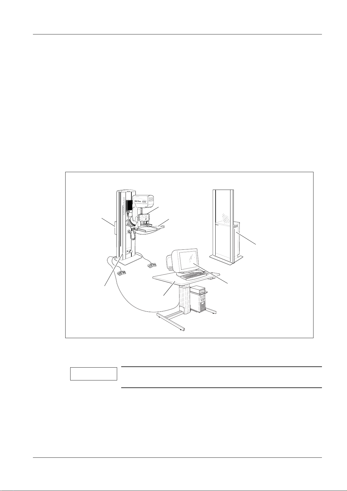
Sub-assemblies, overview 5
The components shall be placed according to the figure below .
Biopsy unit
Biopsy
controller
X
m
m
X
X
m
m
Y
m
m
Z
Y
Y
Z
Z
X
Z
Y
CCD camera
Generator
Stand with
X-ray unit
Workstation table
Workstation
Fig. 1 MAMMOMAT 3000 Nova with digital biopsy and spot imaging system Opdimar
NOTE
The workstation shall be placed at least 1.5 m from the object
table of the stand.
Siemens-Elema AB Register 3 SPB7-230.033.12 Page 1 of 26 Opdimar
Solna, Sweden Rev. 01 09.02 SPS-UD Installation
Page 16

5 - 2 Installation
Removal of MAMMOMAT stand covers 5
MAMMOMAT stand with separate rear side covers 5
WARNING
High voltage!
Life-threatening electric shock hazard exists.
Switch off the power to the system with the main circuit breaker.
Left rear side cover 5
1. Remove the scre w (5/Fig. 2) at the t op of the stand.
2. Pry loose the plastic strip (2/ Fig. 2) using a screwdriver or simil ar tool.
3. Remove the screws (3/Fig. 2) and remove the cov er (6/Fig. 2).
Right rear side cover 5
1. Remove the screw (1/Fig. 2), proceed as f or the left side cover and remove the
right side cover (4/Fig. 2).
Middle rear cover 5
1. Remove the two screws (7/Fig. 2) at the t op of the stand.
2. Remove the cover (8/Fig. 2) by lif ting it up.
1
7
9
4
Fig. 2 Removal of covers
8
5
6
3
2
OPD00150
Opdimar Register 3 SPB7-230.033.12 Page 2 of 26 Siemens-Elema AB
Installation Rev. 01 09.02 SPS-UD Solna, Sweden
Page 17

Installation 5 - 3
MAMMOMAT stand with single rear cover 5
WARNING
High voltage!
Life-threatening electric shock hazard ex ists.
Switch off the power to the system with the main circuit breaker.
Rear cover 5
1. Remove the screws (1/Fig. 3) at the top of the stand.
2. Pry loose the plastic strips (2/Fi g. 3) on both sides using a screwdriver or si milar
tool.
3. Remove the screws (3/Fig. 3) on both s ides and remove the cover (4/Fig. 3).
1
4
3
2
Fig. 3 Removal of covers
OPD00266
Siemens-Elema AB Register 3 SPB7-230.033.12 Page 3 of 26 Opdimar
Solna, Sweden Rev. 01 09.02 SPS-UD Installation
Page 18

5 - 4 Installation
Installation of biopsy controller holders 5
The biopsy controller is attached to the rear cover of the stand. To install the holders
proceed as follows:
1. Attach the two drilling template s (1/Fig. 4) included in this document on the inside
of the rear cover according to Fig. 4. The template marked B shall be placed
underneath the template marked A with no space between t hem. Make sure that
the templates are centered and that t he sides of the templates are parallel to t he
rear cover sides.
2. Drill five holes with a 5 mm drill in the rear cover according to the templates.
3. Install the three holders ( 2/Fig. 4) by using the nuts (3/Fi g. 4).
4. Install the two standoffs ( 4/Fig. 4) by using the screws (5/Fig. 4) and the washers
(6/Fig. 4).
UP
985 – 5 mm
A
2
3
B
1
6
4
Fig. 4 Rear cover, from the back side
Opdimar Register 3 SPB7-230.033.12 Page 4 of 26 Siemens-Elema AB
Installation Rev. 01 09.02 SPS-UD Solna, Sweden
5
OPD00267
Page 19

Installation 5 - 5
5. Install the rear cover (2/F ig. 5) on the stand and attach the biops y controller
(1/Fig. 5) to the holders. Switch on the power-on switch on the biopsy contr oller.
2
1
OPD00152
Fig. 5 Biopsy controller
Siemens-Elema AB Register 3 SPB7-230.033.12 Page 5 of 26 Opdimar
Solna, Sweden Rev. 01 09.02 SPS-UD Installation
Page 20

5 - 6 Installation
Modification of MAMMOMAT stand 5
MAMMOMAT with serial number lower than 5200 must be updated with new software.
1. Replace the existing software on board D801 wi th the V2.2 (or higher) software.
NOTE
If upgrading from a version lower than V1.5, the AEC have to be
upgraded, see Update Instruction, UI 001/96.
Modification of MAMMOMAT generator 5
Replacing board D702 5
MAMMOMAT with serial number lower than 3242 must be updated with a new board
D702.
1. Pry loose the plastic strips (1/ Fig. 6), using a screwdriver or similar tool.
2. Remove the sixteen screws (2/Fig. 6) and remove the front cover (3/Fig. 6).
2
3
Fig. 6 Removal of generator front cover
3. Remove the board D702 in Fig. 7 from the generator.
4. Install software V2.2 (or higher ) on the new board D702.
5. Install the new board D702 Fig. 7 in the generator .
NOTE
If upgrading from a version lower than V1.5, the AEC have to be
upgraded, see Update Instruction, UI 001/96.
1
OPD00153
Opdimar Register 3 SPB7-230.033.12 Page 6 of 26 Siemens-Elema AB
Installation Rev. 01 09.02 SPS-UD Solna, Sweden
Page 21

Installation 5 - 7
D702
OPD00154
Fig. 7 Board D702
Replacing software 5
MAMMOMAT with serial number lower than 5200 must be updated with new softw are.
1. Replace the existing software on boar ds D740, D701 and D702 (if not already
done in previous steps) with the V2. 2 (or higher) software.
NOTE
If upgrading from a version lower than V1.5, the AEC have to be
upgraded, see Update Instruction, UI 001/96.
Installing isolation board D707 5
If not already done in conjunction with instal lation of printer (option), an isolation board
D707 (see Fig. 10) shall be installed. Install the board according to Installati on Instructions
for Isolation P.c. Board D707, RX B7-120.031.03. ...
Siemens-Elema AB Register 3 SPB7-230.033.12 Page 7 of 26 Opdimar
Solna, Sweden Rev. 01 09.02 SPS-UD Installation
Page 22

5 - 8 Installation
Restoring installation parameters 5
If the software has been changed, the installation parameters ha ve to be restored.
Proceed as follows:
1. Switch on the MAMMOMAT. Install the service PC, (see Working with the Service
PC in MAMMOMAT 1000/3000/3000 Nova Installation and Start-Up Ins truction).
2. Start the service program with the new servi ce diskette.
3. Select
copy the previously stored data from th e hard disk to the installation ar ea of the
MAMMOMAT.
4. Select
focus.
5. Select
(tungsten) anode depending on the system conf iguration.
NOTE
NOTE
6. Select
identical to the values noted in st ep 3. above, if not correct them.
Main menu => Backup => Copy disk to instal lation area => All
Main menu => Configuration => Power
Main menu => Configuration => Anode
For serial numbers lower than 5000 the W anode should always
be enabled.
For serial numbers higher than 5000 it depends on what the customer ordered, if the W anode should be enabled or disabled. Thi s
can be checked by looking at the filter disk in the collimator. If the
filter disk has only two filters and a lead strip mounted instead of
a third filter, the W anode should be disabled.
Main menu => Configuration => Power
and note the values for all four
and enable/disable the W
. Make sure that the values are
. This will
7. Select
and set the switch to ON.
8. Switch off the MAMMOMAT with the main circuit breaker.
Main menu
=>
Configuration => Mischelaneous=> Casset te loaded switch
Opdimar Register 3 SPB7-230.033.12 Page 8 of 26 Siemens-Elema AB
Installation Rev. 01 09.02 SPS-UD Solna, Sweden
Page 23

Installation 5 - 9
Connection of cables 5
The biopsy controller is the central unit for the cable connections. The cables are
connected to the biopsy controller according to the figure below:
CCD camera
Workstation
Printer
(option)
Fig. 8 Connection of cables
D110
X112
X110
X111
D101/X101
A
B
M3000 printer/
Service PC
X201
X202
X203
X204
X205
M3000 generator
Biopsy controller
Mains cable
X207
X206
Z801
X2 X885
Biopsy unit
(M3000 stand)
Protective
earth cable
X880
M3000 stand
Siemens-Elema AB Register 3 SPB7-230.033.12 Page 9 of 26 Opdimar
Solna, Sweden Rev. 01 09.02 SPS-UD Installation
Page 24

5 - 10 Installation
Cables to MAMMOMA T generator (and printer if present) 5
To lay the cables, proceed as follows:
1. Disconnect the printer cable ( if connected) from the MAMMOMAT generator.
2. Open the cable duct between the generator and the st and and lift up the cable (if
present).
The cable will be reused to connect the pri nter to X205 on the biopsy controll er.
3. Place the new cable with connectors marked X20 6 and X2 in the cable duct
between the generator and the biopsy control ler. Use compartment according to
the figure below.
Serial number higher than 3000
Cable X206-X2
Fig. 9 Cable-duct compartments
Serial number lower than 3000
OPD00156
Opdimar Register 3 SPB7-230.033.12 Page 10 of 26 Siemens-Elema AB
Installation Rev. 01 09.02 SPS-UD Solna, Sweden
Page 25

Installation 5 - 11
4. Connect the cable to the MAMMOMAT generator connector X2 on D707,
see Fig. 10.
NOTICE
For MAMMOMAT with a serial number >3000, the shielding of the
cable shall be connected to the generator by means of the chassie ground clamp on the rear wall of the generator, below the
D700 board. The shielding of the cable is accessible by cutting
the two cable ties and removing the protective plastic sleeve.
This is to ensure electromagnetic compatibility of the equi pment .
Chassie ground clamp
Fig. 10 Connection of cable to the generator
X2
OPD00157
Siemens-Elema AB Register 3 SPB7-230.033.12 Page 11 of 26 Opdimar
Solna, Sweden Rev. 01 09.02 SPS-UD Installation
Page 26

5 - 12 Installation
5. Connect the other end of the cable to the biops y controller connector X206 in
Fig. 11.
X201
X202
X203
Ferrite
X204
OPD00453
X205 X206 X207 Mains cable
Fig. 11 Connection of cables to the biopsy controller
Protective earth cable
6. Connect the MAMMOMAT printer (if applicable) to X205 on t he biopsy controller
using the previously removed prin ter cable modified in the foll owing way:
If the shield braid of the pri nter cable is bare where it was connec ted to the
generator bottom plate, the cable shal l be insulated.
If connected, eject pin 1 on the print er connector side and insulate.
7. Strain relieve the cable at the bot tom of the stand.
NOTE
NOTE
The X205 connector is also used for connection of the service PC.
The switch S3 (TEST) on PC Board D702 is not used with Opdima.
The software will sense if a printer or a service PC is connected.
8. Connect the printer to the same wall socket (branch circuit) as the workstat ion.
The wall socket must be marked according to Fig. 24.
9. Close the cable duct cover and ins tall the front cover of the generator.
Opdimar Register 3 SPB7-230.033.12 Page 12 of 26 Siemens-Elema AB
Installation Rev. 01 09.02 SPS-UD Solna, Sweden
Page 27

Installation 5 - 13
Cables to biopsy unit 5
The cable with connectors marked X207 and X885 is laid between the biopsy controller
and the biopsy unit connector of the MAMMOMAT stand.
1. Connect the cable to X207 on the biopsy controll er and X885 on the stand, see
Fig. 12 (serial number higher than 3000) or Fig. 13 (serial number lower than
3000).
NOTICE
The evaluation unit can not be used with Opdima.
If an evaluation unit i s connected to the MAMMOMAT this must be
disconnected at X885.
Power connection 5
NOTICE
The mains cable supplies the biopsy controller with 230 V AC from the stand. Together
with the mains cable a protective earth cable shall be installed.
The connection between the biopsy controller and the stand can be made in two ways
depending on MAMMOMAT serial number:
The evaluation unit can not be used with Opdima.
If an evaluation unit is connected to the MAMMOMAT, the power
connection of the evaluation unit must be disconnected at the
stand.
• Serial number higher than 3000: biopsy controller mains connector to MAMMOMAT
3000 connector Z801, see Fig. 12
• Serial number lower than 3000: biopsy controller mains connector to MAMMOMAT
connector X881, see Fig. 13
1. Connect the cables, mains cable and prote ctive earth cable, to Z801 or X881 on
the stand.
The brown cord (1/Fig. 12) to Z801-1, t he blue cord (2/Fig. 12) to Z801-2 and the
green-yellow cord (3/Fig. 12)to X880- 4 for MAMMOMAT serial number higher
than 3000. For MAMMOMAT serial number lo wer than 3000, connect accordin g to
Fig. 13. Strain relieve the c able with the supplied strain r elief clamp.
2. Connect the three-pole connector of the mains cable to the biopsy controller, see
Fig. 11.
Z801
1 (BN)
2 (BU)
Protective earth cable
Fig. 12 Connec tion of mains cable, protective earth cable and X885, serial number higher than 3000
Siemens-Elema AB Register 3 SPB7-230.033.12 Page 13 of 26 Opdimar
Solna, Sweden Rev. 01 09.02 SPS-UD Installation
3 (GNYE)
OPD00474
X885
Page 28

5 - 14 Installation
X881
3 (GNYE)
Protective earth cable
1 (BN)
2 (BU)
X885
Fig. 13 Connection of mains cable, protective earth cable and X885, serial number lower than 3000
OPD00475
Cables to CCD camera 5
The CCD camera including cab le with connec tors marke d X201 and X202 is connec ted to
the biopsy controller.
1. Connect the cable to X201 and X202 on the biopsy cont roller, see Fig. 11.
CAUTION
2. Remove the screws (1/Fig. 14) and r emove the cover (2/Fig. 14) of the objec t table
arm.
Sensitive electronic equipment!
Risk of damaging the camera.
Do not touch the pins in the contacts of the CCD camera.
1 2
Fig. 14 Object table arm before installation
Opdimar Register 3 SPB7-230.033.12 Page 14 of 26 Siemens-Elema AB
Installation Rev. 01 09.02 SPS-UD Solna, Sweden
OPD00161
Page 29

Installation 5 - 15
1. Install a new thread (1/Fig. 15).
1
Fig. 15 Installation of thread
OPD00162
2. Install the holder (1/Fig. 16) with the pull relief de vice, using included Allen screws
(2/Fig. 16).
21
OPD00163
Fig. 16 Object table arm after installation
Siemens-Elema AB Register 3 SPB7-230.033.12 Page 15 of 26 Opdimar
Solna, Sweden Rev. 01 09.02 SPS-UD Installation
Page 30

5 - 16 Installation
Installation of cable duct 5
Four cables are laid from the bottom of the biopsy controller in a cable duct to the cable
outlet cover (3/Fig. 17). To install the cable duct on the rear side of the stand proceed as
follows:
1. Attach the cable duct (2/Fi g. 17) to the rear cover by removi ng the protective strips
from the attached Velcro strips and pl ace the duct flush with the biopsy contr oller
(1/Fig. 17). Secure the cable duct to the two standoffs (5/Fig. 17 ) with the
delivered screws and washers.
UP
1
4
5
2
3
OPD00164
Fig. 17 Cable duct
50m
m
25mm
Modification of cable outlet cover 5
To allow the cables to pass through the cable outlet cov er, the cover has to be modified
according to the following:
1. Cut an opening centrally on the cable outlet cover (4/Fig. 17). The open ing should
be approximately 50 x 25 mm.
2. Attach the supplied plastic str ip around the opening of the cable outlet cover
(4/Fig. 17).
3. Install the cable outlet c over (4/Fig. 17).
4. Mount the previously removed stand covers.
Opdimar Register 3 SPB7-230.033.12 Page 16 of 26 Siemens-Elema AB
Installation Rev. 01 09.02 SPS-UD Solna, Sweden
Page 31

Installation 5 - 17
Installation of workstation 5
Preparing the workstation table (option) 5
The workstation table ( option), a mot orized v ertically adjustab le tab le , shal l be used to put
the workstation components to the Opdimar system on. The vertical adjustment device
includes a transformer, which is not mounted on delivery.
CAUTION
Handschalter
5
Fig. 18 Transfor m e r
The workstation table must not be overloaded.
Any additional equipment is added at your own risk and the maxi-
mum load of 80 kg must not be exceeded.
2
3
1
4
Opd00494
1. Remove the screws on the underside of the tabl etop and use them when
mounting the transformer (1/Fig . 18).
Place the transformer so that the co nnectors are turned to the column.
2. Connect the cable from the control uni t (2/Fig. 18) for the verticall y adjustment to
the connector marked “Handschalter” (3/Fig. 18).
3. Connect the cable from the motor (4/Fi g. 18) for the vertically adjus tment to the
other connector (5/Fig. 18 ).
Siemens-Elema AB Register 3 SPB7-230.033.12 Page 17 of 26 Opdimar
Solna, Sweden Rev. 01 09.02 SPS-UD Installation
Page 32

5 - 18 Installation
4. Place the workstation table outs ide the patient environment of safety reasons.
Patient environment is determined by IEC 6060 1-1-1 as 1.5 m away from the
patient.
Cables 8 m
Cable 1,5 m
Biopsy
controller
Stand
Biopsy unit
Min.1,5 m
Cable (workstation table) 2 m
Workstation
CCD camera holder
150
Cable duct
CCD camera
Generator
Fig. 19 System site overview
NOTE
OPD00489
There must be enough space around the workstation table so t hat
it safely can be vertically adjusted.
Opdimar Register 3 SPB7-230.033.12 Page 18 of 26 Siemens-Elema AB
Installation Rev. 01 09.02 SPS-UD Solna, Sweden
Page 33

Installation 5 - 19
5. If the workstation table stands on an unev en floor, it can be adjusted with the
adjustable screws on the framework.
HEWLETT!
PACKARD!
Fig. 20 Shelves
6. Place the monitor, the keyboard and the mouse on the tabletop. Make sure that all
the equipment is within the edges of t he tabletop.
2
1
OPD00502
7. Let the cables from the monitor, the keyboard and t he mouse pass through the
hole at the back of the tabletop.
8. Place the main unit to the right on its shelf (1/Fig. 20).
9. Mount the MO unit shelf close to the main uni t (2/Fig. 20).
10. Place the MO unit to the right on t he shelf (2/Fig. 20).
Siemens-Elema AB Register 3 SPB7-230.033.12 Page 19 of 26 Opdimar
Solna, Sweden Rev. 01 09.02 SPS-UD Installation
Page 34

5 - 20 Installation
Connecting the workstation 5
1. Connect workstation cable marked X203 to t he biopsy controller connector X203,
see Fig. 21, and the other end (X101) of the cabl e to the workstation connector
(10/Fig. 25).
CAUTION
Connecting the cable to the wrong connector may cause severe
damage to the equipment.
2. Attach ferrite on the cable on the bio psy controller side, see Fig. 21.
X201
X202
X203
Ferrite
X204
OPD00453
X205 X206 X207 Mains cable
Fig. 21 Biopsy controller
Protective earth cable
3. Connect the workstation cable marked X204 t o the biopsy controller connector
X204 in Fig. 21 and the other end of the cable to t he workstation connector
A (6A/Fig. 25) and B (6B/Fig. 25).
4. Attach ferrite on the cable on the bio psy controller side, see Fig. 21.
5. Mount the touch protection over the connect ors X203 and X204.
-Place the plastic plate (1/Fig. 22) behind the connectors X203 and X204.
-Place the plastic cover (2/Fig. 22) on the other side of the connectors.
-Fasten the plastic screws (3/Fig. 22).
3
1
2
Biopsy controller
Fig. 22 Mounting the touch protection
OPD0
Opdimar Register 3 SPB7-230.033.12 Page 20 of 26 Siemens-Elema AB
Installation Rev. 01 09.02 SPS-UD Solna, Sweden
Page 35

Installation 5 - 21
6. Connect the MO unit SCSI cable to the wo rkstation SCSI connector (9/Fig. 25).
7. Connect the MO unit cable to one of the two connectors of t he MO unit. Fit the
terminator to the other connector of the MO unit.
For switch settings, SCSI ID and terminati on see Ultra 10 MO unit in Mammomat
1000/3000/3000 Nova - Opdimar Service Instructions.
CAUTION
Make sure that the SCSI cables are properl y connected and fixed
to the units and that the cable is not bent too much just behind
the MO unit. Also, check that the MO unit is terminat ed correctly.
If disregarded, thi s might generate a lot of prob lems e.g. fail ure to
write images to MO disk, corrupted MO disk or corrupted hard
disk.
8. Connect the mouse to the keyboard.
9. Connect keyboard and mouse (5/Fig. 25).
10. Connect monitor cable to t he workstation connector (11/Fig. 25) .
11. Connect Ethernet cable (7/Fig . 25).
12. Mark the wall socket connected to the same br anch circuit as the MAMMOMAT
(Fig. 23) with label according to Fig. 24.
The power distribution to the system is shown i n Fig. 23.
1-phase
L1 N
PE
10A
2-phase
L1L2
10A
N
PE
Off
On
Power On-Off breaker
Fig. 23 Power distribution
Workstation
Power connection
in MAMMOMAT 3000-stand
Off
On
Power On-Off breaker
Power connection
in MAMMOMAT 3000-stand
Workstation
OPD00166
Siemens-Elema AB Register 3 SPB7-230.033.12 Page 21 of 26 Opdimar
Solna, Sweden Rev. 01 09.02 SPS-UD Installation
Page 36

5 - 22 Installation
13. If a voltage selector switch exi sts, ensure the line voltage select or switch (2/ Fig.
25) is set to the appropriate set ting: 115V or 230V.
CAUTION
14. Connect the AC power cords of the main unit, the moni tor, the MO unit, the local
Opdimar printer (if present) and the MAMMOMAT printer (if present) to the wall
socket marked with label.
It is advisable to use an extension cord with at least three outlets.
CAUTION
Plugging a 115V power cord into a 230V connector will severely
damage the system.
The workstation and the printer must be grounded to the same
potential as the MAMMOMAT.
Connect the wall socket for the workstation and printer power
supply to the same branch circuit as the MAMMOMAT power supply.
(The workstation table can be connected to any branch circuit.)
Opdimar Register 3 SPB7-230.033.12 Page 22 of 26 Siemens-Elema AB
Installation Rev. 01 09.02 SPS-UD Solna, Sweden
Page 37

Installation 5 - 23
H
E
W
LETT
P
A
C
KARD
Opdima mains power
supply outlet!
OPD00511
Fig. 24 Mains marking label
1
6A
6B
2
3
4
11
5
10
A
B
7
9
8
OPD00589
1 Mains power supply
2 Line voltage selector (if applicable)
3 Power on / off
4 MIC
5 Keyboard interface
6A Mammomat interface via biopsy controller (X204)
6B Biopsy controller interface (X204)
7 Network connector
8 Parallell port to local printer
9 SCSI interface
10 Camera interface via biopsy controller (X203)
11 Monitor interface
Fig. 25 Workstation main unit connectors
Siemens-Elema AB Register 3 SPB7-230.033.12 Page 23 of 26 Opdimar
Solna, Sweden Rev. 01 09.02 SPS-UD Installation
Page 38

5 - 24 Installation
Connecting the workstation to the network 5
The Opdima workstation can be connected to a netw ork, partly for the use of DICOM and
also for networked printers.
1. Connect one end of the network cable (included i n the delivery) to the workstati on.
2. Connect the other end of the network cable to a net work socket.
3. Log in with the user name “service”. The password is obtained from Siemens
Service Centre.
4. Press the Service button in the mode select ion dialog, see Selection of mode in
MAMMOMAT 1000/3000/3000 Nova - Opdimar Service Instructions.
5. Press the Advanced service button in the ser vice dialog, see Use of Advanced
service functions in MAMMOMAT 1000/3000/3000 Nova - Opdima r Service
Instructions.
6. In Advanced service configure the network parameters, see Network setti ngs in
MAMMOMAT 1000/3000/3000 Nova - Opdimar Service Instructions.
For physical limitations of t he network see Mammomat 1000/3000/3000 Nova Opdimar Planning Guide.
Installation of Opdima printer (option) 5
Stand alone Opdima system:
When the Opdima system is stand alone (not connected to a network) it is possible to
install a Codonics NP-1660 or NP-1600 printer to Opdimar as a stand alone printer
connected to the network connector.
NOTE
The following equipment is needed:
It is also possible to connect a stand alone postscript printer to
the parallel or network connector of the workstation, see Use of
printer setup in MAMMOMAT 1000/3000/3000 Nova - Opdimar
Service Instructions.
• Codonics printer NP-1660 or NP-1600
• Crossover network cable
Proceed as follows to install the printer:
1. Connect one end of the network cable to the workst ation (9/Fig. 25).
2. Connect the other end of the network cable to t he printer.
3. Connect the mains cable of the printer to the wall socket marked with label,
see Fig. 24.
CAUTION
4. Set the printer IP address to 10.10 .10.2 see the User’s Manual for the Codonics
NP-1660 or NP-1600.
Opdimar Register 3 SPB7-230.033.12 Page 24 of 26 Siemens-Elema AB
Installation Rev. 01 09.02 SPS-UD Solna, Sweden
The printer must be grounded to the same potential as the
MAMMOMAT.
Connect the printer power supply to the same branch circuit as
the MAMMOMAT power supply.
Page 39

Installation 5 - 25
5. Select Scaled in printer setup i n the advanced service dialog, see St and alone
Opdima system in MAMMOMAT 1000/3000/3000 Nova - Opdimar Serv ice
Instructions.
Networked Opdima system:
When the Opdimar system is network ed it is poss ib l e to c onfi gure t he system t o print t o a
printer connected to the network or a local postscript printer connected to the parallel
interface of the workstation.
NOTE
Proceed as follows to install the network printer:
1. Add access to the network printer in the advanced service dialog, see Networked
Opdima system in MAMMOMAT 1000/3000/3000 Nova - Opdimar Serv ice
Instructions.
2. Select printer in the advan ced service dialog, see Networked Opdima sy stem in
MAMMOMAT 1000/3000/3000 Nova - Opdimar Service Instructi ons.
It is also possible to connect a stand alone postscript printer to
the parallel connector of the workstation, see Select printer in
MAMMOMAT 1000/3000/3000 Nova - Opdimar Service
Instructions.
Siemens-Elema AB Register 3 SPB7-230.033.12 Page 25 of 26 Opdimar
Solna, Sweden Rev. 01 09.02 SPS-UD Installation
Page 40

5 - 26 Installation
Strain relieving the cables 5
If the workstation table (option) is used with the Opdima system, the cables from the
workstation components and from the MAMMOMAT must be strain relieved by cabl e
clamps at the back of the MO unit shelf accordi ng to the figure below.
• To ensure that the cables have enough length for the verti cal adjustment, let the
workstation table be in its highest possible position when strain relie ving the cables.
• Use cable ties to arrange the cables in an organized way and make s ure that the cables
can run without a risk of getting caught .
A0BCDEFGH
1
SCSI CONNECTOR
AC IN
1
SCSI ID
F GND
Fig. 26
Opd00499
Keyboard
Printer
(option)
Biopsy
controller
Monitor
Camera
controller
Functional test (workstation table) 5
Before the installed workstation table (option) is handed over to the customer, check that
the workstation table can be vertically adjusted between the highest and lowest possible
positions properly and safety.
Opdimar Register 3 SPB7-230.033.12 Page 26 of 26 Siemens-Elema AB
Installation Rev. 01 09.02 SPS-UD Solna, Sweden
Page 41

Final procedures 6
General 6
The following procedures shall be performed:
• Starting up the workstation, see Page 6 - 2
• Country settings,
see chapter Service mode in MAMMOMAT 1000/3000/3000 Nova - Opdimar Se rvice
Instructions
• Test of units,
see chapter Service mode in MAMMOMAT 1000/3000/3000 Nova - Opdimar Se rvice
Instructions
• CCD camera calibration,
see chapter Service mode in MAMMOMAT 1000/3000/3000 Nova - Opdimar Se rvice
Instructions
• Calibration of the biopsy unit,
see chapter Service mode in MAMMOMAT 1000/3000/3000 Nova - Opdimar Se rvice
Instructions
• Verifying the calibration of the biopsy uni t,
see chapter Measures after service in MAMMOMAT 1000/3000/3000 Nova - Opdimar
Service Instructions
6 - 1
• Check of Opdimar AEC,
see chapter Measures after service in MAMMOMAT 1000/3000/3000 Nova - Opdimar
Service Instructions
• Check of resolution,
see chapter Measures after service in MAMMOMAT 1000/3000/3000 Nova - Opdimar
Service Instructions
• Activate DICOM (optional),
see DICOM option in chapter Service mode in MAMMOMAT 1000/3000/3000 Nova Opdimar Servic e Instructions
• Network settings,
see chapter Service mode in MAMMOMAT 1000/3000/3000 Nova - Opdimar Se rvice
Instructions
• Printer setup (optional),
see Use of printer setup in chapter Service mode in MAMMOMAT 1000/3000/3000 Nova
- Opdimar Service Instruct ions
• Mounting of covers, see Page 6 - 2
• Protective earth measurement,
see chapter Measures after service in MAMMOMAT 1000/3000/3000 Nova - Opdimar
Service Instructions
• Fill in the IVK list or report the IVK component s to your responsible uptime service cent er
(USC).
• Performing of DHHS maintenance, see Page 6 - 3
NOTICE
Siemens-Elema AB Register 3 SPB7-230.033.12 Page 1 of 4 Opdimar
Solna, Sweden Rev. 01 09.02 SPS-UD Installation
The Opdimar external diaphragm must be used for tests and calibrations involving radiation.
Page 42

6 - 2 Final procedures
Starting up the MAMMOMAT 6
Switch on the MAMMOMAT.
Starting up the workstation and login 6
The workstation is started according to instructions in Starting up the workstation and
login in Supplement to the Instructions for Use MAMMOMAT 3000 - Opdimar.
Use the user name “service” and the password obtained from Siemens service center
when entering the system.
To obtain optimal picture, adjust the monitor settings as follow:
Brightness: 50260
Contrast: 100
Starting up the MO unit 6
HEWLETT
PACKARD
Fig. 1 Magneto-optical drive (HP)
1. Insert the MO disk, type 2.3 GB MO disk
2. For switch settings, SCSI ID and terminat ion see Ultra 10/Ultra 1 MO unit in
MAMMOMAT 1000/3000/3000 Nova - Opdimar Service Instruct ions.
Installation of software 6
The software is installed in the factory before delivery. If the software for any reason
needs to be reinstalled, refer to Reinstallation of software in MAMMOMAT 1000/3000/
3000 Nova - Opdimar Service Instructions .
Mounting of covers 6
Mount the covers previously removed.
Filling in of IVK list 6
Fill in the IVK list or report the IVK component s to your responsible uptime service center
(USC).
Opdimar Register 3 SPB7-230.033.12 Page 2 of 4 Siemens-Elema AB
Installation Rev. 01 09.02 SPS-UD Solna, Sweden
Page 43

Final procedures 6 - 3
Performing of DHHS maintenance 6
In the USA, perform maintenance according to MAMMOMAT 300/3000, MAMMOMAT
3000 Modular incl. Stereotactic Biopsy Attachment and Opdimar DHHS Maintenance
Instructions and fill in MAMMOMAT 300/3000, MAMMOMAT 3000 Modular incl.
Stereotactic Biopsy Attachment and Opdimar Measurement Certificates.
NOTE
The DHHS Maintenance Instructions and Measurement Certificates delivered with the Opdimar also includes the measurements to be performed on the MAMMOMAT. Therefore the DHHS
Maintenance Instructions supplied with the MAMMOMAT can be
removed. However, the Measurement Certificates supplied with
the MAMMOMAT should be kept for future r eference, if i t contains
previous measurement results.
Siemens-Elema AB Register 3 SPB7-230.033.12 Page 3 of 4 Opdimar
Solna, Sweden Rev. 01 09.02 SPS-UD Installation
Page 44

6 - 4 Final procedures
This page intentionally left blank.
Opdimar Register 3 SPB7-230.033.12 Page 4 of 4 Siemens-Elema AB
Installation Rev. 01 09.02 SPS-UD Solna, Sweden
Page 45

Changes to previous version 7
Chapter Title Changes to previous version
0 Chapter completely revi sed.
1 Documents required Technical information TI219 removed.
7 - 1
Meters and appliances
required
5 Connecting the worksta-
tion
6 General New information regarding the former LINA CARDS. Today
Filling in of IVK list New chapter.
New AEC calibration plexiglass.
- New information in step 12.
- New Fig 23.
Siemens use an IVK list instead.
Siemens-Elema AB Register 3 SPB7-230.033.12 Page 1 of 2 Opdimar
Solna, Sweden Rev. 01 09.02 SPS-UD Installation
Page 46

7 - 2 Changes to previous version
This page intentionally left blank.
Opdimar Register 3 SPB7-230.033.12 Page 2 of 2 Siemens-Elema AB
Installation Rev. 01 09.02 SPS-UD Solna, Sweden
Page 47

150 mm
Drilling template A
Drill five holes with a 5 mm drill
according to template A and B.
Place template B underneath
template A with no space
between them.
Check distances before drilling!
230 mm
OPD00268
Page 48

This page intentionally left blank
Page 49

195 mm
(to next hole)
Drilling template B
140 mm
OPD00269
Page 50

This page intentionally left blank
 Loading...