

Page 1

MAMMOMAT 1000/3000 Nova
SP
Installation
Installation and Start-Up Instructions
from Serial No. 9000
© Siemens AG 2003
The reproduction, transmission or
use of this document or its contents
is not permitted without express
written authority. Offenders will be
liable for damages. All rights,
including rights created by patent
grant or registration of a utility
model _or_ design,_are_ reserved.
Register 3 English
Print No.: SPB7-230.033.11.05.02 Doc. Gen. Date: 05.05
Replaces: SPB7-230.033.11.04.02
Page 2

0 - 2 Revision
Chapter Page Revision
All All 05
Document revision level
The document corresponds to the version/revision level effective at the time of system delivery. Revisions to hardcopy documentation are not automatically distributed.
Please contact your local Siemens office to order current revision levels.
Disclaimer
The installation and service of equipment described herein is to be performed by qualified personnel
who are employed by Siemens or one of its affiliates or who are otherwise authorized by Siemens or
one of its affiliates to provide such services.
Assemblers and other persons who are not employed by or otherwise directly affiliated with or authorized by Siemens or one of its affiliates are directed to contact one of the local offices of Siemens or
one of its affiliates before attempting installation or service procedures.
M1000/3000 Nova Register 3 SPB7-230.033.11 Page 2 of 8 Siemens AG
Installation and Start-Up Rev. 05 05.05 CS PS 24 Medical Solutions
Page 3

Contents 0 - 3
Page
1 _______Prerequisites __________________________________________________ 1 - 1
General . . . . . . . . . . . . . . . . . . . . . . . . . . . . . . . . . . . . . . . . .1 - 1
MAMMOMAT 1000 . . . . . . . . . . . . . . . . . . . . . . . . . . . . . . . . . 1 - 1
MAMMOMAT 3000 Nova . . . . . . . . . . . . . . . . . . . . . . . . . . . . . . 1 - 2
Meters and appliances, tools . . . . . . . . . . . . . . . . . . . . . . . . . . . . . . 1 - 3
Meters and appliances required . . . . . . . . . . . . . . . . . . . . . . . . . . . 1 - 3
Tools required . . . . . . . . . . . . . . . . . . . . . . . . . . . . . . . . . . . . 1 - 3
Important notes on start-up . . . . . . . . . . . . . . . . . . . . . . . . . . . . . . . 1 - 4
Checking and recording for the area of application of the X-ray decree (§16 Germany)1 - 4
Checking and recording for the DHHS area of application . . . . . . . . . . . . . . . 1 - 5
Sections . . . . . . . . . . . . . . . . . . . . . . . . . . . . . . . . . . . . . . . 1 - 5
Note on delivery state . . . . . . . . . . . . . . . . . . . . . . . . . . . . . . . . . . 1 - 5
2 _______Protective measures ____________________________________________ 2 - 1
Protective measures. . . . . . . . . . . . . . . . . . . . . . . . . . . . . . . . . . . 2 - 1
Delay times between two exposures . . . . . . . . . . . . . . . . . . . . . . . . . . 2 - 2
3 _______Preparatory work_______________________________________________ 3 - 1
General . . . . . . . . . . . . . . . . . . . . . . . . . . . . . . . . . . . . . . . . .3 - 1
Scope of delivery . . . . . . . . . . . . . . . . . . . . . . . . . . . . . . . . . . 3 - 1
Unpacking . . . . . . . . . . . . . . . . . . . . . . . . . . . . . . . . . . . . . . 3 - 1
Unpacking the stand. . . . . . . . . . . . . . . . . . . . . . . . . . . . . . . . . . . 3 - 2
Removing the transport safeguards . . . . . . . . . . . . . . . . . . . . . . . . . . . 3 - 3
Removing the swivel-arm system transport safeguard . . . . . . . . . . . . . . . 3 - 3
Transport safeguard for the lifting carriage . . . . . . . . . . . . . . . . . . . . . 3 - 3
Transport safeguard for the rotary motion . . . . . . . . . . . . . . . . . . . . . . . . 3 - 4
Ball bearings. . . . . . . . . . . . . . . . . . . . . . . . . . . . . . . . . . . . . . .3 - 5
Protective strips for the metal curtain . . . . . . . . . . . . . . . . . . . . . . . . . . 3 - 5
Unpacking the generator and mounting the radiation shield (optional) . . . . . . . . . 3 - 6
4 _______Installing the generator and the stand _____________________________ 4 - 1
Arranging the components . . . . . . . . . . . . . . . . . . . . . . . . . . . . . . . 4 - 1
Notes on installations with separate generator and separate control console. . . . 4 - 1
Free-standing radiation shield (option) . . . . . . . . . . . . . . . . . . . . . . . . . 4 - 2
Removing the generator cover . . . . . . . . . . . . . . . . . . . . . . . . . . . . . 4 - 2
Installing the cable ducts . . . . . . . . . . . . . . . . . . . . . . . . . . . . . . . . 4 - 3
Installations with separate control console . . . . . . . . . . . . . . . . . . . . . 4 - 3
Laying the cable harness . . . . . . . . . . . . . . . . . . . . . . . . . . . . . . . . 4 - 4
Installations with separate control console . . . . . . . . . . . . . . . . . . . . . 4 - 5
Aligning the stand . . . . . . . . . . . . . . . . . . . . . . . . . . . . . . . . . . . . 4 - 6
5 _______Cable connections______________________________________________ 5 - 1
EMC measures . . . . . . . . . . . . . . . . . . . . . . . . . . . . . . . . . . . . . 5 - 1
Siemens AG Register 3 SPB7-230.033.11 Page 3 of 8 M1000/3000 Nova
Medical Solutions Rev. 05 05.05 CS PS 24 Installation and Start-Up
Page 4

0 - 4 Contents
Page
EMC measures at the cable entry . . . . . . . . . . . . . . . . . . . . . . . . . . . 5 - 1
Fitting the hose clamps and ferrite sleeves . . . . . . . . . . . . . . . . . . . . . 5 - 1
Note on separate control console and separate generator . . . . . . . . . . . . . 5 - 2
EMC measures on the bottom plate . . . . . . . . . . . . . . . . . . . . . . . . . . 5 - 3
Fitting the cables X1, X8 and X9 onto the bottom plate . . . . . . . . . . . . . . 5 - 3
Connecting the stand cable-harness . . . . . . . . . . . . . . . . . . . . . . . . . . 5 - 4
High-voltage connector . . . . . . . . . . . . . . . . . . . . . . . . . . . . . . . 5 - 4
Connecting the high-voltage connector. . . . . . . . . . . . . . . . . . . . . . . . . 5 - 5
Connecting the cable harness to the generator . . . . . . . . . . . . . . . . . . . . 5 - 6
Unit control cable X1 . . . . . . . . . . . . . . . . . . . . . . . . . . . . . . . . 5 - 6
Filament cable X8. . . . . . . . . . . . . . . . . . . . . . . . . . . . . . . . . . 5 - 6
Power supply cable X14 . . . . . . . . . . . . . . . . . . . . . . . . . . . . . . 5 - 6
AEC signal cable X10 and X11 . . . . . . . . . . . . . . . . . . . . . . . . . . . 5 - 6
Rotating anode cable X9 . . . . . . . . . . . . . . . . . . . . . . . . . . . . . . 5 - 7
Installations with separate control console and separate generator . . . . . . . . 5 - 8
Main voltage connection . . . . . . . . . . . . . . . . . . . . . . . . . . . . . . . .5 - 10
Connecting the incoming mains to the stand (400 V, 2-phase). . . . . . . . . . . . .5 - 11
400 V 2-phase connection . . . . . . . . . . . . . . . . . . . . . . . . . . . . .5 - 11
Connecting the mains supply to the generator (400 V, 2-phase) . . . . . . . . . . . .5 - 12
Measures for changing from 2-phase to 1-phase connection . . . . . . . . . . .5 - 13
6 ______ Mains connection and power supply_______________________________6 - 1
Checks before powering up the generator . . . . . . . . . . . . . . . . . . . . . . . 6 - 1
Measuring the line resistance . . . . . . . . . . . . . . . . . . . . . . . . . . . . . 6 - 1
Checking the line voltage in the generator . . . . . . . . . . . . . . . . . . . . . . . 6 - 2
Checking the supply voltages . . . . . . . . . . . . . . . . . . . . . . . . . . . . . 6 - 3
7 ______ Attaching the swivel-arm covers __________________________________7 - 1
Attaching the swivel-arm covers . . . . . . . . . . . . . . . . . . . . . . . . . . . . 7 - 1
Arranging the swivel-arm system . . . . . . . . . . . . . . . . . . . . . . . . . . 7 - 1
Connecting the cables to control-button boards and patient handles . . . . . . . 7 - 1
Attaching the side covers . . . . . . . . . . . . . . . . . . . . . . . . . . . . . . 7 - 2
Attaching the front cover . . . . . . . . . . . . . . . . . . . . . . . . . . . . . . 7 - 2
8 ______ Checking the microprocessors ___________________________________8 - 1
Microprocessors . . . . . . . . . . . . . . . . . . . . . . . . . . . . . . . . . . . . 8 - 1
9 ______ Checks without high voltage _____________________________________9 - 1
Checks without high voltage . . . . . . . . . . . . . . . . . . . . . . . . . . . . . . 9 - 1
10 _____ Checks with high voltage _______________________________________10 - 1
Preparation . . . . . . . . . . . . . . . . . . . . . . . . . . . . . . . . . . . . . . .10 - 1
kV-adjustment . . . . . . . . . . . . . . . . . . . . . . . . . . . . . . . . . . . . .10 - 2
Filament . . . . . . . . . . . . . . . . . . . . . . . . . . . . . . . . . . . . . . . .10 - 4
M1000/3000 Nova Register 3 SPB7-230.033.11 Page 4 of 8 Siemens AG
Installation and Start-Up Rev. 05 05.05 CS PS 24 Medical Solutions
Page 5

Contents 0 - 5
Page
Checking X-ray tube high voltage, tube current and mAs values . . . . . . . . . . . 10 - 5
Oscilloscope diagrams. . . . . . . . . . . . . . . . . . . . . . . . . . . . . . . 10 - 6
11 ______Calibrating and adjusting the AEC _______________________________ 11 - 1
Checking and programming with the service PC . . . . . . . . . . . . . . . . . . . 11 - 1
Preparation of backup floppy . . . . . . . . . . . . . . . . . . . . . . . . . . . . . 11 - 3
Offset compensation . . . . . . . . . . . . . . . . . . . . . . . . . . . . . . . . . 11 - 4
Configuration of the AEC . . . . . . . . . . . . . . . . . . . . . . . . . . . . . . . 11 - 6
Definitions . . . . . . . . . . . . . . . . . . . . . . . . . . . . . . . . . . . . . 11 - 6
Object table group . . . . . . . . . . . . . . . . . . . . . . . . . . . . . . . . . 11 - 6
General conditions. . . . . . . . . . . . . . . . . . . . . . . . . . . . . . . . . 11 - 6
Calibration conditions . . . . . . . . . . . . . . . . . . . . . . . . . . . . . . . 11 - 6
Reference cassette . . . . . . . . . . . . . . . . . . . . . . . . . . . . . . . . 11 - 6
Film . . . . . . . . . . . . . . . . . . . . . . . . . . . . . . . . . . . . . . . . 11 - 6
Mains voltage . . . . . . . . . . . . . . . . . . . . . . . . . . . . . . . . . . . 11 - 6
Sensitivity conditions . . . . . . . . . . . . . . . . . . . . . . . . . . . . . . . 11 - 6
Correction of the measured Optical Density (O.D.) . . . . . . . . . . . . . . . . 11 - 7
Procedure . . . . . . . . . . . . . . . . . . . . . . . . . . . . . . . . . . . . . 11 - 7
Normal developing conditions . . . . . . . . . . . . . . . . . . . . . . . . . . . 11 - 7
Incremental gamma . . . . . . . . . . . . . . . . . . . . . . . . . . . . . . . . 11 - 9
Overview of work routine . . . . . . . . . . . . . . . . . . . . . . . . . . . . . . 11 - 10
AEC Correction tables. . . . . . . . . . . . . . . . . . . . . . . . . . . . . . . . 11 - 11
DLF switch off . . . . . . . . . . . . . . . . . . . . . . . . . . . . . . . . . . 11 - 11
Increase grid speed . . . . . . . . . . . . . . . . . . . . . . . . . . . . . . . 11 - 11
Installation of AEC correction tables. . . . . . . . . . . . . . . . . . . . . . . 11 - 12
Calibrate correction tables. . . . . . . . . . . . . . . . . . . . . . . . . . . . . . 11 - 14
Recalibration of an object table . . . . . . . . . . . . . . . . . . . . . . . . . . . 11 - 19
Sensitivity correction (fine setting). . . . . . . . . . . . . . . . . . . . . . . . . . 11 - 20
Sensitivity . . . . . . . . . . . . . . . . . . . . . . . . . . . . . . . . . . . . . . 11 - 21
Copy H to D . . . . . . . . . . . . . . . . . . . . . . . . . . . . . . . . . . . . . 11 - 22
12 ______Dose Calculation System _______________________________________ 12 - 1
General . . . . . . . . . . . . . . . . . . . . . . . . . . . . . . . . . . . . . . . . 12 - 1
Enable/Disable Dose Calculation . . . . . . . . . . . . . . . . . . . . . . . . . . . 12 - 1
Configuring of Dose Calculation System . . . . . . . . . . . . . . . . . . . . . . . 12 - 2
Label. . . . . . . . . . . . . . . . . . . . . . . . . . . . . . . . . . . . . . . . . . 12 - 2
13 ______Testing ______________________________________________________ 13 - 1
Testing the AEC-function . . . . . . . . . . . . . . . . . . . . . . . . . . . . . . . 13 - 1
AEC performance test . . . . . . . . . . . . . . . . . . . . . . . . . . . . . . . 13 - 1
Testing and adjusting OPDOSE . . . . . . . . . . . . . . . . . . . . . . . . . . . . 13 - 2
14 ______Further programming __________________________________________ 14 - 1
Setting the real time clock . . . . . . . . . . . . . . . . . . . . . . . . . . . . . . . 14 - 1
Prerequisite . . . . . . . . . . . . . . . . . . . . . . . . . . . . . . . . . . . . 14 - 1
Siemens AG Register 3 SPB7-230.033.11 Page 5 of 8 M1000/3000 Nova
Medical Solutions Rev. 05 05.05 CS PS 24 Installation and Start-Up
Page 6

0 - 6 Contents
Page
Setting the time in the MAMMOMAT . . . . . . . . . . . . . . . . . . . . . . . . . .14 - 1
Reducing the generator power . . . . . . . . . . . . . . . . . . . . . . . . . . . . .14 - 1
Main menu: . . . . . . . . . . . . . . . . . . . . . . . . . . . . . . . . . . . . .14 - 1
15 _____ Checking the swivel-arm system _________________________________15 - 1
Rotary motion. . . . . . . . . . . . . . . . . . . . . . . . . . . . . . . . . . . . . .15 - 1
Vertical adjustment . . . . . . . . . . . . . . . . . . . . . . . . . . . . . . . . . . .15 - 2
Emergency stop . . . . . . . . . . . . . . . . . . . . . . . . . . . . . . . . . . . .15 - 3
16 _____ Field light ____________________________________________________16 - 1
Checking and adjusting the field light time . . . . . . . . . . . . . . . . . . . . . . .16 - 1
Checking the field light time . . . . . . . . . . . . . . . . . . . . . . . . . . . .16 - 1
Adjusting the field light time . . . . . . . . . . . . . . . . . . . . . . . . . . . . . .16 - 2
17 _____ Checking the compression device and OPCOMP ___________________ 17 - 1
Checking the compression device . . . . . . . . . . . . . . . . . . . . . . . . . . .17 - 1
Decompression button (only with separate control console) . . . . . . . . . . . .17 - 2
Checking the OPCOMP . . . . . . . . . . . . . . . . . . . . . . . . . . . . . . . .17 - 3
Adapting OPCOMP. . . . . . . . . . . . . . . . . . . . . . . . . . . . . . . . . . .17 - 3
18 _____ Checking the exposure blocking _________________________________ 18 - 1
DLF switch on. . . . . . . . . . . . . . . . . . . . . . . . . . . . . . . . . . . .18 - 1
Reduce grid speed . . . . . . . . . . . . . . . . . . . . . . . . . . . . . . . . .18 - 1
Cassette loaded switch on . . . . . . . . . . . . . . . . . . . . . . . . . . . . .18 - 1
Checking the exposure blocking . . . . . . . . . . . . . . . . . . . . . . . . . . . .18 - 2
19 _____ Checking the radiation field limitation_____________________________19 - 1
General . . . . . . . . . . . . . . . . . . . . . . . . . . . . . . . . . . . . . . . . .19 - 1
Measuring procedure . . . . . . . . . . . . . . . . . . . . . . . . . . . . . . . . . .19 - 2
Evaluation . . . . . . . . . . . . . . . . . . . . . . . . . . . . . . . . . . . . . . .19 - 3
Alignment radiation field/light field . . . . . . . . . . . . . . . . . . . . . . . . .19 - 3
Radiation field limitation . . . . . . . . . . . . . . . . . . . . . . . . . . . . . .19 - 3
20 _____ Final procedures ______________________________________________20 - 1
Service PC and measuring instruments . . . . . . . . . . . . . . . . . . . . . . . .20 - 1
Saving the configuration file . . . . . . . . . . . . . . . . . . . . . . . . . . . .20 - 1
Reading the exposure counter . . . . . . . . . . . . . . . . . . . . . . . . . . .20 - 1
Deleting the error memory . . . . . . . . . . . . . . . . . . . . . . . . . . . . .20 - 1
Saving the programmed values. . . . . . . . . . . . . . . . . . . . . . . . . . .20 - 1
Removing the measuring instruments . . . . . . . . . . . . . . . . . . . . . . . . .20 - 2
Checking the protective grounding resistance . . . . . . . . . . . . . . . . . . . . .20 - 2
Mounting the cable duct covers . . . . . . . . . . . . . . . . . . . . . . . . . . . .20 - 2
Mounting the stand covers . . . . . . . . . . . . . . . . . . . . . . . . . . . . . . .20 - 2
M1000/3000 Nova Register 3 SPB7-230.033.11 Page 6 of 8 Siemens AG
Installation and Start-Up Rev. 05 05.05 CS PS 24 Medical Solutions
Page 7

Contents 0 - 7
Page
MAMMOMAT stand . . . . . . . . . . . . . . . . . . . . . . . . . . . . . . . . 20 - 3
Fitting the MAMMOMAT cap . . . . . . . . . . . . . . . . . . . . . . . . . . . 20 - 4
Fitting the cable outlet cover. . . . . . . . . . . . . . . . . . . . . . . . . . . . 20 - 4
Mounting the front cover onto the generator . . . . . . . . . . . . . . . . . . . . . 20 - 5
Final protective grounding resistance test. . . . . . . . . . . . . . . . . . . . . . . 20 - 5
Face shield . . . . . . . . . . . . . . . . . . . . . . . . . . . . . . . . . . . . . . 20 - 6
Warning label on control panel . . . . . . . . . . . . . . . . . . . . . . . . . . . . 20 - 7
Affixing the identification labels . . . . . . . . . . . . . . . . . . . . . . . . . . . . 20 - 8
Reporting IVK status . . . . . . . . . . . . . . . . . . . . . . . . . . . . . . . . . 20 - 8
Other installation material . . . . . . . . . . . . . . . . . . . . . . . . . . . . . . . 20 - 8
Handling the Installation report . . . . . . . . . . . . . . . . . . . . . . . . . . . . 20 - 9
21 ______Bolting the stand/generator to the floor ___________________________ 21 - 1
Stand and generator with integrated radiation shield and control panel. . . . . . . . 21 - 1
Installation with separate generator . . . . . . . . . . . . . . . . . . . . . . . . 21 - 2
Free-standing radiation shield (option) . . . . . . . . . . . . . . . . . . . . . . 21 - 3
22 ______Appendix ____________________________________________________ 22 - 1
Working with the service PC . . . . . . . . . . . . . . . . . . . . . . . . . . . . . 22 - 1
Description of the syntax used in these instructions. . . . . . . . . . . . . . . . 22 - 1
Connecting the service PC . . . . . . . . . . . . . . . . . . . . . . . . . . . . 22 - 2
Configuration of the service PC . . . . . . . . . . . . . . . . . . . . . . . . . . . . 22 - 3
Configuration of computer BIOS. . . . . . . . . . . . . . . . . . . . . . . . . . 22 - 3
Configuration of Windows® . . . . . . . . . . . . . . . . . . . . . . . . . . . . 22 - 3
Starting up and using the service PC . . . . . . . . . . . . . . . . . . . . . . . 22 - 4
Starting up and using the service PC - Dose Calculation program . . . . . . . . 22 - 5
Troubleshooting . . . . . . . . . . . . . . . . . . . . . . . . . . . . . . . . . . . . 22 - 5
Test protocol. . . . . . . . . . . . . . . . . . . . . . . . . . . . . . . . . . . . . . 22 - 6
kV-adjustment . . . . . . . . . . . . . . . . . . . . . . . . . . . . . . . . . . . 22 - 6
Filament . . . . . . . . . . . . . . . . . . . . . . . . . . . . . . . . . . . . . . 22 - 6
AEC performance test . . . . . . . . . . . . . . . . . . . . . . . . . . . . . . . 22 - 7
M1000 or Wing 1 M3000 Nova . . . . . . . . . . . . . . . . . . . . . . . . . . 22 - 7
Wing 2 M3000 Nova . . . . . . . . . . . . . . . . . . . . . . . . . . . . . . . . 22 - 9
OPDOSE settings . . . . . . . . . . . . . . . . . . . . . . . . . . . . . . . . . 22 - 9
23 ______Changes to previous version ____________________________________ 23 - 1
Siemens AG Register 3 SPB7-230.033.11 Page 7 of 8 M1000/3000 Nova
Medical Solutions Rev. 05 05.05 CS PS 24 Installation and Start-Up
Page 8

0 - 8 Contents
M1000/3000 Nova Register 3 SPB7-230.033.11 Page 8 of 8 Siemens AG
Installation and Start-Up Rev. 05 05.05 CS PS 24 Medical Solutions
Page 9
Prerequisites 1
General 1
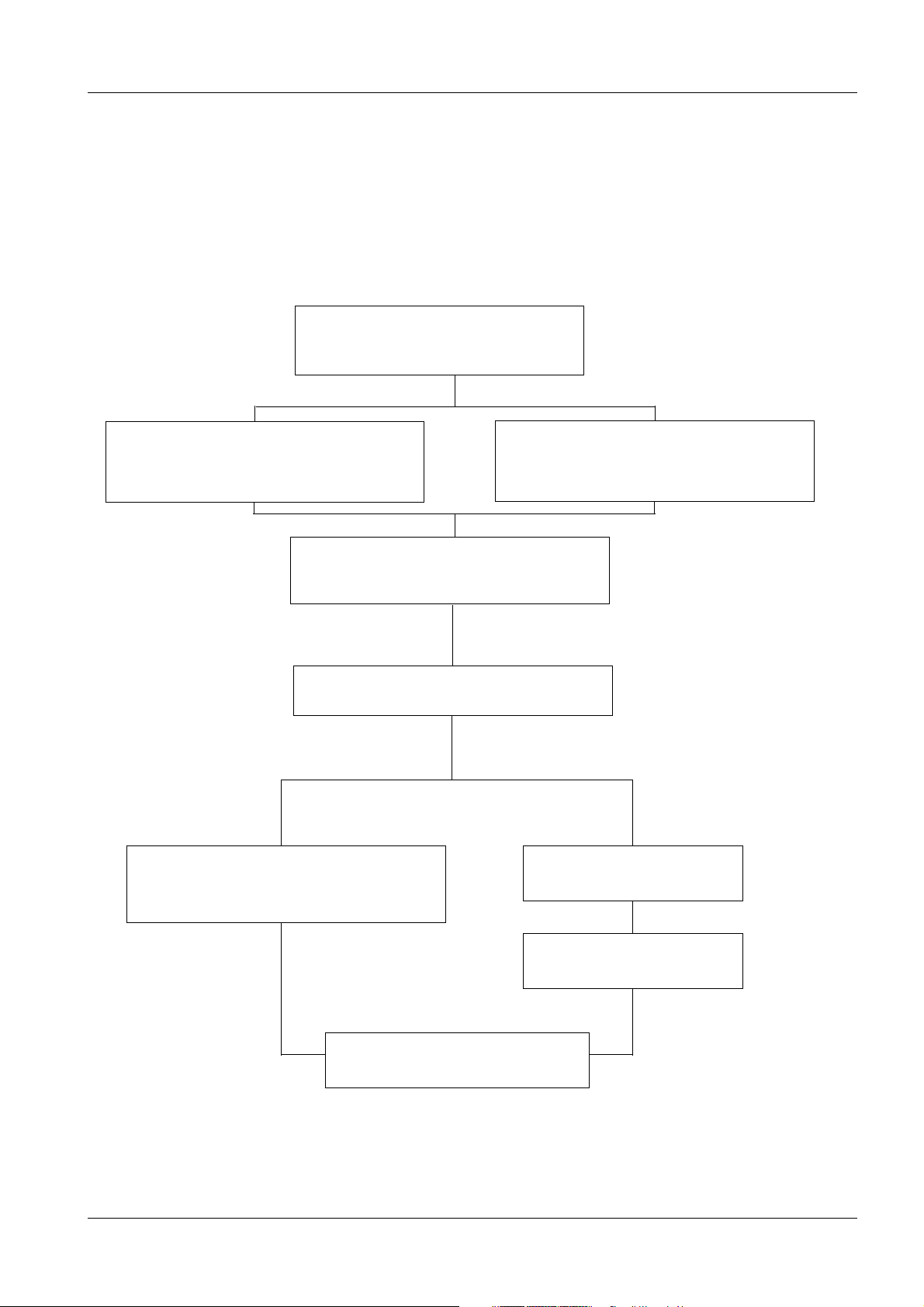
The configuration of the Mammomat installation is dependent on the customer’s choice.
Up to twelve various combinations are possible as shown below:
MAMMOMAT 1000 1
MAMMOMAT 1000 - Basic unit
1 - 1
Molybdenum anode X-ray tube
assembly with filter Mo 0.03
Fixed object-table arm
("Wing 2" no counterweight)
Dose Calculation System
Generator with integrated
control panel and radiation shield
Molybdenum anode X-ray tube
assembly with filter disc
Mo 0.03/Rh 0.025
Separate generator
Separate control console
Free-standing radiation shield
Fig. 1
Siemens AG Register 3 SPB7-230.033.11 Page 1 of 6 M1000/3000 Nova
Medical Solutions Rev. 05 05.05 CS PS 24 Installation and Start-Up
Page 10
1 - 2 Prerequisites
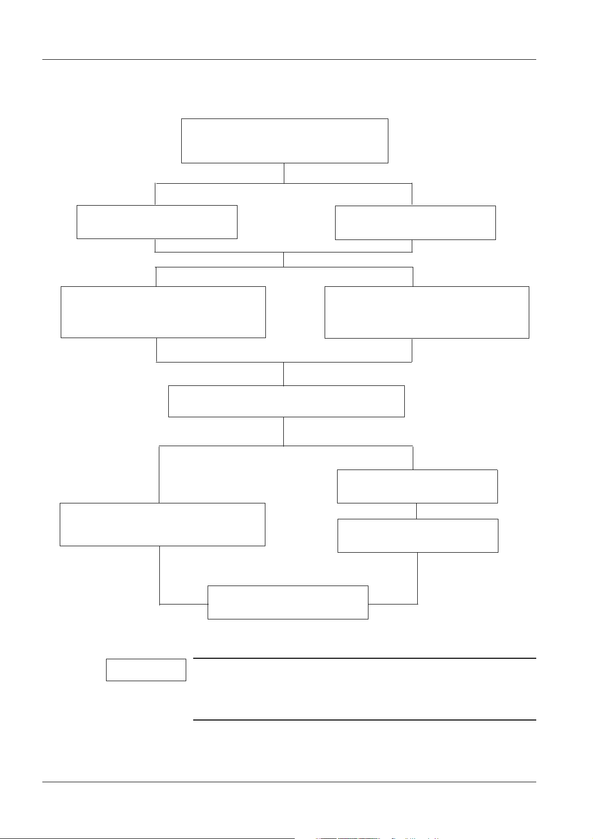
MAMMOMAT 3000 Nova 1
MAMMOMAT 3000 Nova - Basic unit
Pivoting object-table arm
("Wing 1"+ "Wing 2")
Molybdenum/tungsten anode X-ray
tube assembly with filter disc
Mo 0.03/Rh 0.025/Rh 0.050
Dose Calculation System
Fixed object-table arm
("Wing 1" + counterweight)
Molybdenum anode X-ray tube
assembly with filter disc
Mo 0.03/Rh 0.025
Separate generator
Generator with integrated
control panel and radiation shield
Separate control console
Free-standing radiation shield
Fig. 2
NOTE
M1000/3000 Nova Register 3 SPB7-230.033.11 Page 2 of 6 Siemens AG
Installation and Start-Up Rev. 05 05.05 CS PS 24 Medical Solutions
A P40 MoW tube will be delivered irrespective of whether the customer has chosen the molybdenum/tungsten anode X-ray tube or
the molybdenum anode X-ray tube. In the last case, the tungsten
anode is deselected by the software.
Page 11
Prerequisites 1 - 3
Unless otherwise stated, these instructions describe the stand with pivoted object-table
arm and generator with integrated radiation shield and control panel.
Depending on the installation configuration, some points may be omitted.
Meters and appliances, tools 1
Meters and appliances required 1
NOTE
Calibrated instruments are required.
• Power Line Impedance Meter.
• Protective ground-wire tester.
• Oscilloscope, e.g TEKTRONIX 314.
• Digital multimeter (Fluke type 8060A, part no. 97 02 101 Y4290 or Fluke type 87, part no.
97 03 976 Y4290).
• Sensitometer.
• Densitometer e.g PDA 81.
• Service PC with connecting cable (PC-Generator), part no. 99 00 440 RE999.
• Normi 7 test body (provided by the customer) or SIB phantom Type 42 001 (PTW or
INAK).
• Centering cross, part no. 96 60 051 RE 999.
• AEC calibration plexi:
- Three plates, "2" cm (part no. 65 61 232)
- One plate, "1" cm (part no. 65 61 224)
WAR NING
The existing ground conductor in the mains cable must under no
circumstances be disconnected when operating the oscilloscope.
Life-threatening electric shock hazard exist.
For those measurements, in which any resulting ground loop may
falsify the measuring result, use the differential amplifier (difference measurement).
Tools required 1
• Standard installation tool kit.
• Torque wrench for bolting the stand/generator to the floor (optional).
• Electrical screwdriver with adjustable torque is recommended.
• Calculator
This symbol indicates exposure of X-ray radiation.
Siemens AG Register 3 SPB7-230.033.11 Page 3 of 6 M1000/3000 Nova
Medical Solutions Rev. 05 05.05 CS PS 24 Installation and Start-Up
Page 12

1 - 4 Prerequisites
Important notes on start-up 1
The MAMMOMAT is adjusted, programmed and tested in the factory, leaving the adapta-
tion to the on-site mains voltage, adjustment of the AEC and the functional tests to be performed.
When the measurements to be made (kV, mAs, etc.) are within the tolerances stated in
these instructions, this confirms that the settings made in the factory have not changed
and the equipment is fully serviceable.
The measured values marked with in Chapter 10 "Checks with high voltage" shall be
entered in the "start-up" column in the test certificate provided.
The service PC is required only for programming according to:
• Chapter 10 "Checks with high voltage"
• Chapter 11 "Calibrating and adjusting the AEC"
• Chapter 12 "Dose Calculation System"
• Chapter 13 "Testing"
• Chapter 14 "Further programming"
• Chapter 20 "Final procedures"
Description of the service PC syntax is found in Chapter 22 "Appendix".
NOTE
If the generator is switched off with the service PC connected,
wait approximately 5 s before switching it on again.
Checking and recording for the area of application of the X-ray decree (§16 Germany)
In the area of application of the X-ray decree, an acceptance test certificate is supplied,
with most of the data filled in by the factory.
Only:
• the cut-off dose
• the resolution of the film/screen systems used
• the output values of the constancy test
must be determined by the owner of the equipment and recorded in the acceptance test
certificate. Furthermore, the front page of the acceptance test certificate must also be
completed with the operator´s data.
1
M1000/3000 Nova Register 3 SPB7-230.033.11 Page 4 of 6 Siemens AG
Installation and Start-Up Rev. 05 05.05 CS PS 24 Medical Solutions
Page 13

Prerequisites 1 - 5
Checking and recording for the DHHS area of application 1
In the area of application of the DHHS regulations, maintenance measurements must be
made according to the "DHHS Maintenance Instructions" SPB7-230.662.03.04.02 and the
"DHHS Supplements to the instructions for use" SPB7-230.661.02.03.02.
Sections 1
• Required labels.
• Radiation ON indicators.
• Manual termination of exposure.
• Checking the maximum adjustable mAs.
• Filters in beam limiting device (BLD).
• Reproducibility.
• kVp-accuracy.
• mAs-accuracy.
• Automatic exposure control (AEC).
• Coincidence of radiation field/image receptor.
• Alignment of light field/X-ray field.
• Illuminance of light localizer (light field).
• Shut-down of motor-driven compression movement.
The result must be recorded in "DHHS Measurement certificates"
SPB7-230.663.03.03.02.
Some of the values to be determined can be taken from the acceptance test certificate.
The radiation-field limitation is set at the factory and recorded in the acceptance test certif-
icate.
If the measurements to be made concerning the radiation-field limitation are within the tol-
erances stated in these instructions, this confirms that the settings made at the factory
have not changed.
Note on delivery state 1
The MAMMOMAT has been tested and adjusted at the factory, and should therefore be
ready for operation after completion of the installation.
The equipment is set to 400 V, 2-phase, on delivery.
Siemens AG Register 3 SPB7-230.033.11 Page 5 of 6 M1000/3000 Nova
Medical Solutions Rev. 05 05.05 CS PS 24 Installation and Start-Up
Page 14

1 - 6 Prerequisites
This page intentionally left blank.
M1000/3000 Nova Register 3 SPB7-230.033.11 Page 6 of 6 Siemens AG
Installation and Start-Up Rev. 05 05.05 CS PS 24 Medical Solutions
Page 15

Protective measures 2
Protective measures 2
It is very important that any intervention in the equipment will start with disconnecting it
from the power supply with the main circuit-breaker. Before removing or inserting any of
the printed circuit board, switch of the equipment. To prevent accidental triggering of high
voltage and radiation, set the switch S2 (SS) on p.c. board D702 to "OFF" (lower position,
no triggering of the SS relay).
2 - 1
WAR NING
WAR NING
CAUTION
If the system is only switched off at the control panel or with
S2/D711, line voltage will still be present at the generator line connection, line filter Z1, Z2, transformer T1, transformer T10 and p.c.
board D711 (see wiring diagram).
Life-threatening electric shock hazard exists.
Disconnect mains cable and comply with the information on this
page.
After shut-down of the system, there may still be 380 V DC
present on the intermediate circuit.
Life-threatening electric shock hazard exists.
The voltage level will be indicated by LED V24 on PC board D710.
The voltage will drop to less than 30 V within about 3 minutes, the
LED goes out at about 30 V.
The p.c. boards contain electrostatic highly sensitive components.
If not regarded, the components could be damaged.
Use ESD-equipment, ground prior to making contact and place
the components on a conductive surface.
WAR NING
Siemens AG Register 3 SPB7-230.033.11 Page 1 of 2 M1000/3000 Nova
Medical Solutions Rev. 05 05.05 CS PS 24 Installation and Start-Up
The edges of the metal curtain of the stand are very sharp.
They may cause severe injury.
Apply the protective strips as mentioned in section "Protective
strips for the metal curtain" on page 3 - 5 after removing the covers from the stand. Remove the protective strips only when the
covers are to be mounted or when vertical adjustment of the
swivel-arm system is necessary.
Page 16

2 - 2 Protective measures
Delay times between two exposures 2
Delay times listed below must be followed in order to prevent the tube from overheating.
Exposure mAs value Delay time between two exposures (seconds)
max 100 min 15
max 200 min 30
max 300 min 45
max 400 min 60
max 500 min 75
M1000/3000 Nova Register 3 SPB7-230.033.11 Page 2 of 2 Siemens AG
Installation and Start-Up Rev. 05 05.05 CS PS 24 Medical Solutions
Page 17

Preparatory work 3
General 3
Scope of delivery 3
The MAMMOMAT is normally packed in one crate and one cardboard box (the number of
packages is dependent on the customer’s choice, however):
Crate (length 2140 mm, width 800 mm, height 1375 mm)
The crate contains:
• Compression plate
• Stand with X-ray tube assembly and base plate
• Object table 18 cm x 24 cm (Bucky)
• External diaphragm
• Cover panels
• Installation material
• Optional: Stanchions for the lead-glass pane (radiation shield)
3 - 1
• Cable ducts
• Technical documents
Cardboard box (lenght 1210 mm, width 820 mm, height 700 mm)
The cardboard box contains:
• Generator with high-voltage generator and base plate.
• Optional: Lead-glass pane
• Optional: Separate control console
Further accessories are packed in a separate cardboard box.
Unpacking 3
As a general rule, the directional marks on the crates should be observed during transport, storage and unpacking.
The stand crate is bolted together, while the cardboard box is secured with plastic straps.
CAUTION
The unpacking must be carfully performed.
There’s a risk for foot injuries when handling heavy parts.
Wear safety footwear.
Siemens AG Register 3 SPB7-230.033.11 Page 1 of 8 M1000/3000 Nova
Medical Solutions Rev. 05 05.05 CS PS 24 Installation and Start-Up
Page 18
3 - 2 Preparatory work
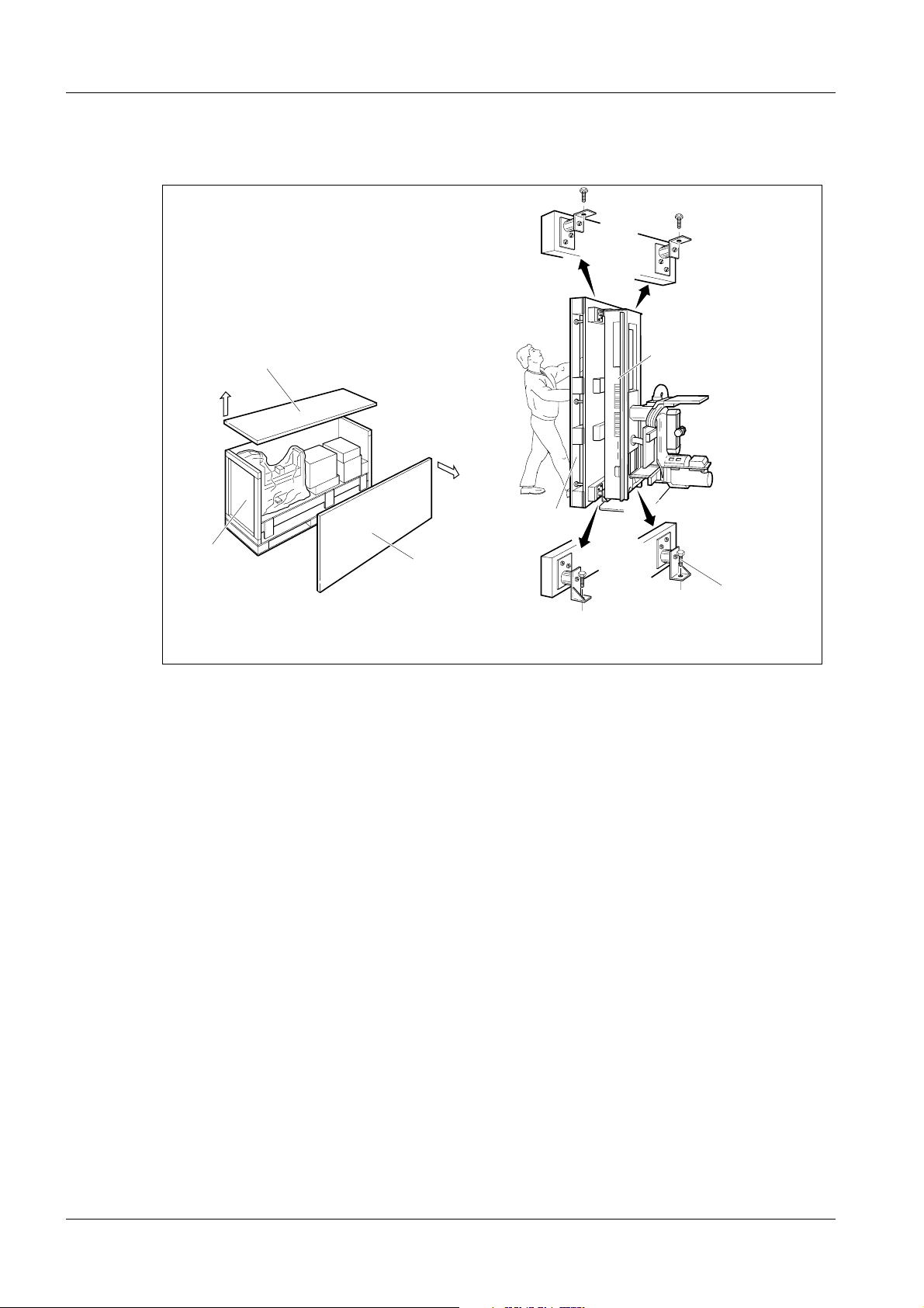
Unpacking the stand 3
1
3
Fig. 1 Unpacking the stand
1
2
5
2
4
6
Unpacking
1. Open the stand crate by removing the top (1) and then the side wall (2).
2. Take out all enclosed packages (accessories, installation material, cover panels
etc.) from the crate.
MAM00167
3. Remove the wooden supports.
4. Remove the remaining walls (3).
5. Upend the stand (4), with pallet (5) (two persons are required).
6. Loosen the four bolts (6) and remove the pallet (5).
M1000/3000 Nova Register 3 SPB7-230.033.11 Page 2 of 8 Siemens AG
Installation and Start-Up Rev. 05 05.05 CS PS 24 Medical Solutions
Page 19
Preparatory work 3 - 3
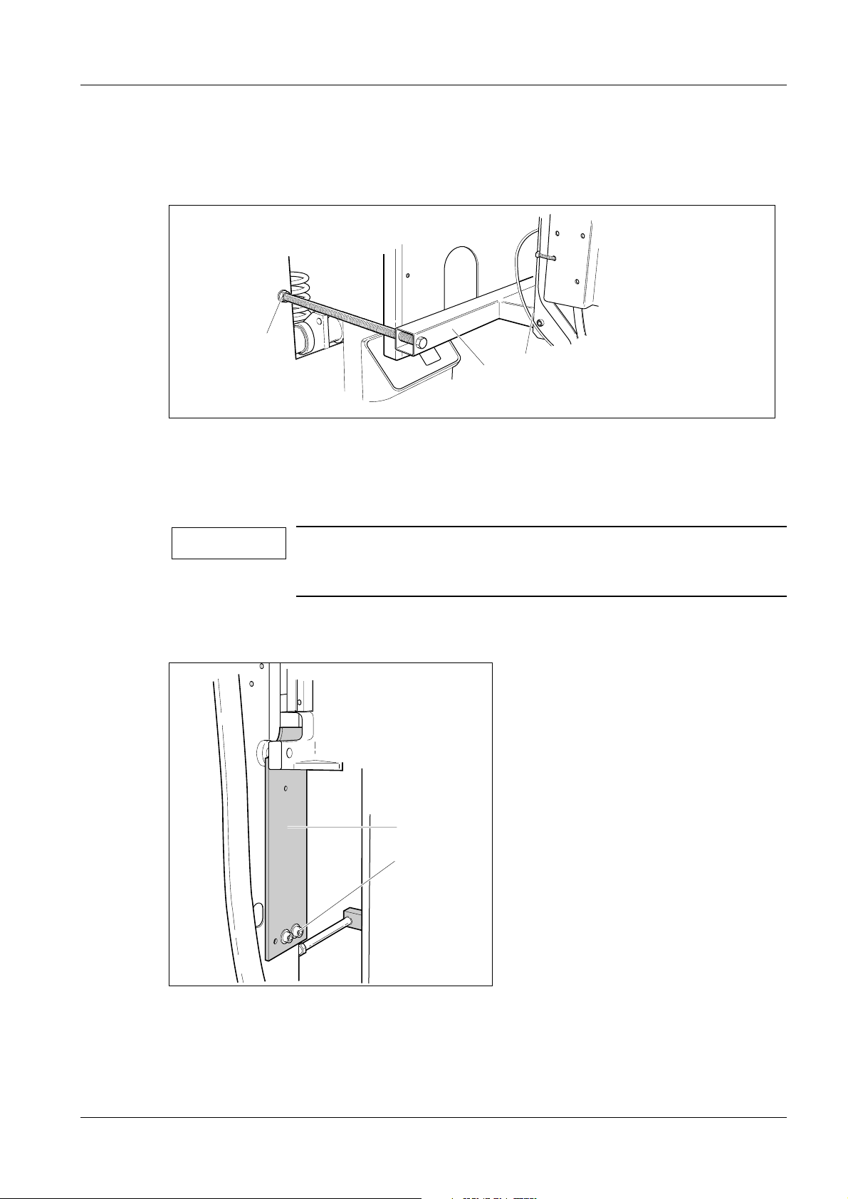
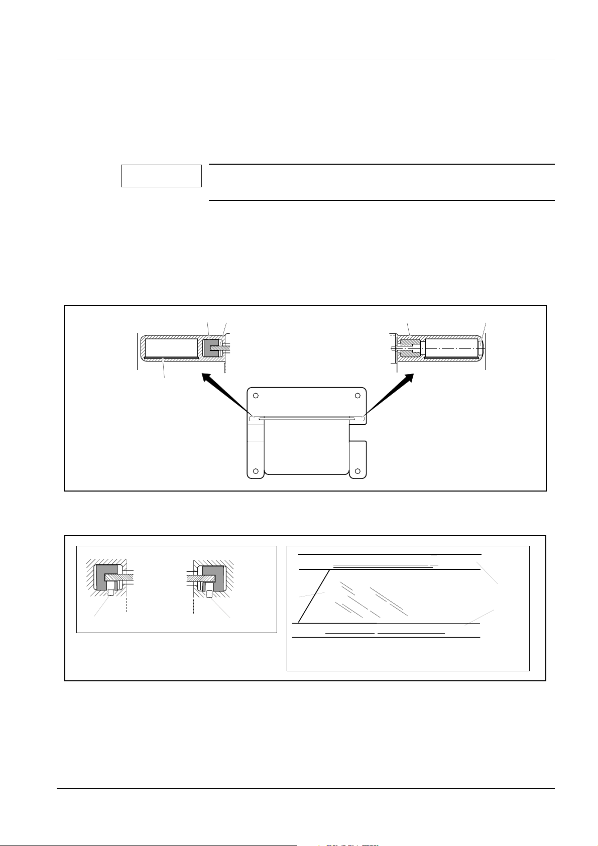
Removing the transport safeguards 3
Removing the swivel-arm system transport safeguard 3
1
2
3
MAM00081
Fig. 2 Swivel-arm system transport safeguard
1. Loosen the transport safeguard nuts (1/Fig. 2) and remove the tube head screws
(2/Fig. 2).
2. Push the red transport safeguard (3/Fig. 2) inwards, away from the tube head.
NOTE
Removal of the swivel-arm system transport safeguard is done
after the equipment has been powered up, see further section
"Attaching the swivel-arm covers" on page 7 - 1.
Transport safeguard for the lifting carriage 3
2
1
MAM00082
Fig. 3 Transport safeguard for the lifting carriage
1. Loosen the two screws (1/Fig. 3) and remove the red transport safeguard (2/Fig.
3). Reinsert screws (1/Fig. 3), they might be needed for service purposes.
Siemens AG Register 3 SPB7-230.033.11 Page 3 of 8 M1000/3000 Nova
Medical Solutions Rev. 05 05.05 CS PS 24 Installation and Start-Up
Page 20
3 - 4 Preparatory work
NOTE
The lifting carriage transport safeguard shall be kept for service
purposes (Fig. 5).
2. Cut and remove the cable tie securing the balancing spring during transport.
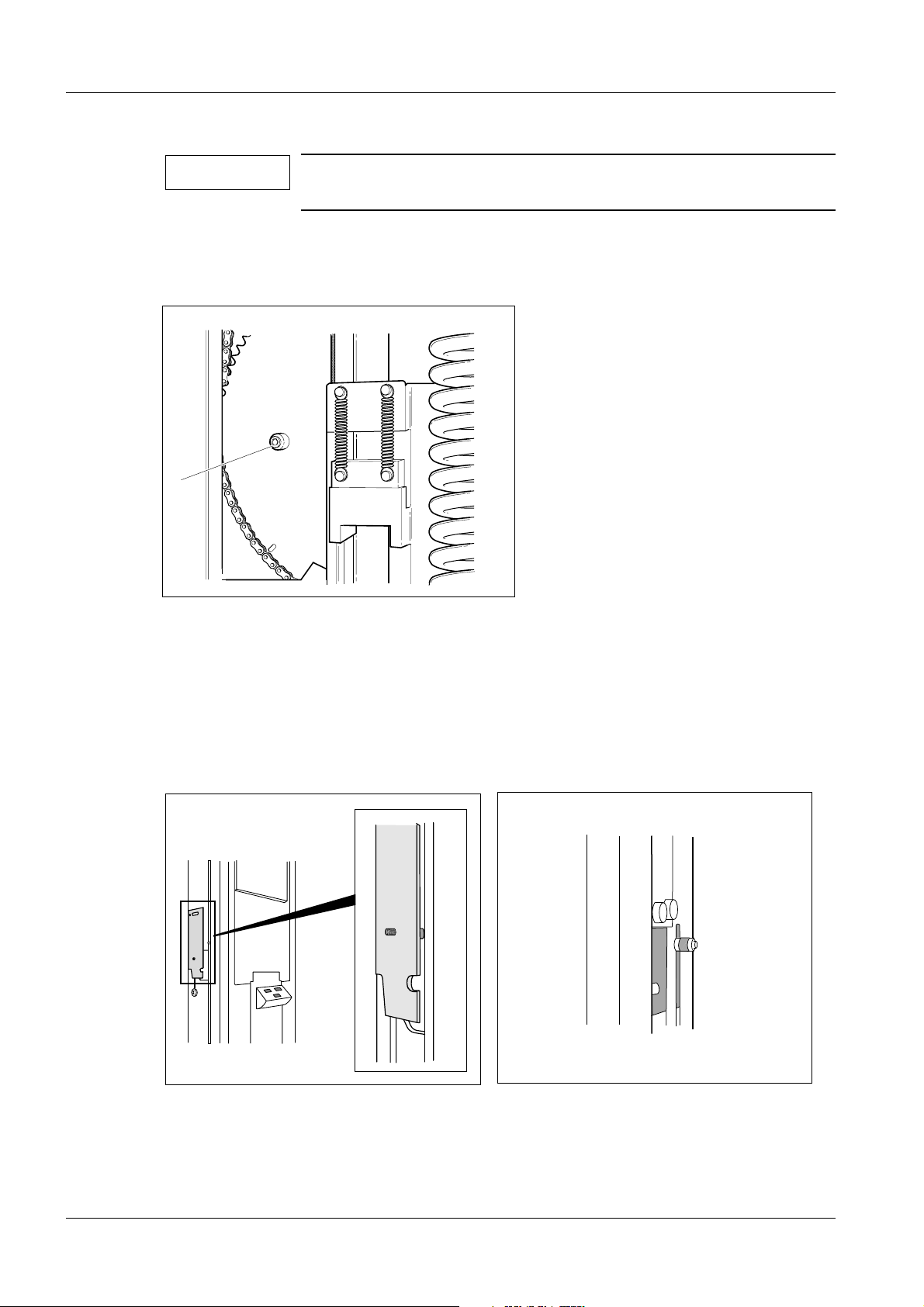
Transport safeguard for the rotary motion 3
1
MAM00083
Fig. 4 Transport safeguard for the rotary motion
1. Remove the transport safeguard screw (1/Fig. 4) with spacer to enable rotary
motion.
The screw and the spacer should be kept for the mounting of the lifting carriage
transport safeguard.
2. Mount the red lifting carriage transport safeguard with screw and spacer
(1/Fig. 4) on the left hand side of the stand, see Fig. 5. Insert the screw through the
slot from the inside of the stand, see Fig. 6
MAM00314
MAM00312
MAM00313
Fig. 5 Transport safeguard mounted on the stand Fig. 6 Screw and spacer inserted from the inside of the
stand
3. Tighten the screw. Make sure that the transport safeguard is parallell to the
stand.
M1000/3000 Nova Register 3 SPB7-230.033.11 Page 4 of 8 Siemens AG
Installation and Start-Up Rev. 05 05.05 CS PS 24 Medical Solutions
Page 21
Preparatory work 3 - 5
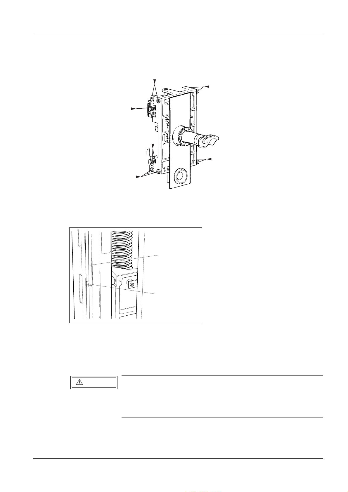
Ball bearings 3
The lifting carriage is equipped with twelve ball bearings (Fig. 7). Check that all twelve ball
bearings are in place and that they show no sign of damage.
Fig. 7 Ball bearings
Protective strips for the metal curtain 3
1
2
MAM00084
Fig. 8 Protective strips for the metal curtain
The edges of the metal curtain are very sharp and are therefore provided with protective
strips (1) on delivery. These strips must always be applied onto the edges of the metal
curtain during service and maintenance work.
CAUTION
Remove the protective strips before performing vertical adjustment of the swivel arm.
If not removed, the protective strips could be damaged.
Make sure the protective strips are removed before adjustments.
Holders (2) for storing the protective strips when not in use, are provided on both sides of
the curtain, see Fig. 8.
Siemens AG Register 3 SPB7-230.033.11 Page 5 of 8 M1000/3000 Nova
Medical Solutions Rev. 05 05.05 CS PS 24 Installation and Start-Up
Page 22
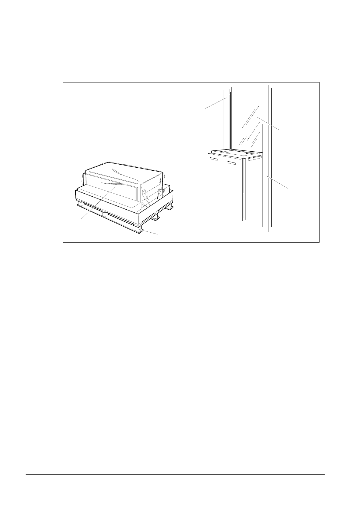
3 - 6 Preparatory work
Unpacking the generator and mounting the radiation shield (optional)
1
3
3
4
3
2
MAM00085
Fig. 9 Unpacking the generator
1. Open the cardboard box by cutting the plastic straps.
2. Lift out the lead-glass and put it away in a safe place.
3. Remove the protective cover from the generator.
4. Upend the generator (1/Fig. 9) and lift it off the pallet (2/Fig. 9) (two persons are
required).
M1000/3000 Nova Register 3 SPB7-230.033.11 Page 6 of 8 Siemens AG
Installation and Start-Up Rev. 05 05.05 CS PS 24 Medical Solutions
Page 23
Preparatory work 3 - 7
Optional:
5. Insert sheet-metal strip (5/Fig. 10) (additional radiation protection) into both
stanchions.
6. Fit the lead-glass (4/Fig. 10) into both vibration absorbing strips (6/Fig. 10) and fix
it softly by screws (1/Fig. 10).
NOTE
The screws must be mounted before the lead-glass is inserted in
the stanchions.
7. Fit the lead-glass (2/Fig. 10) into the groove of one of the stanchions (3 /Fig. 10)
and keep it in position while mounting the other stanchion (3 /Fig. 10).
8. Mount the stanchions and lead-glass unit with 6 screws onto the generator
(3, 4 /Fig. 9) (two persons are required).
9. Cover the holes with plastic caps (7/Fig. 10).
6
5
3
74
Fig. 10
MAM00086
Fig. 10 Mounting the radiation shield
3
2
1
1
MAM00630
3
MAM00633
Siemens AG Register 3 SPB7-230.033.11 Page 7 of 8 M1000/3000 Nova
Medical Solutions Rev. 05 05.05 CS PS 24 Installation and Start-Up
Page 24

3 - 8 Preparatory work
This page intentionally left blank.
M1000/3000 Nova Register 3 SPB7-230.033.11 Page 8 of 8 Siemens AG
Installation and Start-Up Rev. 05 05.05 CS PS 24 Medical Solutions
Page 25
Installing the generator and the stand 4
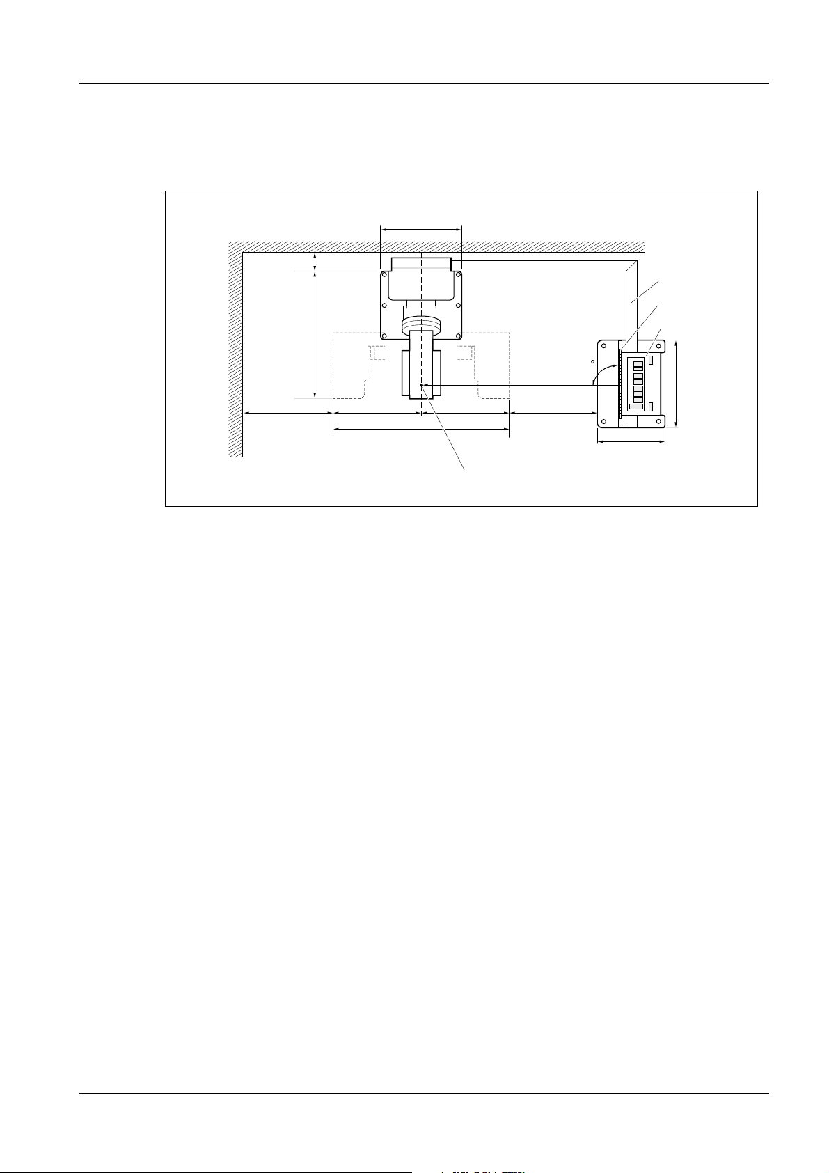
Arranging the components 4
Position the stand and the generator in accordance with installation plan and Fig. 1 below.
640
4 - 1
700
Fig. 1 Installation, top view
180
1091
700 700
1400
4
90
700
540
1
2
3
708
MAM00503
Cable duct (1) and generator (3) with radiation shield (2) can be installed optionally to the
left or to the right of the the stand. The cables can also be laid underfloor. Maximum cable
length between stand and generator is approximately 3.5 m.
Radiation shield (2) at right angles to the swivel-arm system and centered to the focus
mark (4) on the tube-head cover according to Fig. 1.
Recommended minimum distance to wall and generator base plate respectively is
700 mm (shorter distances may be used at the customer´s desire, if in compliance with
local regulations).
For the installation of the cable duct, a minimum distance of 180 mm between wall and
stands is required.
Notes on installations with separate generator and separate control console
- The separate generator can be installed in any suitable place. The maximum distance
of 3.5 m (maximum cable length) to the stand must be maintained, however. If
separately installed, the generator must be bolted to the floor alternatively be attached
to the wall by means of wall brackets, see further Chapter 21 "Bolting the stand/
generator to the floor".
- The separate control console can be installed in a suitable place (wall-mounted or
mounted on a table, for example in an adjacent room with radiation-proof window), or
be mounted onto the free-standing radiation shield (option). The connection cable to
the generator measures 10 m.
4
Siemens AG Register 3 SPB7-230.033.11 Page 1 of 6 M1000/3000 Nova
Medical Solutions Rev. 05 05.05 CS PS 24 Installation and Start-Up
Page 26
4 - 2 Installing the generator and the stand
Free-standing radiation shield (option) 4
For the installation of the free-standing radiation shield, please refer to separate instructions enclosed with the radiation shield.
Removing the generator cover 4
1. Pry loose the plastic strip (1) and remove the sixteen screws (2), eight on each
side.
NOTICE
Pay special attention to the contact washers (there are four contact washers on either side).
They are needed again when reassembling the front cover to
establish protective ground connection and to fulfil EMC (Electro
Magnetic Compatibility) requirements.
2. Remove the front cover (3) from the generator.
2
3
MAM00091
1
Fig. 2 Removing the generator cover
M1000/3000 Nova Register 3 SPB7-230.033.11 Page 2 of 6 Siemens AG
Installation and Start-Up Rev. 05 05.05 CS PS 24 Medical Solutions
Page 27
Installing the generator and the stand 4 - 3
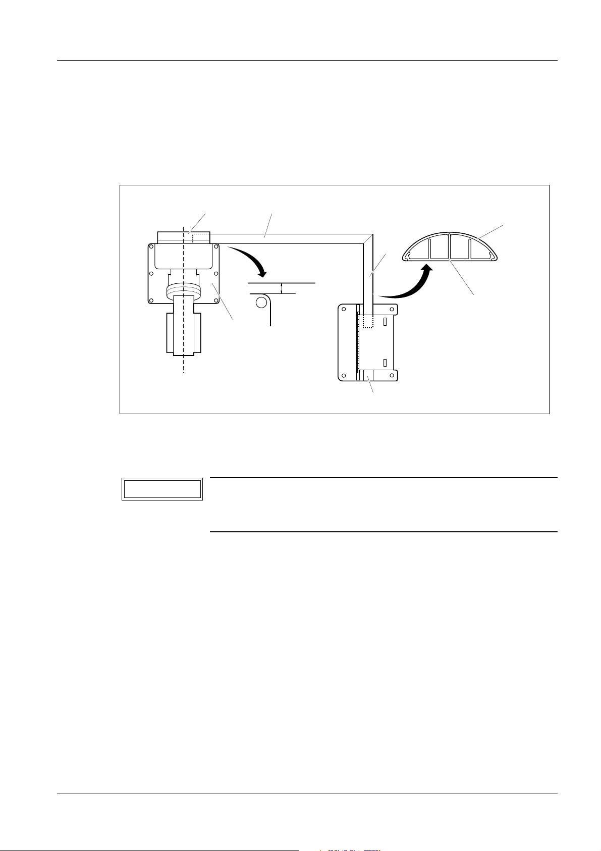
Installing the cable ducts 4
1. Position the cable ducts (1) to the stand and the generator respectively.
2. Leave sufficient space, approx 10 mm between the cable ducts (1) and the base
plate of the stand (3) to allow for the mounting of the cable outlet cover (4).
3. Check that the cable duct (1) is slightly overlapped by the cable outlet cover (4).
4
3
Fig. 3 Installing the cable ducts (top view)
1
1
10 mm
6
7
1. Mark the outlines of the cable ducts (1) on the floor.
2. Cut the bottom of the cable ducts (6) and the cable duct cover (5) to proper length.
NOTICE
Fig. 3 shows a right-angled installation of the cable ducts.
5
MAM00089
If the generator is to be installed at an other angle to the stand,
you just have to cut the cable ducts correspondingly.
3. Fasten the bottom plate of the cable ducts (6) to the floor according to marking,
using double-sided adhesive tape.
4. At the generator, cover the cable entry not used with the enclosed cover plate (7).
Installations with separate control console 4
For the connection cable separate control console – generator, additional cable ducts are
required, unless the cables are to be laid underfloor.
Siemens AG Register 3 SPB7-230.033.11 Page 3 of 6 M1000/3000 Nova
Medical Solutions Rev. 05 05.05 CS PS 24 Installation and Start-Up
Page 28
4 - 4 Installing the generator and the stand
Laying the cable harness 4
NOTE
Remove the transport safeguards which consist of cable ties
(four around the cable harness and one at the end of each
shielded cable).
1. Separate the cable harness.
2. Lay the stand cable harness in the cable duct, as shown in Fig. 4, all the way to the
generator.
3. Fit the cable duct covers (6) onto the cable ducts.
1
2
3
4
MAM00092
5
6
1
2
Fig. 4 Laying the cable harness
The cable harness consists of four shielded cables, see Fig. 4.
Pos in Fig. 4 Description
1 High voltage cable H1
2 AEC signal cables X10 and X11
Unit control cable X1
Power supply cable X14
3 Anode rotation cable X9
Filament cable X8
4 Mains supply cables L1, L2
Protective ground
MAM00215
4
3
5 Decompression-button cable (only with separate control console)
M1000/3000 Nova Register 3 SPB7-230.033.11 Page 4 of 6 Siemens AG
Installation and Start-Up Rev. 05 05.05 CS PS 24 Medical Solutions
Page 29
Installing the generator and the stand 4 - 5
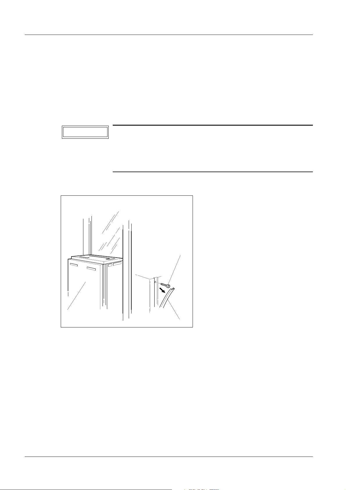
Installations with separate control console 4
Lay the connecting cable from the control console in additional cable ducts, alternatively
underfloor, to the free cable entry of the generator, see further section on page 5 - 8.
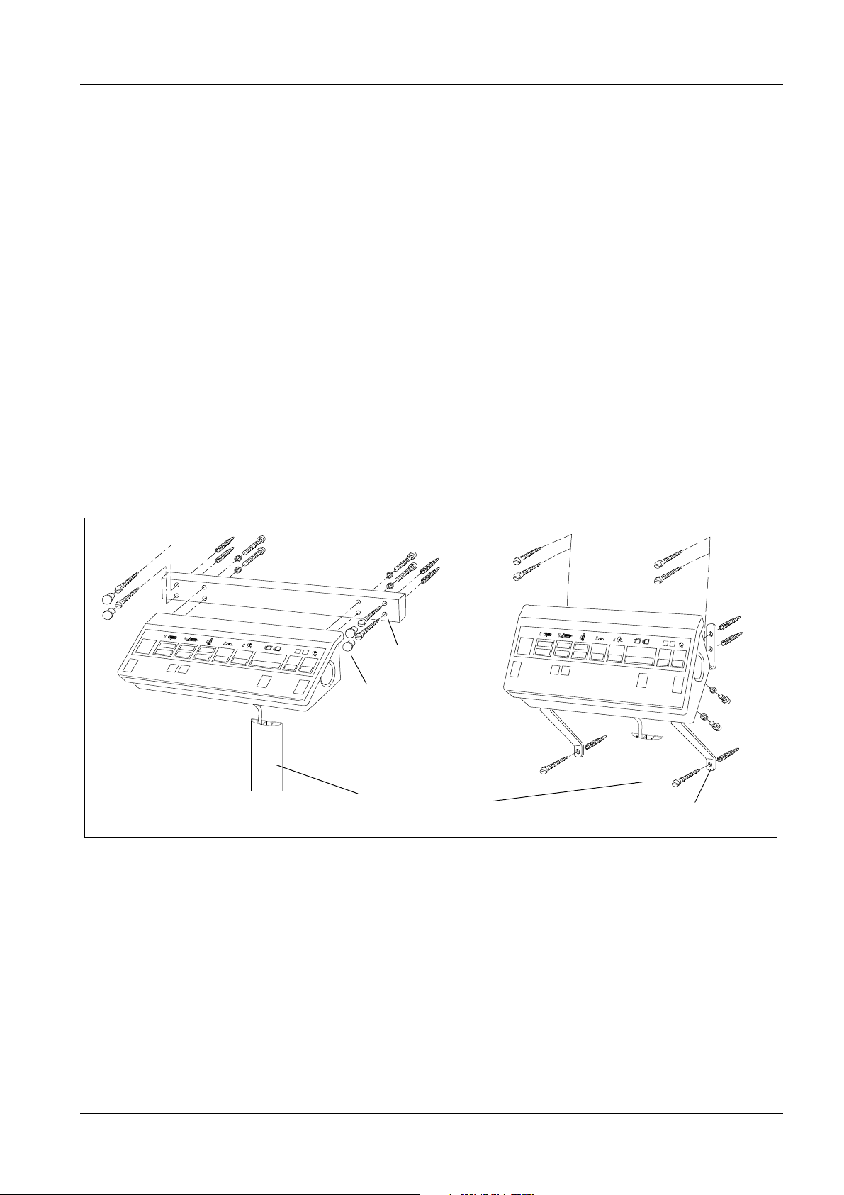
The separate control console can be wall-mounted – horizontally or vertically as shown in
Fig. 5 below – or be mounted on a table, either in the examination room or in an adjacent
room with radiation-proof window. It is important that the control console be placed so that
the operator has good view of the patient from the control console.
Ensure that the control console is attached to the wall with adequate safety margins. Dowels and screws are not supplied. Please obtain these locally and ensure that they are suitable for the material used in the wall. The separate control console has a weight of 4 kg.
There are two cable outlets on the separate control console; one at the back and one on
the underside. On delivery, the cable is led through the outlet at the back of the control
console. For wall-mounted control console, the cable shall be led through the outlet on the
underside.
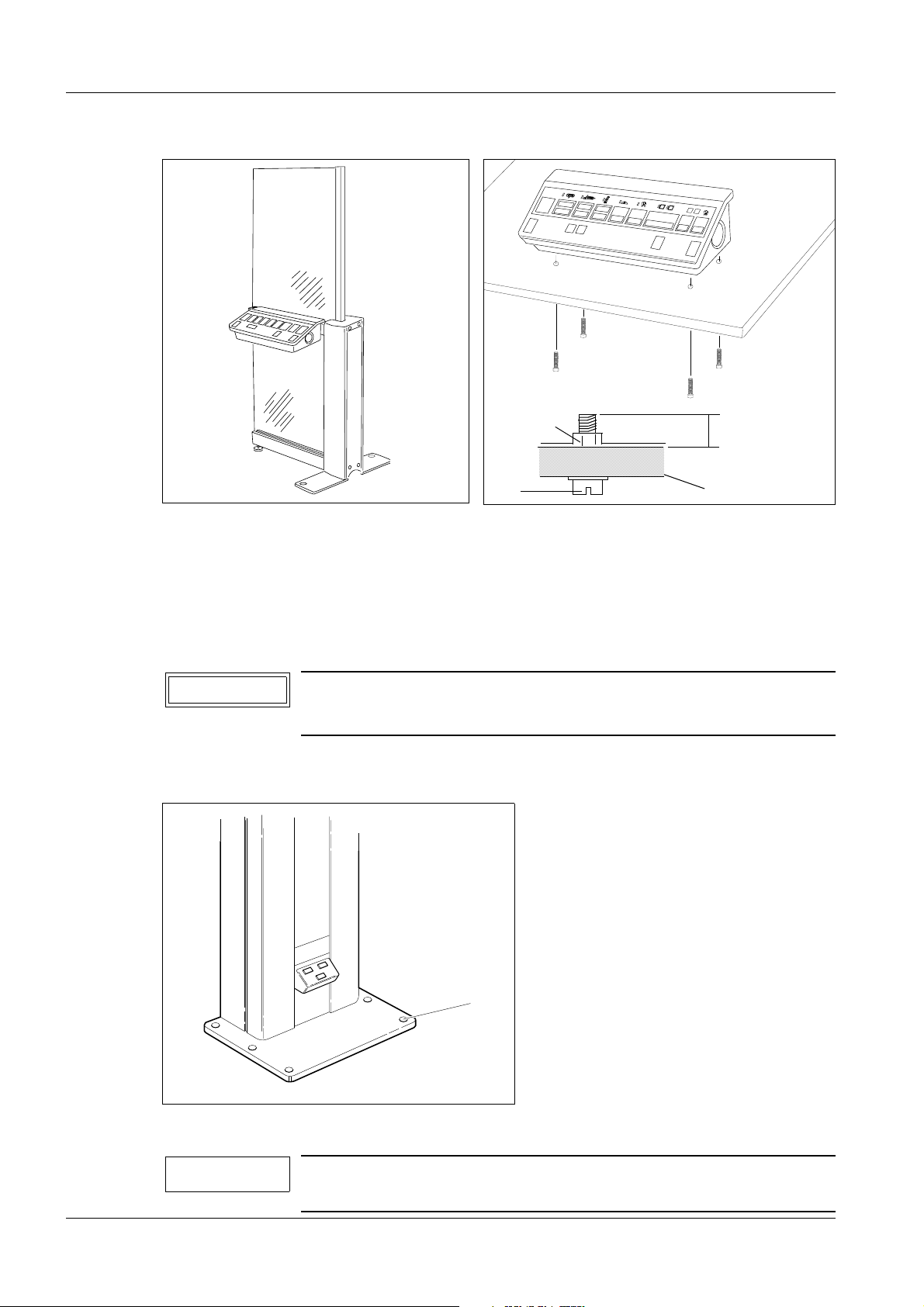
If the control console is to be mounted on a table, the minimum/maximum length of the
screws penetrating into the control console must be observed, see Fig. 7 below.
The control console can also be mounted on the free-standing radiation shield (option) as
shown in Fig. 6 below, see separate instructions enclosed with the radiation shield.
MAM00168
Horizontal mounting
Fig. 5 Wall-mounted control console
∅ 6.5 mm
Plastic cap
Wall-mounted cable duct
is recommended
MAM00169
∅ 6.5 mm
Vertical mounting
Siemens AG Register 3 SPB7-230.033.11 Page 5 of 6 M1000/3000 Nova
Medical Solutions Rev. 05 05.05 CS PS 24 Installation and Start-Up
Page 30
4 - 6 Installing the generator and the stand
MAM00171
<
min. 10 mm –
max. 30 mm
<
Tabl e t op
MAM00170
Fig. 6 Control console on free-standing radiation shield
(option)
Welded nut
M6
Fig. 7 Control console mounted on table
Aligning the stand 4
1. Align the stand vertically by means of the levelling screws (1/Fig. 8).
For adjustment of the levelling screws, use a ratchet spanner 1/2" with extension
(without socket).
NOTICE
2. Cover the levelling screws with the cover discs supplied.
It is important that all six screws bear against the floor.
This is to ensure optimum stability of the stand.
1
MAM00090
Fig. 8 Levelling screws
NOTE
If bolting to the floor is required, please refer to Chapter 21 "Bolting the stand/generator to the floor" on page 21 - 1.
M1000/3000 Nova Register 3 SPB7-230.033.11 Page 6 of 6 Siemens AG
Installation and Start-Up Rev. 05 05.05 CS PS 24 Medical Solutions
Page 31

Cable connections 5
EMC measures 5
The following measures are required to ensure electromagnetic compatibility of the equipment.
EMC measures at the cable entry 5
Fitting the hose clamps and ferrite sleeves 5
3cm
5 - 1
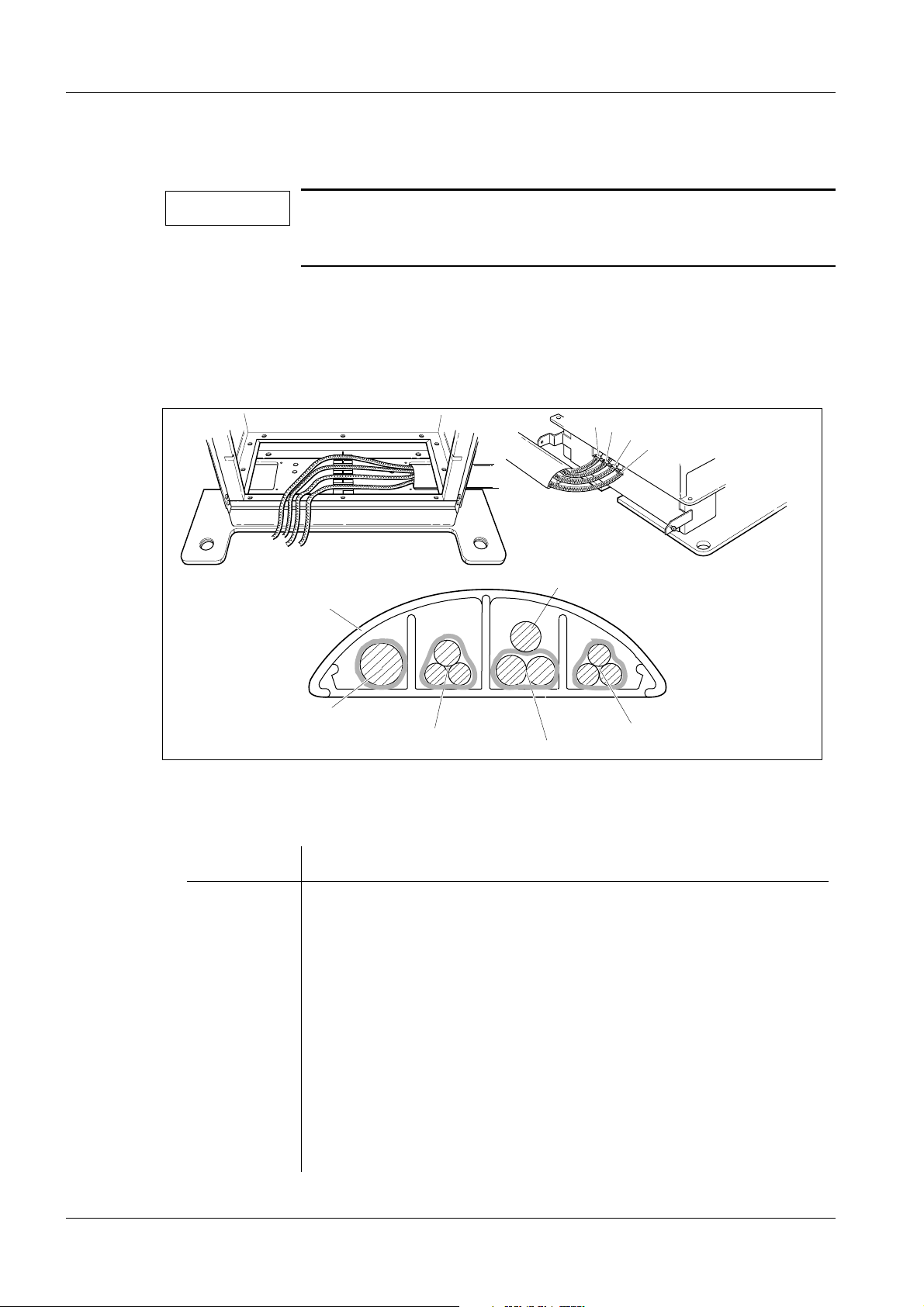
Fig. 1 Cables from the stand
1. Lay the cable harness from the stand to the generator and leave approximately
3 cm of the shielding at the U-bracket, see Fig. 1.
Stow away excessive cable lengths as shown in Fig. 2.
MAM00100
Siemens AG Register 3 SPB7-230.033.11 Page 1 of 14 M1000/3000 Nova
Medical Solutions Rev. 05 05.05 CS PS 24 Installation and Start-Up
Page 32

5 - 2 Cable connections
4
Fig. 2 Ferrite sleeves and hose clamp
3
3
2
2
1
2. Provide each incoming cable with a ferrite sleeve (4), except for mains supply
cables L1 and L2 and the ground wire, which shall be laid together in one and the
same ferrite sleeve. Ferrite sleeves are included in the delivery.
MAM00098
3. Provide each cable with a hose clamp (3). Hose clamps are included in the
delivery.
4. Fold the shield braid (1) backwards over the U-bracket (2) on each cable and
secure with the hose clamp (3).
Note on separate control console and separate generator 5
If the installation includes a separate control console and separate generator, please refer
to page 5 - 8 for information on how to install the additional connection cable between the
control console and the generator.
M1000/3000 Nova Register 3 SPB7-230.033.11 Page 2 of 14 Siemens AG
Installation and Start-Up Rev. 05 05.05 CS PS 24 Medical Solutions
Page 33

Cable connections 5 - 3
EMC measures on the bottom plate 5
Fitting the cables X1, X8 and X9 onto the bottom plate 5
3
Fig. 3 Bottom plate
4
2
1
1. Fit the bottom plate at the bottom of the generator stand as shown in Fig. 3.
2. Carefully cut away the insulation on cables X1, X8 and X9 to lay bare the shield
braid (1).
3. Select proper clamps (2) with regard to the thickness of the cables. Cable clamps
in different sizes are provided on the bottom plate.
4. Fit the clamp (2) over the shield braid and screw tight to ensure satisfactory
contact between shield braid and clamp.
NOTE
Make sure that all excess cable lengths are placed below the bottom plate.
5. Fasten the bottom plate with four screws (3) and contact washers (4).
MAM00099
NOTE
Cable X9 shall also be clamped to the side wall of the cabinet, if
not already done, see Fig. 7 in this chapter.
NOTE
Do not remove insulation and do not ground the shields of the
AEC signal cables to X10 and X11.
Siemens AG Register 3 SPB7-230.033.11 Page 3 of 14 M1000/3000 Nova
Medical Solutions Rev. 05 05.05 CS PS 24 Installation and Start-Up
Page 34

5 - 4 Cable connections
Connecting the stand cable-harness 5
High-voltage connector 5
3
1
2
MAM00161
Fig. 4 High-voltage connector
NOTICE
The high-voltage connector (1) is factory-adjusted for correct fit.
The high-voltage connector shall be inserted with silicone oil, silicone-rubber ring (2) and silicone-rubber disc (3). Lubricate the silicone-rubber disc and the pins with silicon oil before mounting
the disc. Make sure that there aren’t any air bubbles between the
disc and the connector.
M1000/3000 Nova Register 3 SPB7-230.033.11 Page 4 of 14 Siemens AG
Installation and Start-Up Rev. 05 05.05 CS PS 24 Medical Solutions
Page 35

Cable connections 5 - 5
Connecting the high-voltage connector 5
3
2
1
Fig. 5 Connecting the high-voltage connector
4
MAM00162
1. Plug in the high-voltage connector (1) at H1.
2. Tighten the sleeve nut (2) by hand.
3. Tighten the stop screws on the sleeve nut.
4. Position the high-voltage cable (3) to the right in the generator and fasten with
cable ties (4).
Siemens AG Register 3 SPB7-230.033.11 Page 5 of 14 M1000/3000 Nova
Medical Solutions Rev. 05 05.05 CS PS 24 Installation and Start-Up
Page 36

5 - 6 Cable connections
Connecting the cable harness to the generator 5
NOTICE
EMC measures required.
They are described on page 5 - 1 in this chapter.
2
1
6
5
Fig. 6 Cable harness at the generator
F10 F20
F1
F2
F3
F4
F5
3
4
7
MAM00165
MAM00165
Unit control cable X1 5
1. Connect the unit control cable X1 to D700 X1 (1).
Filament cable X8 5
1. Connect the filament cable X8 to D700 X8 (2).
Power supply cable X14 5
1. Connect the power supply cable X14 to D711 X14 (3).
2. Strain-relieve it on the side with a cable tie (4).
AEC signal cable X10 and X11 5
NOTE
1. Connect the AEC signal cable connectors, X10 and X11, to D700 X10 (5) and X11
(6).
The AEC signal cable consists of two cables laid together as one
cable with two connectors labeled X10 and X11 at the end of the
cable.
M1000/3000 Nova Register 3 SPB7-230.033.11 Page 6 of 14 Siemens AG
Installation and Start-Up Rev. 05 05.05 CS PS 24 Medical Solutions
Page 37

Cable connections 5 - 7
Rotating anode cable X9 5
2
4
3
1
MAM00163
Fig. 7 Connecting X9 to the generator
1. Connect the rotating anode cable X9 to D711 X9 (1).
2. Connect the two blue free wires from connector D711 X9 (1) to capacitor C51 (2).
3. Clamp the cable to the chassis with a cable clamp (3).
NOTICE
Obtain proper grounding.
When fitting the cable clamp, ensure satisfactory contact
between shield braid (pos. 4 / Fig. 7) and chassis.
Siemens AG Register 3 SPB7-230.033.11 Page 7 of 14 M1000/3000 Nova
Medical Solutions Rev. 05 05.05 CS PS 24 Installation and Start-Up
Page 38

5 - 8 Cable connections
MAM001 2
Installations with separate control console and separate generator 5
MAM00166
Connection cable from separate control console
Fig. 8 Connection cable from separate control console
NOTICE
Comply with EMC regulations!
The cable must be shielded from the separate control console as
described below.
1. Lay the connection cable from the separate control console in additional cable
ducts, alternatively underfloor, to the free cable entry of the generator, see Fig. 8.
2. Lay the connection cable in a free U-bracket. Fold the shield braid over the
U-bracket and secure with a hose clamp as shown in Fig. 9.
MAM00173
Fig. 9 Shielding the control console cable
M1000/3000 Nova Register 3 SPB7-230.033.11 Page 8 of 14 Siemens AG
Installation and Start-Up Rev. 05 05.05 CS PS 24 Medical Solutions
MAM00172
Page 39

Cable connections 5 - 9
F
3. Shield the control console cable to the bottom plate of the generator as shown in
Fig. 10.
4. Provide the cables with ferrite sleeves. Cables X5 and X32 can be laid together in
one ferrite sleeve, X30 and the decompression-button cable in another sleeve
(two extra ferrite sleeves are included in the delivery). Plug together the
decompression button cables. Shield the decompression button cable to the
bottom plate, see Fig. 10. Lay the decompression button cable in the cable duct,
alter-natively underfloor, to the stand, see Fig. 4 in Chapter 4 "Installing the
generator and the stand".
X5, X32
Ground wire
Fig. 10 Cables from separate control console
X30
Decompression
button cable
5. Connect X5 and X32 to the corresponding sockets on circuit board D700, X30 to
connector T3/X30 at the side of the circuit board chassis. Connect the ground wire
to the protective ground terminal below fuse F10, see Fig. 11.
3
F4
F5
MAM00174
Protective
F10 F20
X32 X5 T3/X30
Fig. 11 Connecting the cables from the separate control console
Siemens AG Register 3 SPB7-230.033.11 Page 9 of 14 M1000/3000 Nova
Medical Solutions Rev. 05 05.05 CS PS 24 Installation and Start-Up
ground
MAM00164
Page 40

5 - 10 Cable connections
6. Shield the decompression button cable to the stand chassis as shown in Fig. 12.
Connect to terminals 2 and 3 in terminal block X803 on the inside of the stand
chassis, see Fig. 12.
Fig. 12 Connecting the decompression button cable at the stand
1
Z801
2
1
23
X880
4
X885
MAM00879
Main voltage connection 5
The equipment has been set to 400 V, 2-phase, in the factory (see test certificate).
Adjustment to the line frequency is not needed. If the mains voltage is not 400 V, 2-phase
at the installation site, a reconnection of the mains is necessary.
Should a reconnection for the mains voltage be necessary, this must be done at transformer T10 as well as p.c. board D711 (insertion or removal of fuses and labeling is specified in the wiring diagram, see Line Input page 5-3).
Change the rated voltage labels to the correct voltage (there are two labels on the generator and one on the stand). Labels are included in the installation material.
NOTE
For more details about changing mains, insertion or removal of
jumpers, fuses, labeling etc., see Wiring Diagram.
M1000/3000 Nova Register 3 SPB7-230.033.11 Page 10 of 14 Siemens AG
Installation and Start-Up Rev. 05 05.05 CS PS 24 Medical Solutions
Page 41

Cable connections 5 - 11
Connecting the incoming mains to the stand (400 V, 2-phase) 5
400 V 2-phase connection 5
N
L1
L2
L3
1
2
1
1
4
3
1
Fig. 13 Incoming mains cable
1. Connect the incoming mains cable (1) to X899 (2) in the stand as shown in Fig. 13
and Fig. 14.
2. Fit plastic tubes (4) on the plates.
3. Strain-relieve (3) the incoming mains cable.
TWO-PHASE
GENERATOR STAND
F10
F20
X881
Incoming mains
208, 230, 240, 277 or 400 VAC
P.EN L1L2L3
X899
MAM00097
MAM00095
Fig. 14 Incoming mains, 2-phase
Siemens AG Register 3 SPB7-230.033.11 Page 11 of 14 M1000/3000 Nova
Medical Solutions Rev. 05 05.05 CS PS 24 Installation and Start-Up
Page 42

5 - 12 Cable connections
Connecting the mains supply to the generator (400 V, 2-phase) 5
F1
Fig. 15 Mains supply to the generator
F10 F20
F2
F3
F4
F5
2
1
3
MAM00176
1. Check that there is no wire jumper at F20 (1) and no brass plug at F5 (2).
Fuses must be inserted into fuse holders F20 and F5.
2. Connect the mains supply cables between stand and generator to fuses F10 and
F20 on the generator.
Wire marked L1 to F10 and L2/N to F20.
3. Connect the protective ground wire from the stand to the generator (3).
M1000/3000 Nova Register 3 SPB7-230.033.11 Page 12 of 14 Siemens AG
Installation and Start-Up Rev. 05 05.05 CS PS 24 Medical Solutions
Page 43

Cable connections 5 - 13
Measures for changing from 2-phase to 1-phase connection 5
SINGLE PHASE
GENERATOR STAND
F10
X881
Fig. 16 Incoming mains, 1-phase
Incoming mains
110, 208, 230, 240 or 277 VAC
P.EN L1L2L3
X899
MAM00096
1. Move wire marked N/L2 from X899 L2 to X899 N (stand).
2. Connect incoming phase of the power supply to L1 and the neutral conductor of
the power supply (0 V) to N and fuse F20.
3. Strain-relieve the incoming mains cable as shown in Fig. 13.
4. Short circuit F20 (1) and F5 (2) in Fig. 15 with the jumper and brass plug included
in the service bag.
CAUTION
For single-phase mains connection, make sure that the neutral
conductor of the power supply (0V) is connected to terminal N
and fuse F20.
NOTE
Connections on transformer T10 must be adapted to the actual
mains voltage, see Wiring Diagram for details.
5. Connect the mains supply cable between stand and generator to fuses F10 and
F20 on the generator. Wire marked L1 to F10 and L2/N to F20.
Siemens AG Register 3 SPB7-230.033.11 Page 13 of 14 M1000/3000 Nova
Medical Solutions Rev. 05 05.05 CS PS 24 Installation and Start-Up
Page 44

5 - 14 Cable connections
This page intentionally left blank.
M1000/3000 Nova Register 3 SPB7-230.033.11 Page 14 of 14 Siemens AG
Installation and Start-Up Rev. 05 05.05 CS PS 24 Medical Solutions
Page 45

Mains connection and power supply 6
Checks before powering up the generator 6
On P.C. board D702:
1. Set switch S1(UZW) to "OFF" (lower position).
2. Set switch S2 (SS) to "OFF" (lower position).
6 - 1
ZBL
AR
KVE
BRAKE
STATUS
UZW
SS
TEST
V6
V7
V1
V2
V3
V4
V5
VH
NSE1
NSE2
DS
SS
BS
GND
X990
X967
X980
X981
X982
X983
X984
X985
S1
S2
S3
J39
X962
X964
X960
R13
R11
R43
J50
X965
X961
X963
IHREG
MAREG
X966
X968
X969
X702
MAM00106
Fig. 1 P.C. board D702
Measuring the line resistance 6
See Fig. 2.
1. Remove fuses F10 (1) and F20 (2) or, when single-phase supply, fuse F10 (1).
2. Connect line resistance meter to fuse holders F10 and F20.
3. Mains supply "ON".
4. Carry out measurement.
5. Mains supply "OFF".
Siemens AG Register 3 SPB7-230.033.11 Page 1 of 4 M1000/3000 Nova
Medical Solutions Rev. 05 05.05 CS PS 24 Installation and Start-Up
Page 46

6 - 2 Mains connection and power supply
To achieve the full output, the resistance measured must not exceed the following values:
• 0.25 c at 110 V (1-phase)
• 0.45 c at 208 V
• 0.50 c at 230 V
• 0.60 c at 240 V
• 0.65 c at 277 V
• 0.85 c at 400 V (2-phase)
If the above values are exceeded, reduce the generator power in accordance to
Chapter 14 "Further programming" in this manual.
Checking the line voltage in the generator 6
1. If not already done, remove fuses F10 (1) and F20 (2) or, when single-phase
supply, fuse F10 (1).
4
5
6
1
2
3
Fig. 2 Line voltage in the generator
2. Mains supply "ON".
3. Measure the voltage at fuse holders F10 (1) and F20 (2).
4. Check that the mains voltage agrees with the voltage plugged on transformer T10
(3) and P.C. board D711 (4), located above line filter Z1 (5).
5. Mains supply "OFF".
MAM00177
6. Reinsert fuses F10 (1) and F20 (2).
7. Mains supply "ON" (Do not switch the system on yet).
8. Measure the voltage at transformer T1 (6) terminals 1 and 3, transformer T1 is
located under the line filter Z1 (5). There must be 195 V- 253 V between the
terminals.
9. Measure the voltage at the output of line filter Z1 it must lie within 195 V- 264 V.
M1000/3000 Nova Register 3 SPB7-230.033.11 Page 2 of 4 Siemens AG
Installation and Start-Up Rev. 05 05.05 CS PS 24 Medical Solutions
Page 47

Mains connection and power supply 6 - 3
Checking the supply voltages 6
The correct supply voltages +5 V, +15 V and +24 V have already been tested in the factory. Only a visual check of the function is therefore needed.
1. System "ON".
2. Check that the following orange diodes are "ON" on p.c. board D704:
V39 (+15 V)
V38 (-15 V)
V41 (+5 V)
V40 (+24 V)
Siemens AG Register 3 SPB7-230.033.11 Page 3 of 4 M1000/3000 Nova
Medical Solutions Rev. 05 05.05 CS PS 24 Installation and Start-Up
Page 48

6 - 4 Mains connection and power supply
This page intentionally left blank.
M1000/3000 Nova Register 3 SPB7-230.033.11 Page 4 of 4 Siemens AG
Installation and Start-Up Rev. 05 05.05 CS PS 24 Medical Solutions
Page 49

Attaching the swivel-arm covers 7
Attaching the swivel-arm covers 7
Arranging the swivel-arm system 7
1. Install object table, no compression force (swivel-arm system still upside down).
2. Remove the protective strips from the metal curtain.
3. Run the lifting carriage upwards.
4. Put back the protective strips onto the metal curtain.
5. Rotate the swivel-arm system to 0 degrees by pressing one of the switches for
clockwise rotation on the supporting arm.
6. System and mains "OFF".
7. Remove the swivel-arm system transport safeguard, see Chapter 3
"Preparatory work".
Connecting the cables to control-button boards and patient handles 7
MAMMOMAT 1000/3000 Nova
4
2
1
3
7 - 1
2
Fig. 1 Connecting the cables
Before installing the side covers, the cables are to be connected.
1. Connect cables X807 (1) to control-button circuit boards D807 (2).
2. Connect ground wires (3) to patient handles (4).
1
4
3
MAM00108
Siemens AG Register 3 SPB7-230.033.11 Page 1 of 2 M1000/3000 Nova
Medical Solutions Rev. 05 05.05 CS PS 24 Installation and Start-Up
Page 50

7 - 2 Attaching the swivel-arm covers
Attaching the side covers 7
Screws in different sizes are included in the delivery.
5
4
Fig. 2 Covers and sign
2
1
1. Mount the side covers (1) with six screws (2) on each side.
NOTE
Do not forget to fit the sign (3) when mounting the side covers.
Use the two longer screws.
3
MAM00700
Attaching the front cover 7
CAUTION
1. The side covers must be flush at the front. If necessary, loosen the screws and
adjust the side covers.
2. Carefully fit the front cover (4) so that both openings engage with the lugs of the
side covers.
3. Carefully swing the front cover upwards and let it snap in position over the side
covers.
CAUTION
4. Fasten the front cover to the side covers with two short screws (5).
Risk of damages.
If the covers are exposed to internal stress cracks might arise.
The following work must be carried out with caution.
The front cover must not press against the collimator.
Risk of damage.
Be careful while attaching the front cover.
M1000/3000 Nova Register 3 SPB7-230.033.11 Page 2 of 2 Siemens AG
Installation and Start-Up Rev. 05 05.05 CS PS 24 Medical Solutions
Page 51

Checking the microprocessors 8
Microprocessors 8
The following LED displays on the processor P.C. boards indicate whether the relevant
microprocessors are operating correctly.
1. Mains and system "ON".
The following conditions must be indicated after not more than 15 s.
8 - 1
Microprocessors for:
AEC: P.c. board D701
Master: P.c. board D702
P.C. board D711:
• V9 "ON" (line voltage on).
• V13 "OFF" (system stand-by).
• V11 "ON" (system on).
• V16 "ON" (intermediate circuit - filament).
LED displays
Must be off.
Steadily on.
Must be steadily
on or off.
Must be off.
Flashing rapidly.
MAM00649
Siemens AG Register 3 SPB7-230.033.11 Page 1 of 2 M1000/3000 Nova
Medical Solutions Rev. 05 05.05 CS PS 24 Installation and Start-Up
Page 52

8 - 2 Checking the microprocessors
This page intentionally left blank.
M1000/3000 Nova Register 3 SPB7-230.033.11 Page 2 of 2 Siemens AG
Installation and Start-Up Rev. 05 05.05 CS PS 24 Medical Solutions
Page 53

Checks without high voltage 9
Checks without high voltage 9
1. System "OFF".
2. On P.C. board D702 set switch S1 (UZW) to "ON" (upper position) and switch S2
(SS) to "OFF" (lower position).
3. System "ON".
4. Insert a cassette.
5. Set 27 kV and maximum mAs on the control panel.
9 - 1
NOTE
6. Press the exposure buttons on the control panel. The rotating anode shall start up.
At the end of the time limit, the rotating anode is braked.
7. Release the exposure buttons.
8. System "OFF".
The cassette must be removed and reinserted after each
exposure to allow for the next exposure release. This is to avoid
double exposures.
Siemens AG Register 3 SPB7-230.033.11 Page 1 of 2 M1000/3000 Nova
Medical Solutions Rev. 05 05.05 CS PS 24 Installation and Start-Up
Page 54

9 - 2 Checks without high voltage
This page intentionally left blank.
M1000/3000 Nova Register 3 SPB7-230.033.11 Page 2 of 2 Siemens AG
Installation and Start-Up Rev. 05 05.05 CS PS 24 Medical Solutions
Page 55

Checks with high voltage 10
Preparation 10
This section describes how to check:
• High voltage.
• Tube current.
• mAs values.
10 - 1
NOTE
kV>17
kV>50
WR_AUS
MASOLL
MAIST
IHSOLL
IHIST
UZIST
ISCHWING
KVSOLL
KVIST
0VA
KVE
KVA
ZBL
BRAKE
0VD
V39
V41
V40
Check that the high-voltage plug is plugged into H1 and properly
secured.
X706
X707
X705
X704
X713
X710
X712
X711
X708
X714
X715
X716
X717
X709
R136
X703
MAM00111
Fig. 1 P.C. board D705
1. Set switch S2 (SS) to "ON" (upper position) on P.C. board D702.
2. Remove the jumper and connect the mAs meter to mAs measuring sockets X3
and X4 on P.C. board D710.
Siemens AG Register 3 SPB7-230.033.11 Page 1 of 10 M1000/3000 Nova
Medical Solutions Rev. 05 05.05 CS PS 24 Installation and Start-Up
Page 56

10 - 2 Checks with high voltage
3. Connect oscilloscope to P.C. board D705 as follows:
• Channel 1 to measuring point "KVIST (actual value)" (1 V= 5 kV).
• Channel 2 to measuring point "MAIST (actual value)" (1 V= 40 mA).
• Trigger at measuring point "KVE" (start with high voltage "ON"), rising edge.
• Twist the measuring leads and connect their grounding braids to measuring
point "0 VA".
4. Connect service PC to circuit board D702 using the connection cable.
5. Start the Service Program, see Chapter 22 "Appendix".
6. Check the anode menu for correct selection (tungsten anode enabled or disabled,
depending on which type of X-ray tube the customer has chosen). See Service
Program Instructions SPB7-230.114.03. ... .
NOTE
It is possible to select tungsten anode, even if the customer does
not have this option. However, the 50 µm Rh filter will then be
missing.
kV-adjustment 10
Check the kV as follows:
1. Mains voltage and system OFF.
WAR NING
2. Connect DVM between the lower ends of R72 and R73 (on the left side of the high
tension plug) on D710 circuit board.
3. Mains voltage and system ON.
4. Set 27 kV and maximum mAs on the control panel.
After shut-down of the system, there may still be 380 V DC present
on the intermediate circuit.
Life-threatening electric shock hazard exists.
The voltage level will be indicated by LED V24 on PC board D710.
The voltage will drop to less than 30 V within about 3 minutes, the
LED goes out at about 30 V.
5. Make an exposure and check that the DVM shows +2.700 V +0.010 V. Note the
values in the kV-adjustment protocol on page 22 - 6.
M1000/3000 Nova Register 3 SPB7-230.033.11 Page 2 of 10 Siemens AG
Installation and Start-Up Rev. 05 05.05 CS PS 24 Medical Solutions
Page 57

Checks with high voltage 10 - 3
6. If necessary, adjust R43 on D702 (Fig. 2) and make another exposure. Note the
new values in the kV-adjustment protocol.
NOTE
Decrease
kV
Potentiometer
R43
Fig. 2
Do not overload the X-ray tube by making too many exposures in a
Increase
kV
short time.
R43 does not need to be relocked with locking paint.
7. Mains and system OFF.
8. Disconnect DVM from R72 and R73.
MAM00528
Siemens AG Register 3 SPB7-230.033.11 Page 3 of 10 M1000/3000 Nova
Medical Solutions Rev. 05 05.05 CS PS 24 Installation and Start-Up
Page 58

10 - 4 Checks with high voltage
Filament 10
1. In <Mainmenu> select <Configuration> and <Filament>.
2. Perform Learn filament for available options.
3. Note the new values in the Test protocol (Filament).
NOTE
Only settings for Mo available for M1000.
M1000/3000 Nova Register 3 SPB7-230.033.11 Page 4 of 10 Siemens AG
Installation and Start-Up Rev. 05 05.05 CS PS 24 Medical Solutions
Page 59

Checks with high voltage 10 - 5
Checking X-ray tube high voltage, tube current and mAs values 10
1. System "ON".
2. Set the "cassette loaded" switch to "OFF" with the Service Program:
Configuration - Miscellaneous - Cassette loaded check.
3. Trigger test exposures with the following exposure values and check the kV
values and tube current characteristic on the oscilloscope (see oscillograms).
The accuracy of the kV is &5% plus &1.5 kV during the first 5 ms of the exposure.
For mA values < 50 mA, the accuracy of the kV is &5% plus &2 kV during the first
5ms.
The tube current must rise quickly to the set value at the beginning of the exposure and run linearly during the exposure.
The accuracy of the mAs product must be &10%.
4. Replace the jumper previously removed from sockets X3 and X4 on P.C. board
D710.
Siemens AG Register 3 SPB7-230.033.11 Page 5 of 10 M1000/3000 Nova
Medical Solutions Rev. 05 05.05 CS PS 24 Installation and Start-Up
Page 60

10 - 6 Checks with high voltage
Oscilloscope diagrams 10
• MAMMOMAT in mAs mode, see Fig. 3 - Fig. 10.
NOTE
Tube P40 MoW,
MAMMOMAT 3000 Nova
* tungsten anode 0.3
30 kV 20 mAs (P = 4.7 kW)
Checks indicated by
filter disc Mo 0.03 / Rh 0.025 (molybdenum rotating anode).
Tube P40 MoW,
MAMMOMAT 1000/3000 Nova
molybdenum anode 0.3
"
MAM00179
Fig. 3 Fig. 4
* shall be disregarded in installations with
30 kV 20 mAs (P = 3.75 kW)
"
MAM00112
30 kV 1 V/T (1 T <=> 5 kV) 30 kV 1 V/T (1 T <=> 5 kV)
158 mA 1 V/T (1 T <=> 40 mA) 125 mA 1 V/T (1 T <=> 40 mA)
127 ms 20 ms/T 160 ms 20 ms/T
NOTE
Record the measured kV and mAs value in the Test protocol, page
22 - 10.
M1000/3000 Nova Register 3 SPB7-230.033.11 Page 6 of 10 Siemens AG
Installation and Start-Up Rev. 05 05.05 CS PS 24 Medical Solutions
Page 61

Checks with high voltage 10 - 7
Tube P40 MoW,
MAMMOMAT 3000 Nova
* tungsten anode 0.3
35 kV 100 mAs (P = 4.7 kW)
MAM00180
Fig. 5 Fig. 6
Tube P40 MoW,
MAMMOMAT 1000/3000 Nova
molybdenum anode 0.3
35 kV 100 mAs(P = 3.75 kW)
35 kV 1 V/T (1 T <=> 5 kV) 35 kV 1 V/T (1 T <=> 5 kV)
134 mA 1 V/T (1 T <=> 40 mA) 107 mA 1 V/T (1 T <=> 40 mA)
0.75 s 0.2 s/T 0.93 s 0.2 s/T
MAM00113
25 kV 100 mAs (P = 4.7 kW)
MAM00181
Fig. 7 Fig. 8
25 kV 100 mAs(P = 3.75 kW)
25 kV 1 V/T (1 T <=>5 kV) 25 kV 1 V/T (1 T <=> 5 kV)
188 mA 2 V/T (1 T <=> 80 mA) 150 mA 2 V/T (1 T <=> 80 mA)
0.53 s 0.1 s/T 0.67 s 0.1 s/T
MAM00114
Siemens AG Register 3 SPB7-230.033.11 Page 7 of 10 M1000/3000 Nova
Medical Solutions Rev. 05 05.05 CS PS 24 Installation and Start-Up
Page 62

10 - 8 Checks with high voltage
Tube P40 MoW,
MAMMOMAT 3000 Nova
* tungsten anode 0.15
30 kV 10 mAs (P = 0.85 kW)
Tube P40 MoW,
MAMMOMAT 1000/3000 Nova
molybdenum anode 0.15
30 kV 10 mAs (P = 0.70 kW)
"
MAM00182
Fig. 9 Fig. 10
30 kV 1 V/T (1 T <=> 5 kV) 30 kV 1 V/T (1 T <=> 5 kV)
28 mA 0.5 V/T (1 T = 20 mA) 23 mA 0.5 V/T (1 T <=> 20 mA)
>>
"
MAM00115
360 ms 50 ms/T 430 ms 100 ms/T
NOTE
NOTE
Small focus is selected by attaching a magnification table.
Record the measured kV and mAs value in the test protocol, page
22 - 10.
M1000/3000 Nova Register 3 SPB7-230.033.11 Page 8 of 10 Siemens AG
Installation and Start-Up Rev. 05 05.05 CS PS 24 Medical Solutions
Page 63

Checks with high voltage 10 - 9
NOTE
Tube P40 MoW,
MAMMOMAT 3000 Nova
* tungsten anode 0.3
30 kV AEC
40 mm plexiglass
Fig. 11 Fig. 12
Measurements in AEC mode shall be performed after calibrating
and adjusting the AEC.
Tube P40 MoW,
MAMMOMAT 1000/3000 Nova
molybdenum anode 0.3
(P = 4.7 kW)
40 mm plexiglass
MAM00666
30 kV
AEC
(P = 3.75 kW)
MAM00667
30 kV 1 V/T (1 T <=> 5 kV) 30 kV 1 V/T (1 T <=> 5 kV)
158 mA 1 V/T (1 T <=> 40 mA) 125 mA 1 V/T (1 T <=> 40 A)
*) 100 ms/T) *) 100 ms/T
*) total exposure time dependent on programmed sensitivity
Siemens AG Register 3 SPB7-230.033.11 Page 9 of 10 M1000/3000 Nova
Medical Solutions Rev. 05 05.05 CS PS 24 Installation and Start-Up
Page 64

10 - 10 Checks with high voltage
This page intentionally left blank.
M1000/3000 Nova Register 3 SPB7-230.033.11 Page 10 of 10 Siemens AG
Installation and Start-Up Rev. 05 05.05 CS PS 24 Medical Solutions
Page 65

Calibrating and adjusting the AEC 11
11 - 1
NOTE
Check that all object tables do not have AEC grids.
If they have AEC grids remove the grid bars according to
"Installation Instructions object tables" RXB7-120.031.06..., which
is delivered with each object table.
Checking and programming with the service PC 11
Use the service PC to check and program the AEC.
Operation of the service PC is described in Chapter 22 "Appendix".
The AEC is based on correction tables. The tables are optimized for the following film/
screen combinations.
The tolerances of the AEC are specified for incremental gamma e 5.
Table 1 Correction table identifications
Film Screen Cassette Sensitivity Mo/Mo Mo/Rh W/Rh
Kodak
Min-R 2000
Kodak
Min-R 2000
Kodak
Min-R 2000
Kodak
2190
Kodak
Min-R 2
Kodak
Min-R 2
0 1004 1005 1006
0 1004 1005 1006
Kodak
Min-R EV
Kodak
Min-R EV
Kodak
Min-R EV
AGFA HDR AGFA HD S AGFA
AGFA HDR C AGFA HD S AGFA
AGFA HDR C
Plus
Fuji
AD-M
Fuji
AD-M
Fuji
UM-MA HC
Kodak
EV 150
Kodak
EV 190
Kodak
EV 250
AGFA HD S AGFA
Fuji
AD Medium
Fuji
AD Mammo
Fine
Fuji
UM Mammo
Medium
Kodak
Min-R 2
Kodak
Min-R 2
Kodak
Min-R 2
Mammoray
Mammoray
Mammoray
Fuji
AD-MA
Fuji
AD-MA 0 1004 1005 1006
Fuji
AD-MA 0 1104 1105 1106
0 1004 1005 1006
0 1004 1005 1006
0 1004 1005 1006
0 1004 1005 1006
0 1004 1005 1006
0 1004 1005 1006
0 1201 1202 1203
Fuji
UM-MA HC
Siemens AG Register 3 SPB7-230.033.11 Page 1 of 22 M1000/3000 Nova
Medical Solutions Rev. 05 05.05 CS PS 24 Installation and Start-Up
Fuji
UM Mammo
Fine
Fuji
AD-MA 0 1104 1105 1106
Page 66

11 - 2 Calibrating and adjusting the AEC
For Sterling, the correction table for Kodak Min-R 2000 is recommended.
The indications of this table are meant as recommendations. In case of failure the calibra-
tion of AEC with other series of correction tables may be attempted.
NOTE
If the film/screen combination in question is not listed in Table 1,
the correction tables for one of the listed combinations will have to
be used, although the tolerances for OD variation then cannot be
guaranteed.
Primarily, use the correction tables for Kodak Min-R 2000 if the
film/screen in question is a Kodak etc.
M1000/3000 Nova Register 3 SPB7-230.033.11 Page 2 of 22 Siemens AG
Installation and Start-Up Rev. 05 05.05 CS PS 24 Medical Solutions
Page 67

Calibrating and adjusting the AEC 11 - 3
Preparation of backup floppy 11
1. On the service PC choose DOS prompt. Create the new directory AEC_inst:
C:\>mkdir AEC_inst
2. Change the working directory to the above:
C:\>cd AEC_inst
3. Copy the service PC floppy to C:
C:\AEC_inst> copy a:*.*
4. Copy the floppy AEC correction tables to C:
C:\AEC_inst> copy a:*.*
5. Mark the empty backup floppy with version of service program and insert in
drive A.
6. Copy the contents of AEC_inst to A:
C:\AEC_inst> copy *.* a:
Use this floppy for the remainder of the installation.
Siemens AG Register 3 SPB7-230.033.11 Page 3 of 22 M1000/3000 Nova
Medical Solutions Rev. 05 05.05 CS PS 24 Installation and Start-Up
Page 68

11 - 4 Calibrating and adjusting the AEC
Offset compensation 11
NOTE
Make sure that the "cassette loaded" switch is in position "OFF".
MAMMOMAT equipped with tungsten anode and:
• One wing: three exposures each are to be made with Mo/Mo and W/Rh set
• Two wings: three exposures with Mo/Mo set on Wing 1 and three exposures with W/Rh
set on Wing 2
MAMMOMAT without tungsten anode and with:
• One wing: three exposures with Mo/Mo
• Two wings: three exposures with Mo/Mo set on Wing 1 and three exposures with Mo/Mo
set on Wing 2
1. Make sure the backup floppy is inserted (not write protected).
2. Use an object table with grid.
3. Place a metal plate (part no. 65 52 728) in the cassette opening of the object table,
covering the AEC detector.
4. Place the detector in chestwall position.
5. In <Mainmenu> select <Service> and <Offset compensation test>.
Test offset compensation
Prevent radiation on the detector by placing
a protective material in the path of the beam
Start a test by pressing F3
Test condition: 40 <= Doserate <= 62
<ESC> to exit
1 Help 2 3 5 678910Quit
Fig. 1 Service Program menu, Test offset compensation
dialog
Exp support
MAM00763
M1000/3000 Nova Register 3 SPB7-230.033.11 Page 4 of 22 Siemens AG
Installation and Start-Up Rev. 05 05.05 CS PS 24 Medical Solutions
Page 69

Calibrating and adjusting the AEC 11 - 5
Error message
If the menu "Dos critical error" would appear during the installation, always press "F"
(for fail) and check that the correct floppy is inserted, and is not write protected.
[DOS Critical Error]
[Abort]
[Retry] [Ignore] [Fail]
MAM00735
6. Press <F3> and follow the instructions in the dialogs for exposure.
NOTICE
If Er 02X occurs:
Exit the offset compensation test in the Service Program by
pressing Esc. Acknowledge the error by pressing the limit button.
Wait until the green lamp on the control panel is lit. In <Mainmenu>
select <Service> and <Offset compensation test> and continue the
test.
NOTE
Make sure that the correct anode/filter combination and wing are
selected, according to the list of alternatives at the top of this
page.
7. The measured dose rate will be displayed on the screen. If the result is OK go on
with step 8. If not OK, check that the detector is not mechanically grounded and
repeat the test.
8. Make two more exposures with the same Anode/Filter combination, by repeating
steps 6 and 7.
9. Repeat steps 6 to 8 until all exposure alternatives, as listed above, are covered.
10. Remove metal plate (part no. 65 52 728).
11. Exit the offset compensation test in service PC by pressing Esc.
Siemens AG Register 3 SPB7-230.033.11 Page 5 of 22 M1000/3000 Nova
Medical Solutions Rev. 05 05.05 CS PS 24 Installation and Start-Up
Page 70

11 - 6 Calibrating and adjusting the AEC
Configuration of the AEC 11
Definitions 11
Object table group 11
An object table group contains all object tables of the same type. There are four groups of
object tables - Grid, No grid, Magnification and Stereo. For example the object table group
Grid, consists of Grid 18x24 and Grid 24x30.
General conditions 11
When performing the settings in this chapter, there are some general conditions valid for
all settings:
• The detector is to be in chestwall position.
MAM00616
• The AEC calibration plexi must extend at least 10 mm beyond the chestwall edge of the
table and be centered, see Fig. 2, Page 11 - 8. Place the AEC calibration plexi in the
same position for all exposures.
Calibration conditions 11
Compression plate must not be used during the calibration of correction tables. From the
point sensitivity correction (fine setting) and further on, a compression plate may be used.
Reference cassette 11
Every MAMMOMAT should have a reference cassette. Use this reference cassette where
required and for the settings in this chapter. If there is no dedicated reference cassette,
pick one cassette, mark it and use it for the settings in this chapter.
Film 11
When calibrating the wings and the correction tables, it is possible to use the same film for
each exposure. However, when setting the sensitivity, the operator needs to check the
optical density and the film must be exchanged and developed between every exposure.
Mains voltage 11
Unless otherwise stated, the mains voltage and system must be ON and the service PC
program running, before performing any setting in this chapter.
Sensitivity conditions 11
• One step (1/8 E.P.) corresponds to approximately 0.06 O.D. with an incremental gamma
of 5.
• Measure the optical density on the emulsion side of the film.
M1000/3000 Nova Register 3 SPB7-230.033.11 Page 6 of 22 Siemens AG
Installation and Start-Up Rev. 05 05.05 CS PS 24 Medical Solutions
Page 71

Calibrating and adjusting the AEC 11 - 7
Correction of the measured Optical Density (O.D.) 11
Due to variations in the developing conditions (see also section "Normal developing conditions") the measured optical density of one specific image might not correspond to the
adjusted optical density (sensitivity setting). Therefore the optical density has to be corrected for the variations in the developing conditions.
NOTE
This correction has to be made for
1. fine setting of sensitivity correction
2. setting of sensitivity
3. final testing.
OD
m
The measured optical density in the measuring point, see Fig. 2.
OD
OD
corr
strip
The corrected optical density.
The O.D. in the step of the sensitometer
strip closest to the O.D. of the measuring
point.
OD
strip_ref
The measured OD
on first film exposed
strip
under normal developing conditions shall
be used as OD
strip_ref
.
Procedure 11
• - For grid/no grid: cover the area far from the chestwall side with metal plate (part no.
65 52 728).
- For magnification: place metal plate (part no. 65 61 026) inside the magnification table
as close as possible to the cassette to prevent scattered radiation and cover the area far
from the chestwall side.
• Develop all films with a sensitometer strip on the part that was covered by the metal plate
(part no. 65 52 728 or 65 61 062).
• Measure the optical density in two places: OD
(as described in Fig. 2) and OD
m
strip
(on
the sensitometer strip).
• Calculate the corrected O.D. as follows:
OD
= ODm + (OD
corr
strip_ref
- OD
strip
)
Normal developing conditions 11
When measuring the O.D., it is essential that the working conditions are as close to normal as possible. There are several parameters that may effect the results:
• Temperature of developer and dryer
• Feeding and developing speed
• Replenishing speed of developer and fixer (liquids)
If possible, develop the film among other films when the developer is warm and stabilized.
Siemens AG Register 3 SPB7-230.033.11 Page 7 of 22 M1000/3000 Nova
Medical Solutions Rev. 05 05.05 CS PS 24 Installation and Start-Up
Page 72

11 - 8 Calibrating and adjusting the AEC
Object table
Sensitometer strip
AEC calibration plexi
Film
Measuring
point O.D.
Fig. 2 Position of AEC calibration plexi and film
approx
20 mm
approx
25 mm
Metal plate
part no. 65 52 728
Minimum projecting
Length: 10 mm
*Applicable on condition that the detector is placed in chest-wall position.
M1000/3000 Nova Register 3 SPB7-230.033.11 Page 8 of 22 Siemens AG
Installation and Start-Up Rev. 05 05.05 CS PS 24 Medical Solutions
Page 73

Calibrating and adjusting the AEC 11 - 9
Incremental gamma 11
Incremental gamma is defined as the slope of the gamma curve in the density region of
interest.
On the sensitometer strip it means that:
Incremental gamma = (blackening on the step closest above density region of interest blackening on the step closest below that step) / 0.15.
Step above
Density region
of interest
Step below
Optical density
4
3
Density region
2
of interest
1
0
0
1 3 5 7 9 111315171921
11 12
Sensitometer step numbers
Step above
Step below
MAM00531
Siemens AG Register 3 SPB7-230.033.11 Page 9 of 22 M1000/3000 Nova
Medical Solutions Rev. 05 05.05 CS PS 24 Installation and Start-Up
Page 74

11 - 10 Calibrating and adjusting the AEC
Overview of work routine 11
Main menu
Configuration
Service
Normal mode
Test DUEP Communic.
Backup
Quit
1. "AEC Correction tables" on Page 11 - 11.
Configuration
System type
Anode
Show configuration file
Save configuration file
AEC
Miscellaneous
Filament
AEC
Reset installation parameters
Detector normalization
AEC Correction tables
Sensitivity correction
Copy H to D
Copy D to H
Sensitivity
MAM00611
2. "Sensitivity correction (fine setting)" on Page 11 - 20.
3. "Sensitivity" on Page 11 - 21.
4. "Copy H to D" on Page 11 - 22.
M1000/3000 Nova Register 3 SPB7-230.033.11 Page 10 of 22 Siemens AG
Installation and Start-Up Rev. 05 05.05 CS PS 24 Medical Solutions
Page 75

Calibrating and adjusting the AEC 11 - 11
AEC Correction tables 11
This section will guide you through the following steps:
• Installation of correction tables (F2).
• Calibration of correction tables (F3), including rough setting of sensitivity correction.
The AEC uses one correction table for each Anode/Filter/Speed combination.
Each correction table has separate corrections for each object table group (Magnification,
Grid, No grid and Stereo).
NOTICE
For exact positioning of the needle, the anode/filter combination
"Mo/Mo" or "Mo/Rh" must be used. Therefore, calibration does not
have to be attempted for W/Rh combination in stereo mode.
DLF switch off 11
Deactivate the DLF switch. In <Main menu> select <Configuration>, <Miscellaneous> and
<DLF switch>, press space to set switch to OFF. Press <F2> to save.
Increase grid speed 11
Increase the grid speed. In <Main menu> select <Configuration> and <Grid speed>.
Set the following values:
Grid
Grid fast speed time 1500
Grid fast speed 90
Grid slow speed 30
<ESC> to exit, <TAB> move to next entry field
1 Help 2 Save 3 45678910Quit
ms (2.5 s max)
% of max
% of max
MAM00761
Siemens AG Register 3 SPB7-230.033.11 Page 11 of 22 M1000/3000 Nova
Medical Solutions Rev. 05 05.05 CS PS 24 Installation and Start-Up
Page 76

11 - 12 Calibrating and adjusting the AEC
Installation of AEC correction tables 11
1. In <Mainmenu> select <Configuration>, <AEC> and <AEC correction tables>.
Fig. 3
The dashes in the ID column show that no correction table is installed (
AEC correction tables
Existing tables in the AEC:
Anode/Filter Speed ID Calibrated
Mag Grid No grid Stereo
Mo/Mo H ---- --- --- --- --Mo/Mo D ---- --- --- --- --Mo/Rh H ---- --- --- --- --Mo/Rh D ---- --- --- --- --W/Rh H ---- --- --- --- --W/Rh D ---- --- --- --- ---
).
<ESC> to exit, <F2> to install new table, <F3> to calibrate existing
1 Help 2 Inst Cal3 45678910Quit
Fig. 3 AEC correction tables
NOTE
If only one film/screen combination is to be used install
correction tables for H only.
2. Make sure the backup floppy is inserted.
3. Decide for which combination you need to install correction table. (For available
identifications for correction tables, see Table 1 on Page 11-1 or the backup
floppy.)
4. Place the cursor by one of the desired Anode/Filter/Speed combinations.
Press <F2>.
Install new table
New ID: 0000
MAM00599
<F2> to continue, <ESC> to exit
M1000/3000 Nova Register 3 SPB7-230.033.11 Page 12 of 22 Siemens AG
Installation and Start-Up Rev. 05 05.05 CS PS 24 Medical Solutions
MAM00600
Page 77

Calibrating and adjusting the AEC 11 - 13
5. Type the ID number of the new correction table (see Table 1 on Page 11-1) in the
dialog which appears. Press <F2> to install the table. A message box will appear
before the correction file has been found.
Searching for correction file...
MAM00736
Installing correction table
ID: 1104 for Mo/Mo H
29% done
MAM00729
6. When the transaction of tables is finished, a dialog like Fig. 4, Page 11 - 15 will
appear. To complete the calibration, proceed from step 5 of that section.
NOTICE
In order to resume calibrating after having quit the
program:
Follow the instructions from step number 1 under
"Calibrate correction tables" on Page 11 - 14.
Siemens AG Register 3 SPB7-230.033.11 Page 13 of 22 M1000/3000 Nova
Medical Solutions Rev. 05 05.05 CS PS 24 Installation and Start-Up
Page 78

11 - 14 Calibrating and adjusting the AEC
Calibrate correction tables 11
NOTE
Make sure the backup floppy is inserted.
The Anode/Filter/Speed combinations should be calibrated one at a time.
1. In <Mainmenu> select <Configuration>, <AEC> and <AEC correction tables>.
AEC correction tables
Existing tables in the AEC:
Anode/Filter Speed ID Calibrated
Mag Grid No grid Stereo
Mo/Mo H 1104 No No No No
Mo/Mo D ---- --- --- --- --Mo/Rh H 1105 No No No No
Mo/Rh D ---- --- --- --- --W/Rh H 1106 No No No No
W/Rh D ---- --- --- --- ---
<ESC> to exit, <F2> to install new table, <F3> to calibrate existing
1 Help 2 Inst Cal3 45678910Quit
MAM00730
NOTICE
The dose monitoring function is only enabled if the applicable
combination is calibrated.
All object table groups and Anode/Filter combinations available
at the site must be calibrated prior to release for clinical use.
However, calibration does not have to be attempted for W/Rh
combination in stereo mode.
2. Place the marker by one of the desired Anode/Filter/Speed combinations. Press
<F3> to transfer the table.
3. This message box is displayed while the service PC receives the correction table.
Receiving correction table
for Mo/Mo H
63% done
MAM00602
M1000/3000 Nova Register 3 SPB7-230.033.11 Page 14 of 22 Siemens AG
Installation and Start-Up Rev. 05 05.05 CS PS 24 Medical Solutions
Page 79

Calibrating and adjusting the AEC 11 - 15
4. When the transfer is done, the dialog Calibration AEC correction table appears.
Calibration AEC correction table
Mo/Mo H, Table ID: 1104
Object table group
Magnification Not calibrated
Grid Not calibrated
No grid Not calibrated
Stereo Not calibrated
<ESC> to exit, <F2> to save, <F3> to calibrate, <F4> to clear calibration
1 Help 2 Save Cal3 45678910Quit
Fig. 4 Dialog Calibration AEC correction table shows which object tables, in the current Anode/Filter/Speed
Clear
MAM00731
5. To calibrate the correction table for an object table group, place the cursor in front
of the group. Press <F3>.
Please mount a
grid table
and press <ENTER> to continue
or <ESC> to cancel.
MAM00608
NOTE
<ENTER> - ok / <ESC> - cancel
Calibration of correction tables for Stereo is to be done
with Stereo angle 0i and with cassette in one of the end
positions of the object table.
6. Follow the instructions in the message box above and press <ENTER>.
Sensitivity correction
Used: 0
New: 0
<F2> save, <F3> exp support, <F4> continue, <ESC> exit
Fig. 5 Dialog Sensitivity correction
Siemens AG Register 3 SPB7-230.033.11 Page 15 of 22 M1000/3000 Nova
Medical Solutions Rev. 05 05.05 CS PS 24 Installation and Start-Up
MAM00764
Page 80

11 - 16 Calibrating and adjusting the AEC
7. Before calibrating the installed correction tables, it is necessary to make a rough
setting of the sensitivity correction for the chosen object table group. Insert the
reference cassette, with a new film, in the object table.
8.
NOTE
NOTE
Make sure the backup floppy is inserted.
Do not use a compression plate.
Press <F3>.
Please put x cm of Plexi
on the object table.
Perform an exposure and
press <ENTER> when ready
or <ESC> to cancel.
<ENTER> - ok / <ESC> - cancel
MAM00728
9. Follow the instructions in the message box for performing an exposure.
10. Remove the exposed film, make a sensitometer strip and develop the film.
11. Measure O.D. in the measuring point (Fig. 2, Page 11 - 8) as well as OD
sensitometer strip (OD
If it is the very first exposed film, use OD
and OD
m
strip
).
strip
as OD
strip_ref
.
strip
Correct the value according to "Correction of the measured Optical Density
(O.D.)" on Page 11 - 7.
on the
12. If the value differs from 1.5 O.D. adjust the values in dialog AEC - Sensitivity
correction (Fig. 5), save the new Sensitivity correction value with <F2> and repeat
the procedures described from step 7.
If the value is satisfactory, proceed by pressing <F4>.
NOTE
One adjustment step of sensitivity correction (1/8 E.P.)
corresponds to approximately 0.06 O.D. with an
incremental gamma of 5.
NOTE
It is important to use 1.5 O.D. and the specified AEC
calibration plexi during the procedures under
“Calibrate correction tables”, since measurements are
relative to factory results at 1.5 O.D.
The O.D. preferred by the customer can be adjusted
later either in Sensitivity correction or Sensitivity.
M1000/3000 Nova Register 3 SPB7-230.033.11 Page 16 of 22 Siemens AG
Installation and Start-Up Rev. 05 05.05 CS PS 24 Medical Solutions
Page 81

Calibrating and adjusting the AEC 11 - 17
13. Load the cassette with film. Since it will not be developed, the same film can be
used for all exposures during the following calibration.
Calibration object table group
Mo/Mo H, Table ID: 1104, Object table group Grid
Exp. Plexi kV Dose rate Diff. from nominal
1 3 25 --------- ------2 3 28 --------- ------3 4 25 --------- ------4 4 32 --------- ------5 4 35 --------- ------6 6 25 --------- ------7 7 28 --------- ------8 7 32 --------- ------9 7 35 --------- -------
<ESC> to exit, <F2> to calibrate & save, <F3> to measure dose rate
1 Help 2 Save Exp support3 4 5 6 7 8 9 10 Quit
MAM00765
Fig. 6 Dialog Calibration object table group shows the dose rates for a number of exposures. The dashed
lines below Dose rate indicate that no exposures have been performed yet.
14. To proceed with the calibration, place the cursor by one of the alternatives.
Press <F3>.
Please put x cm of Plexi
on the object table.
Perform an exposure and
press <ENTER> when ready
or <ESC> to cancel.
<ENTER> - ok / <ESC> - cancel
15. Follow the instructions in the message box shown.
MAM00728
Siemens AG Register 3 SPB7-230.033.11 Page 17 of 22 M1000/3000 Nova
Medical Solutions Rev. 05 05.05 CS PS 24 Installation and Start-Up
Page 82

11 - 18 Calibrating and adjusting the AEC
16. When the exposure is done, the dialog Calibration exposure appears with values
for Dose rate and Diff. from nominal.
Calibration exposure
Mo/Mo H, Table ID: 1104, Object table group Grid
Exp. 5
Tension 25 kV
PMMA 4 cm
Dose rate 267.23
Diff. from nominal -21.47%
<ESC> to exit, <F2> to save, <F3> to perform exposure
1 Help 2 Save Exp support3
4
5678910
Quit
MAM00766
NOTE
NOTE
If Er 013 occurs, acknowledge it and proceed.
If the Diff. from nominal exceeds &50% ensure that the exposure
really has taken place, the thickness of AEC calibration plexi are
correct and that the cassette (loaded with film) is inserted and
repeat the last exposure. If the difference still exceeds +50%
accept the value and proceed.
17. Save the values with <F2>.
18. Repeat steps 14 to 17 until all exposures are done.
19. When all exposures for one object table group are done, save the values with
<F2> in the dialog Calibration object table group.
20. The dialog Calibration AEC correction table appears. Select the next object table
group and repeat steps 5 to 19.
21. When all desired object table groups are calibrated, press <F2> to install the
calibrated correction table in the AEC.
Installing correction table
ID: 1104 for Mo/Mo H
29% done
MAM00729
M1000/3000 Nova Register 3 SPB7-230.033.11 Page 18 of 22 Siemens AG
Installation and Start-Up Rev. 05 05.05 CS PS 24 Medical Solutions
Page 83

Calibrating and adjusting the AEC 11 - 19
Recalibration of an object table 11
An already calibrated object group can be recalibrated.
NOTE
1. Repeat the procedure described in steps 1 to 4, page 11 - 14.
2. To recalibrate a correction table for an object table group, place the cursor in front
of the group. Press <F4>. This will reset the existing calibration of the chosen
object table group and replace it with the original correction table stored on the
floppy.
3. Press <F2> to save.
4. Recalibrate the desired object table group according to the normal procedure,
from step 2, page 11 - 14.
Make sure the backup floppy is inserted.
Siemens AG Register 3 SPB7-230.033.11 Page 19 of 22 M1000/3000 Nova
Medical Solutions Rev. 05 05.05 CS PS 24 Installation and Start-Up
Page 84

11 - 20 Calibrating and adjusting the AEC
Sensitivity correction (fine setting) 11
NOTE
NOTE
Make sure the backup floppy is inserted.
From this point on a compression plate may be used.
When all desired object table groups are calibrated, a fine setting of the sensitivity correction should be performed for all available object tables.
AEC - Sensitivity correction
HD
Mo/Mo Mo/Rh W/Rh Mo/Mo Mo/Rh W/Rh
Grid 18x24 0 00 0 00
Grid 24x30 0 0 0 0 0 0
No grid 18x24 0 0 0 0 0 0
No grid 24x30 0 0 0 0 0 0
Magnification 1.5 0 0 0 0 0 0
Magnification 1.8 0 0 0 0 0 0
Stereo 0 0 0 0 0 0
valid entries from -120 to 120 in 1/8 E.P. (+/-15 E.P.)
<ESC> to exit, <TAB> move to next entry field, <F2> to save, <F3> exp support
1 Help 2 Save 3 45678910Quit
Fig. 7 Set the sensitivity correction for all desired object tables.
Exp support
1. In <Mainmenu> select <Configuration>, <AEC> and <Sensitivity correction>.
2. Install an object table.
3. Insert the reference cassette, with a new film, in the object table.
4. Select <F3> for support and perform an exposure.
5. Remove the exposed film, make a sensitometer strip and develop the film.
Measure O.D. in the measuring point and correct the value according to
"Correction of the measured Optical Density (O.D.)" on Page 11 - 7.
6. If the value differs from 1.5 O.D. (or by customer preferred) adjust the values in
dialog AEC - Sensitivity correction (Fig. 7). Repeat the procedure described in
steps 2 to 6. Save with <F2>.
7. Repeat this procedure for the other object tables if applicable.
MAM00532
M1000/3000 Nova Register 3 SPB7-230.033.11 Page 20 of 22 Siemens AG
Installation and Start-Up Rev. 05 05.05 CS PS 24 Medical Solutions
Page 85

Calibrating and adjusting the AEC 11 - 21
Sensitivity 11
Adjustment of O.D. for the whole AEC is performed under <Mainmenu>, <Configuration>,
<AEC> and <Sensitivity>.
AEC - Sensitivity
HD
Sensitivity 0 0
valid entries from -64 to 64 in 1/8 E.P. (+/-8 E.P.)
<ESC> to exit, <TAB> move to next entry field
1 Help 2 3 5 678910Quit
Save
NOTE
The O.D. preferred by the customer can be set with this
function. The customer’s own phantom(s) can also be
used.
MAM00654
Siemens AG Register 3 SPB7-230.033.11 Page 21 of 22 M1000/3000 Nova
Medical Solutions Rev. 05 05.05 CS PS 24 Installation and Start-Up
Page 86

11 - 22 Calibrating and adjusting the AEC
Copy H to D 11
If you do not install correction tables for different film/screen combinations on H and D
respectively, it is important to have the same settings on both H and D.
Perform a backup to assure that the calibration cannot be lost.
1. Make sure the backup floppy is inserted.
2. In <Mainmenu> select <Backup>, <Copy installation area to floppy> and <All>.
3. In <Mainmenu>, <Configuration> and <AEC> select <Copy H to D>.
AEC - Copy settings between speeds
By pressing <F2> You will copy
all settings for speed H to speed D.
All existing settings for speed D will be overwritten.
<ESC> to exit, <F2> to copy H -> D
1 Help 2 Copy 3 45678910Quit
4. Press <F2>. A dialog will appear during copying from H to D. When copying is
completed the message “Transfer successful” appears.
MAM00623
M1000/3000 Nova Register 3 SPB7-230.033.11 Page 22 of 22 Siemens AG
Installation and Start-Up Rev. 05 05.05 CS PS 24 Medical Solutions
Page 87

Dose Calculation System 12
General 12
If desired, the Dose Calculation System can be enabled. This is done by starting the Dose
Calculation Program in the service PC.
Enable/Disable Dose Calculation 12
Choose Enable/Disable Dose Calculation from the Main menu in the Dose Calculation
Program.
Main menu
Enable/Disable Dose Calculation
Configure Tube Specific Parameters
Quit
Calculate Dose - ON/OFF
12 - 1
Display of dose on the Panel display is switched: ON
<ESC> to exit, <space> to toggle entry
1 Help 2 Save 3 4 5678910Quit
Fig. 1
To show calculated dose values on the control console, enable this option (ON). The dose
will be showed in the mAs/mGy display (Fig. 2), the value shown will shift from mAs to
dose with approximately 2 second intervals.
Mo
W
Fig. 2
WARNING
kV
mAs / mGy value
Mo
AECmAs / mGy
Rh Rh
Mo
Program
Auto
Lim.
MAM00860
MAM00854
NOTE
Selecting "OFF" will only prevent dose values from
showing in the mAs/mGy display. Dose calculations
will still be performed, and can be shown on print-out if
the printer option is installed.
Siemens AG Register 3 SPB7-230.033.11 Page 1 of 2 M1000/3000 Nova
Medical Solutions Rev. 05 05.05 CS PS 24 Installation and Start-Up
Page 88

12 - 2 Dose Calculation System
Configuring of Dose Calculation System 12
The Dose Calculation System comes with factory default values. Normally, the factory
default values should be used. If desired, measurements of HVL (Half Value Layer) and
Dose Exchange factors can be performed to improve the accuracy of displayed dose
value. These measurements should be performed by the hospital’s medical physicist, and
are described in the document "Radiographic Handbook, Dose Calculation System,
SPB7-230.206.01...". The measuring procedure is quite complicated, and should only be
performed by a physicist familiar to similar measurements. If the HVL and Dose Exchange
values are to be measured, the document "Service Program" describes how to enter the
values in the Dose Calculation Program.
If reinstalling factory default parameters, all previously entered measured data (HVL values and Dose exchange factors) will be lost. However, the measured data should already
be noted in the document "Radiographic Handbook".
Label 12
If the Dose Calculation System is enabled, affix a mAs / mGy label over the "mAs" text on
the control and display panel. The label is found in register 3 of the Technical Manual
binder.
Fig. 3
WARNING
affix the new label here
Mo
W
kV
AECmAs / mGy
Mo
Rh Rh
Mo
Program
Auto
Lim.
M1000/3000 Nova Register 3 SPB7-230.033.11 Page 2 of 2 Siemens AG
Installation and Start-Up Rev. 05 05.05 CS PS 24 Medical Solutions
Page 89

Testing 13
Testing the AEC-function 13
AEC performance test 13
Testing of the AEC-function is to be performed according to the test protocol, and for the
object tables in question. (Should error codes Er013 or Er450 appear; change to AEC calibration plexi which is 1 cm thinner.) Mark the exposed films with exposure conditions and
store them together with the test protocol.
13 - 1
NOTE
These limits apply for film with max. incremental gamma 5.0.
NOTE
Tolerance only valid for film/screen combinations listed in
Table 1 under "Checking and programming with the service PC"
on Page 11 - 1.
It is important to make sensitometer exposures on all films to be
measured.
Siemens AG Register 3 SPB7-230.033.11 Page 1 of 4 M1000/3000 Nova
Medical Solutions Rev. 05 05.05 CS PS 24 Installation and Start-Up
Page 90

13 - 2 Testing
Testing and adjusting OPDOSE 13
The unit is factory-set with the following values, which are to be regarded as recommendations. Changes can be made with the service PC program (Configuration, Miscella-
neous, Auto limits).
Thickness
kV Anode/filter
≥ 61 mm 26 W / Rh
46 - 60 mm 27 Mo / Rh
31 - 45 mm 27 Mo / Mo
0 - 30 mm 26 Mo / Mo
Fig. 1 Installations with filter disc Mo 0.030 / Rh 0.025 /Rh 0.050
Thickness
kV Anode/filter
≥ 61 mm 28 Mo / Rh
46 - 60 mm 27 Mo / Rh
31 - 45 mm 27 Mo / Mo
0 - 30 mm 26 Mo / Mo
Fig. 2 Installations with filter disc Mo 0.030 / Rh 0.025
combination
combination
Thickness
kV Anode/filter
combination
≥ 61 mm 29 Mo / Mo
46 - 60 mm 28 Mo / Mo
31 - 45 mm 27 Mo / Mo
0 - 30 mm 26 Mo / Mo
Fig. 3 MAMMOMAT 1000 installations with single filter from serial no. 7400 / software version 4.2
M1000/3000 Nova Register 3 SPB7-230.033.11 Page 2 of 4 Siemens AG
Installation and Start-Up Rev. 05 05.05 CS PS 24 Medical Solutions
Page 91

Testing 13 - 3
When making test exposures, follow the instructions on Page 11 - 8 for positioning the
AEC calibration plexi and measuring the density.
1. Mains voltage and system ON.
2. Mount an 18x24 cm compression plate to the MAMMOMAT 3000/3000 Nova.
3. Select a thickness of AEC calibration plexi, that is within the thickness interval of
the program to be tested. The thickness intervals can be found in <Mainmenu>,
<Configuration>, <Miscellaneous> and <Auto limits>. For more information about
Auto limits, see Chapter " Miscellaneous -> Auto limits" in the service manual
"Service Program" for MAMMOMAT 3000/3000 Nova.
4. Select AUTO on control panel.
5. Place the AEC calibration plexi on the object table in question and compress to
6 kg or more.
6. Check that the correct program is blinking on the control panel. Select the
program by pressing the corresponding program button on the control panel.
7. Check the optical density (O.D.) by making exposure on film. The O.D. shall be as
close to 1,5 as possible (or the density preferred by customer). If necessary adjust
density correction on control panel. Save with the store button.
8. Repeat the procedure described in steps 3-7 for the other used programs.
9. Note the OPDOSE settings in the attached test protocol.
Siemens AG Register 3 SPB7-230.033.11 Page 3 of 4 M1000/3000 Nova
Medical Solutions Rev. 05 05.05 CS PS 24 Installation and Start-Up
Page 92

13 - 4 Testing
This page intentionally left blank.
M1000/3000 Nova Register 3 SPB7-230.033.11 Page 4 of 4 Siemens AG
Installation and Start-Up Rev. 05 05.05 CS PS 24 Medical Solutions
Page 93

Further programming 14
Setting the real time clock 14
Prerequisite 14
The correct date and time must be set in the service PC. If not set date at C:\> by typing date
<ENTER> and time at C:\> by typing time <ENTER>.
Setting the time in the MAMMOMAT 14
Main menu:
1. Select <Configuration>.
2. Select <Clock>.
3. Press <F2>.
With <F2> the date and time set in the service PC are taken over by the
MAMMOMAT.
Reducing the generator power 14
14 - 1
NOTE
To achieve full power, the measured resistance must not exceed the following values:
If the power is reduced after calibrating and adjusting the AEC, a
new calibration will be necessary!
• 0.25 O at 110 V (1-phase)
• 0.45 O at 208 V
• 0.50 O at 230 V
• 0.60 O at 240 V
• 0.65 O at 277 V
• 0.85 O at 400 V (2-phase)
If the above values are exceeded, reduce the generator power as follows:
Main menu: 14
1. Select <Configuration> <Miscellaneous >.
2. Select <Red. of power>.
Reduction of power depending on line quality.
Tube is P 40 MoW.
3. Select nominal line voltage ____ V with cursor keys <↑> <↓> and < ENTER>.
4. Type in line impedance ____ Ω. Enter the measured line impedance.
Calculated power is ___ kW. Max. possible tube power is displayed.
5. Save the programmed values with <F2>.
Siemens AG Register 3 SPB7-230.033.11 Page 1 of 2 M1000/3000 Nova
Medical Solutions Rev. 05 05.05 CS PS 24 Installation and Start-Up
Page 94

14 - 2 Further programming
This page intentionally left blank.
M1000/3000 Nova Register 3 SPB7-230.033.11 Page 2 of 2 Siemens AG
Installation and Start-Up Rev. 05 05.05 CS PS 24 Medical Solutions
Page 95

Checking the swivel-arm system 15
Rotary motion 15
1. System "OFF".
The rotary motion and the vertical adjustment of the swivel-arm system shall be
blocked.
15 - 1
MAMMOMAT 1000
MAMMOMAT 3000 Nova
3
3
1
MAMMOMAT 1000
1
2
1
4
3
MAM00699
2
4
5
Fig. 1 Swivel-arm system
1
3
MAM00701
2. System "ON", object table installed and projection angle set to minimum with
presetting knob (2/Fig. 1).
3. Check the rotary motion of the swivel-arm system by pressing buttons (1/Fig. 1)
one by one.
The rotation of the swivel-arm system shall stop when the button is released or
when end position is reached (+135 degrees clockwise and -180 degrees
counterclockwise). The projection angle is shown on the display at the lower part
of the stand.
Siemens AG Register 3 SPB7-230.033.11 Page 1 of 4 M1000/3000 Nova
Medical Solutions Rev. 05 05.05 CS PS 24 Installation and Start-Up
Page 96

15 - 2 Checking the swivel-arm system
mm
F
OC
Fig. 2 Display at the lower part of the stand
o
MAM00216
4. Set the projection angle to 60 degrees with presetting knob (2/Fig. 1).
The preset angle is displayed for approx 3 s.
5. Press one of the buttons (1/Fig. 1).
The rotary motion of the swivel-arm system shall stop automatically when the
preset projection angle (both + and -) is reached and at 0 degrees.
NOTE
All eight rotary motion buttons (four on either side) must be
checked. After the button has been released, the swivel-arm system shall remain in the position set.
Vertical adjustment 15
CAUTION
1. Press the buttons for upward and downward movement (3/Fig. 1) of the swivelarm system.
The movement shall stop automatically when either end position is reached or
when the button is released.
Remove the protective strips before performing vertical adjustment of the swivel arm.
If not removed, the protective strips could be damaged.
Make sure the protective strips are removed before adjustments.,
see page 3 - 5.
NOTE
All eight vertical adjustment buttons (four on either side) must be
checked. The switching off in upper and lower end position is
effected by switches S881 and S884 respectively.
M1000/3000 Nova Register 3 SPB7-230.033.11 Page 2 of 4 Siemens AG
Installation and Start-Up Rev. 05 05.05 CS PS 24 Medical Solutions
Page 97

Checking the swivel-arm system 15 - 3
Emergency stop 15
1. Press the emergency stop button (4/Fig. 1).
The button shall latch and all motorized movements of the equipment shall be
blocked ("Er 824" shall appear). To reset the emergency-stop button, turn it
clockwise.
Siemens AG Register 3 SPB7-230.033.11 Page 3 of 4 M1000/3000 Nova
Medical Solutions Rev. 05 05.05 CS PS 24 Installation and Start-Up
Page 98

15 - 4 Checking the swivel-arm system
This page intentionally left blank.
M1000/3000 Nova Register 3 SPB7-230.033.11 Page 4 of 4 Siemens AG
Installation and Start-Up Rev. 05 05.05 CS PS 24 Medical Solutions
Page 99

Field light 16
Checking and adjusting the field light time 16
Checking the field light time 16
16 - 1
MAMMOMAT 1000
MAMMOMAT 1000
Fig. 1 Field-light switch
MAMMOMAT 3000 Nova
1
1
MAM00713
1. Switch on the field light by pressing switch (1/Fig. 1) or by pressing the
compression foot switch (2/Fig. 2).
The field light shall go out automatically after a preset period of time (normally
20 s.).
MAM00712
2
MAM00133
Fig. 2 Foot switch
Siemens AG Register 3 SPB7-230.033.11 Page 1 of 2 M1000/3000 Nova
Medical Solutions Rev. 05 05.05 CS PS 24 Installation and Start-Up
Page 100

16 - 2 Field light
Adjusting the field light time 16
The illumination time of the light field can be adjusted according to the customer´s desire
within a certain range.
NOTE
1. Connect the service PC to the generator and start the program as described in
Chapter 22 "Appendix".
2. Program according to the following:
Main menu:
1. Select <Configuration>.
2. Select <Miscellaneous>.
3. Select <Illumination time>.
4. Type in illumination time and save with < F2>.
Shorter illumination time means increased life time of the lamp.
M1000/3000 Nova Register 3 SPB7-230.033.11 Page 2 of 2 Siemens AG
Installation and Start-Up Rev. 05 05.05 CS PS 24 Medical Solutions
 Loading...