

SHARP XA-905, XA-920 Service Manual
SERVICE MANUAL
XA-905
SERVICE MANUAL
S80E5XA-905//
PROFESSIONAL SERIES
VIDEO CASSETTE RECORDER
XA-905
XA-905
XA-905
XA-920
XA-920
ROFESSIONAL SERIES VIDEO CASETTE RECORDER
1. GENERAL INFORMATION............................................................................................................ 4
2. DISASSEMBLY AND REASSEMBLY............................................................................................ 6
3. FUNCTION OF MAJOR MECHANICAL PARTS ...........................................................................9
4. ADJUSTMENT, REPLACEMENT AND ASSEMBLY OF MECHANICAL UNITS ........................ 11
5. ELECTRICAL ADJUSTMENT...................................................................................................... 30
6. MECHANISM OPERATION FLOWCHART AND TROUBLESHOOTING GUIDE ...................... 32
7. TROUBLESHOOTING................................................................................................................. 38
MODELS XA-905/XA-920
8. BLOCK DIAGRAM.......................................................................................................................50
9. SCHEMATIC DIAGRAM AND PWB FOIL PATTERN..................................................................58
10. PARTS LIST ................................................................................................................................73
11. EXPLODED VIEW OF MECHANICAL PARTS............................................................................81
12. PACKING OF THE SET .............................................................................................................. 86
XA-920
MODELS
In the interests of user-safety (Required by safety regulations in some countries) the set should be restored to its
original condition and only parts identical to those specified
be used.
CONTENTS
XA-920
Page
SHARP CORPORATION
This document has been published to be used for
after sales service only.
The contents are subject to change without notice.
1
XA-905
XA-920
IMPORTANT SERVICE NOTES
BEFORE RETURNING THE VIDEO CASSETTE
RECORDER
Before returning the video cassette recorder to the user,
perform the following safety checks.
1. Inspect all lead dress to make certain that leads are
not pinched or that hardware is not lodged between
the chassis and other metal parts in the video cassette
recorder.
2. Inspect all protective devices such as non-metallic
control knobs, insulation materials, cabinet backs,
adjustment and compartment covers or shields, isolation resistor/capacitor networks, mechanical insulators etc.
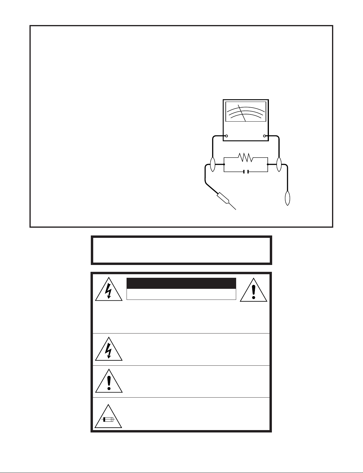
3. To be sure that no shock hazard exists, check for
current in the following manner.
● Plug the AC line cord directly into a 120 volt AC outlet
(Do not use an isolation transformer for this test).
● Using two clip leads, connect a 1.5k ohm, 10 watt
resistor paralleled by a 0.15µF capacitor in series with
all exposed metal cabinet parts and a known earth
ground, such as a water pipe or conduit.
● Use an SSVM or VOM with 1000 ohm per volt, or
higher, sensitivity or measure the AC voltage drop
across the resistor (See Diagram).
● Move the resistor connection to earth exposed metal
part having a return path to the chassis (antenna,
metal cabinet, screw heads, knobs and control shafts,
etc.) and measure the AC voltage drop across the
resistor. Reverse the AC plug on the set and repeat
AC voltage measurements for each exposed part.
Any reading of 0.45V rms (this corresponds to 0.3mA
rms AC.) or more is excessive and indicates a potential shock hazard which must be corrected before
returning the video cassette recorder to the owner.
SSVM
AC SCALE
1.5k ohms.
10W
0.15 µF
TEST PROBE
TO EXPOSED
METAL PARTS
CONNECT TO
KNOWN EARTH
GROUND
WARNING :TO REDUCE THE RISK OF FIRE OR ELEC-
TRIC SHOCK, DO NOT EXPOSE THIS APPLIANCE TO RAIN OR MOISTURE.
CA UTION
RISK OF ELECTRIC SHOCK
DO NOT OPEN
CAUTION: TO REDUCE THE RISK OF ELECTRIC SHOCK. DO
CAUTION:
3.0A 125V
NOT REMOVE COVER. NO USER-SERVICEABLE
PARTS INSIDE. REFER SERVICING TO QUALIFIED
SERVICE PERSONNEL.
This symbol warns the user of uninsulated voltage
within the unit that can cause dangerous electric shocks.
This symbol alerts the user that there are important
operating and maintenance instructions in the literature
accompanying this unit.
This symbol mark means fast operating fuse.
For continued protection against risk of fire, replace
only with same type fuse F901 (3.0A, 125V).
2

XA-905
XA-920
PRECAUTIONS IN PART REPLACEMENT
When servicing the unit with power on, be careful to the section marked white all over.
This is the primary power circuit which is live.
When checking the soldering side in the tape travel mode, make sure first that the tape has been loaded and then turn
over the PWB with due care to the primary power circuit.
Make readjustment, if needed after replacement of part, with the mechanism and its PWB in position in the main frame.
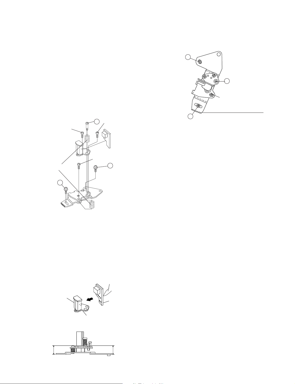
(1) Start and end sensors: Q701 and Q702
Insert the sensor’s projection deep into the upper hole of the holder. Referring to the PWB, fix the sensors tight
enough.
(2) Photocoupler: IC901
Refer to the symbol on the PWB and the anode marking of the part.
(3) Cam switches A and B: D708 and D709.
Adjust the notch of the part to the white marker of the symbol on the PWB. Do not allow any looseness.
(4) Take-up and supply sensors: D707 and D706.
Be careful not to confuse the setting direction of the parts in reference to the symbols on the PWB. Do not allow any
looseness.
3

XA-905
XA-920
1. GENERAL INFORMATION
1-1. FEATURES
Only for XA-905
• Universal Remote Control
Only for XA-920
• Hi-Fi Stereo Sound
• Built-in MTS (Multi-channel TV Sound) Decoder
• * The VCR Plus+ Programming System
• Automatic Head Cleaning System
• Built in Front AV Jacks
• Universal Remote Control with light up buttons
Common Features
• 400 Times Rewind Speed to Fast Forward and Rewind.
• EZ Set Up
• S-VHS Quasi Playback
• Double-Azimuth 4-Heads
µ Clear Picture System (in EP mode)
•19
• HQ System for Better Resolution and Color Reproduction
• Multi-Language (English/Spanish/French) OSD (On Screen
Display) with Menu Screen Guidance
• 181-channel PLL Quartz Synthesized Random Access Tuner
with Automatic Channel Setting
• Quick Start with Full Loading Mechanism
• 1-Year, 8-Event Programmable Timer
• Simple Recording Timer
• Sharp Super Picture
• Rec Tab Override
• Remote Pause IN/OUT Jacks
• BNC Video Connectors
• 3-Wire (Grounded) AC Power Cord
• 1 hour Timer Backup
• Field-Still/Variable Slow/Frame Advance
• Real-Time Counter
• Automatic Daylight Saving-Time (D.S.T.) Adjustment
• Blue Screen Noise Elimination
• Auto Tracking Control System
• Digital Program Search System (DPSS)
• Skip Search
• Instant Replay
• Exact Rec
• Tape Remaining
• One-Step Rewind
• Auto Zero Back
• Recorded Section Auto Repeat
• Full Automatic Playback
• Tamper Proof
• Up to 8 Hours of Recording and Playback (with T-160
cassette)
1-2. SPECIFICATIONS
Format: VHS NTSC Standard
Video Recording System: Rotary, Two-Head Helical Scanning
Number of Video Heads: 4
Video Signal Standard: NTSC Color System
Audio Recording System: 1 Stationary Head for Linear Audio
Tape Width: 12.7 mm (1/2 inch)
Tape Speed: (SP) 33.35 mm/sec (1.31 i.p.s.)
Maximum Recording Time: (SP) 160 min (T-160)
Channel Coverage: VHF 2-13
Antenna Input: 75 Ohm
Video Input: 0.5 to 2.0 Vp-p, 75 Ohm unbalanced
Video Output: 1.0 Vp-p, 75 Ohm unbalanced
Audio Input: –8 dBs, 47 kOhm unbalanced (0 dBs = 0.775 Vrms)
Audio Output: –8 dBs, 1 kOhm unbalanced (0 dBs = 0.775 Vrms)
Hi-Fi Audio (Only for Hi-Fi model):
Memory Backup: 1 hour
Operating Temperature: 5°C to 40°C (41°F to 104°F)
Storage Temperature: –20°C to 60°C (–4°F to 140°F)
Power Source: 120 V AC, 60 Hz
Power Consumption: 18 W
Dimensions (approx.): 360 (W) x 92.5 (H) x 262.5 (D) mm (14-3/16" x 3-41/64" x 10-21/64") (XA-905)
Weight (approx.): 2.8 kg (6.2 lbs)
Accessories included: 75 ohm coaxial cable, Operation manual, Infrared remote control, Battery (2 pcs.),
Note: Specifications are subject to change without notice.
2 Rotary Heads for Hi-Fi stereo (Only Hi-Fi model)
(LP) 16.67 mm/sec (0.66 i.p.s.) (playback only)
(EP) 11.12 mm/sec (0.44 i.p.s.)
(EP) 480 min (T-160)
UHF 14-69
CATV 1-125
Dynamic Range:
Frequency Response:
90 dB
20 Hz-20 kHz
360 (W) x 92.5 (H) x 263.5 (D) mm (14-3/16" x 3-41/64" x 10-3/8") (XA-920)
Warranty Card
4
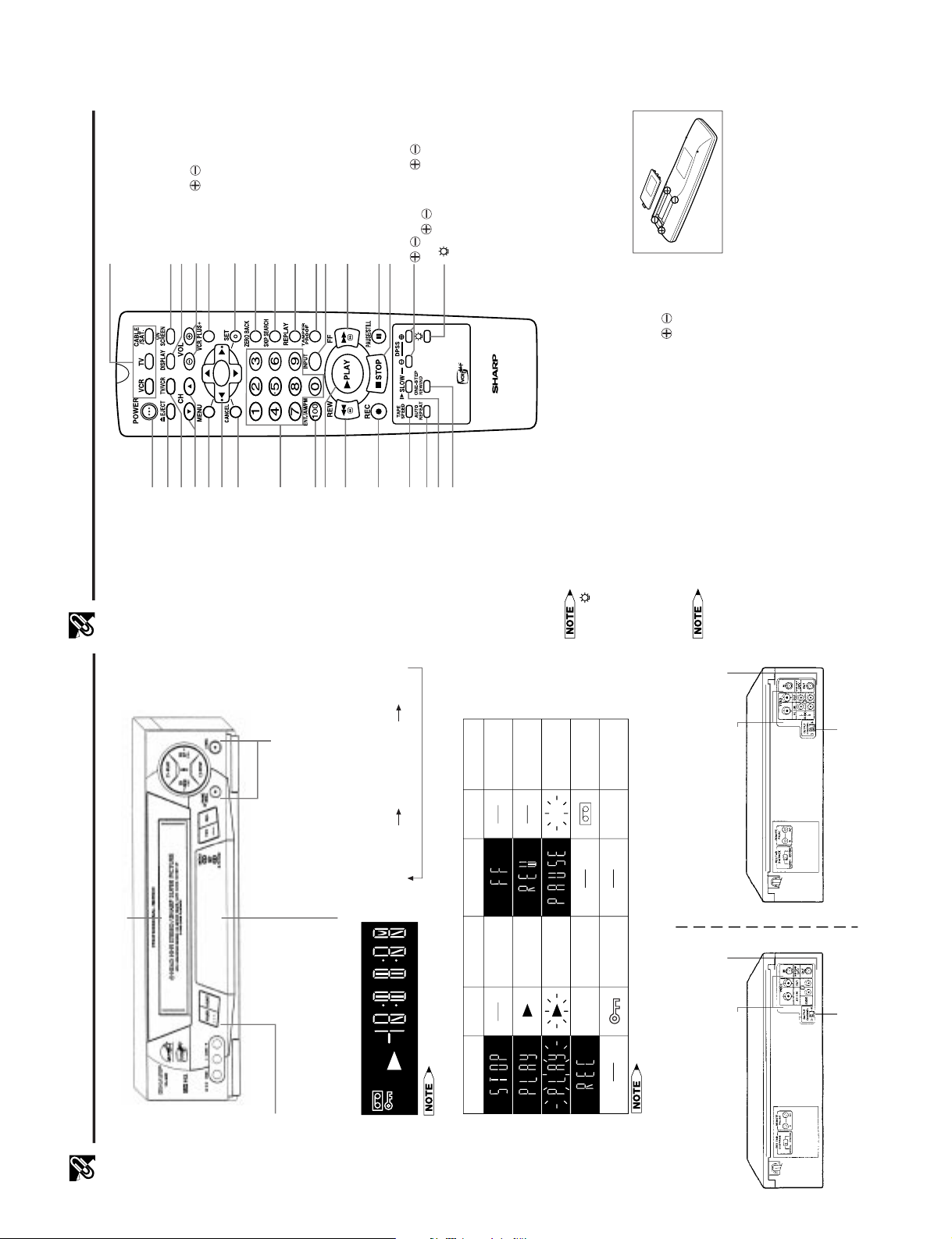
POWER button
(When pressed to turn on the VCR, some indicators
on the Multi-Function display light up, and the Multi-
Function display brightens. When the power is turned off,
the Multi-Function display dims.)
Major Components of Your VCR
[Front]
Multi-Function Display (explained throughout the operation instructions)
TIMER
REC
VCR
SPEP
Display
Symbol Function Status
Stop
Play
Fast forward
Rewind
Cassette-in
Video Search, Slow,
Still, Frame Advance
Tamper Proof
Active
Unit in
VCR mode
Record
VCR
Display
Symbol Function Status
REC
REC
Rec Pause
[Rear]
! Channel setting @ Tape counter # Clock
Cassette compartment (see Playback/Recording)
Basic function controls
(see Playback/Recording)
When the power is on, each time DISPLAY is pressed,
the Multi-Function display changes as follows:
•Tape counter is displayed during playback, fast forward or rewind operation.
•When the power is turned off, the clock is displayed and the Multi-Function display becomes darker.
•The display will return to the original mode (counter or clock display) 3 seconds after the
VCR enters the operation mode.
Connection terminals (see Connecting the VCR and
Cable TV Connections)
Connection terminals (see Tape Dubbing)
3 ↔ 4 OUTPUT CHANNEL selector
(see Setting the 3 ↔ 4 Output Channel Selector)
(XA-920)
(XA-920)
Connection terminals (see Connecting the VCR and
Cable TV Connections)
Connection terminals (see Tape Dubbing)
3 ↔ 4 OUTPUT CHANNEL selector
(see Setting the 3 ↔ 4 Output Channel Selector)
(XA-905)
1-3. LOCATION OF MAJOR COMPONENTS AND CONTROL
VIDEO CASSETTE RECORDER
Remote Control
MENU button
Remote Control Mode Select
buttons (VCR, TV, CABLE/SAT.)
• USED TO SELECT THE
COMPONENT (VCR, TV, CABLE
BOX/SAT.) TO BE OPERATED.
DISPLAY button
ON SCREEN button
SET button
VCR Plus+ button
ZERO BACK button
SKIP SEARCH button
REPLAY button
PAUSE/STILL button
TAMPER PROOF button
*STOP button
button (XA-920)
*FF button
POWER button
EJECT button
TV/VCR button
*REW button
REC button
TAPE SPEED button
*Numbered buttons
*PLAY button
*100, ENT. /AM/PM button
AUTO REPEAT button
CANCEL button
INPUT button
SLOW button
Inserting the Batteries
Make sure that the batteries have been properly installed first. Fit two batteries
• If the button is pressed while the light up buttons are illuminated,
they will remain illuminated for an additional seconds.
type "AA". If the remote control stops working, fit new batteries.
Ensure the batteries are fitted correctly, matching the polarities ( / ) indicated
in the remote control.
• After changing the batteries in the remote control, the code settings for the TV,
cable box and Digital Satellite Receiver must be re-entered.
• Do not subject the remote control to shock, water or excessive humidity.
• The remote control may not function if the VCR sensor is in direct sunlight or any other strong light.
• The operating life of the batteries will shorten if the Light Up function is frequently used.
• The operating life of the batteries will shorten if the Remote Pager function is frequently used.
• Incorrect use of batteries may cause them to leak or burst. Read the battery warnings and use the batteries properly.
• Do not mix old and new batteries, or mix brands in use.
• Remove the batteries if the remote control will not be operated for an extended period of time.
• If the remote control does not function properly when new batteries are installed, remove the batteries and keep pressing
any button for 10 seconds before re-installing them.
RENTAL REWIND button
CH (CHANNEL) '/" buttons
"/'/\/| button
VOL (VOLUME) / buttons
/ buttons (SLOW / ,
DPSS / )
• Press the button to illuminate
the light up buttons (indicated)
with the * mark) for 10
seconds.
XA-920
XA-905
XA-920
5
XA-905
XA-920
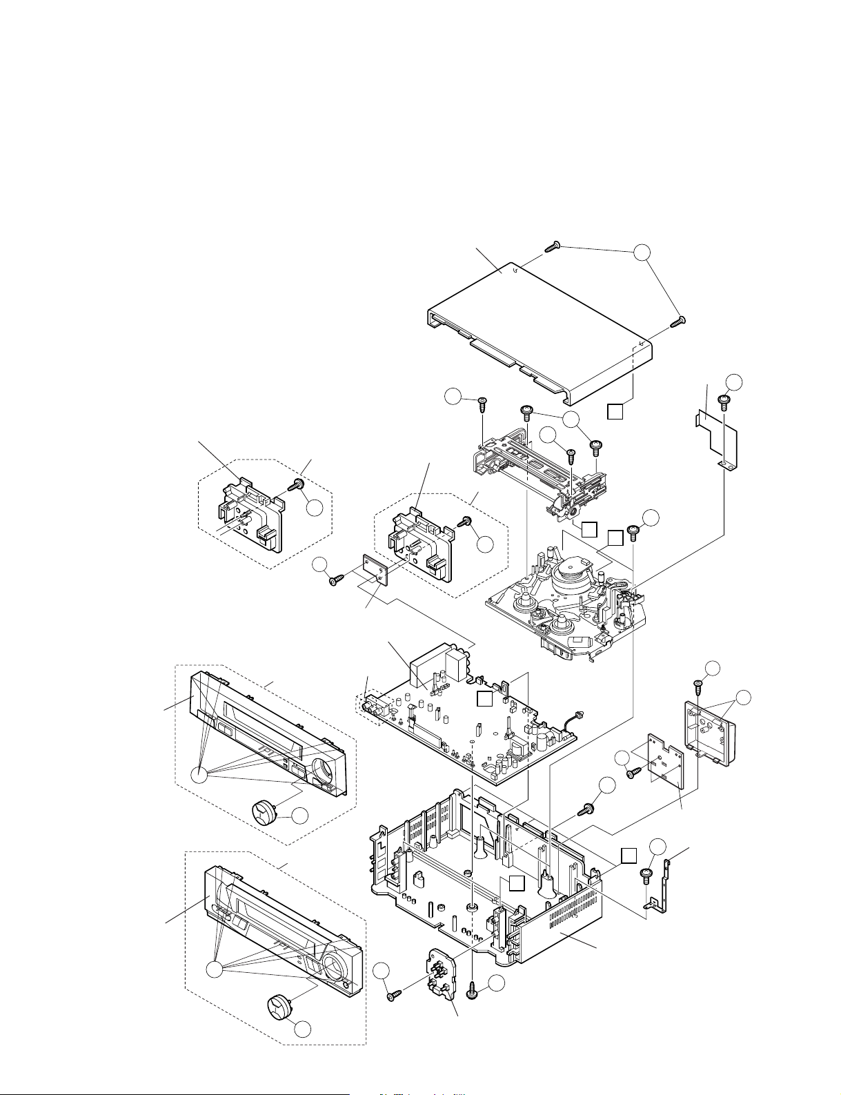
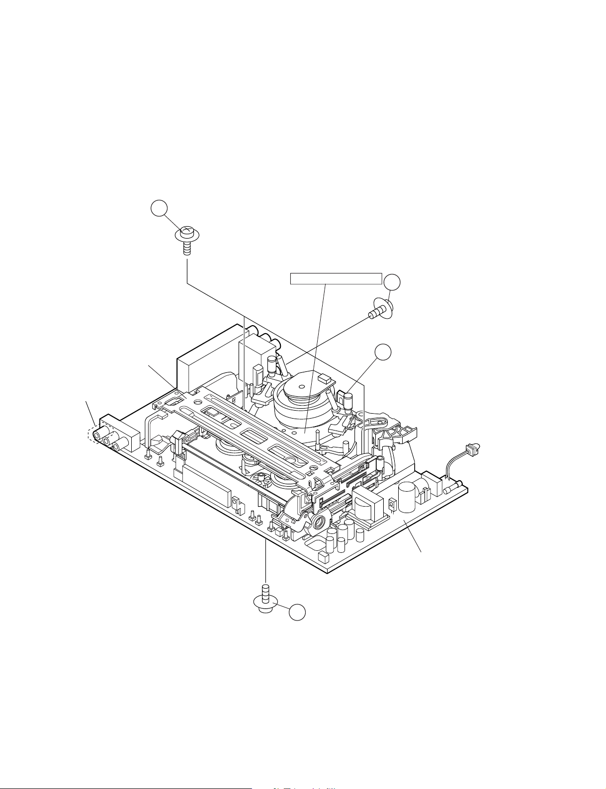
2. DISASSEMBLY AND REASSEMBLY
2-1. DISASSEMBLY OF MAJOR BLOCKS
TOP CABINET : Remove 2 screws 1.
FRONT PANEL : Remove button 2.
Remove 2 screws 3 and 7 clips 4.
OPERATION : Remove 1 screw 5.
PWB
SHIELD ANGLE : Remove 1 screw 6 with shield angle.
MECHANISM/ : Remove 1 screw 7, 1 screw 8, 2
MAIN PWB screws 9, 2 screws 0. Remove 1
screw q with antenna terminal cover.
Remove 1 screw w with top cabinet
fix angle.
ANTENNA
TERMINAL
COVER
XA-920
11
16
PAUSE JACK : Remove 3 screws e, 1 screw r, 2
PWB clips t with Pause Jack PWB and
Pause Jack cover.
Disconnect earth lead and wire lead.
VIDEO JACK : Remove 2 screws y and disconnect
PWB wire lead.
TOP CABINET
1
SHIELD
ANGLE
3
C
B
9
A
ANTENNA
TERMINAL
COVER
10
3
XA-905
11
6
FRONT P ANEL
FRONT P ANEL
VIDEO JACK PWB
MECHANISM/
MAIN PWB ASSEMBLY
Except
( )
XA-905
4
2
XA-920
4
XA-905
A
13
7
PAUSE JACK PWB
12
C
B
5
8
MAIN FRAME
14
15
TOP CABINET
FIX ANGLE
2
OPERATION PWB
6
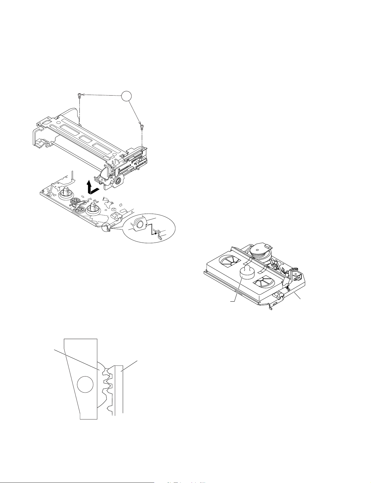
2-2. DISASSEMBLING THE MECHANISM/MAIN PWB ASSEMBLY
XA-905
XA-920
1. When removing the mechanism from the main PWB,
remove the antenna cover 1 screw 1, and remove the
antenna cover.
Remove the PWB bottom plate 1 screw 2.
Remove the FFC cable (AA, AD, AH) 3 which connecting the PWB and the mechanism.
Take out vertically the mechanism so that it does not
damage the adjacent parts.
4
CASSETTE
HOUSING
2. Removing the mechanism and cassette housing.
Remove 2 screws 4 fixing the cassette housing to the
mechanism, and remove the cassette housing.
MECHANISM CHASSIS
1
3
Except XA-905
MAIN PWB
2
7

XA-905
XA-920
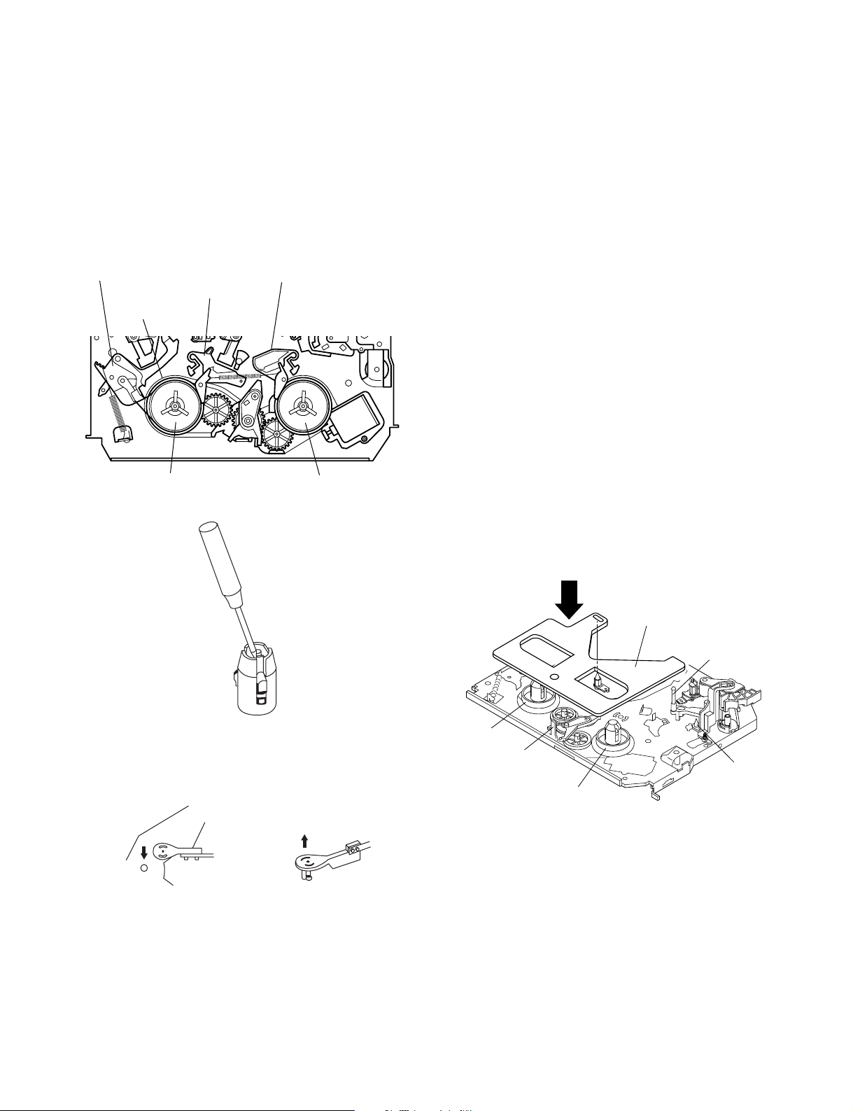
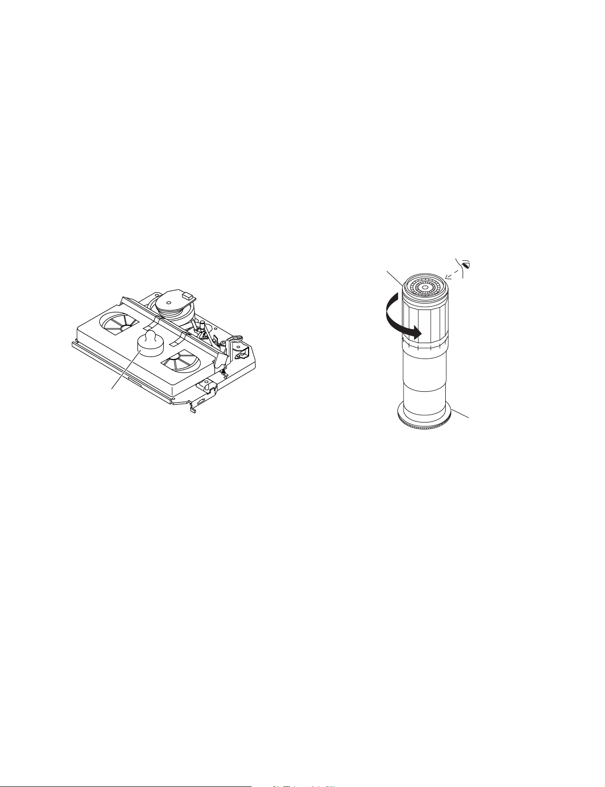
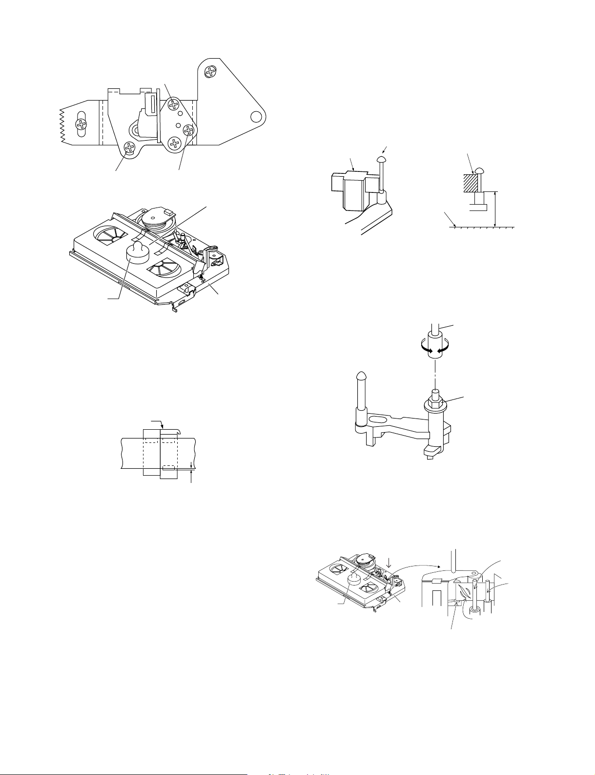
2-3. CARES WHEN REASSEMBLING
INSTALLING THE CASSETTE HOUSING
When the cassette housing is installed on the mechanism,
the initial setting is essential condition.
There are two initial setting methods, namely electrical and
mechanical.
1. Electrical initial setting
So as to perform initial setting of mechanism execute the
Step 1 of Installation of cassette housing. After ascertaining
the return to the initial setting position (*1) install the
Pulley feed gear
Screwdriver
Tilt mark (*1)
cassette housing. (Conditions: When mechanism and PWB
have been installed)
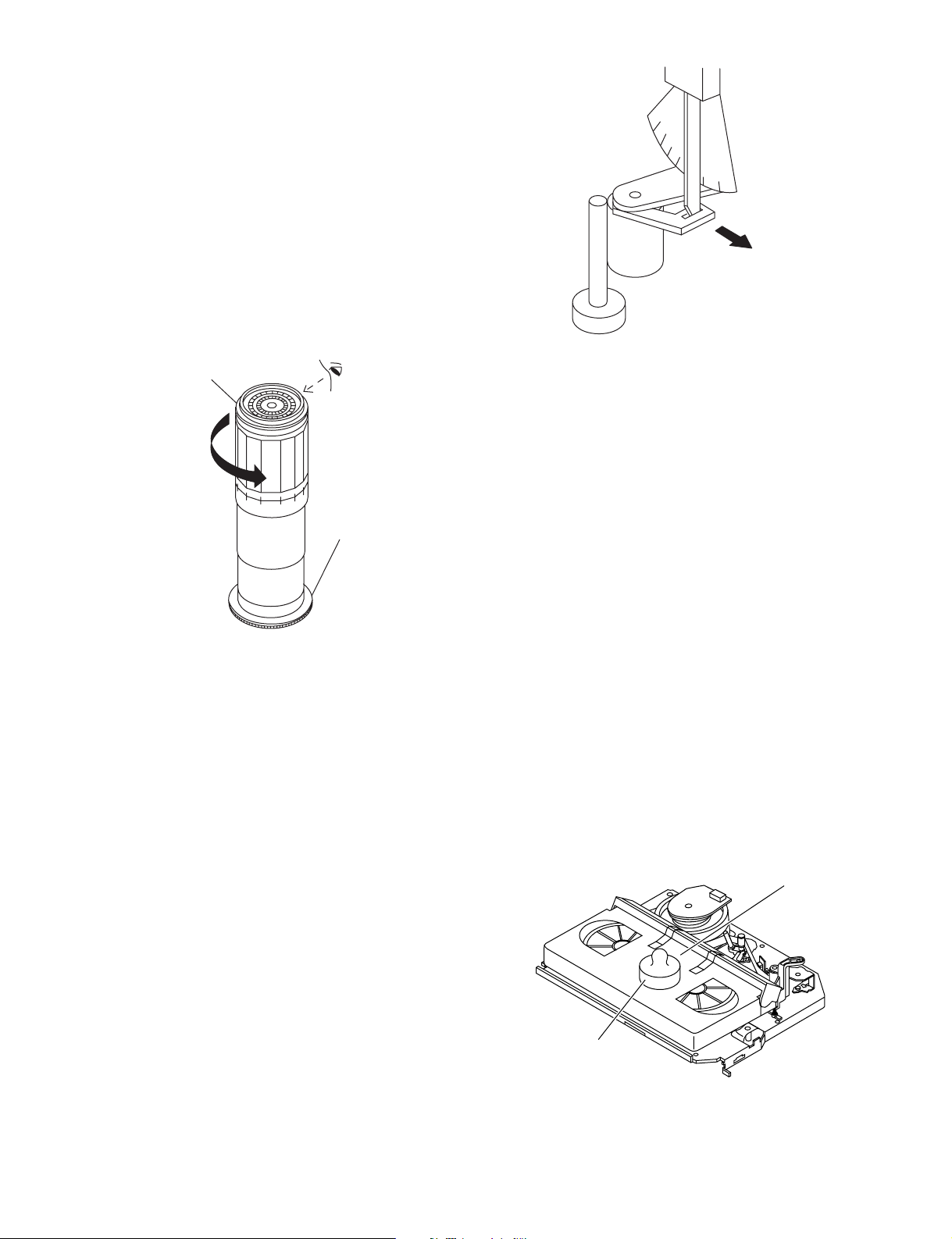
2. Mechanical initial setting
Feed the pulley feed gear of loading motor with screw
driver. After ascertaining the return to the initial set position
(*1) install the cassette housing in the specified position.
(This method is applied only for the mechanism.)
Casecon
drive gear
Drive angle of
cassette housing
INSTALLING THE MECHANISM ON PWB
Lower vertically the mechanism, paying attention to the
mechanism edge, and install the mechanism with due care
so that the parts are not damaged. So as to fix the mechanism to the main PWB install two housings. (Fit the antenna
cover to one of them. For other, fix the vicinity of loading
motor and solder joint side of main PWB.) Connect again
the FFC cable (AA-MH, AD-ME, AH-MH) between the
mechanism and the main PWB.
END SENSOR
REC TIP SW
Except XA-905
PARTS WHICH NEED PARTICULAR CARE
When installing the mechanism chassis on the PWB unit,
take care so as to prevent deformation due to contact of
mechanism chassis with REC TIP SW.
AE CONNECTOR
AC CONNECTOR
START SENSOR
AL CONNECTOR
8
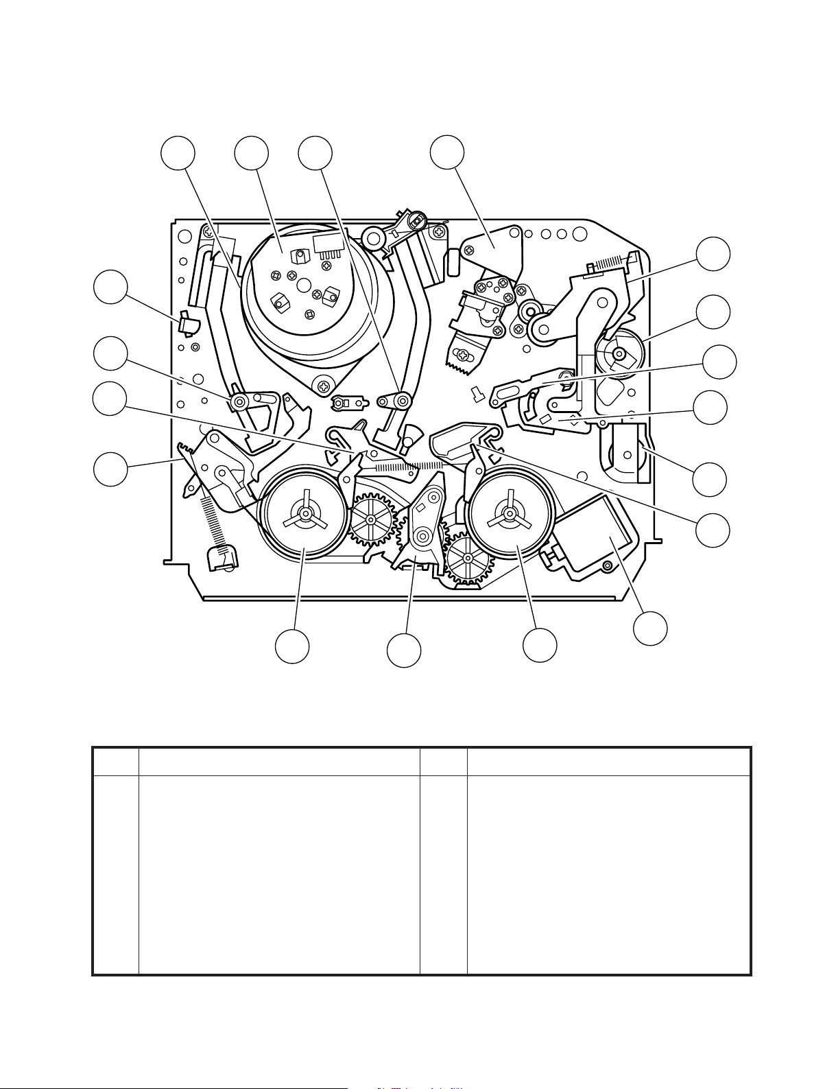
3. FUNCTION OF MAJOR MECHANICAL PARTS (TOP VIEW)
XA-905
XA-920
15
17
18
10
14
1
9
2
7
3
11
5
12
8
6
No. Function
1 Full erase head
2 Supply pole base ass’y
3 Tension arm
4 Idler wheel ass’y
5 Pinch drive lever ass’y
6 Supply reel disk
7 Supply main brake
4
No. Function
8 Take-up main brake
9 Pinch drive cam
10 A/C head ass’y
11 Reverse guide lever ass'y
12 Casecon drive gear
13 Take-up reel disk
14 Pinch roller lever ass’y
13
16
9
XA-905
XA-920
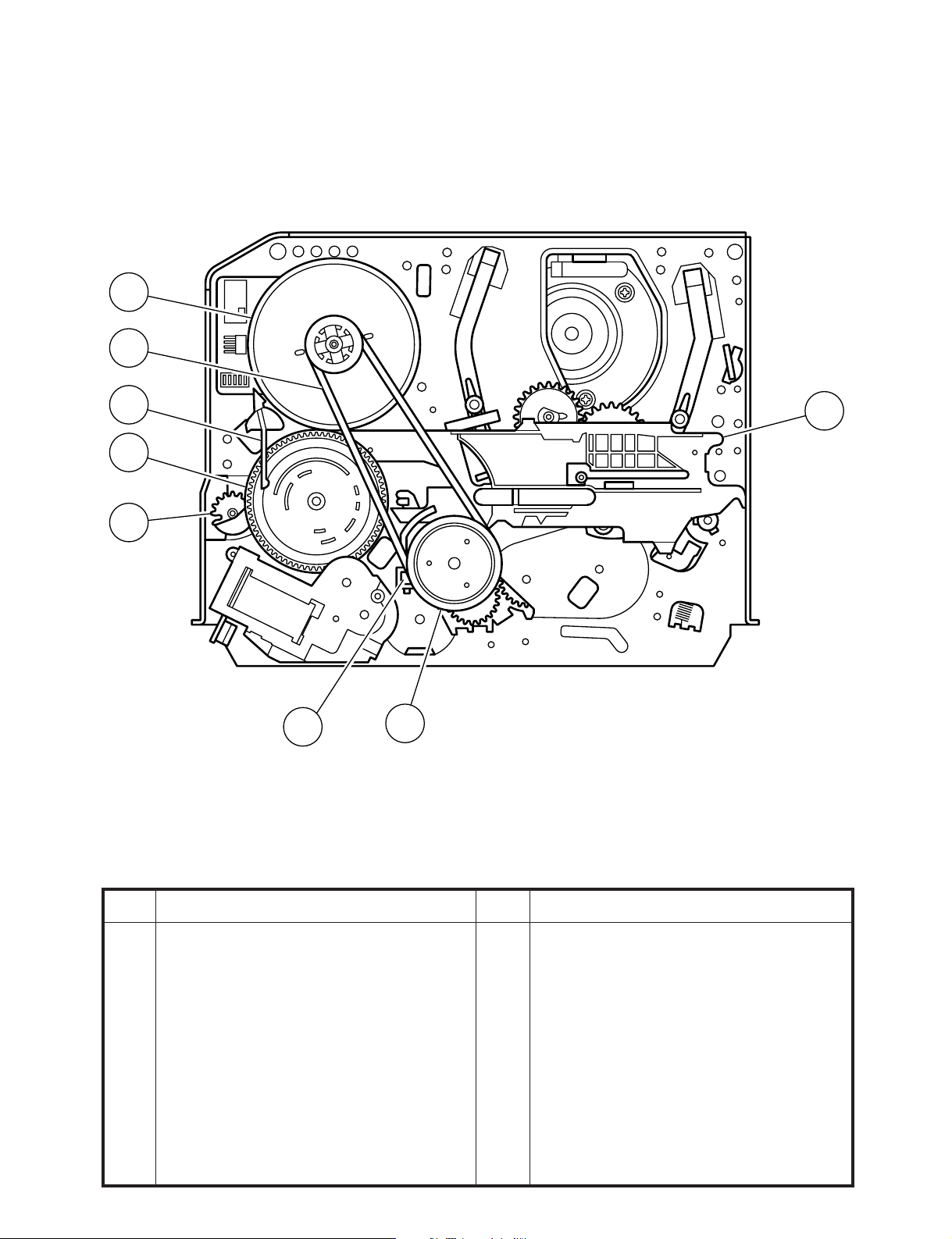
FUNCTION OF MAJOR MECHANICAL PARTS (BOTTOM VIEW)
21
22
19
20
12
23
25
24
No. Function
15 Drum ass’y
16 Loading motor
17 Drum drive motor
18 Take-up pole base ass’y
19 Slow brake lever
20 Master cam
21 Capstan D.D. motor
No. Function
22 Reel belt
23 Clutch lever
24 Limiter pulley ass'y
25 Shifter
10
XA-905
XA-920
4. ADJUSTMENT, REPLACEMENT AND ASSEMBLY OF MECHANICAL UNITS
The explanation given below relates to the on-site general service (field service) but it does not relates to the adjustment
and replacement which need high-grade equipment, jigs and skill. For example, the drum assembling, replacement and
adjustment service must be performed by the person who have finished the technical courses.
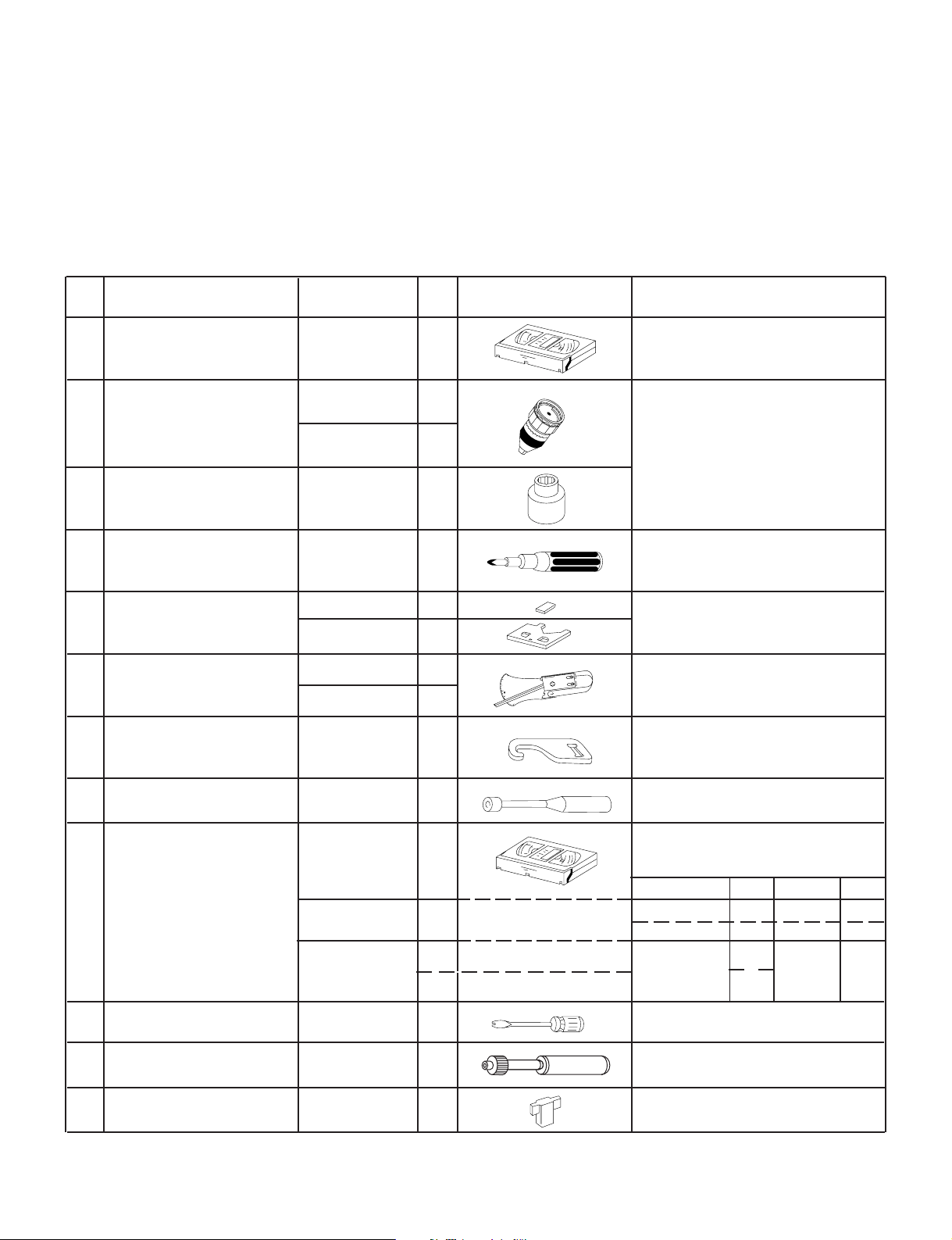
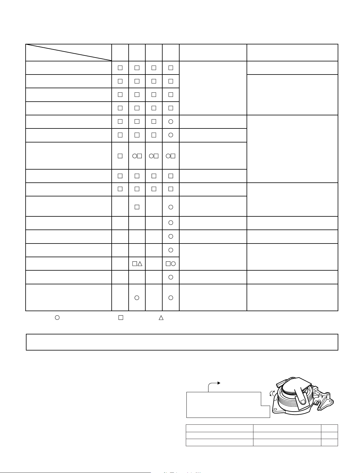
4-1. MECHANISM CONFIRMATION ADJUSTMENT JIG
So as to perform completely the mechanism adjustment prepare the following special jigs. So as to maintain the initial
performance of the machine the maintenance and check are necessary. Utmost care must be taken so that the tape is
not damaged. If adjustment needs any jig, be sure to use the required jig.
No. Jig ltem Part No. Code Configuration Remarks
This cassette torque meter is used for check-
1. Torque Cassette Meter JiGVHT-063 CZ
JiGTG0090 CM
2.
Torque Gauge
JiGTG1200 CN
3. Torque Gauge Head JiGTH0006 AW
ing and adjusting the torque of take-up for
measuring tape back tension.
These Jigs are used for checking
and adjusting the torque of take-up
and supply reel disks.
4. Torque Driver JiGTD1200 CB
Master Plane Jig and
Reel Disk Height
5.
Adjusting Jig
JiGRH0002 BR
JiGMP0001 BY
JiGSG2000 BS
Tension Gauge
6.
JiGSG0300 BF
Pinch pressing force
7. JiGADP003 BK
measuring jig
Reverse guide height
8.
adjustment box driver
9.
Alignment Tape
JiGDRiVER11055
AR
VROATSV CD
VROEFZCS
BG
or
VROEFZHS
Guide roller height
10. JiGDRiVERH-4 AP
adjustment driver
BH
When fixing any part to the threaded
hole using resin with screw, use the
jig. (Specified torque 5 kg)
These Jigs are used for checking
and adjusting the reel disk height.
There are two gauges used for the
tension measurements, 300 g and
2.0 kg.
This Jig is used with the tension
gauge. Rotary transformer clearance
adjusting jig.
This Jig is used for height adjustment of the
reverse guide (for reverse guide height adjustment).
These tapes are especially used for
electrical fine adjustment.
Video Audio HiFi Audio Track
525 Monoscope 7k — 58µm
NTSC Color Bar 1k — 58µm
Black Level
(only SYNC) signal
This screwdriver is used for adjusting the
guide roller height.
1k
—19µm
2.3k
X value adjustment
11. JiGDRiVER-6 BM
gear driver
Reverse Guide Height
12.
Adjusting Jig
JiGRVGH-F18
BU
For X value adjustment
This Jig is used for height
adjustment of the reverse guide.
11
XA-905
XA-920
4-2. MAINTENANCE CHECK ITEMS AND EXECUTION TIME
Perform the maintenance with the regular intervals as follows so as to maintain the quality of machine.
Maintained
Parts
Guide roller ass’y
Sup guide shaft
Reverse guide
Slant pole on pole base
Full erase head
A/C head
Upper and lower drum ass’y
Capstan D.D. motor
Pinch roller
Reel belt
500
hrs.
1000
hrs.
1500
hrs.
2000
hrs.
Possible symptom
encountered
Lateral noises Head
occasionally blocked
Colour and beating
Small sound or sound
distortion
Poor S/N ratio, no colour
Poor flatness of the
envelope with alignment
tape
No tape running,
uneven colour
No tape running, tape
slack
No tape running, tape
slack, no fast forward/
rewind motion
Remarks
Abnormal rotation or significant
vibration requires replacement.
Clean tape contact part with the
specified cleaning liquid.
Clean tape contact area with the
specified cleaning liquid.
Clean rubber and rubber contact
area with the specified cleaning
liquid.
Tension band ass’y
Loading motor
Idler ass’y
Limiter pulley
Supply/take-up main brake levers
Screen swaying
Cassette not loaded or
unloaded
No tape running, tape
slack
Tape slack
Replace the roller of the cleaner
AHC (Automatic Head Cleaner)
(XA-920)
when it wears down.
Just change the AHC roller
assembly for new one.
NOTE : Part replacement. : Cleaning : Apply grease
<Specified> Cleaning liquid Industrial ethyl alcohol
* This mechanism does not need electric adjustment with variable resistor. Check parts. If any deviation is found,
clean or replace parts.
Video head cleaning procedure
1. Apply one drop of cleaning liquid to the cleaning paper with the baby oiler.
2. Gently press the cleaning paper against the video head to fix your finger, and move the upper drum so that each head
is passed to and fro 5 times (do not move the cleaning paper).
3. Wipe with the dry cleaning paper.
Notes :
• Use the commercially available ethanol of Class 1 as
cleaning liquid.
• Since the video head may be damaged, do not move up
and down the cleaning paper.
Gently press the cleaning paper to
fix with your finger, and rotate the
upper drum to clean.
Move to and fro 5 times for each head.
(Do not move the cleaning paper.)
Rotate the upper drum
with one hand.
• Whenever the video head is cleaned, replace the cleaning paper.
• Do not apply this procedure for the parts other than the
video head.
Parts Code Description Code
ZPAPRA56-001E Cleaning Paper AW
ZOiLR-02-24TE Babe Oiler (Spoit) AH
12
XA-905
XA-920
4-3. REMOVING AND INSTALLING THE CAS-
SETTE HOUSING
• Removal
1. In the cassette removing mode, remove the cassette.
2. Unplug the power cord.
3. Remove in the following numerical order.
a) Remove two screws 1.
b) Slide and pull up the cassette housing control.
1
Notes:
1. When fitting the S/E sensor holder to the cassette
controller frame L/R, take care.
2. Misengagement of teeth of casecon drive gear and drive
angle gear causes malfunction. (The cassette cannot be
set, load and ejection are repeated).
3. In the case when you use the magnet screw driver, never
approach the magnet driver to the A/C head, FE head,
and drum.
4. When installing or removing, take care so that the
cassette housing control and tool do not contact the
guide pin or drum.
5. After installing the cassette housing control once perform cassette loading operation.
4-4 . TO RUN A TAPE WITHOUT THE CAS-
SETTE HOUSING CONTROL ASSEMBLY
1. Remove the full-surface panel.
2. Short-circuit TP803 and TP802.
3. Plug in the power cord.
4. Turn off the power switch.
(The pole bases move into U.L.position.)
5. Open the lid of a cassette tape by hand.
6. Hold the lid with two pieces of vinyl tape.
7. Set the cassette tape in the mechanism chassis.
8. Stabilize the cassette tape with a weight (500g) to
prevent floating.
9. Turn on the power switch.
10. Perform running test.
Figure 4-1.
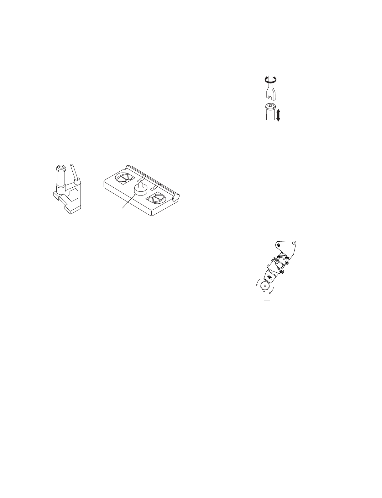
• Reassembly
1. Before installing the cassette housing control, shortcircuit TP803 and TP802 provided at operation PWB,
press the eject button. The casecon drive gear turns and
stops when the positioning mark appears. Engage two
teeth of casecon drive gear with the three teeth of
casecon drive angle gear, and set on the mechanism
chassis as shown below.
Casecon
drive gear
Casecon drive
angle gear
500g
Weight to prevent
float (500g)
Mechanism chassis
Figure 4-3.
Note:
The weight should not be more than 500g.
To take out the cassette tape.
1. Turn off the power switch.
2. Take out the cassette tape.
Figure 4-2.
2. Install in the reverse order of removal.
13
XA-905
XA-920
4-5. REEL DISK REPLACEMENT AND
HEIGHT CHECK
• Removal
1. Remove the cassette housing control assembly.
2. Pull the tension band out of the tension arm ass'y.
3. Remove the Supply/Take-up main brake ass'y.
4. Open the hook at the top of the reel disk, and remove the
reel disk.
Note:
Take care so that the tension band ass'y and main brake
ass'y (especially soft brake) are not deformed.
Tension arm ass'y
Supply main brake ass'y
Tension band ass'y
Supply reel disk
Take-up main brake ass'y
Take-up reel disk
4. Assemble the Supply main brake ass'y.
Notes:
1. When installing the reel disk, take due care so that the
tension band ass'y is not deformed and grease does no
adhere.
2. Do not damage the Supply main brake ass'y. Be careful
so that grease does not adhere to the brake surface.
• Reassembly (Take-up reel disk)
1. Clean the reel disk shaft and apply grease (SC-141) to
it.
2. Align the phase of the reel disk to that of the reel relay
gear and to install a new take-up reel disk onto the shaft.
3. Check the reel disk height and reassemble the take-up
main brake ass'y.
Note:
1. Take care so that the Take-up main brake ass'y is not
damaged. Take care so that grease does not adhere the
brake surface.
2. After reassembly, check the video search rewind back
tension (see 4-10), and check the brake torque (see 4-
14).
• Height checking and adjustment
Note:
1. Set the master plane with due care so that it does not
contact the drum.
2. When putting the master plane, shift the reverse guide
a little in the loading direction. Care must be taken since
excessive shift results in damage.
Figure 4-4.
Note:
When the tension band ass'y is pressed in the direction of
the arrow for removal, the catch is hard to be deformed.
Figure 4-5.
• Reassembly (Supply reel disk)
1. Clean the reel disk shaft and apply grease (SC-141) to
it.
2. Match the phases of reel disk and reel relay gear, and set
the new reel disk.
3. After checking the reel disk height, wind the tension
band ass'y around the reel disk, and insert into the hole
of tension arm ass'y.
Master plane
Reverse
guide
Supply reel disk
Cassette lock
release shaft
Take-up reel disk
Position
pin
Figure 4-6.
Note:
• Check that the reel disk is lower than part A but higher
than part B. If the height is not correct, readjust the reel
disk height by changing the poly-slider washer under the
reel disk.
14
XA-905
XA-920
Note:
Whenever replacing the reel disk, perform the height checking and adjustment.
Master plane
10 ± 0.2mm
Reel disk
Reel disk
Reel disk height
adjusting jig
Mechanism chassis
A
B
Figure 4-7.
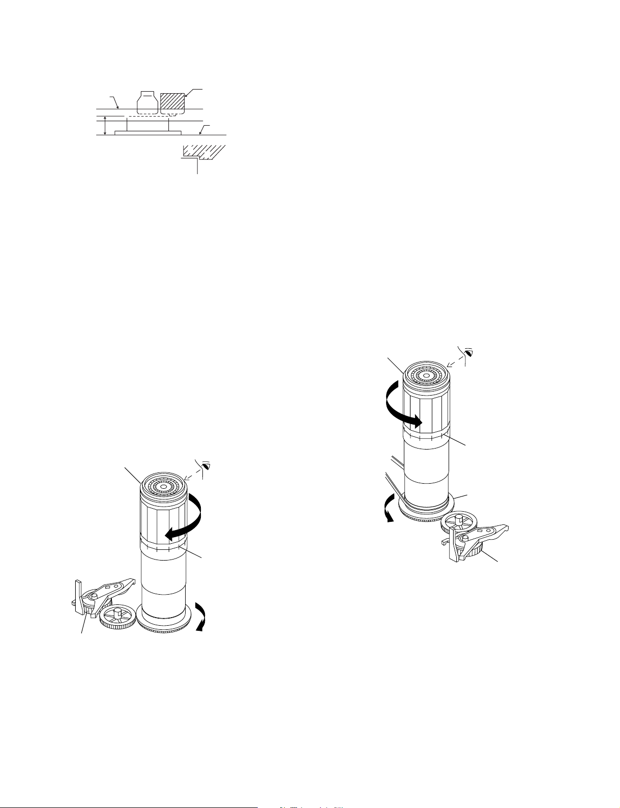
4-6. CHECKING AND ADJUSTMENT OF
TAKE-UP TORQUE IN FAST FORWARD
MODE
• Remove the cassette housing control assembly.
• After short-circuiting TP803 and TP802 provided at
operation PWB, plug in the power cord.
• Setting
1. Set a torque gauge to zero on the scale. Place it on the
take-up reel disk.
2. Press the FF button.
3. To calculate the remaining capacity of the play back
mode, slowly rotate the supply reel disk, and then shift
it into the forward mode.
• Checking
1. Turn the torque gauge slowly (one rotation every 2 to 3
seconds) by hand in the CW direction.
Torque gauge
Notes:
1. Hold the torque gauge by hand so that it is not moved.
2. Do not keep the reel disk in lock state. Do not allow longtime measurement.
4-7. CHECKING AND ADJUSTMENT OF
TAKE-UP TORQUE IN REWIND MODE
• Remove the cassette housing control assembly.
• After short-circuiting TP803 and TP802 provided at
operation PWB, plug in the power cord.
• Setting
1. Set a torque gauge to zero on the scale. Place it on the
supply reel disk.
2. Press the rewind button.
3. To calculate the remaining capacity, slowly rotate the
take-up reel disk, and then shift it into the rewind mode.
• Checking
1. Turn the torque gauge slowly (one rotation every 2 to 3
seconds) by hand in the CCW direction.
2. Make sure that the indication of torque gauge is not less
than 30mN·m (306gf·cm).
Torque gauge
30mN·m (306gf·cm)
or more
CCW
The gauge is held at
its maximum value.
(Red mark)
30mN·m (306gf·cm)
or more
Idler ass'y
CW
The gauge is held at
its maximum value.
(Red mark)
Figure 4-8.
2. Make sure that the indication of torque gauge is not less
than 30mN·m (306gf·cm).
• Adjustment
1. If the FF winding-up torque is less than the specified
value, clean the capstan D.D. motor pulley, drive belt,
and limiter pulley with cleaning liquid, and check again.
2. If the torque is less than the set value, replace the reel
belt.
Supply reel disk
Idler ass'y
Figure 4-9.
• Adjustment
1. If the rewind winding-up torque is less than the specified
value, clean the capstan D.D. motor pulley, drive belt,
and limiter pulley with cleaning liquid, rewind again, and
check the winding-up torque.
2. If the winding-up torque is still out of range, replace the
drive belt.
15
XA-905
XA-920
Notes:
1. Hold the torque gauge by hand so that it is not moved.
2. Do not keep the reel disk in lock state. Do not allow longtime measurement.
4-8. CHECKING AND ADJUSTMENT OF TAKE-
UP TORQUE IN RECORD/PLAYBACK
MODE
• Remove the cassette housing control assembly.
• After short-circuiting TP803 and TP802 provided at
operation PWB, plug in the power cord.
• Turn off the power switch.
• Open the cassette torque meter lid, and fix it with
tape.
• Load the cassette torque meter into the unit.
• Put the weight (500g) on the cassette torque meter.
• Turn on the power switch.
Set value EP6.9 ± 2.5mN⋅m (70 ± 25gf⋅cm)
4-9. CHECKING AND ADJUSTMENT OF
TAKE-UP TORQUE IN VIDEO SEARCH
REWIND MODE
• Remove the cassette housing control assembly.
• After short-circuiting TP803 and TP802 provided at
operation PWB, plug in the power cord.
• Setting
Press the playback button and rewind button to set the
video search rewinding mode.
• Checking
Place the torque gauge on the supply reel disk, and turn it
counterclockwise very slowly (one rotation every 1 to 2
seconds) and check that the torque is within the set value
14.0 ± 3.9mN⋅m. (144 ± 40gf⋅cm)
Torque gauge
CCW
500g
Cassette torque meter
Figure 4-10.
• Press the picture record button, and set EP picture
record mode (x3).
• Checking
1. Make sure that value is within the setting 6.9 ± 2.5mN·m
(70 ± 25gf·cm).
2. The winding-up torque fluctuates due to variation of
rotation torque of limiter pulley ass'y. Read the center
value of fluctuation as setting.
3. Set the EP record mode (x3) and make sure that the
winding-up torque is within setting.
• Adjustment
If the playback winding-up torque is not within the setting,
replace the limiter pulley assembly.
Note:
When the torque cassette is set, put a weight (500g) to
prevent rise.
When the cassette torque meter is taken out.
Turn off the power switch.
Supply reel disk
Figure 4-11.
Note:
Surely put the torque gauge on the reel disk to measure. If
the torque gauge is raised, accurate measurement is
impossible.
• Adjustment
If the rewinding playback winding-up torque is not within the
setting, replace the limiter pulley assembly.
Note:
The winding-up torque fluctuates due to variation of rotation torque of supply reel disk. Read the center value of
fluctuation as setting.
16
4-10. CHECKING THE VIDEO SEARCH
REWIND BACK TENSION
• Remove the cassette housing control assembly.
XA-905
XA-920
• After short-circuiting TP803 and TP802 provided at
operation PWB, plug in the power cord.
• Checking
1. After pressing the play button, press the rewind button,
and set the video search rewind mode.
2. Place the torque gauge on the take-up reel disk, and turn
it counterclockwise very slowly (one rotation every 2 to
3 seconds) and check that the torque is within the set
value 3.4 ± 1.5mN⋅m (35 ± 15gf⋅cm).
Torque gauge
CCW
Take-up reel disk
Pinch roller
Capstan shaft
Tension gauge adapter
Tension gauge
900 - 1,200gf
Figure 4-13.
1. Detach the pinch roller from the capstan shaft.
Do not separate excessively. Or the pinch lever and
pinch double action lever may disengage.
2. Engage the tension gauge adapter with the pinch roller
shaft, and pull in the arrow direction.
3. Gradually return the pinch roller, and measure the
pulling force when the pinch roller contacts the capstan
shaft.
4. Make sure that the measured value is within setting 9.0
N to 11.8 N (900 to 1,200gf).
Figure 4-12.
Notes:
Set the torque gauge securely on the take-up reel disk.
If it is not secure, the measurement will be incorrect.
4-11. CHECKING THE PINCH ROLLER
PRESSURE
• Remove the cassette housing control assembly.
• After short-circuiting TP803 and TP802 provided at
operation PWB, plug in the power cord.
• Checking
Press the play button to set the playback mode.
4-12. CHECKING AND ADJUSTMENT OF
TENSION POLE POSITION
• Remove the cassette housing control assembly.
• After short-circuiting TP803 and TP802 provided at
operation PWB, plug in the power cord.
• Setting
1. Turn off the power switch.
2. Open the cassette tape (T-120), and fix with tape.
3. Set the cassette tape in loading state.
4. Put the weight (500g) on the cassette tape.
5. Turn on the power switch.
6. Make the adjustment with the beginning of a T-120 tape.
(T-120)
500g
Weight to prevent
float (500g)
Figure 4-14.
• Checking
1. Set a cassette tape, push the REC button to place the
unit in the SP record mode. Now check the tension pole
position.
17
XA-905
XA-920
2. Visually check to see if the right edge of the tension pole
is within the 2.3 ± 0.25 from the right edge of the Sup
guide shaft.
Sup guide shaft
Tension pole
2.3 ± 0.25
Make the adjustment with the beginning of a T-120 tape.
Figure 4-15.
At left side from the center line
Tension pole adjuster adjusting range
Tension pole adjuster
90°
90°
Figure 4-18.
Adjust so that the delta mark of tension pole adjuster is
within 90° range (left, right).
4-13. CHECKING AND ADJUSTMENT OF
RECORD/PLAYBACK BACK TENSION
• Remove the cassette housing control assembly.
2.3 ± 0.25
Figure 4-16.
Insert the slotted screwdriver in the tension pole adjuster,
and rotate counterclockwise.
At right side from the center line
2.3 ± 0.25
Figure 4-17.
Insert the slotted screwdriver in the tension pole adjuster,
and rotate clockwise.
• After short-circuiting TP803 and TP802 provided at
operation PWB, plug in the power cord.
• Setting
1. Turn off the power switch.
2. Open the torque cassette meter and fix with tape.
3. Set the cassette tape in loading state.
4. Put the weight (500g) on the cassette torque meter.
5. Turn on the power switch.
500g
Weight to prevent
float (500g)
Cassette torque
meter
Figure 4-19.
• Checking
1. Push the REC button to place the unit in the SP record
mode.
2. At this time ascertain that the back tension is within the
setting (36.5 to 52g·cm) by seeing the indication of
torque cassette meter.
18
XA-905
XA-920
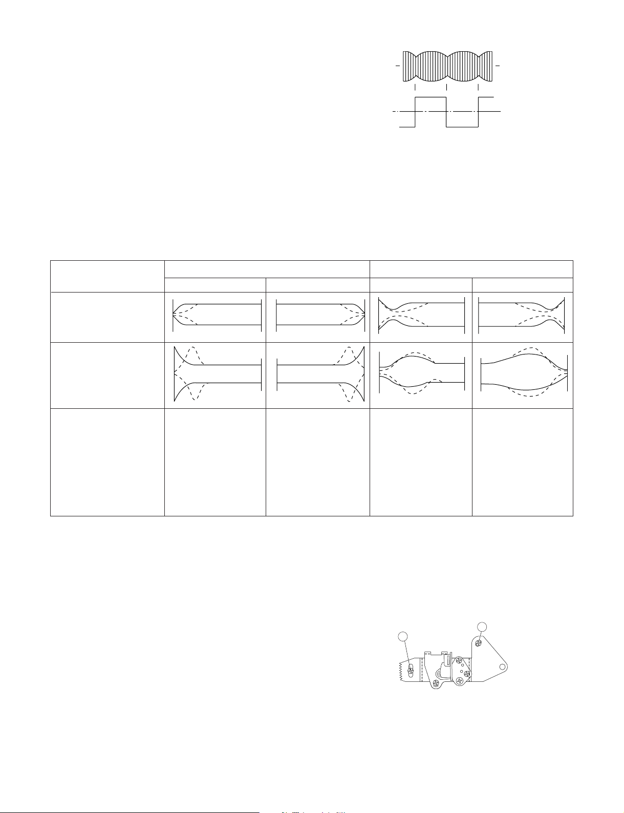
• Adjustment
1. If the indication of torque cassette meter is lower than
the setting, shift the tension spring engagement to the
part A.
2. If the indication of torque cassette meter is higher than
the setting, shift the tension spring engagement to the
part B.
A
B
Tension arm
Tension spring
Figure 4-20.
4-14. CHECKING THE BRAKE TORQUE
• Checking the brake torque at the supply side
Torque gauge
CCW
CW
• Checking the brake torque at the take-up side
Torque gauge
CW
Take-up reel
disk
CCW: 4.9~13.7mN⋅m (50~140gf⋅cm)
CW: 3.9~10.8mN⋅m (40~110gf⋅cm)
CCW
Figure 4-22.
• Remove the cassette housing control assembly.
• After short-circuiting TP803 and TP802 provided at
operation PWB, plug in the power cord.
Supply reel disk
CCW: 2.9~9.8mN⋅m (30~100gf⋅cm)
CW: 4.9~13.7mN⋅m (50~140gf⋅cm)
Figure 4-21.
• Remove the cassette housing control assembly.
• After short-circuiting TP803 and TP802 provided at
operation PWB, plug in the power cord.
• Setting
1. Set a torque gauge to zero on the scale. Place it on the
supply reel disk.
2. Switch from the FF mode to the STOP mode.
3. Disconnect the power cord.
• Checking
Turn the torque gauge at a rate of about one turn/2 sec
in the CW direction/CCW direction with respect to the
supply reel disk so that the reel disk and torque gauge
pointer rotate at equal speed, and make sure that the
value is within the setting (CW direction: 4.9 to 13.7mN·m
(50 to 140gf·cm); CCW direction: 2.9 to 9.8mN·m (30 to
100gf·cm).
• Setting
1. Switch from the FF mode to the STOP mode.
2. Disconnect the power cord.
3. Set a torque gauge to zero on the scale. Place it on the
take-up reel disk.
• Checking
1. Turn the torque gauge at a rate of about one turn/2 sec
in the CCW direction/CW direction so that the reel disk
and torque gauge pointer rotates at equal speed and
make sure that the value is within the setting (CCW
direction: 4.9 to 13.7mN·m (50 to 140gf·cm), CW direction: 3.9 to 10.8 mN·m (40 to 110gf·cm).
2. Adjustment of the brake torque at the supply side and the
take-up side
• Unless the supply side brake torque or take-up side
brake torque is within the setting, clean the felt surface
of reel disk (supply, take-up) brake lever, check again
the brake torque.
• If value cannot be set within the setting yet, replace the
main brake ass'y or main brake spring.
19
XA-905
XA-920
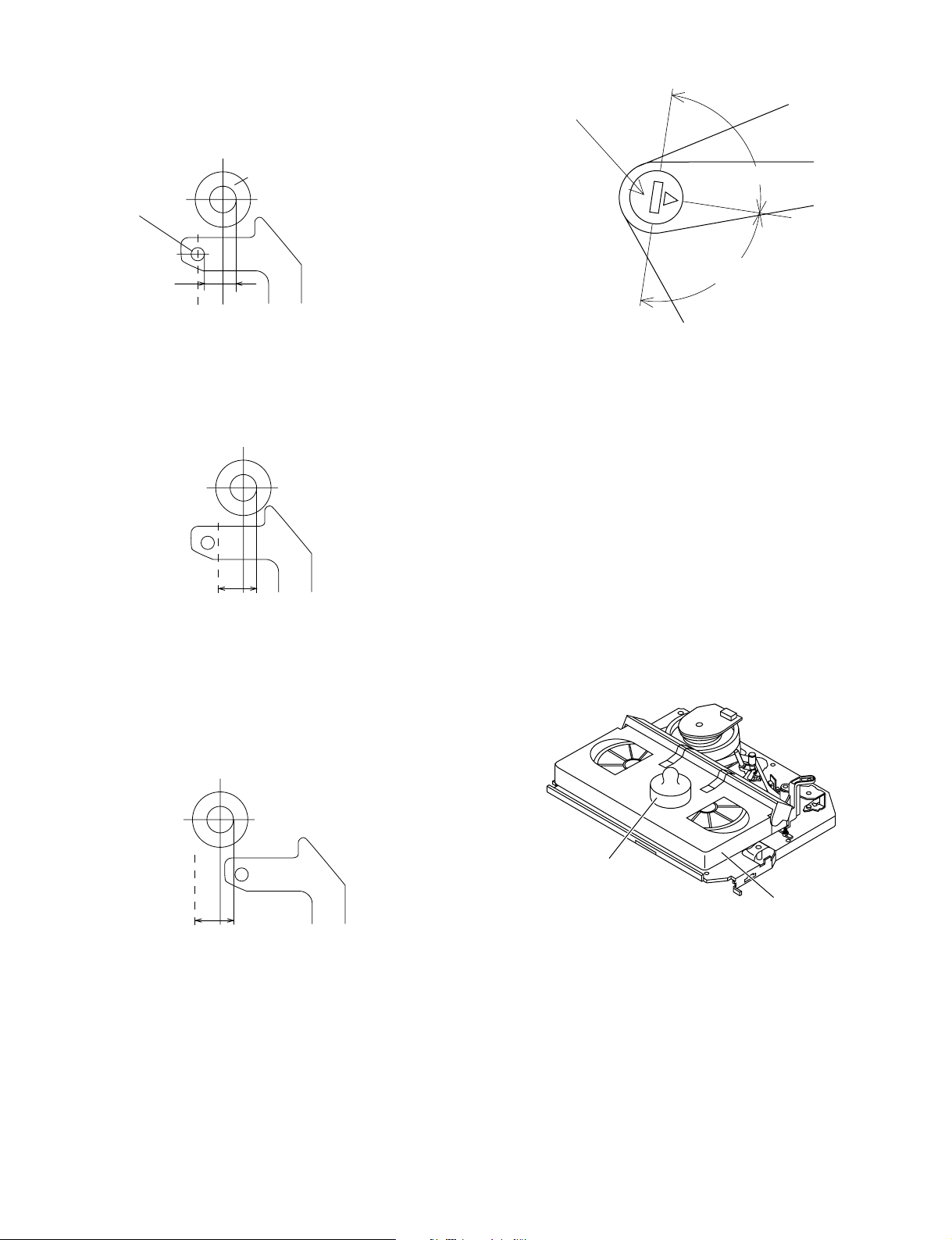
4-15. REPLACEMENT OF A/C (Audio/Control)
HEAD
1. Remove the cassette housing control assembly.
2. In unloading state unplug the power cord.
• Removal
1. Remove the screws 123, Azimuth screw, Tilt screw.
2. Unsolder the PWB fitted to the A/C head.
Notes:
1. When replacing, never touch the head. If you touched,
clean with the cleaning liquid.
2. When removing the screw 3, take care so that the
spring may out.
Tilt screw
3
Azimuth screw
Height screw
Spring
1
3. Align the left end of gear of A/C head arm with the
punched mark of chassis, tentatively tighten the screws
1 and 2 so as to ensure smooth motion of A/C head
arm. Tentative tightening torque must be 0.15 to 0.20
N·m (1.5 to 2.0kgf·cm).
1
3
Height screw
Left end of A/C head arm gear
2
Punched line mark on chassis
Figure 4-25.
Note:
1. If the screws 1 and 2 are tighten tentatively too loose,
the azimuth and height of A/C head may change when
they are finally tightened. Therefore care must be taken.
2. After completion of A/C head be sure to adjust tape
running. (Execute the running adjustment by the method
described in 4-18.)
2
Figure 4-23.
• Replacement
1. Solder the removed PWB to the new head assembly.
2. Adjust the height from the A/C head arm (lower surface)
to the A/C head plate to 10.8mm with slide calipers. (3
places of azimuth screw section, tilt screw section and A/
C head front section) (See the figure below.)
Solder
New A/C head ass'y
A/C head PWB
Never touch the head
A/C head plate
Figure 4-24.
10.8mm10.8mm
20
XA-905
XA-920
4-16. A/C HEAD HEIGHT ROUGH AD-
JUSTMENT
Azimuth screw
Height screw
500g
Weight to prevent
float (500g)
• Setting
1. Set the cassette tape in the unit.
2. Press the PLAY button to put the unit in the playback
mode.
3. Roughly adjust the height of the A/C head by turning the
height screw until the tape is in the position shown
below.
A/C head
Tilt screw
Cassette tape
Mechanism chassis
Figure 4-26.
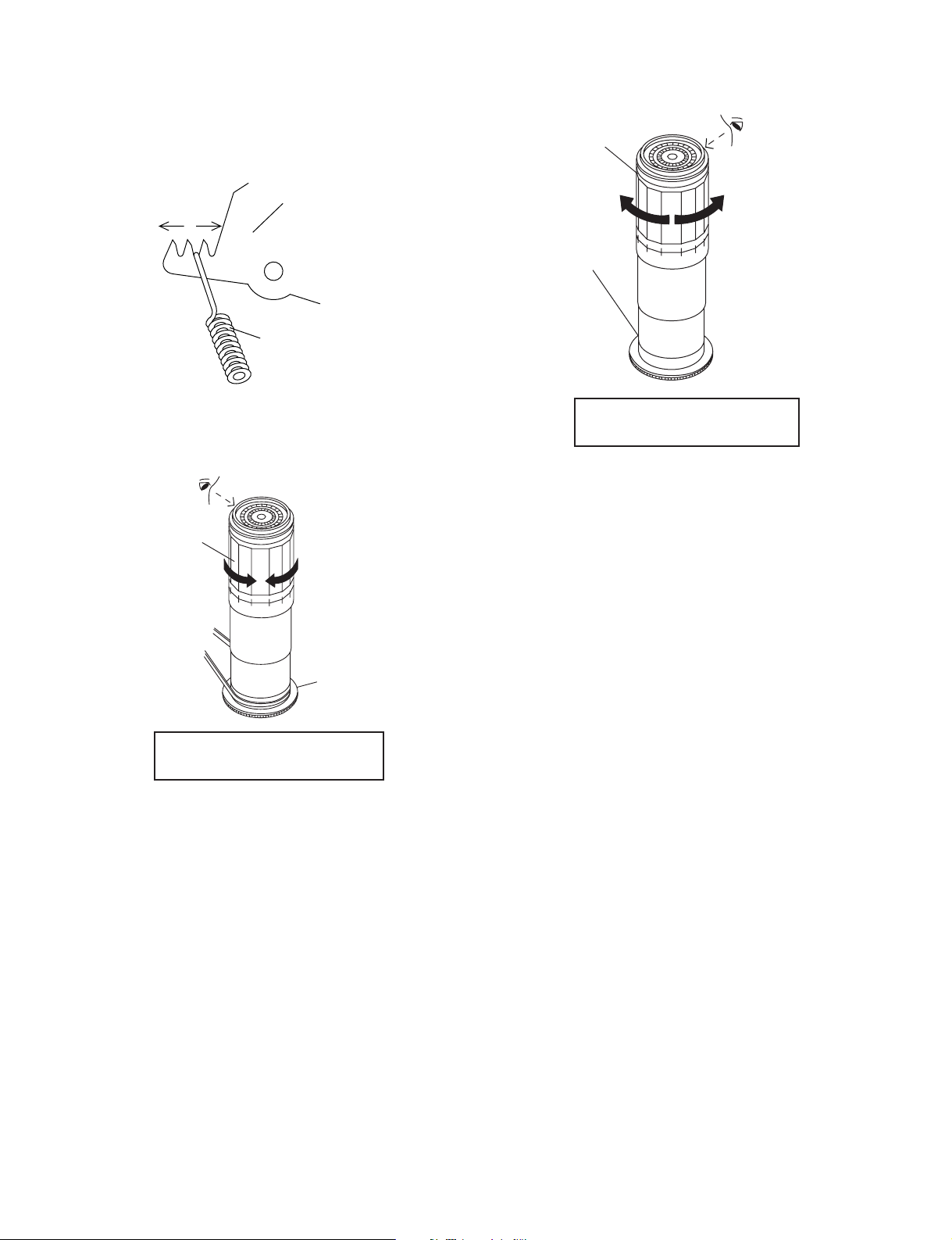
4-17. HEIGHT ADJUSTMENT OF REVERSE
GUIDE
1. Adjust the height from the mechanism chassis to the
reverse guide lower flange to 13.38 mm, using the
reverse guide height adjustment jig, in tape loading
state. (Refer to Figure 4-28 (a) (b).)
Reverse guide
Reverse guide height
adjusting jig
Mechanism
chassis
(a)
Figure 4-28.
2. Rotate counterclockwise the reverse guide height adjustment nut 1/10 turn. (For height adjustment use the
reverse guide height adjustment box driver (JiGDRiVER
11055)).
CCW
Reverse guide height
adjusting jig
13.38mm
(b)
Box driver
Height adjusting nut
Tape
0.3mm
Figure 4-27.
• Adjustment
Adjust the height screw visually so that the control head is
visible 0.3mm below the bottom of the tape.
Figure 4-29.
3. Set the tape, and check for tape crease near the reverse
guide in the playback mode.
If crease is found, turn the reverse guide adjustment nut
to remove crease. (As for crease check refer to Figure 4-
30.)
500g
Weight to
prevent float (500g)
A
Mechanism
chassis
Reverse guide
Capstan
motor shaft
Fixing guide
An example of
crease near the
reverse guide
* Check for crease from the A direction.
Figure 4-30.
21
XA-905
XA-920
4-18. ADJUSTMENT OF TAPE DRIVE TRAIN
1. Tape run rough adjustment
1 Remove the cassette housing control assembly.
2 After shortcircuiting TP803 and TP802 provided at
operation PWB, plug in the power cord.
3 Check and adjust the position of the tension pole.
(See 4-12.)
4 Check and adjust the video search rewind back
tension. (See 4-10.)
5 Connect the oscilloscope to the test point for PB
CHROMA envelope output (TP201). Set the synchronism of the oscilloscope to EXT. The PB
CHROMA signal is to be triggered by the head
switching pulse (TP202).
6 Set the alignment tape (VROATSV) to play. (Put a
500g weight on the cassette tape to prevent lift of
cassette tape.)
Guide roller
Cassette Tape
500g
Weight of 500g
Figure 4-31.
7 Press the tracking button (+), (–) and change the
envelope waveform from max to min and from min to
max. At this time make sure that the envelope
waveform changes nearly parallel.
8 Unless the envelope waveform changes nearly par-
allel, adjust the height of supply side and take-up
side guide roller so that the envelope waveform
changes nearly parallel. (For envelop adjustment
procedure refer to Figure 4-35.)
9 Turn the tilt screw to remove the tape crease at the
fixing guide flange.
Playback the tape and check for tape crease at the
fixing guide flange.
(1)If there is no tape crease
Turn the tilt screw clockwise so that tape crease
appears once at the flange, and then return the tilt
screw so that the crease disappears.
(2)If there is tape crease
Turn counterclockwise the tilt screw so that the
tape crease disappears.
(Reference) If the tilt screw is turned clockwise
crease appears at the lower flange.
Notes:
1. Previously set the tracking control in the center position,
and adjust the envelop waveform to maximum with X
value adjustment nut. Thereby the tape run rough adjustment is facilitated.
2. Especially the outlet side envelope waveform must have
higher flatness.
Figure 4-32.
2. Adjustment of A/C head height and azimuth
1 Perform the initial setting of A/C head position by the
method stated in "4-15 Replacement 3".
2 Connect the oscilloscope to the audio output termi-
nal.
3 Using the alignment tape in which 1 kHz linear audio
signal has been recorded, adjust the height screw so
as to get max audio output.
4 Using the alignment tape in which 7 kHz linear audio
signal has been recorded, adjust the azimuth screw
so as to get max audio output.
5 The adjustment of 3 and 4 twice or three times
repeat, and finally adjust 4.
For X value adjustment
Adjust the X value, turning the geartype screwdriver.
Figure 4-33.
3. Tape run adjustment
1 Connect the oscilloscope to PB CHROMA envelope
output test point, set oscilloscope sync to EXT,
trigger-input the PB CHROMA signal (head switching pulse).
2 Rough adjustment of X value
Tentatively fix A/C head arm screws 1 and 2 by the
method described in 4-15 "Replacement 3".
Playback the alignment tape (VROATSV) and
shortcircuit TP801 and TP802. As a result the autotracking is automatically cancelled, so that the X
value adjustment mode is set.
Move the A/C head with the X value adjustment gear
driver (JiGDRiVER-6) by the method shown in Figure 4-33, and adjust the A/C head so as to get the
maximum envelope waveform. (Note: When the A/
C head is adjusted, adjust so that the maximum
envelop waveform is obtained nearest the position
of initial setting made in 4-15.)
22
3 Next, Press the tracking button (+), (–) and change
CH-1 CH-2
the envelope waveform from max to min and from
min to max. At this time adjust the height of supply
and take-up side guide roller with the adjustment
driver (JiGDRiVERH-4) so that the envelope waveform changes nearly parallel.
4 If the tape is lifted or sunk from the helical lead
surface, the PB CHROMA envelope waveform appears as shown in Figure 4-35.
5 Press the tracking button (+), (–) and make sure that
the envelope waveform changes nearly parallel.
6 Finally check tape crease near the reverse guide. If
tape crease is found, remove it as stated in 4-17
"HEIGHT ADJUSTMENT OF REVERSE GUIDE"
item 3.
Supply side
Take-up side Supply side Take-up side
XA-905
XA-920
PB CHROMA
Envelope
Head switching pulse
Figure 4-34.
4. A/C head X value adjustment
1 Tentatively fix A/C head arm screws 1 and 2 by the
method described in 4-15 "Replacement 3".
2 Playback the alignment tape (VROATSV), and
shortcircuit TP801 and TP802. As a result the autotracking is automatically cancelled, so that the X
value adjustment mode is set.
When the tape is below the helical lead.When the tape is above the helical lead.
Adjustment
Supply side guide roller
rotated in clockwise
direction (lowers guide
roller) to flatten
envelope.
Take-up side guide roller
rotated in clockwise
direction (lowers guide
roller) to flatten
envelope.
Figure 4-35.
3 Move the A/C head with the X value adjustment gear
driver by the method shown in Figure 4-33, and
adjust the A/C head so as to get the maximum
envelope waveform. (Note: At this time adjust so as
to get the maximum envelope waveform nearest the
A/C head position which has been set in case of X
value rough adjustment as stated in 4-18, 3- 2.)
4 Tighten finally the screws 1 and 2. Be sure to
tighten at first the screw 1 and then the screw 2.
Final tightening torque is 0.6N·m (If the screw 2 is
tightened first, the X value may deviate.)
5 Adjust the playback switching point (Refer to the
electric adjustment method.)
6 Playback the self-picture-recorded tape, and check
the flatness of envelope waveform and sound.
Supply side guide roller
rotated in counterclockwise direction (raises
guide roller) to make the
tape float above the helical
lead. The supply
side guide roller is then
rotated in the clockwise
direction to flatten the
envelope.
Take-up side guide roller
rotated in counterclockwise direction (raises
guide roller) to make the
tape float above the
helical lead. The take-up
side guide roller is then
rotated in the clockwise
direction to flatten the
envelope.
Notes:
When the A/C head X value adjustment is performed, be
sure to perform at first X value rough adjustment (refer to 4-
18, 3-2).
2
1
Figure 4-36.
23

XA-905
XA-920
4-19. REPLACEMENT OF THE CAPSTAN D.D.
(DIRECT DRIVE) MOTOR
• Remove the mechanism from the main PWB (refer to 22 "item 1 When removing the mechanism from the main
PWB").
• Removal (Follow the order of indicated numbers.)
1. Remove the reel belt 1.
2. Remove the slow brake lever 2.
3. Remove the three screws 3.
3
Capstan D.D.
motor
Capstan D.D. motor
control PWB
4-20. REPLACEMENT OF DRUM D.D. MOTOR
1. Set the ejection mode.
2. Withdraw the main power plug from the socket.
• Removal (Perform in numerical order.)
1. Disconnect the FFC cable 1.
2. Unscrew the D.D. stator assembly fixing screws 2.
3. Take out the D.D. stator assembly 3.
4. Unscrew the D.D. rotor assembly fixing screws 4.
5. Take out the D.D. rotor assembly 5.
Notes:
1. In removing the D.D. stator assembly, part of the drum
earth spring pops out of the pre-load collar.
Be careful not to lose it.
2. Install, so that the D.D. rotor ass'y and upper drum ass'y
mounting direction check holes align.
(Align the upper drum dent with the rotor hole.)
3. Be careful not to damage the upper drum or the video
head.
4. Protect the hole elements from shock due to contact with
D.D. stator or D.D. rotor ass'y.
5. After installation adjust the playback switching point for
adjustment of servo circuit.
2
1
Reel belt
Slow Brake lever
Figure 4-37-1.
• Reassembly
1. Taking care so that the capstan shaft does not contact
the mechanism chassis, set its position on the mechanism chassis, and then install with the three screws.
2. Install the slow brake lever.
3. Install the reel belt.
Notes:
1. Before installing the capstan D.D. motor, confirm whether
an acetate tape ZTAPEN120020E is drawn on the back
of mechanism chassis.
Stick an acetate tape on the projection part of
the chassis.
Capstan Motor Installation position.
Mechanism Chassis from the back.
2
D.D. stator ass'y
3
4
5
4
D.D. rotor ass'y
1
FFC
Upper drum
Figure 4-38.
Figure 4-37-2.
2. After installing the capstan D.D. motor, be sure to rotate
the capstan D.D. motor and check the movement.
3. Set the tape, and check for the tape crease near the
reverse guide in the playback mode. Adjust the A/C
head and azimuth as stated in 4-18 item 2. If crease is
found, adjust as stated in 4-17 "HEIGHT ADJUSTMENT
OF REVERSE GUIDE".
24
 Loading...