

Page 1
Drive Technology \ Drive Automation \ System Integration \ Services
MOVITRAC
Edition 05/2009
16810813 / EN
®
B
Operating Instructions
Page 2

SEW-EURODRIVE—Driving the world
Page 3

Contents
Phone: 800.894.0412 - Fax: 888.723.4773 - Web: www.clrwtr.com - Email: info@clrwtr.com
Contents
1 Important Information..................................... .................................................... 5
1.1 How to use the operating instructions......................................................... 5
1.2 Structure of the safety notes............................................................ .... ... ... . 6
1.3 Rights to claim under warranty ................................................................... 6
1.4 Exclusion of liability..................................................................................... 6
2 Safety Notes ........................................................................................................ 7
2.1 Preliminary information ............................................................................... 7
2.2 General.......................................................................................................7
2.3 Target group ............................................................................................... 8
2.4 Designated use......... .... ... ... ... .... ... .......................................................... ... . 8
2.5 Other applicable documentation................................................................. 9
2.6 Transport..................................................................................................... 9
2.7 Extended storage........................................................................................ 9
2.8 Installation/assembly................................................................................... 9
2.9 Electrical connection............................................................ ... .................. 10
2.10 Safe disconnection.... .... ... ... ... .... ... .......................................................... .. 10
2.11 Startup/operation ......................................................................................10
3 Unit Design ........................................................................................................ 11
3.1 Sizes 0XS / 0S / 0L................................................................................... 11
3.2 Sizes 1 / 2S / 2..........................................................................................12
3.3 Size 3........................................................................................................ 13
3.4 Sizes 4 / 5 .................................................................................................14
3.5 Unit designation / nameplate .................................................................... 15
4 Installation ......................................................................................................... 16
4.1 Recommended tools.................................................................................16
4.2 Installation notes....................................................................................... 16
4.3 Installing optional power components....................................................... 21
4.4 UL compliant installation...........................................................................26
4.5 Installation of loose items.......................................................................... 28
4.6 Requirements for installing cold plate (size 0 only)................................... 33
4.7 Deactivating EMC capacitors (size 0 only) ...............................................33
4.8 Wiring diagram.......................................................................................... 35
4.9 TF thermistor and TH bimetallic switch..................................................... 36
4.10 Connecting braking resistor BW..-P / BW..-T / BW.. to X3 / X2 ................ 36
4.11 Connecting brake rectifiers ....................................................................... 37
4.12 Installing FSC11B / FIO11B / FIO21B ...................................................... 38
4.13 Installing the MBG11A speed control module...........................................43
System Manual V3 – MOVITRAC® B
3
Page 4

Contents
Phone: 800.894.0412 - Fax: 888.723.4773 - Web: www.clrwtr.com - Email: info@clrwtr.com
5 Startup................................................................................................................ 44
5.1 Brief description of the startup process..................................................... 44
5.2 General startup instructions.......... ...... .... ... ... ... ... .... ... ... ... .... ... ... ... ... .... ..... 45
5.3 Preliminary work and resources................................................................ 46
5.4 Optional keypad FBG11B ......................................................................... 47
5.5 Basic operation of the FBG11B keypad.................................................... 48
5.6 Manual operation with FBG11B speed control module............................ 50
5.7 External setpoint selection........................................................................ 51
5.8 Startup using the FBG11B keypad ........................................................... 52
5.9 Startup with PC and MOVITOOLS
5.10 Startup of explosion-proof AC asynchronous motors of category 2
(94/9/EC)................................................................................................... 56
5.11 Starting the motor ..................................................................................... 57
5.12 Parameter list.......................................... ... ... ... ... .... ... ............................... 61
6 Operation ........................................................................................................... 72
6.1 Data backup..............................................................................................72
6.2 Return codes (r-19 – r-38) ........................................................................ 73
6.3 Status displays.......................................................................................... 74
6.4 Unit status codes ...................................................................................... 75
®
MotionStudio....................................55
7 Service / List of Faults...................................................................................... 76
7.1 Unit information......................................................................................... 76
7.2 List of faults (F-00 – F-113)....................................................................... 78
7.3 SEW electronics service ........................................................................... 81
7.4 Extended storage...................................................................................... 82
8 Technical Data................................................................................................... 83
8.1 CE marking, UL approval and C-Tick ....................................................... 83
8.2 General technical data........... .... ... ... ... .... ... ... ... ... .... ... ... ... ....... ... ... ... .... ... .. 84
8.3 MOVITRAC
8.4 Technical data of MOVITRAC
®
B electronics data ............................................................... 86
®
B.............................................................88
8.5 Front option FBG11B keypad ................................................................. 107
8.6 FSC11B communication module ........ ....... ... ... ... .... ... ... ... .... ... ... ... ... .... ... 108
8.7 FIO11B analog module........................................................................... 109
8.8 FIO21B digital module ............................................................................110
Index................................................................................................................. 111
4
System Manual V3 – MOVITRAC® B
Page 5

How to use the operating instructions
Phone: 800.894.0412 - Fax: 888.723.4773 - Web: www.clrwtr.com - Email: info@clrwtr.com
1 Important Information
1.1 How to use the operating instructions
The operating instructions are an integral part of the product and contain important
information for operation and service. The operating instructions are written for all
employees who assemble, install, startup, and service this product.
The operating instructions must be legible and accessible at all times. Make sure that
staff responsible for the plant and its operation, as well as persons who work independently on the unit, have read the operating instructions carefully and understood them.
If you are unclear about any of the information in this documentation, or if you require
further information, contact SEW-EURODRIVE.
1.1.1 Text Conventions
• Texts in softwa re user interfaces (menu item s, buttons, etc.) in square bracket s, e.g.:
"Click the [Start] button."
• Parameter names are written in italics, e.g.: "Write down the values of variables H509
ACT.POS.ABS.".
Important Information
1
• The display of the FBG11B keypad is indicated by a font with fixed character width,
e.g.: "The display shows Stop."
Operating Instructions V3 – MOVITRAC® B
5
Page 6
1
Phone: 800.894.0412 - Fax: 888.723.4773 - Web: www.clrwtr.com - Email: info@clrwtr.com
Important Information
Structure of the safety notes
1.2 Structure of the safety notes
The safety notes in these operating instructions are designed as follows:
Pictogram
Type and source of danger.
Possible consequence(s) if the safety notes are disregarded.
• Measure(s) to prevent the danger.
Pictogram Signal word Meaning Consequences if
Example:
General danger
Specific danger, such
as electric shock
SIGNAL WORD
disregarded
DANGER Imminent danger Severe or fatal injuries
WARNING Possible dangerous situation Severe or fatal injuries
CAUTION Possible dangerous situation Minor injuries
NOTICE Possible damage to property Damage to the drive system or
its environment
TIP Useful information or tip.
Simplifies the handling of the drive
system.
1.3 Rights to claim under warranty
A requirement of fault-free operation and fulfillment of any rights to claim under limited
warranty is that you adhere to the information in the operating instructions. Therefore,
read the operating instructions before you start working with the unit.
1.4 Exclusion of liability
You must comply with the information contained in these operating instructions to
ensure safe operation of MOVITRAC
specified product characteristics and performance requirements. SEW-EURODRIVE
does not assume liability for injury to persons or damage to equipment or property
resulting from non-observance of these operat ing instructions. In such cases, any liability for defects is excluded.
6
®
B frequency inverters and to achieve the
Operating Instructions V3 – MOVITRAC® B
Page 7
2 Safety Notes
Phone: 800.894.0412 - Fax: 888.723.4773 - Web: www.clrwtr.com - Email: info@clrwtr.com
The following basic safety notes must be read carefully to prevent injury to persons a nd
damage to property. The operator must ensure that the basic safety notes a re read and
observed. Make sure that persons responsible for the plant and its operation, as well as
persons who work independently on the unit, have read through the operating instructions carefully and understood them. If you are unclear about any of the information in
this documentation, or if you require further information, please contact SEWEURODRIVE.
2.1 Preliminary information
The following safety notes predomin antly refer to the use of frequency inverters. Additionally, when using drives with motors or gearmotors, observe the corresponding safety
notes in the respective operating instructions.
Also observe the supplementary safety notes in the individual sections of this publication.
Safety Notes
Preliminary information
2
2.2 General
DANGER
During operation, frequency inverters can have live, bare parts according to their
degree of protection.
Severe or fatal injuries.
• All work related to transportation, storage, setup/mounting, connection, startup,
maintenance and repair may only be carried out by qualified personnel, in strict
observation of:
– The relevant detailed operating instructions
– The warning and safety signs on the motor/gearmotor
– All other project planning documents, operating instructions and wiring
diagrams related to the drive
– The specific regulations and requirements for the system
– The national/regional regulations governing safety and the prevention of
accidents
• Never install damaged products.
• Immediately report any damages to the shipping company.
Removing covers without authorization, improper use as we ll as incorrect in stallation or
operation may result in severe injuries to persons or damage to property.
This document includes further information.
Operating Instructions V3 – MOVITRAC® B
7
Page 8

2
Phone: 800.894.0412 - Fax: 888.723.4773 - Web: www.clrwtr.com - Email: info@clrwtr.com
2.3 Target group
Safety Notes
Target group
Any mechanical work may only be performed by adequately qualified person nel. Qualified personnel in this context are persons who are familiar with the setup, mechanical
installation, trouble shooting and maintenance for this product. Further, they are qualified as follows:
• Training in mechanical engineering, e.g. as a mechanic or mechatronics technician
(final examinations must have been passed).
• They are familiar with these operating instructions.
Any electronic work may only be per form ed by adequately qualified electricians. Qualified electricians in this context are persons who are familiar with the electronic installation, startup, trouble shooting and maintenance for this product. Further, they are qualified as follows:
• Training in electrical engineering, e.g. as an electrician or me chatronics technician
(final examinations must have been passed).
• They are familiar with these operating instructions.
All work in further areas of transportation, storage, operation and waste disposal may be
carried out only by persons who are trained appropriately.
2.4 Designated use
Frequency inverters are components for controlling asynchronous AC motors.
Frequency inverters are components intended for installation in electrical systems or
machines. Never connect capacitive loads. Operation with capacitive loads results in
over voltages and may destroy the unit.
The following standards apply, if the frequency inverters a re mar k eted in th e EU/EF TA:
• In case of installation in machines, startup of the drive inverters (meaning the start of
proper use) is prohibited until it is determined that the machine meets the
requirements stipulated in the EC Directive 98/37/EC (m achine directive); observe
EN 60204.
• Startup (i.e. the start of designated use) is only permitted under observance of the
EMC (2004/108/EC) directive.
• The frequency inverters comply with the requirements of the Low Voltage Directive
2006/95/EC. The harmonized standards of the EN 61800-5-1/DIN VDE T105 series
in connection with EN 60439-1/VDE 0660 part 500 and EN 60146/VDE 0558 are
applied to these frequency inverters.
Observe the technical data and the connection requirements specified o n the nameplate
and the operating instructions.
2.4.1 Safety functions
Frequency inverters from SEW-EURODRIVE must not perform any safety functions
unless the inverters are subordinate to other safety systems.
Use higher-level safety systems to ensure protection of equipment and personnel.
8
Operating Instructions V3 – MOVITRAC® B
Page 9

2.5 Other applicable documentation
Phone: 800.894.0412 - Fax: 888.723.4773 - Web: www.clrwtr.com - Email: info@clrwtr.com
When using the "Safe stop" function, you must observe the following publications:
•MOVITRAC
•MOVITRAC
These publications are available via Documentation\Software\CAD on the SEWEURODRIVE homepage.
®
B / Safe Disconnection – Conditions
®
B / Safe Disconnection – Applications
2.6 Transport
Immediately upon receipt, inspect the shipment for any da mage that may have occurred
during transportation. Inform the shipping company immediately in the even t of damage.
It may be necessary to preclude startup. Observe the climate conditions according to
chapter "General technical data".
Safety Notes
Other applicable documentation
2
2.7 Extended storage
Observe the notes in section "Extended storage".
2.8 Installation/assembly
The units must be installed and cooled according to the regulations and specifications
in this documentation.
Protect the frequency inverters from excessive strain. Do not twist any components and
do not modify the insulation spaces. Do not touch any electronic components or
contacts.
Frequency inverters contain components that can easily be damaged by electrostatic
energy and improper handling. Electric components m ust not be mechanically damaged
or destroyed.
The following applications are prohibited unless the unit is explicitly designed for such
use:
• Use in potentially explosive atmospheres.
• Use in areas exposed to harmful oils, acids, gases, vapors, dust, radiation, etc.
(frequency inverter may only be operated in climate class 3K3 to EN 60721-3-3)
• Use in non-stationary applications which are subject to mechanical vibration and
impact loads in excess of the requirements in EN 61800-5-1.
Operating Instructions V3 – MOVITRAC® B
9
Page 10

2
Phone: 800.894.0412 - Fax: 888.723.4773 - Web: www.clrwtr.com - Email: info@clrwtr.com
Safety Notes
Electrical connection
2.9 Electrical connection
2.10 Safe disconnection
Observe the applicable national accident prevention guidelines when working on live
frequency inverters (e.g. BGV A3 for Germany).
During installation, observe the specifications regarding cable cross sections, fusing and
protective conductor connection. This publication contains additional information.
In this documentation, you will find notes on EMC compliant installation, such as
shielding, grounding, arrangement of filters and routing of lines. The manufacturer of the
system or machine is responsible for maintaining the limits established by EMC legislation.
Protective measures and protection devices must comply with the regulations in force
(e.g. EN 60204 or EN 61800-5-1).
Ground the unit.
The unit meets all requirements for safe disconnection of power and electronic
connections in accordance with EN 61800-5-1. All connected circuits must also satisfy
the requirements for safe disconnection.
2.11 Startup/operation
Systems with integrated frequency inverters must be equipped with additional monitoring and protection devices, as applicable, according to the relevant safety guidelines
and regulations, such as legislation governing technical equipment, accident prevention
regulations, etc.
Do not touch live components or power connections until 10 minutes after disconnecting
the frequency inverters from the supply voltage because there may still be some
charged capacitors. Observe the corresponding labels on the frequency inverter.
Keep all covers and doors closed during operation.
The fact that the status LED and other display elements are no longer illuminated does
not indicate that the unit has been disconnected from the mains and no longer carries
any voltage.
Mechanical blocking or safety functions inside the unit may result in the motor coming
to a standstill. Eliminating the cause of the problem or performing a reset may result in
the drive re-starting automatically. If, for safety reasons, this is not permitted for the
driven machine, disconnect the unit from the supply system before correcting th e error.
10
Operating Instructions V3 – MOVITRAC® B
Page 11
3 Unit Design
P
i
f
kVA
Hz
n
P
i
f
kVA
Hz
n
Phone: 800.894.0412 - Fax: 888.723.4773 - Web: www.clrwtr.com - Email: info@clrwtr.com
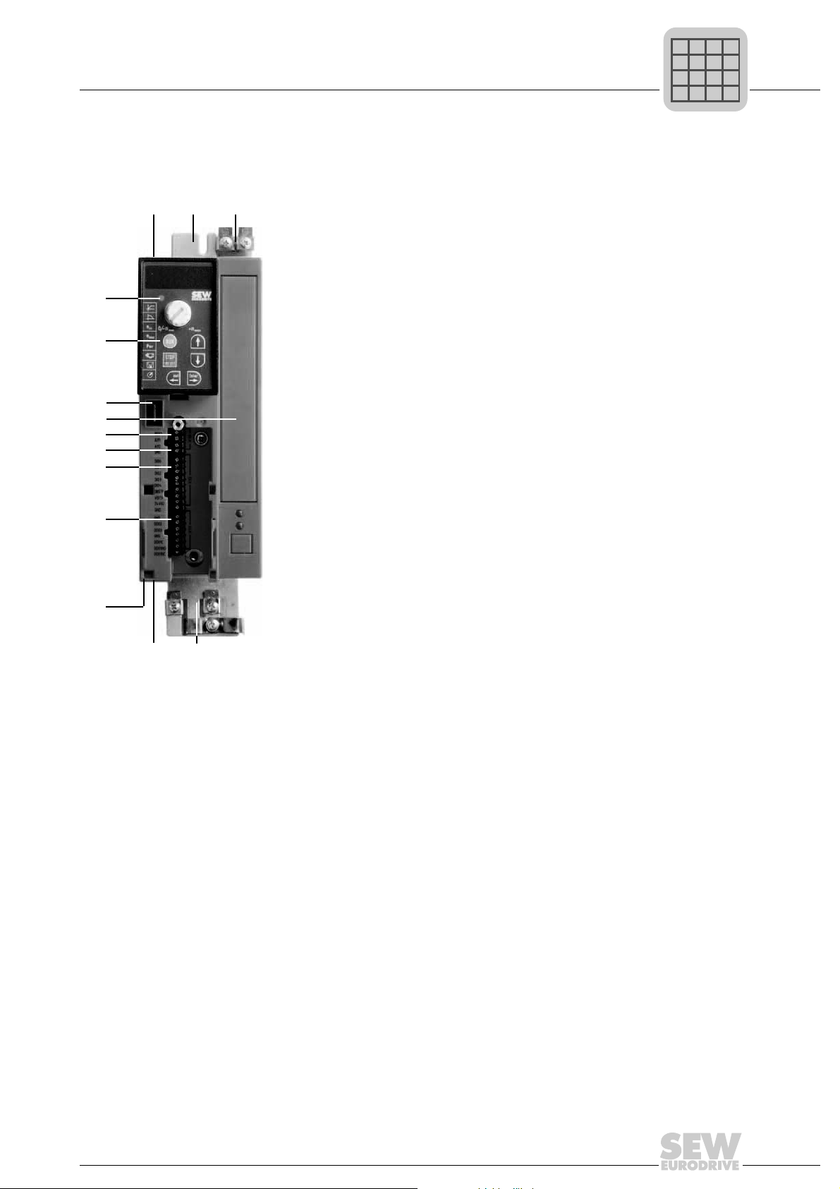
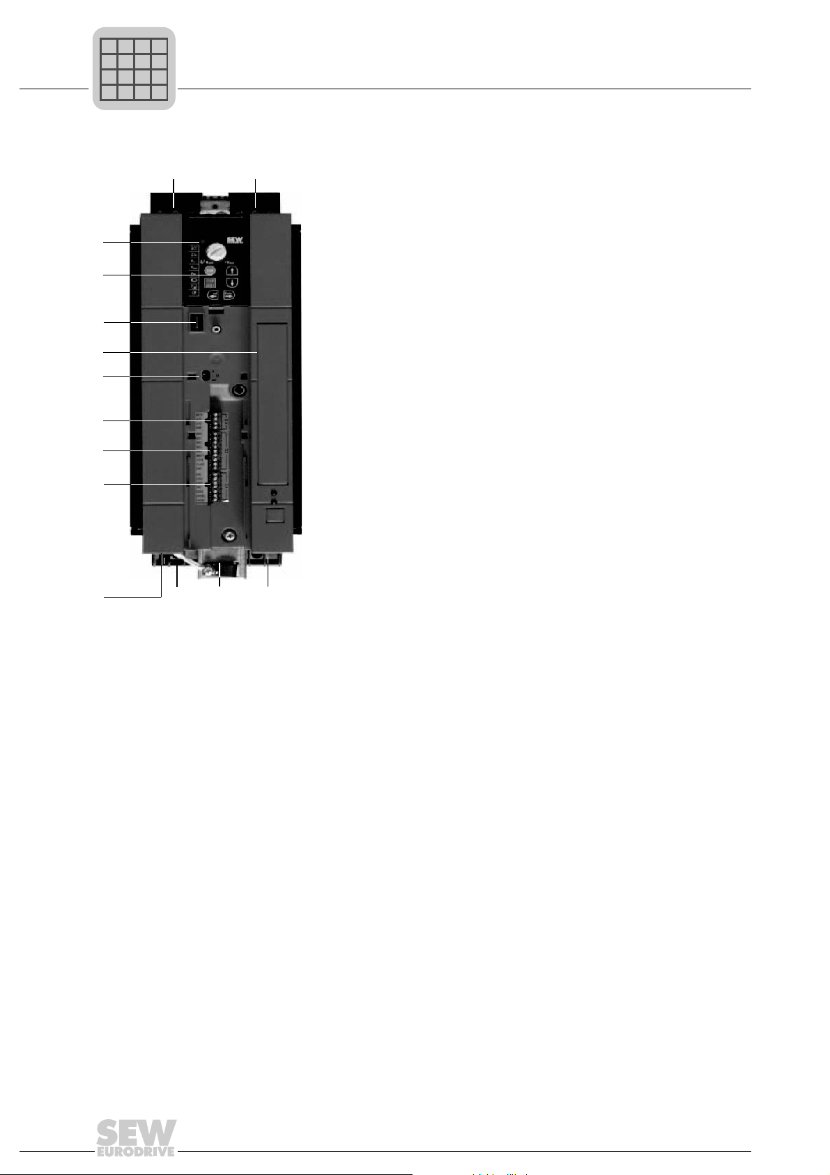
3.1 Sizes 0XS / 0S / 0L
Unit Design
Sizes 0XS / 0S / 0L
3
[14]
[13]
[12]
[11]
[10]
[9]
[8]
[7]
[6]
[1]
[2]
[3]
[4][5]
[1] X1: Power supply connection:
3-phase: L1 / L2 / L3
1-phase: L / N
[2] Fixing strap
[3] PE connection
[4] Shield plate for motor cable, fixing strap underneath
[5] X2: Motor connection U / V / W / Brake connection +R / –R
[6] X17: Safety contact for safe stop (only MC07B...-S0: sizes 0S / 0L, 400 / 500 V)
[7] X13: Binary outputs
[8] X12: Binary inputs
[9] X10: Analog input
[10] Switch S11 for V-mA toggle an a l og in pu t
(in sizes 0XS and 0S behind removable connector)
[1 1] Option card slot (cannot be retrofitted / not for BG0XS)
[12] Connection for optional communication / analog module
[13] Optional keypad, inserted
[14] Status LED (visible without optional keypad)
Operating Instructions V3 – MOVITRAC® B
11
Page 12
3
P
i
f
kVA
Hz
n
P
i
f
kVA
Hz
n
Phone: 800.894.0412 - Fax: 888.723.4773 - Web: www.clrwtr.com - Email: info@clrwtr.com
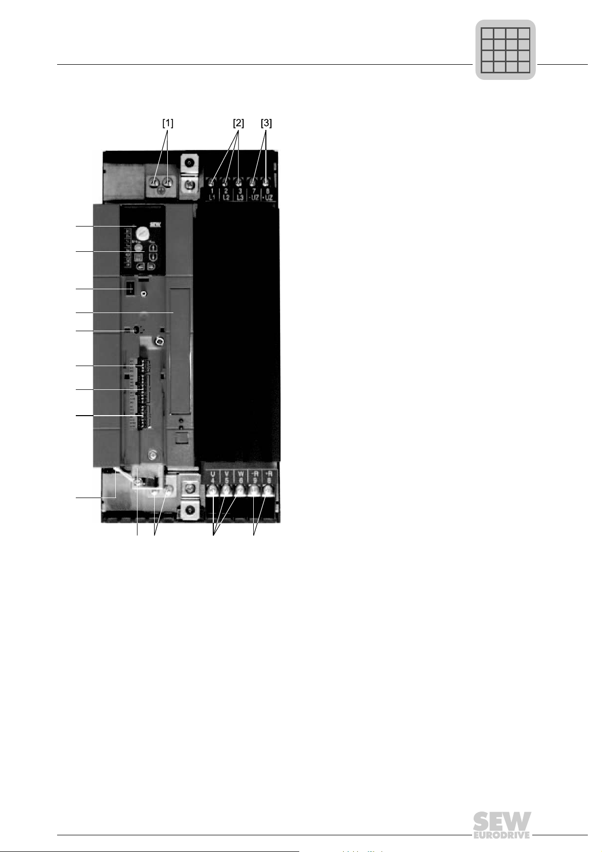
3.2 Sizes 1 / 2S / 2
[14]
[13]
[12]
[11]
[10]
[9]
[8]
Unit Design
Sizes 1 / 2S / 2
[2][1]
[7]
[4]
[1] X1: Power supply connection 3-phase: L1 / L2 / L3 / PE screw
[2] X4: DC link connection –U
[3] X3: Braking resistor connection R+ / R– / PE
[4] Electronics shield clamp
[5] X2: Motor connection U / V / W / PE screw
[6] X17: Safety contact for safe stop (only 400 / 500 V)
[7] X13: Binary outputs
[8] X12: Binary inputs
[9] X10: Analog input
[10] Switch S11 for V-mA toggle an a l og in pu t
[1 1] Option card slot
[12] Connection for optional communication / analog module
[13] Optional keypad, inserted
[14] Status LED (visible without optional keypad)
/ +U
Z
[3][5][6]
Z
12
Operating Instructions V3 – MOVITRAC® B
Page 13
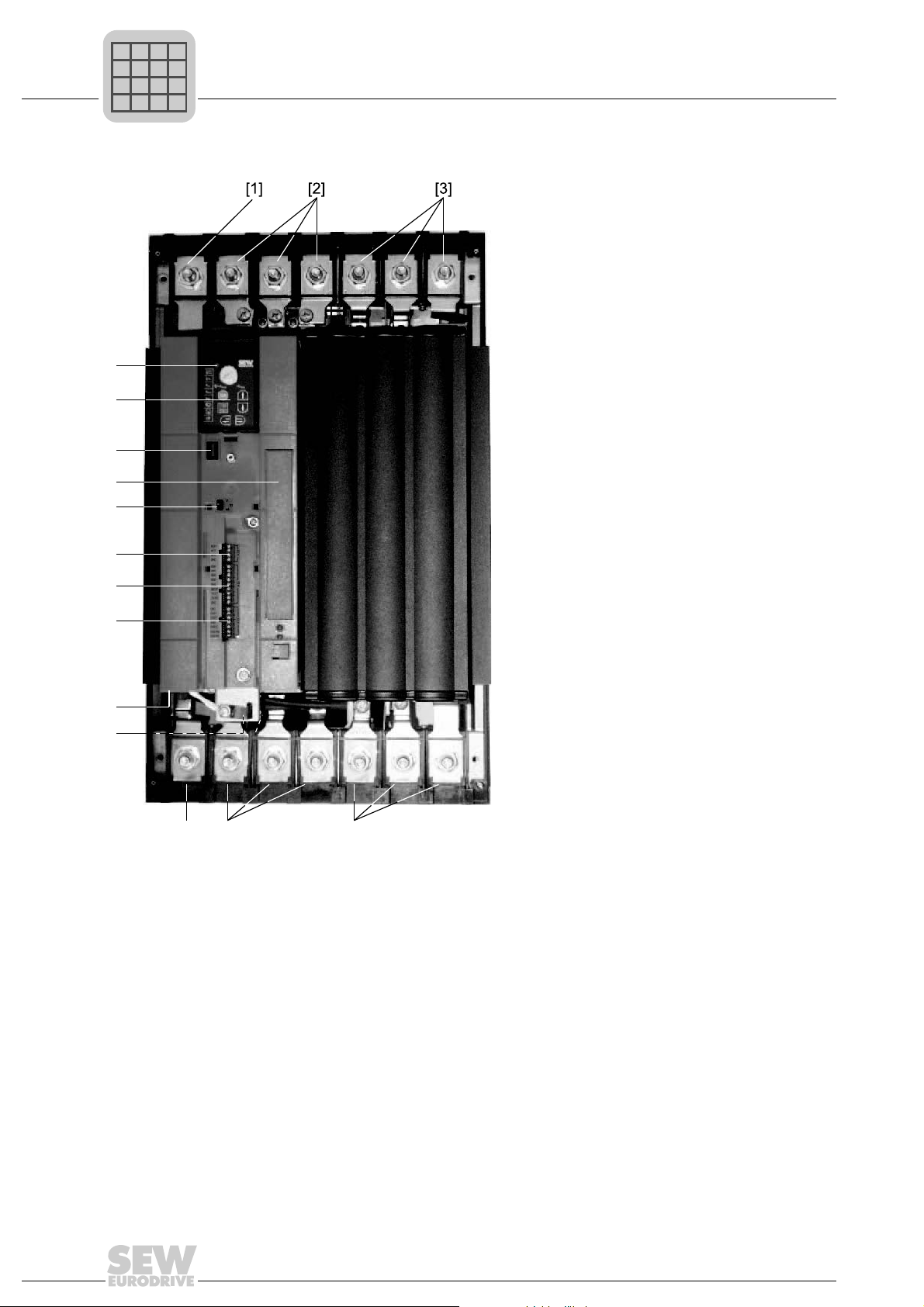
3.3 Size 3
[9]
[10]
[11]
[12]
[13]
[14]
[15]
[16]
[8]
[7]
[4][5][6]
P
i
f
kVA
Hz
n
P
i
f
kVA
Hz
n
Phone: 800.894.0412 - Fax: 888.723.4773 - Web: www.clrwtr.com - Email: info@clrwtr.com
Unit Design
Size 3
3
[1] X2: PE connection
[2] X1: Power supply connection 3-phase: 1/L1 / 2/L2 / 3/L3
[3] X4: DC link connection –U
[4] X3: Braking resistor connection R+ (8) / R– (9) and PE connection
[5] X2: Motor connection U (4) / V (5) / W (6)
[6] X2: PE connection
[7] Electronics shield clamp
[8] X17: Safety contact for safe stop (only 400 / 500 V)
[9] X13: Binary outputs
[10] X12: Binary inputs
[1 1] X10: Analog input
[12] Switch S11 for V-mA toggle an a l og in pu t
[13] Option card slot
[14] Connection for optional communication / analog module
[15] Optional keypad, inserted
[16] Status LED (visible without optional keypad)
Operating Instructions V3 – MOVITRAC® B
/ +U
Z
Z
13
Page 14
3
[6] [4][5]
[9]
[10]
[11]
[12]
[13]
[14]
[15]
[16]
[8]
[7]
P
i
f
kVA
Hz
n
P
i
f
kVA
Hz
n
Phone: 800.894.0412 - Fax: 888.723.4773 - Web: www.clrwtr.com - Email: info@clrwtr.com
3.4 Sizes 4 / 5
Unit Design
Sizes 4 / 5
[1] X2: PE connection
[2] X1: Power supply connection 3-phase: 1/L1 / 2/L2 / 3/L3
[3] X4: DC link connection –U
[4] X3: Braking resistor connection R+ (8) / R– (9) and PE connection
[5] X2: Motor connection U (4) / V (5) / W (6)
[6] X2: PE connection
[7] Electronics shield clamp
[8] X17: Safety contact for safe stop (only 400 / 500 V)
[9] X13: Binary outputs
[10] X12: Binary inputs
[1 1] X10: Analog input
[12] Switch S11 for V-mA toggle an a l og in pu t
[13] Option card slot
[14] Connection for optional communication / analog module
[15] Optional keypad, inserted
[16] Status LED (visible without optional keypad)
14
/ +UZ and PE connection
Z
Operating Instructions V3 – MOVITRAC® B
Page 15

3.5 Unit designation / nameplate
P
i
f
kVA
Hz
n
P
i
f
kVA
Hz
n
Phone: 800.894.0412 - Fax: 888.723.4773 - Web: www.clrwtr.com - Email: info@clrwtr.com
MC 07 B 0022- 2 B 1- 4- 00
Unit Design
Unit designation / nameplate
3
Design
Quadrants 4 = 4Q (with brake chopper)
Connection type 3 = 3-phase / 1 = 1-phase
Radio interference suppression
Supply voltage
Recommended motor power 0022 = 2.2 kW
Version B
Series and generation
MOVITRAC
®
type
00 = Standard
S0 = Safe stop
0 = No radio interference
suppression
A = Radio interference
suppression C2
B = Radio interference
suppression C1
2 = AC 200 – 240 V
5 = AC 380 – 500 V
Input U Rated mains voltage
I Rated mains current, 100 % operation
f Rated mains frequency
Output U Output voltage 100 % operation
I Rated output current 100 % operation
f Output frequency
T Ambient temperature
P motor Recommended motor power 100 % operation
The unit status for communication with SEW-EURODRIVE is indicated over the bar code at the bottom. The
unit status documents the hardware and software states of the unit.
Operating Instructions V3 – MOVITRAC® B
15
Page 16

4
P
i
f
kVA
Hz
n
P
i
f
kVA
Hz
n
Phone: 800.894.0412 - Fax: 888.723.4773 - Web: www.clrwtr.com - Email: info@clrwtr.com
Installation
Recommended tools
4 Installation
4.1 Recommended tools
• Use a screwdriver with a 2.5 mm wide blade for connecting the electronics terminal
4.2 Installation notes
4.2.1 Mounting the front options
strip X10 / X12 / X13.
[A1]
[A]
[A2]
[B2]
[C]
[B]
[B3]
[B4]
[C1]
[B1]
[C2]
Attach the front options as follows:
• Inserting the FBG11A [A] keypad:
1. Insert the FBG11B keypad [A] on top of the housing [A1].
2. Press the socket on the keypad onto the connector in the unit [A2].
• Inserting the FSC11B communication module or the FIO11B analog module [B]:
1. For size 0, mount the spacer bolt [B1] when using the FSC11B communication
module or FIO11B analog module [B].
2. Insert the FSC11B communication module and the FIO11B analog module [B] at
the bottom of the housing [B2].
3. Press the socket on the front option onto the connector in the unit [B3].
4. Secure the front option using the screw on the unit [B4].
• Mounting the cover [C]:
1. Position the cover [C] on the unit approximately 5 mm away from its final position
[C1].
2. Move the cover upwards [C2].
16
Operating Instructions V3 – MOVITRAC® B
Page 17
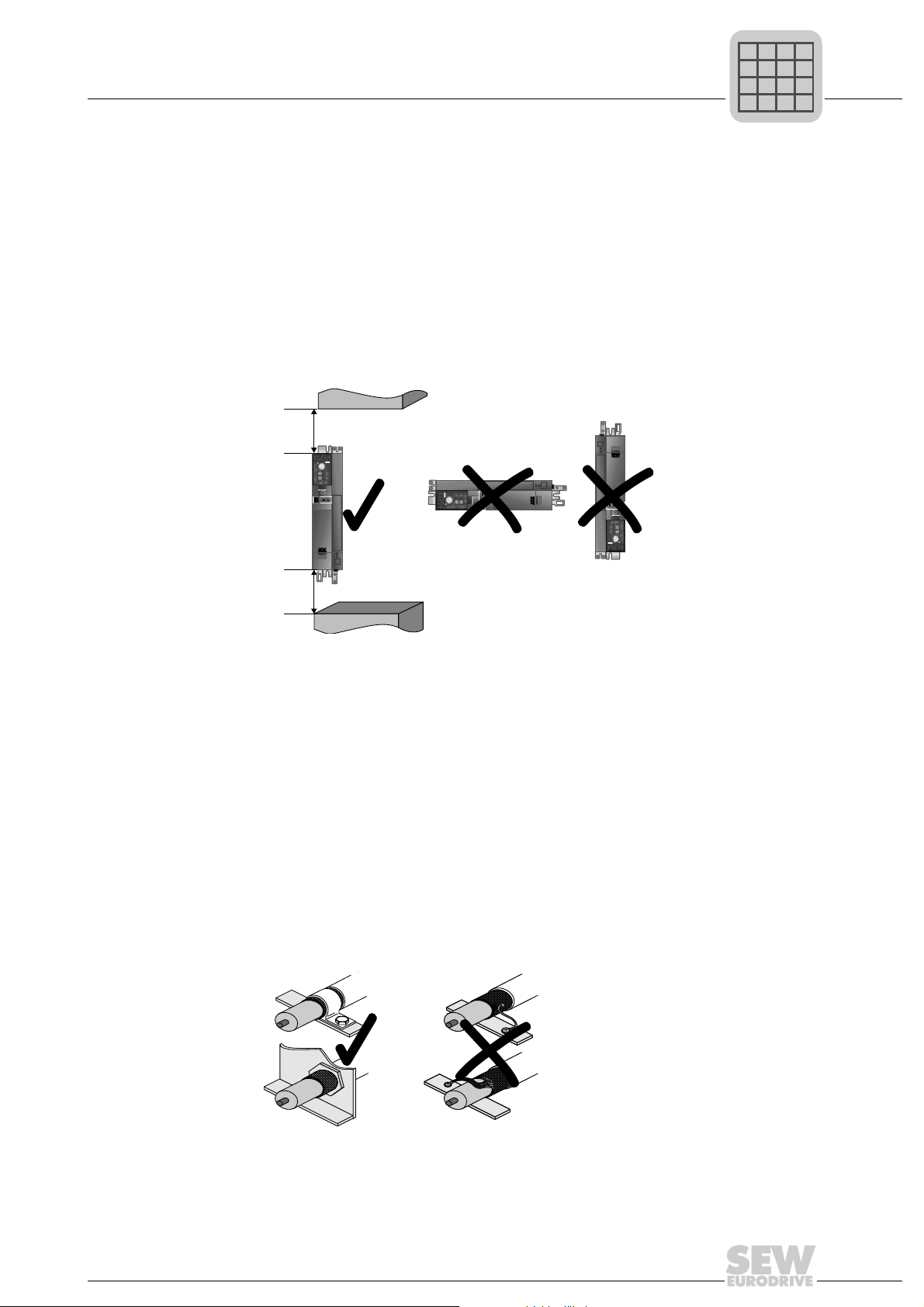
4.2.2 Minimum clearance and mounting position
P
i
f
kVA
Hz
n
P
i
f
kVA
Hz
n
Phone: 800.894.0412 - Fax: 888.723.4773 - Web: www.clrwtr.com - Email: info@clrwtr.com
• Leave 100 mm (3.94 in) clearance at the top and bottom of the housing for optimum
cooling. There is no need for clearance at the sides. You can line up the units directly
next to one another.
• It is important that air circulation is not impeded by cables and other installation
material. Prevent the heated exhaust air from other unit s from blowing onto this unit.
• Install the units vertically only. You must not install them horizontally, tilted or upside
down.
• Proper heat dissipation of the rear side of the heat sink improves the thermal
utilization of the unit.
100 mm
(3.94 in)
Installation
Installation notes
4
100 mm
(3.94 in)
4.2.3 Separate cable ducts
• Route power cables and electronics cables in separate cable ducts.
4.2.4 EMC-compliant installation
• Shield all cables except for the power supply cable. For the motor cable, you can use
the HD.. option (output choke) instead of the shielding to meet the interference
emission limit values .
• When using shielded motor cables, e.g. prefabricated motor cables from SEWEURODRIVE, you must keep the unshielded conductors between the shield and
connection terminal of the inverter as short as possible.
• Connect the shield by the shortest possible route a nd make sur e it is gr ou nde d over
a wide area at both ends. If using double-shielded cables, ground the outer shield on
the inverter end and the inner shield at the other end.
Operating Instructions V3 – MOVITRAC® B
17
Page 18

4
P
i
f
kVA
Hz
n
Phone: 800.894.0412 - Fax: 888.723.4773 - Web: www.clrwtr.com - Email: info@clrwtr.com
4.2.5 Operation on IT systems
4.2.6 Utilization category of contactors
Installation
Installation notes
• You can also use earthed sheet-metal ducts or metal pipes to shield the cables.
Install the power and control cables separately.
• Provide high frequency compatible grounding for the inverter and all additional units
(wide area metal-on-metal contact between the unit housing and ground, e.g.
unpainted control cabinet mounting panel).
• SEW recommends using earth-leakage monitors with a pulse code measuring
process in voltage supply systems with a non-earthed star point (IT systems). Use of
such devices prevents the earth-leakage monitor mis-tripping due to the earth
capacitance of the inverter.
• For size 0, SEW recommends deactivating the interference suppressor filter using
the enclosed insulation discs (see Deactivating EMC capacitors (size 0 only)).
• Use only contactors in utilization category AC-3 (EN 60947-4-1).
4.2.7 Required cross sections
• Power supply cable: Cross section according to rated input current I
load
Motor lead: Cross section according to rated output current I
Electronics cables: Maximum 1.5 mm2 (AWG16) without conductor end sleeves
Maximum 1.0 mm2 (AWG17) with conductor end sleeves
4.2.8 Cable lengths for individual drives
• The cable lengths depend on the PWM frequency . Th e permitted motor cable lengths
are listed in the "Project Planning" section of the MOVITRAC
4.2.9 Unit output
• Only connect an ohmic/inductive load (motor); do not connect a capacitive load!
4.2.10 Braking resistor connection
• Shorten the cables to the required length.
• Use 2 tightly twisted leads or a 2-core shielded power cable. Cross-section according
to the rated output current of the inverter.
at rated
mains
N
®
B system manual.
1)
• Protect the braking resistor with a bimetallic relay with trip class 10 or 10A (wiring
diagram). Set the trip current according to the technical data of the braking resistor.
1) Do not install fine wired cables without conductor end sleeves.
18
Operating Instructions V3 – MOVITRAC® B
Page 19
• For braking resistors in the BW ..-T series, you can connect the integrated thermostat
P
i
f
kVA
Hz
n
Phone: 800.894.0412 - Fax: 888.723.4773 - Web: www.clrwtr.com - Email: info@clrwtr.com
using a 2-core, shielded cable as an alternative to a bimetallic relay.
• The flat-type braking resistors have internal thermal overload protection (fuse cannot
be replaced). Install the flat-design braking resistors together with the appropriate
touch guard.
4.2.11 Installing the braking resistor
• The supply cables to the braking resistors carry a high voltage (approx. DC 900 V)
during rated operation.
• The surfaces of the braking resistors get very hot when the braking resistors are
loaded with P
usually mounted on the control cabinet roof.
4.2.12 Binary outputs
• The binary outputs are short-circuit proof and protected against external voltage to
30 V. Higher external voltages can destroy the binary outputs.
Installation
Installation notes
. Choose a suitable installation location. Braking resistors are
rated
4
4.2.13 Interference emission
• Use shielded motor cables or HD output chokes for EMC compliant installation.
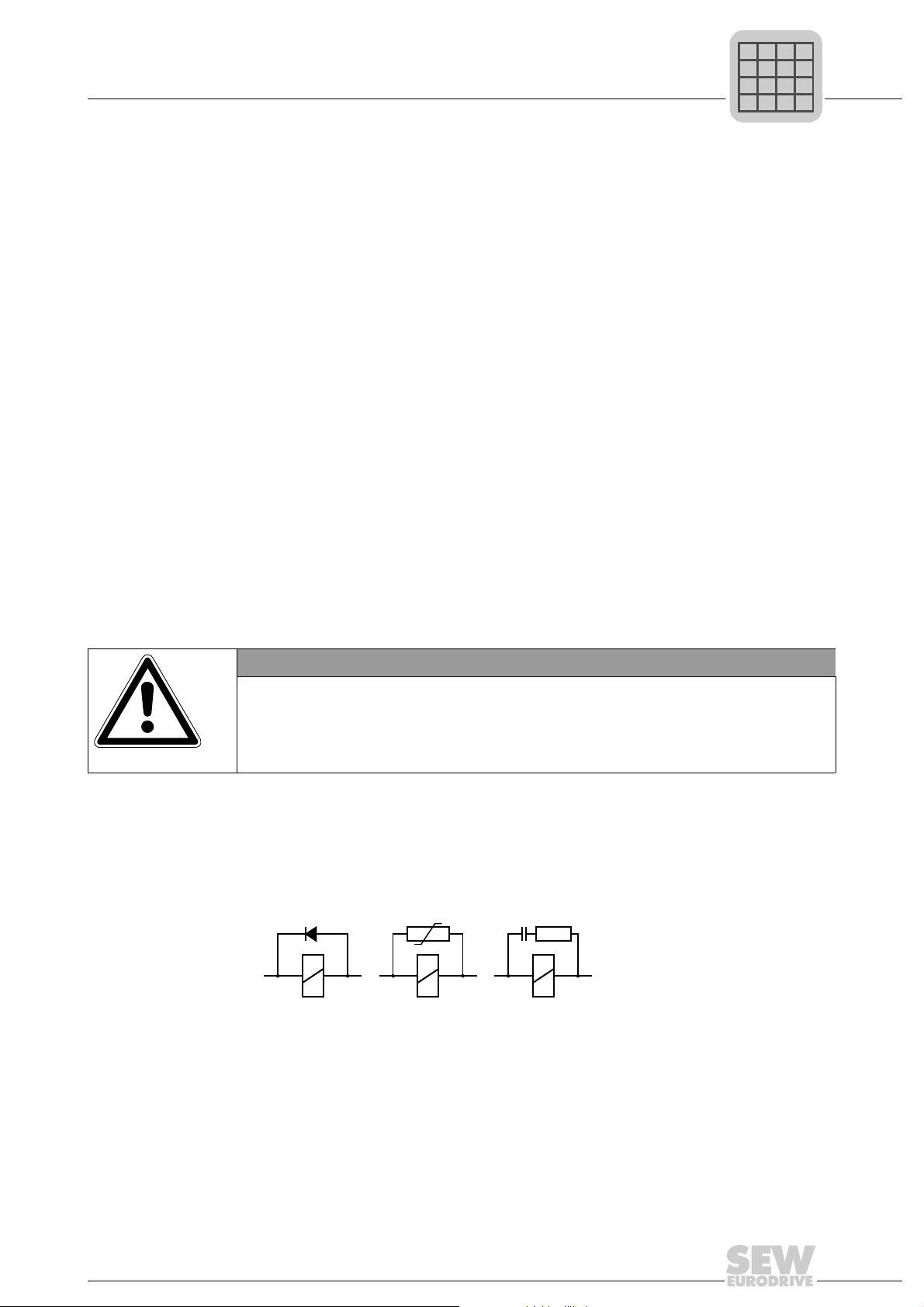
4.2.14 Switched inductances
NOTICE
Switched inductances
Hazard: Malfunctions / damage to property.
Measure: The minimum distance of switched inductances to the inverter must be at
least 150 mm (5.91 in).
• Use suppressors to suppress interference on
– Contactors
–Relays
– Solenoid valves
Suppressors are, for example, diodes, varistors, or RC elements:
®
B. Connect suppressors as
Do not connect any suppressors directly on MOVITRAC
closely as possible to the inductance.
Operating Instructions V3 – MOVITRAC® B
19
Page 20

4
P
i
f
kVA
Hz
n
Phone: 800.894.0412 - Fax: 888.723.4773 - Web: www.clrwtr.com - Email: info@clrwtr.com
4.2.15 Line filters
4.2.16 Line protection and earth-leakage circuit breaker
Installation
Installation notes
®
MOVITRAC
comply with the following limit value class to EN 55011 on the line side without further
measures:
• Single-phase connection: C1 cable conducted
• Three-phase connection: C2
No EMC limits are specified for interference emission in voltage suply systems without
an earthed star point (IT system). The efficiency of line filters is severely limited.
• Install fuses at the beginning of the mains cable behind supply bus junction (see
basic unit wiring diagram).
• SEW-EURODRIVE recommends that you do not use earth-leakage circuit breakers.
However, if an earth-leakage circuit breaker is stipulated for direct or indirect
protection against contact, observe the following:
B frequency inverters have an integrated line filter as standard. They
TIP
Use only type B earth-leakage circuit breakers.
MOVITRAC
leakage circuit breaker is used for protection against direct or indirect contact, only
install a type B earth-leakage circuit breaker on the power supply end of the
MOVITRAC
4.2.17 PE input connect io n
Earth-leakage currents ≥ 3.5 mA may occur during normal operation. Observe the
following for reliable PE connection:
• Power supply cable < 10 mm
– Route a second PE conductor with the same cross section as the power supply
– Use a copper protective earth conductor with a cross section of 10 mm
• Power supply cable 10 mm
– Copper protective earth conductor with the cross section of the power supply
• Power supply cable 16 mm
– Copper protective earth conductor with a cross section of 16 mm
• Power supply cable > 35 mm
®
can cause direct current in the protective earth. In ca ses where an earth-
®
unit.
2
(AWG7):
cable in parallel to the protective earth via separate terminals, or
2
– 16 mm2 (AWG7 – AWG5):
cable.
2
– 35 mm2 (AWG5 – AWG2):
2
(AWG2):
2
2
(AWG5)
(AWG7)
– Copper protective earth co nductor with half the cross section of the power supply
cable.
20
Operating Instructions V3 – MOVITRAC® B
Page 21
Installing optional power components
P
i
f
kVA
Hz
n
Phone: 800.894.0412 - Fax: 888.723.4773 - Web: www.clrwtr.com - Email: info@clrwtr.com
4.3 Installing optional power components
Input contactor for several units
Connect a line choke for limiting the inrush current:
• For 5 or more 3-phase units
• For 2 or more 1-phase units
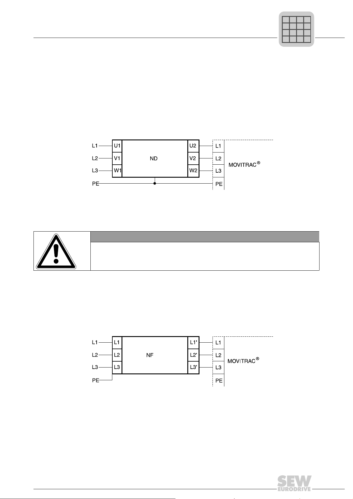
4.3.1 ND line choke
Connecting ND series line choke
Installation
B
4
4.3.2 NF line filter
• Using the NF line filter, you can maintain limit value class C1 / B with MOVITRAC
B sizes 0 to 4.
NOTICE
Possible damage to property
®
No switching is permitted between the line filter and MOVITRAC
• Consequences if disregarded: Damage to the input stage.
• Install the line filter close to the inverter but outside the minimum clearance for
cooling.
• Restrict the cable between the line filter and the inverter to the absolute minimum
length required, and never more than 400 mm (15.7 in). Unshielded, twisted cables
are sufficient.
• Use also unshielded lines for the power supply cable.
Connecting NF line filters
.
B
®
4.3.3 ULF11A folding ferrites
Place the supply system cable (L and N) in the folding ferrite and press the folding
ferrites together until they snap in place.
Compliance with EMC limit class C1 has been tested on a specified test setup.
Compliance with class C1 for signal interference is achieved by the proper installation
of ULF11A folding ferrites.
Operating Instructions V3 – MOVITRAC® B
21
Page 22
4
P
i
f
kVA
Hz
n
Phone: 800.894.0412 - Fax: 888.723.4773 - Web: www.clrwtr.com - Email: info@clrwtr.com
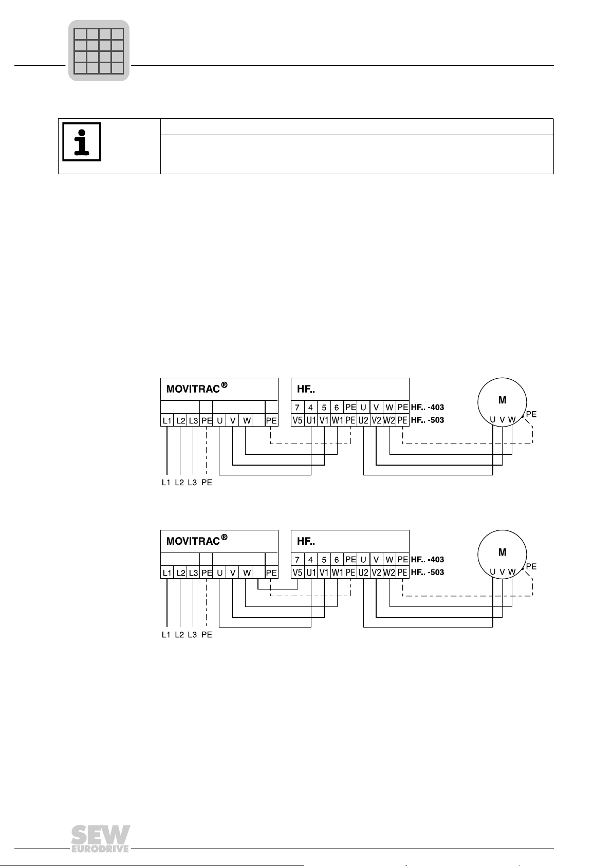
4.3.4 HF output filters
Installation
Installing optional power components
TIP
• Install output filters next to the corresponding inverter . Leave a ventilation space of
at least 100 mm (3.94 in) below and above the output filter. No clearance is
required on the sides.
• Limit the length of the cable between inverter and output filter to the absolute
minimum needed. Maximum 1 m / 3 ft with unshielded cable, 10 m / 33 ft with
shielded cable.
• Several motors can be connected to one output filter when operating a motor group
from one inverter. The total value of the rated motor currents must not exceed the
rated throughput current of the output filter.
• Two identical output filters can be connected in parallel to one inverter output to
double the rated throughput current. To do this, connect all like connections to the
output filters in parallel.
• If you operate the inverter with f
connection V5 (wtih HF..-503) or 7 (with HF..-403).
•No V
HF output filter connection without V
X1
HF output filter connection without V
16 kHz)
X1
connection is permitted for size 0XS units.
DC link
B
X2/3
+R
B
X2/3
+R
= 4 or 8 kHz, do not connect th e output filter
PWM
connection (PWM frequency only 4 or 8 kHz)
DC link
connection (PWM frequency only 12 or
DC link
22
Operating Instructions V3 – MOVITRAC® B
Page 23
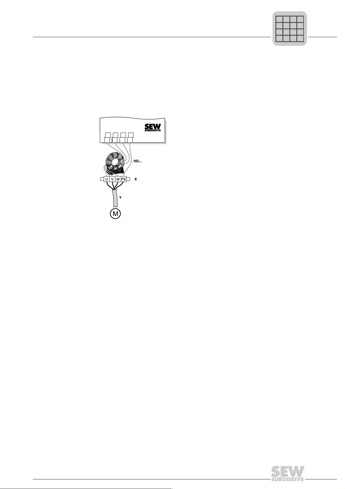
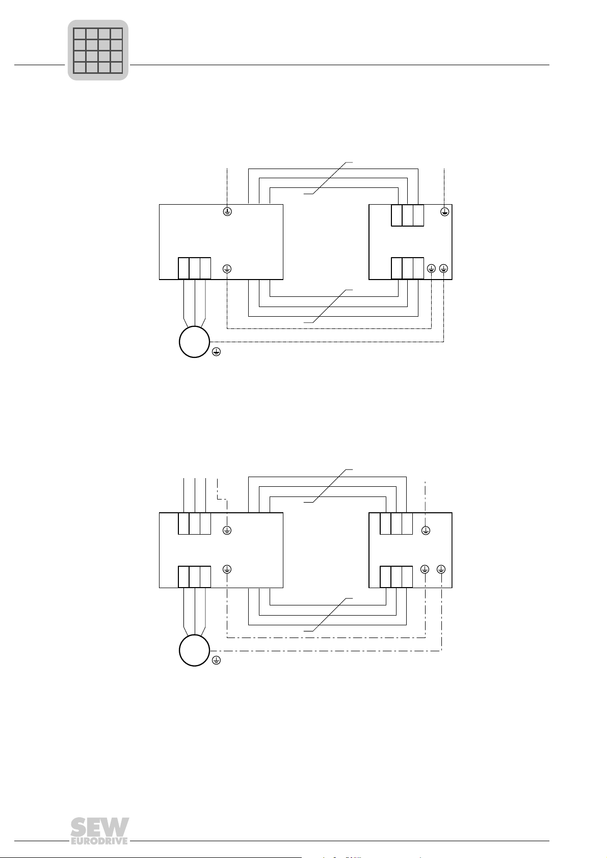
4.3.5 HD output choke
P
i
f
kVA
Hz
n
Phone: 800.894.0412 - Fax: 888.723.4773 - Web: www.clrwtr.com - Email: info@clrwtr.com
• Install the output choke close to MOVITRAC
• Always route all 3 phases (not PE!) through the output choke.
• If the cable is shielded, the shield should not be routed through the output choke.
Installation
Installing optional power components
®
B beyond the minimum clearance.
When using the HD output choke, you have to wrap the cable around the choke 5
times.
4
456
UVWPE
n = 5
Only 5 loops are possible if the cable has a large diameter. To make up for this, 2 or
3 output chokes should be connected in series. SEW recommends connecting in
series 2 output chokes in case of 4 windings and 3 output chokes in case of 3
windings.
• Installing HD012 output choke:
Install the output choke under the associated inverter. Leave a ventilation space of
at least 100 mm (3.94 in) below and above the output choke. Provide a clearance of
10 mm (0.39 in) on each side.
댷
Three alternative connection options are provided for connecting the protective
earth. You can connect the PE line of the motor cable directly on the frequency
inverter.
Operating Instructions V3 – MOVITRAC® B
23
Page 24
4
U V W
PE
M
3
~
HD100 / HD101
L1 L2 L3
U V W
MOVITRAC® B
PE
PE
PE
P
i
f
kVA
Hz
n
Phone: 800.894.0412 - Fax: 888.723.4773 - Web: www.clrwtr.com - Email: info@clrwtr.com
Installation
Installing optional power components
Installing output
choke HD100 /
HD101
4.3.6 FKE12B / FKE13B EMC-modules
Use the supplied screws to mount the HD100 / HD101 output choke together with the
MOVITRAC B frequency inverter onto the conductive mounting surface in the control
cabinet.
The connections U / V / W are labeled U / V / W and have to be connected accordingly.
Use the supplied screws to mount the EMC module together with the MOVITRAC
frequency inverter onto the conductive mounting surface in the control cabinet.
The connections U / V / W are labeled U / V / W and have to be connected accordingly.
®
B
The connections L1 / L2 / L3 (brown / orange / white) can be connected in any order.
L1L2 L3
FKE
U V W
M
3
~
PE
PE
L1L2 L3
MOVITRAC® B
U V W
PE
PE
24
Operating Instructions V3 – MOVITRAC® B
Page 25
Installing optional power components
[1]
[2]
FKB11B
FKB12B
FKB13B
FHS11B
FHS12B
FHS13B
P
i
f
kVA
Hz
n
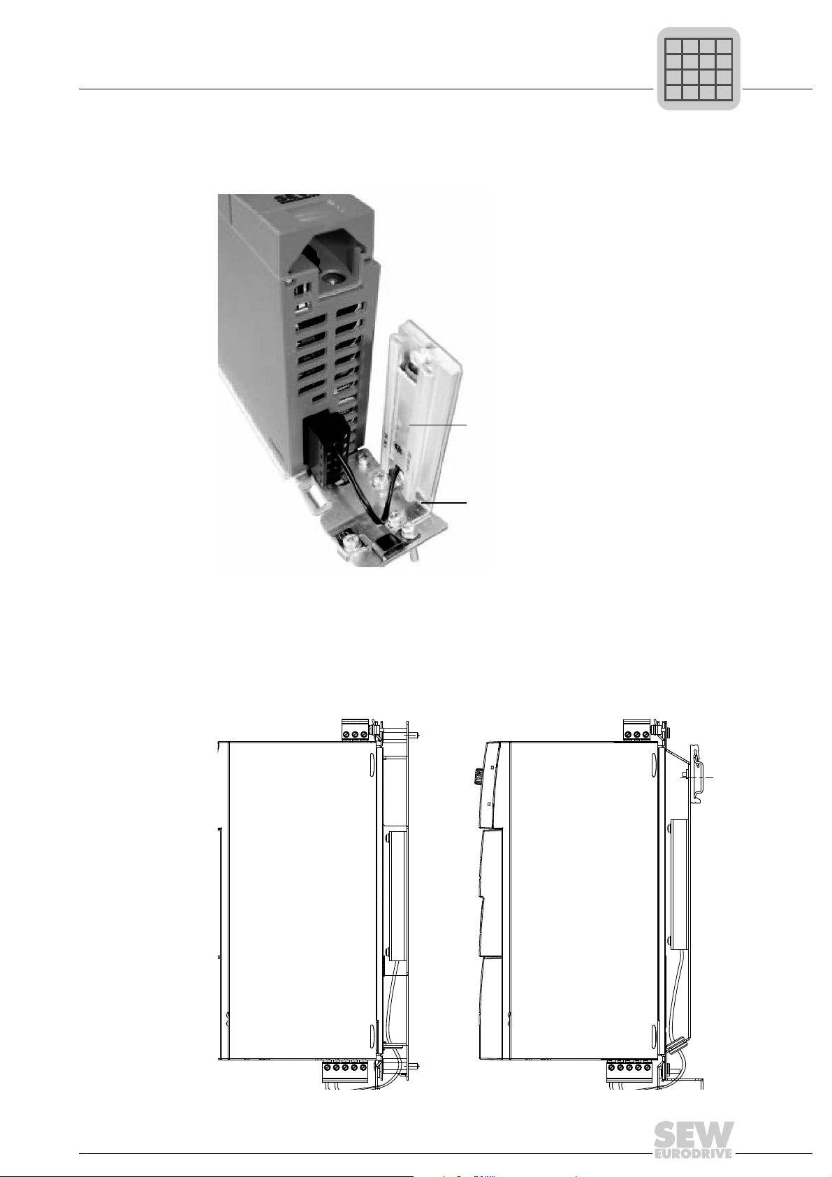
4.3.7 PTC braking resistors BW1 / BW3 with FKB10B
BW1 and BW3 PTC braking resistors [1] can be mounted to the shield plate under the
inverter using the angle bracket FKB10B [2], part number 18216218 available as option.
Installation
4
4.3.8 Flat-design resistors with FKB11B / FKB12B / FKB13B and FHS11B / FHS12B / FHS13B
Flat-design braking resistors can be installed as follows:
• Installation on the back panel of the control cabinet: FKB11B / FKB12B / FKB13B
• Installation with mounting rail: FHS11B / FHS12B / FHS13B
Operating Instructions V3 – MOVITRAC® B
25
Page 26

4
P
i
f
kVA
Hz
n
Phone: 800.894.0412 - Fax: 888.723.4773 - Web: www.clrwtr.com - Email: info@clrwtr.com
Installation
UL compliant installation
4.4 UL compliant installation
Note the following points for UL-compliant installation:
• Only use copper cables with the following temperature rang es as connection cabl es:
–MOVITRAC
–MOVITRAC
• Necessary tightening torques of MOVITRAC
• Operate the inverters on supply systems with a maximum phase-to-earth voltage of
AC 300 V only.
• The inverter can only be operated on IT systems if the phase-to-earth voltage of
AC 3 00 V ca nno t be ex ce ed ed eith er du rin g op er at ion or in case of an er ro r.
•MOVITRAC
systems which can supply maximum values in accordance with the following table.
Only use melting fuses. The performance data of the fuses must not exceed the
values in the following table.
®
B 0003 – 0300: Temperature range 60/75 °C (140/167 °F)
®
B 0370 and 0450: Temperature range 75 °C (167 °F)
®
B power terminals: See technical data.
®
B frequency inverters are only allowed to be operated on supply
26
Operating Instructions V3 – MOVITRAC® B
Page 27
4.4.1 Maximum values/fuses
P
i
f
kVA
Hz
n
Phone: 800.894.0412 - Fax: 888.723.4773 - Web: www.clrwtr.com - Email: info@clrwtr.com
The following maximum values/fuses must be observed for UL compliant installation:
230 V units / 1-phase Max. mains current Max. mains voltage Fuses
0003 / 0004 / 0005 / 0008 AC 5000 A AC 240 V 15 A / 250 V
0011 / 0015 / 0022 AC 5000 A AC 240 V 30 A / 250 V
230 V units / 3-phase Max. mains current Max. mains voltage Fuses
0003 / 0004 / 0005 / 0008 AC 5000 A AC 240 V 15 A / 250 V
0011 / 0015 / 0022 AC 5000 A AC 240 V 20 A / 250 V
0037 AC 5000 A AC 240 V 30 A / 250 V
0055 / 0075 AC 5000 A AC 240 V 110 A / 250 V
0110 AC 5000 A AC 240 V 175 A / 250 V
0150 AC 5000 A AC 240 V 225 A / 250 V
0220 / 0300 AC 10000 A AC 240 V 350 A / 250 V
400/500 V units Max. mains current Max. mains vo ltage Fuses
0003 / 0004 / 0005 / 0008 /
0011 / 0015
0022 / 0030 / 0040 AC 5000 A AC 500 V 20 A / 600 V
0055 / 0075 AC 5000 A AC 500 V 60 A / 600 V
0110 AC 5000 A AC 500 V 110 A / 600 V
0150 / 0220 AC 5000 A AC 500 V 175 A / 600 V
0300 AC 5000 A AC 500 V 225 A / 600 V
0370 / 0450 AC 10000 A AC 500 V 350 A / 600 V
0550 / 0750 AC 10000 A AC 500 V 500 A / 600 V
Installation
UL compliant installation
AC 5000 A AC 500 V 15 A / 600 V
4
TIPS
• Use only tested units with a limited output voltage (V
output current (I ≤ 8 A) as an external DC 24 V voltage source.
• UL certification does not apply to operation in voltag e supply systems with a nongrounded star point (IT systems).
= DC 30 V) and limited
max
Operating Instructions V3 – MOVITRAC® B
27
Page 28
4
"#!#%!#
#!"#%#
"#$!"&"#%&"
P
i
f
kVA
Hz
n
Phone: 800.894.0412 - Fax: 888.723.4773 - Web: www.clrwtr.com - Email: info@clrwtr.com
Installation
Installation of loose items
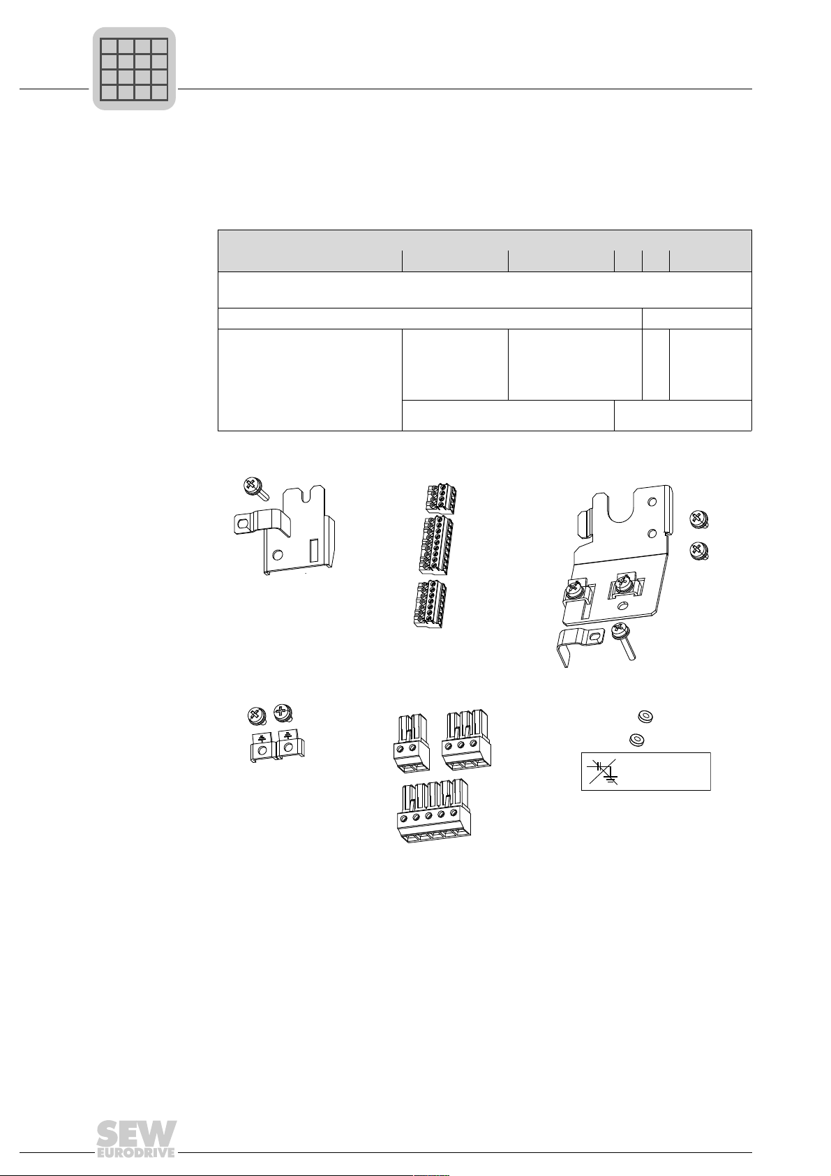
4.5 Installation of loose items
4.5.1 Scope of delivery of loose items
The scope of delivery includes a bag for loose items. Its contents depends on the size
of the inverter.
• Shield plate for control electronics with clamps and screws [1]
• 3 connectors for electronics terminals [2]
• Grounding terminals with screws [4] –
• Shield plate for the power
section with clamps and
screws [3]
• Connector for mains (2 or
3-pole) and motor [5]
• Plastic insulation s with
stickers [6]
Loose items for size 0:
Scope of delivery of loose items for size
0XS / 0S / 0L 1 2S 2 3 4 / 5
• Shield plate
for the power
section
without
screws
• Fixing straps –
• Touch guard
• Shield plate for
the power section
with screws
– • Touch
guard
28
Operating Instructions V3 – MOVITRAC® B
Page 29
Installation
[1]
P
i
f
kVA
Hz
n
Phone: 800.894.0412 - Fax: 888.723.4773 - Web: www.clrwtr.com - Email: info@clrwtr.com
Installation of loose items
4.5.2 Installing shield plate for cont rol electronics (all sizes)
®
MOVITRAC
ics with a retaining screw as standard. Install the shield plate for
control electronics as follows:
1. Loosen the screw first [1].
2. Insert the shield clamp into the slot in the plastic housing.
3. Fasten the shield clamp.
4.5.3 Installing shield plate for power section
Size 0 A power shield plate for the power section with 2 retaining screws is supplied as
standard with MOVITRAC
B includes a shield plate for the control electron-
®
size 0.
4
Mount the shield plate for the power section using the two retaining screws.
[1]
[2]
[1] PE connection [2] Shield plate
Operating Instructions V3 – MOVITRAC® B
29
Page 30
4
P
i
f
kVA
Hz
n
Phone: 800.894.0412 - Fax: 888.723.4773 - Web: www.clrwtr.com - Email: info@clrwtr.com
Installation
Installation of loose items
Size 1 SEW-EURODRIVE supplies a shield plate for the power section as standard with
MOVITRAC
retaining screws.
[1] Shield clamp [2] PE connection
®
B size 1. Mount the shield plate for the power section using the unit's two
[1]
[2]
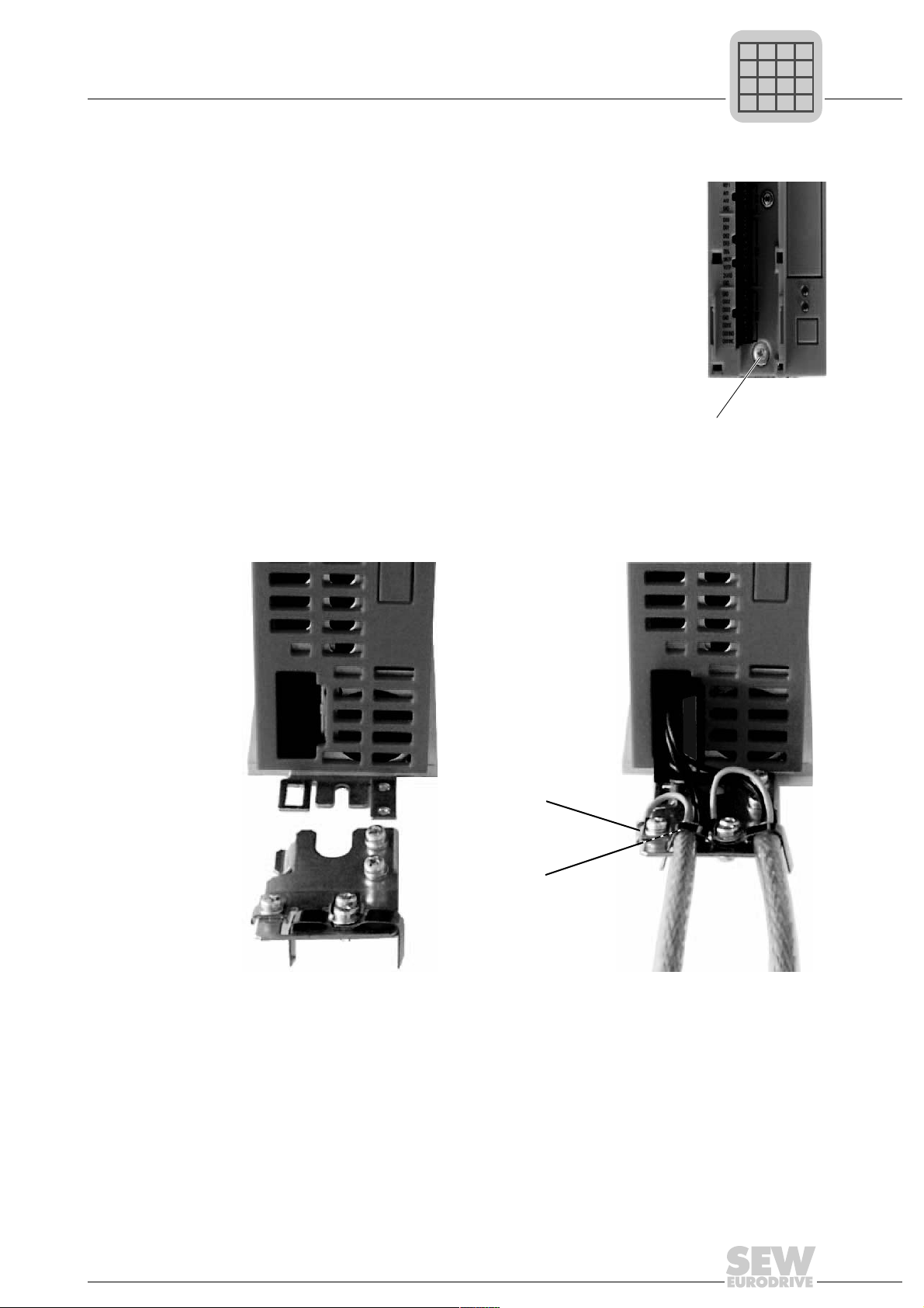
Sizes 2S / 2 SEW-EURODRIVE supplies a shield plate for the power section with two retaining
screws as standard with MOVITRAC
power section using the two retaining screws. The illustration shows size 2.
[1] Shield clamp [2] PE connection
The shield plate for the power section provides you with a very convenient way of installing the shield for the motor and brake cables. Apply the shield and PE conductor as
shown in the figures below.
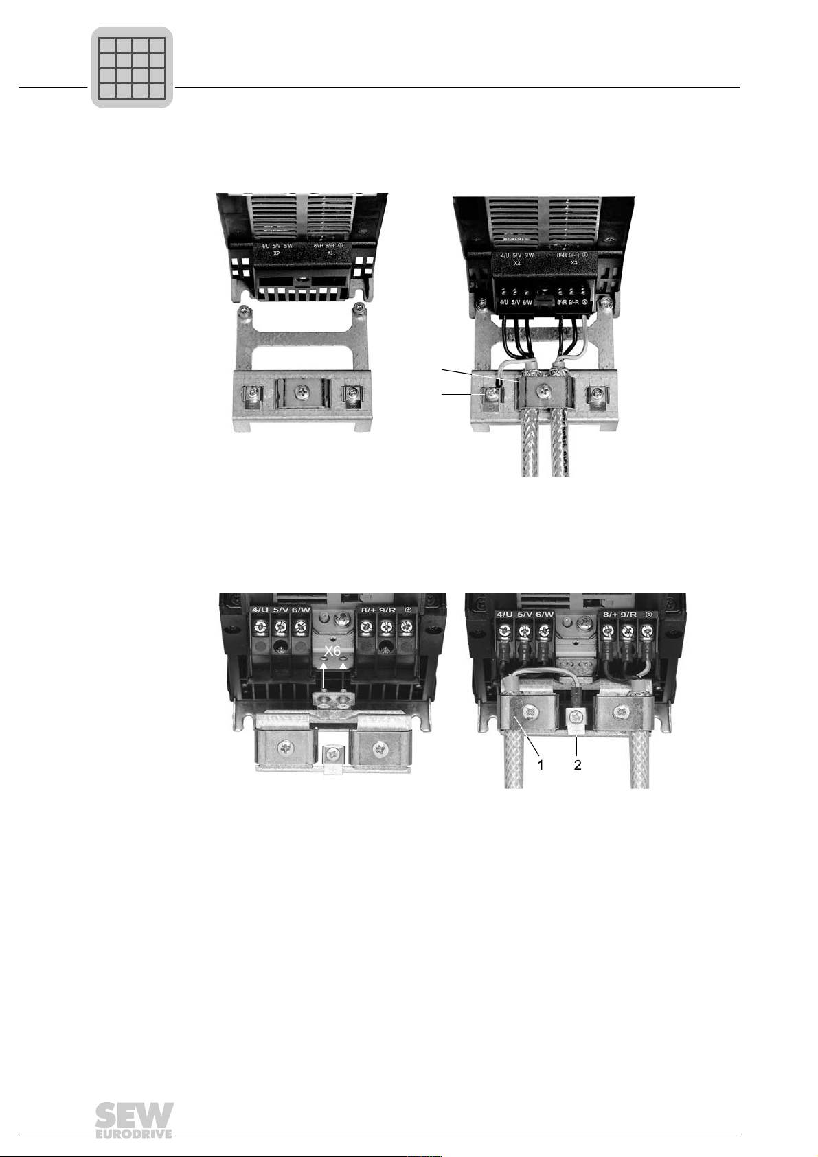
Sizes 3 – 5 No shield plates for the power section are supplied with MOVITRAC
commercially available shield clamps for installing the shielding of motor and brake
cables. Apply the shield as closely as possible to the inverter.
®
B sizes 2S / 2. Mount the shield plate for the
®
B sizes 3 to 5. Use
30
Operating Instructions V3 – MOVITRAC® B
Page 31

4.5.4 Installing the touch guard
P
i
f
kVA
Hz
n
Phone: 800.894.0412 - Fax: 888.723.4773 - Web: www.clrwtr.com - Email: info@clrwtr.com
DANGER
Uncovered power connections.
Severe or fatal injuries from electric shock.
• Install the touch guard according to the regulations.
• Never start the unit if the touch guard is not installed.
Installation
Installation of loose items
4
Size 2S SEW-EURODRIVE supplies two touch guards for the DC link and braking resistor
terminals as standard with MOVITRAC
®
B size 2S. Without touch guard, MOVITRAC
B size 2S has degree of protection IP10. When the touch guard is installed, the unit has
degree of protection IP20.
Install the touch guard as shown in this illustration:
IP10
X4
+U
-U
PE
Z
Z
IP20
X4
-U
+U
PE
Z
Z
IP10
X3
9/-R8/+R
PE
®
IP20
X3
9/-R8/+R
PE
Operating Instructions V3 – MOVITRAC® B
31
Page 32

4
[1]
[2]
[3]
P
i
f
kVA
Hz
n
Phone: 800.894.0412 - Fax: 888.723.4773 - Web: www.clrwtr.com - Email: info@clrwtr.com
Sizes 4 / 5 Two touch guards with 8 retaining screws are supplied as standard with MOVITRAC® B
Installation
Installation of loose items
sizes 4 / 5. Install the touch guard on both covers of the power section terminals.
®
Touch guard for MOVITRAC
B sizes 4 / 5:
The touch guard comprises the following parts:
[1] Cover plate
[2] Connection plate
[3] Screen (only for size 4)
MOVITRAC
following conditions are met:
• Touch guard is fully installed
• The shrink tubing is installed on all power terminals (X1, X2, X3, X4)
TIP
If the above conditions are not met, MOVITRAC
protection IP00.
®
B unit sizes 4 / 5 can only achieve degree of protection IP10 when the
®
unit sizes 4 and 5 have degree of
32
Operating Instructions V3 – MOVITRAC® B
Page 33

Requirements for installing cold plate (size 0 only)
P
i
f
kVA
Hz
n
Phone: 800.894.0412 - Fax: 888.723.4773 - Web: www.clrwtr.com - Email: info@clrwtr.com
4.6 Requirements for installing cold plate (size 0 only)
The frequency inverter power loss can be dissipated via coolers that work with different
cooling media (air, water, oil, etc.). This can be useful, for example, in restricted installation spaces. When adhering to the usual installation notes (40 °C (104 °F) / 100 mm
(3.94 in) space above and below), cold-plate technology is not necessary.
A good thermal connection to the cooler is important for safe operation of the frequency
inverters:
• The contact area between cooler and frequency inverter has to be the size of the
frequency inverter cooling plate.
• Level contact surface, deviation max. up to 0.05 mm (0.0002 in).
• Connect cooler and cooling plate with all necessary screw connections.
• The mounting plate must not exceed 70 °C (158 °F) during operation. This must be
ensured by the cooling medium.
• Cold plate installation is not possible with FHS or FKB.
Installation
4
4.7 Deactivating EMC capacitors (size 0 only)
Only electricians are allowed to convert the unit. Once converted, the unit must be
marked with the sticker provided in the accessory bag.
DANGER
Severe or fatal injuries from electric shock.
• Disconnect the inverter from the power. Switch off the DC 24 V and the mains
voltage.
• Wait 10 seconds.
• Ensure that the unit is de-energized.
• Take appropriate measures to avoid electrostatic charges (use discharge strap,
conductive shoes, etc.) before removing the cover.
• Touch only the unit frame and heat sink. Do not touch any electronic components.
Proceed as follows to deactivate the EMC capacitors for MOVITRAC
1. Open the unit:
– Remove all connectors.
– Remove the electronics shield clamp.
– Remove the housing retaining screw in the center of the housing front.
– Remove the housing.
®
B:
Operating Instructions V3 – MOVITRAC® B
33
Page 34

4
[A]
[A]
[B]
[C]
[C]
P
i
f
kVA
Hz
n
Phone: 800.894.0412 - Fax: 888.723.4773 - Web: www.clrwtr.com - Email: info@clrwtr.com
Installation
Deactivating EMC capacitors (size 0 only)
2. Remove the two screws [A] securing the circuit board.
3. Install the screws in the plastic insulations provided [B].
4. Fasten screws to the unit [C].
5. Close the unit.
6. Attach the sticker provided to the unit.
Deactivating the EMC capacitors stops earth-leakage currents from flowing over the
34
EMC capacitors.
• Ensure that the earth-leakage cu rrents are essentially only determined by the level
of the DC link voltage, the PWM frequency, the applied motor cable and its length
and the motor used.
When the suppression capacitors are deactivated, the EMC filter is no longer active.
TIP
IT systems
• No EMC limits are specified for interference emission in voltage supply systems
without a grounded star point (IT systems).
Operating Instructions V3 – MOVITRAC® B
Page 35

4.8 Wiring diagram
ON
OFF
ON
OFF
X45
X46
1
23456HL⊥
FSC11B
MOVITRAC® B
S1
7
S2
X44
}
n13 = n11 + n12
REF1
24VIO
see section “Connecting
braking resistor BW.. / BW..-T / BW..-P"
PE
X2
X3
PE X4
7
8
+U
Z
–U
Z
DGND
VO24
SOV24
SVI24
123
4
X17:
Enable/stop*
PE
PE
3 x AC 400/500 V / PE
3 x AC 230 V / PE
see section "Connecting
the brake rectifier"
X17 "Safe stop"
only with 3 x 400 V:
5.5 – 75 kW
and
0.55 – 4.0 kW
MC07B..-S0
and with 3 x 230 V:
0.55 – 2.2 kW
MC07B..-S0
1 x AC 230 V / N / PE
[1]
[1][1]
+24V input/output (can be
disabled with P808)
L1
N
PE
0 V – +10 V 0 (4) – 20 mA
Higher-level
controller
Binary
input
Binary
outputs
Reference
binary outputs
Changeover
I-Signal ↔ U-Signal*
0 – 10 V*
0 – 20 mA; 4 – 20 mA
Reference potential analog signals
Fault reset*
CW/halt
CCW/halt*
n11/n21*
n12/n22*
Supply voltage for TF/TH
Reference potential binary signals
Reference potential
Brake released*
Ready*
Reference potential
Relay contact / fault*
NO contact relay
NC contact relay
* = Factory setting
se
P
i
f
kVA
Hz
n
Phone: 800.894.0412 - Fax: 888.723.4773 - Web: www.clrwtr.com - Email: info@clrwtr.com
Installation
Wiring diagram
4
[1] In sizes 1, 2S, and 2, ther e is no PE co nnection next to the po wer supply con nection
terminals and motor connection terminals [X1]/[X2]. In this case, use the PE terminal
next to the DC link connection [X4].
X4 is only available in sizes 1 – 5. From size 3 onwards, there ar e two additional PE
terminals.
DC 24 V external at X12:8 / X12:9 as option except for "safe stop" MC07B..-S0.
Operating Instructions V3 – MOVITRAC® B
35
Page 36

4
P
i
f
kVA
Hz
n
Phone: 800.894.0412 - Fax: 888.723.4773 - Web: www.clrwtr.com - Email: info@clrwtr.com
Installation
TF thermistor and TH bimetallic switch
4.9 TF thermistor and TH bimetallic switch
The winding temperature is monitored using TF thermistors or TH bimetallic switches.
Connect TF or TH to the TF output VOTF and the TF input DI05TF of MOVITRAC
binary input DI05TF to TF signal. The temperature will then be monitored by
®
MOVITRAC
; no additional monitoring unit is required.
You can also connect TH bimetallic switches to 24VIO and a binary input. Set the binary
input to /External fault.
4.10 Connecting braking resistor BW..-P / BW..-T / BW.. to X3 / X2
X2/X3:
+R -R PE
BW..-P
46
97
98
F16
95
→ K11
96
X2/X3:
+R -R PE
89
RB1
RB2
BW..-T
T
2
T
1
→ K11
F16
BW..
X2/X3:
+R -R PE
89
→ K11
®
. Set
Set a terminal to "/Controller inhibit". K11 must be opened and "/Controller inhibit" must
receive a "0" signal in the following cases:
• BW..-P: The auxiliary contact trips
• BW..-T: The internal temperature switch trips
• BW..: The external bimetallic relay F16 trips
The resistor circuit must not be interrupted.
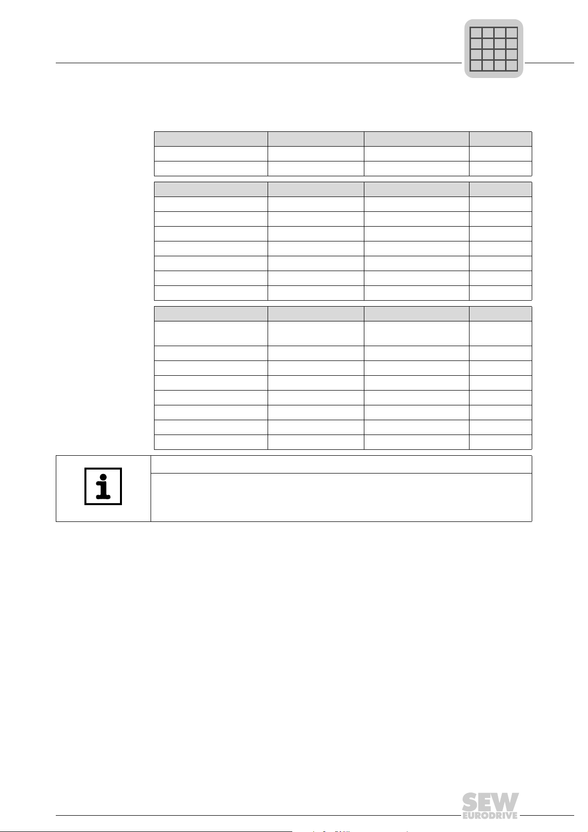
Overload protection for braking resistors BW:
Overload protection
Braking resistor type Design
specified
BW.. – – Required
1)
BW..-T
BW..-003 / BW..-005 Adequate – Permitted
1) Permitted mounting options: On horizontal or vertical surfaces with brackets at the bottom and perforated
sheets at top and bottom. Mounting not permitted: On vertical surfaces with brackets at the top, right or
left.
– One of the two options (internal temperature switch /
Internal temperature
switch (..T)
external bimetallic relay) is required.
External bimetallic
relay (F16)
36
Operating Instructions V3 – MOVITRAC® B
Page 37

4.11 Connecting brake rectifiers
DOØ2
GND
Cut-off in the
AC and DC circuits
Cut-off in the
AC and DC circuits
Cut-off in the
AC circuit
P
i
f
kVA
Hz
n
Phone: 800.894.0412 - Fax: 888.723.4773 - Web: www.clrwtr.com - Email: info@clrwtr.com
TIP
The connection of the brake rectifier requires a separate supply system cable; supply
from the motor voltage is not permitted!
Use only contactors of utilization category AC-3 for K11 and K12.
Switch off the brake on the DC and AC sides with:
• All hoist applications.
• Drives which require a rapid brake response time.
If the brake rectifier is installed in the control cabinet, route the connecting leads
between the brake rectifier and the brake separately from other power cables. Routing
together with other cables is only permitted if the other cables are shielded.
Wiring diagrams
Installation
Connecting brake rectifiers
4
Note the corresponding connection regulations for brakes without BG/BGE or BME.
Refer to the SEW publication "Drive Engineering – Practical Implemen tation: SEW Disk
Brakes".
Operating Instructions V3 – MOVITRAC® B
37
Page 38

4
X45
X46
1
23456HL ⊥
FSC11B
7
X44
S1 S2
OFF
ON
X45
X40
1
2345HL ⊥
FIO11B
X44
X46
X42
1
23456
FIO21B
7
X44
1
23
P
i
f
kVA
Hz
n
Phone: 800.894.0412 - Fax: 888.723.4773 - Web: www.clrwtr.com - Email: info@clrwtr.com
Installation
Installing FSC11B / FIO11B / FIO21B
4.12 Installing FSC11B / FIO11B / FIO21B
You can enhance the basic units using the FSC11B, FIO11B, and FIO21B modules.
Connection/unit FSC11B FIO11B FIO21B
RS-485 service interface X44 yes yes yes
RS-485 terminal connection X45 yes yes no
SBus connection X46 yes no yes
Analog input/output X40 no yes no
Binary inputs X42 no no yes
4.12.1 Mounting and installation on FSC11B / FIO11B / FIO21B
Always attach the option to the unit with the screw that is included in the delivery. For
size 0, mount the spacer bolt firs t. The bolt is already installed in sizes 1 and higher.
Fitting the screw secures the high-frequency EMC connection between the basic unit
and the option.
Function Termi-
nal
Service
X44 Via RJ10 plug
interface
RS-485
interface
System
bus
X45:H ST11: RS-485+ yes yes no
X45:L ST12: RS-485–
X45:
X46:1 SC11: SBus hi gh CAN bus to CAN
X46:2 SC12: SBus Low
X46:3 GND: Reference
X46:4 SC21: SBus High no
X46:5 SC22: SBus Low
X46:6 GND: Reference
Description Data FSC11B FIO11B FIO21B
connector
⊥ GND: Reference
potential
potential
potential
Only for service
purposes
Maximum cable
length 3 m (10 ft)
specification 2.0,
parts A and B
Max. 64 stations
yes yes yes
1)
yes
no yes
2)
38
Operating Instructions V3 – MOVITRAC® B
Page 39

Installation
P
i
f
kVA
Hz
n
Phone: 800.894.0412 - Fax: 888.723.4773 - Web: www.clrwtr.com - Email: info@clrwtr.com
Installing FSC11B / FIO11B / FIO21B
4
Function Termi-
nal
DC 24 V X46:7 24VIO: Auxiliary
Analog
input
Analog
output
Binary
inputs
1) Terminating resistor 120 Ω can be activated via DIP switch
2) Bus termination possible with enclosed 120 Ω resistor.
X40:1 AI2: Voltage input –10 – +10 V
X40:2 GND: Reference
X40:3 GND: Reference
X40:4 AOV1: Voltage
X40:5 AOI1: Current
X42:1 DI10 R
X42:2 DI11
X42:3 DI12
X42:4 DI13
X42:5 DI14
X42:6 DI15
X42:7 DI16
Description Data FSC11B FIO11B FIO21B
voltage / external
voltage supply
Ri > 40 kΩ
potential
potential
output
output
Resolution 10 bit
Sampling time
5ms
0 – +10 V
I
= 2 mA
max
0 (4) – 20 mA
Resolution 10 bit
Sampling time
5ms
Short-circuit proof,
protected against
external voltage
up to 30 V
= 3 kΩ, IE =
i
10mA, sampling
time 5 ms, PLCcompatible
yes no no
no yes yes
no yes yes
no no yes
The DC 24 V function of X46:7 is identical to X12:8 of the basic unit. All GND terminals
of the unit are connected to each other and to PE.
Cable specification • Use a 4-core twisted and shielded copper cable (data transmission cable with braided
Connecting the shield • Connect the shield to the electronics shield clamp on th e inverter or master controller and
copper shield). The cable must meet the following specifications:
– Cable cross-section 0.25 to 0.75 mm
– Cable resistance 120 Ω at 1 MHz
– Capacitance per unit length ≤ 40 pF/m at 1 kHz
Suitable cables include CAN bus or DeviceNet cables.
make sure it is connected over a wide area at both ends.
• There is no need for a ground connections between MOVITRAC
MOVITRAC® B and MOVITRAC® B with shielded cables. A 2-core cable is permitted in this
case.
• When connecting MOVIDRIVE
tion is eliminated between the reference potential DGND and ground in MOVIDRIVE® B.
®
B and MOVITRAC® B, be aware that the electrical isola-
2
(AWG 23 - AWG 18)
®
B and gateways, or
CAUTION
Potential displacement
Possible consequences include malfunctions that could lead to irreparable damage to
the unit.
• There must not be any potential displacement between the connected units. Take
appropriate measures to avoid potential displacement, such as connecting the un it
ground connectors using a separate cable.
Operating Instructions V3 – MOVITRAC® B
39
Page 40

4
X45
X46
1
23456HL⊥
FSC11B
MOVITRAC® B
S1
7
S2
X44
X45
X46
1
23456HL⊥
FSC11B
MOVITRAC® B
7
X44
MOVIDRIVE® B
SC11
DGND
ON OFF
S12
X12:
2
1
SC12
3
OFF
ON
S1 S2
OFF
ON
X45
X46
1
23456HL⊥
FSC11B
MOVITRAC® B
7
X44
S1 S2
OFF
ON
UFx
P
i
f
kVA
Hz
n
Phone: 800.894.0412 - Fax: 888.723.4773 - Web: www.clrwtr.com - Email: info@clrwtr.com
Installation
Installing FSC11B / FIO11B / FIO21B
4.12.2 Installing the system bus (SBus) to FSC11B
Max. 64 CAN bus stations can be addressed via system bus (SBus). The SBus supports
transmission technology compliant with ISO 11898.
S1 S2 SC11/SC12 SC21/SC22
off off CAN1 CAN1
on off CAN1 concluded –
X on Reserved
®
MOVITRAC
B system bus connection
MOVITRAC
®
B system bus connection with UFx
40
Operating Instructions V3 – MOVITRAC® B
Page 41

Installation
P
i
f
kVA
Hz
n
Phone: 800.894.0412 - Fax: 888.723.4773 - Web: www.clrwtr.com - Email: info@clrwtr.com
Installing FSC11B / FIO11B / FIO21B
4
MOVITRAC® B system bus connection with DFx/UOH11B gateways or DFx integrated
®
in MOVITRAC
UOH11B
DFP21B
RUN
BUS
FAULT
5
9
6
1
X30
01
0
2
1
2
2
2
3
2
4
2
5
2
6
2
AS
ADDRESS
H1
H2
X24
X26
23456
1
B
MOVITRAC® B
S1 S2
ON
OFF
X44
FSC11B
X46
X45
7
23456HL⊥
7
+ 24 V
GND
1
Cable length • T he permitted total cable length depends on the baud rate setting of the SBus (P884):
– 125 kBaud: 320 m (1050 ft)
– 250 kBaud: 160 m (525 ft)
– 500 kBaud: 80 m (260 ft)
– 1000 kBaud: 40 m (130 ft)
• You must use shielded cables.
TIP
Terminating resistor: Switch on the system bus terminating resistor (S1 = ON) at the
start and end of the system bus connection. Switch off the terminating resistor on the
units in between (S1 = OFF).
Certain units have a permanently integrated terminating resistor that cannot be
switched off. This is the case for UFx and DFx/UOH. These gateways form the end of
the physical line. Do not connect any external terminating resistors.
Operating Instructions V3 – MOVITRAC® B
41
Page 42

4
X45
X40
1
2345HL ⊥
RS-485+
RS-485–
GND
AI2
AOV1
GND
GND
AOC1
GND
–10 V
external
+10 V
external
P
i
f
kVA
Hz
n
Phone: 800.894.0412 - Fax: 888.723.4773 - Web: www.clrwtr.com - Email: info@clrwtr.com
Installation
Installing FSC11B / FIO11B / FIO21B
4.12.3 Installing RS-485 interface to FSC11B
The RS-485 interface can be used for connecting max. 32 MOVITRAC
MOVITRAC
MOVITRAC
®
®
units and a higher-level controller (PLC).
B RS-485 connection
®
units or 31
MOVITRAC® B
X44
FSC11B /
FIO11B
X46
X45
7
23456HL ⊥
1
Cable length • The permitted total cable length is 200 m.
• You must use shielded cables.
MOVITRAC® B
X44
FSC11B /
FIO11B
X46
X45
23456HL ⊥
1
TIP
Terminating resistor: Dynamic terminating resistors are installed. Do not connect any
external terminating resistors.
MOVIDRIVE® B
X13
9
DGND
10
ST11
11
ST12
7
4.12.4 Wiring the FIO11B analog module
Bipolar analog input
AI2
Unipolar analog
input AI2
RS-485+
RS-485–
GND
1
X40
AI2
GND
2345HL ⊥
GND
GND
X45
+10 V
external
or
X10:1
AOV1
AOC1
Current analog
output AOC1
X45
RS-485+
RL ≤ 750 Ω
X40
RS-485–
GND
AI2
2345HL ⊥
1
A
R
L
GND
GND
AOV1
AOC1
Voltage analog
output AOV1
X45
RS-485+
X40
RS-485–
GND
AI2
2345HL ⊥
1
GND
GND
V
AOV1
AOC1
42
Operating Instructions V3 – MOVITRAC® B
Page 43

Installing the MBG11A speed control module
A B
28 (1.1)
M4
68 (2.7)
56 (2.2)
60 (2.4)
88 (3.5)
A
A
A
A
B
B
X45
X46
1
23456HL ⊥
FSC11B
MOVITRAC® B
7
X44
1
234
MBG11A
S1 S2
OFF
ON
P
i
f
kVA
Hz
n
Phone: 800.894.0412 - Fax: 888.723.4773 - Web: www.clrwtr.com - Email: info@clrwtr.com
4.13 Installing the MBG11A speed control module
• A Mounting from the rear using 4 tapped holes.
• B Mounting from the front using 2 retaining holes
Installation
4
4.13.1 Connection
Operating Instructions V3 – MOVITRAC® B
43
Page 44

5
쓔
댷
쓔
Brake released*
}
n13 = n11 + n12
3-phase
REF1
24VIO
Enable/stop*
GND
PE
X2
X3
PE
3-phase
1-phase
Changeover
Reference potential analog signals
Fault reset
CW/stop
CCW/stop
Supply voltage
input/output
Reference potential binary signals
Reference potential
Ready
Reference potential
Relay contact/fault
NOC relay
NCC relay
Shield clamp
Factory setting
P
i
f
kVA
Hz
n
Phone: 800.894.0412 - Fax: 888.723.4773 - Web: www.clrwtr.com - Email: info@clrwtr.com
Startup
Brief description of the startup process
5Startup
5.1 Brief description of the startup process
You can directly connect the MOVITRAC® B frequency motor to a motor with the same
power rating. For example: A 1.5 kW (2.0 HP) motor can be connected directly to a
MC07B0015.
5.1.1 Procedure
1. Connect the motor to MOVITRAC
(terminal X2).
2. You have the option of connecting a
braking resistor (terminal X2/X3).
3. The following signal terminals must be
controlled with your control system:
• Enable DIØ3
• As required: CW/halt DIØ1 or CCW/
halt DIØ2
®
B
• Setpoint:
• Analog input X10 and/or
• DIØ4 = n11 = 150 rpm or/and
• DIØ5 = n12 = 750 rpm or/and
• DIØ4 + DIØ5 = n13 = 1500 rpm
• For brakemotors:
DOØ2 = Brake control using brake
rectifiers
4. You have the option of connecting the
following signal terminals:
• DIØØ = Fault reset
• DOØ1 = /Fault (designed as relay
contact)
• DOØ3 = Ready
5. Check the controller for the required
functionality.
6. Connect the frequency inverter to the
mains (X1).
5.1.2 Notes
Signal terminal functions and setpoint settings can be modified using the FBG11B keypad or a PC. A PC connection requires the FSC11B front option or one of the following
interface adapters: UWS21B / UWS11A / USB11A.
Operating Instructions V3 – MOVITRAC® B
44
Page 45

5.2 General startup instructions
P
i
f
kVA
Hz
n
Phone: 800.894.0412 - Fax: 888.723.4773 - Web: www.clrwtr.com - Email: info@clrwtr.com
DANGER
Uncovered power connections.
Severe or fatal injuries from electric shock.
• Install the touch guard according to the regulations.
• Never start the unit if the touch guard is not installed.
5.2.1 Prerequisite
The drive must be configured correctly to ensure that startup is successful.
®
MOVITRAC
SEW motor adapted to the correct power level (4-pole, 50 Hz) in V/f control mode. This
means you can take the adjuster motor from SEW-EURODRIVE into operation without
project planning.
B frequency inverters are factory set to be taken into operation with the
Startup
General startup instructions
5
5.2.2 Hoist applications
Risk of fatal injury if the hoist falls.
Severe or fatal injuries.
MOVITRAC
MOVITRAC
• Use monitoring systems or mechanical protection devices to ensure safety.
DANGER
®
B can be used in hoist applications.
®
B is not designed for use as a safety device.
Operating Instructions V3 – MOVITRAC® B
45
Page 46

5
P
i
f
kVA
Hz
n
Phone: 800.894.0412 - Fax: 888.723.4773 - Web: www.clrwtr.com - Email: info@clrwtr.com
Startup
Preliminary work and resources
5.3 Preliminary work and resources
• Check the installation.
DANGER
Risk of crushing if the motor starts up unintentionally.
Severe or fatal injuries.
• Ensure that the motor cannot start inadvertently, for example, by removing the
electronics terminal block X13.
• Additional safety precautions must be taken depending on the application, such as
monitoring systems or mechanical protection devices, to avoid injury to people and
damage to machinery.
5.3.1 Preliminary work and resources on the MOVITRAC
• Connect the power supply system and the mo to r.
• Connect the signal terminals.
®
B basic unit
• Switch on the power supply system.
5.3.2 Preliminary work and resources for MOVITRAC
• Connect the power supply system and the motor. Do not connect s ignal terminals
to prevent the inverter from receiving an enable!
• Switch on the power supply system.
• The display shows Stop.
• Program the signal terminals.
• Set the parameters (e.g. ramps).
• Check the set terminal assignment (P601 – P622).
• Switch off the power supply system.
• Connect the signal terminals.
• Switch on the power supply system.
TIP
The inverter automatically changes parameter values once you perform a startup.
®
B with keypad
46
Operating Instructions V3 – MOVITRAC® B
Page 47

5.4 Optional keypad FBG11B
out
Enter
RUN
STOP
RESET
STOP
RESET
RUN
P
i
f
kVA
Hz
n
Phone: 800.894.0412 - Fax: 888.723.4773 - Web: www.clrwtr.com - Email: info@clrwtr.com
Key arrangement and symbols on the keypad:
Startup
Optional keypad FBG11B
5
5.4.1 Keypad functions
The UP/DOWN and ENTER/OUT butto ns are used for navigating thr ough the menus.
Use the RUN and STOP/RESET buttons to control the drive. The speed control module
is used for setpoint specification.
The STOP/RESET button has priority over a terminal enable or an enable via the interface. If you stop a drive using the STOP/RESET key, you have to enable it again by
pressing the RUN key.
TIP
After switching off the power su pply, a drive that was previously stopped using the
STOP key will no longer be stopped!
The STOP/RESET key can be used for performing a reset after a fault has occu rred with
a programmed error response. The drive is then inhib ited and must be enabled by pressing the RUN key. You can deactivate the STOP function with parameter 760 using
FBG11B.
If you stop the drive with the STOP/RESET key, the display Stop is flashing. This signal
indicates you have to enable the drive using the "RUN" key.
After copying the parameter set in MOVITRAC
Use UP/DOWN to select symbols and change values.
Use ENTER/OUT to activate and deactivate the symbols or parameter menus
Use "RUN" to start the drive.
Use "STOP/RESET" to reset errors and stop the drive.
®
B, the unit is also stopped.
Operating Instructions V3 – MOVITRAC® B
47
Page 48

5
P
i
f
kVA
Hz
n
Phone: 800.894.0412 - Fax: 888.723.4773 - Web: www.clrwtr.com - Email: info@clrwtr.com
Startup
Basic operation of the FBG11B keypad
5.5 Basic operation of the FBG11B keypad
n
n
Par
xx
max
Level 1
Display
inverter status
speed
Display
ramp up
Display
ramp down
Selection
fixed setpoint menu
Display
maximum setpoint
Select
parameter menu
Level 2
Enter
out
Enter
out
Fixed setpoint menu
Enter
out
Enter
out
Parameter menu
out
Enter
Modify
ramp up [s]
Modify
ramp down [s]
Enter
out
Modify
maximum speed
[rpm]
out
Enter
Enter
Enter
Edit mode
Enter
Edit mode
Modify/accept
value
Modify/accept
value
Modify/accept
Enter
value
Modify/accept
value
Modify/accept
Enter
value
Select
motor startup
Select
data backup
Select FBG
speed ctr. module
Display
initial frequency
Display
output current
Enter
out
Motor statup menu
Enter
out
Data backup menu
Enter
out
FBG speed control module
48
Operating Instructions V3 – MOVITRAC® B
Page 49

5.5.1 Menu
P
i
f
kVA
Hz
n
Phone: 800.894.0412 - Fax: 888.723.4773 - Web: www.clrwtr.com - Email: info@clrwtr.com
The LED integrated in the symbol lights up when you select a symbol. If a symbol only
represents display values, the current display value appears immediately on the display.
5.5.2 Changing parameters
You can select the required parameter by selecting a symbol and pressing the ENTER
key.
Press the ENTER key again to edit the parameter value. You can alter the value when
the LED in the corresponding symbol flashes. When pressing th e ENTER key again, the
value becomes active and the LED does not flash any longer.
5.5.3 Status display
If the status is "Drive enabled", the display will show the calculated actual speed.
5.5.4 Fault display
Startup
Basic operation of the FBG11B keypad
5
In the event of a fault, the display changes and the fault code flashes in the dis pla y, fo r
example F-11 (refer to the fault list in the "Service / List of Faults" sect ion). This situation
will not occur during active startup.
5.5.5 Warnings
You may not alter any parameter in any operating mode. If you try to do so, the display
r-19 – r-32 will appear. The display shows a code depending on the action, e.g. r-28
(controller inhibit required). You find a list of warnings in the "Operation" section.
5.5.6 Parameter menu change short ↔ long
Using parameter P800, you can switch back and forth between short menu and long
menu. The parameter description and parameter list indicates which parameters are
accessible via short and long menu.
Operating Instructions V3 – MOVITRAC® B
49
Page 50

5
P
i
f
kVA
Hz
n
Phone: 800.894.0412 - Fax: 888.723.4773 - Web: www.clrwtr.com - Email: info@clrwtr.com
Startup
Manual operation with FBG11B speed control module
5.6 Manual operation with FBG11B speed control module
FBG11B speed control module of the keypad (local manual operation): LED
flashing
The only relevant parameters in "FBG speed control module" operating mode are:
• P122 Direction of rotation FBG manual operation
• "RUN" and "STOP/RESET" buttons
• Speed control module (potentiometer)
When the FBG speed control module is activated, the symbol flashes.
You limit the smallest speed with P301 Minimum speed and the largest speed with the
symbol.
n
max
After a fault, a reset can be performed using the "STOP/RESET" button via the terminal
or the interface. After a reset, the "manual speed control module" operating mode will
be active again. The drive remains stopped.
The Stop display flashes to indicate that you have to re-enable the drive by pressing
"RUN."
The parameter P760 Locking RUN/STOP keys does not have any effect in "manual
speed control module" operating mode.
Removing the FBG11B keypad will trigger a stop response.
50
Operating Instructions V3 – MOVITRAC® B
Page 51

5.7 External setpoint selection
P
i
f
kVA
Hz
n
Phone: 800.894.0412 - Fax: 888.723.4773 - Web: www.clrwtr.com - Email: info@clrwtr.com
External setpoint selection
Control via
–Terminals
– Serial interface
– Setpoint potentiometer connected to AI11/AI12
5.7.1 Set direction of rotation
You can specify the set direction of rotation:
• "CW/Stop and "CCW/S top" in P101 control signal source = termi nals or P101 control
signal source = 3 wire-control
• The polarity of the setpoint in the process data word in P101 Co ntrol signal source =
RS485 or SBus and P100 Setpoint source = RS485 or SBus
Startup
External setpoint selection
5
5.7.2 Setpoint speed
You can specify the setpoint speed using:
• Speed control module if P121 Addition FBG speed control module is set to ON
• P100 Setpoint source
– Fixed setpoints
– Fixed setpoints with analog input
– Process data word from SBus or RS-485
– Motor potentiometer
5.7.3 Direction of rotation enable with RS-485 or SBus
Unipolar setpoint sources:
Unipolar / fixed setpoint
Motor potentiometer / fixed setpoint
Fixed setpoint + AI1
Fixed setpoint* + AI1
Frequency setpoint input / fixed setpoint
The direction of rotation is set with the CW or CCW terminals.
Bipolar setpoint sources:
Bipolar / fixed setpoint
RS-485 / fixed setpoint
SBus 1 / Fixed setpoint
The direction of rotation is determined by the setpoint. Enable with terminal CW or CCW.
Operating Instructions V3 – MOVITRAC® B
51
Page 52

5
P
i
f
kVA
Hz
n
Phone: 800.894.0412 - Fax: 888.723.4773 - Web: www.clrwtr.com - Email: info@clrwtr.com
Startup
Startup using the FBG11B keypad
5.8 Startup using the FBG11B keypad
Level 1
out
Enter
Level 2
out
out
out
out
Enter
Enter
Enter
Enter
Level 3
Motor selection:
Select operating mode:
– SEW DRE motor
– SEW DRS motor
– Non-SEW motor
– SEW DT/DV motor
– U/f characteristic curve
– U/f + DC braking
– VFC
– VFC DC braking
– VFC Flying start function
– VFC hoist
Power in [KW]
HP = kW x 1.33
Motor voltage [V]
(
out
out
out
out
out
out
Enter
Enter
Enter
Enter
Enter
Enter
Rated motor frequency [Hz]
Rated motor speed
[rpm]
Rated motor current [A]
only available for startup
of non-SEW motors
(Motor = non-SEW)
cos phi
4Q operation
Number of motors for
multi-motor drives
)
52
Operating Instructions V3 – MOVITRAC® B
Page 53

5.8.1 Required data
P
i
f
kVA
Hz
n
Phone: 800.894.0412 - Fax: 888.723.4773 - Web: www.clrwtr.com - Email: info@clrwtr.com
The following data is required to ensure startup is successful:
• Motor type (SEW or non-SEW motor)
• Motor data
• Rated mains voltage
5.8.2 Activating startup
Requirements:
• Drive ”No enable”: Stop
If a smaller or a larger motor is connected (maximum diffe rence one size), then you have
to choose the value closest to the rated motor power.
Startup
Startup using the FBG11B keypad
– Rated voltage and rated frequency
– Additionally for non-SEW motors: Rated current, rated power, rated factor cos ϕ,
and rated speed.
5
5.8.3 V/f
5.8.4 VFC
The startup procedure is not complete until you have returned to the main menu level
by pressing the OUT button.
You can then perform startup only with motor parameter set 1.
NOTE
The SEW motor startup is designed for 4-pole motors. It may be useful to start
up 2-pole or 6-pole SEW motors as non-SEW motors.
The default setting for the operating mode is V/f. Use this operating mode if you have no
particular requirements and for applications where a high maximum speed is required.
Start up the inverter in VFC or VFC & DC brake operating mode for the following requirements:
• High torque
• Continuous duty at low frequencies
• Accurate slip compensation
• More dynamic behavior
For this purpose, you will have to choose the VFC or VFC & DC brake operating modes
from P-01 at startup.
Operating Instructions V3 – MOVITRAC® B
53
Page 54

5
P
i
f
kVA
Hz
n
Phone: 800.894.0412 - Fax: 888.723.4773 - Web: www.clrwtr.com - Email: info@clrwtr.com
5.8.5 Startup of multi-motor drive
5.8.6 Startup of group drives
Startup
Startup using the FBG11B keypad
Multi-motor drives are mechanically connected to each other (e.g. chain drive with
several motors). Observe the notes in the publication "Multi-Motor Drives".
Multi-motor drives are possible with installed identical SEW motors only.
• Set the multi parameter of the motor startup to th e number of connected motors.
Group drives are mechanically decoupled from each other (e.g. different conveyor
belts). In this operating mode, the inverter operates without slip compensation and with
a constant V/f ratio.
You can operate a group of asynchronous motors on one inverter in V/f characteristic
curve operating mode. Important:
• Select V/f operating mode
• Set the power of the largest motor
• Disable automatic adjustment P320/330
• Set boost P321/331 to zero
• Set IxR compensation P322/332 to zero
• Set slip compensation P324/334 to zero
• Set current limitation P303/313 to 1.5 times the total current of all motors
•Set I
Implement motor protection individually.
In this operating mode, the inverter operates without slip compensation and with a
constant V/f ratio.
NOTE
The parameter settings apply to all connected motors.
5.8.7 Startup with large mass moment of inertia, su ch as with pumps and fans
Slip compensation is designed for a ratio smaller than 10 of load moment of inertia to
motor moment of inertia. If the ratio is larger and the drive vibrates, then slip compensation must be reduced and even be set to 0 if necessary.
UL monitoring P345/346 to the total current of the connected motors.
rated
54
Operating Instructions V3 – MOVITRAC® B
Page 55

St artup with PC and MOVITOOLS® MotionStudio
P
i
f
kVA
Hz
n
Phone: 800.894.0412 - Fax: 888.723.4773 - Web: www.clrwtr.com - Email: info@clrwtr.com
5.9 Startup with PC and MOVITOOLS® MotionStudio
Start MOVITOOLS® MotionStudio in the Windows start menu:
Programs / SEW / MOVITOOLS MotionStudio 5.x / MotionStudio 5.x
®
Press the MOVITOOLS
tree.
MotionStudio [Scan] button to list all connected units in the unit
Startup
5
You can perform a startup by right-clicking on one of the units. You fin d additional information in the online help.
Operating Instructions V3 – MOVITRAC® B
55
Page 56

5
z
P
i
f
kVA
Hz
n
Phone: 800.894.0412 - Fax: 888.723.4773 - Web: www.clrwtr.com - Email: info@clrwtr.com
Startup
Startup of explosion-proof AC asynchronous motors of category 2 (94/9/EC)
5.10 Startup of explosion-proof AC asynchronous motors of category 2 (94/9/EC)
Explosion-proof AC motors from SEW-EURODRIVE that are taken into operation with
MOVITRAC
®
B must be approved for such operation according to the nameplate and
EC type examination certificate.
A certified safety function is used in conjunction with temperature sensors in the motor
to provide for a safe operation in potentially explosive areas. The current limitation
®
function in MOVITRAC
B prevents the activation of the safety device, i.e. the motor is
protected against impermissible overheating (→ following figure).
Current limitation
I
A
fAf
1
I
B
B
C
2
Permitted
continuous current range
f
C
Iü
f
base
f/H
1.5 IN (motor)
I
(motor)
N
Depending on
motor type
Iü
Use the MOVITOOLS
®
MotionStudio software for startup. During startup, parameters
P560 – P566 are automatically activated for SEW motors selected and approved for Exe operation.
After startup, P560 can only be activated if a motor approved for Ex-e operation has
been started up before.
After motor startup, current limitation I
is active. Current limitation I2 determines the
1
permanently permitted current (shaded area)
You can document the startup parameters and values with MOVITOOLS
MotionStudio. They are displayed in the "ATE X info rm at ion " wi nd ow .
®
56
Operating Instructions V3 – MOVITRAC® B
Page 57

5.11 Starting the motor
P
i
f
kVA
Hz
n
Phone: 800.894.0412 - Fax: 888.723.4773 - Web: www.clrwtr.com - Email: info@clrwtr.com
You have to exit manual operation before you can enable the motor via terminals.
5.11.1 Analog setpoint specification
The following table shows which sign als m ust be present on terminals X11:2 (AI1) and
X12:1 – X12:4 (DIØØ – DIØ3) when the "unipolar/fixed setpoint" setpoint is selected
(P100) in order to operate the drive with an analog setpoint entry.
Startup
Starting the motor
5
X11:2
Function
Controller
inhibit
Stop X 1 X X 0 0 0
Enable
and halt
Clock-
wise at 50
% n
max
Clockwise with
n
max
Counterclockwise
with 50 %
n
max
Counterclockwise
with n
max
1) No default setting
(AI11)
Analog
input n1
X0XXX00
X100100
5 V110100
10 V110100
5 V101100
10 V101100
X12:1
(DIØØ)
/Control-
ler
1)
inhibit
X12:2
(DIØ1)
CW/halt
X12:3
(DIØ2)
CCW/
halt
X12:4
(DIØ3)
Enable/
stop
X12:5
(DIØ4)
n11/n21
n12/n22
X12:6
(DIØ5)
0 = 0 signal
1 = 1 signal
X = Not relevant
Operating Instructions V3 – MOVITRAC® B
57
Page 58

5
1
1
1
1
1
0
0
0
0
0
0
10V
5V
0V
n
max
50 % n
max
-50 % n
max
-n
max
n
min
start-stop
n
n [rpm]
DIØØ input
/Controller inhibit
DIØ1 input
CW/Halt
DIØ2 input
CCW/Halt
DIØ3 input
Enable/
Stop
DBØØ output
/Brake
Analog
input n1 (AI11)
Speed
t11 up
t11 up
t11 up
t11 down
t11 down
t11 up
Stop ramp t13
P
i
f
kVA
Hz
n
Phone: 800.894.0412 - Fax: 888.723.4773 - Web: www.clrwtr.com - Email: info@clrwtr.com
Startup
Starting the motor
The following travel cycle shows by way of example how the motor is started with the
assignment of terminals X12:1 – X12:4 and analog setpoints. Binary output X10:3
(DBØØ "/Brake") is used for switching brake contactor K12.
TIP
The motor is not energized in the event of controller inhibit. A motor without brake will
coast to standstill.
Operating Instructions V3 – MOVITRAC® B
58
Page 59

5.11.2 Fixed setpoints
P
i
f
kVA
Hz
n
Phone: 800.894.0412 - Fax: 888.723.4773 - Web: www.clrwtr.com - Email: info@clrwtr.com
The following table shows which signals must be present on terminals X12:1 – X12:6
(DIØØ – DIØ5) when the "unipolar/fixed setpoint" setpoint is selected (P100) in order to
operate the drive with the fixed setpoints.
Startup
Starting the motor
5
X12:1
Function
Controller
inhibit
Stop 1 X X 0 X X
Enable and
stop
CW opera-
tion with n11
CW opera-
tion with n12
CW opera-
tion with n13
CCW opera-
tion with n11
0 = 0 signal
1 = 1 signal
X = Not relevant
(DIØØ)
/Control-
ler inhibit
0XX X XX
100 1 XX
110 1 10
110 1 01
110 1 11
101 1 10
X12:2
(DIØ1)
CW/halt
X12:3
(DIØ2)
CCW/halt
X12:4 (DIØ3)
Enable/stop
X12:5
(DIØ4)
n11/n21
X12:6
(DIØ5)
n12/n22
Operating Instructions V3 – MOVITRAC® B
59
Page 60

5
/
P
i
f
kVA
Hz
n
Phone: 800.894.0412 - Fax: 888.723.4773 - Web: www.clrwtr.com - Email: info@clrwtr.com
Startup
Starting the motor
The following travel cycle shows by way of example how the drive is started with the
assignment of terminals X12:1 – X12:6 and the internal fixed setpoints. Binary output
X10:3 (DBØØ "/Brake") is used for switching brake contactor K12.
n [rpm]
n13
n12
n11
-n11
-n12
-n13
1
0
1
0
1
0
1
0
1
0
1
0
1
0
t11 up
t11 up
t11 up
0
t11 down
t11 up
Stop ramp t13
DIØØ input
Controller inhibit
DIØ1 input
CW/Halt
DIØ2 input
CCW/Halt
DIØ3 input
Enable/
Stop
DIØ4 input
n11/n21
DIØ5 input
n12/n22
DBØØ output
/Brake
Speed
TIP
The motor is not energized in the event of controller inhibit. A motor without brake will
coast to standstill.
60
Operating Instructions V3 – MOVITRAC® B
Page 61

5.12 Parameter list
P
i
f
kVA
Hz
n
Phone: 800.894.0412 - Fax: 888.723.4773 - Web: www.clrwtr.com - Email: info@clrwtr.com
All parameters that can also be displayed and edited using the ke yp ad are ind i cated a s
follows in the "FBG" (keypad) column:
If a choice is offered, the factory setting is indicated in bold.
Selection in long menu
Selection in short or long menu
Selection using symbol on keypad and in long menu
Selection within FGB motor startup
Startup
Parameter list
5
No. FBG Index
dec.
0.. Display values (read only)
00. Process values
000 8318 Speed (signed) [rpm]
001 8501 User display for
002 8319 Frequency (signed) [Hz]
004 8321 Output current
005 8322 Active current
008 8325 DC link voltage [V]
009 8326 Output current [A]
01. Status displays
010 8310 Inverter status [Text]
011 8310 Operating state [Text]
012 8310 Error status [Text]
013 8310 Current parameter
014 8327 Heat sink
02. Analog setpoints
020 8331 Analog input AI1 [V]
021 8332 Analog input AI2
03. Binary inputs
030 8844 Binary input DI00 Error reset
031 8335 Binary input DI01 CW / halt (fixed assignment)
032 8336 Binary input DI02 CCW/halt
Name Range / factory setting Value
Display MOVITOOLS® MotionStudio
[Text]
DBG11B
]
[% I
(value)
(signed)
set
temperature
(optional)
N
[% IN]
Current parameter set
[°C]
[V]
after
startup
Operating Instructions V3 – MOVITRAC® B
61
Page 62

5
P
i
f
kVA
Hz
n
Phone: 800.894.0412 - Fax: 888.723.4773 - Web: www.clrwtr.com - Email: info@clrwtr.com
Startup
Parameter list
No. FBG Index
dec.
033 8337 Binary input DI03 Enable/stop
034 8338 Binary input DI04 n11/n21
035 8339 Binary input DI05 n12/n22
039 8334 Binary inputs DI00 –
04. Binary inputs option
040 Binary input DI10 No function
041 Binary input DI11 No function
042 Binary input DI12 No function
043 Binary input DI13 No function
044 Binary input DI14 No function
045 Binary input DI15 No function
046 Binary input DI16 No function
048 8348 Binary inputs DI10 –
05. Binary output s
051 8349 Binary output DO01 /fault
052 8349 Binary output DO02 Brake released
053 8349 Binary output DO03 Ready
059 8349 Bianry outputs DO01
07. Unit data
070 8301 Unit type [Text]
071 8361 Rated output current [A]
076 8300 Firmware of basic
077 – DBG firmware Only in DBG60B
08. Fault memory
080 – 084 8366 –
8370
09. Bus diagnostics
094 8455 PO 1 setpoint [hex]
095 8456 PO 2 setpoint [hex]
096 8457 PO 3 setpoint [hex]
097 8458 PI 1 actual value [hex]
Name Range / factory setting Value
Display MOVITOOLS® MotionStudio
Collective display of binary inputs
DI05
DI15
– DO03
unit
Fault t-0 – t-4 Fault
code
Collective display of binary inputs
Collective display of binary outputs
[Part number and version]
Background information for previous faults.
after
startup
62
Operating Instructions V3 – MOVITRAC® B
Page 63

Startup
P
i
f
kVA
Hz
n
Phone: 800.894.0412 - Fax: 888.723.4773 - Web: www.clrwtr.com - Email: info@clrwtr.com
Parameter list
5
No. FBG Index
dec.
098 8459 PI 2 actual value [hex]
099 8460 PI 3 actual value [hex]
1.. Setpoints / ramp generators (on FBG only parameter set 1)
10. Setpoint selection / frequency input
100 8461 Setpoint source 0
101 8462 Control signal source 0
102 8840 Frequency scaling 0.1 – 10 – 120.00 [kHz]
103 10247.15 FI1 reference 0
104 10247.10 Setpoint reference
105 10416.1 Wire breakage
106 10247.11 FI1 char. curve x1 0 – 100 %
107 10247.12 FI1 char. curve y1 –100 % – 0 – +100 %
108 10247.13 FI1 char. curve x2 0 – 100 %
109 10247.14 FI1 char. curve y2 –100 % – 0 – +100 %
11. Analog input 1 (0 – 10 V)
110 8463 AI1 scaling 0.1 – 1 – 10
112 8465 AI1 operating mode 1
113 8466 AI1 voltage offset –10 V – 0 – +10 V
116 1024 7.6 AI1 characteristic
117 1024 7.7 AI1 characteristic
118 1024 7.8 AI1 characteristic
119 1024 7.9 AI1 characteristic
Name Range / factory setting Value
Display MOVITOOLS® MotionStudio
Bipolar / fixed setpoint
Unipolar / fixed setpoint
RS-485 / fixed setpoint
Motor potentiometer/fixed setpoint
Fixed setpoint + AI1
Fixed setpoint* + AI1
MASTER SBus1
MASTER RS-485
SBus 1 / Fixed setpoint
Frequency setpoint input / Fixed setpoint
Bipolar AI2 / Fixed setpoint
Terminals
RS-485
SBus 1
3-wire control
n
max
n
reference
No response
Immediate stop/fault
Rapid stop/fault
Rapid stop/warning
10 V, reference maximum speed
0 – 20 mA, reference maximum speed
4 – 20 mA, reference maximum speed
0 – 10 V, n-reference
0 – 20 mA, n-reference
4 – 20 mA, n-reference
speed n
detection
curve x1
curve y1
curve x2
curve y2
1
2
4
6
7
8
9
10
11
14
1
3
4
1
0 – 3000 – 6000 rpm
ref
0
2
4
7
5
6
7
8
9
0 – 100 %
–100 % – 0 – +100 %
0 – 100 %
–100 % – 0 – +100 %
after
startup
Operating Instructions V3 – MOVITRAC® B
63
Page 64

5
P
i
f
kVA
Hz
n
Phone: 800.894.0412 - Fax: 888.723.4773 - Web: www.clrwtr.com - Email: info@clrwtr.com
Startup
Parameter list
No. FBG Index
dec.
12. Analog input AI2 / FBG speed control module (option)
120 8469 AI2 operating mode 0
121 8811 Addition FBG
122 8799 Direction of rotation
126 10247.1 AI2 characteristic
127 10247.2 AI2 characteristic
128 10247.3 AI2 char. curve x2 –100 % – 0 – +100 % (–10 V – 0 – +10 V)
129 10247.4 AI2 char. curve y2 –100 % – 0 – +100 % (–n
13. / 14. Speed ramps 1 / 2
130 / 140 8807 /
9264
131 / 141 8808 /
9265
134 / 144 8474 /
8482
135 / 145 8475 /
8483
136 / 146 8476 /
8484
139 / 149 8928 /
8929
15. Motor potentiometer function
150 8809 Ramp t3 up = down 0.2 – 20 – 50 [s]
152 8488 Save last setpoint Off
16. / 17. Fixed setpoints
160 / 170 8489 /
8492
161 / 171 8490 /
8493
162 / 172 8491 /
8494
163 / 173 8814 /
8817
164 / 174 8815 /
8818
165 / 175 8816 /
8819
Name Range / factory setting Value
Display MOVITOOLS® MotionStudio
No function
1
2
0
setpoint control
module
FBG manual operation
curve x1
curve y1
Ramp t11 / t21 up 0.1 – 2 – 2000 [s]
Ramp t11 / t21 down 0.1 – 2 – 2000 [s]
Ramp t12 / t22 0.1 – 10 – 2000 [s]
S pattern t12 / t22 0
Stop ramp t13 / t23 0.1 – 2 – 20 [s]
Ramp monitoring
1 / 2
Internal setpoint
n11 / n21
Internal setpoint
n12 / n22
Internal setpoint
n13 / n23
n11 / n21 PI
controller
n12 / n22 PI
controller
n13 / n23 PI
controller
1
2
0
1
2
–100 % – 0 – +100 % (–10 V – 0 – +10 V)
–100 % – 0 – +100 % (–n
1
2
3
0
1
On
0 – 150 – 5000 [rpm]
0 – 750 – 5000 [rpm]
0 – 1500 – 5000 [rpm]
0 – 3 – 100 [%]
0 – 15 – 100 [%]
0 – 30 – 100 [%]
0 – ±10 V + setpoint
0 – 10 V current limit
Off
On
On (without fixed setpoint)
Unipolar CW
Unipolar CCW
Bipolar CW and CCW
– 0 – +n
max
– 0 – +n
max
Off
Weak
Medium
Strong
YES
NO
Off
On
max
max
/ 0 – I
/ 0 – I
max
max
after
startup
)
)
64
Operating Instructions V3 – MOVITRAC® B
Page 65

Startup
P
i
f
kVA
Hz
n
Phone: 800.894.0412 - Fax: 888.723.4773 - Web: www.clrwtr.com - Email: info@clrwtr.com
Parameter list
5
No. FBG Index
dec.
2.. Controller parameter
25. PI controller
250 8800 PI controller 0
251 8801 P-gain 0 – 1 – 64
252 8802 I-component 0 – 1 – 2000 [s]
253 8465 PI actual value mode 1
254 8463 PI actual value
255 8812 PI actual value offset 0.0 – 100.0 [%]
3.. Motor parameters (on FBG only parameter set 1)
30. / 31. Limits 1 / 2
300 / 310 8515 /
8519
301 / 311 8516 /
8520
302 / 312 8517 /
8521
303 / 313 8518 /
8522
32. / 33. Motor adjustment 1 / 2
320 / 330 8523 /
8528
321 / 331 8524 /
8529
322 / 332 8525 /
8530
323 / 333 8526 /
8531
324 / 334 8527 /
8532
34.
345 / 346 9114 /
9115
4.. Reference signals
40. Speed reference signals
400 8539 Speed reference
401 8540 Hysteresis 0 – 100 – +500 [rpm]
402 8541 Delay time 0 – 1 – 9 [s]
403 8542 Signal = "1" when 0
Name Range / factory setting Value
Display MOVITOOLS® MotionStudio
Off
1
2
5
6
7
8
9
scaling
Start/stop speed 1 / 2 0 – 150 [rpm]
Minimum speed 1 / 2 0 – 15 – 5500 [rpm]
Maximum speed
1 / 2
Current limit 1 / 2 0 – 150 [% I
Automatic
adjustment 1 / 2
Boost 1 / 2 0 – 100 [%]
IxR compensation
1/2
Premagnetization
time 1 / 2
Slip compensation
1/2
IN UL monitoring
IN UL monitoring
1 / 2
value
0.1 – 1.0 – 10.0
0 – 1500 – 5500 [rpm]
Off
On
0 – 100 [%]
0 – 2 [s]
0 – 500 [rpm]
0.1 – 500 A
0 – 750 – 5000 [rpm]
1
Normal
Inverted
10 V, reference maximum speed
0 – 20 mA, reference maximum speed
4 – 20 mA, reference maximum speed
0 – 10 V, n-reference
0 – 20 mA, n-reference
4 – 20 mA, n-reference
]
N
Off
On
n < n
ref
n > n
ref
after
startup
Operating Instructions V3 – MOVITRAC® B
65
Page 66

5
P
i
f
kVA
Hz
n
Phone: 800.894.0412 - Fax: 888.723.4773 - Web: www.clrwtr.com - Email: info@clrwtr.com
Startup
Parameter list
No. FBG Index
dec.
43. Current reference signal
430 8550 Current reference
431 8551 Hysteresis 0 – 5 – 30 % I
432 8552 Delay time 0 – 1 – 9 s
433 8553 Signal = "1" when 0
44. Imax signal
440 8554 Hysteresis 0 – 5 – 50 % I
441 8555 Delay time 0 – 1 – 9 s
442 8556 Signal = "1" when 0
45. PI controller reference signal
450 8813 PI actual value refer-
451 8796 Signal = "1" if 0
5.. Control functions (on FBG only parameter set 1)
50. Speed monitoring 1 / 2
500 / 502 8557 /
8559
501 / 503 8558 /
8560
54. Gear unit/motor monitoring
540 9284 Response to drive
541 9285 Response to drive
542 9286 Response to oil
543 9287 Response to oil
544 9288 Oil aging / over-
545 9289 Oil aging / ready
549 9290 Response to brake
Name Range / factory setting Value
Display MOVITOOLS® MotionStudio
0 – 100 – 150 % I
value
1
1
0.0 – 100.0 %
ence
1
Speed monitoring
1 / 2
Delay time 1 / 2 0 – 1 – 10 [s]
vibration / warning
vibration / fault
aging / fault
aging/warning
temperature
signal
wear
0
3
N
N
I < I
ref
I > I
ref
N
I < I
max
I > I
max
PI Actual value < PI ref
PI Actual value > PI ref
Off
Motor/regenerative
Factory setting: Display error
Factory setting: Rapid stop/warning
Factory setting: Display error
Factory setting: Display error
Factory setting: Display error
Factory setting: Display error
Factory setting: Display error
after
startup
66
Operating Instructions V3 – MOVITRAC® B
Page 67

Startup
P
i
f
kVA
Hz
n
Phone: 800.894.0412 - Fax: 888.723.4773 - Web: www.clrwtr.com - Email: info@clrwtr.com
Parameter list
5
No. FBG Index
dec.
56. Current limit Ex-e motor:
560 9293 Current limit Ex-e
561 9294 Frequency A 0 – 5 – 60 Hz
562 9295 Current limit A 0 – 50 – 150 %
563 9296 Frequency B 0 – 10 – 104 Hz
564 9297 Current limit B 0 – 80 – 200 %
565 9298 Frequency C 0 – 25 – 104 Hz
566 9299 Current limit C 0 – 100 – 200 %
6.. Terminal assignment
60. Binary inputs
601 8336 Binary input DI02
602 8337 Binary input DI03
603 8338 Binary input DI04
604 8339 Binary input DI05
608 8844 Binary input DI00
61. Binary inputs
610 8340 Binary input DI10
611 8341 Binary input DI11
612 8342 Binary input DI12
613 8343 Binary input DI13
614 8344 Binary input DI14
615 8345 Binary input DI15
616 8346 Binary input DI16
Name Range / factory setting Value
Display MOVITOOLS® MotionStudio
ON / OFF
motor
0: No function
assignment
assignment
assignment
assignment
assignment
option
assignment
assignment
assignment
assignment
assignment
assignment
assignment
1: Enable / stop (factory setting DI03)
2: CW/halt
3: CCW / halt (factory setting DI02)
4: n11/n21 (factory setting DI04)
5: n12/n22 (factory setting DI05)
n13 = n11 + n12
6: Fixed setpoint switchover
7: Parameter set switchover
8: Ramp switchover
9: Motor potentiometer up
10: Motor potentiometer down
1 1 : /External fault
12: Fault reset (factory setting DI00)
19: Slave free running
20: Setpoint acceptance active
26: TF signal (only with DI05)
27: Vibration/warning
28: Vibration/fault
29: Brake wear
30: Controller inhibit
33: Oil aging/warning
34: Oil aging/fault
35: Oil aging / overtemperature
36: Oil aging/ready
after
startup
Operating Instructions V3 – MOVITRAC® B
67
Page 68

5
P
i
f
kVA
Hz
n
Phone: 800.894.0412 - Fax: 888.723.4773 - Web: www.clrwtr.com - Email: info@clrwtr.com
Startup
Parameter list
No. FBG Index
dec.
62. Binary output s
620 8350 Binary output DO01
621 8351 Binary output DO02
622 8916 Binary output DO03
64. Analog outputs AO1 (optional)
640 8568 AO1 analog output 0
641 10248.5 AO1 reference 0
642 8570 AO1 Operating
646 10246.1 AO1 char. curve x1 –100 % – 0 – +100 %
647 10246.2 AO1 char. curve y1 0 – 100 %
648 10246.3 AO1 char. curve x2 –100 % – 0 – +100 %
649 10246.4 AO1 char. curve y2 0 – 100 %
7.. Control functions (on FBG only parameter set 1)
70. Operating modes 1 / 2
700 / 701 8574 /
8575
Name Range / factory setting Value
Display MOVITOOLS® MotionStudio
0: No function
assignment
assignment
assignment
mode
Operating mode 1 / 2 0
1
2
3
4
5
6
7
11
12
1
2
0
2
3
4
2
3
4
21
22
1: /Fault (factory setting DO01)
2: Ready (factory setting DO03)
3: Output stage ON
4: Rotating field ON
5: Brake released (factory setting DO02 / not
with DO03)
8: Parameter set
9: Speed reference message
11: Setpoint-actual value comparison signal
12: Current reference signal
13: Imax signal
21: IPOS output
22: /IPOS fault
23: PI controller actual value reference
24: Ex-e current limit active (in preparation)
27: Safe stop
30: Ixt warning
31: Ixt fault
No function
Ramp generator input
Setpoint speed
Actual speed
Actual frequency
Output current
Active current
Unit utilization
Actual speed (signed)
Actual frequency (signed)
3000 rpm, 100 Hz, 150 %
n
max
n
set reference
No function
0–20 mA
4–20 mA
0–10 V
VFC
VFC & Hoist
VFC & DC braking
VFC & flying start function
V/f characteristic curve
V/f & DC braking
after
startup
68
Operating Instructions V3 – MOVITRAC® B
Page 69

Startup
P
i
f
kVA
Hz
n
Phone: 800.894.0412 - Fax: 888.723.4773 - Web: www.clrwtr.com - Email: info@clrwtr.com
Parameter list
5
No. FBG Index
dec.
71. Standstill current 1 / 2
710 / 711 8576 /
8577
72. Setpoint stop function 1 / 2
720 / 723 8578 /
8581
721 / 724 8579 /
8582
722 / 725 8580 /
8583
73. Brake function 1 / 2
731 / 734 8749 /
8750
732 / 735 8585 /
8587
74. Speed skip function
740 / 742 8588 /
8590
741 / 743 8589 /
8591
75. Master/slave function
750 8592 Slave setpoint
751 8593 Scaling slave
76. Manual operation
760 8798 Lock RUN/STOP
77. Energy-saving function
770 8925 Energy-saving
8.. Unit functions (on FBG only parameter set 1)
80. Setup
800 – Quick menu long
801 – DBG language
802 8594 Factory setting No
803 8595 Parameter lock Off
804 8596 Reset statistics data No action
805 – Rated mains voltage 50 – 500 V
806 – Copy DBG →
Name Range / factory setting Value
Display MOVITOOLS® MotionStudio
Standstill current
1 / 2
Setpoint stop
function 1 / 2
Stop setpoint 1 / 2 0 – 30 – 500 [rpm]
Start offset 1 / 2 0 – 30 – 500 [rpm]
Brake release time
1 / 2
Brake application
time 1 / 2
Skip window center
1 / 2
Skip width 1 / 2 0 – 300 rpm
setpoint
keys
function
MOVITRAC
®
B
0 – 50 % I
Off
On
0 – 2 [s]
0 – 2 [s]
0 – 1500 – 5000 rpm
Off
On
Off
On
short
Hours
ALL
NEMA
On
Mot
Off
On
Off
On
Off
On
0 / No
1 / Standard
2 / Delivery status
4 / NEMA delivery status
Off
On
Fault memory
Yes
No
after
startup
Operating Instructions V3 – MOVITRAC® B
69
Page 70

5
P
i
f
kVA
Hz
n
Phone: 800.894.0412 - Fax: 888.723.4773 - Web: www.clrwtr.com - Email: info@clrwtr.com
Startup
Parameter list
No. FBG Index
dec.
807 – Copy MOVITRAC®
808 8660 24 V output voltage Off
809 10204.1 IPOS enable Off
81. Serial communication
810 8597 RS-485 address 0 – 99
811 8598 RS-485 group
812 8599 RS-485 timeout
82. Brake operation 1 / 2
820 / 821 8607 /
8608
83. Error responses
830 8609 Response terminal
833 8612 Response to
836 8615 Response to SBus
84. Reset behavior
840 8617 Manual reset Yes
841 8618 Auto reset Off
842 8619 Restart time 1 – 3 – 30 s
85. Scaling actual speed value
850 8747 Scaling factor
851 8748 Scaling factor
852 8772 /
8773
853 9312 Scaled speed FBG 0
86. Modulation 1 / 2
860 / 861 8620 /
8621
862 / 863 8751 /
8752
Name Range / factory setting Value
Display MOVITOOLS® MotionStudio
Yes
B → DBG
100 – 199
address
interval
4-quadrant operation
1 / 2
"external fault"
RS-485 timeout
timeout
numerator
denominator
User-defined unit Text
PWM frequency 1 / 2 4
PWM fix 1 / 2 On
0 – 650 [s]
Off
On
2
4
7
1 – 65535 ( can be set with SHELL only)
1 – 65535 ( can be set with SHELL only)
1
8
12
16
Off
No
On
On
Off
On
Immediate stop / fault
Rapid stop / fault (830)
Rapid stop / warning (833 / 836)
No
On
Speed
Scaled speed
4 kHz
8 kHz
12 kHz
16 kHz
On
Off
after
startup
70
Operating Instructions V3 – MOVITRAC® B
Page 71

Startup
P
i
f
kVA
Hz
n
Phone: 800.894.0412 - Fax: 888.723.4773 - Web: www.clrwtr.com - Email: info@clrwtr.com
Parameter list
5
No. FBG Index
dec.
87. Process data parameter setting
870 8304 Setpoint description
871 8305 Setpoint description
872 8306 Setpoint description
873 8307 Actual value
874 8308 Actual value
875 8309 Actual value
876 8622 Enable PO data No
88. Serial communication SBus
880 8937 SBus protocol 0 / MoviLink
881 8600 SBus address 0 – 63
882 8601 SBus group address 0 – 63
883 8602 SBus timeout inter-
884 8603 SBus baud rate 125
886 8989 CANopen address 1 – 2 – 127
Name Range / factory setting Value
Display MOVITOOLS® MotionStudio
No function (factory setting P872)
PO1
PO2
PO3
description PI1
description PI2
description PI3
1 / CANopen
0 – 650 [s]
val
250
500
1000
Setpoint speed (factory setting P871)
Max. speed
Ramp
Control word 1 (factory setting P870)
Control word 2
Setpoint speed [%]
IPOS PO data
PI controller setpoint [%]
No function
Actual speed (factory setting P874)
Output current (factory setting P875)
Active current
Status word 1 (factory setting P873)
Actual speed [%]
IPOS PI-DATA
PI controller actual value [%]
Yes
125 kBd
250 kBaud
500 kBaud
1 MBaud
after
startup
Operating Instructions V3 – MOVITRAC® B
71
Page 72

6
P
i
f
kVA
Hz
n
Phone: 800.894.0412 - Fax: 888.723.4773 - Web: www.clrwtr.com - Email: info@clrwtr.com
Operation
Data backup
6 Operation
6.1 Data backup
6.1.1 Data backup using FBG1 1 B
Use the FBG11B keypad to download parameter data from the MOVITRAC
keypad or copy from the keypad to MOVITRAC
After copying the parameters, check them for accuracy.
Data backup using FBG11B
®
®
B.
B to the
Level 1
Select
data backup
out
Level 2
Enter
After copying data, the MOVITRAC
®
B is inhibited. The inhibited status is indicated by
Level 3
Enter
Parameter data from
FBG11B MOVITRAC
Enter
Parameter data from
MOVITRAC
®
B FBG11B
®
Enter
B
Enter
Start
loading
Start
saving
a flashing STOP in the status display. The status LED also slowly flashes yellow.
You can revoke the inhibit by taking one of the following measures:
• Pressing the RUN button on the FBG11B.
• Switching the mains off, waiting 10 seconds, and switching the mains back on.
6.1.2 Data backup using DBG60B
®
Copy the parameter set from MOVITRAC
B to the DBG60B keypad. You have the
following options:
• In the context menu, select the "COPY TO DBG" menu item. Confirm your selection
by pressing OK. The parameter set is copied from MOVITRAC
• In the context menu, select the "PARAMETER MODE" menu item. Select parameter
P807 "MCB → DBG". The parameter set is copied from MOVITRAC
6.1.3 Data backup using UBP11A
®
Copy the parameter set from MOVITRAC
B to the UBP11A parameter module. To do
so, press the button at the lower end of the mod ule. You need a po inted object for this
purpose.
72
Operating Instructions V3 – MOVITRAC® B
®
B to DBG60B.
®
B to DBG60B.
Page 73

6.1.4 Data backup using MOVITOOL S® MotionStudio
[1]
[2]
P
i
f
kVA
Hz
n
Phone: 800.894.0412 - Fax: 888.723.4773 - Web: www.clrwtr.com - Email: info@clrwtr.com
®
When you use MOVITOOLS
frequency inverter, you must re-enable the inverter as follows:
• Select the unit in the network.
• Open the context menu with a right mouse clock
• Select menu [RUN/STOP via software keypad] [1]
• Select [RUN] in the software keypad [2]
MotionStudio to transfer data to the MOVITRAC® B
Operation
Return codes (r-19 – r-38)
6
6.2 Return codes (r-19 – r-38)
Return codes MOVITRAC® B:
No. Designation Meaning
19 Parameter lock activated Parameters cannot be changed
20 Factory setting in progress Parameters cannot be changed
23 Option card missing The option card required for the function is missing.
27 Option card missing The option card required for the function is missing.
28 Controller inhibit required Controller inhibit required
29 Invalid value for parameter. • Invalid value for parameter.
32 Enable You cannot perform this function in ENABLED status
34 Error during execution • Error while saving in FBG11B.
38 FBG11B incorrect data set Stored data set does not match the unit
• FGB manual operation selection invalid as PC is
in active manual operation.
• Startup not performed with FBG. Perform FGB
startup with MotionStudio or select a new motor.
Operating Instructions V3 – MOVITRAC® B
73
Page 74

6
1
0
DO03
DO02
DO01
1
0
DI15
DI14
DI13
DI16
DI12
DI11
DI10
1
0
DI04
DI03
DI02
DI05
DI01
DI00
P
i
f
kVA
Hz
n
Phone: 800.894.0412 - Fax: 888.723.4773 - Web: www.clrwtr.com - Email: info@clrwtr.com
6.3 Status displays
6.3.1 FBG11B keypad
Operation
Status displays
If the status is "Drive enabled", the display will show the calculated actual speed.
Status Display
Drive "Controller inhibit" oFF
Drive "No enable" StoP
Drive "Enable" 8888 (actual speed)
Factory setting SEt (Set)
Standstill current dc
24 V operation 24U
Status of binary
inputs / outputs
Parameter P039 (binary inputs of basic unit) , parameter P059 (bina ry outputs of option),
and parameter P059 (binary outputs) are available as display parameters in the
parameter menu. The status is displayed as binary. Every binary input or output has two
segments vertically on top of one another of the 7-segment display assigned to it. The
upper segment lights up when the binary input or output is set, and the lower segment
lights up when the binary input or outp ut is not set. The two 7-segment displays on the
right indicate whether P039 (di = binary inputs basic unit), P048 (dI = binary inputs
option), or P059 (do = binary outputs) are output.
If no FIO21B with binary inputs is available, the display will show di - - -.
74
Operating Instructions V3 – MOVITRAC® B
Page 75

6.3.2 LED flash codes
P
i
f
kVA
Hz
n
Phone: 800.894.0412 - Fax: 888.723.4773 - Web: www.clrwtr.com - Email: info@clrwtr.com
The LED on the front of the unit signals the following states:
Operation
Unit status codes
6
Status Display (optional with
FBG)
"ENABLE" Speed Constant green light
"ENABLE" at current limit Speed flashes Rapid green flashing
"CURRENT AT STAND-
STILL"
Timeout Faults 43 / 46 / 47 Flashing green/yellow
"NO ENABLE" Stop Constant yellow light
"FACTORY SETTING" SEt Rapid yellow flashing
"CONTROL.INHIBIT" oFF Rapid yellow flashing
"24 V operation" Flashing 24U Slow yellow flashing
"SAFE STOP" Flashing U Slow yellow flashing
FGB manual operation
active or inverter stopped
using "stop" button.
Copy Fault 97 Flashing red/yellow
System fault Faults 10 / 17 ... 24 / 25 / 32
Overvoltage / phase failure Faults 4 / 6 / 7 Slow red flashing
Overload Faults 1 / 3 / 11 / 44 / 84 Rapid red flashing
Monitoring Faults 8 / 26 / 34 / 81 / 82 2 x red flashing
Motor protection Faults 31 / 84 3 x red flashing
dc Slow green flashing
FGB manual operation
symbol or "stop" is flashing
/ 37 / 38 / 45 / 77 / 80 / 94
LED flash code status of basic
unit
Yellow on long, off briefly
Constant red light
Incorrect interpretation of display U = "Safe stop" active.
Severe or fatal injuries.
The display U = "Safe stop" is not safety-related and must not be used as a safety
function.
6.4 Unit status codes
Use status word 1 to determine the unit status code.
Code Meaning
0x0 Not ready
0x1 Controller inhibit
0x2 No enable
0x3 Standstill current active, no enable
0x4 Enable
0x8 Factory setting is active
WARNING
Operating Instructions V3 – MOVITRAC® B
75
Page 76

7
P
i
f
kVA
Hz
n
Phone: 800.894.0412 - Fax: 888.723.4773 - Web: www.clrwtr.com - Email: info@clrwtr.com
Service / List of Faults
Unit information
7 Service / List of Faults
7.1 Unit information
7.1.1 Fault memory
The inverter stores the error message in fault memory P080. The inve rter does not save
a new fault until the error message has been acknowledged. The local operating panel
shows the most recent fault. Whenever double faults occur, the value stored in P080
does not correspond to the value displayed on the operating panel. This is an example
of what happens with F-07 DC link overvoltage followed by F34 Ramp timeout.
The inverter stores the following information when a malfunction occurs:
• Error occurred
• Status of the binary inputs / binary outputs
• Operating status of the inverter
• Inverter status
• Heat sink temperature
• Speed
• Output current
• Active current
• Unit utilization
• DC link voltage
7.1.2 Switch-off responses
There are 3 switch-off responses depending on the fault:
Immediate
switch-off
Stop This fa ult res pon s e c au se s a st op at the se t stop ramp (P136 / P146). This fault stop is
This fault response causes immediate locking of the output stage with simultaneous
control of the brake output so that an existing brake is applied. The "fault message" is
set and the "ready message" is revoked.
This status can only be exited by an explicit fault reset.
subject to time monitoring. If the dr ive does not reach the start / stop speed within a
specified time period, the unit goes to the fault state, the ou tput stage is inhibited and an
existing brake is applied. The fault message "F34 Ramp timeout" is generated. The
original fault message is overwritten. If the drive reaches the start/stop speed, the unit
goes to the fault state, the brake is applied and the output stage is inhibited. The "fault
message" is set and the "ready message" is revoked.
This status can only be exited by an explicit fault reset.
Timeout (warning) If the inverter is controlled via a communication interface (RS-485 or SBus) and the
mains power was switched off and back on again, the enable remains ineffective until
the inverter once again receives valid data via the interface, which is monitored with a
timeout.
76
Operating Instructions V3 – MOVITRAC® B
Page 77

Service / List of Faults
P
i
f
kVA
Hz
n
Phone: 800.894.0412 - Fax: 888.723.4773 - Web: www.clrwtr.com - Email: info@clrwtr.com
7.1.3 Reset
Reset basic unit An error message can be acknowledged by:
• Reset via input terminals with an appropriately assigned binary input (DIØØ,
DIØ2...DIØ5). Factory setting for DIØØ is fault reset.
Reset keypad An error message can be acknowledged by:
• Manual reset on the keypad (STOP/RESET key).
The "STOP/RESET" key has priority over a terminal enable or an enable via the interface.
The STOP/RESET key can be used for performing a reset after a fault has occu rred with
a programmed error response. A reset inhibits the drive. To enable the drive, press the
RUN key.
Interface reset An error message can be acknowledged by:
®
• Manual reset in MOVITOOLS
status window of the reset button.
MotionStudio / P840 Manual reset = Yes, or in the
Unit information
7
Operating Instructions V3 – MOVITRAC® B
77
Page 78

7
P
i
f
kVA
Hz
n
Phone: 800.894.0412 - Fax: 888.723.4773 - Web: www.clrwtr.com - Email: info@clrwtr.com
Service / List of Faults
List of faults (F-00 – F-113)
7.2 List of faults (F-00 – F-113)
No. Designation Response Possible cause Measure
00 No error
01 Overcurrent Immediate switch-
off with inhibit
03 Ground fault Immediate switch-
off with inhibit
04 Brake chopper Immediate switch-
off with inhibit
06 Mains phase
failure
07 DC link
overvoltage
08 Speed
monitoring
09 Startup Immediate switch-
Immediate switchoff with inhibit (only
with 3-phase
inverter)
Immediate switchoff with inhibit
Immediate switchoff with inhibit
off with inhibit
• Short circuit on output • Rectify the short circuit
• Switching on output • Switching with inhibited output
• Motor too large • Connect a smaller motor
• Faulty output stage • Consult SEW Service if the error
• Ground fault in motor • Replace motor
• Ground fault in inverter • Replace MOVITRAC
• Ground fault in the motor supply
lead
• Overcurrent (see F-01) • See F-01
• Too much regenerative power • Extend deceleration ramps
• Braking resistor circuit interrupted
• Short circuit in the braking
resistor circuit
• Brake resistor resistance too
high
• Brake chopper defective • Replace MOVITRAC
• Ground fault • Eliminate ground fault
• Phase failure • Check the power supply cable
• Supply voltage too low • Check the supply voltage
• DC link voltage too high • Extend deceleration ramps
• Ground fault • Eliminate ground fault
Current controller works at the set
limit due to:
• Mechanical overload • Reduce load
• Phase failure in supply system • Check mains phases
• Phase failure in motor • Check motor cable and motor
• Maximum speed for VFC operating modes exceeded
• Inverter not started yet • Start up the inverter
• Unknown motor selected • Select another motor
stage only
cannot be reset
®
B
• Eliminate ground fault
• Check supply cable to the
braking resistor
• Rectify the short circuit
• Check technical data of braking
resistor
®
B
• Check supply cable to the
braking resistor
• Check technical data of braking
resistor
• Check current limitation
• Extend deceleration ramps
• Increase P501 deceleration time
• Reduce maximum speed
setting
1)
78
Operating Instructions V3 – MOVITRAC® B
Page 79

Service / List of Faults
P
i
f
kVA
Hz
n
Phone: 800.894.0412 - Fax: 888.723.4773 - Web: www.clrwtr.com - Email: info@clrwtr.com
List of faults (F-00 – F-113)
No. Designation Response Possible cause Measure
10 IPOS-ILLOP Stop with inhibit
with IPOS only
11 Over-
temperature
System
17
malfunction
...
24
25 EEPROM Stop with inhibit • Fault while accessing EEPROM • Activate factory settings,
26 External
terminal
31 TF/TH sensor
tripped
32 IPOS index
overflow
34 Ramp timeout Immediate switch-
35 Ex-e protection
operating mode
Stop with inhibit • Thermal overload of inverter • Reduce load and/or ensure
Immediate switchoff with inhibit
Programmable • Read in external fault signal via
Stop with inhibit • Motor too hot, TF sensor has
Stop with inhibit • Programming principles violated
off with inhibit
Programmable • Wrong operating mode selected • Permitted modes:
• Wrong command during
program execution
• Incorrect conditions during
program execution.
• Function does not exist / is not
implemented in the inverter
• Inverter electronics is faulty,
possibly due to EMC influence
programmable input
tripped
• TF sensor of motor not connected or connected incorrectly
• Connection of MOVITRAC
and TF on motor interrupted
leading to internal stack overflow
• Set ramp time exceeded • Exten d the ramp time
• If you remove the inhibit and the
drive exceeds the stop ramp
time t13 by a certain time, the
inverter will signal F34.
• Non-permitted parameter set • Use parameter set 1 only
• No Ex-e motor taken into
operation
• Incorrectly parameterized
frequency points
• Current limits not set correctly • Current limit A < current limit B
®
• Check the program
• Check program run
• Use another function
adequate cooling
• If a braking resistor is integrated
in the heat sink: Install braking
resistor externally
• Check grounding and shielding
and improve, if necessary.
• Contact SEW Service for advice
if this fault reoccurs.
perform reset and reset
parameters.
• Contact SEW Service for advice
if this fault reoccurs.
• Eliminate respective cause;
reprogram terminal if necessary.
• Let motor cool off and reset
error
• Check connections / links
between MOVITRAC® B and TF
B
• Check user program and correct
it
• Extend the stop ramp time
• V/f, VFC, VFC hoist
• Non-permitted modes:
• Flying start function
• DC braking
• Group operation
• Take Ex-e motor into operation
• Frequency A < frequency B
• Frequency B < frequency C
• Current limit B < current limit C
7
Operating Instructions V3 – MOVITRAC® B
79
Page 80

7
P
i
f
kVA
Hz
n
Phone: 800.894.0412 - Fax: 888.723.4773 - Web: www.clrwtr.com - Email: info@clrwtr.com
Service / List of Faults
List of faults (F-00 – F-113)
No. Designation Response Possible cause Measure
36 Option missing Immediate switch-
37 System
watchdog
38 System
software
43 RS-485 timeout Stop without
44 Unit utilization Immediate switch-
45 Initialization Immediate switch-
47 System bus 1
timeout
77 IPOS control
word
80 RAM test Immediate discon-
81 Start condition Immediate switch-
82 Open output Immediate switch-
off with inhibit
Immediate switchoff with inhibit
Immediate switchoff with inhibit
2)
inhibit
off with inhibit
off with inhibit
Stop without inhibit • F ault during communication via
Stop with inhibit • System malfunction • Contact SEW Service for advice
nection
off with inhibit
off with inhibit
• Type of option card not allowed • Use correct option card
• Setpoint source, control signal
source or operating mode not
permitted for this option card
• Required option missing • Check the following parameters:
• Fault in system software
sequence
• System malfunction • Check grounding and shielding
• Connection between inverter
and PC interrupted
• Unit utilization (Ixt value) exceeded
• Error during initialization • Contact SEW Service for advice
system bus
Internal unit fault, RAM defective. Contact SEW Service
Only in "VFC hoist" operating
mode:
The motor could not be supplied
with the correct amount of current
during the pre-magnetizing time:
• Rated motor power too small in
relation to rated inverter power
• Motor cable cross section too
small
Only in "VFC hoist" operating
mode:
• 2 or all output phases interrupted
• Rated motor power too small in
relation to rated inverter power
• Set correct setpoint source
• Set correct control signal source
• Set the correct operating mode
• Check parameters P120 and
P121
• P121 for FBG11B
• P120 and P642 for FIO12B
• Check grounding and shielding
and improve, if necessary.
• Contact SEW Service for advice
if this fault reoccurs.
and improve, if necessary.
• Contact SEW Service for advice
if this fault reoccurs.
• Check connection between
inverter and PC
• Decrease power output
• Extend ramps
• If mentioned points not possible:
Use a larger inverter
• Check system bus connection
• Check connection between
inverter and motor
• Check startup data and perform
new startup, if necessary
• Check cross section of motor
cable and increase if necessary
• Check connection between
inverter and motor
• Check startup data and perform
new startup, if necessary
80
Operating Instructions V3 – MOVITRAC® B
Page 81

Service / List of Faults
P
i
f
kVA
Hz
n
Phone: 800.894.0412 - Fax: 888.723.4773 - Web: www.clrwtr.com - Email: info@clrwtr.com
SEW electronics service
No. Designation Response Possible cause Measure
84 Motor
protection
94 EEPROM
checksum
97 Copy error Immediate switch -
98 CRC error flash Immediate
100 Vibration /
warning
101 Oscillation fault Rapid stop Vibration sensor signals fault SEW-EURODRIVE recommends
102 Oil aging /
warning
103 Oil aging/fault Display error Oil aging sensor signals fault SEW-EURODRIVE recommends
104 Oil aging / over-
temperature
105 Oil aging /
ready signal
106 Brake wear Display error Brake lining worn down Replace brake lining (→ "Motors"
110 "Ex-e
protection" fault
113 Analog input
open circuit
116 "Timeout
MOVI-PLC"
fault
1) Speed monitoring is set by changing parameters 500 / 502 and 501 / 503. The sagging of hoists cannot be avoided safely when
monitoring is deactivated or the delay time is set too long.
2) No reset required, e rror message disappears after communication is reestablished
Stop with inhibit • Motor utilization too high • Check P345/346 IN UL
Immediate switchoff with inhibit
off with inhibit
disconnection
Display error Vibration sensor warning (→
Display error Oil aging sensor warns Schedule oil change
Display error Oil aging sensor signals over-
Display error Oil aging sensor is not ready for
Stop with inhibit Duration of operation below 5 Hz
programmable AI1 analog input open circuit • Check the wiring
Rapid stop/warning MOVI-PLC
• Defective EEPROM • Contact SEW Service
• Parameter module is removed
during copying process
• Switching off/on during copying
process
Internal unit fault Flash memory
defective
"DUV10A" operating instructions)
temperature
operation
exceeded
®
out
communication time-
monitoring
• Reduce load
• Extend ramps
• Longer pause times
Prior to confirming the error:
• Load factory setting or complete
data set from parameter module
Send unit in for repair
Determine cause of vibrations.
Continue operation until F101
occurs.
that you remedy the cause of the
vibrations immediately
that you change the gear unit oil
immediately.
• Let oil cool down
• Check if the gear unit cools
properly
• Check voltage supply of oil
aging sensor
• Check and, if necessary,
replace the oil aging sensor
operating instructions)
• Check project planning
• Shorten duration of operation
below 5 Hz
• Check startup
• Check wiring
7
7.3 SEW electronics service
7.3.1 Hotline
Call the Drive Service Hotline to talk to an SEW-EURODRIVE service specialist on 365
days a year, 24 hours a day.
Simply dial the prefix 01805 and then enter the key combination SEWHELP. Or simply
dial 018057394357.
Operating Instructions V3 – MOVITRAC® B
81
Page 82

7
P
i
f
kVA
Hz
n
Phone: 800.894.0412 - Fax: 888.723.4773 - Web: www.clrwtr.com - Email: info@clrwtr.com
7.3.2 Sending in for repair
Service / List of Faults
Extended storage
Please contact the SEW Electronics Service if you cannot rectify a fault.
Please always specify the unit status code number when you contact the SEW
electronics service so that our service personnel can assist you more effectively.
Provide the following information when sending the unit in for repair:
Serial number (→ nameplate)
Unit designation
Short description of application (application, control via terminals or serial)
Connected motor (motor voltage, star or delta connection)
Nature of the fault
Accompanying circumstances
Your own presumptions as to what has happened
Unusual events preceding the problem
7.4 Extended storage
If the unit is being stored for a long time, connect it to the mains voltage for at least
5 minutes every 2 years. Otherwise, the unit's service life may be reduced.
Procedure when maintenance has been neglected:
Electrolytic capacitors are used in the inverters. They are su bject to aging effects wh en
deenergized. This effect can damage the electrolytic capacitors if the unit is connected
using the rated voltage after a longer period of storage.
If you have not performed maintenance regularly, SEW-EURODRIVE recommends that
you increase the line voltage slowly up to the maximum voltage. This can be done, for
example, by using a variable transformer for which the output voltage has been set
according to the following overview. SEW-EURODRIVE recommends that you increase
the voltage from 0 V to the first stage after a few seconds.
SEW-EURODRIVE recommends the following stages:
AC 400/500 V units:
• Stage 1: AC 350 V for 15 minutes
• Stage 2: AC 420 V for 15 minutes
• Stage 3: AC 500 V for 1 hour
AC 230 V units:
• Stage 1: AC 170 V for 15 minutes
• Stage 2: AC 200 V for 15 minutes
• Stage 3: AC 240 V for 1 hour
After you have completed the regeneration process, the unit can be used immediately
or stored again for an extended period with maintenance.
82
Operating Instructions V3 – MOVITRAC® B
Page 83

CE marking, UL approval and C-Tick
U
L
U
S
C
P
i
f
kVA
Hz
n
Phone: 800.894.0412 - Fax: 888.723.4773 - Web: www.clrwtr.com - Email: info@clrwtr.com
8 Technical Data
8.1 CE marking, UL approval and C-Tick
8.1.1 CE-marking
®
MOVITRAC
Directive 73/23/EEC.
MOVITRAC
in machines and systems. They comply with the EMC product standard EN 61800-3
Variable-speed electrical drives. Provided the installation instructions are complied with,
they satisfy the relevant requirements for the CE marking for the entire machine/system
in which they are installed, on the basis of the EMC Directive 89/336/EEC. For detailed
information on EMC compliant installation, refer to the publication "Electromagnetic
Compatibility in Drive Engineering" from SEW-EURODRIVE.
Compliance with limit classes C2 and C1 has been tested on a specified test setup.
SEW-EURODRIVE can provide detailed information on request.
The CE mark on the nameplate indicates conformity with the low voltage directive 73/
23/EEC. We can provide a declaration of conformity on request.
B frequency inverters comply with the regulations of the Low Voltage
®
B frequency inverters are designed for use as components for insta llation
Technical Data
8
8.1.2 UL approval / CSA / GOST-R certificate / C-Tick
UL and cUL approval (USA) has been granted for the following MOVITRAC
• 230 V / single-phase
• 230 V / 3-phase
• 400/500 V / 3-phase (0.25 – 45 kW / 0.34 – 60 HP)
cUL approval has been applied for the other units. cUL is equivalent to CSA approval.
The GOST-R certificate (Russia) was grante d for th e MO VIT RAC
C-Tick approval was applied for the entire MOVITRAC
conformity with ACMA (Australian Communications and Media Authority) standards.
®
B units:
®
B unit series.
®
B series. C-Tick certifies
Operating Instructions V3 – MOVITRAC® B
83
Page 84

8
P
i
f
kVA
Hz
n
Phone: 800.894.0412 - Fax: 888.723.4773 - Web: www.clrwtr.com - Email: info@clrwtr.com
Technical Data
General technical data
8.2 General technical data
The following technical data applies to all MOVITRAC® B frequency inverters independent of size and power.
MOVITRAC® B All sizes
Interference immunity Meets EN 61800-3
Interference emission with
EMC-compliant installation
Leakage current > 3.5 mA
Ambient temperature ϑ
(up to 60 °C with current
reduction)
Derating ambient temperature
(current reduction)
Climate class EN 60721-3-3, class 3K3
Storage temperature
Transport temperature
Type of cooling Self-cooled: 230 V: ≤ 0.75 kW (1.0 HP)
Degree of protection
EN 60529 (NEMA1)
Duty cycle Continuous duty
Overvoltage category III according to IEC 60664-1 (VDE 0110-1)
Mains voltage tolerance EN 50160: ±10 %
Pollution class 2 according to IEC 60664-1 (VDE 0110-1)
A
According to limit value class
• Sizes 0 to 2: C2 without further measures
• Sizes 0 to 5: C1 with corresponding filters / folding ferrites
C1/C2 to EN 61800-3
• 230 V, 0.25 – 2.2 kW (0.34 – 3.0 HP) / 400/500 V, 0.25 – 4.0 kW (0.34 – 5.4 HP)
With overload capacity (max. 150% for 60 s):
I
= 100 % IN / f
D
Without overload capacity:
= 100 % IN / f
I
D
ID = 100 % IN / f
ID = 125 % IN / f
• 3 × 230 V, 3.7 – 30 kW (5.0 – 40 HP) / 400/500 V, 5.5 – 75 kW (7.4 – 100 HP)
With overload capacity (max. 150% for 60 s):
= 100 % IN / f
I
D
Without overload capacity:
ID = 100 % IN / f
= 100 % IN / f
I
D
ID = 125 % IN / f
• Mounting plate with "cold plate" < 70°C (+158 °F)
2.5 % I
3 % I
–25 °C – +75 °C (–13 °F – 167 °F)
–25 °C – +75 °C (–13 °F – 167 °F)
400/500 V: ≤ 1.1 kW (1.5 HP)
Forced cooling: 230 V: ≥ 1.1 kW (1.5 HP)
(temperature controlled fan, 400/500 V: ≥ 1.5 kW (3.0 HP)
Response threshold 45 °C (113 °F))
Sizes 0 to 3: IP20
Sizes 4 – 5 power connections:
•IP00
• With the supplied Plexiglas cover mounted an d shrinking tube mounted (not
per K at 40 °C – 50 °C (104 °F – 122 °F)
N
per K at 50 °C – 60 °C (122 °F – 140 °F)
N
supplied) IP10
PWM
PWM
PWM
PWM
PWM
PWM
PWM
PWM
1)
= 4 kHz: –10 °C – +40 °C (14 °F – 104 °F)
= 4 kHz: –10 °C – +50 °C (14 °F – 122 °F)
= 8 kHz: –10 °C – +40 °C (14 °F – 104 °F)
= 4 kHz: –10 °C – +40 °C (14 °F – 104 °F)
= 4 kHz: 0 °C – + 40 °C (32 °F – 104 °F)
= 4 kHz: 0 °C – + 50 °C (32 °F – 122 °F)
= 8 kHz: 0 °C – + 40 °C (32 °F – 104 °F)
= 4 kHz: 0 °C – + 40 °C (32 °F – 104 °F)
84
Operating Instructions V3 – MOVITRAC® B
Page 85

Technical Data
P
i
f
kVA
Hz
n
Phone: 800.894.0412 - Fax: 888.723.4773 - Web: www.clrwtr.com - Email: info@clrwtr.com
General technical data
MOVITRAC® B All sizes
Installation altitude Up to h ≤ 1000 m (3281 ft) without restrictions.
The following restrictions apply at h ≥ 1000 m (3281 ft):
• from 1000 m (3281 ft) to max. 4000 m (13120 ft):
–I
reduction by 1 % per 100 m (328 ft)
N
• from 2000 m (6562 ft) to max. 4000 m (13120 ft):
– AC 230 V units: Reduction of the rated mains voltage V
100 m (328 ft)
– AC 500 V units: Reduction of the rated mains voltage V
100 m (328 ft)
Over 2000 m (6562 ft) only overvoltage class 2, external measures are required for
overvoltage class 3. Overvoltage classes according to DIN VDE 0110-1.
Dimensioning According to DIN ISO 276-v
Size 0:
Restrictions for continuous
duty with 125 % I
1) Electrical installation in compliance with applicable regulations is necessary for maintaining the EMC limit value class. Comply with the
installation notes.
N
• Maximum ambient temperature ϑA: 40 °C (104 °F)
• Maximum rated mains voltage V
• No DIN rail mounting / submounting resistor
• At 1 × 230 V: Provide ND line choke
mains
: 400 V
by AC 3 V per
mains
by AC 6 V per
mains
8
Operating Instructions V3 – MOVITRAC® B
85
Page 86

8
P
i
f
kVA
Hz
n
Phone: 800.894.0412 - Fax: 888.723.4773 - Web: www.clrwtr.com - Email: info@clrwtr.com
Technical Data
MOVITRAC® B electronics data
8.3 MOVITRAC® B electronics data
Function Terminal Designa-
tion
Setpoint input
ential input)
Binary inputs X12:1
Supply voltage for TF X12:7 V OTF Special characteristics for TF according to
Auxiliary voltage
output/external voltage
supply
Reference terminal X12:9 GND Reference potential for binary and analog signals,
Binary outputs X13:1
Relay output X13:5
1)
(differ-
2)
X10:1
X10:2
X10:3
X10:4
X12:2
X12:3
X12:4
X12:5
X12.6
X12:8 24VIO Auxiliary supply output: V = DC 24 V, current
X13:2
X13:3
X13:4
X13:6
X13:7
REF1
AI11 (+)
AI12 (–)
GND
DI00
DI01
DI02
DI03
DI04
DI05TF
GND
DO02
DO03
GND
DO01-C
DO01-NO
DO01-NC
Default Data
+10 V, R
0 – +10 V (R
0 – 20 mA / 4 – 20 mA (R
10 bit resolution, sampling time 1 ms
GND = Reference potential for binary and analog
signals, PE potential
Fault reset
CW/halt
CCW/halt
Enable/stop
n11/n21
n12/n22
Brake released
Ready
R
= 3 kΩ, IE = 10 mA, sampling time 5 ms, PLC
i
compatible
Signal level according to EN 61131-2 type 1 or 3:
•+11 – +30 V → 1 / contact closed
• –3 – +5 V → 0 / contact open
• X12:2 / DI01 with fixed assignment CW/halt
• X12:5 / DI04 can be used as frequency input
• X12:6 / DI05 can be used as TF input
DIN EN 60947-8 / trigger value 3 kΩ
carrying capacity I
External voltage supply:
V = DC 24 V –15% / +20% according to
EN 61131-2
See the Project planning/external DC 24 V
voltage supply section.
PE potential
PLC compatible, response time 5 ms,
I
max
short-circuit proof, protected against external
voltage up to 30 V
GND = Reference potential for binary and analog
signals, PE potential
Shared relay contact
NO contact
NC contact
Load capacity: V
= 3 kΩ
Lmin
> 200 kΩ)
i
max
DO02 = 150 mA, I
= 30 V, I
max
= 250 Ω),
i
= 50 mA
DO03 = 50 mA,
max
max
= 800 mA
86
Operating Instructions V3 – MOVITRAC® B
Page 87

Technical Data
P
i
f
kVA
Hz
n
Phone: 800.894.0412 - Fax: 888.723.4773 - Web: www.clrwtr.com - Email: info@clrwtr.com
MOVITRAC® B electronics data
8
Function Terminal Designa-
tion
Safety contact X17:1 GND: Reference potential for X17:2
X17:2 VO24: U
to supply other units.
X17:3 SOV24: Reference potential for DC+24 V "safe stop" input (safety contact)
X17:4 SVI24: DC+24 V "safe stop" input (safety contact)
Permitted cable cross
section
Power consumption
X17:4
Input capacitance
X17:4
Time for restart
Time to inhibit output
stage
Signal level DC +19.2 V – +30 V = "1" = contact closed
Terminal response
times
Max. cable crosssection
Cable stripping length X10 / X12 / X13: 5 mm
Tightening torque X10 / X12 / X13: 0.25 Nm
1) If the setpoint input is not used, it should be set to GND. Otherwise a measured input voltage of –1 V ... +1 V is set.
2) The MC07B...-S0 unit type must always be supplied with external voltage.
Binary input and output terminals are updated every 5 ms
2
1.5 mm
1.0 mm
FSC11B / FIO11B / FIO21B: 7 mm
FSC11B / FIO11B / FIO21B: 0.22 – 0.25 Nm
(AWG15) without conductor end sleeves
2
(AWG17) with conductor end sleeves
Default Data
= DC 24 V, only to supply X17:4 of the same unit; it cannot be used
OUT
2
One core per terminal: 0.08 – 1.5 mm
Two cores per terminal: 0.25 – 1.0 mm
Size 0: 3 W
Size 1: 5 W
Size 2, 2S: 6 W
Size 3: 7.5 W
Size 4: 8 W
Size 5: 10 W
Size 0: 27 µF
Sizes 1 to 5: 270 µF
t
= 200 ms
A
t
= 200 ms
S
DC –30 V – +5 V = "0" = contact open
(AWG28 – 16)
2
(AWG23 – 17)
8.3.1 DC 24 V power demand for 24 V backup mode
Size Basic unit power
demand
0 MC07B..-00 5 W
0 MC07B..-S0 12 W
1, 2S, 2 17 W
3 23 W
4, 5 25 W
1) FBG11B, FSC11B (UWS11A/USB11A) included. Take account of the additional load of the binary inputs
with 2.4 W per 100 mA.
2) Fieldbus options are: DFP21B, DFD11B, DFE11B, ...
3) These options must always be supplied externally.
1)
DBG60B FIO11B Fieldbus option
1 W 2 W 3 W 4.5 W
Operating Instructions V3 – MOVITRAC® B
2)3)
DHP11B
3)
87
Page 88

8
0XS0XS0XS
0S0S0S
0L0L0L
2S2S2S
22
44
33
400 / 500 V 230 V
0XS0XS0XS
0S0S0S
0L0L0L
11
22
44
33
55
P
i
f
kVA
Hz
n
Technical Data
Technical data of MOVITRAC® B
8.4 Technical data of MOVITRAC® B
8.4.1 Overview of MOVITRAC® B
88
Power supply connection 400 / 500 V / 3-phase
Size 0XS 0S 0L 2S 2 3 4 5
Power
[kW / HP]
Power supply connection 230 V / 1-phase
Size 0XS 0S 0L
Power
[kW / HP]
Power supply connection 230 V / 3-phase
Size 0XS 0S 0L 1 2 3 4
Power
[kW / HP]
0.25 / 0.34
0.37 / 0.50
0.25 / 0.34
0.37 / 0.50
0.55 / 0.74
0.75 / 1.0
1.1 / 1.5
1.5 / 2.0
0.25 / 0.34
0.37 / 0.50
0.55 / 0.74
0.75 / 1.0
2.2 / 3.0
3.0 / 4.0
4.0 / 5.4
1.1 / 1.5
1.5 / 2.0
2.2 / 3.0
5.5 / 7.4
7.5 / 10
0.55 / 0.74
0.75 / 1.0
3.7 / 5.0
15 / 20
11 / 15
22 / 30
30 / 40
5.5 / 7.4
7.5 / 10
Operating Instructions V3 – MOVITRAC® B
37 / 50
45 / 60
1.1 / 1.5
1.5 / 2.0
2.2 / 3.0
11 / 15
15 / 20
55 / 74
75 / 100
22 / 30
30 / 40
Page 89

Technical Data
P
i
f
kVA
Hz
n
Phone: 800.894.0412 - Fax: 888.723.4773 - Web: www.clrwtr.com - Email: info@clrwtr.com
Technical data of MOVITRAC® B
8.4.2 AC 400 / 500 V / 3-phase / size 0XS / 0.25 / 0.37 kW / 0.34 / 0.50 HP
8
6 (0.2)
220 (8.66)
196 (7.72)
6 (0.2)
MOVITRAC® MC07B (3-phase power supply) 0003-5A3-4-00 0004-5A3-4-00
Part number 828 515 2 828 516 0
1)
INPUT
Rated mains voltage V
Rated mains frequency f
Rated mains current, 100 % operation
Rated mains current, 125 % operation
OUTPUT
Output voltage V
Recommended motor power 100 % operation
Recommended motor power 125 % operation
Rated output current 100 % operation
Rated output current 125 % operation
Apparent output power 100 % operation
Apparent output power 125 % operation
Minimum permitted braking resistance value
(4 quadrant operation)
GENERAL INFORMA TION
Power loss 100 % operation
Power loss 125 % operation
Current limitation 150 % IN for at least 60 seconds
Terminal cross section / tightening torque Terminals 4 mm
Dimensions W × H × D 54.5 × 185 × 163.5 mm / 2.15 × 7.28 × 6.437 in
Mass m 1.3 kg / 2.9 lb
1) The mains and output curren ts must be reduced by 20 % from the nominal values for V
54.5 (2.15)
mains
mains
I
mains
I
mains 125
O
P
Mot
P
Mot 125
I
N
I
N 125
S
N
S
N 125
R
BW_min
P
V
P
V 125
49.5 (1.95)
285 (11.2)
163.5 (6.437)
149 (5.87)
159.5 (6.280)
3 × AC 380 – 500 V
50 / 60 Hz ± 5 %
AC 0.9 A
AC 1.1 A
3 × 0 – U
0.25 kW / 0.34 HP
0.37 kW / 0.50 HP
AC 1.0 A
AC 1.3 A
0.7 kVA
0.9 kVA
30 W
35 W
2
/ AWG12 / 0.5 Nm / 4 lb in
= 3 × AC 500 V.
mains
185 (7.28)
AC 1.4 A
AC 1.8 A
mains
0.37 kW / 0.50 HP
0.55 kW / 0.74 HP
AC 1.6 A
AC 2.0 A
1.1 kVA
1.4 kVA
68 Ω
35 W
40 W
Operating Instructions V3 – MOVITRAC® B
89
Page 90

8
80 (3.1)
163.5 (6.437)
185 (7.28)
196 (7.72)
285 (11.2)
70 (2.8)
159.5 (6.280)
149 (5.87)
6 (0.2)
6 (0.2)
220 (8.66)
P
i
f
kVA
Hz
n
Phone: 800.894.0412 - Fax: 888.723.4773 - Web: www.clrwtr.com - Email: info@clrwtr.com
Technical Data
Technical data of MOVITRAC® B
8.4.3 AC 400 / 500 V / 3-phase / size 0S / 0.55 / 0.75 / 1.1 / 1.5 kW / 0.74 / 1.0 / 1.5 / 2.0 HP
MOVITRAC® MC07B (3-phase power supply) 0005-5A3-4-x00008-5A3-4-x00011-5A3-4-x00015-5A3-4-
x0
Part number, standard unit (-00)
Part number "Safe stop" (-S0)
2)
INPUT
1)
Rated mains voltage V
Rated mains frequency f
Rated mains current, 100 % operation
Rated mains current, 125 % operation
mains
mains
I
mains
I
mains 125
828 517 9
828 995 6
AC 1.8 A
AC 2.3 A
828 518 7
828 996 4
3 × AC 380 – 500 V
50 / 60 Hz ± 5 %
AC 2.2 A
AC 2.6 A
828 519 5
828 997 2
AC 2.8 A
AC 3.5 A
828 520 9
828 998 0
AC 3.6 A
AC 4.5 A
OUTPUT
Output voltage V
Recommended motor power 100 %
operation
Recommended motor power 125 %
O
P
Mot
P
Mot 125
0.55 kW /
0.74 HP
0.75 kW /
1.0 HP
3 × 0 – V
0.75 kW /
1.0 HP
1.1 kW /
1.5 HP
mains
1.1 kW /
1.5 HP
1.5 kW /
2.0 HP
1.5 kW /
2.0 HP
2.2 kW /
3.0 HP
operation
Rated output current 100 % operation
Rated output current 125 % operation
Apparent output power 100 % operation
Apparent output power 125 % operation
Minimum permitted braking resist ance value
(4 quadrant operation)
GENERAL INFORMA TION
Power loss 100 % operation
Power loss 125 % operation
I
N
I
N 125
S
N
S
N 125
R
BW_min
P
V
P
V 125
AC 2.0 A
AC 2.5 A
1.4 kVA
1.7 kVA
40 W
45 W
AC 2.4 A
AC 3.0 A
1.7 kVA
2.1 kVA
45 W
50 W
68 Ω
AC 3.1 A
AC 3.9 A
2.1 kVA
2.7 kVA
50 W
60 W
AC 4.0 A
AC 5.0 A
2.8 kVA
3.5 kVA
60 W
75 W
Current limitation 150 % IN for at least 60 seconds
2
Terminal cross section / tightening torque Termina ls 4 mm
/ AWG12 / 0.5 Nm / 4 lb in
Dimensions W × H × D 80 × 185 × 163.5 mm / 3.1 × 7.28 × 6.437 in
Mass m 1.5 kg / 3.3 lb
1) The unit type MC07B...-S0 must always be supplied by an external DC 24 V power supply unit.
2) The mains and output curren ts must be reduced by 20 % from the nominal values for V
= 3 × AC 500 V.
mains
90
Operating Instructions V3 – MOVITRAC® B
Page 91

Technical Data
P
i
f
kVA
Hz
n
Phone: 800.894.0412 - Fax: 888.723.4773 - Web: www.clrwtr.com - Email: info@clrwtr.com
Technical data of MOVITRAC® B
8.4.4 AC 400 / 500 V / 3-phase / size 0L / 2.2 / 3.0 / 4.0 kW / 3.0 / 4.0 / 5.4 HP
8
163.5 (6.437)
149 (5.87)
273.5 (10.77)
159.5 (6.280)
6 (0.2)
284.5 (11.20)
308.5 (12.15)
6 (0.2)
80 (3.1)
70 (2.8)
373.5 (14.70)
MOVITRAC® MC07B (3-phase power supply) 0022-5A3-4-x0 0030-5A3-4-x0 0040-5A3-4-x0
Part number, standard unit (-00)
Part number "Safe stop" (-S0)
2)
INPUT
1)
Rated mains voltage V
Rated mains frequency f
Rated mains current, 100 % operation
Rated mains current, 125 % operation
mains
mains
I
mains
I
mains 125
828 521 7
828 999 9
AC 5.0 A
AC 6.2 A
828 522 5
829 000 8
3 × AC 380 – 500 V
50 / 60 Hz ± 5 %
AC 6.3 A
AC 7.9 A
828 523 3
829 001 6
AC 8.6 A
AC 10.7 A
OUTPUT
Output voltage V
Recommended motor power 100 % operation
Recommended motor power 125 % operation
Rated output current 100 % operation
Rated output current 125 % operation
Apparent output power 100 % operation
Apparent output power 125 % operation
Minimum permitted braking resistance value
(4 quadrant operation)
O
P
Mot
P
Mot 125
I
N
I
N 125
S
N
S
N 125
R
BW_min
2.2 kW / 3.0 HP
3.0 kW / 4.0 HP
AC 5.5 A
AC 6.9 A
3.8 kVA
4.8 kVA
3 × 0 – V
mains
3.0 kW / 4.0 HP
4.0 kW / 5.4 HP
AC 7.0 A
AC 8.8 A
4.8 kVA
6.1 kVA
68 Ω
4.0 kW / 5.4 HP
5.5 kW / 7.4 HP
AC 9.5 A
AC 11.9 A
6.6 kVA
8.2 kVA
GENERAL INFORMA TION
Power loss 100 % operation
Power loss 125 % operation
P
P
V
V 125
80 W
95 W
95 W
120 W
125 W
180 W
Current limitation 150 % IN for at least 60 seconds
2
Terminal cross section / tightening torque Terminals 4 mm
/ AWG12 / 0.5 Nm / 4 lb in
Dimensions W × H × D 80 × 273.5 × 163.5 mm / 3.1 × 10.77 × 6.437 in
Mass m 2.1 kg / 4.6 lb
1) The unit type MC07B...-S0 must always be supplied by an external DC 24 V power supply unit.
2) The mains and output curren ts must be reduced by 20 % from the nominal values for V
= 3 × AC 500 V.
mains
Operating Instructions V3 – MOVITRAC® B
91
Page 92

8
P
i
f
kVA
Hz
n
Phone: 800.894.0412 - Fax: 888.723.4773 - Web: www.clrwtr.com - Email: info@clrwtr.com
Technical Data
Technical data of MOVITRAC® B
8.4.5 AC 400 / 500 V / 3-phase / size 2S / 5.5 / 7.5 kW / 7.4 / 10 HP
105 (4.13)
70 (2.8)
325 (12.8)
7 (0.3)
MOVITRAC® MC07B (3-phase power supply) 0055-5A3-4-00 0075-5A3-4-00
Part number 828 524 1 828 526 8
1)
INPUT
Rated mains voltage V
Rated mains frequency f
Rated mains current, 100 % operation
Rated mains current, 125 % operation
OUTPUT
Output voltage V
Recommended motor power 100 % operation
Recommended motor power 125 % operation
Rated output current 100 % operation
Rated output current 125 % operation
Apparent output power 100 % operation
Apparent output power 125 % operation
Minimum permitted braking resistance value
(4 quadrant operation)
GENERAL INFORMA TION
Power loss 100 % operation
Power loss 125 % operation
Current limitation 150 % IN for at least 60 seconds
Terminal cross section / tightening torque Terminals 4 mm
Dimensions W × H × D 105 × 335 × 238 mm / 4.13 × 13.2 × 9.37 in
Mass m 5.0 kg / 11 lb
1) The mains and output curren ts must be reduced by 20 % from the nominal values for V
mains
mains
I
mains
I
mains 125
O
P
Mot
P
Mot 125
I
N
I
N 125
S
N
S
N 125
R
BW_min
P
V
P
V 125
335 (13.2)
5.5 kW / 7.4 HP
7.5 kW / 10 HP
238 (9.37)
234 (9.21)
AC 11.3 A
AC 14.1 A
AC 12.5 A
AC 15.6 A
8.7 kVA
10.8 kVA
220 W
290 W
2
mains
3 × AC 380 – 500 V
50 / 60 Hz ± 5 %
AC 14.4 A
AC 18.0 A
3 × 0 – U
/ AWG12 / 0.6 Nm / 5 lb in
= 3 × AC 500 V.
mains
7.5 kW / 10 HP
1 1 kW / 15 HP
AC 16 A
AC 20 A
11.1 kVA
13.9 kVA
47 Ω
290 W
370 W
92
Operating Instructions V3 – MOVITRAC® B
Page 93

Technical data of MOVITRAC® B
P
i
f
kVA
Hz
n
Phone: 800.894.0412 - Fax: 888.723.4773 - Web: www.clrwtr.com - Email: info@clrwtr.com
8.4.6 AC 400 / 500 V / 3-phase / size 2 / 11 kW / 15 HP
Technical Data
8
130 (5.12)
105 (4.13)
335 (13.2)
300 (11.8)
6.5 (0.26)
MOVITRAC® MC07B (3-phase power supply) 0110-5A3-4-00
Part number 828 527 6
1)
INPUT
Rated mains voltage V
Rated mains frequency f
Rated mains current, 100 % operation
Rated mains current, 125 % operation
OUTPUT
Output voltage V
Recommended motor power 100 % operation
Recommended motor power 125 % operation
Rated output current 100 % operation
Rated output current 125 % operation
Apparent output power 100 % operation
Apparent output power 125 % operation
Minimum permitted braking resistance value
(4 quadrant operation)
GENERAL INFORMA TION
Power loss 100 % operation
Power loss 125 % operation
Current limitation 150 % IN for at least 60 seconds
Terminal cross section / tightening torque Terminals 4 mm
Dimensions W × H × D 130 × 335 × 229 mm / 5.12 × 13.2 × 9.02 in
Mass m 6.6 kg / 15 lb
1) The mains and output curren ts must be reduced by 20 % from the nominal values for V
mains
mains
I
mains
I
mains 125
O
P
Mot
P
Mot 125
I
N
I
N 125
S
N
S
N 125
R
BW_min
P
V
P
V 125
315 (12.4)
229 (9.02)
225 (8.86)
3 × AC 380 – 500 V
50 / 60 Hz ± 5 %
AC 21.6 A
AC 27.0 A
3 × 0 – V
11 kW / 15 HP
15 kW / 20 HP
2
/ AWG12 / 1.5 Nm / 13 lb in
= 3 × AC 500 V.
mains
mains
AC 24 A
AC 30 A
16.6 kVA
20.8 kVA
22 Ω
400 W
500 W
Operating Instructions V3 – MOVITRAC® B
93
Page 94

8
200 (7.87)
105 (4.13)
445 (17.5)
7 (0.3)
465 (18.3)
251 (9.88)
247 (9.72)
P
i
f
kVA
Hz
n
Phone: 800.894.0412 - Fax: 888.723.4773 - Web: www.clrwtr.com - Email: info@clrwtr.com
Technical Data
Technical data of MOVITRAC® B
8.4.7 AC 400 / 500 V / 3-phase / size 3 / 15 / 22 / 30 kW / 20 / 30 / 40 HP
MOVITRAC® MC07B (3-phase power supply) 0150-503-4-00 0220-503-4-00 0300-503-4-00
Part number 828 528 4 828 529 2 828 530 6
1)
INPUT
Rated mains voltage V
Rated mains frequency f
Rated mains current, 100 % operation
Rated mains current, 125 % operation
OUTPUT
Output voltage V
Recommended motor power 100 % operation
Recommended motor power 125 % operation
Rated output current 100 % operation
Rated output current 125 % operation
Apparent output power 100 % operation
Apparent output power 125 % operation
Minimum permitted braking resistance value
(4 quadrant operation)
GENERAL INFORMA TION
Power loss 100 % operation
Power loss 125 % operation
Current limitation 150 % IN for at least 60 seconds
Terminal cross section / tightening torque Terminals 6 mm
Dimensions W × H × D 200 × 465 × 251 mm / 7.87 × 18.3 × 9.88 in
Mass m 15 kg / 33 lb
1) The mains and output curren ts must be reduced by 20 % from the nominal values for V
mains
mains
I
mains
I
mains 125
O
P
Mot
P
Mot 125
I
N
I
N 125
S
N
S
N 125
R
BW_min
P
V
P
V 125
AC 28.8 A
AC 36.0 A
15 kW / 20 HP
22 kW / 30 HP
AC 32 A
AC 40 A
22.2 kVA
27.7 kVA
15 Ω
550 W
690 W
2
/ AWG10 10 mm2 / AWG8 16 mm2 / AWG6
3 × AC 380 – 500 V
50 / 60 Hz ± 5 %
AC 41.4 A
AC 51.7 A
3 × 0 – V
22 kW / 30 HP
30 kW / 40 HP
12 Ω
3.5 Nm / 31 lb in
= 3 × AC 500 V.
mains
mains
AC 46 A
AC 57.5 A
31.9 kVA
39.8 kVA
750 W
940 W
AC 54.0 A
AC 67.5 A
30 kW / 40 HP
37 kW / 50 HP
AC 60 A
AC 75 A
41.6 kVA
52.0 kVA
950 W
1250 W
94
Operating Instructions V3 – MOVITRAC® B
Page 95

Technical data of MOVITRAC® B
280 (11.0)
140 (5.51)
499 (19.6)
7 (0.3)
522 (20.6)
250 (9.84)
246 (9.69)
P
i
f
kVA
Hz
n
Phone: 800.894.0412 - Fax: 888.723.4773 - Web: www.clrwtr.com - Email: info@clrwtr.com
8.4.8 AC 400 / 500 V / 3-phase / size 4 / 37 / 45 kW / 50 / 60 HP
Technical Data
8
MOVITRAC® MC07B (3-phase power supply) 0370-503-4-00 0450-503-4-00
Part number 828 531 4 828 532 2
1)
INPUT
Rated mains voltage V
Rated mains frequency f
Rated mains current, 100 % operation
Rated mains current, 125 % operation
OUTPUT
Output voltage V
Recommended motor power 100 % operation
Recommended motor power 125 % operation
Rated output current 100 % operation
Rated output current 125 % operation
Apparent output power 100 % operation
Apparent output power 125 % operation
Minimum permitted braking resistance value
(4 quadrant operation)
GENERAL INFORMA TION
Power loss 100 % operation
Power loss 125 % operation
Current limitation 150 % IN for at least 60 seconds
Terminal cross section / tightening torque Terminals 25 mm
Dimensions W × H × D 280 × 522 × 250 mm / 11.0 × 20.6 × 9.84 in
Mass m 27 kg / 60 lb
1) The mains and output curren ts must be reduced by 20 % from the nominal values for V
mains
mains
I
mains
I
mains 125
O
P
Mot
P
Mot 125
I
N
I
N 125
S
N
S
N 125
R
BW_min
P
V
P
V 125
AC 65.7 A
AC 81.9 A
37 kW / 50 HP
45 kW / 60 HP
AC 73 A
AC 91.3 A
50.6 kVA
63.2 kVA
1200 W
1450 W
3 × AC 380 – 500 V
50 / 60 Hz ± 5 %
AC 80.1 A
AC 100.1 A
3 × 0 – V
2
/ AWG4 35 mm2 / AWG2
14 Nm / 120 lb in
= 3 × AC 500 V.
mains
mains
6 Ω
45 kW / 60 HP
55 kW / 74 HP
AC 89 A
AC 111.3 A
61.7 kVA
77.1 kVA
1400 W
1820 W
Operating Instructions V3 – MOVITRAC® B
95
Page 96

8
280 (11.0)
140 (5.51)
590 (23.2)
330 (13.0)
610 (24.0)
7 (0.3)
P
i
f
kVA
Hz
n
Phone: 800.894.0412 - Fax: 888.723.4773 - Web: www.clrwtr.com - Email: info@clrwtr.com
Technical Data
Technical data of MOVITRAC® B
8.4.9 AC 400 / 500 V / 3-phase / size 5 / 55 / 75 kW / 74 / 100 HP
MOVITRAC® MC07B (3-phase power supply) 0550-503-4-00 0750-503-4-00
Part number 829 527 1 829 529 8
1)
INPUT
Rated mains voltage V
Rated mains frequency f
Rated mains current, 100 % operation
Rated mains current, 125 % operation
OUTPUT
Output voltage V
Recommended motor power 100 % operation
Recommended motor power 125 % operation
Rated output current 100 % operation
Rated output current 125 % operation
Apparent output power 100 % operation
Apparent output power 125 % operation
Minimum permitted braking resistance value
(4 quadrant operation)
GENERAL INFORMA TION
Power loss 100 % operation
Power loss 125 % operation
Current limitation 150 % IN for at least 60 seconds
Terminal cross section / tightening torque Terminals 35 mm
Dimensions W × H × D 280 × 610 × 330 mm / 11.0 × 24.0 × 13.0 in
Mass m 35 kg / 77 lb
1) The mains and output curren ts must be reduced by 20 % from the nominal values for V
mains
mains
I
mains
I
mains 125
O
P
Mot
P
Mot 125
I
N
I
N 125
S
N
S
N 125
R
BW_min
P
V
P
V 125
AC 94.5 A
AC 118.1 A
55 kW / 74 HP
75 kW / 100 HP
AC 105 A
AC131 A
73.5 kVA
90.8 kVA
1700 W
2020 W
3 × AC 380 – 500 V
50 / 60 Hz ± 5 %
AC 117 A
AC 146.3 A
3 × 0 – V
6 Ω 4 Ω
2
/ AWG2 50 mm2 / AWG0
14 Nm / 120 lb in
= 3 × AC 500 V.
mains
mains
75 kW / 100 HP
90 kW / 120 HP
AC 130 A
AC 162 A
91.0 kVA
1 12.2 kVA
2000 W
2300 W
96
Operating Instructions V3 – MOVITRAC® B
Page 97

Technical data of MOVITRAC® B
P
i
f
kVA
Hz
n
Phone: 800.894.0412 - Fax: 888.723.4773 - Web: www.clrwtr.com - Email: info@clrwtr.com
8.4.10 AC 230 V / 1-phase / size 0XS / 0.25 / 0.37 kW / 0.34 / 0.50 HP
Technical Data
8
6 (0.2)
220 (8.66)
196 (7.72)
6 (0.2)
MOVITRAC® MC07B (1-phase power supply) 0003-2B1-4-00 0004-2B1-4-00
Part number 828 491 1 828 493 8
INPUT
Rated mains voltage V
Rated mains frequency f
Rated mains current, 100 % operation
Rated mains current, 125 % operation
OUTPUT
Output voltage V
Recommended motor power 100 % operation
Recommended motor power 125 % operation
Rated output current 100 % operation
Rated output current 125 % operation
Apparent output power 100 % operation
Apparent output power 125 % operation
Minimum permitted braking resistance value
(4 quadrant operation)
GENERAL INFORMA TION
Power loss 100 % operation
Power loss 125 % operation
Current limitation 150 % IN for at least 60 seconds
Terminal cross section / tightening torque Terminals 4 mm
Dimensions W × H × D 54.5 × 185 × 163.5 mm / 2.15 × 7.28 × 6.437 in
Mass m 1.3 kg / 2.9 lb
54.5 (2.15)
mains
mains
I
mains
I
mains 125
O
P
Mot
P
Mot 125
I
N
I
N 125
S
N
S
N 125
R
BW_min
P
V
P
V 125
49.5 (1.95)
285 (11.2)
163.5 (6.437)
149 (5.87)
159.5 (6.280)
1 × AC 200 – 240 V
50 / 60 Hz ± 5 %
AC 4.3 A
AC 5.5 A
3 × 0 – V
0.25 kW / 0.34 HP
0.37 kW / 0.50 HP
AC 1.7 A
AC 2.1 A
0.7 kVA
0.9 kVA
30 W
35 W
2
/ AWG12 / 0.5 Nm / 4 lb in
185 (7.28)
AC 6.1 A
AC 7.5 A
mains
0.37 kW / 0.50 HP
0.55 kW / 0.74 HP
AC 2.5 A
AC 3.1 A
1.0 kVA
1.3 kVA
27 Ω
35 W
45 W
Operating Instructions V3 – MOVITRAC® B
97
Page 98

8
80 (3.1)
163.5 (6.437)
185 (7.28)
196 (7.72)
285 (11.2)
70 (2.8)
159.5 (6.280)
149 (5.87)
6 (0.2)
6 (0.2)
220 (8.66)
P
i
f
kVA
Hz
n
Phone: 800.894.0412 - Fax: 888.723.4773 - Web: www.clrwtr.com - Email: info@clrwtr.com
Technical Data
Technical data of MOVITRAC® B
8.4.11 AC 230 V / 1-phase / size 0S / 0.55 / 0.75 kW / 0.74 / 1.0 HP
MOVITRAC® MC07B (1-phase power supply) 0005-2B1-4-00 0008-2B1-4-00
Part number 828 494 6 828 495 4
INPUT
Rated mains voltage V
Rated mains frequency f
Rated mains current, 100 % operation
Rated mains current, 125 % operation
OUTPUT
Output voltage V
Recommended motor power 100 % operation
Recommended motor power 125 % operation
Rated output current 100 % operation
Rated output current 125 % operation
Apparent output power 100 % operation
Apparent output power 125 % operation
Minimum permitted braking resistance value
(4 quadrant operation)
GENERAL INFORMA TION
Power loss 100 % operation
Power loss 125 % operation
Current limitation 150 % IN for at least 60 seconds
Terminal cross section / tightening torque Terminals 4 mm
Dimensions W × H × D 80 × 185 × 163.5 mm / 3.1 × 7.28 × 6.437 in
Mass m 1.5 kg / 3.3 lb
mains
mains
I
mains
I
mains 125
O
P
Mot
P
Mot 125
I
N
I
N 125
S
N
S
N 125
R
BW_min
P
V
P
V 125
AC 8.5 A
AC 10.2 A
0.55 kW / 0.74 HP
0.75 kW / 1.0 HP
AC 3.3 A
AC 4.1 A
1.4 kVA
1.7 kVA
1 × AC 200 – 240 V
50 / 60 Hz ± 5 %
3 × 0 – V
27 Ω
45 W
50 W
2
/ AWG12 / 0.5 Nm / 4 lb in
AC 9.9 A
AC 11.8 A
mains
0.75 kW / 1.0 HP
1.1 kW / 1.5 HP
AC 4.2 A
AC 5.3 A
1.7 kVA
2.1 kVA
50 W
65 W
98
Operating Instructions V3 – MOVITRAC® B
Page 99

Technical Data
P
i
f
kVA
Hz
n
Phone: 800.894.0412 - Fax: 888.723.4773 - Web: www.clrwtr.com - Email: info@clrwtr.com
Technical data of MOVITRAC® B
8.4.12 AC 230 V / 1-phase / size 0L / 1.1 / 1.5 / 2.2 kW / 1.5 / 2.0 / 3.0 HP
8
80 (3.1)
6 (0.2)
284.5 (11.20)
308.5 (12.15)
6 (0.2)
MOVITRAC® MC07B (1-phase power supply) 0011-2B1-4-00 0015-2B1-4-00 0022-2B1-4-00
Part number 828 496 2 828 497 0 828 498 9
INPUT
Rated mains voltage V
Rated mains frequency f
Rated mains current, 100 % operation
Rated mains current, 125 % operation
OUTPUT
Output voltage V
Recommended motor power 100 % operation
Recommended motor power 125 % operation
Rated output current 100 % operation
Rated output current 125 % operation
Apparent output power 100 % operation
Apparent output power 125 % operation
Minimum permitted braking resistance value
(4 quadrant operation)
GENERAL INFORMA TION
Power loss 100 % operation
Power loss 125 % operation
Current limitation 150 % IN for at least 60 seconds
Terminal cross section / tightening torque Terminals 4 mm
Dimensions W × H × D 80 × 273.5 × 163.5 mm / 3.1 × 10.77 × 6.437 in
Mass m 2.2 kg / 4.9 lb
70 (2.8)
line
mains
I
mains
I
mains 125
O
P
Mot
P
Mot 125
I
N
I
N 125
S
N
S
N 125
R
BW_min
P
V
P
V 125
373.5 (14.70)
AC 13.4 A
AC 16.8 A
1.1 kW / 1.5 HP
1.5 kW / 2.0 HP
AC 5.7 A
AC 7.1 A
2.3 kVA
2.9 kVA
70 W
90 W
163.5 (6.437)
149 (5.87)
159.5 (6.280)
1 × AC 200 – 240 V
50 / 60 Hz ± 5 %
AC 16.7 A
AC 20.7 A
3 × 0 – V
1.5 kW / 2.0 HP
2.2 kW / 3.0 HP
2
/ AWG12 / 0.5 Nm / 4 lb in
mains
2.2 kW / 3.0 HP
3.0 kW / 4.0 HP
AC 7.3 A
AC 9.1 A
3.0 kVA
3.7 kVA
27 Ω
90 W
110 W
273.5 (10.77)
AC 19.7 A
AC 24.3 A
AC 8.6 A
AC 10.8 A
3.5 kVA
4.3 kVA
105 W
132 W
Operating Instructions V3 – MOVITRAC® B
99
Page 100

8
P
i
f
kVA
Hz
n
Phone: 800.894.0412 - Fax: 888.723.4773 - Web: www.clrwtr.com - Email: info@clrwtr.com
Technical Data
Technical data of MOVITRAC® B
8.4.13 AC 230 V / 3-phase / size 0XS / 0.25 / 0.37 kW / 0.34 / 0.50 HP
6 (0.2)
220 (8.66)
196 (7.72)
6 (0.2)
MOVITRAC® MC07B (3-phase power supply) 0003-2A3-4-00 0004-2A3-4-00
Part number 828 499 7 828 500 4
INPUT
Rated mains voltage V
Rated mains frequency f
Rated mains current, 100 % operation
Rated mains current, 125 % operation
OUTPUT
Output voltage V
Recommended motor power 100 % operation
Recommended motor power 125 % operation
Rated output current 100 % operation
Rated output current 125 % operation
Apparent output power 100 % operation
Apparent output power 125 % operation
Minimum permitted braking resistance value
(4 quadrant operation)
GENERAL INFORMA TION
Power loss 100 % operation
Power loss 125 % operation
Current limitation 150 % IN for at least 60 seconds
Terminal cross section / tightening torque Terminals 4 mm
Dimensions W × H × D 54.5 × 185 × 163.5 mm / 2.15 × 7.28 × 6.437 in
Mass m 1.3 kg / 2.9 lb
54.5 (2.15)
mains
mains
I
mains
I
mains 125
O
P
Mot
P
Mot 125
I
N
I
N 125
S
N
S
N 125
R
BW_min
P
V
P
V 125
49.5 (1.95)
285 (11.2)
163.5 (6.437)
149 (5.87)
159.5 (6.280)
3 × AC 200 – 240 V
50 / 60 Hz ± 5 %
AC 1.6 A
AC 1.9 A
3 × 0 – V
0.25 kW / 0.34 HP
0.37 kW / 0.50 HP
AC 1.7 A
AC 2.1 A
0.7 kVA
0.9 kVA
35 W
40 W
2
/ AWG12 / 0.5 Nm / 4 lb in
185 (7.28)
AC 2.0 A
AC 2.4 A
mains
0.37 kW / 0.50 HP
0.55 kW / 0.74 HP
AC 2.5 A
AC 3.1 A
1.0 kVA
1.3 kVA
27 Ω
40 W
50 W
100
Operating Instructions V3 – MOVITRAC® B
 Loading...