

SEW-Eurodrive DFS Series, CFM71M, CFM71S, CFM Series, CFM90S Operating Instructions Manual
...Page 1

Artisan Technology Group is your source for quality
new and certied-used/pre-owned equipment
• FAST SHIPPING AND
DELIVERY
• TENS OF THOUSANDS OF
IN-STOCK ITEMS
• EQUIPMENT DEMOS
• HUNDREDS OF
MANUFACTURERS
SUPPORTED
• LEASING/MONTHLY
RENTALS
• ITAR CERTIFIED
SECURE ASSET SOLUTIONS
SERVICE CENTER REPAIRS
Experienced engineers and technicians on staff
at our full-service, in-house repair center
Instra
Remotely inspect equipment before purchasing with
our interactive website at www.instraview.com
Contact us: (888) 88-SOURCE | sales@artisantg.com | www.artisantg.com
SM
REMOTE INSPECTION
View
WE BUY USED EQUIPMENT
Sell your excess, underutilized, and idle used equipment
We also offer credit for buy-backs and trade-ins
www.artisantg.com/WeBuyEquipment
LOOKING FOR MORE INFORMATION?
Visit us on the web at www.artisantg.com for more
information on price quotations, drivers, technical
specications, manuals, and documentation
Page 2
Drive Technology \ Drive Automation \ System Integration \ Services
DFS/CFM Synchronous Servomotors
Edition 11/2008
Operating Instructions
11354313 / EN
Artisan Technology Group - Quality Instrumentation ... Guaranteed | (888) 88-SOURCE | www.artisantg.com
Page 3

SEW-EURODRIVE – Driving the world
Artisan Technology Group - Quality Instrumentation ... Guaranteed | (888) 88-SOURCE | www.artisantg.com
Page 4

Contents
Contents
1 General Notes...................................................................................................... 5
1.1 How to use the operating instructions......................................................... 5
1.2 Structure of the safety notes ....................................................................... 5
1.3 Rights to claim under limited warranty ........................................................ 6
1.4 Exclusion of liability..................................................................................... 6
2 Safety Notes ........................................................................................................ 7
2.1 General information .................................................................................... 7
2.2 Target group ............................................................................................... 8
2.3 Designated use ........................................................................................... 8
2.4 Other applicable documentation ................................................................. 9
2.5 Transportation/storage................................................................................ 9
2.6 Installation/assembly................................................................................... 9
2.7 Electrical installation ................................................................................. 10
2.8 Startup/operation ...................................................................................... 10
2.9 Inspection/maintenance ............................................................................ 10
2.10 Disposal .................................................................................................... 10
3 Motor Structure ................................................................................................. 11
3.1 DFS synchronous servomotor – general structure ................................... 11
3.2 CFM synchronous servomotor – general structure................................... 12
3.3 Nameplate, unit designation and serial number........................................ 13
4 Mechanical Installation..................................................................................... 17
4.1 Required tools/resources .......................................................................... 17
4.2 Before you begin....................................................................................... 17
4.3 Preliminary work ....................................................................................... 17
4.4 Installing the motor.................................................................................... 19
4.5 Mounting tolerances.................................................................................. 20
5 Electrical Installation ........................................................................................ 21
5.1 Assembling the connector......................................................................... 21
5.2 Wiring notes .............................................................................................. 21
5.3 Connecting the motor and encoder system using SM../SB..
plug connectors......................................................................................... 22
5.4 Dimensioning the cable cross section....................................................... 23
5.5 Power cables for DFS motors ................................................................... 27
5.6 Power cables for CFM motors .................................................................. 32
5.7 Feedback cable for resolver...................................................................... 41
5.8 Feedback cable for HIPERFACE
5.9 Forced cooling fan cable........................................................................... 56
5.10 Cable specification of motor cables for DFS and CFM motors ................. 58
5.11 Cable specification of feedback cables for DFS and CFM motors............ 62
5.12 Connecting the motor via the terminal box ............................................... 64
5.13 Connecting the BR brake (CFM motor) .................................................... 69
5.14 Connecting the B brake (DFS56 motor).................................................... 80
5.15 Accessory equipment................................................................................ 84
®
encoders............................................ 47
Operating Instructions – DFS/CFM Synchronous Servomotors
Artisan Technology Group - Quality Instrumentation ... Guaranteed | (888) 88-SOURCE | www.artisantg.com
3
Page 5

Contents
6 Startup................................................................................................................ 90
6.1 Prerequisites for startup............................................................................ 90
7 Malfunctions ...................................................................................................... 91
7.1 Motor malfunctions.................................................................................... 91
7.2 Malfunctions when operated with a servo inverter.................................... 91
7.3 Brake malfunctions .................................................................................. 92
8 Inspection/Maintenance ................................................................................... 93
8.1 Safety notes regarding inspection/maintenance ....................................... 93
8.2 Inspection intervals ................................................................................... 94
8.3 Inspection work for the B brake (DFS)...................................................... 94
8.4 Inspection work for the B brake (CFM) ..................................................... 95
9 Technical Data................................................................................................. 100
9.1 Main technical data of the servomotors .................................................. 100
9.2 Plug connectors ...................................................................................... 105
9.3 Connection with terminal box.................................................................. 105
9.4 Work done, braking torques.................................................................... 106
9.5 Brake coil resistance............................................................................... 106
9.6 BR brake – operating currents ................................................................ 107
10 Appendix.......................................................................................................... 108
10.1 Crimping tools ......................................................................................... 108
10.2 SM11/SB11 power connector assembly (for DFS56 servomotor) .......... 111
10.3 Assembly of SM5./SM6. and SB5./SB6. power connectors.................... 114
10.4 Assembly of signal plug connectors (resolver/HIPERFACE
10.5 Wiring diagrams for DFS/CFM synchronous servomotors...................... 118
10.6 Wiring diagram for CFM motors with power connector ........................... 119
10.7 Wiring diagram for CFM motors with signal connector ........................... 119
10.8 Wiring diagram for CFM motors with terminal box.................................. 121
10.9 Wiring diagram for DFS motors with power connector ........................... 123
10.10 Wiring diagram for DFS motors with signal connector............................ 123
10.11 Wiring diagram for DFS motors with terminal box .................................. 125
10.12 Wiring diagram for VR forced cooling fan ............................................... 127
®
)................ 115
11 Address List .................................................................................................... 128
Index................................................................................................................. 137
4
Artisan Technology Group - Quality Instrumentation ... Guaranteed | (888) 88-SOURCE | www.artisantg.com
Operating Instructions – DFS/CFM Synchronous Servomotors
Page 6
How to use the operating instructions
1 General Notes
1.1 How to use the operating instructions
The operating instructions are an integral part of the product and contain important information for operation and service. The operating instructions are written for all employees who assemble, install, startup, and service this product.
The operating instructions must be accessible and legible. Make sure that persons responsible for the system and its operation, as well as persons who work independently
on the unit, have read through the operating instructions carefully and understood them.
Consult SEW-EURODRIVE if you have any questions or if you require further information.
1.2 Structure of the safety notes
The safety notes in these operating instructions are structured as follows:
Symbol SIGNAL WORD
Nature and source of hazard.
Possible consequence(s) if disregarded.
• Measure(s) to prevent the hazard.
General Notes
1
Symbol Signal word Meaning Consequences if
disregarded
Example:
General danger
Specific danger,
e.g. electric shock
DANGER Imminent danger Severe or fatal injuries
WARNING Possible hazardous situation Severe or fatal injuries
CAUTION Possible hazardous situation Minor injuries
NOTICE Potential damage to property. Damage to the drive system or its environ-
ment
TIP Useful information or tip.
Simplifies handling of the drive
system.
Operating Instructions – DFS/CFM Synchronous Servomotors
Artisan Technology Group - Quality Instrumentation ... Guaranteed | (888) 88-SOURCE | www.artisantg.com
5
Page 7

1
General Notes
Rights to claim under limited warranty
1.3 Rights to claim under limited warranty
Adhering to the operating instructions is a prerequisite for fault-free operation and the
fulfillment of any right to claim under warranty. Therefore, read the operating instructions
before you start working with the unit.
1.4 Exclusion of liability
You must comply with the information contained in these operating instructions to ensure safe operation of the electric motors and to achieve the specified product characteristics and performance features. SEW-EURODRIVE does not assume liability for injury to persons or damage to equipment or property resulting from non-observance of
these operating instructions. In such cases, any liability for defects is excluded.
6
Artisan Technology Group - Quality Instrumentation ... Guaranteed | (888) 88-SOURCE | www.artisantg.com
Operating Instructions – DFS/CFM Synchronous Servomotors
Page 8
2 Safety Notes
The following basic safety notes must be read carefully to prevent injury to persons and
damage to property. The operator must ensure that the basic safety notes are read and
observed. Make sure that persons responsible for the plant and its operation, as well as
persons who work independently on the unit, have read through the operating instructions carefully and understood them. If you are unclear about any of the information in
this documentation, please contact SEW-EURODRIVE.
2.1 General information
DANGER
Servomotors, gearmotors and gear units may have live, uninsulated, and sometimes
moving or rotating parts as well as hot surfaces during operation.
Severe or fatal injuries.
• All work related to transportation, storage, setup/mounting, connection, startup,
maintenance and repair may only be carried out by qualified personnel, in strict
observation of:
– The relevant detailed operating instructions
– Warning and safety signs on the motor/gearmotor All other project planning
documents, operating instructions and wiring diagrams belonging to the drive
– The specific regulations and requirements for the system
– The national/regional regulations governing safety and the prevention of
accidents
• Never install damaged products
• Immediately report any damages to the shipping company
Safety Notes
General information
2
Removing the required protection cover or the housing without authorization, improper
use as well as incorrect installation or operation may result in severe injuries to persons
or damage to property.
Refer to the documentation for additional information.
Operating Instructions – DFS/CFM Synchronous Servomotors
Artisan Technology Group - Quality Instrumentation ... Guaranteed | (888) 88-SOURCE | www.artisantg.com
7
Page 9

2
2.2 Target group
Safety Notes
Target group
Any mechanical work may only be performed by adequately qualified personnel. Qualified personnel in this context are persons who are familiar with the setup, mechanical
installation, trouble shooting and maintenance for this product. Further, they are qualified as follows:
• Completed apprenticeship in the field of mechanical engineering (e.g. mechanic or
mechatronic technician).
• They are familiar with these operating instructions.
Any electric work may only be performed by adequately qualified personnel. Qualified
electricians in this context are persons who are familiar with the electronic installation,
startup, trouble shooting and maintenance for this product. Further, they are qualified as
follows:
• Completed apprenticeship in the field of electrical engineering (e.g. electric or
mechatronic technician).
• They are familiar with these operating instructions.
Any activities regarding transportation, storage, operation, and disposal must be carried
out by persons who have been instructed appropriately.
2.3 Designated use
The designated use refers to the procedure specified in the operating instructions.
DFS/CMP synchronous servomotors are drive motors designed for use in industrial and
commercial systems. Motor utilization other than that specified (refer to nameplate) and
areas of application other than industrial and commercial systems can only be used after
consultation with SEW-EURODRIVE.
The DFS/CFM synchronous servomotors meet the requirements stipulated in the low
voltage guideline 2006/95/EC. Do not take the unit into operation until you have established that the end product complies with the Machinery Directive 98/37/EC.
You must observe the technical data and information on the connection requirements
as provided on the nameplate and in the documentation.
The following applications are prohibited unless the unit is explicitly designed for such
use:
• Use in potentially explosive atmospheres
• Use in areas exposed to harmful oils, acids, gases, vapors, dust, radiation, etc.
8
Artisan Technology Group - Quality Instrumentation ... Guaranteed | (888) 88-SOURCE | www.artisantg.com
Operating Instructions – DFS/CFM Synchronous Servomotors
Page 10

2.4 Other applicable documentation
The following publications and documents have to be observed as well:
• "SPIROPLAN
• "Low Backlash Geared Servomotors (BSF.., PSF..)" catalog
• Operating instructions of the inverter for motors powered by inverters
• Corresponding wiring diagrams
®
W Gear Units, R..7, F..7, K..7, S..7 Series" operating instructions
2.5 Transportation/storage
Follow the instructions on transportation, storage and proper handling.
Immediately upon receipt, inspect the shipment for any damage that may have occurred
during transportation. Inform the shipping company immediately in the event of damage.
If you notice any transport damage, do not startup the motor, consult the
SEW-EURODRIVE Service.
Remove securing devices used for transportation prior to startup.
Safety Notes
Other applicable documentation
2
Tighten installed transportation eyebolts. They are designed to only carry the weight of
the motor/gearmotor; do not attach any additional loads.
The installed lifting eyebolts comply with DIN 580. The loads and regulations specified
in this standard must always be observed. If the gearmotor has 2 suspension eye lugs
or lifting eyebolts, then you should also use both suspension eye lugs for attaching
transport ropes. In this case, the tension force vector of the slings must not exceed a 45°
angle according to DIN 580.
Store the servomotor in a dry, dust-free environment if it is not to be installed straight
away.
2.6 Installation/assembly
Comply with the instructions in section 4, "Mechanical Installation" and section 5, "Electrical Installation".
The units must be installed and cooled according to the regulations and specifications
in the corresponding documentation.
Protect the synchronous servomotors from excessive strain. Ensure that components
are not deformed, particularly during transportation and handling.
The following applications are prohibited unless the unit is explicitly designed for such
use:
• Use in potentially explosive atmospheres
• Use in areas exposed to harmful oils, acids, gases, vapors, dust, radiation, etc.
Operating Instructions – DFS/CFM Synchronous Servomotors
Artisan Technology Group - Quality Instrumentation ... Guaranteed | (888) 88-SOURCE | www.artisantg.com
9
Page 11

2
Safety Notes
Electrical installation
2.7 Electrical installation
Perform electrical installation according to the respective applicable laws, regulations
and standards (e.g. cable cross sections, fusing, protective conductor connection). For
any additional information, refer to the applicable documentation.
Observe the wiring information and differing data on the nameplate.
Observe the notes in sec. 5, "Electrical Installation".
2.8 Startup/operation
Whenever changes to normal operation occur, such as increased temperatures, noise,
vibrations, determine the cause and consult the manufacturer.
Observe the notes in section 6, "Startup".
2.9 Inspection/maintenance
2.10 Disposal
Observe the notes in section 8, "Inspection/Maintenance".
This product consists of:
•Iron
•Aluminum
• Copper
• Plastic
• Electronic components
Dispose the individual components in accordance with the material structure and
the regulations in force.
10
Operating Instructions – DFS/CFM Synchronous Servomotors
Artisan Technology Group - Quality Instrumentation ... Guaranteed | (888) 88-SOURCE | www.artisantg.com
Page 12

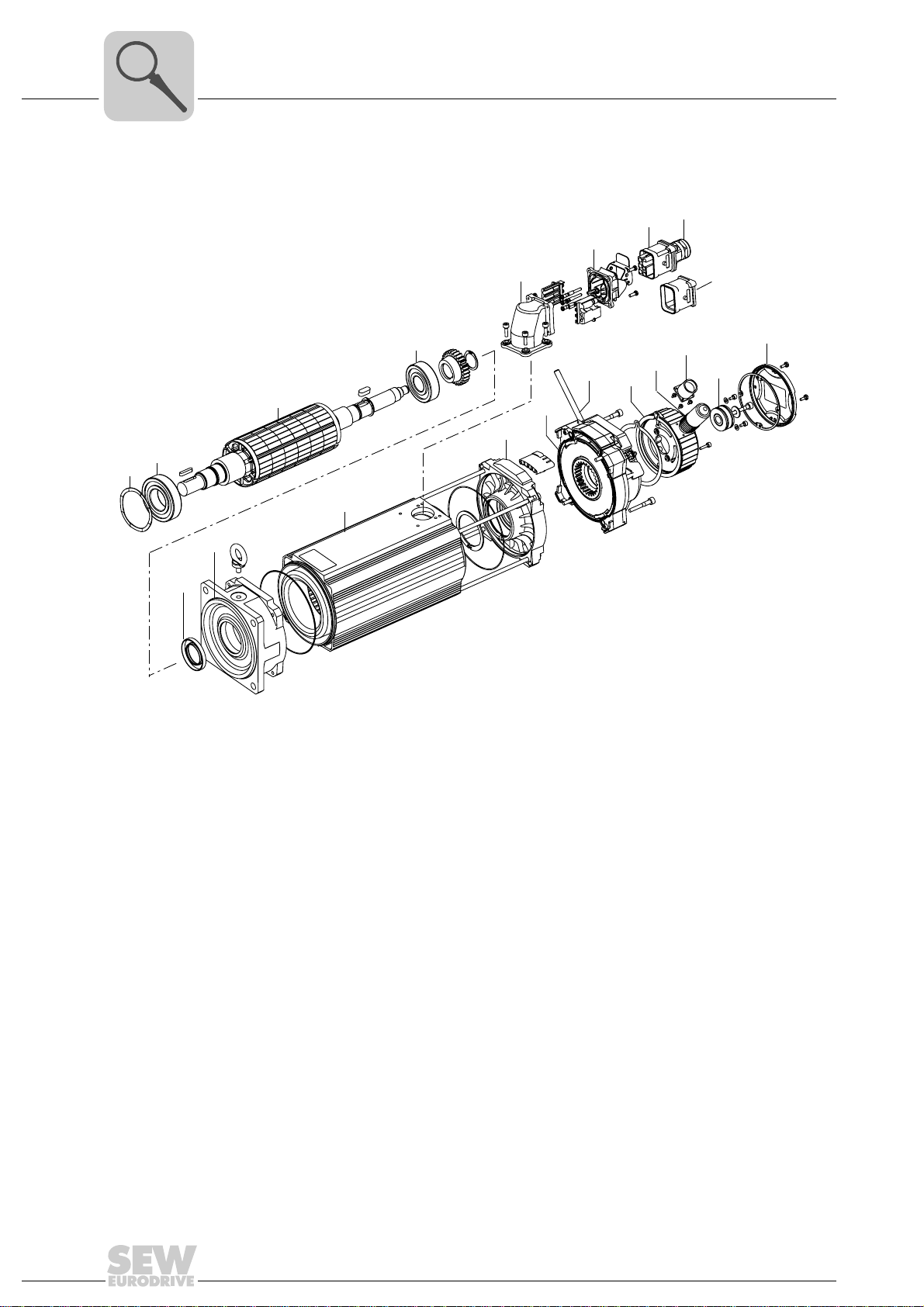
DFS synchronous servomotor – general structure
3 Motor Structure
TIP
The following illustrations are intended to explain the general structure. They are to
facilitate the assignment of components to the spare parts list. Deviations are possible
depending on the motor size and version!
3.1 DFS synchronous servomotor – general structure
Motor Structure
3
[316] [321] [1] [10][7] [11] [304]
[1] Rotor [304] Housing cover
[7] Flanged endshield [305] Resolver
[10] Retaining ring [313] Locking plate
[11] Grooved ball bearing [314] Pin contact power/brake
[16] Stator [316] Power connector, complete
[42] B-side endshield [318] Flange socket complete
[44] Grooved ball bearing [319] Pin contact signal
[106] Oil seal without key [321] Signal connector, complete
[220] Absolute encoder [550] Complete brake
[313]
[314]
[318]
[319]
[305][42][44][550][16][106]
AS1H / ES1H
[220]
[304]
413859723
Operating Instructions – DFS/CFM Synchronous Servomotors
Artisan Technology Group - Quality Instrumentation ... Guaranteed | (888) 88-SOURCE | www.artisantg.com
11
Page 13
3
Motor Structure
CFM synchronous servomotor – general structure
3.2 CFM synchronous servomotor – general structure
[313]
[316]
[317]
[105]
[11]
[106]
[7]
[1]
[16]
[44]
[42]
[312]
[550]
[660]
[737]
[321]
[327]
[304]
[318]
[305]
413861259
[1] Rotor [312] Connector housing
[7] Flanged endshield [313] Locking plate
[11] Grooved ball bearing [316] Power connector, complete
[16] Stator [317] Socket contact
[42] B-side endshield [318] Flange socket complete
[44] Grooved ball bearing [321] Signal connector, complete
[105] Shim washer [327] Cover
[106] Oil seal [550] Complete brake
[304] Housing cover [660] Release lever
[305] Resolver [737] Encoder housing
12
Operating Instructions – DFS/CFM Synchronous Servomotors
Artisan Technology Group - Quality Instrumentation ... Guaranteed | (888) 88-SOURCE | www.artisantg.com
Page 14

Nameplate, unit designation and serial number
3.3 Nameplate, unit designation and serial number
3.3.1 Nameplate
Example: CFM 71M /BR /TF /RH1M synchronous brake motor
76646 Bruchsal/Germany
Typ
CFM71M/BR/TF/RH1L/SB50
Nr.
01.1234567890.0001.07
M
Motor
0
n
N
U
Sys
Bremse
Getriebe
M
i
a pk
:1
Nm
6,5
r/min
3000
V
400
V
230
IM
B5
Nm
I
max
Iso.Kl.
Nm
14
n
a pk
I
0
A
4,3
17,2
Permanentmagnet
A
155 (F)
Gleichrichter
/
n
BME
e pk
Motor Structure
3 IEC60034
IP
65
˚C
-20...+40
r/min
13,0
kg
3
0199 081 0.13
3.3.2 DFS/CFM unit designations
Synchronous servomotors
DS... Motor for mounting to size 56 gear units
DFS... Size 56 in flange-mounted version
CM... Motor for mounting to gear units of sizes 71/90/112
CFM... Sizes 71/90/112 in flange-mounted version
Standard equipment for synchronous servomotors
/SM.0 Motor plug connector (socket on motor end only)
/SB.0 Plug connector motor + brake (socket on motor end only)
/RH1M Resolver
/RH1L Resolver for brake motors
/TF Thermistor (PTC resistor)
/KTY Temperature sensor
Umrichterbetrieb
Made in Germany
685748747
Operating Instructions – DFS/CFM Synchronous Servomotors
Artisan Technology Group - Quality Instrumentation ... Guaranteed | (888) 88-SOURCE | www.artisantg.com
13
Page 15
3
Motor Structure
Nameplate, unit designation and serial number
Synchronous servomotor options
/B Size 56 disk brake
/BR Size 71/90/112 disk brake
/HR . . manual brake release with automatic re-engaging function sizes 71/90/112
/SM.. Motor plug connector with code number for size and connection cross section
SB.. Plug connector for motor + brake with code number for size and connection cross section
®
/ES1H HIPERFACE
/AS1H HIPERFACE
/AV1H HIPERFACE
/AV1Y Multi-turn SSI encoder, solid shaft, size 56
/AK0H Multi-turn SSI encoder, solid shaft, size 56
/EK0H HIPERFACE
/VR Forced cooling fan
/KK Terminal box
/KK5 Terminal box for radial encoder
/KK6 Terminal box for axial encoder
single-turn encoder, spreadshaft, size 56/71/90/112
®
multi-turn encoder, spreadshaft, size 56/71/90/112
®
multi-turn encoder, solid shaft, size 56/71/90/112
®
single-turn encoder, spread shaft, size 56
3.3.3 Sample unit designation: DFS synchronous brake motor
DFS 56L /B /TF /RH1M /SM11
Plug connector (motor option)
Resolver as standard equipment
TF thermistor as standard equipment
Brake (motor option)
Size 56L
Flange-mounted motor DFS series
14
Operating Instructions – DFS/CFM Synchronous Servomotors
Artisan Technology Group - Quality Instrumentation ... Guaranteed | (888) 88-SOURCE | www.artisantg.com
Page 16

Nameplate, unit designation and serial number
3.3.4 Sample unit designation: CFM synchronous brake motor
CFM 112S /BR /TF /AS1H /SB50
3.3.5 Scope of delivery for SEW-EURODRIVE motors
The scope of delivery for SEW-EURODRIVE servomotors includes for standard mo-
tors:
Motor Structure
Plug connector as standard
Motor option HIPERFACE® multi-turn
encoder
TF thermistor as standard equipment
Brake (motor option)
Size 112S
Flange-mounted motor CFM series
3
Delivery with order confirmation
Delivery with drive 1 x Motor according to order confirmation
Pre-fabricated cable 1 x Bag with loose parts including conductor end sleeves and cable lugs for connection to
Forced cooling fan 1 x Power connector
Plug connector 1 x Encoder connector (radial or axial)
1 x Operating instructions in the language of the corresponding country, if requested. When ordering
several servo gear units, the customer can reduce the number of operating instructions.
1 x Safety notes for startup, if requested
1 x Spare parts list if requested
SEW-EURODRIVE inverters.
1 x Power socket
4 x Hex head screw
4 x Square nut
10 x Crimp socket contacts for encoder connector for core cross sections of 0.25 mm2 to 0.5 mm2.
1 x SM50 mating connector for motor power cable
4 x Crimp socket contacts for power connection for core cross sections of 1.5, 2.5, 4, 6 or 10 mm
2
Operating Instructions – DFS/CFM Synchronous Servomotors
Artisan Technology Group - Quality Instrumentation ... Guaranteed | (888) 88-SOURCE | www.artisantg.com
15
Page 17
3
Motor Structure
Nameplate, unit designation and serial number
The scope of delivery for SEW-EURODRIVE servomotors includes for brakemotors:
Delivery with order confirmation
Delivery with drive 1 x Motor according to order confirmation
Pre-fabricated cable 1 x Bag with loose parts including conductor end sleeves and cable lugs for connection to
Brake 1 x AC-operated BME brake rectifier for DIN rail mounting, or alternatively:
Forced cooling fan 1 x Power connector
Plug connector 1 x Encoder connector (radial or axial)
1 x Operating instructions in the language of the corresponding country, if requested. When ordering
several servo gear units, the customer can reduce the number of operating instructions.
1 x Safety notes for startup, if requested
1 x Spare parts list if requested
SEW-EURODRIVE inverters
- BMP, BMH or BMK brake rectifier
- BSG brake control unit at a voltage of DC 24 V
1 x Manual release lever if brake with manual release was ordered
1 x Power socket
4 x Hex head screw
4 x Square nut
4 x Mounting bracket
10 x Crimp socket contacts for encoder connector for core cross sections of 0.25 mm2 to 0.5 mm
1 x SB50 mating connector for motor power and brake cable
4 x Crimp socket contacts for power connection for core cross sections of 1.5, 2.5, 4, 6 or 10 mm
3 x Crimp socket contacts for brake connection for core cross sections of 1 mm2 or 1.5 mm
2
2
2
3.3.6 Example: Serial number
01. 301234568. 0001. 03
Final two digits of the year of manufacture
Unit serial number (4 digits)
Order number (10 digits)
Sales organization
16
Operating Instructions – DFS/CFM Synchronous Servomotors
Artisan Technology Group - Quality Instrumentation ... Guaranteed | (888) 88-SOURCE | www.artisantg.com
Page 18
4 Mechanical Installation
4.1 Required tools/resources
• Standard tools
• Mounting device
• Operation with conductor end sleeves: Crimping tool and conductor end sleeves
• Crimping tool for plug connectors
• Removal tool
4.2 Before you begin
The drive may only be installed if
• The specifications on the drive's nameplate and/or the output voltage of the
frequency inverter match the voltage supply system
• The drive is undamaged (no damage caused by transportation or storage).
Mechanical Installation
Required tools/resources
4
• You are certain that the following requirements have been fulfilled:
– Ambient temperature between –20 °C and +40 °C
– No oil, acid, gas, vapors, radiation, etc.
– Installation altitude max. 1000 m above sea level
– Special designs: Drive configured in accordance with the ambient conditions
4.3 Preliminary work
Motor shaft ends must be thoroughly cleaned of anti-corrosion agents, contamination or
similar (use a commercially available solvent). Make sure that the solvent does not come
into contact with the bearing or sealing rings as it may damage the material.
NOTICE
The bearing and the sealing rings can be damaged if exposed to solvents.
Potential damage to property.
• Protect the bearing and sealing rings from exposure to solvents.
4.3.1 Installation after extended storage
• Note that the service life of the lubricant in the ball bearings is reduced by 10% per
year after the first year of storage.
• Check whether the motor has absorbed moisture as a result of being stored for a long
time. Measure the insulation resistance for this purpose (measuring voltage
DC 500 V).
Operating Instructions – DFS/CFM Synchronous Servomotors
Artisan Technology Group - Quality Instrumentation ... Guaranteed | (888) 88-SOURCE | www.artisantg.com
17
Page 19
4
Mechanical Installation
Preliminary work
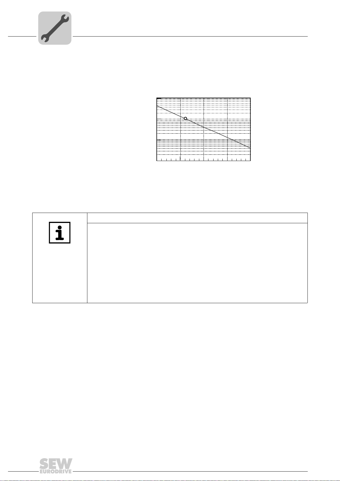
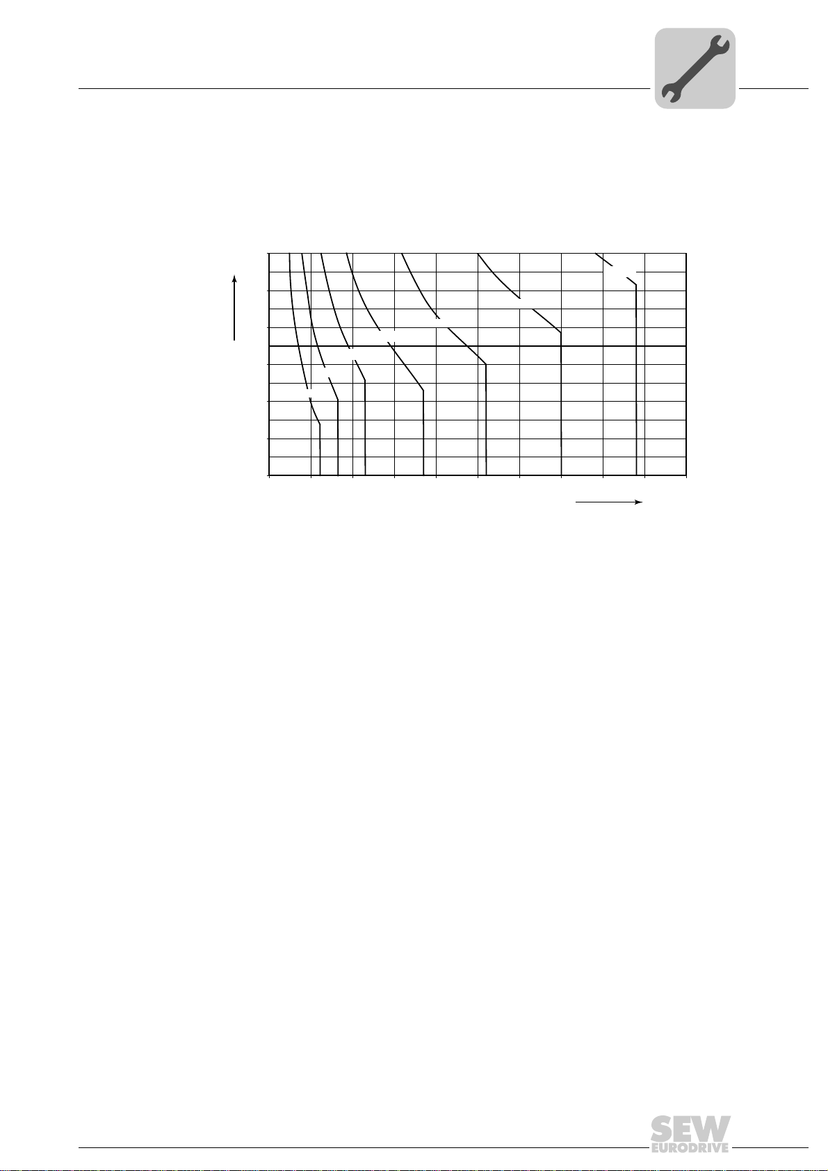
The insulation resistance (see following figure) varies greatly depending on the temperature. The motor must be dried if the insulation resistance is not adequate.
The following figure shows the insulation resistance depending on the temperature.
[MΩ]
100
4.3.2 Drying the motor
TIP
Insulation resistance too low:
→ Servomotor has absorbed moisture
Measure:
• Use hot air to heat up the motor.
• Open the motor compartment enough for moisture to escape from the inside.
Next check whether:
• The wiring space is dry and clean.
• The connections and fastening parts are free from corrosion.
• The joint seal is functioning.
• The cable glands are tight, otherwise clean or replace them.
10
0,1
[1]
1
0
20
40
60
80
[°C]
413914507
18
Operating Instructions – DFS/CFM Synchronous Servomotors
Artisan Technology Group - Quality Instrumentation ... Guaranteed | (888) 88-SOURCE | www.artisantg.com
Page 20

4.4 Installing the motor
NOTICE
Improper mounting may result in damages to the motor.
Potential damage to property.
• Only install the motor in the specified mounting position on a level, vibration-free,
and torsionally rigid support structure.
• Align the motor and the driven machine carefully to avoid placing any unacceptable
strain on the output shafts.
• Observe permitted overhung and axial loads → "Low Backlash Servo Gearmotors
(BSF.., PSF..)" catalog.
• Do not butt or hammer the shaft end.
NOTICE
Vertical designs with VR forced-cooling fan can get damaged by foreign objects or
moisture.
Potential damage to property.
• Protect vertical designs with VR forced-cooling fan with corresponding covers.
Mechanical Installation
Installing the motor
4
If a forced cooling fan is used, ensure there is sufficient clearance around the unit to
allow for adequate cooling. Make sure that the unit does not suck in hot outgoing air from
other units.
Components with a keyway to be mounted belatedly on the shaft must be balanced
using a half key. Motor shafts may be balanced with a half key (vibration level "N" to
EN/IEC 600 34). You must not operate the motor without a key.
Operating Instructions – DFS/CFM Synchronous Servomotors
Artisan Technology Group - Quality Instrumentation ... Guaranteed | (888) 88-SOURCE | www.artisantg.com
19
Page 21

4
Mechanical Installation
Mounting tolerances
4.4.1 Installation in damp locations or in the open
• Try to arrange the motor and encoder connection so that the connector cables do not
point upwards.
• Coat the threads of the cable glands and filler plugs with sealing compound and
tighten them properly. Then coat them again.
• Clean the sealing surfaces of the connector (motor and/or encoder connection)
before reassembly.
• Replace any brittle seals.
• If necessary, restore the anticorrosive paint coat.
• Check that the degree of protection is maintained.
4.5 Mounting tolerances
Shaft end Flanges
Diameter tolerance according to EN 50347
•ISO k6
• Center bore in accordance with DIN 332, shape
DR..
Centering shoulder tolerance in accordance with
EN 50347
•ISO j6
20
Operating Instructions – DFS/CFM Synchronous Servomotors
Artisan Technology Group - Quality Instrumentation ... Guaranteed | (888) 88-SOURCE | www.artisantg.com
Page 22

5 Electrical Installation
DANGER
Risk of injury due to electric shock.
Severe or fatal injuries.
• It is essential to comply with the safety notes in section 2 during installation.
• Use switch contacts in utilization category AC-3 to EN 60947-4-1 for connecting
the motor and the brake.
• When motors are powered from inverters, you must adhere to the wiring
instructions issued by the inverter manufacturer.
• Observe the operating instructions for the servo inverter.
5.1 Assembling the connector
NOTICE
If the connector is tightened when it is installed in the wrong position, the insulator could
slip, causing irreparable damage.
Potential damage to property.
Note the following when plugging in the power and signal connectors:
• Check that the connector is installed in the correct position.
• Check that the detent on the connector is positioned correctly.
• Make sure that the connector lock can be turned without having to apply too much
force.
Electrical Installation
Assembling the connector
5
5.2 Wiring notes
5.2.1 Protection against interference by brake controllers
Do not route unshielded brake cables alongside switched-mode power cables, since
brake controllers may cause interference.
Switched-mode power cables include in particular:
• Output cables from frequency inverters and servo inverters, converters, soft start
units and brake units
• Supply cables to braking resistors and similar.
5.2.2 Thermal motor protection
Install the connecting lead of the TF/KTY separately from other power cables, maintaining a distance of at least 200 mm. Collective installation is only permitted if either the
TF / KTY cable or the power cable is shielded.
Operating Instructions – DFS/CFM Synchronous Servomotors
Artisan Technology Group - Quality Instrumentation ... Guaranteed | (888) 88-SOURCE | www.artisantg.com
21
Page 23

5
Electrical Installation
Connecting the motor and encoder system using SM../SB.. plug connectors
5.3 Connecting the motor and encoder system using SM../SB.. plug connectors
The DFS/CFM motors are supplied with the SM../SB.. plug connector system. In the
basic version, SEW-EURODRIVE delivers DFS/CFM motors with a flange socket on the
motor end and without mating connector. The encoder system is connected using a separate 12-pin round plug connector. The standard encoder cable entry is axial for the DFS
motor and radial for the CFM motor.
5.3.1 Cable cross section
Make sure that the type of cable complies with the applicable regulations. The rated currents are specified on the nameplate. The cable cross sections that can be used are
listed in the following table.
Typ e Cable type Cable cross section
[mm2] [AWG]
SM11/SM51/SM61
SM52/SM62 4 x 2.5 mm
SM54/SM64 4 x 4 mm
SM56/SM66 4 x 6 mm
SM59/SM69 4 x 10 mm
SB11
SB51/SB61 4 x 1.5 mm
SB52/SB62 4 x 2.5 mm
SB54/SB64 4 x 4 mm
SB56/SB66 4 x 6 mm
SB59/SB69 4 x 10 mm
Motor cable
Brakemotor cable
4 x 1.5 mm
4 x 1.5 mm
2
2
2
2
2
2
+ 2 x 1 mm
2
+ 3 x 1 mm
2
+ 3 x 1 mm
2
+ 3 x 1 mm
2
+ 3 x 1.5 mm
2
+ 3 x 1.5 mm
2
AWG 16
AWG 14
AWG 12
AWG 10
AWG 8
2
AWG 16 + AWG 18
2
AWG 16 + AWG 18
2
AWG 14 + AWG 18
AWG 12 + AWG 18
2
AWG 10 + AWG 16
2
AWG8 + AWG16
5.3.2 Prefabricated cables
Pre-fabricated cables are available from SEW-EURODRIVE to connect the SM../SB..
plug connector system. The core designation and contact assignment are listed in the
following tables.
Observe the following when you assemble the cables yourself:
• Section 10 describes the assembly of the SM1./SB1., SM5./SM6., SB5./SB6 power
connectors and the signal connector.
• The socket contacts for the motor connection are designed as crimp contacts. Only
use suitable tools for crimping.
• Strip the insulation of the leads according to section 10.
• Use suitable removal tools to remove incorrectly installed socket contacts.
• Install the insulator in the signal connectors on the motor end at "zero" degree (center
position). Observe this coding on the cable end.
• Cable relief according to EN 61984 and EN 60529 is influenced by the tightening
torque of the screw. The tightening torque must be matched to the cable.
22
Operating Instructions – DFS/CFM Synchronous Servomotors
Artisan Technology Group - Quality Instrumentation ... Guaranteed | (888) 88-SOURCE | www.artisantg.com
Page 24
Dimensioning the cable cross section
5.4 Dimensioning the cable cross section
5.4.1 Cable dimensioning according to EN 60402
The following figure shows the minimum required cable cross section depending on
cable length l [m] and current I [A].
150
130
110
100
90
70
50
2,5 mm²
1,5 mm²
6 mm²
4 mm²
10 mm²
Electrical Installation
25 mm²
16 mm²
5
30
010 2030405060708090100
Hybrid cables with cross sections of 1.5 mm
dered from SEW-EURODRIVE.
I [A]
576701195
2
(AWG 16) to 10 mm2 (AWG 8) can be or-
Operating Instructions – DFS/CFM Synchronous Servomotors
Artisan Technology Group - Quality Instrumentation ... Guaranteed | (888) 88-SOURCE | www.artisantg.com
23
Page 25
5
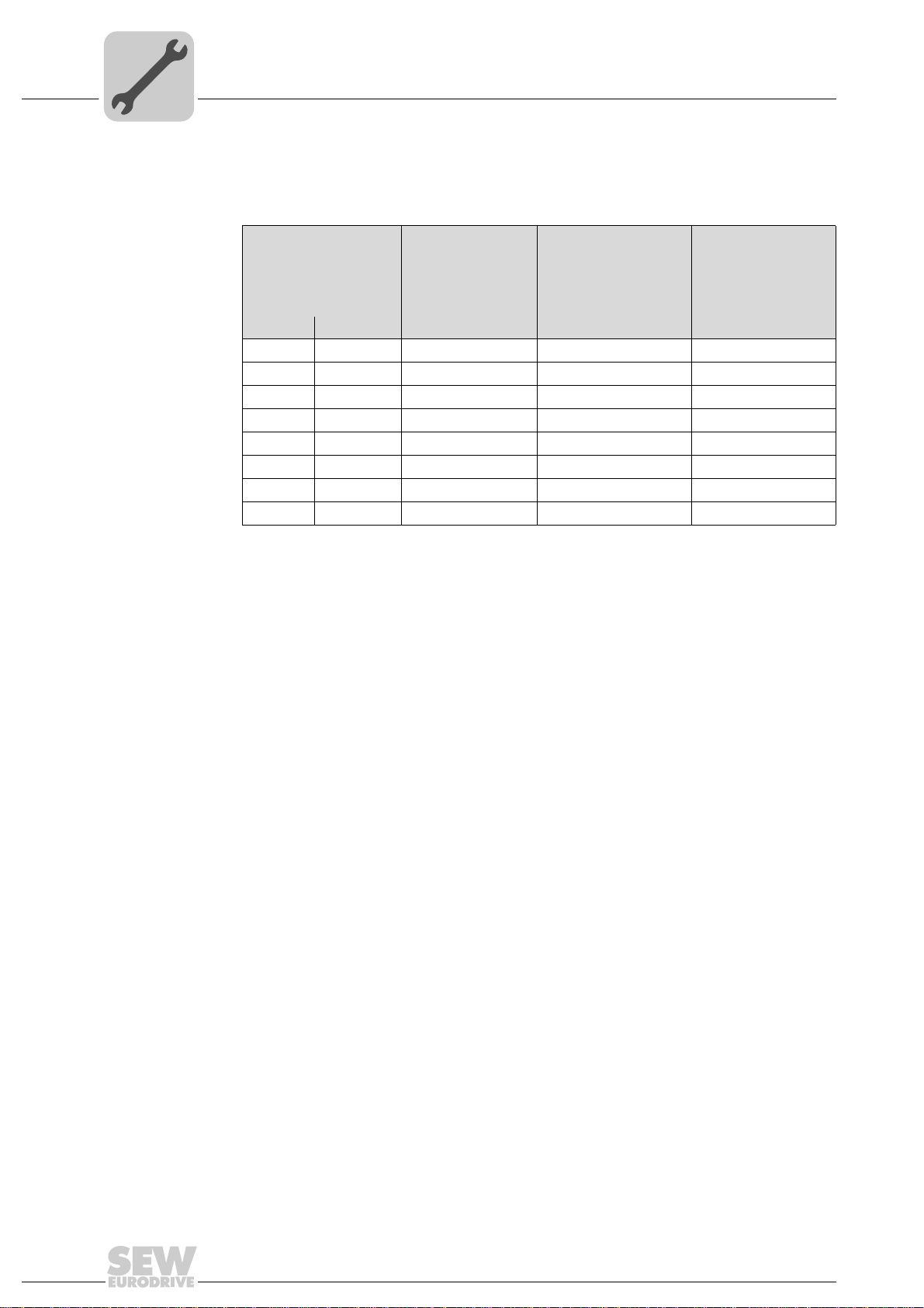
5.4.2 Cable load table
Electrical Installation
Dimensioning the cable cross section
Cable load through current I in [A] according to EN 60204-1 table 5, ambient temperature 40 °C.
Triple-core, plas-
Cable cross section
[mm2] [AWG] [A] [A] [A]
1,5 AWG 16 12,2 15,2 16,1
2,5 AWG 14 16,5 21,0 22
4 AWG 12 23 28,0 30
6 AWG 10 29 36,0 37
10 AWG 8 40 50,0 52
16 AWG 6 53 66,0 70
25 AWG 4 67 84,0 88
35 AWG 2 83 104,0 114
tic-sheathed cable
in
Duct or cable
Triple-core, plastic-
sheathed cable on
top of each other on
wall
Triple-core, plastic-
sheathed cable
next to each other,
horizontal
These data are merely recommended values and are no substitute for the detailed
project planning of the cables depending on the concrete application considering the
applicable regulations.
Observe the voltage drop that occurs along the cable in particular with the DC 24 V
brake coil when dimensioning the cross sections for the brake cable. The accelerator
current is decisive for the calculation.
24
Operating Instructions – DFS/CFM Synchronous Servomotors
Artisan Technology Group - Quality Instrumentation ... Guaranteed | (888) 88-SOURCE | www.artisantg.com
Page 26
Dimensioning the cable cross section
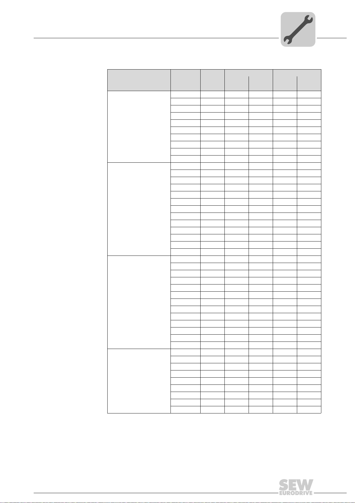
5.4.3 Assignment of servomotor and cable cross section
Electrical Installation
5
Rated speed nN [rpm] Motor
CFM71S 5 2.2 51 / 61 3.95 51 / 61
CFM71M 6.5 3 51 / 61 5.3 51 / 61
CFM71L 9.5 4.2 51 / 61 7.4 52 / 62
CFM90S 11 4.9 51 / 61 8.7 52 / 62
2000
3000
4500
6000
1) For UL application only with terminal box
CFM90M 14.5 6.9 51 / 61 12.1 54 / 64
CFM90L 21 9.9 51 / 61 17.1 56 / 66
CFM112S 23.5 10 51 / 61 18.0 56 / 66
CFM112M 31 13.5 52 / 62 24.5 59 / 69
CFM112L 45 20 54 / 64 35.5 59 / 69
CFM112H 68 30.5 59 / 69 – –
DFS56M 1 1.65111.6511
DFS56L 22.4112.411
DFS56H 42.811 – –
CFM71S 5 3.3 51 / 61 5.9 51 / 61
CFM71M 6.5 4.3 51 / 61 7.6 52 / 62
CFM71L 9.5 6.2 51 / 61 11.1 54 / 64
CFM90S 11 7.3 51 / 61 12.7 54 / 64
CFM90M 14.5 10.1 51 / 61 17.4 56 / 66
CFM90L 21 14.4 52 / 62 25.5 59 / 69
CFM112S 23.5 15 52 / 62 27 59 / 69
CFM112M 31 20.5 54 / 64 35 59 / 69
CFM112L 45 30 59 / 69 48 –
CFM112H 68 43 – – –
DFS56M 11.6511 – –
DFS56L 22.411 – –
DFS56H 4411––
CFM71S 5 4.9 51 / 61 8.5 52 / 62
CFM71M 6.5 6.6 51 / 61 11.3 54 / 64
CFM71L 9.5 9.6 51 / 61 17.1 56 / 66
CFM90S 11 11.1 51 / 61 18.9 56 / 66
CFM90M 14.5 14.7 52 / 62 26 59 / 69
CFM90L 21 21.6 54 / 64 39 59 / 69
CFM112S 23.5 22.5 54 / 64 38.5 59 / 69
CFM112M 31 30 56 / 66 54 –
CFM112L 45 46 59 / 69
CFM112H 68 66 – – –
DFS56M 11.6511 – –
DFS56L 22.7511 – –
DFS56H 45.311 – –
CFM71S 5 6.5 51 / 61 11.6 54 / 64
CFM71M 6.5 8.6 51 / 61 14.1 54 / 64
CFM71L 9.5 12.5 52 / 62 21.5 59 / 69
CFM90S 11 14.5 52 / 62 23.5 59 / 69
CFM90M 14.5 19.8 54 / 64 37 59 / 69
CFM90L 21 29.5 56 / 66 51 –
M
[Nm]
0
400 V 230 V
I
0
[A] [A]
SM
SB
I
1)
––
0
SM
SB
1)
1)
1)
1)
The suggested cross sections for 230 V are sufficient for NFPA 79 and UL 508
(without 1). Further DFS/230 V motor variants are available on request
Operating Instructions – DFS/CFM Synchronous Servomotors
Artisan Technology Group - Quality Instrumentation ... Guaranteed | (888) 88-SOURCE | www.artisantg.com
25
Page 27
5
Electrical Installation
Dimensioning the cable cross section
TIP
The assignments of SM/SB plug connectors are not binding. Given the dynamic properties in the system, other cross sections can also be implemented.
26
Operating Instructions – DFS/CFM Synchronous Servomotors
Artisan Technology Group - Quality Instrumentation ... Guaranteed | (888) 88-SOURCE | www.artisantg.com
Page 28
Electrical Installation
Power cables for DFS motors
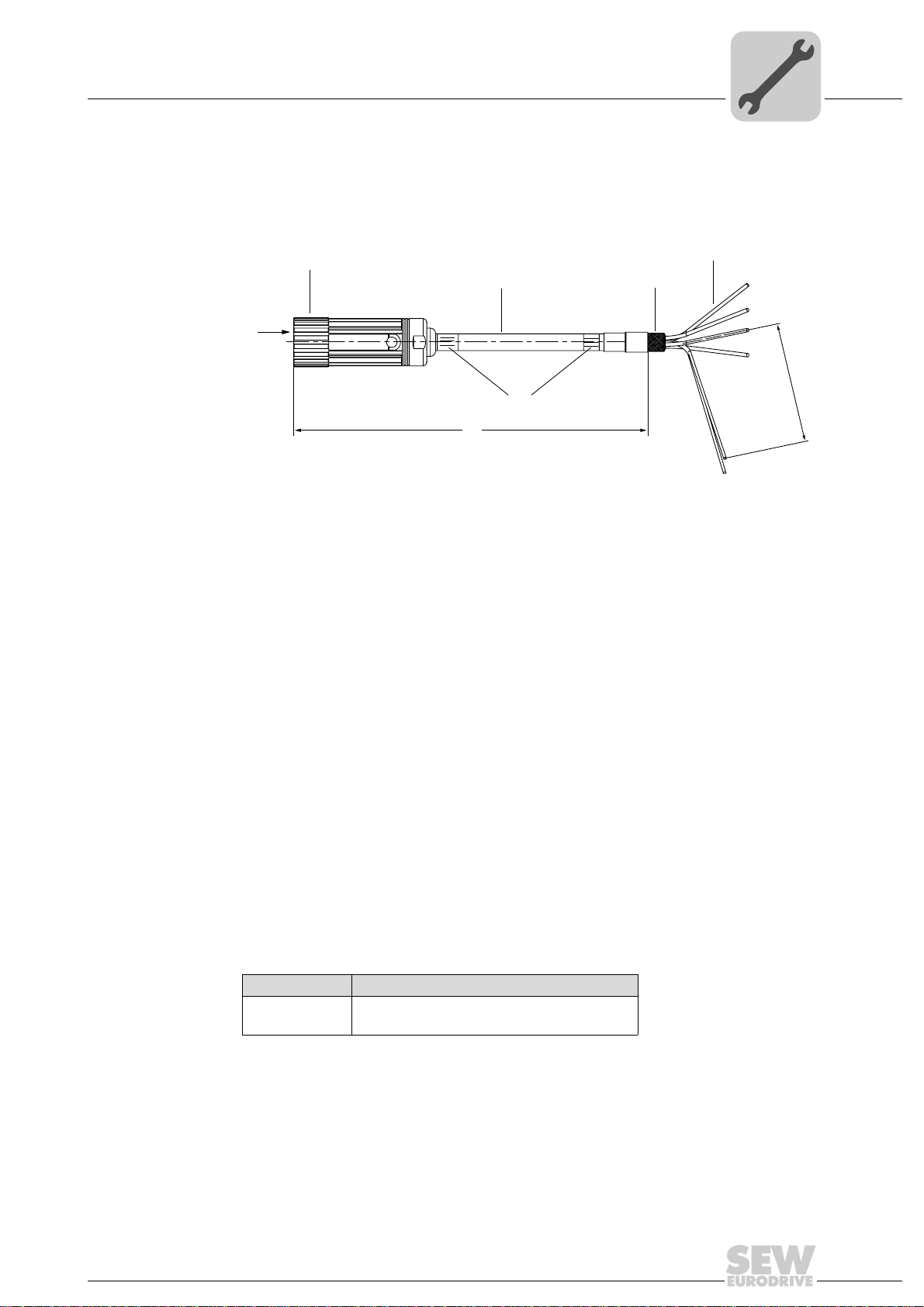
5.5 Power cables for DFS motors
5.5.1 Structure of the motor cables and brakemotor cables for DFS motors
The following figure shows the structure of the motor cables and brakemotor cables:.
5
[1]
[2]
X
[3]
[4]
Connector: Intercontec BSTA 078
[1]
SEW-EURODRIVE logo printed on cable
[2]
Nameplate
[3]
Cable length ≤ 10 m: Tolerance +200 mm
[4]
Cable length ≥ 10 m: Tolerance +2%
Permitted line length according to the technical documents.
Prefabricated cable end for inverter
[5]
Required loose parts are supplied with the cable.
Shielding 20 mm, pulled back approximately + 5 mm
[6]
[5]
[6]
500 ±5
413916043
Motor side The motor cables on the motor side consist of an 8-pin plug connector and socket con-
tacts.
The shield is connected in the connector housing according to EMC requirements. All
plug connectors seal the plug on the cable end with a lamellar seal and ensure cable
relief according to EN 61884.
Inverter side The individual cable cores of the motor and brakemotor cables are exposed and the
shield is prepared for connection in the control cabinet. The cable for the inverter end
has yet to be assembled. The loose parts required are supplied with the cable in a separate bag.
Loose parts The following loose parts are supplied in accordance with the core cross sections for
connection to the power terminals on the inverter:
Bag no. Content
2
1
4 x conductor end sleeves 1.5 mm
4 x M6 U-shaped cable lugs 1.5 mm
, insulated
2
Operating Instructions – DFS/CFM Synchronous Servomotors
Artisan Technology Group - Quality Instrumentation ... Guaranteed | (888) 88-SOURCE | www.artisantg.com
27
Page 29

5
Electrical Installation
Power cables for DFS motors
5.5.2 Motor cable for DFS motors
DFS motor cable
X
DFS motor cable types
413917579
Plug connector type Number of cores and cable cross
SM11 4 × 1.5 mm
SM11 4 × 1.5 mm
DFS motor cable – pin assignment
Plug connector
View X
BSTA 078
0198 6740
8-pole with
socket contacts
W1
PE
2
V1
U1
section
2
(AWG 16) Fixed installation 0590 4544
2
(AWG 16) Cable carrier
Pin Cable core color Assigned Extra
1 (BK) Black U Bag of loose
2 (GN/YE) Green/yellow PE
3 (BK) Black W
4 (BK) Black V
D
3
C
4
B
A
1
Installation Part number
installation
0590 6245
parts
DFS motor cable – alternative plug connector
Plug connectors for power supply with socket contacts (complete).
Plug connector type Number of cores and cable
SM11 4 × 1.5 mm
28
Artisan Technology Group - Quality Instrumentation ... Guaranteed | (888) 88-SOURCE | www.artisantg.com
cross section
2
Operating Instructions – DFS/CFM Synchronous Servomotors
(AWG 16)
Installation
Fixed installation /
cable carrier installa-
tion
Part number
0198 6740
Page 30
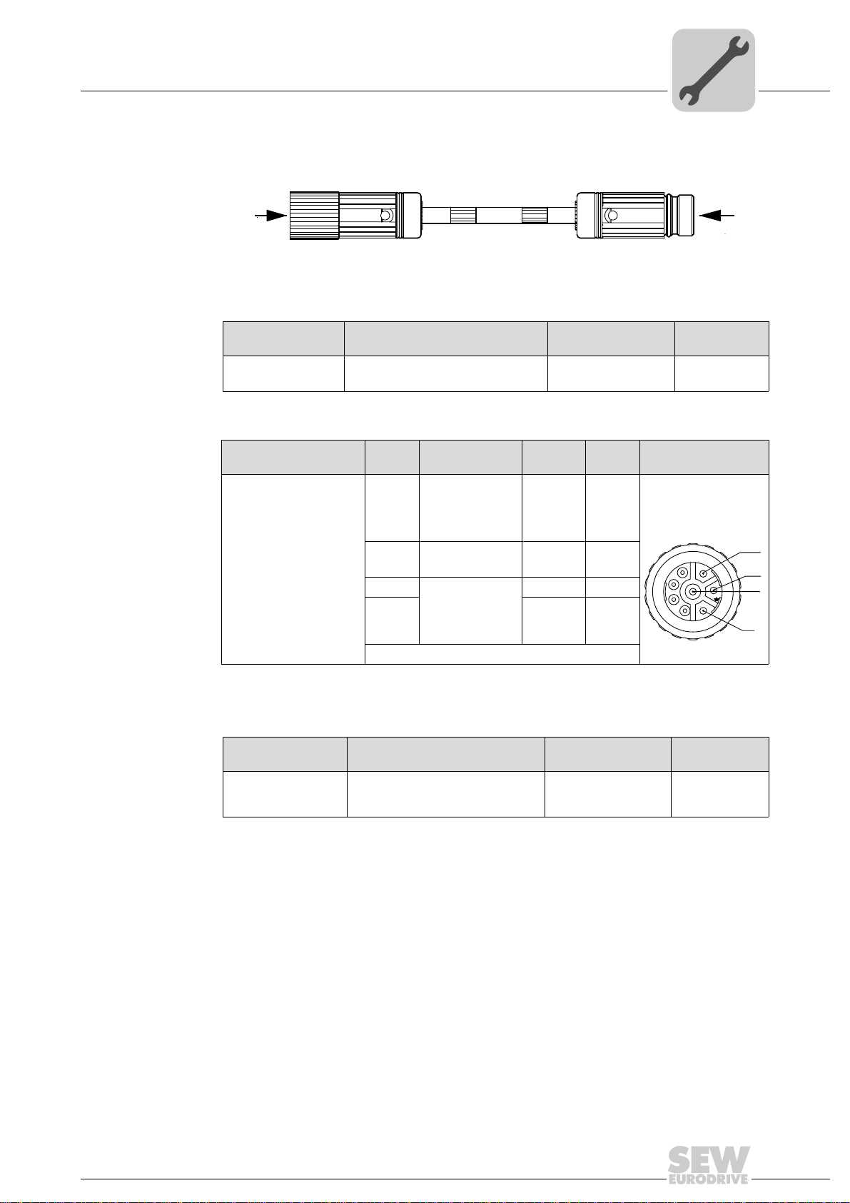
5.5.3 DFS motor cable – extension cable
Y
Extension cable for DFS motor cable:
X
DFS motor cable – types of extension cables
Electrical Installation
Power cables for DFS motors
5
413920651
Plug connector type Number of cores and cable cross
section
2
SM11 4 × 1.5 mm
(AWG 16)
DFS motor extension cable – pin assignment
Plug connector
View X
BSTA 078
0198 6740
8-pin with socket contacts
Pin Cable core color Assigned Pin Plug connector
(BK/WH)
1
Black with
white lettering
U, V, W
2
(GR/YE)
Green/yellow
3(BK/WH)
4V4
Black with
white lettering
U, V, W
Extension cable for DFS motor cable – alternative plug connector
Plug connector with pins (complete) for motor extension cable.
Installation Part number
Cable carrier
installation
1333 2457
View Y
BKUA 199
U1
PE 2
W3
1333 2430
8-pin with pin contacts
D
3
C
4
2
B
1
A
W/3
PE
V/2
U/1
Plug connector type Number of cores and cable cross
section
2
SM11 4 × 1.5 mm
(AWG 16)
Installation
Fixed installation /
cable carrier installa-
tion
Part number
1333 2430
Operating Instructions – DFS/CFM Synchronous Servomotors
Artisan Technology Group - Quality Instrumentation ... Guaranteed | (888) 88-SOURCE | www.artisantg.com
29
Page 31

5
Electrical Installation
Power cables for DFS motors
5.5.4 Brakemotor cable for DFS motors
DFS brakemotor cable:
X
DFS brakemotor cable types
413939083
Plug connector type Number of cores and cable cross
SB11
SB11
DFS brakemotor cable – pin assignment
Plug connector
View X
BSTA 078
0198 6740
0198 9197
8-pin with socket contacts
W1
PE
V1
U1
D
3
C
4
2
B
1
A
section
4 × 1.5 mm
2 × 1 mm
4 × 1.5 mm
2 × 1 mm
BK/-
BK/+
Installation Part number
2
(AWG 16) +
2
(AWG 18)
2
(AWG 16) +
2
(AWG 18)
Fixed installation 1332 4853
Cable carrier
installation
1333 1221
Pin Cable core color Assigned Extra
1(BK/WH)
U
Black with white letter-
ing U, V, W
2
3(BK/WH)
4V
(GN/YE)
Green/yellow
Black with white letter-
ing U, V, W
PE
W
Bag of loose
parts
A– n. c.
B– n. c.
C(BK/WH)
D1
Black with white letter-
ing 1, 2
2
DFS brakemotor cable – alternative plug connector
Plug connectors for power supply with socket contacts (complete).
Plug connector
type
SM11/SB11
SM11/SB11
30
Artisan Technology Group - Quality Instrumentation ... Guaranteed | (888) 88-SOURCE | www.artisantg.com
Number of cores and cable
cross section
2
4 × 1.5 mm
3 × 1 mm
4 × 1.5 mm
3 × 1 mm
(AWG 16) +
2
(AWG 18)
2
(AWG 16) +
2
(AWG 18)
Operating Instructions – DFS/CFM Synchronous Servomotors
Installation
Part number
Fixed installation 0198 6740
Cable carrier installation
0198 9197
Page 32

5.5.5 Brakemotor extension cable for DFS motors
Y
Brakemotor extension cable:
X
Types of brakemotor extension cables for DFS motors
Electrical Installation
Power cables for DFS motors
5
413920651
Plug connector type Number of cores and cable cross
section
SB11
4 × 1.5 mm
2 × 1 mm
DFS brakemotor extension cable – pin assignment
Plug connector
View X
BSTA 078
0198 9197
8-pin with socket con-
tacts
W1
PE
V1
U1
D
3
C
4
2
1
A
BK/-
B
Pin Cable core color Assigned Pin Plug connector
1 Black with
2
BK/+
3 Black with
4V4
A–n. c.A
B–n. c.B
C Black with white let-
D1D
2
(AWG 16) +
2
(AWG 18)
white lettering
U, V, W
(BK/WH)
Green/yellow
(GN/YE)
white lettering
U, V, W
(BK/WH)
tering 1, 2, 3
(BK/WH)
Installation Part number
Cable carrier
installation
1333 2481
View Y
U1 BKUA 199
1333 2430
8-pin with pin contacts
PE 2
W3
BK/+
BK/–
D
3
C
4
B
1
A
2C
W/3
PE
V/2
2
U/1
Plug connector with pins (complete) for brakemotor extension cable.
Plug connector type Number of cores and cable
cross section
2
SM11/SB11 4 × 1.5 mm
2 × 1 mm
Operating Instructions – DFS/CFM Synchronous Servomotors
Artisan Technology Group - Quality Instrumentation ... Guaranteed | (888) 88-SOURCE | www.artisantg.com
(AWG 16) +
2
(AWG 18)
Installation
Cable carrier installation
Part number
1333 2430
31
Page 33

5
Electrical Installation
Power cables for CFM motors
5.6 Power cables for CFM motors
5.6.1 Structure of the motor cables and brakemotor cables for CFM motors
The following figure shows the structure of the motor cables and brakemotor cables:
[1]
X
[2]
[5]
Connector: Amphenol
[1]
SEW-EURODRIVE logo printed on cable
[2]
Nameplate
[3]
Cable length ≤ 10 m: Tolerance +200 mm
[4]
Cable length ≥ 10 m: Tolerance +2%
Permitted line length according to the technical documents.
Prefabricated cable end for inverter
[5]
Required loose parts are supplied with the cable.
Shielding 20 mm, pulled back approximately + 5 mm
[6]
[3]
[4]
[6]
574170891
Motor side The cables on the motor end have a 6-pin EMC Amphenol plug connector and socket
contacts.
The shield is connected in the connector housing according to EMC requirements. All
plug connectors seal the plug on the cable end with a lamellar seal and ensure cable
relief according to EN 61884.
Inverter side The individual cable cores of the motor and brakemotor cables are exposed and the
shield is prepared for connection in the control cabinet. The cable for the inverter end
has yet to be assembled. The loose parts required are supplied with the cable in a separate bag.
Loose parts The following loose parts are supplied in accordance with the core cross sections for
connection to the power terminals on the inverter:
32
Bag no. Content
1
2
3
4
5
4 x conductor end sleeves 1.5 mm
4 x M6 U-shaped cable lugs 1.5 mm
4 x conductor end sleeves 2.5 mm
4 x M6 U-shaped cable lugs 2.5 mm
4 x conductor end sleeves 4 mm
4 x M6 U-shaped cable lugs 4 mm
4 x M10 U-shaped cable lugs 4 mm
4 x M6 U-shaped cable lugs 6 mm
4 x M10 U-shaped cable lugs 6 mm
4 x M6 U-shaped cable lugs 10 mm
4 x M10 ring-type cable lugs 10 mm
Operating Instructions – DFS/CFM Synchronous Servomotors
Artisan Technology Group - Quality Instrumentation ... Guaranteed | (888) 88-SOURCE | www.artisantg.com
2
, insulated
2
2
, insulated
2
2
, insulated
2
2
2
2
2
2
Page 34

5.6.2 Motor cable for CFM motors
CFM motor cable:
X
Types of CFM motor cables
The cables are equipped with a connector for motor connection and conductor end
sleeves for inverter connection.
Electrical Installation
Power cables for CFM motors
5
413946763
Plug connector type Number of cores and cable cross
SM51/SM61 4 × 1.5 mm
SM52/SM62 4 × 2.5 mm
SM54/SM64 4 × 4 mm
SM56/SM66 4 × 6 mm
SM59/SM69 4 × 10 mm
SM51/SM61 4 × 1.5 mm
SM52/SM62 4 × 2.5 mm
SM54/SM64 4 × 4 mm
SM56/SM66 4 × 6 mm
SM59/SM69 4 × 10 mm
CFM motor cable – pin assignment
Plug connector
View X
C148U connector
with socket contacts
section
2
(AWG 16)
2
(AWG 14) 0199 1817
2
(AWG 12) 0199 1833
2
(AWG 10) 0199 185X
2
(AWG 8) 0199 1876
2
(AWG 16)
2
(AWG 14) 1333 1159
2
(AWG 12) 0199 1841
2
(AWG 10) 0199 1868
2
(AWG 8) 0199 1884
Pin Cable core color Assigned Pin Extra
U1 (BK/WH)
V1 V
W1 W
PE
Black with
white lettering
U, V, W
(GN/YE)
Green/yellow
Installation Part number
Fixed installation
Cable carrier
installation
U
Cut-off, length about
250 mm
(protec-
tive earth)
With Phoenix plug
connector
GMVSTBW 2.5/3 ST
0199 1795
1333 1140
loose parts
Bag of
4
3
5
Operating Instructions – DFS/CFM Synchronous Servomotors
Artisan Technology Group - Quality Instrumentation ... Guaranteed | (888) 88-SOURCE | www.artisantg.com
33
Page 35

5
Electrical Installation
Power cables for CFM motors
CFM motor cable – alternative plug connector
Plug connectors for power supply with socket contacts (complete):
Plug connector type Cross sections Installation Part number
SM51/SM61 4 × 1.5 mm
SM52/SM62 4 × 2.5 mm
SM54/SM64 4 × 4 mm
SM56/SM66 4 × 6 mm
SM59/SM69 4 × 10 mm
2
(AWG 16) Fixed installation / cable
2
(AWG 14) 0199 1361
2
(AWG 12) 0199 137X
2
(AWG 10) 0199 1388
2
(AWG 8) 0199 1396
carrier installation
0199 1353
34
Operating Instructions – DFS/CFM Synchronous Servomotors
Artisan Technology Group - Quality Instrumentation ... Guaranteed | (888) 88-SOURCE | www.artisantg.com
Page 36

5.6.3 CFM motor cable – extension cable
Y
CFM motor extension cable:
X
CFM motor cable – types of extension cables
The cables are equipped with a plug and adapter for extending the CFM motor cable.
Electrical Installation
Power cables for CFM motors
5
413950219
Plug connector type Number of cores and cable cross
section
SM51/SM61 4 × 1.5 mm
SM52/SM62 4 × 2.5 mm
SM54/SM64 4 × 4 mm
SM56/SM66 4 × 6 mm
SM59/SM69 4 × 10 mm
SM51/SM61 4 × 1.5 mm
SM52/SM62 4 × 2.5 mm
SM54/SM64 4 × 4 mm
SM56/SM66 4 × 6 mm
SM59/SM69 4 × 10 mm
CFM motor extension cable – pin assignment
Plug connector
View X
C148U connector with
socket contacts
Installation Part number
2
(AWG 16)
2
(AWG 14) 0199 5510
2
(AWG 12) 0199 5537
2
(AWG 10) 0199 5553
2
(AWG 8) 0199 557X
2
(AWG 16)
2
(AWG 14) 1333 1191
2
(AWG 12) 0199 5545
2
(AWG 10) 0199 5561
2
(AWG 8) 0199 5588
Pin Core identification Pin Plug connector
U1 (BK/WH)
V1 V1
W1 W1
Black with
white lettering
U, V, W
Fixed installation
Cable carrier
installation
U1
0199 5499
1333 1183
View Y
C148U adapter with pin
contacts
PE
4
3
5
The motor extension cable has the same pin assignment as all other contacts.
Operating Instructions – DFS/CFM Synchronous Servomotors
Artisan Technology Group - Quality Instrumentation ... Guaranteed | (888) 88-SOURCE | www.artisantg.com
(GN/YE)
Green/yellow
PE
35
Page 37

5
Electrical Installation
Power cables for CFM motors
Extension cable for CFM motor cable – alternative plug connector
Plug connector for power supply with pins (complete).
Plug connector type Cross sections Installation Part number
SM51/SM61 4 × 1.5 mm
SM52/SM62 4 × 2.5 mm
SM54/SM64 4 × 4 mm
SM56/SM66 4 × 6 mm
SM59/SM69 4 × 10 mm
2
(AWG 16) Fixed installation / cable
2
(AWG 14) 0199 5650
2
(AWG 12) 0199 5669
2
(AWG 10) 0199 5677
2
(AWG 8) 0199 5685
carrier installation
0199 5642
36
Operating Instructions – DFS/CFM Synchronous Servomotors
Artisan Technology Group - Quality Instrumentation ... Guaranteed | (888) 88-SOURCE | www.artisantg.com
Page 38

5.6.4 Brakemotor cable for CFM motors
CFM brakemotor cable:
X
CFM brakemotor cable types
Electrical Installation
Power cables for CFM motors
5
500 ±5
413954827
Plug connector type,
complete
SB51/SB61
SB52/SB62
SB54/SB64
SB56/SB66
SB59/SB69
SB51/SB61
SB52/SB62
SB54/SB64
SB56/SB66
SB59/SB69
Number of cores and cable cross
section
2
4 × 1.5 mm
3 × 1.0 mm
4 × 2.5 mm
3 × 1.0 mm
4 × 4 mm
3 × 1.0 mm
4 × 6 mm
3 × 1.5 mm
4 × 10 mm
3 × 1.5 mm
4 × 1.5 mm
3 × 1.0 mm
4 × 2.5 mm
3 × 1.0 mm
4 × 4 mm
3 × 1.0 mm
4 × 6 mm
3 × 1.5 mm
4 × 10 mm
3 × 1.5 mm
(AWG 16) +
2
(AWG 18)
2
(AWG 14) +
2
(AWG 18)
2
(AWG 12) +
2
(AWG 18)
2
(AWG 10) +
2
(AWG 16)
2
(AWG 8) +
2
(AWG 16)
2
(AWG 16) +
2
(AWG 18)
2
(AWG 14) +
2
(AWG 18)
2
(AWG 12) +
2
(AWG 18)
2
(AWG 10) +
2
(AWG 16)
2
(AWG 8) +
2
(AWG 16)
Installation Part number
0199 1892
0199 1914
Fixed installation
Cable carrier
installation
0199 1930
0199 1957
0199 1973
1333 1167
1333 1175
0199 1949
0199 1965
0199 1981
Operating Instructions – DFS/CFM Synchronous Servomotors
Artisan Technology Group - Quality Instrumentation ... Guaranteed | (888) 88-SOURCE | www.artisantg.com
37
Page 39

5
Electrical Installation
Power cables for CFM motors
CFM brakemotor cable – pin assignment
The brakemotor cable is prefabricated for the following brake resistors:
•BME
•BMP
•BMH
•BMK
•BMV
For the BSG control unit, the customers have to assemble the cable themselves.
Plug connector
View X
C148U connector
with socket contacts
Pin Core identifica-
U1 Black with
V1 V
W1 W
PE
3 Black with
42
53
CFM brakemotor cable – alternative plug connector
Plug connectors for power supply with socket contacts (complete).
Typ e Cross sections Installation Part number
SB51/SB61 4 × 1.5 mm
3 × 1.0 mm
SB52/SB62 4 × 2.5 mm
3 × 1.0 mm
SB54/SB64 4 × 4 mm
3 × 1.0 mm
SB56/SB66 4 × 6 mm
3 × 1.5 mm
SB59/SB69 4 × 10 mm
3 × 1.5 mm
2
2
2
2
2
(AWG 12) +
2
2
(AWG 10) +
2
2
(AWG 8) +
2
tion
white lettering
U, V, W
(BK/WH)
Green/yellow
(GN/YE)
white lettering
1, 2, 3
(BK/WH)
(AWG 16) +
(AWG 18)
(AWG 14) +
(AWG 18)
(AWG 18)
(AWG 16)
(AWG 16)
Assigned Contact type Extra
U
Cut-off, length about
250 mm
(protec-
tive earth)
1
Fixed installation / cable
carrier installation
With Phoenix plug
connector
GMVSTBW 2,5/3ST
0199 1426
0199 1434
0199 1442
0199 1450
0199 1469
Bag of loose
parts
38
Operating Instructions – DFS/CFM Synchronous Servomotors
Artisan Technology Group - Quality Instrumentation ... Guaranteed | (888) 88-SOURCE | www.artisantg.com
Page 40

5.6.5 Brakemotor extension cable for CFM motors
Y
CFM brakemotor extension cable
X
Types of brakemotor extension cables for CFM motors
Electrical Installation
Power cables for CFM motors
5
413950219
Plug connector type,
complete
SB51/SB61
SB52/SB62
SB54/SB64
SB56/SB66
SB59/SB69
SB51/SB61
SB52/SB62
SB54/SB64
SB56/SB66
SB59/SB69
Number of cores and cable
cross section
2
4 × 1.5 mm
3 × 1.0 mm
4 × 2.5 mm
3 × 1.0 mm
4 × 4 mm
3 × 1.0 mm
4 × 6 mm
3 × 1.5 mm
4 × 10 mm
3 × 1.5 mm
4 × 1.5 mm
3 × 1.0 mm
4 × 2.5 mm
3 × 1.0 mm
4 × 4 mm
3 × 1.0 mm
4 × 6 mm
3 × 1.5 mm
4 × 10 mm
3 × 1.5 mm
(AWG 16) +
2
(AWG 18)
2
(AWG 14) +
2
(AWG 18)
2
(AWG 12) +
2
(AWG 18)
2
(AWG 10) +
2
(AWG 16)
2
(AWG 8) +
2
(AWG 16)
2
(AWG 16) +
2
(AWG 18)
2
(AWG 14) +
2
(AWG 18)
2
(AWG 12) +
2
(AWG 18)
2
(AWG 10) +
2
(AWG 16)
2
(AWG 8) +
2
(AWG 16)
Installation Part number
0199 199X
0199 2015
Fixed installation
Cable carrier
installation
0199 2031
0199 2058
0199 2074
1333 1205
1333 1213
0199 204X
0199 2066
0199 2082
Operating Instructions – DFS/CFM Synchronous Servomotors
Artisan Technology Group - Quality Instrumentation ... Guaranteed | (888) 88-SOURCE | www.artisantg.com
39
Page 41

5
Electrical Installation
Power cables for CFM motors
CFM brakemotor extension cable – pin assignment
Plug connector
View X
C148U connector with
socket contacts
4
3
5
Pin Core identifica-
U1 (BK/WH)
V1 V1
W1 W1
PE
3 (BK/WH)
44
55
white lettering
Green/yellow
white lettering
The brake motor extension cable has the same pin assignment as all other contacts.
CFM brakemotor extension cable – alternative plug connector
Plug connector for power supply with pins (complete).
Typ e Cross sections Installation Part number
2
SB51/SB61 4 × 1.5 mm
3 × 1.0 mm
SB52/SB62 4 × 2.5 mm
3 × 1.0 mm
SB54/SB64 4 × 4 mm
3 × 1.0 mm
SB56/SB66 4 × 6 mm
3 × 1.5 mm
SB59/SB69 4 × 10 mm
3 × 1.5 mm
(AWG 16) +
2
(AWG 18)
2
(AWG 14) +
2
(AWG 18)
2
(AWG 12) +
2
(AWG 18)
2
(AWG 10) +
2
(AWG 16)
2
(AWG 8) +
2
(AWG 16)
tion
Black with
U, V, W
(GN/YE)
Black with
1, 2, 3
Fixed installation / cable carrier installation
Pin Plug connectors
View Y
U1 C148U adapter with pin
contacts
PE
3
0199 1477
0199 1485
0199 1493
0199 1507
0199 1515
40
Operating Instructions – DFS/CFM Synchronous Servomotors
Artisan Technology Group - Quality Instrumentation ... Guaranteed | (888) 88-SOURCE | www.artisantg.com
Page 42

5.7 Feedback cable for resolver
Y
5.7.1 Structure of the feed back cable for resolver
Plug connector – resolver:
[1]
X
Connector: Intercontec ASTA
[1]
Printed on connector: SEW-EURODRIVE
[2]
Nameplate
[3]
Cable length ≤ 10 m: Tolerance +200 mm
[4]
Cable length ≥ 10 m: Tolerance +2%
Permitted line length according to the technical documents.
D-sub plug
[5]
Electrical Installation
Feedback cable for resolver
[2]
[3]
[4]
5
[5]
413963531
Motor side A 12-pin EMC signal plug connector from Intercontec with socket contacts is used on
the motor end for RH.M / RH.L / AS1H / ES1H. The shield is connected in the connector
housing according to EMC requirements. All plug connectors seal the plug on the cable
end with a lamellar seal.
A feedback cable is alternatively available for the corresponding terminal box. The individual cable strands are exposed and prepared for connection to the terminal box.
Inverter side A commercial sub-D EMC connector with pin contacts is used on the inverter end. A 9-
pin or 15-pin connector is used adjusted to the inverter.
Hybrid cables The outer cable sheath on the motor and inverter end bears a nameplate with part num-
ber and logo of the prefabricated cable manufacturer. The ordered length and permitted
tolerance are interrelated as follows:
• Cable length ≤ 10 m: Tolerance +200 mm.
• Cable length ≥ 10 m: Tolerance +2 %.
Make sure you provide for an EMC-compliant environment.
TIP
When configuring the maximum cable length, refer to the data specified in the inverter
system manual.
Operating Instructions – DFS/CFM Synchronous Servomotors
Artisan Technology Group - Quality Instrumentation ... Guaranteed | (888) 88-SOURCE | www.artisantg.com
41
Page 43

5
Y
Electrical Installation
Feedback cable for resolver
5.7.2 RH.M/RH.L resolver cable plug connector for MOVIDRIVE® MDX61B
RH.M/RH.L resolver cable plug connector for MOVIDRIVE
®
MDX61B:
X
®
RH.M/RH.L resolver cable plug connector for MOVIDRIVE
Typ e Cross section Installation Part number
DFS/CFM
DFS/CFM Cable carrier installation 0199 3194
5 × 2 × 0.25 mm
2
(AWG 24)
MDX61B – types
Fixed installation 0199 4875
413965067
RH.M/RH.L resolver cable plug connector for MOVIDRIVE
RH1M resolver cable – pin assignment
Motor connection side
Plug connector
View X
ASTA 021 FR
0198 6732
12-pole with socket
contacts
9
1
8
2
E
12
10
7
11
6
4
5
1) Double assignment to increase cross section
Contact
no.
1 R1 (reference +) Pink (PK) R1 (reference +) 3
2 R2 (reference -) Gray (GY) R2 (reference -) 8
3 S1 (cosine +) Red (RD) S1 (cosine +) 2
4 S3 (cosine -) Blue (BU) S3 (cosine -) 7
5 S2 (sine +) Yellow (YE) S2 (sine +) 1
6 S4 (sine -) Green (GN) S4 (sine -) 6
7n. c. – – –
8n. c. – – –
3
9 TF/KTY + Brown (BN) / violet (VT)
10 TF/KTY– White (WH) / black (BK)
11 n. c. – – –
12 n. c. – n. c. 4
Description Cable core color Description Contact
®
MDX61B – pin assignment
1)
1)
TF/KTY + 9
TF/KTY– 5
MOVIDRIVE® MDX61B
connection
Plug connector
no.
View Y
D-sub
9-pole
6
9
1
5
42
Operating Instructions – DFS/CFM Synchronous Servomotors
Artisan Technology Group - Quality Instrumentation ... Guaranteed | (888) 88-SOURCE | www.artisantg.com
Page 44

Electrical Installation
Y
Feedback cable for resolver
5.7.3 RH.M/RH.L resolver cable plug connector for MOVIAXIS® MX
RH.M/RH.L resolver cable for MOVIAXIS
®
MX:
X
5
413970059
RH.M/RH.L resolver cable for MOVIAXIS
Type Cross section Installation Part number
DFS/CFM
DFS/CFM Cable carrier installation 1332 7437
RH.M/RH.L resolver cable for MOVIAXIS
Motor connection side Connection MOVIAXIS®
Plug connector
View X
ASTA 021 FR
0198 6732
12-pole with
socket contacts
9
1
8
2
E
12
10
7
1) Double assignment to increase cross section
3
11
6
4
5
Contact
no.
1 R1 (reference +) Pink (PK) R1 (reference +) 5
2 R2 (reference -) Gray (GY) R2 (reference -) 13
3 S1 (cosine +) Red (RD) S1 (cosine +) 2
4 S3 (cosine -) Blue (BU) S3 (cosine -) 10
5 S2 (sine +) Yellow (YE) S2 (sine +) 1
6 S4 (sine -) Green (GN) S4 (sine -) 9
7 n. c. – n. c. 3
8 n. c. – n. c. 4
9 TF/KTY + Brown (BN) / violet (VT)
10 TF/KTY– White (WH) / black (BK)
11 n. c. – n. c. 7
12 n. c. – n. c. 8
–– – n. c.11
–– – n. c.12
–– – n. c.15
Description Cable core color Description Contact
®
MX – types
2
5 × 2 × 0.25 mm
®
MX – pin assignment
RH1M resolver cable – pin assignment
(AWG 24)
Fixed installation 1332 7429
1)
1)
MX
Plug connector
no.
TF/KTY + 14
TF/KTY– 6
View Y
D-sub
15-pole
9
15
1
8
All connectors are shown with view onto the pins.
Operating Instructions – DFS/CFM Synchronous Servomotors
Artisan Technology Group - Quality Instrumentation ... Guaranteed | (888) 88-SOURCE | www.artisantg.com
43
Page 45

5
Y
Electrical Installation
Feedback cable for resolver
5.7.4 RH.M/RH.L resolver extension cable
RH.M/RH.L resolver extension cable:
X
RH.M/RH.L resolver extension cable – types
Typ e Cross section Installation Part number
DFS/CFM
DFS/CFM Cable carrier installation 0199 5413
RH.M/RH.L resolver extension cable – pin assignment
Plug connector
View X
ASTA 021 FR
0198 6732
12-pole with socket
contacts
9
1
8
2
E
12
10
7
1) Double assignment to increase cross section
3
11
6
4
5
Contact
no.
1 R1 (reference
2 R1 (reference -) Gray (GY) R1 (reference -) 2
3 S1 (cosine +) Red (RD) S1 (cosine +) 3
4 S3 (cosine -) Blue (BU) S3 (cosine -) 4
5 S2 (sine +) Yellow (YE) S2 (sine +) 5
6 S4 (sine -) Green (GN) S4 (sine -) 6
7 n. c. – n. c. 7
8 n. c. – n. c. 8
9 TF/KTY + Brown (BN) / violet (VT)
10 TF/KTY– White (WH) / black (BK)
11 n. c. – n. c. 11
12 n. c. – n. c. 12
5 × 2 × 0.25 mm
Pin assignment of extension cable for RH.M resolver
Description Cable core color Description Contact
+)
2
(AWG 24)
Pink (PK) R1 (reference
Fixed installation 0199 5421
1)
TF/KTY + 9
1)
TF/KTY– 10
414000267
Plug connector
no.
1
+)
View Y
AKUA 020 MR
0199 6479
12-pin with pin
contacts
P
The extension cable has the same pin assignment as all other contacts.
5.7.5 RH.M/RH.L resolver cable – alternative plug connector
Signal plug connector with socket contacts (complete)
Typ e Cross section Installation Part number
RH.M/RH.L 6 × 2 × 0.06 ... 1 mm
(AWG 29 ... AWG 18)
Signal plug connector with pins (complete)
Typ e Cross section Installation Part number
RH.M/RH.L 6 × 2 × 0.06 ... 1 mm
(AWG 29 ... AWG 18)
44
Artisan Technology Group - Quality Instrumentation ... Guaranteed | (888) 88-SOURCE | www.artisantg.com
2
2
Fixed installation / cable carrier installation
Fixed installation / cable carrier installation
0198 6732
0199 6479
Operating Instructions – DFS/CFM Synchronous Servomotors
Page 46

Electrical Installation
Y
Feedback cable for resolver
5.7.6 RH.M/RH.L resolver cable – DFS/CFM terminal box for MOVIDRIVE® MDX61B with DC 5 V supply
Resolver cable for MOVIDRIVE
®
MDX61B:
X
475439755
®
Resolver cable for MOVIDRIVE
Typ e Cross section Installation Part number
DFS
DFS Cable carrier installation 1332 8441
CFM Fixed installation 0199 5898
CFM Cable carrier installation 0199 5901
MDX61B – types
5 × 2 × 0.25 mm
2
(AWG 24)
Fixed installation 1332 8174
5
RH.M/RH.L resolver cable – pin assignment
Terminal box/RH1M resolver connection for DFS/CFM motors
Motor connection side MOVIDRIVE® MDX61B con-
nection
Terminal strip
View X
1
2
3
45
6
78910
1) Double assignment to increase cross section
Contact
no.
1 R1 (reference +) Pink (PK) R1 (reference +) 3
2 R2 (reference -) Gray (GY) R2 (reference -) 8
3 S1 (cosine +) Red (RD) S1 (cosine +) 2
4 S3 (cosine -) Blue (BU) S3 (cosine -) 7
5 S2 (sine +) Yellow (YE) S2 (sine +) 1
6 S4 (sine -) Green (GN) S4 (sine -) 6
7n.c. – n.c.4
8n.c. – – –
9 TF/KTY + Brown (BN) / violet (VT)
10 TF/KTY– White (WH) / black (BK)
Description Cable core color Description Contact
no.
1)
1)
TF/KTY + 9
TF/KTY– 5
Plug connector
View Y
D-sub 9-pole
6
9
1
5
Operating Instructions – DFS/CFM Synchronous Servomotors
Artisan Technology Group - Quality Instrumentation ... Guaranteed | (888) 88-SOURCE | www.artisantg.com
45
Page 47

5
Y
Electrical Installation
Feedback cable for resolver
5.7.7 RH.M/RH.L resolver cable – DFS/CFM terminal box for MOVIAXIS® MX
Resolver cable for MOVIAXIS
®
MX:
X
Resolver cable for MOVIAXIS MX® – types
Type Cross section Installation Part number
DFS
DFS Cable carrier installation 1332 7453
CFM Fixed installation 1332 7623
CFM Cable carrier installation 1332 7631
5 × 2 × 0.25 mm2 (AWG 24)
Fixed installation 1332 7445
475441291
RH.M / RH.L resolver cable – pin assignment
MOVIAXIS® MX with DFS/CFM motors – RH.M / RH.L resolver/terminal box connection
Motor connection side Connection MOVIAXIS® MX
Terminal strip
View X
1
2
3
45
6
78910
1) Double assignment to increase cross section
Contact
no.
1 R1 (reference +) Pink (PK) R1 (reference +) 5
2 R2 (reference -) Gray (GY) R2 (reference -) 13
3 S1 (cosine +) Red (RD) S1 (cosine +) 2
4 S3 (cosine -) Blue (BU) S3 (cosine -) 10
5 S2 (sine +) Yellow (YE) S2 (sine +) 1
6 S4 (sine -) Green (GN) S4 (sine -) 9
7 n. c – n. c 3
8 n. c – n. c 4
9 TF/KTY + Brown (BN) / violet (VT)
10 TF/KTY– White (WH) / black (BK)
11 – – n. c 7
12 – – n. c 8
13 – – n. c 11
14 – – n. c 12
15 – – n. c 15
Description Cable core color Description Contact
1)
1)
TF/KTY + 14
TF/KTY– 6
no.
Plug connector
View Y
D-sub
15-pole
9
15
1
8
46
Operating Instructions – DFS/CFM Synchronous Servomotors
Artisan Technology Group - Quality Instrumentation ... Guaranteed | (888) 88-SOURCE | www.artisantg.com
Page 48

Electrical Installation
Y
Feedback cable for HIPERFACE® encoders
5.8 Feedback cable for HIPERFACE® encoders
5.8.1 Feedback cable for HIPERFACE® encoders – structure
Plug connector – resolver:
X
Connector: Intercontec ASTA
[1]
Printed on connector: SEW-EURODRIVE
[2]
Nameplate
[3]
Cable length ≤ 10 m: Tolerance +200 mm
[4]
Cable length ≥ 10 m: Tolerance +2%
Permitted line length according to the technical documents.
D-sub plug
[5]
5
413963531
Motor side A 12-pin EMC signal plug connector from Intercontec with socket contacts is used on
the motor end for RH.M / RH.L / AS1H / ES1H. The shield is connected in the connector
housing according to EMC requirements. All plug connectors seal the plug on the cable
end with a lamellar seal.
A feedback cable is alternatively available for the corresponding terminal box. The individual cable strands are exposed and prepared for connection to the terminal box.
Inverter side A commercial D-sub EMC connector with pin contacts is used on the inverter end. A 9-
pin or 15-pin connector is used adjusted to the inverter.
Hybrid cables The outer cable sheath on the motor and inverter end bears a nameplate with part num-
ber and logo of the prefabricated cable manufacturer. The ordered length and permitted
tolerance are interrelated as follows:
• Cable length ≤ 10 m: Tolerance +200 mm.
• Cable length ≥ 10 m: Tolerance +2%.
Make sure you provide for an EMC-compliant environment.
TIP
When configuring the maximum cable length, refer to the data specified in the inverter
system manual.
Operating Instructions – DFS/CFM Synchronous Servomotors
Artisan Technology Group - Quality Instrumentation ... Guaranteed | (888) 88-SOURCE | www.artisantg.com
47
Page 49

5
Y
Electrical Installation
Feedback cable for HIPERFACE® encoders
5.8.2 HIPERFACE® encoder cable for MOVIDRIVE® MDX61B and MOVIAXIS® MX
HIPERFACE
®
encoder cable for MOVIDRIVE® MDX61B and MOVIAXIS® MX:
X
®
HIPERFACE
encoder cable for MOVIDRIVE® MDX61B and MOVIAXIS® MX – types
Typ e Cross section Installation Part number
DFS/CFM
DFS/CFM Cable carrier installation 1332 4551
6 × 2 × 0.25 mm
2
(AWG 24)
Fixed installation 1332 4535
414005899
HIPERFACE
Motor connection side Connection
Plug connector
View X
ASTA 021 FR
0198 6732
12-pole with
socket contacts
8
12
7
6
1) Double assignment to increase cross section
®
cable for AS1H / ES1H / AV1H encoders – pin assignment
HIPERFACE® cable for AS1H / ES1H / AV1H encoders – pin assignment
MOVIDRIVE
Pin no. Description Cable core color Description Pin no. Plug connector
1 n. c. n. c. n. c. 3
2 n. c. n. c. n. c. 5
3 S1 (cosine +) Red (RD) S1 (cosine +) 1
4 S3 (cosine -) Blue (BU) S3 (cosine -) 9
5 S2 (sine +) Yellow (YE) S2 (sine +) 2
6 S4 (sine -) Green (GN) S4 (sine -) 10
7 DATA – Violet (VT) DATA – 12
9
1
2
E
10
3
11
4
5
8 DATA + Black (BK) DATA + 4
9 TF/KTY + Brown (BN) TF/KTY + 14
10 TF/KTY– White (WH) TF/KTY– 6
11 GND Grey/pink (GY-PK ) /
12 U
–– – n. c.7
–– – n. c.11
–– – n. c.13
s
Pink (PK)
Red/blue (RD-BU) / gray
(GY)
1)
1)
GND 8
U
s
15
®
MOVIAXIS
MDX61B
®
MX
View Y
D-sub
15-pole
9
15
1
8
48
Operating Instructions – DFS/CFM Synchronous Servomotors
Artisan Technology Group - Quality Instrumentation ... Guaranteed | (888) 88-SOURCE | www.artisantg.com
Page 50

Electrical Installation
Y
Feedback cable for HIPERFACE® encoders
5.8.3 Extension cable for AS1H / ES1H / AV1H HIPERFACE® encoders
Extension cable for AS1H / ES1H / AV1H HIPERFACE
®
encoders:
X
5
414010507
Extension cable for AS1H / ES1H / AV1H HIPERFACE
Type Cross section Installation Part number
DFS/CFM
DFS/CFM Cable carrier installation 0199 5405
6 × 2 × 0.25 mm
2
(AWG 24)
Extension cable for AS1H / ES1H / AV1H HIPERFACE
Extension cable for AS1H / ES1H / AV1H HIPERFACE® encoders – pin assignment
Plug connector
View X
ASTA 021 FR
0198 6732
12-pole with
socket contacts
9
1
8
2
E
12
10
7
11
6
4
5
1) Double assignment to increase cross section
Pin no. Description Cable core color Description Pin no.
1 n. c. – n. c. 1
2 n. c. – n. c. 2
3 S1 (cosine +) Red (RD) S1 (cosine +) 3
4 S3 (cosine -) Blue (BU) S3 (cosine -) 4
5 S2 (sine +) Yellow (YE) S2 (sine +) 5
6 S4 (sine -) Green (GN) S4 (sine -) 6
7 DATA – Violet (VT) DATA – 7
8 DATA + Black (BK) DATA + 8
3
9 TF/KTY + Brown (BN) TF/KTY + 9
10 TF/KTY– White (WH) TF/KTY– 10
11 GND Gray/pink (GY/PK)
Pink (PK)
12 U
s
Red/blue (RD-BU) / gray (GY)
®
encoders – types
Fixed installation 0199 5391
®
encoders – pin assignment
1)
1)
GND 11
U
s
Plug connector
View Y
AKUA 020 MR
0199 6479
12-pin with pin
contacts
12
The extension cable has the same pin assignment as all other contacts.
Operating Instructions – DFS/CFM Synchronous Servomotors
Artisan Technology Group - Quality Instrumentation ... Guaranteed | (888) 88-SOURCE | www.artisantg.com
49
Page 51

5
Electrical Installation
Feedback cable for HIPERFACE® encoders
5.8.4 Alternative plug connector cable for AS1H / ES1H / AV1H HIPERFACE® encoders
Signal plug connector with socket contacts (complete)
Typ e Cross sections that can be con-
nected
AS1H
6 × 2 × 0.06 ... 1 mm
(AWG 29 ... AWG 18)
AV1 H
2
Signal plug connector with pins (complete)
Typ e Cross sections that can be con-
AS1H
AV1 H
nected
6 × 2 × 0.06 ... 1 mm
(AWG 29 ... AWG 18)
2
Installation Part number
Fixed installation / cable carrier installation
Installation Part number
Fixed installation / cable carrier installation
0198 6732ES1H
0199 6479ES1H
50
Operating Instructions – DFS/CFM Synchronous Servomotors
Artisan Technology Group - Quality Instrumentation ... Guaranteed | (888) 88-SOURCE | www.artisantg.com
Page 52

Electrical Installation
Y
Feedback cable for HIPERFACE® encoders
5.8.5 HIPERFACE® encoder cable CFM terminal box CFM for MOVIAXIS® MX, MOVIDRIVE® MDX61B
HIPERFACE
®
encoder cable for CFM motors:
The following figure shows the HIPERFACE
®
encoder cable with terminal box connec-
tion for CFM motors.
X
476134411
5
HIPERFACE
Pin assignment HIPERFACE
Motor connection side Connection MOVIAXIS® MX
Terminal strip
View X
1) Double assignment to increase cross section
®
encoder cable for CFM motors – types
Typ e Cross section Installation Part number
CFM
CFM Cable carrier installation 1332 4543
HIPERFACE® cable to terminal box MOVIAXIS® MX, MOVIDRIVE® MDX61B with CFM motors
Pin no. Description Cable core color Description Pin no. Plug connector
6 Data + Black (BK) Data + 4
1
2
3
45
6
78910
5 Data – Violet (VT) Data – 12
1 S1 (cosine +) Red (RD) S1 (cosine +) 1
2 S3 (cosine -) Blue (BU) S3 (cosine -) 9
3 S2 (sine +) Yellow (YE) S2 (sine +) 2
4 S4 (sine -) Green (GN) S4 (sine -) 10
7 GND Gray/pink (GY/PK)
8 Us Red/blue (RD-BU) / gray
9 TF/KTY + Brown (BN) TF/KTY + 14
10 TF/KTY– White (WH) TF/KTY– 6
6 × 2 × 0.25 mm
®
encoder cable AS1H/ES1H
2
(AWG 24)
Pink (PK)
(GY)
1)
Fixed installation 1332 4578
1)
GND 8
Us 15
MOVIDRIVE
®
MDX61B
View Y
9
15
1
8
Operating Instructions – DFS/CFM Synchronous Servomotors
Artisan Technology Group - Quality Instrumentation ... Guaranteed | (888) 88-SOURCE | www.artisantg.com
51
Page 53

5
Y
Electrical Installation
Feedback cable for HIPERFACE® encoders
5.8.6 HIPERFACE® encoder cable DFS terminal box CFM for MOVIAXIS® MX, MOVIDRIVE® MDX61B
HIPERFACE
®
encoder cable for DFS motors:
The following figure shows the HIPERFACE
®
encoder cable with terminal box connec-
tion for DFS motors.
X
475441291
HIPERFACE
Cable for AS1H / ES1H / AV1H HIPERFACE
Motor connection side Connection MOVIAXIS® MX
Terminal strip
View X
1) Double assignment to increase cross section
®
encoder cable for DFS motors – types
Typ e Cross section Installation Part number
DFS
DFS Cable carrier installation 1332 7666
HIPERFACE® cable to terminal box MOVIAXIS® MX, MOVIDRIVE® MDX61B with DFS motors
Pin no. Description Cable core color Description Pin no. Plug connector
6 Data + Black (BK) Data + 4
1
234
5
678
9
10
11
12
5 Data – Violet (VT) Data – 12
1 S1 (cosine +) Red (RD) S1 (cosine +) 1
2 S3 (cosine -) Blue (BU) S3 (cosine -) 9
3 S2 (sine +) Yellow (YE) S2 (sine +) 2
4 S4 (sine -) Green (GN) S4 (sine -) 10
7GNDGray/pink (GY/PK)
8 Us Red/blue (RD/BU)
9 TF/KTY + Brown (BN) TF/KTY + 14
10 TF/KTY– White (WH) TF/KTY– 6
6 × 2 × 0.25 mm
2
(AWG 24)
®
encoders – pin assignment
Pink (PK)
Gray (GY)
Fixed installation 1332 7658
1)
1)
MOVIDRIVE
GND 8
Us 15
®
MDX61B
15
View Y
9
1
8
52
Operating Instructions – DFS/CFM Synchronous Servomotors
Artisan Technology Group - Quality Instrumentation ... Guaranteed | (888) 88-SOURCE | www.artisantg.com
Page 54

Electrical Installation
Y
Feedback cable for HIPERFACE® encoders
5.8.7 AV1Y / DIP11A/B encoder cable for MOVIDRIVE® MDX61B
AV1Y / DIP11A/B encoder cable:
X
AV1Y / DIP11A/B encoder cable – types
Typ e Cross section Installation Part number
DFS/CFM
DFS/CFM Cable carrier installation 0198 9308
3 × 2 × 0.25 mm
2
(AWG 24)
Fixed installation 0198 9294
5
568192523
Cable for AV1Y / DIP11A/B encoder – pin assignment
Pin assignment
Motor connection side MOVIDRIVE® MDX61B con-
Round connector
Pin no. Description Cable core color Description Pin no. Plug con-
View X
1 n. c – n. c –
SPUC 17H FRON
005
0198 8867
17-pole with socket
contacts
2 n. c – n. c –
3 n. c – n. c –
4 n. c – n. c –
5 n. c – n. c –
6 n. c – n. c –
7 UB White (WH) UB 9
8 T+ Pink (PK) T+ 3
11
1
10
12
13
16
2
9
17
15
14
3
8
P
4
7
5
6
9 T– Gray (GY) T– 8
10 GND Brown (BN) GND 5
11 n. c – n. c –
12 n. c – n. c –
13 n. c – n. c –
14 D+ Yellow (YE) D+ 1
15 n. c – n. c –
16 n. c – n. c –
17 D– Green (GN) D– 6
nection
nector
D-sub
9-pole
6
9
1
5
TIP
SEW-EURODRIVE will provide specifications of the cables with part numbers
0198 9294 and 0198 9308 on request.
Operating Instructions – DFS/CFM Synchronous Servomotors
Artisan Technology Group - Quality Instrumentation ... Guaranteed | (888) 88-SOURCE | www.artisantg.com
53
Page 55

5
Y
Electrical Installation
Feedback cable for HIPERFACE® encoders
5.8.8 AV1Y encoder cable for MOVIDRIVE® MDX61B
AV1Y encoder cable:
X
150±20
ca. 15
AV1Y encoder cable – types
Typ e Cross section Installation Part number
DFS/CFM
DFS/CFM Cable carrier installation 1332 8123
5 × 2 × 0.25 mm
2
(AWG 24)
Fixed installation 1332 8131
Cable for AV1Y encoder – pin assignment
Pin assignment
Motor connection side MOVIDRIVE® MDX61B con-
nection
Round connector
View X
SPUC 17H FRON
005
0198 8867
17-pole with socket
contacts
View X
Pin no. Description Cable core color Description Pin no. Plug connec-
1 n. c – n. c –
2 n. c – n. c –
3 n. c – n. c –
4 n. c – n. c –
5 n. c – n. c –
6 n. c – n. c –
7 UB White (WH) UB 9
8T+Pink (PK)T+3
9 T– Gray (GY) T– 8
10 GND Brown (BN) GND 5
11 n. c – n. c –
12 n. c – n. c –
13 n. c – n. c –
14 D+ Yellow (YE) D+ 1
15 n. c – n. c –
16 n. c – n. c –
17 D– Green (GN) D– 6
12 B Red (RD) B 2
13 B
15 A Yellow (YE) A 1
16 A Green (GN) A 9
Blue (BU) B 10
Z
568316555
tor
D-sub
9-pole
View Y
D-sub
15-pole
54
Operating Instructions – DFS/CFM Synchronous Servomotors
Artisan Technology Group - Quality Instrumentation ... Guaranteed | (888) 88-SOURCE | www.artisantg.com
9
15
View Z
1
8
Page 56

Feedback cable for HIPERFACE® encoders
Y
5.8.9 Extension cable for AV1Y encoder
Extension cable for AV1Y encoder:
X
Extension cable for AV1Y encoder – types
Typ e Cross section Installation Part number
2
DFS/CFM 5 × 2 × 0.25 mm
Pin assignment of extension cable for AV1Y encoder
Plug connector
View X
Round connector
SPUC 17H
0198 8867
17-pole with socket
contacts
Pin no. Description Cable core color Description Pin no. Plug connector
1 n. c. – n. c. 1
2 n. c. – n. c. 2
3 n. c. – n. c. 3
4 n. c. – n. c. 4
5 n. c. – n. c. 5
6 n. c. – n. c. 6
7 UB White (WH) UB 7
8 T+ Pink (PK) T+ 8
9 T– Gray (GY) T– 9
10 GND Brown (BN) GND 10
11 n. c. – n.c . 11
12 B Red (RD) B 12
13 B
14 D+ Black (BK) D+ 14
15 A Yellow (YE) A 15
16 A
17 D– Violet (VT) D– 17
(AWG 24) Cable carrier installation 0593 9682
Pin assignment
Green (GN) A 16
Electrical Installation
Blue (BU) B 13
569031947
View Y
Coupling
SRUC 17G
0593 4036
11
1
10
12
2
16
13
9
17
14
15
3
8
4
E
7
5
6
17-pin with pin con-
tacts
5
The extension cable has the same pin assignment as all other contacts.
AV1Y encoder cable – alternative plug connector
Signal plug connector with socket contacts (complete)
Typ e Cross section Installation Part number
2
AV1Y 5 × 2 × 0.06 ... 1 mm
(AWG 29 ... AWG 18)
Signal plug connector with pins (complete)
Typ e Cross section Installation Part number
2
AV1Y 5 × 2 × 0.06 ... 1 mm
(AWG 29 ... AWG 18)
Operating Instructions – DFS/CFM Synchronous Servomotors
Artisan Technology Group - Quality Instrumentation ... Guaranteed | (888) 88-SOURCE | www.artisantg.com
Cable carrier installation 0198 8867
Cable carrier installation 0593 4036
55
Page 57

5
Electrical Installation
Forced cooling fan cable
5.9 Forced cooling fan cable
5.9.1 Cable for motors with VR forced cooling fan
[1]
X
[1]
Connector: STAK 200
[2]
Printed on connector: SEW-EURODRIVE
[3]
Nameplate
[4]
Cable length ≤ 5 m: Tolerance +200 mm
Cable length ≥ 5 m: Tolerance +2%
Permitted line length according to the technical documents.
5.9.2 Cable for VR forced cooling fan – types
Typ e Cross section Installation Part number
DFS/CFM
DFS/CFM Cable carrier installation 0199 560X
3 × 1 mm
2
(AWG 18)
[2] [3][3]
[4]
414027915
Fixed installation 0198 6341
5.9.3 Pin assignment of cable for VR forced cooling fan
Plug connector STAK
200
View X
Connector with 2
socket contacts
0198 4985
Pin Core identifi-
cation
1 First digit 24 V +
2 Second digit 0 V
Assigne
5.9.4 Cable for VR forced cooling fan – alternative plug connector
Signal plug connector with socket contacts (complete)
Typ e Cross sections that can be con-
nected
VR 3 x 1 mm
2
(AWG 18) Fixed installation / cable car-
Installation Part number
rier installation
Pin Connection
d
Cut-off, length ca.
250 mm
0198 4985
type
Conductor end
sleeves
56
Operating Instructions – DFS/CFM Synchronous Servomotors
Artisan Technology Group - Quality Instrumentation ... Guaranteed | (888) 88-SOURCE | www.artisantg.com
Page 58

5.9.5 Extension cable for VR forced cooling fan
Y
Extension cable for the VR forced cooling fan:
Electrical Installation
Forced cooling fan cable
5
[3]
[2][1]
X
[4]
Socket: STAK 200
[1]
Printed on connector: SEW-EURODRIVE
[2]
Nameplate
[3]
Cable length ≤ 5 m: Tolerance +200 mm
[4]
Cable length ≥ 5 m: Tolerance +2%
Permitted line length according to the technical documents.
Connector: STAS 200
[5]
Extension cable for VR forced cooling fan – types
Typ e Cross section Installation Part number
DFS/CFM
DFS/CFM Cable carrier installation 0199 5626
3 × 1 mm
Pin assignment of the extension cable for the VR forced cooling fan
2
(AWG 18)
[3]
Fixed installation 0199 5618
[5]
477896971
Plug connector STAS
200
View X
Connector with 2 pin
contacts
0198 5693
Pin Core identifica-
tion
1 First digit 24 V + 1 Connector with 2
2 Second digit 0 V 2
The extension cable has the same pin assignment as all other contacts.
Extension cable for VR forced cooling fan – alternative plug connector
Signal plug connector with pins (complete)
Typ e Cross section Installation Part number
VR
3 × 1 mm
2
(AWG 18)
Fixed installation / cable carrier
installation
AssignedPin Connection type
STAK 200
View Y
socket contacts
0198 4985
0198 5693
Operating Instructions – DFS/CFM Synchronous Servomotors
Artisan Technology Group - Quality Instrumentation ... Guaranteed | (888) 88-SOURCE | www.artisantg.com
57
Page 59

5
Electrical Installation
Cable specification of motor cables for DFS and CFM motors
5.10 Cable specification of motor cables for DFS and CFM motors
5.10.1 Fixed installation of the motor cable
Installation type fixed
Cable cross sections 4 x 1.5 mm
(AWG 16) (AWG 14) (AWG 12) (AWG 10) (AWG 8)
Manufacturer HELUKABEL
Manufacturer designation LI9YCY
Operating voltage
/ U AC
U
0
Temperature range [°C] Fixed installation -40 to +80
Max. temperature [°C] +80
Min. bending radius [mm] 45 55 65 73 85
Diameter D [mm] 9.0 ± 0.2 11 ± 0.2 13 ± 0.2 14.3 ± 0.3 17.0 ± 0.6
Core identification BK with lettering WH + GN/YE
Sheath color Orange, similar to RAL 2003
Approval(s) DESINA/VDE/UL
Capacitance core/shielding [nF/km] 110 110 118 125 125
Capacitance core/core [nF/km] 70 70 75 80 80
Halogen-free No
silicon-free yes
CFC-free yes
Inner insulation (core) PP
Outer insulation (sheath) PVC
Flame-retardant/self-extinguishing No
Conductor material Cu
Shielding Tinned Cu
Weight (cable) [kg/km] 134 202 262 332 601
[V] 600 / 1000
2
4 x 2.5 mm
2
4 x 4 mm
2
4 x 6 mm
2
4 x 10 mm
2
58
Operating Instructions – DFS/CFM Synchronous Servomotors
Artisan Technology Group - Quality Instrumentation ... Guaranteed | (888) 88-SOURCE | www.artisantg.com
Page 60

Electrical Installation
Cable specification of motor cables for DFS and CFM motors
5.10.2 Cable carrier installation for motor cables
Installation type Cable carrier
–0.7
2
4 x 2.5 mm
15.7 ± 0.3 13.2 ± 0.4 15.4 ± 0.4 17.8 ± 0.5
Cable cross sections 4 x 1.5 mm
(AWG 16) (AWG 14) (AWG 12) (AWG 10) (AWG 8)
Manufacturer Nexans
Manufacturer designation PSL(LC)C11Y-J 4 x ... mm
Operating voltage
U
/ U AC
0
Temperature range [°C] -20 to +60
Max. temperature [°C] +90 (on conductor)
Min. bending radius [mm] 134 140 135 155 180
Diameter D [mm] 12.8 + 0.6 /
Maximum acceleration [m/s
Max. velocity [m/min] 200 at max. travel distance of 5 m
Core identification BK with lettering WH + GN/YE
Sheath color Orange similar to RAL 2003
Approval(s) DESINA/VDE/UL/cRUus
Capacitance core/shielding [nF/km] 95 95 170 170 170
Capacitance core/core [nF/km] 65 65 95 95 95
Halogen-free yes
silicon-free yes
CFC-free yes
Inner insulation (core) Polyolefin TPM
Outer insulation (sheath) TPU (PUR)
Flame-retardant/self-extinguishing yes
Conductor material E-Cu blank
Shielding Braided tinned Cu shield (optically covered > 85 %)
Weight (cable) [kg/km] 249 373 311 426 644
Min. bending cycles ≥ 5 million
[V] 600 / 1000
2
]20
2
2
4 x 4 mm
2
4 x 6 mm24 x 10 mm
PSL11YC11Y-J 4 x ... mm
5
2
2
Operating Instructions – DFS/CFM Synchronous Servomotors
Artisan Technology Group - Quality Instrumentation ... Guaranteed | (888) 88-SOURCE | www.artisantg.com
59
Page 61

5
Electrical Installation
Cable specification of motor cables for DFS and CFM motors
5.10.3 Fixed installation of the brakemotor cable
Installation type fixed
Cable cross sections 4 x 1.5 mm2
Manufacturer HELUKABEL
Manufacturer designation LI9YCY
Operating voltage
/ U AC
U
0
Temperature range [°C] Fixed installation: -40 to +80
Max. temperature [°C] +80
Min. bending radius [mm] 60 68 75 85 100
Diameter D [mm] 11.8 ± 0.4 13.4 ± 0.4 15.0 ± 0.5 17.0 ± 0.6 20.0 ± 1.0
Core identification BK with lettering WH + GN/YE
Sheath color Orange similar to RAL 2003
Approval(s) DESINA/VDE/UL
Capacitance core/shielding [nF/km] 105 105 110 115 120
Capacitance core/core [nF/km] 60 60 70 75 78
Halogen-free No
silicon-free yes
CFC-free yes
Inner insulation (core) PP
Outer insulation (sheath) PVC
Flame-retardant/self-extinguishing yes
Conductor material Cu
Shielding Tinned Cu
Weight (cable) [kg/km] 229 292 393 542 938
[V] 600 / 1000
(AWG 16)
+
3 x 1 mm
(AWG 18)
2
4 x 2.5 mm
(AWG 14)
+
3 x 1 mm
(AWG 18)
2
2
4 x 4 mm
(AWG 12)
+
3 x 1 mm
(AWG 18)
2
2
4 x 6 mm
(AWG 10)
+
3 x 1.5 mm
(AWG 16)
2
2
4 x 10 mm
(AWG 8)
+
3 x 1.5 mm
(AWG 16)
2
2
60
Operating Instructions – DFS/CFM Synchronous Servomotors
Artisan Technology Group - Quality Instrumentation ... Guaranteed | (888) 88-SOURCE | www.artisantg.com
Page 62

Electrical Installation
Cable specification of motor cables for DFS and CFM motors
5.10.4 Cable carrier installation for brake motor cables
Installation type Cable carrier
+
2
4 x 4 mm
(AWG 12)
2
3 x 1 mm
(AWG 18)
Cable cross sections 4 x 1.5 mm2
Manufacturer Nexans
Manufacturer designation PSL(LC)C11Y-J 4x... +3A.../C PSL11YC11Y-J 4x... +3A.../C
Operating voltage
/ U AC
U
0
Temperature range [°C] -20 to +60
Max. temperature [°C] +90 (conductor)
Min. bending radius [mm] 159 170 155 175 200
Diameter D [mm] 15.0 ± 0.9 16.5 ± 0.7 15.3 ± 0.5 17.4 ± 0.5 20.5 ± 0.5
Maximum acceleration [m/s
Max. velocity [m/min] 200 at max. travel distance of 5 m
Core identification BK with lettering WH + GN/YE
Sheath color Orange similar to RAL 2003
Approval(s) DESINA/VDE/UL/cRUus
Capacitance core/shielding [nF/km] 105 105 170 170 170
Capacitance core/core [nF/km] 65 65 95 95 95
Halogen-free yes
silicon-free yes
CFC-free yes
Inner insulation (cable) TPM
Outer insulation (sheath) Polyolefin TPU (PUR)
Flame-retardant/self-extinguishing yes
Conductor material E-Cu blank
Shielding Braided tinned Cu shield (optically covered > 85 %)
Weight (cable) [kg/km] 335 433 396 522 730
Min. bending cycles ≥ 5 million
[V] 600 / 1000
2
(AWG 16)
+
3 x 1 mm
(AWG 18)
]20
2
4 x 2.5 mm
(AWG 14)
3 x 1 mm
(AWG 18)
2
4 x 6 mm
(AWG 10)
+
2
3 x 1.5 mm
(AWG 16)
2
4 x 10 mm
(AWG 8)
+
2
+
3 x 1.5 mm
(AWG 16)
5
2
2
Operating Instructions – DFS/CFM Synchronous Servomotors
Artisan Technology Group - Quality Instrumentation ... Guaranteed | (888) 88-SOURCE | www.artisantg.com
61
Page 63

5
Electrical Installation
Cable specification of feedback cables for DFS and CFM motors
5.11 Cable specification of feedback cables for DFS and CFM motors
5.11.1 Fixed installation of feedback cables
Installation type fixed
Accessory designation AS1H/ES1H RH.M/RH.L VR
Cable cross sections 6 x 2 x 0.25 mm25 x 2 x 0.25 mm
(AWG 24) (AWG 24) (AWG 18)
Manufacturer HELUKABEL Lapp
Manufacturer designation LI9YCY Ölflex 110 Classic
Operating voltage V
Temperature range [°C] Fixed installation -40 to +80 -30 to +70
Max. temperature [°C] +80 +70
Min. bending radius [mm] 43 36.5 24
Diameter D [mm] 8.6 ± 0.2 7.3 ± 0.2 6.0 ± 0.3
Core identification DIN 47 100 VDE 0293
Sheath color Green, similar to RAL 6018 Silver gray, RAL
Approval(s) DESINA/VDE/cRUus VDE
Capacitance core/shielding [nF/km] 110 –
Capacitance core/core [nF/km] 70 –
Halogen-free No
silicon-free yes
CFC-free yes
Inner insulation (core) PP PVC
Outer insulation (sheath) PVC
Flame-retardant/self-extinguishing No
Conductor material Cu blank
Shielding Braided tinned Cu –
Weight (cable) [kg/km] 107 78 65
/ V AC [V] 230 / 350 300 / 500
0
2
3 x 1 mm
2
7001
62
Operating Instructions – DFS/CFM Synchronous Servomotors
Artisan Technology Group - Quality Instrumentation ... Guaranteed | (888) 88-SOURCE | www.artisantg.com
Page 64

Cable specification of feedback cables for DFS and CFM motors
5.11.2 Cable carrier installation of feedback cables
Installation type Cable carrier
Accessory designation AS1H/ES1H RH.M/RH.L VR
Cable cross sections 6 x 2 x 0.25 mm25 x 2 x 0.25 mm
Manufacturer Nexans
Manufacturer designation SSL11YC11Y ... x 2 x 0.25 PSL 3 x 1.0
Operating voltage V
Temperature range [°C] -20 to +60 -30 to +70
Max. temperature [°C] +90 (on conductor) +90 (on conductor)
Min. bending radius [mm] 100 95 45
Diameter D [mm] 9.8 ± 0.2 9.5 ± 0.2 5.7 ± 0.2
Maximum acceleration [m/s
Max. velocity [m/min] 200 50
Core identification WH/BN, GN/YE,
Sheath color Green similar to RAL 6018 Black RAL 9005
Approval(s) DESINA/VDE/cRUus VDE / UL
Capacitance core/shielding [nF/km] 100 –
Capacitance core/core [nF/km] 55 –
Halogen-free yes yes
Silicone-free yes yes
CFC-free yes yes
Inner insulation (core) PP TPM
Outer insulation (sheath) TPE-U TPE-U
Flame-retardant/self-extinguishing yes yes
Conductor material E-Cu blank E-Cu blank
Shielding Braided tinned Cu –
Weight [kg/km] 130 120 50
Min. bending cycles ≥ 5 million
/ V AC [V] 300 300
0
2
Electrical Installation
2
3 x 1 mm
(AWG 24) (AWG 24) (AWG 18)
]20 10
GY/PK, BU/RD,
BK/VT, GY-PK/RD-BU
WH/BN, GN/YE,
GY/PK, BU/RD,
BK/VT
2 x WH with digit
+ 1 x GN/YE
2
5
Operating Instructions – DFS/CFM Synchronous Servomotors
Artisan Technology Group - Quality Instrumentation ... Guaranteed | (888) 88-SOURCE | www.artisantg.com
63
Page 65

5
Electrical Installation
Connecting the motor via the terminal box
5.12 Connecting the motor via the terminal box
When operating with electronic control units, you must observe the relevant operating
instructions/wiring diagrams.
• Connect the motor according to the enclosed wiring diagram.
• Check the cable cross sections.
• Screw on the connections and PE conductors.
• Check the winding connections in the terminal box and tighten them, if necessary.
TIP
The core colors listed in the following tables comply with the SEW-EURODRIVE cable
color code in chapter "DFS/CFM synchronous servomotors – wiring diagrams" (see
page 118).
5.12.1 Connection with terminal box
Motor type Power connection Encoder/resolver/thermal motor protection
Connection Maximum con-
nection cross
section
DFS56.. Cage clamp 4 × 2.5 mm
(AWG 14)
CFM71.. 3 × M5 4 × 6 mm
(AWG 10)
CFM90../112S 3 × M6 4 × 10 mm
(AWG 8)
CFM112M/H 3 × M8 4 × 25 mm
(AWG 4)
2
2
2
2
Cable entry Connection Cable entry
M20 × 1.5 Screw terminal in termi-
M25 × 1.5
M32 × 1.5 M16 × 1.5
M50 × 1.5 M16 × 1.5
nal box
Spring cage terminal in
the encoder housing
M16 × 1.5
M16 × 1.5
EMC compliant
cabling
Make sure that
• the line type corresponds to the applicable regulations (rated currents are indicated
on the nameplate),
• the signal lines consist of twisted pair wires and are collectively shielded (resolver
lead as example: one pair each for reference, sine and cosine signals),
• the brake cables are routed separately from power cables, or that power cables and,
if necessary, also brake cables are shielded to protect the brake against
electromagnetic interference.
64
Operating Instructions – DFS/CFM Synchronous Servomotors
Artisan Technology Group - Quality Instrumentation ... Guaranteed | (888) 88-SOURCE | www.artisantg.com
Page 66

Motor power connection for DFS56
Electrical Installation
Connecting the motor via the terminal box
쵰
VWU
5
414035979
U U phase
V V phase
W W phase
y Protective earth
Connect the motor supply lines to the terminal box using the clamps.
The direction of rotation cannot be changed by changing the phases.
Operating Instructions – DFS/CFM Synchronous Servomotors
Artisan Technology Group - Quality Instrumentation ... Guaranteed | (888) 88-SOURCE | www.artisantg.com
65
Page 67

5
Electrical Installation
Connecting the motor via the terminal box
Connection of resolver/encoder and thermal motor protection for DFS56
The following figure shows the signal lines resolver/encoder and thermal motor protection:
W
V
U
12
11
10
9
8
7
6
5
4
3
2
1
12 11 10 9 8 7 6 5 4 3 2 1
Resolver Encoder
1 Reference +
2 Reference – 2 Reference
3 Cosine +
4 Cosine – 4 Reference
5Sine +
6 Sine – 6 D+ Data
7 – – 7 GND Ground
8 – – 8 Us Supply voltage
9 TF/KTY +
10 TF/KTY– 10 TF/KTY–
11 – / 6
12 + / 5 12 + / 5
Reference
Cosine
Sine
Motor protection
Brake
1 Cosine + Cosine
cosine
3 Sine + Sine
sine
5D– Data
9 TF/KTY +
11 – / 6
Reference
Reference
Motor protection
Brake
414037515
66
Operating Instructions – DFS/CFM Synchronous Servomotors
Artisan Technology Group - Quality Instrumentation ... Guaranteed | (888) 88-SOURCE | www.artisantg.com
Page 68

Power connection to CFM motor
Electrical Installation
Connecting the motor via the terminal box
UVW
5
414077451
Pin Core identification Connection
U
VV
WW
PE Green/yellow (GN/YE) Protective
Black with white lettering U, V, W
(BK/WH)
U
earth
The following figure shows the power connection in the terminal box:
[1]
[6]
[2]
[3]
[4]
[5]
[1] Terminal stud [5] Terminal board
[2] Upper nut [6] Customer's cable
[3] Washer [7] Lower nut
[4] Motor cable [8] Lock washer
[7]
[8]
414078987
For designing the terminal box, positions 6, 7 and 4 are regarded as current-carrying.
Operating Instructions – DFS/CFM Synchronous Servomotors
Artisan Technology Group - Quality Instrumentation ... Guaranteed | (888) 88-SOURCE | www.artisantg.com
67
Page 69

5
Electrical Installation
Connecting the motor via the terminal box
5.12.2 Connecting the motor via the terminal box
The following figure shows how to connect an RH1M resolver, for example:
[1] Feedback cable
[2] Cable gland
[1]
2
1
3
1
23456
[2]
456
10
9
8
7
10
9
8
7
414080523
Encoder in delivery
state
The housing is closed with an M16 × 1.5 screw plug. Positions 1 and 2 are not included
in the scope of delivery.
Pin RH1M/RH1L con-
nection
AS1H/ES1H con-
nection
1 R1 (reference +) Cosine +
2 R2 (reference -) Reference cosine
3 S1 (cosine +) Sine +
4 S3 (cosine -) Reference sine
5 S2 (sine +) D–
6 S4 (sine -) D+
7– GND
8– Us
1)
9TF (KTY+)1)TF (KTY+)
10 TF (KTY –)
1)
TF (KTY –)
1) Double assignment to increase cross section
5.12.3 Prefabricated cables for connection via terminal box
See resolver cable (see page 41) and HIPERFACE
1)
®
encoder cable (see page 47).
68
Operating Instructions – DFS/CFM Synchronous Servomotors
Artisan Technology Group - Quality Instrumentation ... Guaranteed | (888) 88-SOURCE | www.artisantg.com
Page 70

Connecting the BR brake (CFM motor)
5.13 Connecting the BR brake (CFM motor)
The brake is released electrically. The brake is applied mechanically when the voltage
is switched off.
Comply with the applicable regulations regarding phase failure protection and the associated circuit/circuit modification.
TIP
In view of the DC voltage to be switched and the high level of current load, it is essential to use either special brake contactors or AC contactors with contacts in utilization
category AC-3 according to EN 60947-4-1.
• Screw in the manual brake release lever if applicable.
• Check the winding connections in the terminal box and tighten them, if necessary.
• Connect the brake according to the enclosed wiring diagram.
• Check the cable cross sections.
Electrical Installation
5
• Screw on the connections and PE conductors.
The BM.. brake rectifiers or the BSG brake control unit are installed in the switch cabinet.
The brake is connected with a 4-core cable.
• Check the cable cross sections – brake currents (see section "Technical Data")
• Connect the brake control according to the enclosed wiring diagram.
5.13.1 Connection with plug connector
BME brake rectifier Cut-off in the AC circuit / standard application of the brake
K12
12
U
AC
BME
3
4
15
14
13
W1 V1 U1
543
PE
476143499
Operating Instructions – DFS/CFM Synchronous Servomotors
Artisan Technology Group - Quality Instrumentation ... Guaranteed | (888) 88-SOURCE | www.artisantg.com
69
Page 71

5
Electrical Installation
Connecting the BR brake (CFM motor)
Cut-off in the DC and AC circuit / quick application of the brake
K12
BME
1
2
U
AC
13
3
4
1514
W1 V1 U1
543
PE
BMP brake rectifier Cut-off in the DC circuit/quick application of the brake/integrated voltage relay
K12
BMP
4
3
2
1
14
15
13
W1 V1 U1
543
476658187
U
AC
PE
DC circuit disconnect / quick application of the brake / integrated voltage relay
K12
12
U
AC
BMP
4
3
15
13
14
W1 V1 U1
543
PE
476659723
476661259
70
Operating Instructions – DFS/CFM Synchronous Servomotors
Artisan Technology Group - Quality Instrumentation ... Guaranteed | (888) 88-SOURCE | www.artisantg.com
Page 72

Electrical Installation
Connecting the BR brake (CFM motor)
5
BSG brake control
For DC 24 V supply
unit
BSG
24
54321
-
+
DC
W1 V1 U1
543
BMH brake rectifier Cut-off in the AC circuit / standard application of the brake
123
K12
BMH
4
15
14
13
W1 V1 U1
543
PE
476668427
U
AC
PE
Cut-off in the DC and AC circuit / quick application of the brake
K12
123
U
AC
BMH
4
15
14
13
W1 V1 U1
543
476663819
PE
476665355
Operating Instructions – DFS/CFM Synchronous Servomotors
Artisan Technology Group - Quality Instrumentation ... Guaranteed | (888) 88-SOURCE | www.artisantg.com
71
Page 73

5
Electrical Installation
Connecting the BR brake (CFM motor)
BMK brake rectifier Cut-off in the DC and AC circuits / rapid application of the brake / integrated voltage relay
/ integrated DC -24 V control input
K12
123
U
AC
+-
24
DC
BMK
4
15
14
13
W1 V1 U1
543
PE
476666891
72
Operating Instructions – DFS/CFM Synchronous Servomotors
Artisan Technology Group - Quality Instrumentation ... Guaranteed | (888) 88-SOURCE | www.artisantg.com
Page 74

5.13.2 Connection via terminal box
The following figure shows the connection of the BR brake via terminal box.
Electrical Installation
Connecting the BR brake (CFM motor)
UVW
5
414077451
Contact of the
auxiliary termi-
nal strip
3a
4a 13 3
5a 15 5
Core identification Connection of BME, BMH,
BMK, BMP brake rectifi-
ers
Black with white letter-
ing 1, 2, 3
(BK/WH)
14 1
Connecting the BSG
brake control unit
Operating Instructions – DFS/CFM Synchronous Servomotors
Artisan Technology Group - Quality Instrumentation ... Guaranteed | (888) 88-SOURCE | www.artisantg.com
73
Page 75

5
Electrical Installation
Connecting the BR brake (CFM motor)
Block diagrams of the brake control for terminal box
Key
AC
DC
DC
AC
1a
2a
4a
5a
Cut-off in the AC circuit
(Standard application of the brake)
Cut-off in the DC circuit
(rapid brake application)
Cut-off in the DC and AC circuits
(rapid brake application)
Brake
BS
TS
BS = Accelerator coil
TS = Coil section
Auxiliary terminal strip in terminal box
3a
Motor with delta connection
Motor with star connection
Control cabinet limit
WH White
RD Red
BU Blue
BN Brown
BK Black
74
Operating Instructions – DFS/CFM Synchronous Servomotors
Artisan Technology Group - Quality Instrumentation ... Guaranteed | (888) 88-SOURCE | www.artisantg.com
Page 76

Electrical Installation
Connecting the BR brake (CFM motor)
BME brake rectifier Cut-off in the AC circuit / standard application of the brake
U
AC
AC
5
DC
AC
M
M
BS
TS
BS
TS
WH
RD
BU
WH
RD
BU
1a
2a
3a
4a
5a
1a
2a
3a
4a
5a
AC
13
14
15
13
14
15
1
2
3
4
BME
619702027
1
2
3
BME
4
Operating Instructions – DFS/CFM Synchronous Servomotors
Artisan Technology Group - Quality Instrumentation ... Guaranteed | (888) 88-SOURCE | www.artisantg.com
621029771
75
Page 77

5
Electrical Installation
Connecting the BR brake (CFM motor)
BMP brake rectifier Cut-off in the DC and AC circuits / rapid application of the brake / integrated voltage relay
AC
M
M
BS
TS
BS
TS
WH
RD
BU
WH
RD
BU
1a
2a
3a
4a
5a
1a
2a
3a
4a
5a
AC
13
14
13
14
15
15
1
2
3
4
1
2
3
BMP
4
621032331
BMP
76
621238667
Operating Instructions – DFS/CFM Synchronous Servomotors
Artisan Technology Group - Quality Instrumentation ... Guaranteed | (888) 88-SOURCE | www.artisantg.com
Page 78

Electrical Installation
Connecting the BR brake (CFM motor)
BMH brake rectifier Cut-off in the AC circuit / standard application of the brake
Apply the voltage as stated on the nameplate to release and heat the brake.
K12 not activated: Heating mode
Contact rating of the BMH terminals:
• Terminals 1 and 4: AC11
• Terminal 3: AC3 in accordance with EN 60947-4-1
5
AC
K12
WH
RD
BS
M
TS
BU
[1] Heating [2] Releasing
1a
2a
3a
4a
5a
[1]
[1]
AC
1
2
3
4
13
14
15
K12
[2]
[2]
BMH
WH
RD
BS
M
TS
BU
[1] Heating [2] Releasing
Operating Instructions – DFS/CFM Synchronous Servomotors
Artisan Technology Group - Quality Instrumentation ... Guaranteed | (888) 88-SOURCE | www.artisantg.com
1a
2a
3a
4a
5a
13
14
15
1
2
3
4
BMH
77
Page 79

5
Electrical Installation
Connecting the BR brake (CFM motor)
BMK brake rectifier Cut-off in the DC and AC circuits / rapid application of the brake / integrated voltage relay
/ integrated DC -24 V control input.
U
IN
DC 24 V
AC
+-
BMV brake control
system
DC
M
BS
TS
WH
RD
BU
1a
2a
3a
4a
5a
13
14
15
1
2
3
4
BMK
621243275
Cut-off in the DC circuit / rapid application of the brake / integrated DC -24 V control input.
U
IN
M
BS
TS
WH
RD
BU
DC 24 V
1a
2a
3a
4a
5a
- +
DC 24 V
- +
13
14
1
15
2
3
4
BMV
78
621244811
Operating Instructions – DFS/CFM Synchronous Servomotors
Artisan Technology Group - Quality Instrumentation ... Guaranteed | (888) 88-SOURCE | www.artisantg.com
Page 80

BSG control unit For DC 24 V supply.
Electrical Installation
Connecting the BR brake (CFM motor)
5
DC
WH
RD
BS
M
TS
BU
BME, BMP, BMH, BMK, BMV brake control – dimension drawing
[1]
BM. ...
1
2
3
4
75
DC 24 V
+-
1
2
3
BSG
4
5
621246347
13
14
15
22.5
[1] Support rail mounting EN 50022-35 × 7.5
5
68
91.5
621247883
Operating Instructions – DFS/CFM Synchronous Servomotors
Artisan Technology Group - Quality Instrumentation ... Guaranteed | (888) 88-SOURCE | www.artisantg.com
79
Page 81

5
Electrical Installation
Connecting the B brake (DFS56 motor)
BSG brake control system – dimension drawing
32.5
14
12
36
4.3
12345
60.5
70
78
621249419
5.14 Connecting the B brake (DFS56 motor)
The brake is released electrically and has a consistent supply voltage of DC 24 V. The
braking process is performed mechanically once the voltage is disconnected.
Comply with the applicable regulations regarding phase failure protection and the associated circuit/circuit modification.
TIP
In view of the DC voltage to be switched and the high level of current load, it is essential to use either special brake contactors or AC contactors with contacts in utilization
category AC-3 according to EN 60947-4-1.
In order to release the brake, apply the voltage as stated on the nameplate.
Observe the following table when connecting the B brake to the servo inverter:
Inverter Direct connection BMV Customer relay + BSCustomer relay +
SEW-EURODRIVE MOVIDRIVE
SEW-EURODRIVE MOVIAXIS
(up to 25 m brakemotor cable length)
SEW-EURODRIVE MOVIAXIS
(more than 25 m brakemotor cable
length)
Other manufacturer see manufacturers X X X
®
®
®
varistor
–XX X
X–– –
–XX X
80
The DS56 standard design with brake does not come with a brake control system. Provide for a suitable overvoltage protection.
Operating Instructions – DFS/CFM Synchronous Servomotors
Artisan Technology Group - Quality Instrumentation ... Guaranteed | (888) 88-SOURCE | www.artisantg.com
Page 82

Electrical Installation
Connecting the B brake (DFS56 motor)
The following figure shows the connection of the B brake:
5
K12
RD
BU
[1]
[1] Brake coil [2] Varistor
Example: Varistor for protecting the brake coil
Varistor type Manufacturer
SIOV-S10 K300 EPCOS
10M 25 VB Conradty
DC 24 V
+
_
[2]
621972363
Operating Instructions – DFS/CFM Synchronous Servomotors
Artisan Technology Group - Quality Instrumentation ... Guaranteed | (888) 88-SOURCE | www.artisantg.com
81
Page 83

5
Electrical Installation
Connecting the B brake (DFS56 motor)
5.14.1 Block diagrams of the brake control system for DFS56 motors
BMV brake rectifier in the control cabinet (DIN rail mounting)
DC 24 V
RD
BU
U
IN
DC 24 V
+
–
+
–
K12
1
2
3
4
BMV
13
14
15
BS varistor overvoltage protection circuit (control cabinet)
RD
BU
K12
DC 24 V
+
622031115
_
1
2
3
BS
4
5
622032651
82
Operating Instructions – DFS/CFM Synchronous Servomotors
Artisan Technology Group - Quality Instrumentation ... Guaranteed | (888) 88-SOURCE | www.artisantg.com
Page 84

5.14.2 Connection with terminal box
• Check the winding connections in the terminal box and tighten them, if necessary.
• Connect the brake according to the enclosed wiring diagram.
• Check the cable cross sections.
• Screw on the connections and PE conductors.
Electrical Installation
Connecting the B brake (DFS56 motor)
[1]
쵰
VWU
–+
5
[1] Brake connection (see page 126)
5.14.3 Connection with plug connector
Power connection Feedback connection
D
C
B
A
C +24 V
D0 V
TIP
See chapter "DFS brakemotor cable" for pre-fabricated brakemotor cables
(see page 30)
476852107
9
1
8
2
3
4
2
1
622315531 413966603
E
12
10
7
3
11
6
4
5
Operating Instructions – DFS/CFM Synchronous Servomotors
Artisan Technology Group - Quality Instrumentation ... Guaranteed | (888) 88-SOURCE | www.artisantg.com
83
Page 85

5
Electrical Installation
Accessory equipment
5.15 Accessory equipment
5.15.1 TF temperature sensor
NOTICE
An overvoltage at the temperature sensor input can damage the motor winding and the
insulation of the sensor as well as the semiconductor.
Potential damage to property.
• Make sure that the TF evaluation unit is connected correctly.
• Do not apply any voltage > 10 V.
The PTC thermistors comply with DIN 44082.
Resistance measurement (measuring instrument with V ≤ 2.5 V or I < 1 mA):
• Standard measured values: 20 ... 500 Ω, thermal resistance > 4000 Ω
5.15.2 KTY temperature sensor
NOTICE
Excessive self-heating of the temperature sensor can damage the insulation of the sensor and the motor winding.
Potential damage to property.
• Avoid currents > 4 mA in the circuit of the KTY.
• Make sure that the KTY is connected properly to ensure correct evaluation of the
temperature sensor.
The characteristic curve in the following figure shows the resistance curve subject to the
motor temperature with a measuring current of 2 mA and correct pole connection.
R [Ω]
2000
1800
1600
1400
1200
1000
800
600
400
200
0
-40 -20 0 40 60 80 100 120 140 160 180 20020
ϑ [°C]
477194891
84
For detailed information about connecting the KTY, refer to the pin assignments of the
resolver/encoder cables. Observe the correct polarity.
Operating Instructions – DFS/CFM Synchronous Servomotors
Artisan Technology Group - Quality Instrumentation ... Guaranteed | (888) 88-SOURCE | www.artisantg.com
Page 86

Electrical Installation
Accessory equipment
5.15.3 Forced cooling fan
VR forced cooling fan for CM motors
The synchronous servomotors sizes CFM71 ... CFM112 can be equipped with a VR
forced cooling fan.
In addition to the fan guard you will find a bag containing the following parts for retrofitting the VR forced cooling fan:
Motor Content of the bag
Brakemotors • 1 x sleeve
• 4 x T-slot nuts M5
• 4 x Hex head screw M5 x 8
Motor without brake • 1 x sleeve
• 4 x Holding fixture
• 4 x Hex head screw M5 x 8
1) Only required for motors with SM/SB/KK5 signal plug connectors.
Mechanical installation for CFM motor without brake with plug connector (SM5./KK5.)
1)
1)
5
TIP
For CFM motors without brake with terminal box, you have to connect the signal cable
before you assemble the forced cooling fan.
The following figure shows the CFM motor without brake with plug connector (SM5. /
KK5.).
[1]
[2]
[3]
[7]
[4]
[5]
[1] Pre-fabricated signal cable [5] Fixture
[2] Sleeve [6] Hex head screw
[3] B-side endshield [7] VR forced cooling fan
[4] Machine screw
Operating Instructions – DFS/CFM Synchronous Servomotors
Artisan Technology Group - Quality Instrumentation ... Guaranteed | (888) 88-SOURCE | www.artisantg.com
[6]
578946955
85
Page 87

5
Procedure The VR forced cooling fan is mounted to the B-side endshield using 4 holding fixtures.
Electrical Installation
Accessory equipment
Proceed as follows:
TIP
Always perform the complete assembly of a holding fixture [5] at one machine screw
[4] only, otherwise the encoder settings may change. See figure 578946955
(see page 85).
• Loosen the machine screw [4] by 2 to 3 revolutions.
• Position the holding fixture [5] in the recess of the B-side endshield.
• Tighten the machine screw [4]. Observe the tightening torque:
Motor size Tightening torque [Nm]
CM71 7 (M5)
CM90 13 (M6)
CM112 28 (M8)
• Repeat the complete procedure (step 1 to 3) with the remaining 3 holding fixtures.
• Mount the forced cooling fan to the assembled holding fixtures using the hex head
screws [6] (tightening torque = 6 Nm).
• Mount the round connector of the pre-fabricated cable [1] to the flange socket of the
motor using the provided sleeve [2].
86
Operating Instructions – DFS/CFM Synchronous Servomotors
Artisan Technology Group - Quality Instrumentation ... Guaranteed | (888) 88-SOURCE | www.artisantg.com
Page 88

Mechanical installation for CFM motor with brake with terminal box
TIP
For CFM motors with brake with plug connectors (SB5.), the signal connector is assembled according to chapter "Mechanical installation for CFM motor without brake
with plug connector (SM5. / KK5.)".
The following figure shows the CFM motor with brake with terminal box.
[1]
[2]
Electrical Installation
Accessory equipment
5
[3]
[4]
578945291
[1] M5 × 8 screws
[2] T-slot nut
[3] Brake endshield
[4] Forced cooling fan
Procedure The VR forced cooling fan is mounted to the brake endshield using 4 T-slot nuts and 4
screws.
Proceed as follows:
• Connect the signal cable to the motor (terminal strip).
• Insert the T-slot nuts [2] to in the recess of the brake endshield [3].
• Mount the forced cooling fan [4] to the brake endshield [3] with screws [1] (tightening
torque = 6 Nm).
Operating Instructions – DFS/CFM Synchronous Servomotors
Artisan Technology Group - Quality Instrumentation ... Guaranteed | (888) 88-SOURCE | www.artisantg.com
87
Page 89

5
Electrical Installation
Accessory equipment
VR forced cooling fan for DS56 servomotor
The DS56 servomotors can also be fitted with a forced cooling fan using a retrofit set.
TIP
Only authorized personnel from SEW-EURODRIVE are permitted to install the retrofit
set for the forced cooling fan for DS56 motors.
Mechanical installation
The following figure shows the DS56 servomotor:
Electrical connection
133935755
This chapter applies to CFM and DFS servomotors.
The VR forced cooling fan is available for 24 V DC voltage and for 100 ... 240 V AC volt-
age. See chapter "VR forced cooling fan – wiring diagram" (see page 127)
• DC 24 V ± 20%
• Plug connector connection
• Max. connection cross section 3 × 1 mm
2
(AWG 18)
• Pg7 cable gland with 7 mm inside diameter
DC 24 V
Connector contact Connection
-
+
1 24 V +
20 V
2
1
477889547
88
Operating Instructions – DFS/CFM Synchronous Servomotors
Artisan Technology Group - Quality Instrumentation ... Guaranteed | (888) 88-SOURCE | www.artisantg.com
Page 90

5.15.4 UWU52A switched-mode power supply
The AC version consists of a VR forced cooling fan and the UWU52A switched-mode
power supply (→ following figure).
Electrical Installation
Accessory equipment
5
76
5.15.5 HIPERFACE
101
111
38
576533259
Input: AC 110 ... 240 V; 1.04 - 0.61 A; 50 / 60 Hz
DC 110 ... 300 V; 0.65 - 0.23 A
Output: DC 24 V; 2.5 A (40 °C)
DC 24 V; 2.0 A (55 °C)
Connection: Terminal screws 1.5 ... 2.5 mm
2
, separable.
Degree of protection: IP20; attachment to EN 60715 TH35 support rail in the control cabinet.
Part number: 0188 1817.
®
encoder
The following notes must be observed when connecting the AS1H / ES1H HIPER-
®
FACE
encoder:
• Use only shielded cables with twisted pair cores.
• Connect the shield to the PE potential on both ends over a large surface area.
• Route the signal cables separately from the power or brake cables (min. distance
200 mm).
TIP
SEW-EURODRIVE recommends not to remove the plug connector of the
HIPERFACE
Operating Instructions – DFS/CFM Synchronous Servomotors
Artisan Technology Group - Quality Instrumentation ... Guaranteed | (888) 88-SOURCE | www.artisantg.com
®
encoder AS1H / ES1H while it is energized.
89
Page 91

I
6
Startup
Prerequisites for startup
00
6Startup
6.1 Prerequisites for startup
Risk of injury due to electric shock.
Severe or fatal injuries.
• It is essential to comply with the safety notes in section 2 during installation.
• Use switch contacts in utilization category AC-3 to EN 60947-4-1 for connecting
• When motors are powered from inverters, you must adhere to the wiring
• Observe the operating instructions for the servo inverter.
6.1.1 Before startup
Before startup, make sure that:
DANGER
the motor and the brake.
instructions issued by the inverter manufacturer.
6.1.2 During startup
• The plug connectors are protected against inadvertent loosening
• The drive is undamaged and not blocked
• The measures stipulated in section "Preliminary work" are performed after extended
storage period,
• All connections have been made properly
• The direction of rotation of the motor/gearmotor is correct
• All protective covers have been installed correctly
• All motor protection equipment is active and set for the rated motor current,
• The self-reengaging manual brake release is used in case of hoist drives
• No heat-sensitive or insulating materials are covering the motor surface.
• There are no other sources of danger
• The motor must run correctly (no overload, no unwanted speed fluctuations, no loud
noises, etc.).
• The correct braking torque must be set according to the specific application. See
chapter "Work done, braking torques" (see page 106).
• In case of problems, refer chapter 7 "Malfunctions".
90
NOTICE
The brakemotor can be damaged if you do not remove the hand lever after startup.
Potential damage to property.
• On brakemotors with a self-reengaging manual brake release, the hand lever must
be removed after startup.
Operating Instructions – DFS/CFM Synchronous Servomotors
Artisan Technology Group - Quality Instrumentation ... Guaranteed | (888) 88-SOURCE | www.artisantg.com
Page 92

Malfunctions
Motor malfunctions
7 Malfunctions
7.1 Motor malfunctions
Malfunction Possible cause Remedy
Motor does not start up Supply cable interrupted Check connections, correct if necessary
Fuse has blown Replace fuse
Motor protection has triggered Check motor protection for correct setting, correct fault if
Inverter faulty, overloaded, incorrectly
wired or incorrectly set
Incorrect direction of rotation Motor connected incorrectly Check inverter, check setpoints
Motor hums and has high
current consumption
Motor heats up excessively
(measure temperature, significantly higher than 110 °C)
Running noise on motor Bearing damage • Contact SEW-EURODRIVE customer service
Drive is blocked Check drive
Brake does not release See section 7.3, "Brake malfunctions"
Encoder cable malfunction Check encoder cable
Wrong inverter setting Checking the inverter
Overload Measure power, use larger motor or reduce load if neces-
Ambient temperature is too high Comply with permitted temperature range
Insufficient cooling Correct cooling air supply or clear cooling air passages,
Forced cooling fan does not run Check connection, correct if necessary
Rated operating mode (S1 to S10, EN
60034) exceeded, e.g. caused by excessive effective torque
Inverter not optimized Check the inverter
Vibration of rotating parts Rectify cause, possible imbalance
Forced cooling fan: Foreign bodies in cool-
ing air passages
necessary
Check inverter, check wiring
sary, check travel profile
retrofit forced cooling fan if necessary
Adjust the rated operating mode of the motor to the
required operating conditions; consult a professional to
determine the correct drive if necessary
• Replace the motor
Clean the cooling air passages
7
7.2 Malfunctions when operated with a servo inverter
TIP
The symptoms described in section 7.1 may also occur when the motor is operated
with a servo inverter. Refer to the servo inverter operating instructions for the meaning
of the problems that occur and to find information about rectifying the problems.
Have the following information available if you require assistance from the SEWEURODRIVE Service:
• Complete nameplate data
• Type and extent of the problem
• Time the problem occurred and any accompanying circumstances
• Assumed cause
Operating Instructions – DFS/CFM Synchronous Servomotors
Artisan Technology Group - Quality Instrumentation ... Guaranteed | (888) 88-SOURCE | www.artisantg.com
91
Page 93

7
Malfunctions
Brake malfunctions
7.3 Brake malfunctions
Malfunction Possible cause Remedy
Brake does not release Incorrect voltage on brake control unit Apply correct voltage
Motor does not brake Brake lining worn down • Consult SEW-EURODRIVE
Brake is applied with time
lag
Noises in vicinity of brake Pulsating torques due to incorrectly set fre-
Brake control unit failed Install a new brake control system, check internal resis-
Brake connected incorrectly Check brake connection
Max. permitted working air gap exceeded
because brake lining worn down
Voltage drop on supply cable > 10% Correct connection voltage; check cable cross section
Brake coil has interturn short cir-
cuit or a short circuit to frame
Incorrect braking torque. • Consult SEW-EURODRIVE
Manual brake release device not set correctly Set the setting nuts correctly
Brake is switched on AC voltage side Switch both, the DC and AC voltage sides; observe wiring
quency inverter
B brake Consult SEW-EURODRIVE
BR
brake
tance and insulation of brake coil, check switchgear
• Consult SEW-EURODRIVE
• Replace the motor
• Check switchgear
• Replace the entire brake and brake control system
(consult SEW-EURODRIVE)
• Replace the motor
• Replace the motor
diagram
Check/correct setting of frequency inverter according to
operating instructions
92
Operating Instructions – DFS/CFM Synchronous Servomotors
Artisan Technology Group - Quality Instrumentation ... Guaranteed | (888) 88-SOURCE | www.artisantg.com
Page 94

Inspection/Maintenance
Safety notes regarding inspection/maintenance
8 Inspection/Maintenance
8.1 Safety notes regarding inspection/maintenance
DANGER
The servomotor has live parts during and after operation.
Severe or fatal injuries from electric shock.
• De-energize all power, brake and signal cables before unplugging the power or
signal plug connector.
• Safeguard against accidental startup.
CAUTION
The surface temperature of the servomotor can exceed 100 °C during operation.
Danger of burns
• Never touch the servomotor during operation or in the cool down phase once the it
has been switched off.
• Let the servomotor cool down before you start your work.
• Wear protective gloves.
8
NOTICE
Only use original spare parts, otherwise the motor can be damaged.
Potential damage to property.
• Only use genuine spare parts in accordance with the valid parts list.
Operating Instructions – DFS/CFM Synchronous Servomotors
Artisan Technology Group - Quality Instrumentation ... Guaranteed | (888) 88-SOURCE | www.artisantg.com
93
Page 95

8
Inspection/Maintenance
Inspection intervals
8.2 Inspection intervals
8.2.1 Cleaning
The amount of wear depends on many factors and may be high. The machine designer
must calculate the required inspection intervals individually in accordance with the
project planning documents (e.g. Drive Engineering – Practical Implementation: Drive
Project Planning, Servo Gearmotors catalog).
TIP
Observe the manufacturer's notes in the respective maintenance schedule.
Excessive dirt, dust or shavings can have a negative impact on the function of servomotors; in extreme cases these factors can cause the servomotor to break down.
Therefore, you must clean the servomotors at regular intervals (after one year at the latest) to ensure a sufficiently large area for heat emission.
Insufficient heat emission can have unwanted consequences. The bearing service life
is reduced through operation at impermissibly high temperatures (bearing grease degrades).
8.2.2 Connection cables
DANGER
The servomotor has live parts during and after operation.
Severe or fatal injuries from electric shock.
• De-energize all power, brake and signal cables before unplugging the power or
signal plug connector.
• Safeguard against accidental startup.
• Do not perform temporary repairs on the connection cables. When the cable jacket
is defective, no matter how small the fault, shut down the system immediately and
replace the cable.
Check the connection cable for damage at regular intervals and replace if necessary.
8.3 Inspection work for the B brake (DFS)
The DFS56 brake does basically not require any maintenance work. The brake can not
be retrofitted.
NOTICE
The motor must be disassembled when replacing the brake which cannot be adjusted.
Possible damages to the B brake.
• Only SEW-EURODRIVE may perform maintenance on the B brake because the
encoder or resolver has to be reset each time the system is disassembled.
94
Operating Instructions – DFS/CFM Synchronous Servomotors
Artisan Technology Group - Quality Instrumentation ... Guaranteed | (888) 88-SOURCE | www.artisantg.com
Page 96

Inspection work for the B brake (CFM)
8.4 Inspection work for the B brake (CFM)
8.4.1 Measuring the working air gap
DANGER
The servomotor has live parts during and after operation.
Severe or fatal injuries from electric shock.
• De-energize all power, brake and signal cables before unplugging the power or
signal plug connector.
• Safeguard against accidental startup.
CAUTION
The surface temperature of the servomotor can exceed 100 °C during operation.
Danger of burns
• Never touch the servomotor during operation or in the cool down phase once the it
has been switched off.
• Let the servomotor cool down before you start your work.
• Wear protective gloves.
Inspection/Maintenance
8
The working air gap cannot be readjusted and can only be measured via the stroke of
the pressure plate when the brake is released.
• Isolate the motor and brake from the supply, safeguarding them against unintentional
power-up.
• For motors with a forced-cooling fan, remove the metal cover from the motor.
• Connect the brake to the power supply.
• Via the stroke of the pressure plate measure the working air gap that appears during
the electrical application/release process, using the two pressure pins ΔH (see following figure). A range of 0.15 ... 0.8 mm is permitted.
ΔH
• If the working air gap > 0.8 mm, replace the entire brake. Only SEW-EURODRIVE
may replace the brake.
Operating Instructions – DFS/CFM Synchronous Servomotors
Artisan Technology Group - Quality Instrumentation ... Guaranteed | (888) 88-SOURCE | www.artisantg.com
478583435
95
Page 97

8
8.4.2 Retrofitting the manual brake release CFM71 and CFM90
Manual brake release
Inspection/Maintenance
Inspection work for the B brake (CFM)
[6]
[4]
[1]
[1] Stud [3] Sleeve [5] Release lever
[2] Conical spring [4] Hex nut [6] Hand lever
[2]
[3]
[5]
706627467
96
Operating Instructions – DFS/CFM Synchronous Servomotors
Artisan Technology Group - Quality Instrumentation ... Guaranteed | (888) 88-SOURCE | www.artisantg.com
Page 98

Inspection/Maintenance
Inspection work for the B brake (CFM)
Procedure Proceed as follows:
Step Procedure Illustration
1 Loosen both hex nuts [4].
2 Remove the sleeves [3] and the hub conical
springs [2].
[2]
[3]
[1]
3 Stick the levers [5] on the studs [1].
4 Stick the provided conical springs [2] on the studs
[1].
5 Screw the hex nuts [4] on the studs [1].
6 Screw the hand lever [6] into the release lever [5].
8
[4]
[6]
7 On both sides, set a floating clearance [s] of 2 mm
between the lug of the release lever [5] and the hex
nut [4].
[1]
[4][2][5]
s
Operating Instructions – DFS/CFM Synchronous Servomotors
Artisan Technology Group - Quality Instrumentation ... Guaranteed | (888) 88-SOURCE | www.artisantg.com
97
Page 99

8
Inspection/Maintenance
Inspection work for the B brake (CFM)
8.4.3 Retrofitting the manual brake release CFM112
Manual brake release
[1] [2] [3] [4]
[1] Stud [3] Sleeve [5] Release lever
[2] Conical spring [4] Hex nut [6] Hand lever
[5]
[6]
1244130827
98
Operating Instructions – DFS/CFM Synchronous Servomotors
Artisan Technology Group - Quality Instrumentation ... Guaranteed | (888) 88-SOURCE | www.artisantg.com
Page 100

Inspection/Maintenance
Inspection work for the B brake (CFM)
Procedure Proceed as follows:
Step Procedure Illustration
1 Loosen both hex nuts [4].
2 Remove the sleeves [3] and the hub conical
springs [2].
3 Stick the levers [5] on the studs [1].
4 Stick the provided conical springs [2] on the studs
[1].
5 Screw the hex nuts [4] all the way on the studs [1].
Loosen the hex nuts [4] by 2 revolutions to set the
floating clearance.
6 Screw the hand lever [6] into the release lever [5].
[1] [2] [3] [4]
[1]
8
[6]
[5]
[2]
[4]
Operating Instructions – DFS/CFM Synchronous Servomotors
Artisan Technology Group - Quality Instrumentation ... Guaranteed | (888) 88-SOURCE | www.artisantg.com
99
 Loading...