

Page 1

Drive Technology \ Drive Automation \ System Integration \ Services
Manual
DFS21B Fieldbus Interface
PROFINET IO with PROFIsafe (Safe Stop)
Edition 03/2010 16916816 / EN
Page 2

SEW-EURODRIVE—Driving the world
Page 3

1 General Information ............................................................................................... 5
Phone: 800.894.0412 - Fax: 888.723.4773 - Web: www.clrwtr.com - Email: info@clrwtr.com
1.1 How to use the manual .......... ... .... ... ... ... ....................................... ... ... .... ... .... 5
1.2 Structure of the safety notes .......................................................................... 5
1.3 Rights to claim under limited warranty........................................................... 6
1.4 Exclusion of liability........................................................................................ 6
1.5 Copyright........................................................................................................ 6
2 Safety Notes ......................... .... ...................................... .... ... ... ... ........................... 7
2.1 Other applicable documentation .................................................................... 7
2.2 General safety notes for bus systems............................................................ 7
2.3 Safety functions ............... ... ... ... .... ...................................... .... ... ... ... ... ........... 7
2.4 Hoist applications....................................................................... ... ... ... .... ... .... 7
2.5 Product names and trademarks.......................................................... .... ....... 7
2.6 Disposal ......................................................................................................... 8
3 Introduction ............................................................................................................ 9
3.1 Content of this manual ................................................................................... 9
3.2 Additional documentation................. ... ... ....................................... ... ... .... ... ... . 9
3.3 Characteristics ............................................................................................... 9
4 Integrated Safety Technology............................................................................. 11
4.1 Safety concept for PROFIsafe fieldbus interfaces ....................................... 11
4.2 Safety concept for MOVIDRIVE
®
and MOVITRAC®.................................... 12
5 Safety Conditions.............................. ....................................... ... .... ... ... ............... 14
5.1 Installation requirements............................................................ ... ... ............ 14
6 Assembly and Installation Notes........................................................................ 15
6.1 Installing the DFS21B option card in MOVIDRIVE
6.2 Installing the DFS21B option card in MOVITRAC
®
MDX61B..................... 15
®
B.................................. 18
6.3 Installing the DFS21B/UOH11B gateway..................................................... 21
6.4 Connection and terminal description DFS21B option .................................. 22
6.5 Wiring diagrams for safe technology............................................................ 23
6.6 Pin assignment ............................................................................................ 27
6.7 Shielding and routing bus cables................................................................. 28
6.8 TCP/IP addressing and subnetworks........................................................... 29
6.9 Setting the IP address parameters via DCP ................................................ 31
6.10 Procedure after a unit replacement.............................................................. 32
6.11 Operating displays of the DFS21B op tio n.................................................. .. 33
7 Configuration with PROFINET ......... .... ...................................... .... ... ... ... ............ 36
7.1 Configuration of the PROFINET IO controller.............................................. 36
7.2 Auto setup for gateway operation ................................................................ 52
7.3 Setup of the MOVIDRIVE
7.4 Setup of the MOVITRAC
®
MDX61B inverter.............................................. 54
®
B inverter........................................................... 55
7.5 Configuration of PROFIsafe with STEP7..................................................... 56
7.6 Data exchange with PROFIsafe option DFS................................................ 62
7.7 Response times of the PROFIsafe option DFS ... ... .... ... ... ............................ 65
7.8 Diagnostics with the PROFIsafe option DFS ............................................... 66
7.9 Error states of the PROFIsafe option DFS................................................... 67
Manual – DFS21B Fieldbus Interface PROFINET IO with PROFIsafe (Safe Stop)
3
Page 4

8 Operating Behavior in Conjunction with PROFINET ......... ...... .... ... ... ... ... .... ... .. 70
Phone: 800.894.0412 - Fax: 888.723.4773 - Web: www.clrwtr.com - Email: info@clrwtr.com
8.1 Introduction .................................................................................................. 70
8.2 The integrated Ethernet switch .................................................................... 72
8.3 Process data configuration .......................................................................... 73
8.4 Control of the MOVIDRIVE
8.5 Control of the MOVITRAC
®
MDX61B inverter................ ... .... ..................... 7 4
®
B inverter (gateway) ........................................ 76
8.6 SIMATIC S7 sample program ...................................................................... 78
8.7 PROFINET alarms using the example of MOVIDRIVE
®
B.......................... 79
8.8 PROFINET configuration with topology detection............ ... .... ... ... ...... .... ... .. 81
9 Parameterization via PROFIdrive Data Set 47 ................................................... 89
9.1 Introduction to PROFINET data records...................................................... 89
9.2 Structure of the PROFINET parameter channel .......................................... 91
9.3 Read/write parameters via data set 47 ...................................................... 105
10 Integrated Web Server ....................................................................................... 107
10.1 Software require m en ts.................................................. ... .......................... 10 7
10.2 Security settings......................................................................................... 107
10.3 Homepage layout MOVIDRIVE
®
MDX61B with DFS21B option ............... 108
10.4 Structure of the diagnostics applet............................................................. 109
10.5 Access protection....................................................................................... 113
11 MOVITOOLS
11.1 About MOVITOOLS
®
MotionStudio Operation............... ... ... ... .... ... ... ... .... ... ... ... ... .... ... 114
®
MotionStudio ................................. ... .... ................... 114
11.2 First steps .................................................................................................. 115
11.3 Starting the software and creating the project............................................ 115
11.4 Establishing communication and scanning the network............................. 115
11.5 Configuring units........................................................................................ 116
11.6 Connection mode....................................................................................... 117
11.7 Serial (RS-485) communication via interface adapter................................ 119
11.8 Communication SBus (CAN) via interface adapter ................................... 125
11.9 Communication via Ethernet...................................................................... 131
11.10 Executing functions with the units....................... ... .................................... 138
12 Error Diagnostics............................................................................................... 140
12.1 Diagnostic procedure................................................................................. 140
12.2 Error list in gateway operation.................................................................... 143
13 Technical Data.................................................................................................... 144
13.1 DFS21B for MOVIDRIVE
13.2 DFS21B safety module for MOVIDRIV E
®
B, MOVITRAC® B and UOH11B gateway ...... 144
®
MDX61B and MOVITRAC® B..145
13.3 Dimension drawing of DFS2 1B in UOH 11 B ga te way hou sin g...... ... .......... 146
14 Index.................................................................................................................... 147
4
Manual – DFS21B Fieldbus Interface PROFINET IO with PROFIsafe (Safe Stop)
Page 5
General Information
Phone: 800.894.0412 - Fax: 888.723.4773 - Web: www.clrwtr.com - Email: info@clrwtr.com
How to use the manual
1
1 General Information
Handbuch
1.1 How to use the manual
The manual is part of the product and contains important information on operation and
service. The manual is written for all employees who assemble, install, startup, and service the product.
The manual must be accessible and legible. Make sure that persons responsible for the
system and its operation, as well as persons who work independently on the unit, have
read through the manual carefully and understood it. If you are unclear about any of the
information in this documentation, or if you require further information, contact SEWEURODRIVE.
1.2 Structure of the safety notes
1.2.1 Meaning of the signal words
The following table shows the grading and meaning of the signal words for safety notes,
notes on potential risks of damage to property, and other notes.
Signal word Meaning Consequences if disregarded
DANGER Imminent danger Severe or fatal injuries
WARNING Possible dangerous situation Severe or fatal injuries
CAUTION Possible dangerous situation Minor injuries
NOTICE Possible damage to property Damage to the drive system or its envi-
INFORMATION Useful information or tip: Simplifies the
handling of the drive system.
ronment
1.2.2 Structure of the section-related safety notes
Section safety notes do not apply to a specific action, but to several actions pertaining
to one subject. The used symbols indicate either a general or a specific hazard.
This is the formal structure of a section safety note:
SIGNAL WORD
Type and source of danger.
Possible consequence(s) if disregarded.
• Measure(s) to prevent the danger.
1.2.3 Structure of the embedded safety notes
Embedded safety notes are directly integrated in the instructions just before the description of the dangerous action.
This is the formal structure of an embedded safety note:
• SIGNAL WORD Nature and source of hazard.
Possible consequence(s) if disregarded.
– Measure(s) to prevent the danger.
Manual – DFS21B Fieldbus Interface PROFINET IO with PROFIsafe (Safe Stop)
5
Page 6

1
Phone: 800.894.0412 - Fax: 888.723.4773 - Web: www.clrwtr.com - Email: info@clrwtr.com
General Information
Rights to claim under limited warranty
1.3 Rights to claim under limited warranty
A requirement of fault-free operation and fulfillment of any rights to claim under limited
warranty is that you adhere to the information in the manual. Therefore, read the manual
before you start operating the device.
1.4 Exclusion of liability
You must comply with the information contained in the MOVIDRIVE® / MOVITRAC
documentation to ensure safe operation and to achieve the specified product characteristics and performance requirements. SEW-EURODRIVE assumes no liability for injury
to persons or damage to equipment or property resulting from non-observance of the
operating instructions. In such cases, any liability for defects is excluded.
1.5 Copyright
© 2010 - SEW-EURODRIVE. All rights reserved.
Copyright law prohibits the unauthorized duplication, modification, distribution, and use
of this document, in whole or in part.
®
6
Manual – DFS21B Fieldbus Interface PROFINET IO with PROFIsafe (Safe Stop)
Page 7

Other applicable documentation
Phone: 800.894.0412 - Fax: 888.723.4773 - Web: www.clrwtr.com - Email: info@clrwtr.com
2 Safety Notes
2.1 Other applicable documentation
• Installation and startup only by trained personnel observing the relevant accident
prevention regulations and the following documents:
– "MOVIDRIVE
– "MOVITRAC
• Read through this manual carefully before you commence installation and startup of
the DFS21B option.
• You must adhere to the information in the documentation as a prerequisite to faultfree operation and fulfillment of warranty claims.
2.2 General safety notes for bus systems
This communication system allows you to adapt the MOVIDRIVE® inverter to your application. As with all bus systems, there is a danger of invisible, external (as far as the
inverter is concerned) modifications to the parameters which give rise to changes in the
unit behavior. This may result in unexpected (not uncontrolled) system behavior.
®
MDX60B / 61B operating instructions
®
B" operating instructions
Safety Notes
2
2.3 Safety functions
The MOVIDRIVE® MDX60B/61B and MOVITRAC® B drive inverters may not perform
safety functions without higher-level safety systems. Use higher-level safety systems to
ensure protection of equipment and personnel.
For safety applications, refer to the information in the following publications.
• Safe disconnection for MOVIDRIVE
Use only those components in safety applications that were explicitly designed and delivered for this purpose by SEW-EURODRIVE.
2.4 Hoist applications
MOVIDRIVE® MDX60B/61B and MOVITRAC® B are not designed for use as a safety
device in hoist applications..
Use monitoring systems or mechanical protection devices as safety equipment to avoid
possible damage to property or injury to people.
2.5 Product names and trademarks
The brands and product names contained within this manual are trademarks or registered trademarks of the titleholders.
®
/ MOVITRAC® B
Manual – DFS21B Fieldbus Interface PROFINET IO with PROFIsafe (Safe Stop)
7
Page 8

2
Phone: 800.894.0412 - Fax: 888.723.4773 - Web: www.clrwtr.com - Email: info@clrwtr.com
2.6 Disposal
Safety Notes
Disposal
Observe the applicable national regulations.
Dispose of the following materials separately in accordance with the country-specific
regulations in force, as:
• Electronics scrap
• Plastic
• Sheet metal
• Copper
8
Manual – DFS21B Fieldbus Interface PROFINET IO with PROFIsafe (Safe Stop)
Page 9

3 Introduction
Phone: 800.894.0412 - Fax: 888.723.4773 - Web: www.clrwtr.com - Email: info@clrwtr.com
3.1 Content of this manual
This user manual illustrates:
• How to install the 'DFS21B PROFINET IO with PROFIsafe' option card in the
MOVIDRIVE
• How to use the 'DFS21B PROFINET IO with PROFIsafe' option card in the
MOVITRAC
• The startup of MOVIDRIVE
• The start up of MOVITRAC
• The configuration of PROFINET via GSD files
• The operation of MOVITOOLS
• Diagnostics via integrated web server
Introduction
Content of this manual
®
MDX61B inverter.
®
B frequency inverter and in the UOH11B gateway housing.
®
B in the PROFINET fieldbus system.
®
B connected to the PROFINET gateway.
®
MotionStudio via PROFINET.
3
3.2 Additional documentation
For information on how to connect MOVIDRIVE® / MOVITRAC® B easily and effectively
to the PROFINET IO fieldbus system, you should request the following additional publications about fieldbus technology:
•'MOVIDRIVE
•MOVITRAC
®
®
B / MOVIDRIVE® B system manual
• Manuals on safe disconnection for MOVITRAC
• Manuals on safe disconnection for MOVIDRIVE
Apart from describing the fieldbus parameters and the corresponding coding, the
MOVIDRIVE
®
fieldbus unit profile manual and the MOVITRAC® B system manual pro-
vide examples to illustrate various control concepts and possible applications.
The MOVIDRIVE
®
rameters that can be read and written via the different communication interfaces such
as system bus, RS485 and via the field bus interface.
3.3 Characteristics
With the DFS21B PROFINET IO with PROFIsafe option and its powerful universal fieldbus interface, the MOVIDRIVE
quency inverter allow for a connection to higher-level automation systems via
PROFINET IO.
Fieldbus Unit Profile' manual
®
B
®
B
fieldbus unit profile manual provides a list of all the drive inverter pa-
®
MDX61B drive inverter and the MOVITRAC® B fre-
®
3.3.1 MOVIDRIVE
B, MOVITRAC® B and PROFINET
The behavior of the inverter which forms the basis of PROFINET operation, the socalled unit profile, is independent of any particular fieldbus and is therefore a uniform
feature. This allows the user to develop fieldbus-independent drive applications. This
makes it much easier to change to other bus systems, such as DeviceNet (option DFD).
Manual – DFS21B Fieldbus Interface PROFINET IO with PROFIsafe (Safe Stop)
9
Page 10

3
Phone: 800.894.0412 - Fax: 888.723.4773 - Web: www.clrwtr.com - Email: info@clrwtr.com
3.3.2 Access to all information
Introduction
Characteristics
MOVIDRIVE
and functions via the PROFINET interface. The drive inverter is controlled via fast, cyclic
process data. Via this process data channel, you can enter setpoints such as the setpoint speed, ramp generator time for acceleration / deceleration, etc. as well as trigger
various drive functions such as enable, control inhibit, normal stop, rapid stop, etc. At
the same time you can also use this channel to read back actual values from the drive
inverter, such as actual speed, current, unit status, error number or reference signals.
3.3.3 Monitoring functions
Using a fieldbus system requires additional monitoring functions for the drive technology, for example, time monitoring of the fieldbus (fieldbus timeout) or rapid stop concepts.
You can, for example, adapt the monitoring functions of MOVIDRIVE
specifically to your application. You can determine, for instance, which of the drive inverter’s error responses should be triggered in the event of a bus error. A rapid stop
makes sense for many applications, although this can also be achieved by 'freezing' the
last setpoints so the drive continues operating with the most recently valid setpoints
(such as with a conveyor belt). As the range of functions for the control terminals is also
guaranteed in fieldbus mode, you can continue to implement rapid stop concepts using
the terminals of the drive inverter, irrespective of the fieldbus used.
®
MDX61B and MOVITRAC® B offer digital access to all drive parameters
®
/ MOVITRAC
®
3.3.4 Diagnostics
The MOVIDRIVE
numerous diagnostics options for startup and service. You can, for instance, use the
fieldbus monitor integrated in MOVITOOLS
sent from the higher-level controller as well as the actual values. The integrated Web
server allows you to access the diagnostic values using a standard browser.
3.3.5 Fieldbus monitor
Furthermore, you are supplied with a variety of additional information about the status
of the fieldbus interface. The fieldbus monitor function in conjunction with the
MOVITOOLS
setting all drive parameters (including the fieldbus parameters) and for displaying the
fieldbus and device status information in detail.
®
drive inverter and the MOVITRAC® B frequency inverter offer you
®
MotionStudio to control setpoint values
®
MotionStudio PC software offers you an easy-to-use diagnostic tool for
10
Manual – DFS21B Fieldbus Interface PROFINET IO with PROFIsafe (Safe Stop)
Page 11
Integrated Safety Technology
Phone: 800.894.0412 - Fax: 888.723.4773 - Web: www.clrwtr.com - Email: info@clrwtr.com
Safety concept for PROFIsafe fieldbus interfaces
4 Integrated Safety Technology
4.1 Safety concept for PROFIsafe fieldbus interfaces
• Within the DFS.. PROFIsafe interface, PROFIsafe fieldbus interfaces are equipped
with an integrated safety-oriented electronics components with a failsafe output
(F-DO). The safety concept of this subassembly is based on the fact that there is a
safe state for all safety-oriented process values. For the DFS.. PROFIsafe interface,
this is the value "0" for the F-DO output.
• The following requirements are fulfilled by means of a 2-channel redundant system
structure of the safety component with suitable monitoring mechanisms:
• SIL3 according to EN 61508
• Category 4 according to EN 954-1
• Performance level e according to EN ISO 13849-1
When the system detects a fault, the system responds by reverting to a safe status.
This makes the safety function available in the form of a failsafe input connected to
a higher-level safety control via the PROFIsafe communication. The safe output on
the safety component of the DFS interface is neither evaluated locally nor processed
logically.
• The safe output F-DO can be used to disable the 24 V input "Safe stop" at X17 of the
MOVIDRIVE
Refer to the safety concept described in the following for
MOVIDRIVE
installation instructions in this manual.
®
/ MOVITRAC® inverter and in this way safely disconnects the drive.
®
/MOVITRAC® inverters as well as all safety notes, requirements and
4
WARNING
The safety function of MOVIDRIVE® B/ MOVITRAC® B is only permitted for applications up to category 3 according to EN 954-1.
Manual – DFS21B Fieldbus Interface PROFINET IO with PROFIsafe (Safe Stop)
11
Page 12

4
Phone: 800.894.0412 - Fax: 888.723.4773 - Web: www.clrwtr.com - Email: info@clrwtr.com
Integrated Safety Technology
Safety concept for MOVIDRIVE® and MOVITRAC®
4.2 Safety concept for MOVIDRIVE® and MOVITRAC
• In case of danger, any potential risk related to a machine must be eliminated as
quickly as possible. Standstill with restart prevention is generally the safe condition
for preventing dangerous movements.
• The MOVIDRIVE
ized by the optional connection of an external failsafe, approved emergency stop relay (according to safety category 3, EN 954-1). The safety relay disconnects all active
elements (disconnection of the safety-relevant 24 V power supply of the output stage
control) that generate the pulse trains to the power output stage (IGBT) when a connected control device (E-STOP button with latching function) is activated.
• Disconnecting the 24 V at the positive and negative poles ensures that the supply
voltages required for operating the inverter and consequently for generating a rotating field of pulse patterns (which allow the generation of a rotating field) are safely
interrupted. Automatic restart is prevented in this way.
• Instead of galvanic separation of the drive from the power supply by means of relays
or switches, the disconnection of the 24 V supply described here safely prevents the
control of the power semiconductors in the drive inverter. This process disconnects
the rotating field generation for the respective motor. The individual motor cannot develop any torque in this state even though the line voltage is still present.
• The requirements for the safety relay are clearly defined in the following sections and
must be strictly observed.
Using a suitable external circuit via a safety relay with
– Approval for at least safety category 3
– Disconnection for at least safety category 3
Allows for operating the MOVIDRIVE
ers with safe disconnection according to stop category 0 or 1 (to EN 60204-1)
and ensures protection against restart according to safety category 3 (to
EN 954-1).
®
MDX60B/61B and MOVITRAC® B drive inverters are character-
®
MDX60B/61B and MOVITRAC® B invert-
®
4.2.1 Limitations
WARNING
• If the DC 24 V link voltage is safely disconnected a t the positive pole only, no
test pulses must be applied to this pole in disconnected condition.
• The safety concept is only suitable for performing mechanical work on driven system/machine components.
• A system/machine-specific risk analysis must be carried out by the system/machine manufacturer and taken into account for the use of the
MOVIDRIVE
• When the 24 V voltage supply is disconnected, mains supply voltage is still
present on the drive inverter’s DC link.
• If work is carried out on the electrical section of the d rive syst em, the supply
voltage must be disconnected using an external maintenance switch.
®
B/ MOVITRAC® B inverter.
12
Manual – DFS21B Fieldbus Interface PROFINET IO with PROFIsafe (Safe Stop)
Page 13
Integrated Safety Technology
S24V
S0V24
M
CAN
RS485
Binary
OUT
Binary
IN
Analog
IN
Analog
OUT
SNT
HV
SNT
NV
Uz+
Uz-
PWM
Uz-
Uz+
24V
GND
24V
SNT
S
24
S0V24
[1]
[2]
[17]
[16]
[15]
[14] [13 ]
[12]
[11]
[10]
[9]
[8]
[7]
[6]
[5]
L1L2 L3
24V
ext.
24V ext./
24V int.
24V
int.
24V
int.
[4]
[3]
GND
V
I
MOVIDRIVE
®
B
Phone: 800.894.0412 - Fax: 888.723.4773 - Web: www.clrwtr.com - Email: info@clrwtr.com
Safety concept for MOVIDRIVE® and MOVITRAC®
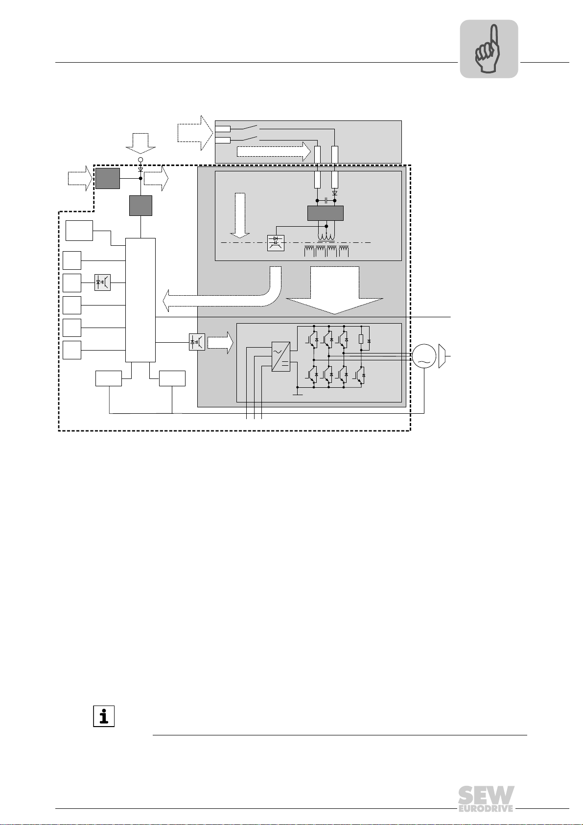
4.2.2 Schematic representation of the safety concept using the example of MOVIDRIVE® B
4
[1] High voltage switched-mode power supply
[2] Low voltage switched-mode power supply
[3] Safety relay (external) approved for at least category 3 according to EN 954-1
[4] Safety-oriented 24 V voltage supply
[5] Safety switched-mode power supply (SNT)
[6] Electrical isolation
[7] Safety circuit
[8] Feedback to the processor core: Voltage supply for output stage control OK (not in safety circuit)
[9] Voltage supply for control of power transistors
[10] DC 24 V safety switched-mode power supply disconnected / brake applied (not in safety circuit)
[11] Motor
[12] Power section
[13] Temperature detection
[14] Position detection
[15] Pulse width modulated signals for the output stage
[16] Computer core
[17] Fieldbus connection
INFORMATION
This basic representation also applies to MOVITRAC®B.
61519AXX
Manual – DFS21B Fieldbus Interface PROFINET IO with PROFIsafe (Safe Stop)
13
Page 14

5
Phone: 800.894.0412 - Fax: 888.723.4773 - Web: www.clrwtr.com - Email: info@clrwtr.com
Safety Conditions
Installation requirements
5 Safety Conditions
INFORMATION
For information on the safety-relevant conditions, refer to the following documents:
•"MOVIDRIVE
• "MOVITRAC
5.1 Installation requirements
5.1.1 F-DO connection
®
MDX60B/61B Safe Disconnection – Conditions" manual
®
B Safe Disconnection – Conditions" manual
• Only connect cables with a core cross section of a minimum of 0.25 mm
up to a maximum 1 mm
X31:2) of the DFS21B option. Clamping without conductor end sleeves is possible in
accordance with IEC 60999.
• The maximum current load of the F-DO safety-related binary output is DC 1 A.
• The safety-related binary output is 2-pole, designed as P-M switch, and controlled
via PROFIsafe
• An actuator must generally be connected with the safe output F-DO with a 2-pole
connection between the P switch output and the M switch output (F-DO_P and
F-DO_M).
• It is not permitted to make a 1-pole connection between F-DO_P and the GND reference potential as doing so would cause an error as soon as the output is controlled.
• Internal testing of the safe output is cyclical. However, when decoupling takes place,
the test pulses at the connection terminals are not visible and need not be taken into
account during operation.
5.1.2 DC 24 V voltage supply
The 24 V supply voltage(s) of the DFS21B and all stations connected to the fieldbus
must be designed as safety extra-low voltage. The voltage must lie within the limits defined in the technical data. In addition, the following voltage values must not be exceeded if a fault occurs (according to EN 60950): Max. DC 60 V, max. DC 120 V for 200 ms.
2
(AWG18) to the safety-related binary output F-DO (X31:1,
®
by a higher-level safety control.
2
(AWG23)
14
Manual – DFS21B Fieldbus Interface PROFINET IO with PROFIsafe (Safe Stop)
Page 15

Assembly and Installation Notes
Phone: 800.894.0412 - Fax: 888.723.4773 - Web: www.clrwtr.com - Email: info@clrwtr.com
Installing the DFS21B option card in MOVIDRIVE® MDX61B
6 Assembly and Installation Notes
6
This section contains information about assembly and installation of the DFS21B
PROFINET IO option card in MOVIDRIVE
gateway housing.
®
MDX61B, MOVITRAC® B and the UOH11B
6.1 Installing the DFS21B option card in MOVIDRIVE® MDX61B
INFORMATION
• Only SEW-EURODRIVE engineers are allowed to install or remove option
cards for MOVIDRIVE
• Users may only install or remove option cards for MOVIDRIVE
sizes 1 to 6.
• You have to insert the DFS21B PROFINET IO option in fieldbus slot [1].
• Only use connectors and cables approved for PROFINET IO when cabling.
[1]
®
MDX61B size 0.
®
MDX61B
Manual – DFS21B Fieldbus Interface PROFINET IO with PROFIsafe (Safe Stop)
62179AXX
15
Page 16

6
Phone: 800.894.0412 - Fax: 888.723.4773 - Web: www.clrwtr.com - Email: info@clrwtr.com
6.1.1 Before you start
Assembly and Installation Notes
Installing the DFS21B option card in MOVIDRIVE® MDX61B
Observe the following notes before installing or removing an option card:
• Disconnect the inverter from the power. Switch off the DC 24 V and the line voltage.
• Take appropriate measures to protect the option card from electrostatic charge (use
discharge strap, conductive shoes, etc.) before touching it.
• Before installing the option card, remove the keypad and the front cover
(→ MOVIDRIVE
• After installing the option card, replace the front cover and the keypad
(→ MOVIDRIVE
• Keep the option card in its original packaging until immediately before you are ready
to install it.
• Hold the option card by its edges only. Do not touch any of the components.
®
MDX60B/61B operating instructions, section 'Installation').
®
MDX60B/61B operating instructions, sec. "Installation").
16
Manual – DFS21B Fieldbus Interface PROFINET IO with PROFIsafe (Safe Stop)
Page 17
Assembly and Installation Notes
1.
4.
4.
1.
2.
3.
3.
3.
2.
Phone: 800.894.0412 - Fax: 888.723.4773 - Web: www.clrwtr.com - Email: info@clrwtr.com
Installing the DFS21B option card in MOVIDRIVE® MDX61B
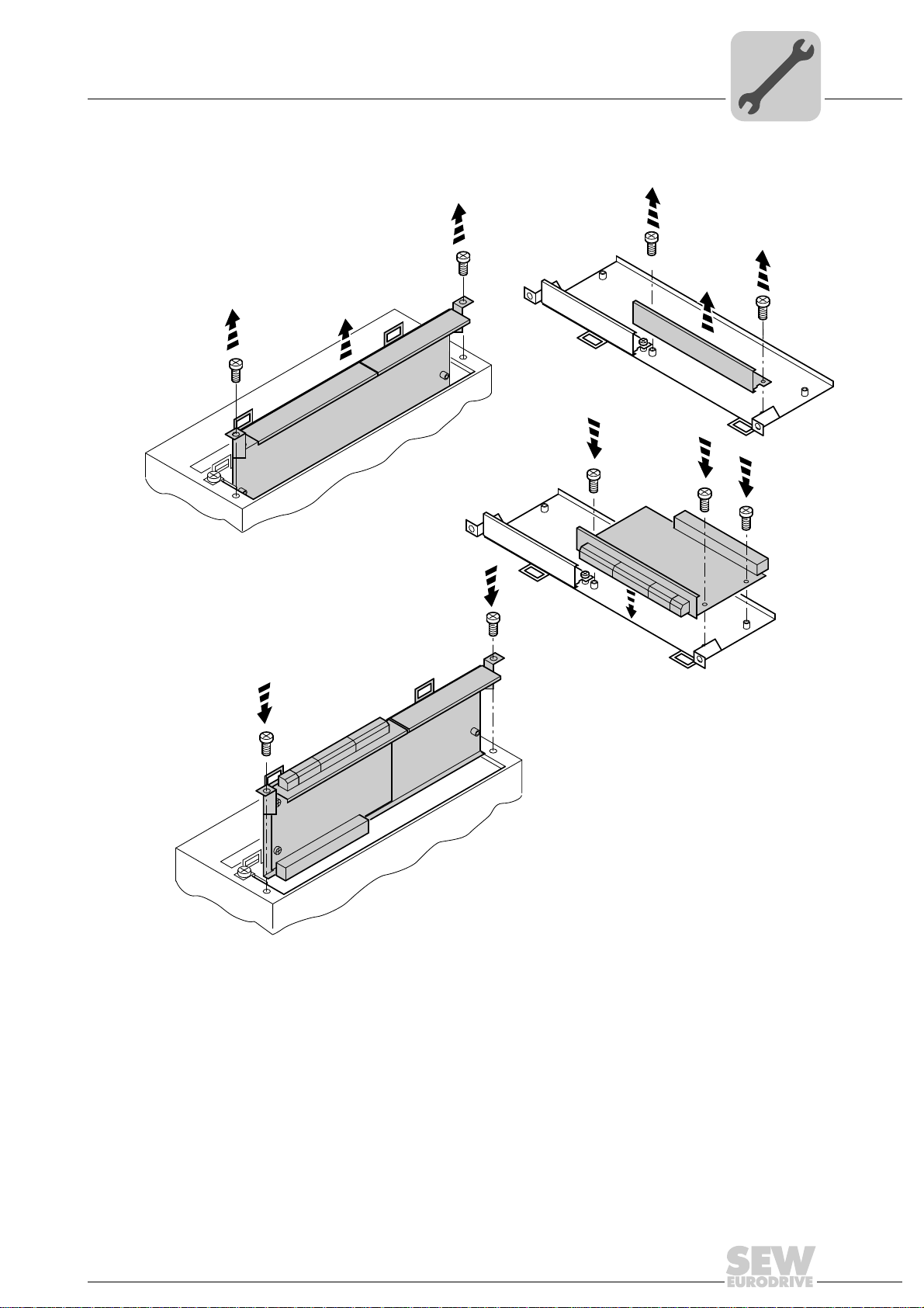
6.1.2 Basic procedure for installing and removing an option card (MDX61B, BG 1 - 6)
6
60039AXX
1. Remove the two retaining screws holding the card retaining bracket. Pull the card retaining bracket out evenly from the slot (do not twist!).
2. Remove the 2 retaining screws from the black cover plate on the card retaining
bracket. Remove the black cover plate.
3. Position the option card onto the retaining bracket so that the three retaining screws
fit into the corresponding bores on the card retaining bracket.
4. Insert the retaining bracket with the installed option card into the slot, pressing slightly so it is seated properly. Secure the card retaining bracket with the two retaining
screws.
5. To remove the option card, follow the instructions in reverse order.
Manual – DFS21B Fieldbus Interface PROFINET IO with PROFIsafe (Safe Stop)
17
Page 18

6
X45
X46
1
23456HL ⊥
FSC11B
S1
OFF
ON
7
S2
X44
X26
1234567
X24
H1
H2
X12
1
2
3
4
5
6
7
8
24V IO
DC 24 V
–
+
9
GND
=
X30X32
Def IP
PROFINET IO
AS
01
DFS21B
X31
FSR
FDOBF
12
34
56
FDO
LS
PS
01
2
2
2
2
0
1
2
3
2
2
2
4
5
6
2
7
2
8
2
9
F-ADDRESS
Phone: 800.894.0412 - Fax: 888.723.4773 - Web: www.clrwtr.com - Email: info@clrwtr.com
Assembly and Installation Notes
Installing the DFS21B option card in MOVITRAC® B
6.2 Installing the DFS21B option card in MOVITRAC® B
INFORMATION
•MOVITRAC® B does not require a special firmware status.
• Only SEW-EURODRIVE personnel may install or remove options cards for
MOVITRAC
6.2.1 Connecting a system bus (SBus 1) between MOVITRAC® B and the DFS21B option
®
B.
X46 X26 Terminal assignment
X46:1 X26:1 SC11 SBus +, CAN high
X46:2 X26:2 SC12 SBus -, CAN low
X46:3 X26:3 GND, CAN GND
X46:7 X26:7 DC 24 V
X12 Terminal assignment
X12:8 DC+24 V input
X12:9 GND reference potential for binary inputs
To simplify cabling, the DFS21B option can be supplied with DC 24 V from X46:7 of
®
B to X26:7.
®
B must be supplied with DC 24 V at terminals X12:8 and X12:9 when it
Manual – DFS21B Fieldbus Interface PROFINET IO with PROFIsafe (Safe Stop)
18
MOVITRAC
MOVITRAC
supplies the DFS21B option.
Activate the system bus terminating resistor at the FSC11B option (S1 = ON).
62409AXX
Page 19

Assembly and Installation Notes
X45
X46
1
23456HL ^
FSC11B
MOVITRAC® B
S1
OFF
ON
7
S2
X44
X45
X46
1
23456HL ^
FSC11B
MOVITRAC® B
S1
OFF
ON
7
S2
X44
X45
X46
1
23456HL^
FSC11B
MOVITRAC® B
S1
OFF
ON
7
S2
X44
X26
1234567
X24
H1
H2
X12
1
2
3
4
5
6
7
8
24V IO
DC 24 V
-
+
9
GND
=
X30X32
Def IP
PROFINET IO
AS
01
DFS21B
X31
FSR
FDOBF
12
34
56
FDO
LS
PS
01
2
2
2
2
0
1
2
3
2
2
2
4
5
6
2
7
2
8
2
9
F-ADDRESS
Phone: 800.894.0412 - Fax: 888.723.4773 - Web: www.clrwtr.com - Email: info@clrwtr.com
Installing the DFS21B option card in MOVITRAC® B
6.2.2 Connecting a system bus (SBus 1) between several MOVITRAC® B units
6
MOVITRAC® B DFS21B via UOH11B gateway housing
X46 Terminal assignment X26 Terminal assignment
X46:1 SC11 (System bus high, incoming) X26:1 SC11 SBus +, CAN High
62408AXX
X46:2 SC12 (System bus low, incoming) X26:2 SC12 SBus -, CAN Low
X46:3 GND (System bus reference) X26:3 GND, CAN GND
X46:4 SC21 (System bus high, outgoing)
X46:5 SC22 (System bus low, outgoing)
X46:6 GND (System bus reference)
X46:7 DC 24 V X26:7 DC 24 V
X12 Terminal assignment
X12:8 DC+24 V input
X12:9 GND reference potential for binary inputs
Manual – DFS21B Fieldbus Interface PROFINET IO with PROFIsafe (Safe Stop)
19
Page 20

6
Phone: 800.894.0412 - Fax: 888.723.4773 - Web: www.clrwtr.com - Email: info@clrwtr.com
Assembly and Installation Notes
Installing the DFS21B option card in MOVITRAC® B
Please note:
• Use a 2x2 core twisted pair and shielded copper cable (data transmission cable with
braided copper shield). Connect the shield flatly on both sides of the electronics
shield clamp of MOVITRAC
ble must meet the following specifications:
– Cable cross section 0.25 mm
– Line resistance 120 Ω at 1 MHz
– Capacitance per unit length ≤ 40 pF/m at 1 kHz
Suitable cables are CAN or DeviceNet cables.
• The permitted total cable length depends on the baud rate setting of the SBus:
– 250 kBaud: 160 m
– 500 kBaud: 80 m
– 1000 kBaud: 40 m
• Connect the system bus terminating resistor (S1 = ON) at the end of the system bus
connection. Switch off the terminating resistor on the other units (S1 = OFF). The
DFS21B gateway must always be connected either at the beginning or the end of the
system bus connection and feature a permanently installed terminating resistor.
®
B. Also connect the ends of the shield to GND. The ca-
2
(AWG18) ... 0.75 mm2 (AWG23)
INFORMATION
• There must not be any potential displacement between the units connected with
the SBus. Take suitable measures to avoid potential displacement, such as connecting the unit ground connectors using a separate cable.
• Point-to-point wiring is not permitted.
20
Manual – DFS21B Fieldbus Interface PROFINET IO with PROFIsafe (Safe Stop)
Page 21
Assembly and Installation Notes
X26
1
23456
7
SEW Drive
UOH11B
DC+24 V
GND
X24
H1
H2
SC11 Systembus +, CAN high
SC12 Systembus -, CAN low
GND, CAN GND
X30X32
Def IP
PROFINET IO
AS
01
DFS21B
X31
FSR
FDOBF
12
34
56
FDO
LS
PS
01
2
2
2
2
0
1
2
3
2
2
2
4
5
6
2
7
2
8
2
9
F-ADDRESS
Phone: 800.894.0412 - Fax: 888.723.4773 - Web: www.clrwtr.com - Email: info@clrwtr.com
Installing the DFS21B/UOH11B gateway
6.3 Installing the DFS21B/UOH11B gateway
The following figure shows the connection of the DFS21B option via the UOH11B:X26
gateway housing.
INFORMATION
Only SEW-EURODRIVE engineers are allowed to install or remove option cards
in/from the UOH11B gateway housing.
6
Manual – DFS21B Fieldbus Interface PROFINET IO with PROFIsafe (Safe Stop)
UOH11B gateway housing
X26 Terminal assignment
X26:1 SC11 System bus +, CAN high
X26:2 SC12 system bus -, CAN low
X26:3 GND, CAN GND
X26:4 Reserved
X26:5 Reserved
X26:6 GND, CAN GND
X26:7 DC 24 V
The gateway housing is powered with DC 24 V at X26.
Connect the system bus terminating resistor at the end of the system bus connection.
62407AXX
21
Page 22
6
Phone: 800.894.0412 - Fax: 888.723.4773 - Web: www.clrwtr.com - Email: info@clrwtr.com
Assembly and Installation Notes
Connection and terminal description DFS21B option
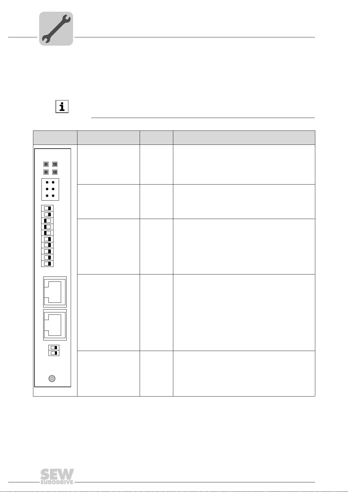
6.4 Connection and terminal description DFS21B option
Part number PROFINET IO fieldbus interface option, type DFS21B: 1821 183 6
INFORMATION
• The "DFS21B PROFINET IO fieldbus interface " option is only possible in conjunction with MOVIDRIVE
• Plug the DFS21B option into the fieldbus slot.
®
MDX61B, not with MDX60B.
Front view of
DFS11B
DFS21B
FSR
FDOBF
2
2
2
2
2
2
2
2
2
2
FDO
LS
PS
0
1
2
3
4
5
6
7
8
9
12
34
X31
56
F-ADDRESS
01
X30X32
Description
Diagnostic LEDs: R
X31 connection 1 (F_DO_M)
F-ADDRESS: DIP switch
for setting the failsafe
address
X30: Ethernet connection
LED Link (green)
LED Activity (yellow)
DIP switch
Terminal
FS
MP
FDO
2 (F_DO_P)
3 (GND)
4 (24 V_LS)
5 (GND)
6 (24 V_PS)
0
2
1
2
2
2
3
2
4
2
5
2
6
2
7
2
8
2
9
2
Function
RUN - Component status (green)
Failsafe status - Status of the safety option (green during standard
operation)
BUS FAULT - Bus status (red if a fault occurs, else disabled)
Failsafe output - Status of the safe output (orange)
Safe output
Safe output
Supply of the safe output
Supply of the safe output
Power supply to control electronics
Power supply to control electronics
Significance: 1
Significance: 2
Significance: 4
Significance: 8
Significance: 16
Significance: 32
Significance: 64
Significance: 128
Significance: 256
Significance: 512
1)
1)
X32: Ethernet connection
LED Link (green)
LED Activity (yellow)
Def IP
AS
01
PROFINET IO
62396AXX
1) The 24 V supply voltage(s) of the DFS21B and all stations connected to the fieldbus must be designed as safety extra-low voltage.
The voltage must lie within the limits defined in the technical data. In addition, the following voltage values must not be exceeded if a
fault occurs (according to EN 60950): Max. DC 60 V, max. DC 120 V for 200 ms.
22
DIP switch AS
DEF IP
Manual – DFS21B Fieldbus Interface PROFINET IO with PROFIsafe (Safe Stop)
Auto-setup for gateway operation
Resets the address parameters to the following default values:
• IP address: 192.168.10.4
• Subnet mask: 255.255.255.0
• Gateway: 1.0.0.0
• PROFINET device name: PNETDeviceName_MACID
Page 23
Assembly and Installation Notes
X24
H1
H2
Phone: 800.894.0412 - Fax: 888.723.4773 - Web: www.clrwtr.com - Email: info@clrwtr.com
Wiring diagrams for safe technology
6
Front view of
MOVITRAC
®
B,
Description Function
DFS21B and UOH11B
LED H1 (red)
LED H2 (green)
X24 X terminal
System bus error (only for gateway functions)
Reserved
RS485 interface for diagnostics via PC and MOVITOOLS
MotionStudio (only for MOVITRAC
58129axx
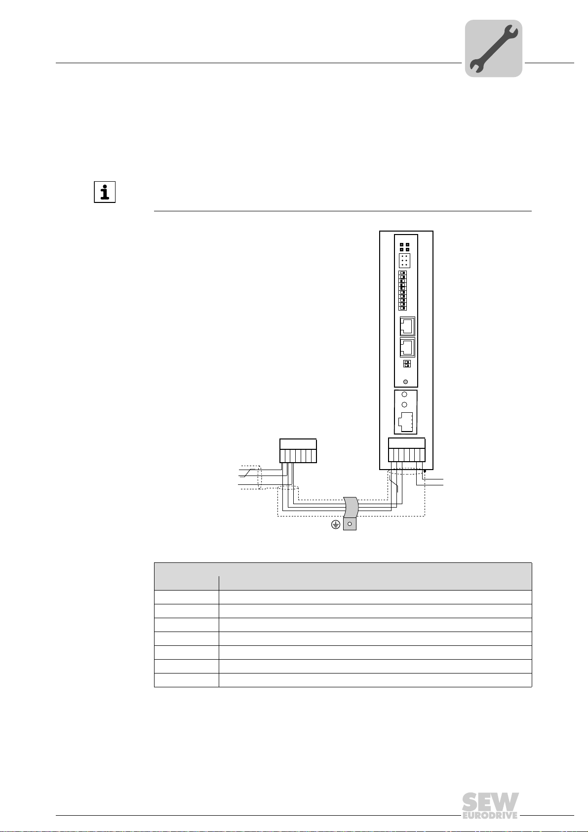
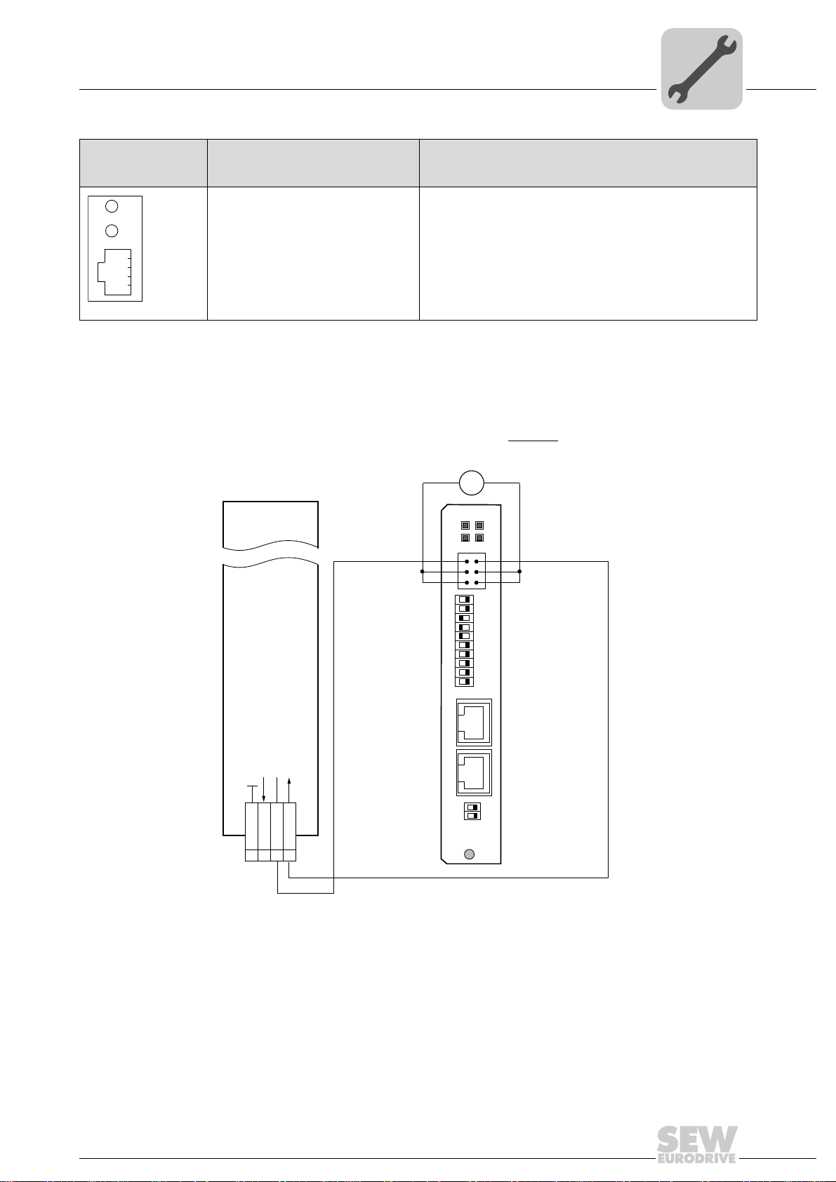
6.5 Wiring diagrams for safe technology
6.5.1 Individual wiring of MOVIDRIVE® MDX60B/61B and MOVITRAC® B
Voltage
supply
24V
MOVIDRIVE® B
MOVITRAC
®
B
X31:1 - F-DO_M
–
DFS21B
12
GND
34
56
F-ADDRESS
01
+
=
FSR
FDOBF
X31
2
2
2
2
2
2
2
2
2
2
FDOFDO
LS
PSGND
0
1
2
3
4
5
6
7
8
9
X31:2 - F_DO_P
[1]
®
®
B)
Cable
specification
X30X32
Binary signal reference potential
Reference DC +24 V input safe stop
DC +24 V input safe stop
DC +24 V output
Def IP
AS
01
PROFINET IO
62410AEN
X17:
VO24
1 DGND
234
SVI24
SOV24
[1] The 24 V supply voltage(s) of the DFS21B and all stations connected to the fieldbus must be
designed as safety extra-low voltage. The voltage must lie within the limits defined in the technical
data. In addition, the following voltage values must not be exceeded if a fault occurs (according to
EN 60950): Max. DC 60 V, max. DC 120 V for 200 ms.
2
Only connect cables with a core cross section of a minimum of 0.25 mm
2
to a maximum 1 mm
(AWG18) to the safety-related binary output F-DO (X31:1, X31:2)
(AWG23) up
of the DFS21B option. Clamping without conductor end sleeves is possible in accordance with IEC 60999. The maximum line length is 30 m.
Manual – DFS21B Fieldbus Interface PROFINET IO with PROFIsafe (Safe Stop)
23
Page 24

6
Phone: 800.894.0412 - Fax: 888.723.4773 - Web: www.clrwtr.com - Email: info@clrwtr.com
Assembly and Installation Notes
Wiring diagrams for safe technology
F-DO connection • The safety-related binary output F-DO is 2-pole, designed as P-M switch, and con-
trolled via PROFIsafe
• An actuator must generally be connected with the safe output F-DO with a 2-pole
connection between the P switch output and the M switch output (F-DO_P and
F-DO_M).
• It is not permitted to make a 1-pole connection between F-DO_P and the GND reference potential as doing so would cause an error as soon as the output is controlled.
• Internal testing of the safe output is cyclical. However, when decoupling takes place,
the test pulses at the connection terminals are not visible and need not be taken into
account during operation.
Internal tests and monitoring processes are able to detect various external faults:
When the output is switched on, the following faults can be detected:
• Short circuit between P output and reference potential
• Short circuit between M output and DC +24 V supply voltage
• Short circuit between P output and M output
When the output is switched off, the following faults can be detected:
• Short circuit between P output and reference potential
• Short circuit between M output and reference potential
• Short circuit between P output and DC +24 V supply voltage
• Short circuit between M output and DC +24 V supply voltage
®
by a higher-level safety controller.
Whenever the system detects a fault, it reverts to a safe status, i.e. all safety-related process values (F-DO) are set to "0". In addition, the safety component is passivated. The
fault is indicated by the "FS" LED (failsafe status) (→ page 34).
The 24 V supply voltage(s) of the DFS21B and all stations connected to the fieldbus
must be designed as safety extra-low voltage. The voltage must lie within the limits defined in the technical data. In addition, the following voltage values must not be exceeded if a fault occurs (according to EN 60950): Max. DC 60 V, max. DC 120 V for 200 ms.
24
Manual – DFS21B Fieldbus Interface PROFINET IO with PROFIsafe (Safe Stop)
Page 25
Assembly and Installation Notes
1 DGND
X17:
Binary signal reference potential
Reference DC +24 V input safe stop
DC +24 V input safe stop
DC +24 V output
VO24
SOV24
SVI24
234
MOVIDRIVE® B
MOVITRAC
®
B
1 DGND
X17:
Binary signal reference potential
Reference DC +24 V input safe stop
DC +24 V input safe stop
DC +24 V output
VO24
SOV24
SVI24
234
MOVIDRIVE® B
MOVITRAC
®
B
1 DGND
X17:
Binary signal reference potential
Reference DC +24 V input safe stop
DC +24 V input safe stop
DC +24 V output
VO24
SOV24
SVI24
234
MOVIDRIVE® B
MOVITRAC
®
B
DFS21B
01
2
2
2
2
0
1
2
3
2
2
2
4
5
6
2
7
2
8
2
9
F-ADDRESS
X31
FSR
FDOBF
12
34
56
FDOFDO
LS
PSGND
GND
24V
–
+
=
X31:1 - F-DO_M X31:2 - F_DO_P
Voltage
supply
[1]
X30X32
Def IP
PROFINET IO
AS
01
Phone: 800.894.0412 - Fax: 888.723.4773 - Web: www.clrwtr.com - Email: info@clrwtr.com
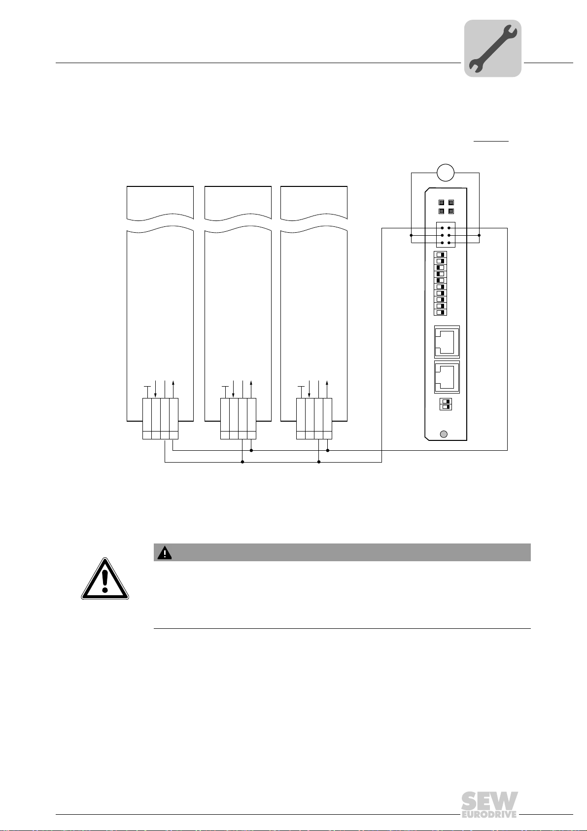
Wiring diagrams for safe technology
6.5.2 Group wiring of MOVIDRIVE® MDX60B/61B and MOVITRAC® B
6
[1] The 24 V supply voltage(s) of the DFS21B and all stations connected to the fieldbus must be
designed as safety extra-low voltage. The voltage must lie within the limits defined in the technical
data. In addition, the following voltage values must not be exceeded if a fault occurs (according to
EN 60950): Max. DC 60 V, max. DC 120 V for 200 ms.
WARNING
Observe that the maximum current load of the F-DO safety-related binary output is
DC 1 A.
The DFS21B option card might be destroyed if the maximum current load (DC 1 A) of
the safety-related binary output F-DO is exceeded. In this case, the safety function of
MOVIDRIVE
®
B / MOVITRAC® B is not ensured.
62411AEN
Manual – DFS21B Fieldbus Interface PROFINET IO with PROFIsafe (Safe Stop)
25
Page 26

6
Phone: 800.894.0412 - Fax: 888.723.4773 - Web: www.clrwtr.com - Email: info@clrwtr.com
Assembly and Installation Notes
Wiring diagrams for safe technology
Cable
specification
Only connect cables with a core cross section of a minimum of 0.25 mm2 (AWG23) up
2
to a maximum 1 mm
(AWG18) to the safety-related binary output F-DO (X31:1, X31:2)
of the DFS21B option. Clamping without conductor end sleeves is possible in accordance with IEC 60999.
Power consumption X17:4
Size MOVIDRIVE® B MOVITRAC® B
03 W
15 W
2, 2S 6 W
3 7.5 W
48 W
5 10 W
66 W -
26
Manual – DFS21B Fieldbus Interface PROFINET IO with PROFIsafe (Safe Stop)
Page 27
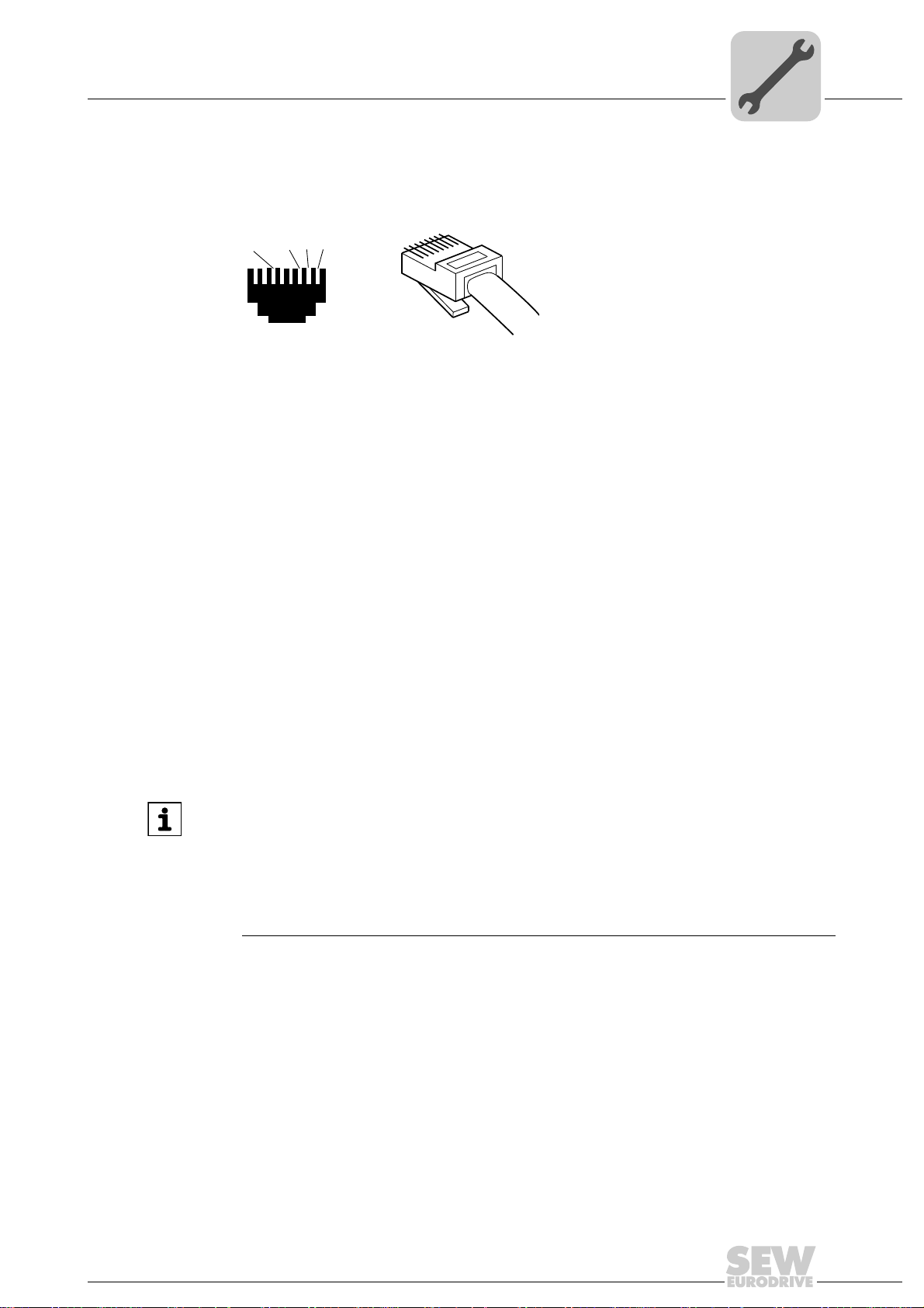
6.6 Pin assignment
[3]
[2]
[1]
2
3
6
1
[6]
AB
Phone: 800.894.0412 - Fax: 888.723.4773 - Web: www.clrwtr.com - Email: info@clrwtr.com
Use prefabricated, shielded RJ45 plug connectors compliant with IEC 11801 edition 2.0,
category 5.
Assembly and Installation Notes
Pin assignment
6
Figure 1: Pin assignment of an RJ45 plug connector
A = Front view
B = View from back
[1] Pin 1 TX+ Transmit Plus
[2] Pin 2 TX- Transmit Minus
[3] Pin 3 RX+ Receive Plus
[6] Pin 6 RX- Receive Minus
Connection between MOVIDRIVE
To connect the DFS21B, connect the Ethernet interface X30 or X32 (RJ45 connector)
using a category 5, class D shielded twisted-pair cable in compliance with IEC 11801
edition 2.0. The integrated switch provides support for realizing a line topology.
INFORMATION
• According to IEC 802.3, the maximum cable length for 10 / 100 Mbaud Ethernet
(10BaseT/100BaseT), e.g. between DFS21B and switch, is 100 m.
• VLAN tag prioritized Ethernet frames with the frame identification 8892
for the real-time data exchange with PROFINET IO. This requires switched networks. The switches must support prioritization. Hubs are not permitted. Data
transmission takes place using the full duplex process with 100 Mbit. Detailed information on cabling can be found in the 'PROFINET installation guideline' publication that was issued by the PROFINET user organization.
®
B / MOVITRAC® B / Ethernet
are used
hex
54174AXX
Manual – DFS21B Fieldbus Interface PROFINET IO with PROFIsafe (Safe Stop)
27
Page 28

6
Phone: 800.894.0412 - Fax: 888.723.4773 - Web: www.clrwtr.com - Email: info@clrwtr.com
Assembly and Installation Notes
Shielding and routing bus cables
6.7 Shielding and routing bus cables
Only use shielded cables and connection elements that meet the requirements of category 5, class D according to IEC 11801 edition 2.0.
Correct shielding of the bus cable attenuates electrical interference that can occur in industrial environments. The following measures ensure the best possible shielding:
• Manually tighten the mounting screws on the connectors, modules, and equipotential
bonding conductors.
• Use only connectors with a metal housing or a metalized housing.
• Connect the shielding in the connector over a wide surface area.
• Apply the shielding of the bus cable on both ends.
• Route signal and bus cables in separate cable ducts. Do not route them parallel to
power cables (motor leads).
• Use metallic, grounded cable racks in industrial environments.
• Route the signal cable and the corresponding equipotential bonding close to each
other using the shortest possible route.
• Avoid using plug connectors to extend bus cables.
• Route the bus cables closely along existing grounding surfaces.
WARNING
In case of fluctuations in the ground potential, a compensating current may flow via the
bilaterally connected shield that is also connected to the protective earth (PE). Make
sure you supply adequate equipotential bonding in accordance with relevant VDE regulations in such a case.
28
Manual – DFS21B Fieldbus Interface PROFINET IO with PROFIsafe (Safe Stop)
Page 29
Assembly and Installation Notes
Phone: 800.894.0412 - Fax: 888.723.4773 - Web: www.clrwtr.com - Email: info@clrwtr.com
TCP/IP addressing and subnetworks
6.8 TCP/IP addressing and subnetworks
Introduction The settings for the address of the IP protocol are made using the following parameters:
• IP address
• Subnet mask
• Standard gateway
The addressing mechanisms and subdivision of the IP networks into subnets are explained in this chapter to help you set the parameters correctly.
IP address The IP address is a 32-bit value that uniquely identifies a node in the network. An IP ad-
dress is represented by four decimal numbers separated by decimal points.
Example: 192.168.10.4
Each decimal number stands for one byte (= 8 bits) of the address and can also be rep-
resented using binary code (→ following table).
Byte 1 Byte 2 Byte 3 Byte 4
11000000 . 10101000 . 00001010 . 00000100
6
The IP address comprises a network address and a node address (→ following table).
Network address Node address
192.168.10 4
The part of the IP address that denotes the network and the part that identifies the node
is determined by the network class and the subnet mask.
Node addresses cannot consist of only zeros or ones (binary) because they represent
the network itself or a broadcast address.
Network classes The first byte of the IP address determines the network class and as such represents
the division into network addresses and node addresses.
Value range
Byte 1
0 ... 127 A 10.1.22.3 10 = Network address
128 ... 191 B 172.16.52.4 172.16 = Network address
192 ... 223 C 192.168.10.4 192.168.10 = Network address
Network class
Complete network address
(Example)
Meaning
1.22.3 = node address
52.4 = node address
4 = node address
This rough division is not sufficient for a number of networks. They also use an explicit,
adjustable subnet mask.
Subnet mask A subnet mask is used to divide the network classes into even finer sections. Like the
IP address, the subnetwork mask is represented by four decimal numbers separated by
decimal points. Every decimal number stands for one byte.
Example: 255.255.255.128
Each decimal number stands for one byte (= 8 bits) of the subnet mask and can also be
represented using binary code (→ following table).
Byte 1 Byte 2 Byte 3 Byte 4
11111111 . 11111111 . 11111111 . 10000000
Manual – DFS21B Fieldbus Interface PROFINET IO with PROFIsafe (Safe Stop)
29
Page 30

6
Phone: 800.894.0412 - Fax: 888.723.4773 - Web: www.clrwtr.com - Email: info@clrwtr.com
Assembly and Installation Notes
TCP/IP addressing and subnetworks
If you compare the IP addresses with the subnetwork masks, you see that in the binary
representation of the subnetwork mask all ones determine the network address and all
the zeros determine the station address (→ following table).
Byte 1 Byte 2 Byte 3 Byte 4
IP address
Subnet mask
The class C network with the address 192.168.10. is further subdivided into
255.255.255.128 using the subnet mask. Two networks are created with the address
192.168.10.0 and 192.168.10.128.
The following node addresses are permitted in the two networks:
• 192.168.10.1 ... 192.168.10.126
• 192.168.10.129 ... 192.168.10.254
The network nodes use a logical AND operation for the IP address and the subnet mask
to determine whether there is a communication partner in the same network or in a different network. If the communication partner is in a different network, the standard gateway is addressed.
decimal 192 . 168. . 10 . 128
binary 11000000 . 10101000 . 00001010 . 10000000
decimal 255 . 255 . 255 . 128
binary 11111111 . 11111111 . 11111111 . 10000000
Standard gateway The standard gateway is also addressed via a 32-bit address. The 32-bit address is rep-
resented by four decimal numbers separated by decimal points.
Example: 192.168.10.1
The standard gateway establishes a connection to other networks. In this way, a net-
work node that wants to address another node can use a logical AND operation with the
IP address and the subnetwork mask to decide whether the desired node is located in
the same network. If this is not the case, the node addresses the standard gateway
(router), which must be part of the actual network. The standard gateway then takes on
the job of transmitting the data packages.
30
Manual – DFS21B Fieldbus Interface PROFINET IO with PROFIsafe (Safe Stop)
Page 31

Assembly and Installation Notes
Phone: 800.894.0412 - Fax: 888.723.4773 - Web: www.clrwtr.com - Email: info@clrwtr.com
Setting the IP address parameters via DCP
6.9 Setting the IP address parameters via DCP
Initial startup For PROFINET IO, the IP address parameters are determined via the "DCP" protocol
(Discovery and Configuration Protocol). DCP operates with device names. The device
name uniquely identifies a PROFINET IO node in the network. It is identified with the
PROFINET IO controller during the configuration of the node and also set using the configuration software on the PROFINET IO device. With the aid of the device name, the
controller identifies the device during startup and transfers the corresponding IP address
parameters. Settings directly on the slave are no longer required. The basic procedure
is described with SIMATIC STEP 7 as an example in chapter "Configuration with
PROFINET" (→ section "Assigning the PROFINET device name").
6
Resetting the IP
address
parameters
If you do not know the IP address parameters and cannot access the inverter using the
serial interface or the DBG60B keypad, you can reset the IP address parameters to the
default values using the DIP switch 'Def IP'.
This action resets the DFS21B option to the following default values:
• IP address: 192.168.10.4
• Subnet mask: 255.255.255.0
• Default gateway: 1.0.0.0
• PROFINET device name: PNETDeviceName
Proceed as follows to reset the IP address parameters to the default values:
• Switch off the 24 V DC supply voltage and the mains voltage.
• Set the DIP switch "Def IP" on the DFS21B option to "1."
• Switch the DC 24 V supply voltage and the line voltage back on.
• Wait until the DFS21B option has booted up. The "RUN" LED is green when the option is ready.
You can now access the inverter via the IP address 192.168.10.4. Proceed as follows
to set new IP address parameters:
• Start a web browser and access the homepage of the DFS21B option or start
MOVITOOLS
• Select the required address parameters.
• Set the DIP switch "Def IP" on the DFE32B option to "0."
• The new address parameters are adopted after the device is switched off and
switched on again.
®
MotionStudio.
Manual – DFS21B Fieldbus Interface PROFINET IO with PROFIsafe (Safe Stop)
31
Page 32

6
Phone: 800.894.0412 - Fax: 888.723.4773 - Web: www.clrwtr.com - Email: info@clrwtr.com
Assembly and Installation Notes
Procedure after a unit replacement
6.10 Procedure after a unit replacement
6.10.1 MOVIDRIVE® B unit replacement
6.10.2 MOVITRAC
If you insert the memory card of the replaced MOVIDRIVE
®
B in the new MOVIDRIVE
B, the new unit is recognized by the PROFINET IO controller without any additional
measures.
INFORMATION
If you do not install the memory card of the replaced MOVIDRIVE
MOVIDRIVE
to load the saved parameter set into the new MOVIDRIVE
®
B, you have to perform a complete startup of the inverter or you have
®
B. Further, you have to set
the PROFINET IO unit name again using the configuration software. Proceed as with
an initial startup (→ section "Configuration with PROFINET").
If you only replace the DFS21B option, you have to set the PROFIsafe address of the
new option card again using the "F-ADDRESS" DIP switches. Make sure that the set
address corresponds to the PROFIsafe address in STEP7 HWCONFIG.
®
B / gateway unit replacement
• Only for device replacement MOVITRAC
the saved parameter set into the new MOVITRAC
plete startup of the inverter (→ MOVITRAC
®
B with fieldbus option: You have to load
®
®
B, or you have to perform a com-
B operating instructions).
• You have to set the PROFINET IO unit name again using the configuration software.
Proceed as with an initial startup (→ section "Configuration with PROFINET").
• Prior to the auto setup, check the parameters P884 SBus Baud Rate and P831
Fieldbus Timeout response. The baud rate of the units connected to the SBus has to
correspond to the baud rate of the gateway (DFS21B). Use the parameter tree of the
gateway in MOVITOOLS
®
MotionStudio.
• Now activate the auto setup function. Set the DIP switch "AS" on the DFS21B option
to "1".
• Use the "FADDRESS" DIP switches to set the PROFIsafe address of the new option
card. Make sure that the set address corresponds to the PROFIsafe address in
STEP7 HWCONFIG.
®
B in the new
®
32
Manual – DFS21B Fieldbus Interface PROFINET IO with PROFIsafe (Safe Stop)
Page 33

Assembly and Installation Notes
Phone: 800.894.0412 - Fax: 888.723.4773 - Web: www.clrwtr.com - Email: info@clrwtr.com
Operating displays of the DFS21B option
6.11 Operating displays of the DFS21B option
6.11.1 PROFINET LEDs
There are 4 LEDs on the DFS21B option card that display the current status of the
DFS21B option and the PROFINET system.
DFS21B
FSR
FDOBF
R LED The "R" LED (RUN) indicates that the bus electronics are operating correctly.
6
62397AXX
Status of
the "R" LED
Green •DFS21B hardware OK.
Off • DFS21B is not ready for operation.
Red • Error in the DFS21B hardware
Flashing
green
Flashing
yellow
Yellow • Switch the unit on again. Consult
Cause of error Remedy
• Functions properly
• Hardware of the DFS21B does not boot.
-
• Switch the unit on again. Consult
SEW Service if the error reoccurs.
• Switch the unit on again. Set default
IP address parameter via "DEF IP"
DIP switch. Consult SEW Service if
the error reoccurs.
SEW Service if the error reoccurs.
BF LED The "BF" LED (BUS FAULT) displays the status of the PROFINET.
Status of the
"BF" LED
Off • PROFINET IO device is currently
Flashing green
Flashing green /
red
Red • Connection to the PROFINET IO con-
Yellow
Flashing yellow
Cause of error Remedy
exchanging data with the PROFINET
master (data exchange).
• The flashing function in the PROFINET IO controller configuration is activated to visually localize the stations.
troller has failed.
• PROFINET IO device does not detect
a link
• Bus interruption
• PROFINET IO controller is not in
operation
• The STEP 7 hardware configuration
contains a module that is not permitted.
-
-
• Check the PROFINET connection of
the DFS21B option
• Check the PROFINET IO controller
• Check the cabling of your PROFINET
network
• Switch the STEP 7 hardware configuration to ONLINE and analyze the
component status of the slots in the
PROFINET IO device.
Manual – DFS21B Fieldbus Interface PROFINET IO with PROFIsafe (Safe Stop)
33
Page 34

6
Phone: 800.894.0412 - Fax: 888.723.4773 - Web: www.clrwtr.com - Email: info@clrwtr.com
Assembly and Installation Notes
Operating displays of the DFS21B option
FS LED The "FS" LED (FAILSAFE STATUS) indicates the failsafe status on PROFINET.
Status of
the "FS"
LED
Green • The DFS21B option is currently per-
Red • Fault status in the safety part.
Off • The DFS21B option is currently in the
Flashing
red / green
Cause of error Remedy
forming a cyclical data exchange with
the F-host (data exchange).
• Standard operating state.
• No 24 V_LS supply voltage present.
initialization phase.
A fault occurred in the safety part; cause
of the fault already remedied acknowledgement required.
-
• Read diagnostics in F-Host.
• Eliminate the cause of the fault and
acknowledge in the F-Host.
• Check voltage supply.
• Check configuration of the bus master.
Acknowledge fault in the F-Host (reintegration).
FDO LED The "FDO" LED (FAILSAFE OUTPUT) indicates the failsafe output on PROFINET.
Status of
the "FDO"
LED
Orange Output F-DO active
Off Output F-DO inactive (switched off)
Status
WARNING
The LEDs "R", "BF", "FDO" and "FS" are not safety-oriented and may not be used as
a safety device.
34
Manual – DFS21B Fieldbus Interface PROFINET IO with PROFIsafe (Safe Stop)
Page 35

Assembly and Installation Notes
X24
H1
H2
Phone: 800.894.0412 - Fax: 888.723.4773 - Web: www.clrwtr.com - Email: info@clrwtr.com
Operating displays of the DFS21B option
Link/Activity LED The two LEDs Link (green) and Activity (yellow), integrated in the RJ45 plug connec-
tors (X30, X32), display the status of the Ethernet connection.
6
LED "Link"
LED "Activity"
LED / Status Meaning
Link / Green There is an Ethernet connection.
Link / Off There is no Ethernet connection.
Activity / Yel-
low
X30
X32
61880AXX
Data is currently being exchanged via Ethernet.
INFORMATION
• As the firmware of the DFS21B option card requires approximately 10 seconds for
initialization, the status "0" (inverter not ready) is displayed in the 7-segment display of MOVIDRIVE
• The "R" LED on the DFS21B option card lights up green.
®
during this time.
6.11.2 Gateway LED
LEDs H1 and H2 indicate the communication status in gateway operation.
58129AXX
LED H1 Sys-Fault (red) Only for gateway function
Status Condition Description
Red System fault Gateway is not configured or one of the
drives is inactive
Off SBus ok Gateway is configured correctly
Flashing Bus scan Bus is being checked by the gateway
INFORMATION
•LED H2 (green) is currently reserved.
• X terminal X24 is the RS485 interface for diagnostics via PC and MOVITOOLS
MotionStudio.
®
Manual – DFS21B Fieldbus Interface PROFINET IO with PROFIsafe (Safe Stop)
35
Page 36

7
Phone: 800.894.0412 - Fax: 888.723.4773 - Web: www.clrwtr.com - Email: info@clrwtr.com
Configuration with PROFINET
Configuration of the PROFINET IO controller
7 Configuration with PROFINET
This chapter describes the configuration of the MOVIDRIVE® B and MOVITRAC® B /
gateway inverters with DFS21B option. The following GSD file is used for the configuration of the DFS21B with MOVIDRIVE
GSDML-V2.1-SEW-DFE-DFS-2Ports-yyyymmdd.xml
This GSD file contains the unit description for the operation of the DFS21B in
MOVIDRIVE
7.1 Configuration of the PROFINET IO controller
This section describes the configuration of MOVIDRIVE® B or MOVITRAC® B with
PROFINET using the current GSD(ML) file. The configuration is described using the example of the SIMATIC Manager configuration software with a SIMATIC CPU 315F 2
PN/DP.
®
B or as fieldbus gateway for MOVITRAC® B.
®
B or in MOVITRAC® B:
Installing the
GSD file
• Start STEP7 HWCONFIG and select the [Install new GSD file] menu item in the
[Extras] menu.
• Select the file "GSDML-V2.1-SEW-DFE-DFS-2Ports-YYYYMMDD.xml" on the "Software ROM 7" CD in the following dialog. "JJJJMMTT" [YYYYMMDD] represents the
date of the file. You can navigate to the required directory using the 'Browse' button.
Confirm your selection with [OK].
• You will find the SEW PROFINET IO DFS21B interface under [Other field devices] /
[Drives] / [SEW] / [DFE/DFS(2Ports)].
INFORMATION
The latest GSD file version is also available for download on the SEW website
in the "Software" section.
36
Manual – DFS21B Fieldbus Interface PROFINET IO with PROFIsafe (Safe Stop)
Page 37

Configuration of the PROFINET IO controller
[1]
[2]
[3] [4]
Phone: 800.894.0412 - Fax: 888.723.4773 - Web: www.clrwtr.com - Email: info@clrwtr.com
7.1.1 Assigning the PROFINET unit name
The general procedure is described using SIMATIC STEP 7 as an example.
• In STEP 7 HWCONFIG, select [PLC] / [Ethernet] / [Edit Ethernet Node ...].
• Click on "Browse". You receive an overview of all PROFINET IO nodes that you can
reach online with your configuration tool (→ following figure).
Configuration with PROFINET
7
11727AEN
• Choose the required node. The SEW node appears as "SEW-MDX61B+DFS21B"
under Device type [3]. The device name [4] is set to 'PNETDeviceName' at the factory and must be adapted to your system conditions. Several MDX61B units can be
distinguished between by the MAC addresses [2] displayed. A label with the MAC address [2] is attached to the DFS21B option. Use the [Flash] button [1] to enable the
Status LED to flash green for the selected DFS21B in order to check your selection.
Manual – DFS21B Fieldbus Interface PROFINET IO with PROFIsafe (Safe Stop)
62340AEN
37
Page 38

7
[6]
[2]
[3]
[1]
[8]
[9]
[5]
[4]
[7]
Phone: 800.894.0412 - Fax: 888.723.4773 - Web: www.clrwtr.com - Email: info@clrwtr.com
Configuration with PROFINET
Configuration of the PROFINET IO controller
62330AEN
[1] 'Close' button
[2] "Device name" input field
[3] "Assign IP Configuration" button
[4] "Subnet mask" input field
[5] "IP address" edit box
[6] "Browse" button
[7] "Router address" input field
[8] "Assign name" button
[9] "Reset" button
• Enter the device name in the "Device name" input field [2] and click the [Assign
name] button [8]. The device name is now transferred to the node and saved there.
It can be up to 255 characters long.
• Specify an IP address [5] and a subnet mask [4] as well as a router address [7] if required. Click the [Assign IP Configuration] button [3].
38
Manual – DFS21B Fieldbus Interface PROFINET IO with PROFIsafe (Safe Stop)
Page 39

Configuration with PROFINET
[1]
[2]
V1.2
V1.2
V1.2
V1.2
V1.2
Phone: 800.894.0412 - Fax: 888.723.4773 - Web: www.clrwtr.com - Email: info@clrwtr.com
Configuration of the PROFINET IO controller
INFORMATION
The IO controller must not yet be in a cyclic data transmission with the IO devices.
• Click the [Browse] button [6] again to check whether your settings were adopted.
Click the [Close] button [1].
• You can reset the device name of the DFS21B online via the [Reset] button [9]. Now
you need to restart the DFS21B.
7
7.1.2 Configuration of the PROFINET interface for MOVIDRIVE
Creating a new
project
Start the SIMATIC Manager and create a new project. Select your control type and add
the required modules. The OB82, OB86 and OB122 operation modules are particularly
useful.
The OB82 operation module makes sure that the controller does not go to 'STOP' for
so-called diagnostic alarms. The OB86 operation module indicates the failure of decentralized periphery units. The OB122 operation module is called up if the controller cannot
access data of a station of the decentralized periphery. This can occur when, for example, the DFS21B is ready for operation later than the control system.
• Start STEP7 HWCONFIG and select the PN-IO slot in the control rack.
• Add a PROFINET IO system by right-clicking the context menu with your mouse.
Specify an IP address for the PROFINET IO controller when doing this. Add a new
PROFINET subsystem using the [Ethernet] button.
• Open [PROFINET IO] / [ADDITIONAL FIELD UNITS ] / [Drives] / [SEW] /
[DFE/DFS(2Ports)] [1] in the hardware catalog.
®
B
There are several entries.
Manual – DFS21B Fieldbus Interface PROFINET IO with PROFIsafe (Safe Stop)
62534AEN
39
Page 40

7
V1.2
[1
[2
Phone: 800.894.0412 - Fax: 888.723.4773 - Web: www.clrwtr.com - Email: info@clrwtr.com
Configuration with PROFINET
Configuration of the PROFINET IO controller
• Copy the required entry to the PROFINET IO system via drag & drop:
– Select "MDX61B+DFS21B V1.2" [2] if your controller supports topology detection.
– Select "MDX61B+DFS21B V1.1 OLD" if your controller does not support topolo-
gy detection.
• Assign the name of the PROFINET node.
This name must later correspond to the PROFINET unit name specified in the
DFS21B.
• Delete the entry on slot 2 in to enable the configuration of your application. Select the
process data configuration required for your application.
• Specify the I/O and periphery addresses for the configured data widths and save
your configuration.
The slot model is used for configuration with PROFINET. Each slot is assigned to a
DFS21B communication interface.
Slot 1: PROFIsafe option [1]
Slot 2: Process data channel [2]. Number of process data, cyclically exchanged be-
tween PROFINET IO controller and PROFINET IO device.
40
• Extend your user program by data exchange with the new units.
• Process data transfer is consistent. SFC14 and SFC15 can be used to transfer process data.
Manual – DFS21B Fieldbus Interface PROFINET IO with PROFIsafe (Safe Stop)
62418AEN
Page 41

Configuration with PROFINET
Phone: 800.894.0412 - Fax: 888.723.4773 - Web: www.clrwtr.com - Email: info@clrwtr.com
Configuration of the PROFINET IO controller
7
Node
configuration
When the individual slots are configured, the new node has to be configured with further
settings. Double-click the device symbol of the new node to open the following dialog.
[2]
[1]
[4]
[3]
62417AEN
[1] "General" tab
[2] "IO Cycle" tab page
[3] "Ethernet" input field
[4] "Device name" button
• Enter the previously specified device name in the "Device name" input field [4] on the
"General" tab page [1]. Note that the name is case-sensitive.
Manual – DFS21B Fieldbus Interface PROFINET IO with PROFIsafe (Safe Stop)
41
Page 42

7
Phone: 800.894.0412 - Fax: 888.723.4773 - Web: www.clrwtr.com - Email: info@clrwtr.com
Configuration with PROFINET
Configuration of the PROFINET IO controller
• To enter the previously specified IP address (→ following figure), click the [Ethernet]
button [3] in the "Node / PN IO system" field.
11781AEN
• On the "IO Cycle" tab page [2], you can specify an update time for the node to update
its process data. The DFS21B option installed in MOVIDRIVE
mum update time of 2 ms (→ following figure).
®
B supports a mini-
11782AEN
42
Manual – DFS21B Fieldbus Interface PROFINET IO with PROFIsafe (Safe Stop)
Page 43

Configuration with PROFINET
Phone: 800.894.0412 - Fax: 888.723.4773 - Web: www.clrwtr.com - Email: info@clrwtr.com
Configuration of the PROFINET IO controller
7
Starting the
controller
Load the configuration in the SIMATIC S7 and start the module. The Error LED of the
controller should now go out.
The LEDs of the DFS21B option should have the following statuses:
• R LED: lights up green
•BF LED: off
• Link / Activity LED: Flickering
If this is not the case, check the configuration, especially the device name and the IP
address of the node.
Manual – DFS21B Fieldbus Interface PROFINET IO with PROFIsafe (Safe Stop)
43
Page 44

7
Stat us –
Wort
Ist –
position
Ist –
position
Ist –
drehzahl
Ausgangs –
strom
Ger äte –
auslastung
6 process input data
Stat us –
Wort
Ist –
position
Ist –
position
Ist –
drehzahl
Ausgangs –
strom
Ger äte –
auslastung
Stat us –
Wort
Ist –
position
Ist –
position
Status
word
Actual
position
Actual
position
Ist –
drehzahl
Ausgangs –
strom
Ger äte –
auslastung
Actual
speed
Output
–
current
Unit
utilization
De-
celeration
Beschleu-
nigung
Soll-
drehzahl
Ziel-
position
Ziel-
position
Control
Wort
6 process output data
- Be schleu-
nigung
Soll-
drehzahl
Ziel-
position
Ziel-
position
Control
Wort
Beschleu-
nigung
Soll-
drehzahl
Accelera -
tion
Setpoint
speed
Ziel-
position
T-
position
Control
Wort
Target
position
Target
position
Control
word
Outputs
Inputs
IO controller:
e.g. PLC
IO device:
e.g. drive inverter
2
2
2
2
2
Phone: 800.894.0412 - Fax: 888.723.4773 - Web: www.clrwtr.com - Email: info@clrwtr.com
Configuration with PROFINET
Configuration of the PROFINET IO controller
Configuration
example for the
process data configuration of
MOVIDRIVE
®
B
®
This example is to show the positioning of the drive via MOVIDRIVE
bus positioning" application module can be used for this purpose.
The information between PLC and inverter is exchanged via 6 process data words.
The following figure shows the corresponding PROFINET parameter settings.
B. The "Extended
62347AEN
44
Manual – DFS21B Fieldbus Interface PROFINET IO with PROFIsafe (Safe Stop)
68082AEN
Page 45

Configuration with PROFINET
Phone: 800.894.0412 - Fax: 888.723.4773 - Web: www.clrwtr.com - Email: info@clrwtr.com
Configuration of the PROFINET IO controller
7.1.3 Configuration of MOVITRAC® B or gateway with DFS21B option
7
General
information
The inverter must be given a specific PROFINET configuration by the IO controller to
define type and number of input and output data words used for the transmission. You
have the opportunity to control the drives via process data and to read and write all parameters of the fieldbus interface in an acyclic way.
The following figure describes the data exchange between the programmable controller
(IO controller), the fieldbus interface (IO device) and an inverter with process data channel.
Configuring the
process data
62258AXX
The PROFINET interface allows for different configurations for the data exchange between IO controller and IO device. The configurations are determined by the default process data width for SEW inverters of three process data words. The fieldbus interface
then distributes these process data words to the individual devices. The PROFINET interface accepts 1×3 to 8×3 process data words.
INFORMATION
3 PDs are always assigned to any SBus node.
Manual – DFS21B Fieldbus Interface PROFINET IO with PROFIsafe (Safe Stop)
45
Page 46

7
[1]
[2]
V1.2
V1.2
V1.2
V1.2
V1.2
Phone: 800.894.0412 - Fax: 888.723.4773 - Web: www.clrwtr.com - Email: info@clrwtr.com
Configuration with PROFINET
Configuration of the PROFINET IO controller
7.1.4 Configuration of the PROFINET interface for MOVITRAC® B
Creating a new
project
Start the SIMATIC Manager and create a new project. Select your control type and add
the required modules. The OB82, OB86 and OB122 operation modules are particularly
useful.
The OB82 operation module makes sure that the controller does not go to 'STOP' for
so-called diagnostic alarms. The OB86 operation module indicates the failure of decentralized periphery units. The OB122 operation module is called up if the controller cannot
access data of a station of the decentralized periphery. This can occur when, for example, the DFS21B is ready for operation later than the control system.
• Start STEP7 HWCONFIG and select the PROFINET IO slot in the control rack.
• Add a PROFINET IO system by right-clicking the context menu with your mouse.
Specify an IP address for the PROFINET IO controller when doing this. Add a new
PROFINET subsystem using the [Ethernet] button.
• Open [PROFINET IO] / [ADDITIONAL FIELD UNITS ] / [Drives] / [SEW] /
[DFE/DFS(2Ports)] [1] in the hardware catalog.
There are several entries.
• Copy the required entry to the PROFINET IO system via drag & drop:
– Select "Gateway DFS21B V1.2" [2] if your controller supports topology detection.
– Select "Gateway DFS21B V1.1 OLD" if your controller does not support topology
detection.
• Assign the name of the PROFINET node.
This name must later correspond to the PROFINET unit name specified in the
DFS21B.
• The inverters connected to the gateway are represented in PROFINET as of slot 2.
Delete the entries for the respective slots depending on the number of connected inverters (e.g. slot 2 to slot 7 for a configuration of 5 inverters).
• Move the entry "AS 1 Drive (1x3PD)" to the free slots.
• Specify the I/O and periphery addresses for the configured drives and save your configuration.
46
Manual – DFS21B Fieldbus Interface PROFINET IO with PROFIsafe (Safe Stop)
62534AEN
Page 47

Configuration with PROFINET
V1.2
Phone: 800.894.0412 - Fax: 888.723.4773 - Web: www.clrwtr.com - Email: info@clrwtr.com
Configuration of the PROFINET IO controller
The slot model is used for configuration with PROFINET. Each slot is assigned to a
DFS21B fieldbus interface. The following segmentation is used for the gateway function of the DFS21B.
68083AEN
Slot 1 is not currently not used. Slots 2 ... 9 are assigned process data channels for
connected devices and 3 process data per drive.
• Extend your user program by data exchange with the new units.
• Process data transfer is consistent. SFC14 and SFC15 can be used to transfer process data.
7
Manual – DFS21B Fieldbus Interface PROFINET IO with PROFIsafe (Safe Stop)
47
Page 48

7
Phone: 800.894.0412 - Fax: 888.723.4773 - Web: www.clrwtr.com - Email: info@clrwtr.com
Configuration with PROFINET
Configuration of the PROFINET IO controller
Node
configuration
When the individual slots are configured, the new node has to be configured with further
settings. Double-click the device symbol of the new node to open the following dialog.
[2]
[1]
[4]
[3]
62535AEN
[1] "General" tab
[2] "IO Cycle" tab page
[3] "Ethernet" button.
[4] "Device name" input field
• Enter the previously specified device name in the "Device name" input field [4] on the
"General" tab page [1]. Note that the name is case-sensitive.
48
Manual – DFS21B Fieldbus Interface PROFINET IO with PROFIsafe (Safe Stop)
Page 49

Configuration with PROFINET
Phone: 800.894.0412 - Fax: 888.723.4773 - Web: www.clrwtr.com - Email: info@clrwtr.com
Configuration of the PROFINET IO controller
• To enter the previously specified IP address (→ following figure), click the [Ethernet]
button [3] in the "Node / PN IO system" field.
7
11836AEN
• On the "IO Cycle" tab page [2], you can specify an update time for the node to update
its process data. The DFS21B option in MOVITRAC
imum update time of 4 ms (→ following figure).
®
B as a gateway supports a min-
11837AEN
Manual – DFS21B Fieldbus Interface PROFINET IO with PROFIsafe (Safe Stop)
49
Page 50

7
Phone: 800.894.0412 - Fax: 888.723.4773 - Web: www.clrwtr.com - Email: info@clrwtr.com
Configuration with PROFINET
Configuration of the PROFINET IO controller
Starting the
controller
Application
example
Load the configuration in the SIMATIC S7 and start the module. The Error LED of the
controller should now go out.
The LEDs of the DFS21B option should have the following statuses:
• R LED: lights up green
•BF LED: off
• Link / Activity LED: Flickering
If this is not the case, check the configuration, especially the device name and the IP
address of the node.
8 MOVITRAC
ample. The information between PLC and the individual inverters is exchanged via 3
process data.
®
B frequency inverters are to be operated at a variable speeds in this ex-
50
Manual – DFS21B Fieldbus Interface PROFINET IO with PROFIsafe (Safe Stop)
62260AXX
Page 51

Configuration with PROFINET
V1.2
V1.2
V1.2
V1.2
V1.2
Phone: 800.894.0412 - Fax: 888.723.4773 - Web: www.clrwtr.com - Email: info@clrwtr.com
Configuration of the PROFINET IO controller
The following figure shows the corresponding PROFINET parameterization.
7
68084AEN
Manual – DFS21B Fieldbus Interface PROFINET IO with PROFIsafe (Safe Stop)
51
Page 52

7
Phone: 800.894.0412 - Fax: 888.723.4773 - Web: www.clrwtr.com - Email: info@clrwtr.com
Configuration with PROFINET
Auto setup for gateway operation
7.2 Auto setup for gateway operation
The auto setup function enables startup of the DFS21B as gateway to be performed
without a PC. It is activated via the auto setup DIP switch (see chapter "Installing the
DFS21B/UOH11B gateway" on page 21).
INFORMATION
Switching on the Auto-setup DIP switch causes the function to be performed once.
The Auto setup DIP switch must then remain in the ON position. The function can
be reactivated by turning the DIP switch off and back on again.
As a first step, the DFS21B searches for drive inverters on the SBus below its hierarchical level. This process is indicated by the H1 LED (system bus error) flashing briefly. Different SBus addresses must be set for the drive inverters (P813). We recommend assigning the addresses beginning with address 1 in ascending order based on the arrangement of inverters in the switch cabinet. The process image on the fieldbus side is
expanded by three words for each detected drive inverter.
The H1 LED remains lit if no drive inverter was located. A total of up to eight drive inverters is taken into account. The following figure shows the process image for three drive
inverters with three words each of process output data and process input data.
Following the search, the DFS21B cyclically exchanges 3 process data words with each
connected drive inverter. The process output data are fetched from the fieldbus, divided
into blocks of three and transmitted. The drive inverters read the process input data, put
them together and send them to the fieldbus master.
The cycle time of the SBus communication is 2 ms per node at a baud rate of 500 kbit/s
without any additional engineering activities.
For an application with 8 inverters on the SBus, the cycle time of the process data update is then 8 x 2 ms = 16 ms.
INFORMATION
Perform auto setup again in the following cases, since the DFS21B stores these values once during auto setup. All devices installed at the SBus must be switched on. At
the same time, the process data assignments of the connected drive inverters may not
be changed dynamically after Auto setup.
• If you change the process data assignment of the drive inverters connected to the
DFS21B.
• If you changed the SBus address of one of the connected devices.
• If you add or remove devices.
52
Manual – DFS21B Fieldbus Interface PROFINET IO with PROFIsafe (Safe Stop)
Page 53

Configuration with PROFINET
Phone: 800.894.0412 - Fax: 888.723.4773 - Web: www.clrwtr.com - Email: info@clrwtr.com
Auto setup for gateway operation
The following illustration shows the data exchange between the PLC, the DFS21B option and the inverter.
7
IO-Controller
PROFINET
DFS
62398AXX
Manual – DFS21B Fieldbus Interface PROFINET IO with PROFIsafe (Safe Stop)
53
Page 54

7
Phone: 800.894.0412 - Fax: 888.723.4773 - Web: www.clrwtr.com - Email: info@clrwtr.com
Configuration with PROFINET
Setup of the MOVIDRIVE® MDX61B inverter
7.3 Setup of the MOVIDRIVE® MDX61B inverter
11638AEN
To control the drive inverter via PROFINET, you must first switch the drive inverter to
control signal source (P101) and setpoint source (P100) = FIELDBUS. The FIELDBUS
setting means the drive inverter parameters are set for control and setpoint entry via
PROFINET. The MOVIDRIVE
transmitted from the master programmable controller.
The parameters of the MOVIDRIVE
NET without any further settings once the PROFINET option card has been installed.
For example, all parameters can be set by the master programmable controller after
power-on.
Activation of the control signal source and setpoint source FIELDBUS is signaled to the
machine controller using the "Fieldbus mode active" bit in the status word.
For safety reasons, you must also enable the drive inverter at the terminals for control
via the fieldbus system. Therefore, you must wire and program the terminals in such a
way that the drive inverter is enabled via the input terminals. For example, the simplest
way of enabling the inverter at the terminals is to connect the DIØØ (function/CONTROLLER INHIBIT) input terminal to a DC +24 V signal and to program input terminals
DIØ1 ... DIØ3 to NO FUNCTION.
®
drive inverter then responds to the process output data
®
drive inverter can be set straight away via PROFI-
54
Manual – DFS21B Fieldbus Interface PROFINET IO with PROFIsafe (Safe Stop)
Page 55

Setup of the MOVITRAC® B inverter
Phone: 800.894.0412 - Fax: 888.723.4773 - Web: www.clrwtr.com - Email: info@clrwtr.com
7.4 Setup of the MOVITRAC® B inverter
Configuration with PROFINET
7
11736AEN
To control the frequency inverter via PROFINET, you must switch the drive inverter to
control signal source (P101) and setpoint source (P100) = SBus beforehand. The SBus
setting means the inverter parameters are set for control and setpoint entry via gateway.
The MOVITRAC
mitted from the master programmable controller.
It is necessary to set the SBus1 timeout interval (P815) to a value other than 0 ms for
the MOVITRAC
tered. We recommend a value in the range 50 to 200 ms.
Activation of the control signal source and setpoint source SBus is signaled to the higher-level controller using the "SBus mode active" bit in the status word.
For safety reasons, you must also enable the MOVITRAC
via the fieldbus system. Consequently, you must wire and program the terminals in such
a way that the inverter is enabled via the input terminals. The simplest way of enabling
MOVITRAC
CW/STOP) input terminal to a DC +24 V signal and to parameterize the remaining input
terminals to NO FUNCTION.
®
B frequency inverter now responds to the process output data trans-
®
frequency inverter to stop if faulty SBus communication is encoun-
®
B at the terminals for control
®
B at the terminals is, for example, to connect the DIØ1 (function
INFORMATION
• Set the parameter P881 SBus address to values between 1 and 8 in ascending order.
• The SBus address 0 is used by DFE32B gateway and therefore must not be used.
•Set P883 SBus timeout to values between 50 and 200 ms.
Manual – DFS21B Fieldbus Interface PROFINET IO with PROFIsafe (Safe Stop)
55
Page 56

7
Phone: 800.894.0412 - Fax: 888.723.4773 - Web: www.clrwtr.com - Email: info@clrwtr.com
Configuration with PROFINET
Configuration of PROFIsafe with STEP7
7.5 Configuration of PROFIsafe with STEP7
Configure the failsafe DFS21B fieldbus interface as usual under STEP7 HW Config for
PROFINET operation.
To ensure fault-free DFS21B operation with PROFIsafe
package entitled "Distributed Safety (V5.4 or later)" for configuring and setting the parameters of the module under STEP7.
7.5.1 Hardware structure
• Connect the respective unit to PROFINET.
• Set the PROFIsafe address at the "F-ADDRESS" DIP switches of the DFS21B option. You may set an address ranging from 1 ... 1022 (factory setting: address 255).
• Make sure that the PROFIsafe address set at the "F-ADDRESS" DIP switches corresponds to the PROFIsafe address in STEP 7 HW CONFIG.
The following figure shows the DIP switch setting for address 1012 in the example.
®
, you must obtain the optional
F Address
0
16754328910
2
x 0 = 0
1
2
x 0 = 0
2
x 1 = 4
2
3
2
x 0 = 0
4
2
x 1 = 16
5
x 1 = 32
2
26 x 1 = 64
7
2
x 1 = 128
8
x 1 = 256
2
9
2
x 1 = 512
01
Figure 2: Addressing example using address 1012
1012
61057AXX
56
Manual – DFS21B Fieldbus Interface PROFINET IO with PROFIsafe (Safe Stop)
Page 57

Configuration of PROFIsafe with STEP7
Phone: 800.894.0412 - Fax: 888.723.4773 - Web: www.clrwtr.com - Email: info@clrwtr.com
7.5.2 Configuring the PROFIsafe properties
• You will usually have to adjust the configuration in HW Config to your specific application. To do so, insert the required modules into the slots. Each slot has a specific
function assigned to it. The following table gives an overview of the slot functionality.
MOVITRAC® B MOVIDRIVE® B
Slot DP identifier Description of the function
1 F channel The PROFIsafe channel is configured in slot 1. It can
2 - 9 2 PD channel The process data for controlling MOVIDRIVE
Configuration with PROFINET
be assigned the following modules:
• "F-module I/O (2 byte)/ = "PROFIsafe channel is
used for DFS21B option
• "Empty" = PROFIsafe channel is not used
NOTICE
If no PROFIsafe channel is configured, the safety-oriented part of the DFS is in safe state and the safe
output DFO0 remains switched off.
®
/MOVITRAC
amount of process data is always input and output.
The process data channel must always be configured. This channel is not safety-oriented.
B are configured in slot 2. The same
7
®
B
• For using the safety functions of the DFS21B, you must configure an "F-module I/O
(2 Byte)" in slot 1.
• Mark slot 1 and delete the entry "Slot not used". Then drag the entry "F-module I/O
(2 byte)" [2] to slot 1 [1]. The following figure shows configuration with MOVIDRIVE
B and option DFS21B.
V1.2
V1.2
V1.2
V1.2
[2]
[1]
V1.2
®
Manual – DFS21B Fieldbus Interface PROFINET IO with PROFIsafe (Safe Stop)
62532AEN
57
Page 58

7
[1]
[2]
V1.2
V1.2
V1.2
V1.2
V1.2
Phone: 800.894.0412 - Fax: 888.723.4773 - Web: www.clrwtr.com - Email: info@clrwtr.com
Configuration with PROFINET
Configuration of PROFIsafe with STEP7
The following figure shows configuration with MOVITRAC® B and option DFS21B in
a gateway housing.
62533AEN
• Set the parameters of the PROFIsafe properties of the fail-safe DFS21B in STEP7
HW Config by double-clicking the configured Fmodule in slot 1. The window [F module I/O (2-byte) properties] appears with its tab pages [General], [Addresses],
[Parameters] and [PROFIsafe].
58
Manual – DFS21B Fieldbus Interface PROFINET IO with PROFIsafe (Safe Stop)
Page 59

Configuration with PROFINET
Phone: 800.894.0412 - Fax: 888.723.4773 - Web: www.clrwtr.com - Email: info@clrwtr.com
Configuration of PROFIsafe with STEP7
• The F parameters are set on the "PROFIsafe" tab page (→ following figure)
7
11780AEN
The address F_Dest_Add configured in this dialog must correspond to the
PROFIsafe address set at the DFS21B via the "F-ADDRESS" DIP switches.
Manual – DFS21B Fieldbus Interface PROFINET IO with PROFIsafe (Safe Stop)
59
Page 60

7
Phone: 800.894.0412 - Fax: 888.723.4773 - Web: www.clrwtr.com - Email: info@clrwtr.com
Configuration with PROFINET
Configuration of PROFIsafe with STEP7
7.5.3 Description of the F parameters
"F_SIL"
parameter
When PROFINET starts up, the PROFINET IO controller sends the safety-relevant parameters for PROFIsafe
®
operation in an F parameter block to the DFS21B option. The
parameters will then be checked for plausibility in the safety-oriented part of the
DFS21B. The DFS21B does not start data exchange on PROFINET until this F-parameter block is acknowledged positively.
Below is a list of the safety-oriented parameters which are passed on to the DFS21B
option. Depending on the bus system being used, the following parameters are available.
PROFIsafe parameters Bus system
PROFINET IO
F_Check_SeqNr Not installed
F_SIL fix
F_CRC_Length fix
F_Par_Version fix
F_Source_Add fix
F_Dest_Add Variable
F_WD_Time Variable
This parameter allows F stations to check whether the safety category matches that of
the F host. Depending on the risk, different safety circuits with different safety classes
SIL 1 to SIL 3 (SIL = Safety Integrity Level) apply in these safety-relevant cases.
The DFS21B option supports the following setting:
• F_SIL = SIL 3
"F_CRC_Length"
parameter
"F_Par_Version"
parameter
"F_Source_Add"
parameter
Depending on the length of the F user data (process values) and the PROFIsafe version,
the length of the required CRC check value varies. This parameter communicates the
anticipated length of the CRC2 key in the safety telegram to the F component.
The DFS21B option handles user data that is less than 12 bytes in length, so that with
PROFIsafe V2, a 3 byte CRC is used.
The DFS21B option supports the following settings:
• F_CRC_Length = 3 byte CRC (only with PROFIsafe V2)
This parameter identifies the PROFIsafe version supported by the DFS21B option.
®
When using a MOVIDRIVE
B PROFINET variant, only PROFIsafe V2 is supported.
The PROFIsafe addresses are used for clear identification of the source
(F_Source_Add) and destination (F_Dest_Add). The combination of source and target
address must be unique across the network and all stations. The source address
F_Source_Add is automatically provided by STEP7 depending on the master configuration.
Values ranging from 1 to 65534 can be entered in parameter "F_Source_Add".
You cannot directly edit this parameter in STEP7 HW Config.
60
Manual – DFS21B Fieldbus Interface PROFINET IO with PROFIsafe (Safe Stop)
Page 61

Configuration with PROFINET
Phone: 800.894.0412 - Fax: 888.723.4773 - Web: www.clrwtr.com - Email: info@clrwtr.com
Configuration of PROFIsafe with STEP7
7
"F_Dest_Add"
parameter
"F_WD_Time"
parameter
The PROFIsafe address you have set using the F-ADDRESS DIP switch on the
DFS21B module is displayed in this parameter.
Values ranging from 1 to 1023 can be entered in parameter "F_Dest_Add".
This parameter defines a monitoring time in the DFS21B option.
A valid safety telegram must arrive from the F-CPU within this monitoring time. Other-
wise the DFS21B option reverts to safe status.
Select a monitoring time of a sufficient length so that communication can tolerate tele-
gram delays, but also sufficiently short enough for your safety application to run without
restriction.
With the DFS21B option, you can enter the "F_WD_Time" parameter in steps of 1 ms,
ranging from 1 ms to 10 s.
Manual – DFS21B Fieldbus Interface PROFINET IO with PROFIsafe (Safe Stop)
61
Page 62

7
Phone: 800.894.0412 - Fax: 888.723.4773 - Web: www.clrwtr.com - Email: info@clrwtr.com
Configuration with PROFINET
Data exchange with PROFIsafe option DFS
7.6 Data exchange with PROFIsafe option DFS
7.6.1 Introduction
The DFS option supports parallel operation of standard and safety-oriented communication via fieldbus system or network. You can run safety-oriented PROFIsafe communication using PROFIBUS DP (DFS11B) or PROFINET IO (DFS21B).
Data exchange between bus master and the DFS option takes place via the respective
communication system that simultaneously acts as a 'grey channel' for the safety-oriented application. The bus messages transferred then contain standard information for
conventional inverter operation and the PROFIsafe safety message. Depending on the
configuration, the maximum available expansion level enables parallel exchanges of
PROFIsafe safety data and the process data between the bus master and the DFS option.
Standard
CPU
F-
CPU
Master
PD
PROFIsafe
safety-oriented
PROFIsafe
PD
PROFIBUS/
PROFINET
interface module
Inverter
MOVIDRIVE
+ DFS
PROFIsafe
B
62401AEN
62
Manual – DFS21B Fieldbus Interface PROFINET IO with PROFIsafe (Safe Stop)
Page 63

Configuration with PROFINET
Phone: 800.894.0412 - Fax: 888.723.4773 - Web: www.clrwtr.com - Email: info@clrwtr.com
Data exchange with PROFIsafe option DFS
7.6.2 F periphery data block of the PROFIsafe option DFS
During compilation in the HW Config tool (HWCONFIG), the system automatically generates an F periphery data block for every PROFIsafe option DFS. The F periphery data
block provides the user with an interface in which s/he can evaluate or control variables
in the safety program.
The symbolic name consists of the invariable prefix "F", the start address of the F periphery, and the name entered in the object properties during configuration for the F periphery (e.g. F00008_198).
The following table shows the F periphery data block of PROFIsafe option DFS.
7
User-controllable
variables
Variables
that can
be evaluated
Address Symbol Data
type
DBX0.0 'F00008_198.PASS_ON' Bool-
ean
DBX0.1 'F00008_198.ACK_NEC' Bool-
ean
DBX0.2 'F00008_198.ACK_REI' Bool-
ean
DBX0.3 'F00008_198.IPAR_EN' Bool-
ean
DBX2.0 'F00008_198.PASS_OUT' Bool-
ean
DBX2.1 'F00008_198.QBAD' Bool-
ean
DBX2.2 'F00008_198.ACK_REQ' Bool-
ean
DBX2.3 'F00008_198.IPAR_OK ' Bool-
ean
DBB3 'F00008_198.DIAG' Byte Service information
Function Default
1 = activate passivation 0
1 = acknowledgment required
for reintegration with DFS
1 = acknowledgment for reintegration
Variable for resetting parameters (not supported by
PROFIsafe option DFS)
Run passivation 1
1 = substitute values are output 1
1 = acknowledgment required
for reintegration
Variable for resetting parameters (not supported by
PROFIsafe option DFS)
1
0
0
0
0
PASS_ON This variable lets you activate passivation of the PROFIsafe option DFS. Provided that
PASS_ON = 1, the F periphery is passivated.
ACK_NEC After a fault has been corrected, the PROFIsafe option DFS is reintegrated, depending
on ACK_NEC.
• ACK_NEC = 0: automatic reintegration
• ACK_NEC = 1: automatic reintegration following acknowledgement by the user
WARNING
It is only permissible to set the variable ACK_ NEC = 0 if automatic reintegration is safe
for the process in question.
Severe or fatal injuries.
• Check if automatic reintegration is permitted for the process in question.
ACK_REI In order to reintegrate PROFIsafe option DFS after the fault has been corrected, user
acknowledgement with positive edge of variable ACK_REI is required. Acknowledgement is only possible if variable ACK_REQ = 1.
Manual – DFS21B Fieldbus Interface PROFINET IO with PROFIsafe (Safe Stop)
63
Page 64

7
7 6 5 4 3 2 1 0 7 6 5 4 3 2 1 0
Byte 1 Byte 0
0..7: Reserved
0..7: Reserved
Byte 2Byte 3Byte 4Byte 5
Reserved for PROFIsafe
telegram storage
7 6 5 4 3 2 1 0 7 6 5 4 3 2 1 0
0: F-DO
1..7: Reserved
0..7: Reserved
Reserved for PROFIsafe
telegram storage
Output data
Master >> DFS
Input data
DFS >> Master
Phone: 800.894.0412 - Fax: 888.723.4773 - Web: www.clrwtr.com - Email: info@clrwtr.com
Configuration with PROFINET
Data exchange with PROFIsafe option DFS
ACK_REQ The F control system sets ACK_REQ = 1 after all faults in the data exchange with
PROFIsafe option DFS have been corrected. After successful acknowledgement, the F
control system sets ACK_REQ = 0.
PASS_OUT Indicates whether PROFIsafe option DFS has been passivated. Substitute values are
output
QBAD Fault in the data exchange with PROFIsafe option DFS. Indicates passivation. Substi-
tute values are output
DIAG For service information purposes, the variable DIAG supplies non-failsafe information
about faults that have occurred in the F control system. For further information, refer to
the relevant F control system manual.
7.6.3 F user data of PROFIsafe option DFS
Output data
Byte Bit Name Default Function Comment
Input data
64
00F-DO 0 For safe disconnection of the drive if
1..7 - 0 Reserved Do not use!
1 0..7 - 0 Reserved Do not use!
Byte Bit Name Default Function Comment
0, 1 0..7 - 0 Reserved Do not use!
Manual – DFS21B Fieldbus Interface PROFINET IO with PROFIsafe (Safe Stop)
F-DO is connected to X17
62433BEN
0: F-DO not active
1: F-DO active
Page 65

Configuration with PROFINET
Phone: 800.894.0412 - Fax: 888.723.4773 - Web: www.clrwtr.com - Email: info@clrwtr.com
Response times of the PROFIsafe option DFS
7.7 Response times of the PROFIsafe option DFS
Response times play a decisive role in the design and execution of safety functions of
systems and machines. In order to match the response time to the requirements of a
safety function, always take the entire system from sensor (or control device) to actuator
into account. The following times are decisive:
• Response times of the connected sensors
• Internal response time of the failsafe inputs (filter time + processing time)
• PROFIsafe cycle time
• Processing time (cycle time) in the safety controller
• PROFIsafe monitoring time "F_WD_Time"
• Internal reaction time of the safe outputs
• Response or switching time of the actuator
7.7.1 Response sequen ce in co n ju n ct io n wi t h the PROFIsafe option DFS
7
The following figure shows the response sequence in conjunction with PROFIsafe option DFS:
MOVIDRIVE / MOVITRAC
DFS
t
5
A
62402AXX
F-CPU
µ
µ
C
C
t
t
ps
t
3
F-DO
4
DFS PROFIsafe option
F CPU Safety controller
μC Micro-controller
F-DO Safe output
A Actuator for activating the STO
Response time from safety control to actuator for controlling the STO
t3 Processing time in safety controller To be determined from the safety control
t
PROFIsafe cycle time According to safety control data
ps
t4 Internal response time of the safe output 25 ms
t5 Response or switching time of the actuator According to the manufacturer
Actuator switches after xx ms Sum
Manual – DFS21B Fieldbus Interface PROFINET IO with PROFIsafe (Safe Stop)
65
Page 66

7
Phone: 800.894.0412 - Fax: 888.723.4773 - Web: www.clrwtr.com - Email: info@clrwtr.com
Configuration with PROFINET
Diagnostics with the PROFIsafe option DFS
PROFIsafe monitoring time ("F_WD_Time") plays an important role in determining the
maximum response time for a safety requirement (see section 'PROFIsafe-Timeout',
page 67). This time must be set in the safety control for the DFS option.
For the response sequence described above, with the PROFIsafe monitoring time defined as t
for an event at the safety sensor to switching the actuator:
, the following formula is used to calculate the maximum total response time
WD
t
response, max
= max {tps + t3 + tps + t4} + t5
7.8 Diagnostics with the PROFIsafe option DFS
7.8.1 Diagnostics LED
This section describes the diagnostic LEDs "FS" and "FDO" for the PROFIsafe option
DFS (→ following figure).
DFS21B
FSR
FDOBF
LED "FS" (FAILSAFE-STATUS)
• The "FS" LED (FAILSAFE STATUS) indicates the failsafe status on PROFINET.
Status of
the "FS"
LED
Green • The DFS21B option is currently per-
Red • Fault status in the safety part.
Off • The DFS21B option is currently in the
Flashing
red/green
Cause of error Remedy
forming a cyclical data exchange with
the F-host (data exchange).
• Standard operating state.
• No 24 V_LS supply voltage present.
initialization phase.
A fault occurred in the safety part; cause
of the fault already remedied acknowledgement required.
62397AXX
-
• Read diagnostics in F-Host.
• Eliminate the cause of the fault and
acknowledge in the F-Host.
• Check voltage supply.
• Check configuration of the bus master.
Acknowledge fault in the F-Host (reintegration).
LED "FDO" (FAILSAFE-OUTPUT)
• The "FDO" LED (FAILSAFE OUTPUT) indicates the failsafe output on PROFINET.
Status of
the "FDO"
LED
Orange Output F-DO active
Off Output F-DO inactive (switched off)
Condition
WARNING
The LEDs "R", "BF", "FDO" and "FS" are not safety-oriented and may not be used as
a safety device.
66
Manual – DFS21B Fieldbus Interface PROFINET IO with PROFIsafe (Safe Stop)
Page 67

Configuration with PROFINET
Phone: 800.894.0412 - Fax: 888.723.4773 - Web: www.clrwtr.com - Email: info@clrwtr.com
Error states of the PROFIsafe option DFS
7.9 Error states of the PROFIsafe option DFS
INFORMATION
Depending on the safety control used, other terms may be used for 'passivation' and
'reintegration' in the safety control documentation. For detailed information, refer to the
safety controller documentation.
7.9.1 Error in the safety module
PROFIsafe option DFS is able to detect various internal and external faults (at the failsafe inputs/outputs). For information on the types of faults, exact responses, and how to
correct the faults, refer to the section entitled 'Fault table for PROFIsafe option DFS'.
When faults occur in the safety part, the DFS option usually responds by passivation of
the module and switching to substitute values instead of process values. All safety-oriented process values (F-DO) are then set to '0' (→ safe status).
After the fault has been corrected, the DFS option is reintegrated with a user acknowledgement.
7
7.9.2 PROFIsafe timeout
If safety-oriented PROFIsafe communication is interrupted or delayed, after the adjustable monitoring time 'F_WD_Time' (see description of F parameters) has expired, the
DFS option also responds with passivation and assuming safe status. After this time has
expired, the relevant module is passivated in the safety control and the associated safety-oriented process values for the safety application are set to '0' (→ safe status).
Whenever passivation occurs, user acknowledgement is required to reintegrate the
module in question.
It is also possible to set automatic reintegration in the safety controller.
Severe or fatal injuries.
• This function must not be used in safety-relevant applications.
WARNING
Manual – DFS21B Fieldbus Interface PROFINET IO with PROFIsafe (Safe Stop)
67
Page 68

7
Phone: 800.894.0412 - Fax: 888.723.4773 - Web: www.clrwtr.com - Email: info@clrwtr.com
Configuration with PROFINET
Error states of the PROFIsafe option DFS
7.9.3 Safety diagnostics via PROFINET
The status of PROFIsafe communication and error messages of the DFS option are reported to the PROFINET IO controller where they can be diagnosed.
Diagnostic
messages of the
PROFIsafe layer
Error codes of
DFS option
The table below shows the diagnostic messages of the PROFIsafe layer:
Byte 11 PROFINET diagnostic message
(German)
40
41
42
43
44
45
46
47
/ 0
0
hex
/ 64
hex
/ 65
hex
/ 66
hex
/ 67
hex
/ 68
hex
/ 69
hex
/ 70
hex
/ 71
hex
No error ---
dec
F_Dest_Add stimmt nicht überein Mismatch of F_Dest_Add
dec
F_Dest_Add ist ungültig F_Dest_Add not valid
dec
F_Source_Add ist ungültig F_Source_Add not valid
dec
F_WD_Time ist 0 ms F_WD_Time is 0 ms
dec
F_SIL Level größer max SIL Level F_SIL exceeds SIL f. application
dec
Falsche F_CRC_Length F_CRC_Length does not match
dec
Falsche F-Parameter Version F parameter set incorrectly
dec
Fehler im CRC1-Wert CRC1 fault
dec
PROFINET diagnostic message
(English)
INFORMATION
For more information on the meaning of fault messages and correction procedures refer to the PROFIBUS IO controller manuals.
The table below shows the error codes of the DFS option:
Byte 12 Byte 13 Designation
(German)
00
hex
/ 00
dec
00
01
02
03
04
32
hex
hex
hex
hex
hex
hex
/ 00
/ 01
/ 02
/ 03
/ 04
/ 50
No error --- See PROFIsafe
dec
Interner Ablauffehler Internal sequence error
dec
Interner Systemfehler Internal system error
dec
Fehler Kommunikation Communication error
dec
Fehler Elektronik-
dec
versorgung
Interner Fehler am
dec
sicheren Ausgang
(F-DOx)
33
34
6F
hex
hex
hex
/ 51
/ 52
/ 111
Kurzschluss am sicheren
dec
Ausgang (F-DO)
Überlast am sicheren
dec
Ausgang (F-DO)
Interner Kommuni-
dec
kationsfehler zur DFSOption
7F
hex
/ 127
Fehler Initialisierung
dec
DFS-Option
Designation
(English)
Circuitry supply voltage fault
Internal fault failsafe
output
Short circuit at failsafe
output
Overload at failsafe
output
Internal communication timeout
F init error
Meaning / remedy
option DFS error
table, page 69
68
Manual – DFS21B Fieldbus Interface PROFINET IO with PROFIsafe (Safe Stop)
Page 69

Configuration with PROFINET
Phone: 800.894.0412 - Fax: 888.723.4773 - Web: www.clrwtr.com - Email: info@clrwtr.com
Error states of the PROFIsafe option DFS
7.9.4 Error table of the PROFIsafe option DFS
Error code/designation Response Cause Measure
00 No error -- 01 Internal sequence
error
02 Internal system
error
03 Communication
error
04 Electronics supply
fault
50 Internal fault at fail-
safe output (F-DO)
51 Short circuit at safe
output (F-DO)
52 Overload at the
safe output (F-DO)
111 Internal communi-
cation error
127 Error initialization • F-DO = 0 (switch
• F-DO = 0 (switch
off failsafe outputs)
• Passivation of
option DFS
• F-DO = 0 (switch
off failsafe outputs)
• Passivation of
option DFS
• F-DO = 0 (switch
off failsafe outputs)
• Passivation of
option DFS
off failsafe outputs)
• Passivation of
option DFS
Safety electronics faulty, possibly
due to EMC influence
PROFIsafe communication faulty • Check configuration (e.g. PROFIsafe
Electronics supply is outside the
specified limits
Safety electronics faulty, possibly
due to EMC influence
• Short circuit in 24 V voltage
supply or reference potential
• Short circuit between
F-DO_P and F-DO_M
Overload at F-DO (excessive current)
Safety electronics faulty, possibly
due to EMC influence
• F_Dest_Add is zero
• The DFS option is not compatible with the desired (configured) safety functions
• Check installation (EMC)
• Switch 24 V voltage off and on again
• Reintegration of option DFS
• If this fault recurs, replace the DFS
option or contact SEW service personnel.
monitoring time)
• Reintegration of option DFS
• Check installation (EMC)
• Switch 24 V voltage off and on again
• Reintegration of option DFS
• If this error recurs, replace the DFS
option or contact SEW service personnel.
• Check installation (EMC)
• Switch 24 V voltage off and on again
• Reintegration of option DFS
• If this fault recurs, replace the DFS
option or contact SEW service personnel.
• Check the installation/wiring and
repair the short circuit
• Reintegration of option DFS
• Check the installation/wiring and remedy the overload
• Reintegration of option DFS
• Check installation (EMC)
• Switch 24 V voltage off and on again
• Reintegration of option DFS
• If this fault recurs, replace the DFS
option or contact SEW service personnel.
•Use MOVITOOLS
set F_Dest_Add to configured value
• Replace DFS option or contact
SEW-Service
®
MotionStudio to
7
Manual – DFS21B Fieldbus Interface PROFINET IO with PROFIsafe (Safe Stop)
69
Page 70

8
00
I
Phone: 800.894.0412 - Fax: 888.723.4773 - Web: www.clrwtr.com - Email: info@clrwtr.com
Operating Behavior in Conjunction with PROFINET
Introduction
8 Operating Behavior in Conjunction with PROFINET
8.1 Introduction
Classic fieldbus communication is enhanced by fast Ethernet technology as a physical
transmission medium using PROFINET IO. PROFINET supports real-time capable process communication as well as open communication via Ethernet TCP/IP. PROFINET
distinguishes between three communication classes that differentiate in terms of efficiency and functionality.
Three communication classes
Three unit types PROFINET IO differentiates between three unit types - 'IO controller', 'IO device' and 'IO
• TCP/IP
Open Ethernet TCP / IP communication without real-time requirements (e.g. web
technology)
• RT (Real-Time)
IO data exchange between automation units in real-time (>1 ms).
• IRT (Isochronous Real-Time)
Isochronous real-time communication for synchronized IO data exchange (e.g. for
motion control applications - not for DFE32B option).
The DFS21B option meets the requirements of the PROFINET RT class and provides
open communication via TCP/IP or UDP/IP.
supervisor'.
• IO controller
The IO controller undertakes the master function for the cyclic IO data exchange with
the decentralized field units and is usually implemented as a communication interface of a controller. It is similar to a PROFIBUS DP master class 1. A PROFINET IO
system can have several IO controllers.
• IO device
All field units of PROFINET IO that are controlled by an IO controller are designated
as IO devices, e.g. I/O, drives, valve terminals, etc. IO devices are comparable with
PROFIBUS DP slave nodes. The DFE32B option is a PROFINET IO device.
• IO supervisor
Programming devices / PC with corresponding engineering / diagnostic tools are
designated as IO supervisors. IO supervisors have access to process and parameter
data as well as alarm and diagnostic information.
70
Manual – DFS21B Fieldbus Interface PROFINET IO with PROFIsafe (Safe Stop)
Page 71

Operating Behavior in Conjunction with PROFINET
00
I
Phone: 800.894.0412 - Fax: 888.723.4773 - Web: www.clrwtr.com - Email: info@clrwtr.com
Introduction
8
Communication
model
Unit model The existing decentralized periphery of PROFIBUS DP has been enhanced for the de-
The communication model of PROFINET IO is based on the many years of experience
with PROFIBUS DP-V1. The master slave access procedure was mapped on a provider-consumer model.
Several communication channels are used for the data exchange between IO controller
and IO devices. The cyclic IO data and the event-driven alarms are transferred via realtime channels. The standard channel based on UDP / IP is used for parameter settings,
configuration and diagnostic information.
vice model. The device model is based on slot and subslot mechanisms where modular
devices with slots can be implemented for modules and submodules. In this way, the
slot and submodules are represented by subslots for the modules. These mechanisms
also enable logical modularization, e.g. for a drive system (→ following figure).
Manual – DFS21B Fieldbus Interface PROFINET IO with PROFIsafe (Safe Stop)
58645AXX
71
Page 72

8
00
I
Phone: 800.894.0412 - Fax: 888.723.4773 - Web: www.clrwtr.com - Email: info@clrwtr.com
Operating Behavior in Conjunction with PROFINET
The integrated Ethernet switch
A single drive axle is represented as a module under PROFINET IO. Several submodules can be plugged into this module. The submodules determine the process data interface to the IO controller or the data traffic partner. Thus they have provider or consumer quality. The model provides the option to plug several modules into an IO device
for multi-axis systems that have a common PROFINET IO interface. In this way, each
module again represents a single axis. Slot 0 is used as a Device Access Point (DAP)
and usually represents the IO device.
8.2 The integrated Ethernet switch
You can use the integrated Ethernet switch to achieve line topologies known from the
fieldbus technology. Other bus topologies, such as star or tree, are also possible. Ring
topologies are not supported.
INFORMATION
The number of industrial Ethernet switches connected to the line affects the telegram
runtime. If a telegram passes through the units, the telegram runtime is delayed by the
store & forward function of the Ethernet switch:
• For a telegram length of 64 bytes by approximately 10 μs (at 100 Mbit/s)
• For a telegram length of 1500 bytes by approximately 130 μs (at 100 Mbit/s)
This means that the more units a telegram has to pass through, the higher the tele-
gram runtime is.
Auto-crossing The two ports leading out of the Ethernet switch have auto-crossing functionality. This
means that they can use both patch and cross-over cables to connect to the next Ethernet station.
Auto-negotiation The baud rate and the duplex mode are negotiated by both Ethernet nodes when estab-
lishing the connection. For this purpose, both Ethernet ports of the PROFINET connection support an auto-negotiation functionality and work with a baud rate of either
100 Mbit or 10 Mbit in full duplex or half-duplex mode.
INFORMATION
PROFINET IO networks must be operated at a baud rate of 100 Mbit in full duplex
mode.
Monitoring the
LINK status
Both ports allow for a monitoring of the LINK status. You can set up this function via the
STEP 7 hardware configuration as follows:
• Select slot 0 in STEP 7.
• Select [Object properties] from the context menu.
• Select the tab "Parameters".
Only set the monitoring for the port that sends data packages to other nodes and not to
the control. If a LINK DOWN is detected when the monitoring function is switched on,
the PROFINET device sends a diagnostics alarm to the controller via the other port
(→ chapter "Alarms").
72
Manual – DFS21B Fieldbus Interface PROFINET IO with PROFIsafe (Safe Stop)
Page 73

Operating Behavior in Conjunction with PROFINET
00
I
Phone: 800.894.0412 - Fax: 888.723.4773 - Web: www.clrwtr.com - Email: info@clrwtr.com
8.3 Process data configuration
For the DFS21B option, slot 1 must be configured as 'slot not used'. Modules with 1 to
10 I/O process data words can be configured in slot 2. After the unit is switched on and
before the IO controller establishes the communication, the configuration is set to 3 I/O
process data words. This can be changed by the IO controller while communication is
being established. The current configuration is displayed in P090 PD configuration.
Permitted
configurations
ID Process data length
101 1 process data word I/O
102 2 process data words I/O
103 3 process data words I/O
104 4 process data words I/O
105 5 process data words I/O
106 6 process data words I/O
107 7 process data words I/O
108 8 process data words I/O
109 9 process data words I/O
110 10 process data words I/O
Process data configuration
8
The DAP (Device Access Point) is designated as ID 100 (slot 0, subslot 1)
INFORMATION
The configuration of the DFS21B option is compatible to the DFE12B option. That
means that you do not have to change the configuration when you replace the
DFE12B option with the DFS21B option. The DFS21B option then accepts 1 ... 10 process data words at slot 1.
Manual – DFS21B Fieldbus Interface PROFINET IO with PROFIsafe (Safe Stop)
73
Page 74

8
00
I
Phone: 800.894.0412 - Fax: 888.723.4773 - Web: www.clrwtr.com - Email: info@clrwtr.com
Operating Behavior in Conjunction with PROFINET
Control of the MOVIDRIVE® MDX61B inverter
8.4 Control of the MOVIDRIVE® MDX61B inverter
The drive inverter is controlled via the process data channel which is up to 10 I/O words
in length. These process data words may be mapped in the I/O or peripheral area of the
controller if a programmable controller is used as IO controller and can be addressed as
usual.
PW160
PW158
PW156
[1]
PW160
PW158
PW156
Figure 3: Mapping PROFINET data in the PLC address range
[1] PLC address range
PE1 ... PE10 Process input data
PA1 ... PA10 Process output data
PA 3
PA 2
PA 1
PE 3
PE 2
PE 1
PA 1
PE 1
PA 2
PE 2
PA 3
PE 3
PA 10
PE 10
B
®
MOVIDRIVE
62321AXX
INFORMATION
For more information about controlling via the process data channel, in particular regarding the coding of the control and status word, refer to the MOVIDRIVE
unit profile manual.
®
fieldbus
74
Manual – DFS21B Fieldbus Interface PROFINET IO with PROFIsafe (Safe Stop)
Page 75

Operating Behavior in Conjunction with PROFINET
00
I
Phone: 800.894.0412 - Fax: 888.723.4773 - Web: www.clrwtr.com - Email: info@clrwtr.com
Control of the MOVIDRIVE® MDX61B inverter
8.4.1 SIMATIC S7 with MOVIDRIVE® MDX61B control example
8
MOVIDRIVE
®
MDX61B is controlled using SIMATIC S7 in accordance with the selected
process data configuration either directly using load and transfer commands or by
means of special system functions, SFC 14 DPRD_DAT and SFC15 DPWR_DAT.
In principle, S7 data lengths of 3 bytes or more than 4 bytes must be transmitted using
system functions SFC14 and SFC15.
Consequently, the data in the following table applies:
Process data configuration STEP 7 access via
1 PD Load / transfer commands
2 PD Load / transfer commands
3 PD System functions SFC14/15 (length 6 bytes)
6 PD System functions SFC14/15 (length 12 bytes)
10 PD System functions SFC14/15 (length 20 bytes)
8.4.2 PROFINET timeout (MOVIDRIVE
If the data transfer via PROFINET is faulty or interrupted, the response monitoring time
in MOVIDRIVE
®
MDX61B elapses (if configured in the IO controller). The BUS FAULT
LED lights up or flashes to indicate that no new user data is being received. At the same
time, MOVIDRIVE
response.
P819 Fieldbus timeout displays the response monitoring time specified by the IO con-
troller during the PROFINET startup. The timeout can only be changed via the IO controller. Although modifications made via the keypad or MOVITOOLS
displayed, they do not have any effect and are overwritten when the PROFINET is next
started up.
®
MDX61B)
®
performs the error response selected with P831 Fieldbus timeout
®
MotionStudio are
®
8.4.3 Fieldbus timeout response (MOVIDRIVE
MDX61B)
Parameter P831 Response Fieldbus Timeout is used to set the error response that is
triggered via the fieldbus timeout monitoring function. The setting made here must correspond to the setting in the master system (S7: response monitoring).
Manual – DFS21B Fieldbus Interface PROFINET IO with PROFIsafe (Safe Stop)
75
Page 76

8
PIW308
PIW310
PIW312
PI 3
PO 3
PI 1
PO 1
PI 2
PO 2
PI 2
PO 2
PI 1
PO 1
PI 3
PO 3
POW308
POW310
POW312
[1]
PO 3
PO 2
PO 1
POW314
POW316
POW318
PI 1
PO 1
PI 2
PO 2
PI 3
PO 3
PIW314
PIW316
PIW318
PI 3
PI 2
PI 1
MOVITRAC® B 1 MOVITRAC® B 2
[2]
00
I
Phone: 800.894.0412 - Fax: 888.723.4773 - Web: www.clrwtr.com - Email: info@clrwtr.com
Operating Behavior in Conjunction with PROFINET
Control of the MOVITRAC® B inverter (gateway)
8.5 Control of the MOVITRAC® B inverter (gateway)
The frequency inverter is controlled via the process data channel, which is up to 3 I/O
words in length. These process data words are reproduced in the I/O or peripheral area
of the controller, for example when a programmable logic controller is used as the I/O
controller. As a result, they can be addressed in the usual manner.
Figure 4: Mapping PROFINET data in the PLC address range
[1] Address range MOVITRAC®B, unit 2
[2] Address range MOVITRAC
®
B, unit 1
PO = process output data / PI = process input data
58612AXX
76
Manual – DFS21B Fieldbus Interface PROFINET IO with PROFIsafe (Safe Stop)
Page 77

Operating Behavior in Conjunction with PROFINET
00
I
Phone: 800.894.0412 - Fax: 888.723.4773 - Web: www.clrwtr.com - Email: info@clrwtr.com
Control of the MOVITRAC® B inverter (gateway)
8.5.1 Control example for SIMATIC S7 with MOVITRAC® B (gateway)
The inverter is controlled using SIMATIC S7 in accordance with the selected process
data configuration either directly using load and transfer commands or by means of special system functions, SFC 14 DPRD_DAT and SFC15 DPWR_DAT.
In principle, S7 data lengths of 3 bytes or more than 4 bytes must be transmitted using
system functions SFC14 and SFC15.
Process data configuration STEP 7 access via
8.5.2 SBus timeout
3 PD ... 24 PD System functions SFC14/15
Param + 3 PD ... 24 PD System functions SFC14/15
If one or more inverters on the SBus can no longer be addressed by the DFS21B, the
gateway displays error code F111 System error in status word 1 of the corresponding
inverter. The H1 LED (system bus fault) lights up, and the error is also displayed via the
diagnostics interface. It is necessary to set the SBus timeout interval (P815) of the
®
MOVITRAC
B system bus error to a value other than 0 for the inverter to stop. The error
resets itself in the gateway, which means the current process data are exchanged immediately after communication is restarted.
(length: 6 ...48 bytes)
(length 6 ... 48 bytes for PD + 8 bytes for parameter)
8
8.5.3 Unit errors
The gateways detect a series of errors during the self test and respond by locking themselves. For the exact error responses and according measures, please refer to the error
list (→ chapter "Error list in gateway operation"). A hardware defect causes error F111
system errorto be displayed on the fieldbus process input data for status words 1 of all
drive inverters. The H1 LED (system bus fault) at the DFS is lit. The exact error code of
the gateway status can be displayed via the diagnostics interface with MOVITOOLS
MotionStudio (Tool "Status").
8.5.4 Fieldbus timeout response of the DFS21B in gateway operation
You can set how the gateway should respond in case of timeout using the P831 Fieldbus
timeout response parameter.
No response The drives on the subordinate SBus continue with the last setpoint value.
PA_ DATA = 0
(factory setting)
These drives cannot be controlled when the PROFIBUS communication is
interrupted.
The rapid stop is activated for all drives that have a process data configuration
with control word 1 or 2 when a PROFINET timeout is detected. For this, the
gateway sets the bits 0 to 2 of the control word to 0.
The drives are stopped via the rapid stop ramp.
®
Manual – DFS21B Fieldbus Interface PROFINET IO with PROFIsafe (Safe Stop)
77
Page 78

8
00
I
Phone: 800.894.0412 - Fax: 888.723.4773 - Web: www.clrwtr.com - Email: info@clrwtr.com
Operating Behavior in Conjunction with PROFINET
SIMATIC S7 sample program
8.6 SIMATIC S7 sample program
INFORMATION
This example is a special and free service that demonstrates only the basic approach
to generating a PLC program. SEW is not liable for the contents of the sample program.
In this example, MOVIDRIVE® B or MOVITRAC® B is configured with the process data
configuration "3 PD" to input addresses PIW576... and output addresses POW576....
A data block DB3 is created with about 50 data words.
When SFC14 is called, the process input data is copied to data block DB3, data words
0, 2 and 4. When SFC15 is called after the control program has been processed, the
process output data are copied from data words 20, 22 and 24 to the output address
POW 576 ...
Note the length specification in bytes for the RECORD parameter. The length information must correspond to the configured length.
Refer to the online help for STEP 7 for further information about the system functions.
//Start of cyclical program processing in OB1
BEGIN
NETWORK
TITLE =Copy PI data from servo drive to DB3, word 0/2/4
CALL SFC 14 (DPRD_DAT) //READ IO DeviceRecord
LADDR := W#16#240 //Input address 576
RET_VAL:= MW 30 //Result in flag word 30
RECORD := P#DB3.DBX 0.0 BYTE 6 //Pointer
NETWORK
TITLE =PLC program with drive application
// PLC program uses the process data in DB3 for
// drive control
L DB3.DBW 0//Load PI1 (status word 1)
L DB3.DBW 2 //Load PI2 (actual speed value)
L DB3.DBW 4 //Load PI3 (no function)
L W#16#0006
T DB3.DBW 20//Write 6hex to PO1 (control word = enable)
L 1500
T DB3.DBW 22//Write 1500dec to PO2 (speed setpoint = 300 1/min)
L W#16#0000
T DB3.DBW 24//Write 0hex to PO3 (has no function)
//End of cyclical program processing in OB1
NETWORK
TITLE =Copy PO data from DB3, word 20/22/24 to the inverter
CALL SFC 15 (DPWR_DAT) //WRITE IO Device Record
LADDR := W#16#240 //Output address 576 = 240hex
RECORD := P#DB3.DBX 20.0 BYTE 6 //Pointer to DB/DW
RET_VAL:= MW 32 //Result in flag word 32
78
Manual – DFS21B Fieldbus Interface PROFINET IO with PROFIsafe (Safe Stop)
Page 79

Operating Behavior in Conjunction with PROFINET
00
I
Phone: 800.894.0412 - Fax: 888.723.4773 - Web: www.clrwtr.com - Email: info@clrwtr.com
PROFINET alarms using the example of MOVIDRIVE® B
8.7 PROFINET alarms using the example of MOVIDRIVE® B
The DFS21B supports diagnostics alarms in case of a unit error. These diagnostic
alarms are switched off at the factory. Proceed as follows to enable the diagnostics
alarms in STEP 7 HWCONFIG (→ following figure).
8
62269AEN
Diagnostic alarm
of the safety
option
Diagnostics
alarm of the
MOVIDRIVE
Diagnostics
alarm of the integrated switch
®
Only in connection with options DFS21B and DFS22B.
• Select slot 1 of DFS21B.
• Press the right mouse button and select [Object properties] or double-click on the
slot. The "DFS21B properties" window opens.
• Select the "Parameters" tab.
• Set the alarms to "ON" and confirm with [OK].
• Select slot 2 of DFS21B.
• Press the right mouse button and select [Object properties] or double-click on the
slot. The "DFS21B properties" window opens.
• Select the "Parameters" tab.
• Set the diagnostics alarm to "ON" and confirm with [OK]
In case of an error of the MOVIDRIVE
can read the error message of the MOVIDRIVE
• Select slot 0 of DFS21B.
• Press the right mouse button and select [Object properties] or double-click on the
slot. The "DFS21B properties" window opens.
• Select the "Parameters" tab.
• NOTE The further procedure depends on the GSD file version you are using:
– MDX61B+DFS21B V1.2
Set 'Activate diagnostic alarms' to "ON" and confirm with [OK].
®
, a diagnostics alarm is generated and you
®
in plain text.
– MDX61B+DFS21B V1.1 OLD
Set "Activate diagnostic alarm port 1" or "Activate diagnostic alarm port 2" to "ON"
and confirm with [OK].
Manual – DFS21B Fieldbus Interface PROFINET IO with PROFIsafe (Safe Stop)
79
Page 80

8
00
I
Phone: 800.894.0412 - Fax: 888.723.4773 - Web: www.clrwtr.com - Email: info@clrwtr.com
Operating Behavior in Conjunction with PROFINET
PROFINET alarms using the example of MOVIDRIVE® B
In a line topology, the respective port of the Ethernet node must be monitored that leads
to the subsequent Ethernet node (coming from the PLC).
The DFS22B uses this setting to monitor the unit communication with adjacent nodes.
A diagnostic alarm is generated when the DFS22B detects an inactive partner at port 1
or 2.
®
A unit error of the MOVIDRIVE
being sent to the SIMATIC control as a so-called "incoming event". The "SF" LED lights
up red. You can determine the cause of the error in STEP 7 HW CONFIG. Go to
ONLINE, mark the symbol of the DFS21B and check the module information via the context menu (right mouse button).
B or the integrated switch results in a diagnostics alarm
80
Manual – DFS21B Fieldbus Interface PROFINET IO with PROFIsafe (Safe Stop)
58647AXX
Page 81

Operating Behavior in Conjunction with PROFINET
00
I
Phone: 800.894.0412 - Fax: 888.723.4773 - Web: www.clrwtr.com - Email: info@clrwtr.com
PROFINET configuration with topology detection
8.8 PROFINET configuration with topology detection
8.8.1 Introduction
The PROFINET technology detection allows for projecting and monitoring the structure
of the network with the PROFINET IO controller in addition to the PROFINET IO devices.
The so-called 'Physical device (PHDEV)' is the starting point for the configuration. PDEV
is a model for the Ethernet interface and can be found in slot 0 in the configuration with
an 'Ethernet interface' subslot and one subslot for each Ethernet port.
The Ethernet ports made visible in this way can be connected to the configuration tool.
The result is an image of the desired Ethernet routing for the plant. This image is stored
in the PROFINET IO controller.
In order to be able to determine the real plant topology, the PROFINET IO devices must
support the so-called LLDP (Link Layer Discovery Protocol). The PROFINET IO devices
exchange information with the neighboring PROFINET IO devices via LLDP. Via LLDP,
each PROFINET IO device cyclically sends information on its own PROFINET device
name and port number. The neighboring unit receives and stores this information. Now
a PROFINET IO controller can read the stored information from the PROFINET IO devices, thus determining the real plant topology.
By comparing the projected topology with the real topology, you can detect any missing
or incorrectly wired PROFINET IO devices and localize them in the plant.
Apart from cabling you can still determine the transmission characteristics for the ports.
For example, you can set an 'Auto-negotiation' port to '100 Mbit full duplex'. The settings
will be monitored.
SNMP (Simple Network Management Protocol) as a protocol for network diagnostics
extends the topology detection with standard diagnostics mechanisms from the IT area.
8
Manual – DFS21B Fieldbus Interface PROFINET IO with PROFIsafe (Safe Stop)
81
Page 82

8
00
I
Phone: 800.894.0412 - Fax: 888.723.4773 - Web: www.clrwtr.com - Email: info@clrwtr.com
8.8.2 Creating a PROFINET project and starting the topology editor
Operating Behavior in Conjunction with PROFINET
PROFINET configuration with topology detection
The following section describes the the configuration procedure for a PROFINET topology with the SIMATIC STEP 7 topology editor. Configuration can be performed in different ways in SIMATIC STEP 7. This example will focus on one approach.
1. In STEP 7 HW Config, import the PROFINET devices from the hardware catalog into
the PROFINET network as usual.
Make sure that the PROFINET IO controller supports the topology detection. The
controller manufacturer will provide according information.
The hardware catalog contains several entries for each SEW interface marked as dif-
ferent versions. An entry marked with 'ALT' does not support the PROFINET IO topology detection.
2. Right-click on the 'PROFINET IO system' and select 'PROFINET IO topology' from
the context menu to start the topology editor.
The 'Topology editor' window is displayed.
3. Proceed according to section 'Specifying the topology and detecting faulty connec-
tions'.
82
Manual – DFS21B Fieldbus Interface PROFINET IO with PROFIsafe (Safe Stop)
12186AEN
Page 83

Operating Behavior in Conjunction with PROFINET
00
I
Phone: 800.894.0412 - Fax: 888.723.4773 - Web: www.clrwtr.com - Email: info@clrwtr.com
PROFINET configuration with topology detection
8.8.3 Specifying the topology and detecting faulty connections
Topology detection via topology
editor
The topology detection is to compare the current topology (online topology) with the configured topology (offline topology). Any deviations suggest faulty connections in the
PROFINET network.
The following section provides an introduction as to how to use the topology editor to
specify PROFINET nodes and detect faulty connections to ports.
Refer to the online help for a detailed description and important additional information
(e.g. the color code of the comparison results).
Click [Help] to open the online help in the open topology editor.
8
Specifying the
topology
Proceed as follows to specify the topology of nodes in a PROFINET network:
1. Start the topology editor according to section 'Creating a PROFINET project and
starting the topology editor'.
2. Select the 'Offline/online comparison' tab.
[1]
67798AEN
[1] 'Offline topology' list
[2] [Start] button
[3] Plus symbol/minus symbol
[4] 'Online topology' list
[5] [Assign] button
[2]
[3]
[4]
[5]
3. Click [Start] [2] to determine the online topology and compare it with the configured
topology (offline topology).
The left part of the window displays the 'Configured topology (offline)' list [1] and the
right part displays the 'Detected topology (online)' list [4].
The color code (the online help) and the order of the entries provide information re-
garding the comparison result.
4. Make sure that the assignment corresponds to your requirements and is applied to
the configuration.
• Change the device assignment, if necessary. Mark the respective device in both
lists and click [Assign] [5].
Manual – DFS21B Fieldbus Interface PROFINET IO with PROFIsafe (Safe Stop)
83
Page 84

8
[2]
00
I
Phone: 800.894.0412 - Fax: 888.723.4773 - Web: www.clrwtr.com - Email: info@clrwtr.com
Operating Behavior in Conjunction with PROFINET
PROFINET configuration with topology detection
5. Make sure that the connection of the partner ports corresponds to your requirements
and is applied to the configuration.
• Click the plus sign [3] in front of the respective device in the right part of the win-
dow (online topology) [4] to have the partner ports displayed.
• Change the connection of the partner ports if required. Mark the respective port
and select [Apply port connection] from the context menu (right-click).
To interrupt port connections, mark the respective port in the left part of the window and select [Interrupt port connection].
• Repeat the procedure until all ports in the list are marked 'green'.
Detecting faulty
connections
Faulty connections can be detected in the graphic view of the topology editor.
Proceed as follows to switch to the graphic view:
1. Start the topology editor according to section 'Creating a PROFINET project and
starting the topology editor'.
2. Select the "Graphic view" tab.
67799AEN
[1] Port with faulty connection
The graphic view provides a clear display of your PROFINET network (offline or online) with all devices and connected ports.
Faulty connections between ports are indicated by red lines.
3. Move the curser over the port with the faulty connection [1] to display a status message for the error.
The present example illustrates a faulty connection between the controller and 'port
1' of the first device.
84
Manual – DFS21B Fieldbus Interface PROFINET IO with PROFIsafe (Safe Stop)
Page 85

Operating Behavior in Conjunction with PROFINET
00
I
Phone: 800.894.0412 - Fax: 888.723.4773 - Web: www.clrwtr.com - Email: info@clrwtr.com
PROFINET configuration with topology detection
8.8.4 Changing the port properties
The two Ethernet ports of the PROFINET interface are set to 'Automatic setup' by default. Observe the following for this default setup:
• Auto-negotiation and Auto-crossover are activated.
• The baud rate and the duplex mode are configured automatically.
• The neighboring port must also be set to 'Automatic setup'.
• You can use patch or crossover cables.
You may set a port to '100 Mbit/s full duplex'. Observe the following for this setup:
• This setting must also be made for the port of the neighboring unit, otherwise it would
work with 100 Mbit/s half duplex.
• If auto-crossover is deactivated, you have to use cross cables.
Proceed as follows to set a port to '100 Mbit/s full duplex':
1. Select a unit in STEP 7 HW Config.
2. Select the desired port on slot 0.
3. Right-click on the port and select 'Object properties' from the context menu.
The 'Object properties...' window is displayed.
4. Select the 'Options' tab [1].
8
[2]
[1]
67800AEN
[1] 'Auto-negotiation/auto-crossover' checkbox
[2] 'Transmission medium/duplex' selection list
5. From the 'Transmission medium/duplex' list [2], select 'TP/ITP with 100 Mbit/s full
duplex'.
6. Deactivate the 'Auto-negotiation/auto-crossover' checkbox [1].
Manual – DFS21B Fieldbus Interface PROFINET IO with PROFIsafe (Safe Stop)
85
Page 86

8
00
I
Phone: 800.894.0412 - Fax: 888.723.4773 - Web: www.clrwtr.com - Email: info@clrwtr.com
8.8.5 Topology diagnostics
Operating Behavior in Conjunction with PROFINET
PROFINET configuration with topology detection
Topology errors are reported to the PROFINET IO controller as diagnostics alarms. In
the event of an error, the EXTF-LED of the PROFINET IO controller is lit. The error is
also indicated by a red cross [1] in STEP 7 HW Config.
[1]
[1]
[1]
[1] 'Red cross' symbol for error
Possible causes:
• Ethernet ports swapped
• Wrong port property settings
• Units cannot be addressed
Proceed as follows to display information on an error:
1. Select the unit or the respective slot.
2. Right-click on the port and select 'Module status' from the context menu.
A window is displayed.
3. Select the 'Communication diagnostics' tab.
68001AEN
86
Manual – DFS21B Fieldbus Interface PROFINET IO with PROFIsafe (Safe Stop)
Page 87

8.8.6 Port statistics
00
I
Phone: 800.894.0412 - Fax: 888.723.4773 - Web: www.clrwtr.com - Email: info@clrwtr.com
Operating Behavior in Conjunction with PROFINET
PROFINET configuration with topology detection
Proceed as follows to display the port statistics for an Ethernet port in STEP 7 HW Config:
1. Click the 'ONLINE ↔ OFFLINE' symbol to switch to the 'Online' communication
mode.
2. Select a unit.
3. Select the desired port on slot 0.
4. Right-click on the port and select 'Module status' from the context menu.
The 'Module status...' window is displayed.
Select the 'Statistics' tab [1].
8
The following statistic values can be displayed:
• Dropped received packets no resources
Shows the number of valid Ethernet packets dropped upon reception. A large num-
ber of dropped valid packets suggests a high load on the bus system. In this case,
try to reduce the utilization by especially reducing the number of broadcast and multicast telegrams and reducing the IO cycle or the number of PROFINET units in a line
if required.
• Bad received packets
Shows the number of faulty Ethernet packets. A high number suggests a bus error.
In this case, check the cabling and shielding of the network.
• Received octets
Shows the number of received packets.
68002AEN
Manual – DFS21B Fieldbus Interface PROFINET IO with PROFIsafe (Safe Stop)
87
Page 88

8
00
I
Phone: 800.894.0412 - Fax: 888.723.4773 - Web: www.clrwtr.com - Email: info@clrwtr.com
Operating Behavior in Conjunction with PROFINET
PROFINET configuration with topology detection
• Dropped sent packets – no resource
Shows the number of valid Ethernet packets dropped during transmission. A large
number of dropped valid packets suggests a high load on the bus system. In this
case, try to reduce the utilization by especially reducing the number of broadcast and
multicast telegrams and reducing the IO cycle or the number of PROFINET units in
a line if required.
• Bad sent packets – transmit collisions
Shows the number of Ethernet packets dropped due to collisions. There should be
no collisions in a switched network.
• Sent Octets
Shows the number of transmitted packets.
88
Manual – DFS21B Fieldbus Interface PROFINET IO with PROFIsafe (Safe Stop)
Page 89

Parameterization via PROFIdrive Data Set 47
PO
PROFINET
Controller
PI
Read/Write Record
SEW
PROFINET
Device
00
I
Phone: 800.894.0412 - Fax: 888.723.4773 - Web: www.clrwtr.com - Email: info@clrwtr.com
Introduction to PROFINET data records
9 Parameterization via PROFIdrive Data Set 47
9.1 Introduction to PROFINET data records
With "Read Record" and "Write Record", PROFINET offers acyclic services that can be
used to transfer parameter data between PROFINET controller (master) and a
PROFINET device (slave). Via UDP (User Datagram Protocol), the priority of this data
exchange is lower than the priority of the process data exchange.
9
62204AXX
The user data transported via an acyclic PROFINET service is grouped in a dataset.
Each dataset is clearly addressed by the following characteristics:
• API
•Slot number
• Subslot number
• Index
The structure of dataset 47 is used for the parameter exchange with SEW-EURODRIVE
PROFINET units. The structure of dataset 47 is specified in the PROFIdrive profile drive
technology of the PROFIBUS user organization as of V4.0 as PROFINET parameter
channel. Different procedures for accessing parameter data of the SEW-EURODRIVE
PROFINET unit are provided via this parameter channel.
Manual – DFS21B Fieldbus Interface PROFINET IO with PROFIsafe (Safe Stop)
89
Page 90

9
Drive System
Read / Write Record
PROFINET
Cyclic IN/Out
Parameter Buffer 1
Parameter BufferProcess Data
PD
SEW PROFINET
Interface
PROFINET
Controller
00
I
Phone: 800.894.0412 - Fax: 888.723.4773 - Web: www.clrwtr.com - Email: info@clrwtr.com
Parameterization via PROFIdrive Data Set 47
Introduction to PROFINET data records
9.1.1 Characteristics of the SEW-EURODRIVE PROFINET devices
The SEW-EURODRIVE PROFINET units that support acyclic Read Record and Write
Record services all have the same communication characteristics. The units are basically controlled via a PROFINET controller with cyclic process data. Additionally, this
controller (usually a PLC) can set the parameters for the SEW-EURODRIVE PROFINET
unit via Read Record and Write Record.
90
Manual – DFS21B Fieldbus Interface PROFINET IO with PROFIsafe (Safe Stop)
62205AXX
Page 91

Parameterization via PROFIdrive Data Set 47
00
I
Phone: 800.894.0412 - Fax: 888.723.4773 - Web: www.clrwtr.com - Email: info@clrwtr.com
Structure of the PROFINET parameter channel
9.2 Structure of the PROFINET parameter channel
Generally, the parameterization for the drives to the PROFIdrive-Base Mode Parameter
Access of profile version 4.0 is implemented via data set 47. The Request ID entry is
used to distinguish between parameter access based on PROFIdrive profile or via SEWMOVILINK
ements. The data set structure is the same for PROFIdrive and MOVILINK
®
services. The following table shows the possible codes of the individual el-
®
access.
9
READ/WRITE
Record
The following MOVILINK
• 8-byte MOVILINK
PROFIdrive
Parameter Channel
SEW MOVILINK
®
DS47
®
services are supported:
®
parameter channel with all the services supported by the inverter
such as
– READ parameter
– WRITE parameter
– WRITE parameter volatile
–etc.
Field Data type Values
Unsigned8 0x00 Reserved
Request ID Unsigned8 0x40 SEW MOVILINK
Response ID Unsigned8 Response (+):
Unsigned8 0x00 ... 0xFF Number of axes 0 ... 255
No. of parameters Unsigned8 0x01 ... 0x13 1 ... 19 DWORDs (240 DP-V1 data bytes)
Attributes Unsigned8 For SEW MOVILINK
0x01 ... 0xFF
®
0x41 SEW Data Transport
0x00 Reserved
0x40 SEW MOVILINK
0x41 SEW Data Transport
Response (-):
0xC0 SEW-MOVILINK® service (-)
0x41 SEW Data Transport
®
0x00 No service
0x10 READ Parameter
0x20 WRITE Parameter
0x40 Read Minimum
0x50 Read Maximum
0x60 Read Default
0x80 Read Attribute
0x90 Read EEPROM
0xA0 ... 0xF0 Reserved
(Request ID = 0x40):
service
®
service (+)
62206AXX
SEW Data Transport:
0x10 Wert
No. of Elements Unsigned8 0x00 For parameters that are not indexed
Parameter Number Unsigned16 0x0000 ... 0xFFFF MOVILINK
Subindex Unsigned16 0x0000 SEW: always 0
Format Unsigned8 0x43 Double word
No. of Values Unsigned8 0x00 ... 0xEA Quantity 0 ... 234
Error value Unsigned16 0x0080 + MOVILINK
0x01 ... 0x75 Quantity 1 ... 117
®
parameter index
0x44 Error
®
-Additional Code Low
®
For SEW MOVILINK
16 Bit error value
Manual – DFS21B Fieldbus Interface PROFINET IO with PROFIsafe (Safe Stop)
91
Page 92

9
Controller
PROFINET
SEW-Device
WRITE.req DS47
with data (parameter request)
READ.req DS47
without data
WRITE.res
without data
READ.res(+)
with data (parameter response)
Parameter
Request
Parameter
Processing
Parameter
Response
Parameter
Request
Parameter
Response
00
I
Phone: 800.894.0412 - Fax: 888.723.4773 - Web: www.clrwtr.com - Email: info@clrwtr.com
Parameterization via PROFIdrive Data Set 47
Structure of the PROFINET parameter channel
9.2.1 Parameter setting procedure via data record 47
Parameters are accessed with the combination of the WRITE RECORD and READ
RECORD PROFINET services. The parameterization request is transferred to the IO
device using the WRITE.req, Then it is processed internally.
The controller now sends a READ.req to pick up the parameterization response. The de-
vice sends a positive response READ.res. The user data now contain the parameterization response of the parameterization request that was previously sent with WRITE.req
(see the following figure). This mechanism applies to a PROFINET controller.
Figure 5: Telegram sequence for parameter access via Read/Write Record
62208AXX
92
Manual – DFS21B Fieldbus Interface PROFINET IO with PROFIsafe (Safe Stop)
Page 93

Parameterization via PROFIdrive Data Set 47
Send Write.request
with parameter data
Send Read.request
Check Write.
response
Write.response
enegative
Write.response
positiv
Parameter transmission
aborted with ERROR
Read.response
negative or
yes
no
Parameter transmission
ok, data available
00
I
Phone: 800.894.0412 - Fax: 888.723.4773 - Web: www.clrwtr.com - Email: info@clrwtr.com
Structure of the PROFINET parameter channel
9.2.2 Controller processing sequence
If the bus cycles are very short, the request for the parameterization response arrives
before the SEW device has concluded the parameter access in the device. This means
that the response data from the SEW device is not available yet. In this state, the device
delays the response to the Read Record Request.
9
Timeout
62209AEN
Manual – DFS21B Fieldbus Interface PROFINET IO with PROFIsafe (Safe Stop)
93
Page 94

9
Read / Write
Record
Axis = 0
Cyclic OUT Data
Cyclic IN Data
PD
PD
PROFINET
00
I
Phone: 800.894.0412 - Fax: 888.723.4773 - Web: www.clrwtr.com - Email: info@clrwtr.com
Parameterization via PROFIdrive Data Set 47
Structure of the PROFINET parameter channel
9.2.3 Addressing downstream inverters
The structure of the DS47 data set defines an axis element. This element is used to
reach multi-axis drives that are operated via one PROFINET interface. The axis element
addresses one of the units connected via the PROFINET interface.
Addressing a
MOVIDRIVE
®
B
on the PROFINET
With the setting Axis = 0, the parameters of the MOVIDRIVE
®
B drive inverter are ac-
cessed. Since there are no drive units connected to the MOVIDRIVE
Axis > 0 is returned with an error code.
PROFINET
Controller
®
B, an access with
62210AXX
94
Manual – DFS21B Fieldbus Interface PROFINET IO with PROFIsafe (Safe Stop)
Page 95

Parameterization via PROFIdrive Data Set 47
00
I
Phone: 800.894.0412 - Fax: 888.723.4773 - Web: www.clrwtr.com - Email: info@clrwtr.com
Structure of the PROFINET parameter channel
9.2.4 MOVILINK® parameter requests
9
Example for reading a parameter
via MOVILINK
®
The MOVILINK
ture of data set 47. The Request ID 0x40 (SEW MOVILINK
change of MOVILINK
®
parameter channel of the SEW inverter is directly mapped in the struc-
®
parameterization orders. Parameter access with MOVILINK
®
service) is used for the ex-
services usually takes place according to the structure described below. The typical telegram sequence is used for data set 47.
Request ID: 0x40 SEW MOVILINK
The actual service is defined by the data set element Attribute in the MOVILINK
rameter channel. The high nibble of the element corresponds to the MOVILINK
®
service
®
®
service
pa-
code.
The following tables give an example of the structure of the WRITE.request and
READ.response user data for reading an individual parameter via the MOVILINK
®
pa-
rameter channel.
Sending a parameter request
The table shows the coding of the user data for the WRITE.request PROFINET service.
The WRITE.request service is used to transfer the parameterization request to the inverter. The firmware version is read.
The following table shows the WRITE request header for transferring the parameterization request.
®
Service WRITE. request Description
API 0 Fixed setting = 0
Slot_Number 0 Random (is not evaluated)
Subslot_Number 1 Fixed setting = 1
Index 47 Index of the dataset for the parameter request; constant index 47
Length 10 10 byte user data for parameter request
®
The following table shows the WRITE.request user data for MOVILINK
"Read param-
eters".
Byte Field Value Description
0 0x01 Individual reference number for the parameterization
1 Request ID 0x40 SEW MOVILINK
2 0x00 Axis number; 0 = single axis
3 No. of parameters 0x01 1 parameter
4 Attributes 0x10 MOVILINK
5 No. of elements 0x00 0 = access to direct value, no subelement
6, 7 Parameter Number 0x206C MOVILINK
8, 9 Subindex 0x0000 Subindex 0
request is mirrored in the parameterization response
®
service
®
service 'READ parameter'
®
index 8300 = Firmware version
Manual – DFS21B Fieldbus Interface PROFINET IO with PROFIsafe (Safe Stop)
95
Page 96

9
00
I
Phone: 800.894.0412 - Fax: 888.723.4773 - Web: www.clrwtr.com - Email: info@clrwtr.com
Parameterization via PROFIdrive Data Set 47
Structure of the PROFINET parameter channel
Query parameter response
The following table shows the coding of the READ.request user data including the
PROFINET header.
Service READ. request Description
API 0 Fixed setting = 0
Slot_Number 0 Random (is not evaluated)
Subslot_Number 1 Fixed setting = 1
Index 47 Index of the dataset for the parameter request; constant index 47
Length 240 Maximum length of response buffer in the master
Positive MOVILINK
®
parameterization response
The table shows the READ.response user data with the positive response data of the
parameter setting request. The parameter value for index 8300 (firmware version) is returned as an example.
Service READ. request Description
API 0 Fixed setting = 0
Slot_Number 0 Random (is not evaluated)
Subslot_Number 1 Fixed setting = 1
Index 47 Index of the dataset for the parameter request; constant index 47
Length 10 Maximum length of response buffer in the master
Byte Field Value Description
0 0x01 Mirrored reference number from the parameterization
1 Response ID 0x40 Positive MOVILINK
2 0x00 Mirrored axis number; 0 = single axis
3 No. of parameters 0x01 1 parameter
4 Format 0x43 Parameter format: Double word
5 No. of values 0x01 1 value
6, 7 Value High 0x311C Higher-order part of the parameter
8, 9 Value Low 0x7289 Lower-order part of the parameter
request
®
response
Decoding:
0x 311C 7289 = 823947913 dec
>> firmware version 823 947 9.13
96
Manual – DFS21B Fieldbus Interface PROFINET IO with PROFIsafe (Safe Stop)
Page 97

Parameterization via PROFIdrive Data Set 47
00
I
Phone: 800.894.0412 - Fax: 888.723.4773 - Web: www.clrwtr.com - Email: info@clrwtr.com
Structure of the PROFINET parameter channel
9
Example for writing a parameter
via MOVILINK
®
The following tables show the sequence of the WRITE and READ services for volatile
plus®
writing of the value 12345 to IPOS
®
ample. The MOVILINK
service WRITE Parameter volatile is used for this purpose.
variable H0 (parameter index 11000) as an ex-
Send 'WRITE parameter volatile' request
Service WRITE. request Description
API 0 Fixed setting = 0
Slot_Number 0 Random (is not evaluated)
Subslot_Number 1 Fixed setting = 1
Index 47 Index of the dataset for the parameter request; constant index 47
Length 16 16-byte user data for order buffer
®
The following table shows the WRITE.request user data for MOVILINK
"Write param-
eters volatile.
Byte Field Value Description
0 0x01 Individual reference number for the parameterization
1 Request ID 0x40 SEW MOVILINK
2 0x00 Axis number; 0 = single axis
3 No. of parameters 0x01 1 parameter
4 Attributes 0x30 MOVILINK
5 No. of elements 0x00 0 = access to direct value, no subelement
6, 7 Parameter Number 0x2AF8 Parameter index 11000 = 'IPOS variable H0'
8, 9 Subindex 0x0000 Subindex 0
10 Format 0x43 Double word
11 No. of values 0x01 Change 1 parameter value
12, 13 Value High word 0x0000 Higher-order part of the parameter value
14, 15 Value Low word 0x0BB8 Lower-order part of the parameter value
request is mirrored in the parameterization response
®
service
®
service WRITE parameter volatile
After sending this WRITE.request, the WRITE.response is received. If there was no status conflict in processing the parameter channel, a positive WRITE.response occurs.
Otherwise, the status error is located in Error_code_1.
Manual – DFS21B Fieldbus Interface PROFINET IO with PROFIsafe (Safe Stop)
97
Page 98

9
00
I
Phone: 800.894.0412 - Fax: 888.723.4773 - Web: www.clrwtr.com - Email: info@clrwtr.com
Parameterization via PROFIdrive Data Set 47
Structure of the PROFINET parameter channel
Query parameter response
The following table shows the coding of the READ.req user data including the
PROFINET header.
Service READ. request Description
API 0 Fixed setting = 0
Slot_Number 0 Random (is not evaluated)
Subslot_Number 1 Fixed setting = 1
Index 47 Index of the dataset for the parameter request; constant index 47
Length 240 Maximum length of response buffer in the master
Positive response to 'WRITE Parameter volatile'
Service READ. response Description
API 0 Fixed setting = 0
Slot_Number 0 Random (is not evaluated)
Subslot_Number 1 Fixed setting = 1
Index 47 Index of the dataset for the parameter request; constant index 47
Length 4 4 byte user data in response buffer
Negative parameter response
Byte Field Value Description
0 0x01 Mirrored reference number from the parameterization
1 Response ID 0x40 Positive MOVILINK
2 0x00 Mirrored axis number; 0 = single axis
3 No. of parameters 0x01 1 parameter
The following table shows the coding of a negative response of a MOVILINK
request
®
response
®
service.
Bit 7 is entered in the the response ID if the response is negative.
Service WRITE. response Description
API 0 Fixed setting = 0
Slot_Number 0 Random (is not evaluated)
Subslot_Number 1 Fixed setting = 1
Index 47 Index of the dataset for the parameter request; constant index 47
Length 8 8 byte user data in response buffer
Byte Field Value Description
0 0x01 Mirrored reference number from the parameterization request
1 Response ID 0xC0 Negative MOVILINK
2 0x00 Mirrored axis number; 0 for single axis
3 No. of parameters 0x01 1 parameter
4 Format 0x44 Error
5 No. of values 0x01 1 Error code
6, 7 Error value 0x0811 MOVILINK
e.g. error class 0x08, Add. code 0x11
(see section "MOVILINK
PROFINET" on page 99)
®
®
response
return code
®
parameterization return codes for
98
Manual – DFS21B Fieldbus Interface PROFINET IO with PROFIsafe (Safe Stop)
Page 99

Parameterization via PROFIdrive Data Set 47
00
I
Phone: 800.894.0412 - Fax: 888.723.4773 - Web: www.clrwtr.com - Email: info@clrwtr.com
Structure of the PROFINET parameter channel
9
MOVILINK®
return codes of
PROFINET
parameterization
The following table shows the return codes that are returned by the SEW PROFINET
interface module in case of an error in the PROFINET parameter access.
MOVILINK®
return code (hex)
0x0810 Invalid index, parameter index does not exist in the unit
0x0811 Function / parameter not implemented
0x0812 Read access only
0x0813 Parameter lock activated
0x0814 Factory setting is active
0x0815 Value for parameter too large
0x0816 Value for parameter too small
0x0817 Required option card not installed
0x0818 Error in system software
0x0819 Parameter access only via RS-485 process interface
0x081A Parameter access only via RS-485 diagnostics interface
0x081B Parameter is access-protected
0x081C Controller inhibit is required
0x081D Invalid value for parameter
0x081E Factory setting was activated
0x081F Parameter was not saved in EEPROM
0x0820 Parameter cannot be changed with output stage enabled/reserved
0x0821 Reserved
0x0822 Reserved
0x0823 Parameter may only be changed at IPOS program stop
0x0824 Parameter may only be changed when auto setup is deactivated
0x0505 Incorrect coding of management and reserved byte
0x0602 Communication error between inverter system and fieldbus interface
0x0502 Timeout of secondary connection (e.g. during reset or with Sys-Fault)
0x0608 Incorrect coding of the format field
Description
Manual – DFS21B Fieldbus Interface PROFINET IO with PROFIsafe (Safe Stop)
99
Page 100

9
00
I
Phone: 800.894.0412 - Fax: 888.723.4773 - Web: www.clrwtr.com - Email: info@clrwtr.com
Parameterization via PROFIdrive Data Set 47
Structure of the PROFINET parameter channel
9.2.5 PROFIdrive parameter requests
The PROFIdrive parameter channel of SEW inverters is directly mapped in the structure
of data set 47. Parameter access with PROFIdrive services usually takes place according to the structure described below. The typical telegram sequence is used for data set
47. PROFIdrive only defines the two request IDs
Request ID: 0x01request parameter (PROFIdrive)
Request ID: 0x02change parameter (PROFIdrive)
This means there is restricted data access in comparison with the MOVILINK
INFORMATION
The request ID 0x02 Change Parameter (PROFIdrive) results in remanent write access to the selected parameter. Consequently, the internal flash/EEPROM of the inverter is written with each write access. Use the MOVILINK
eter volatile' if parameters must be written cyclically at short intervals. With this service, you only alter the parameter values in the RAM of the inverter.
®
services.
®
service 'WRITE Param-
Example for reading a parameter
via PROFIdrive
The following tables show an example of the structure of the WRITE.request and
READ.res user data for reading an individual parameter via the MOVILINK
®
parameter
channel.
Sending a parameter request
The table shows the coding of the user data for the WRITE.req service specifying the
PROFINET header. The WRITE.req service is used to transfer the parameter setting request to the inverter.
Service: WRITE.request Description
Slot_Number 0 Random, (is not evaluated)
Index 47 Index of the data set; constant index 47
Length 10 10 byte user data for parameter request
Byte Field Value Description
0 0x01 Individual reference number for the parameterization request is
1 Request ID 0x01 Request parameter (PROFIdrive)
2 0x00 Axis number; 0 = single axis
3 No. of parameters 0x01 1 parameter
4 Attributes 0x10 Access to parameter value
5 No. of elements 0x00 0 = access to direct value, no subelement
6, 7 Parameter Number 0x206C MOVILINK
8, 9 Subindex 0x0000 Subindex 0
mirrored in the parameterization response
®
index 8300 = Firmware version
100
Manual – DFS21B Fieldbus Interface PROFINET IO with PROFIsafe (Safe Stop)
 Loading...