

Page 1
Gearmotors \ Industrial Gear U nits \ Dri ve Ele ctroni cs \ Dr ive Aut omat ion \ Servi ces
Fieldbus Interface DFS11B
PROFIBUS DP-V1 with PROFIsafe
Edition 09/2007
11478217 / EN
M
anual
Page 2

SEW-EURODRIVE – Driving the world
Phone: 800.894.0412 - Fax: 888.723.4773 - Web: www.clrwtr.com - Email: info@clrwtr.com
Page 3

1 Important Notes...................................................................................................... 6
Phone: 800.894.0412 - Fax: 888.723.4773 - Web: www.clrwtr.com - Email: info@clrwtr.com
1.1 Explanation of symbols.................................................................... ... .... ... ... . 6
1.2 Integral part of the product............................................................................. 6
1.3 Documentation reference................. ... ... ............................................. ........... 6
1.4 Liability for defects .... ... .... ... ............................................. .............................. 7
1.5 Product names and trademarks.................................... ... ... .... ... ... ................. 7
1.6 Waste disposal............................................................................................... 7
2 Safety Notes ................ ... ... ... .... ............................................. ................................. 8
2.1 Preliminary information .................................................................................. 8
2.2 General safety notes...................................................................................... 8
2.2.1 General safety notes for bus systems ................................................. 8
2.3 Transport / storage......................................................................................... 8
2.4 Installation / assembly................................ ... ... ............................................. . 9
2.5 Startup / operation ......................................................................................... 9
3 Introduction .......................................................................................................... 10
3.1 Content of this manual ................................................................................. 10
3.2 Additional documentation.................... ... .... ... ... ... ......................................... 10
3.3 Features....................................................................................................... 11
3.3.1 MOVIDRIVE
®
, MOVITRAC®B and PROFIBUS ............................... 11
3.3.2 Access to all information ............................. ....... ... ... .... ... ... ... ... .... ... .. 11
3.3.3 Cyclical and acyclical data exchange via PROFIBUS DP ................ 11
3.3.4 Acyclical data exchange via PROFIBUS DP-V1 ...... .... ... ... ... ... .... ... .. 11
3.3.5 Configuring the PROFIBUS option card ........................................... 12
3.3.6 Monitoring functions .......................................................................... 12
3.3.7 Diagnostics ....................................................................................... 13
3.3.8 Fieldbus monitor ............................................................................... 13
4 Integrated Safety Technology............................................................................. 14
4.1 Safety concept for PROFIsafe fieldbus interfaces ....................................... 14
®
4.2 Safety concept for MOVIDRIVE
and MOVITRAC®.................................... 15
4.2.1 Limitations ......................................................................................... 15
4.2.2 Schematic representation of the safety concept taking
MOVIDRIVE
®
MDX61B as example ................................................. 16
5 Safety Conditions.................................. ... ... ... ............................................. ......... 1 7
5.1 Requirements on the installation.................................................................. 17
5.1.1 F-DO connection ............................................................................... 17
5.1.2 24 V voltage supply .......................................................................... 17
6 Assembly and Installation Instructions ............................................................. 18
®
6.1 Installing the DFS11B option card in MOVIDRIVE
MDX61B..................... 18
6.1.1 Before you start ................................................................................ 19
6.1.2 Installing and removing option cards ................................................ 20
6.2 Installing the DFS11B option card in MOVITRAC
®
B.................................. 21
6.2.1 SBus connection for individual unit ................................................... 21
6.2.2 System bus connection ..................................................................... 23
6.3 Assembling and installing the UOH11B gateway housing........................... 25
6.4 Connection and terminal description of the DFS11B option ........................ 26
6.5 Wiring diagram for safe technology.............................................................. 27
6.5.1 Wiring of individual MOVIDRIVE
6.5.2 Group connection of MOVIDRIVE
®
MDX61B and MOVITRAC® B .... 27
®
MDX61B and MOVITRAC® B .. 29
Manual – Fieldbus Interface DFS11B PROFIBUS DP-V1 with PROFIsafe®
3
Page 4

6.6 PROFIBUS pin assignment.......................................................................... 31
Phone: 800.894.0412 - Fax: 888.723.4773 - Web: www.clrwtr.com - Email: info@clrwtr.com
6.6.1 Connecting MOVIDRIVE
®
/ MOVITRAC®B / PROFIBUS ............... 31
6.6.2 Baud rates greater than 1.5 MBaud .................................................. 31
6.7 Shielding and routing bus cables................................................................. 32
6.8 Bus termination............................................................................................ 32
6.9 Setting the station address . ... ... .... ............................................. .................. 33
6.10 Operation indicators of the DFS11B option.................................................. 34
6.10.1 PROFIBUS LEDs ................. ... ... .... ...... ... ... .... ... ... ... .... ... ... ... ... .... ... .. 34
7 Project Planning and Startup.............................................................................. 36
7.1 Validity of the GSD files for DFS11B............................................................ 36
7.2 Project planning of PROFIBUS / P ROFIs afe with MOVIDRIVE
®
GSD file.. 36
7.2.1 GSD file for PROFIBUS DP-V1 ............ ... ... .... ... ... ... .... ... ... ... ... .... ... .. 36
7.2.2 Project planning procedure ............................................................... 37
7.2.3 DP configurations for MOVIDRIVE
7.3 Project planning for DP master with MOVITRAC
7.3.1 GSD file for operation in MOVITRAC
®
MDX61B .................................. 38
®
or gateway GSD file...... 41
®
B and UOH11B
gateway housing ............................................................................... 41
7.3.2 PROFIBUS DP master startup .......................................................... 42
7.3.3 Configuring the PROFIBUS DP interface ......................................... 43
7.3.4 Operating mode (DP-V1 mode) ........................................................ 46
7.3.5 Auto setup for gateway operation ............................................ .... ... .. 47
7.4 Setting the MOVIDRIVE
®
MDX61B drive inverter ....................................... 49
7.5 Setting the MOVITRAC® B frequency inverter............................................ 50
7.6 Project planning of PROFIsafe with STEP7.................. ... ... .... ... ... ............... 52
7.6.1 Hardware structure ........................................................................... 52
7.6.2 Installing the GSD file ....................................................................... 53
7.6.3 Configuring the DFS in HW Config ................................................... 54
7.6.4 Project planning for a new configuration ......................... .................. 55
7.6.5 Setting the parameters of the PROFIsafe properties ........................ 56
7.6.6 Description of the F-parameters ....................................................... 56
7.6.7 Safety diagnostics using PROFIBUS DP .......................................... 58
7.6.8 Response times of PROFIsafe option DFS ...................................... 60
7.7 Procedure for starting up DFS11B with MOVIDRIVE® MDX61B ................ 61
7.7.1 Preliminary work ............................................................................... 61
7.7.2 Switch on MOVIDRIVE® MDX61B with DC 24 V or AC 400 V ........ 62
7.8 Procedure for starting up DFS11B with MOVITRAC® B (gateway)............. 64
7.8.1 Preliminary work ............................................................................... 64
7.8.2 Switch on the units with DC 24 V or AC 400 V ................................. 64
8 PROFIBUS DP operating characteristics........................................................... 67
8.1 Data exchange with the DFS11B option...................................................... 67
8.1.1 Mapping the DFS in the address range of the PLC .......................... 68
8.1.2 F periphery DB of PROFIsafe option DFS ........................................ 69
8.2 Controlling the MOVIDRIVE
®
MDX61B drive inverter ..................... ... .... ... .. 71
8.2.1 Control example for SIMATIC S7 with MOVIDRIVE
®
8.2.2 PROFIBUS DP timeout (MOVIDRIVE
8.2.3 Fieldbus timeout response (MOVIDRIVE
®
8.3 Controlling the MOVITRAC
B inverter (gateway)....................................... 73
MDX61B) ............................ 72
®
MDX61B) ....................... 72
8.3.1 Control example for SIMATIC S7 with MOVITRAC
8.3.2 SBus timeout .................................................................................... 74
8.3.3 Unit error ........................................................................................... 74
8.3.4 Fieldbus timeout of the DFS11B in gateway operation ..................... 75
8.4 SIMATIC S7 example program .................................................................... 75
4
Manual – Fieldbus Interface DFS11B PROFIBUS DP-V1 with PROFIsafe®
®
MDX61B ....... 72
®
B (gateway) .... 74
Page 5

8.5 Parameter setting via PROFIBUS DP.......................................................... 76
Phone: 800.894.0412 - Fax: 888.723.4773 - Web: www.clrwtr.com - Email: info@clrwtr.com
8.5.1 Structure of the 8 byte MOVILINK
®
parameter channel ................... 76
8.5.2 Reading a parameter via PROFIBUS DP (READ) ............................ 79
8.5.3 Writing a parameter via PROFIBUS DP (WRITE) ............................ 80
8.5.4 Parameter setting procedure with PROFIBUS DP ............................ 81
8.5.5 Parameter data format ...................................................................... 81
8.5.6 Return codes for parameterization .................................................... 82
8.5.7 Special cases .................................................................................... 83
9 PROFIBUS DP-V1 Functions............................................................................... 85
9.1 Introduction to PROFIBUS DP-V1 ................................... ... ......................... 85
9.1.1 Class 1 master (C1 master) .............................................................. 86
9.1.2 Class 2 master (C2 master) .............................................................. 86
9.1.3 Data sets (DS) .................................................................................. 86
9.1.4 DP-V1 services ................................................................................. 87
9.1.5 DP-V1 alarm handling ....................................................................... 87
9.2 Characteristics of SEW inverters ........................... .... ... ... ............................ 88
9.3 Structure of the DP-V1 parameter channel.................................................. 89
9.3.1 Procedure for setting parameters via data set 47 ............................. 91
9.3.2 DP-V1 master processing sequence ................................................ 92
9.3.3 Addressing connected inverters ........................................................ 93
9.3.4 MOVILINK
®
parameter requests ...................................................... 93
9.3.5 PROFIdrive parameter orders ........................................................... 98
9.4 Configuring a C1 master ............................................................................ 103
9.4.1 Operating mode (DP-V1 mode) ...................................................... 103
9.4.2 Example program for SIMATIC S7 ................................................. 104
9.4.3 Technical data DP-V1 for MOVIDRIVE
9.4.4 Technical data DP-V1 for the gateway operation and
MOVITRAC
®
...................................... .......................................... ... 109
®
DFS11B .......................... 109
9.4.5 Error codes of the DP-V1 services .................. ... ... .......................... 110
®
10 Operating MOVITOOLS
MotionStudio via PROFIBUS.................................. 111
10.1 Introduction ................................................................................................ 111
10.2 Required hardware .................................................................................... 112
10.3 Required software...................................................................................... 112
10.4 Installation.................................................................................................. 112
10.5 Configuring SIMATIC NET......................................................................... 113
10.6 Configuring the SEW communication service............................................ 116
10.6.1 Establishing communication ........................................................... 116
10.6.2 Procedure .................................. ............................................. ....... 117
10.7 Known problems when operating MOVITOOLS
®
MotionStudio ................ 119
11 Fault Diagnosti cs ................. .... ... ... ............................................. ....................... 120
11.1 Diagnostic procedures ............................................................................... 120
11.2 Error list in gateway operation.................................................................... 123
11.3 Error table PROFIsafe option DFS11B...................................................... 124
12 Technical Data.................................................................................................... 125
12.1 DFS11B option for MOVIDRIVE
12.2 DFS11B option for MOVIT RA C
12.3 DFS11B safety part for MOVIDRIVE
®
MDX61B............................................... 125
®
B and gateway housing UOH11B.......... 126
®
MDX61B and MOVITRAC® B ....... 127
13Index.................................................................................................................... 128
Manual – Fieldbus Interface DFS11B PROFIBUS DP-V1 with PROFIsafe®
5
Page 6

1
Phone: 800.894.0412 - Fax: 888.723.4773 - Web: www.clrwtr.com - Email: info@clrwtr.com
Important Notes
Explanation of symbols
1 Important Notes
Manual
1.1 Explanation of symbols
Always observe the safety and warning information in this documentation.
Electrical hazard
Possible consequences: Severe or fatal injuries.
Hazard.
Possible consequences: Severe or fatal injuries.
Hazardous situation
Possible consequences: Slight or minor injuries.
Harmful situation
Possible consequences: Damage to the unit and the environment.
Tips and useful information.
1.2 Integral part of the product
The manual is a component of the DFS11B PROFIBUS DP-V1 fieldbus interface and
contains important information for operation and service.
1.3 Documentation reference
• You must adhere to the information in the documentation to ensure:
• Fault-free operation
• Fulfillment of any rights to claim under limited warranty
• Consequently, read through this manual carefully before you start installation and
startup of inverters with the DFS11B PROFIBUS option card.
• This manual assumes that the user has access to and is familiar with the
MOVIDRIVE
MDX60B / 61B and MOVI TR AC® B system manuals.
®
and MOVITRAC® documentation, in particular the MOVIDRIVE
®
6
Manual – Fieldbus Interface DFS11B PROFIBUS DP-V1 with PROFIsafe
Page 7

1.4 Liability for defects
Phone: 800.894.0412 - Fax: 888.723.4773 - Web: www.clrwtr.com - Email: info@clrwtr.com
Incorrect handling or undertaking any action that is not specified in this manual could
impair the properties of the product. In this case, you lose any right to claim under limited
warranty against SEW-EURODRIVE GmbH & Co KG.
1.5 Product names and trademarks
The brands and product names named in these operating instructions are trademarks
or registered trademarks of the titleholders.
1.6 Waste disposal
Please follow the current national regulations.
Dispose of the following materials separately in accordance with the country-specific
regulations in force, as:
• Electronics scrap
• Plastics
• Sheet metal
• Copper
etc.
Important Notes
Liability for defects
1
Manual – Fieldbus Interface DFS11B PROFIBUS DP-V1 with PROFIsafe
7
Page 8
2
Phone: 800.894.0412 - Fax: 888.723.4773 - Web: www.clrwtr.com - Email: info@clrwtr.com
Safety Notes
Preliminary information
2 Safety Notes
• You are only allowed to perform installation and startup of the DFS11B field-
2.1 Preliminary information
The following safety notes apply to the DFS11B PROFIBUS DP-V1 fieldbus interface.
Please also consider the supplementary safety notes in the indiv idual sections of
this manual.
bus interface when observing applicable accident prevention regulations and
the MOVIDRIVE® MDX60B / 61B and MOVITRAC® B operating instructions.
2.2 General safety notes
Never install damaged products or take them into operation.
Submit a complaint to the shipping company immediately in the event of damage.
2.2.1 General safety notes for bus systems
The communication system allows you to adjust the MOVIDRIVE®/ MOVITRAC
inverters to your specific application very accurately. As with all bus systems, there is
a risk of invisible, external (as far as the inverter is concerned) modifications to
the parameters which give rise to changes in the inverter behavior. This may
result in unexpected (not uncontrolled) system behavior.
2.3 Transport / storage
Inspect the shipment for any damage that may have occurred in transit as soon
as you receive the delivery. Inform the shipping company immediately in the
event of a damage. Do not operate the product if it is damaged.
Use suitable, sufficiently rated handling equipment if necessary.
®
Possible damage caused by incorrect storage!
Store the unit in a dry, dust-free room if it is not to be installed straight away.
8
Manual – Fieldbus Interface DFS11B PROFIBUS DP-V1 with PROFIsafe
Page 9

2.4 Installation / assembly
Phone: 800.894.0412 - Fax: 888.723.4773 - Web: www.clrwtr.com - Email: info@clrwtr.com
Observe the notes in section 6, "Assembly and Installation Notes".
2.5 Startup / operation
Observe the notes in section 7, "Project Planning and Startup."
Safety Notes
Installation / assembly
2
Manual – Fieldbus Interface DFS11B PROFIBUS DP-V1 with PROFIsafe
9
Page 10

3
Phone: 800.894.0412 - Fax: 888.723.4773 - Web: www.clrwtr.com - Email: info@clrwtr.com
Introduction
Content of this manual
3 Introduction
3.1 Content of this manual
This user manual describes
• How to install the PROFIBUS / PROFIsafe
• How to use the PROFIBUS / PROFIsafe
• How to start up MOVIDRIVE
• How to start up MOVITRAC
• How to configure the PROFIBUS using GSD files.
• How to configure PROFIsafe
• How to operate MOVITOOLS
®
DFS11B option card in the
MOVIDRIVE
®
MDX61B drive inverter.
®
DFS11B option card in the MOVITRAC®B
frequency inverter and in the UOH11B gateway housing.
®
with the PROFIBUS fieldbus system.
®
B with the PROFIBUS gateway.
®
.
®
MotionStudio via PROFIBUS.
3.2 Additional documentation
For information on how to connect MOVIDRIVE® / MOVITRAC® straightforwardly and
effectively to the PROFIBUS fieldbus system, you should request the following publications about fieldbus technology in addition to this user manual about the PROF IBUS
option:
®
•MOVIDRIVE
•MOVITRAC
•MOVIDRIVE
• Manuals on MOVITRAC
• Safe Disconnection for MOVIDRIVE
The manual for the MOVIDRIVE
manual describe the fieldbus parameters and their coding, as well as explains th e whole
range of various control concepts and application optio ns in the for m of brie f exampl es.
The 'Fieldbus Unit Profile and Parameter List' for MOVIDRIVE
of all drive inverter parameters. These parameters can be read and written via the various communication interfaces, such as system bus, RS-485, and fieldbus interface.
Fieldbus Unit Profile manual
®
B system manual
®
MDX61B system manual
®
B safe disconnection
®
MDX60B/61B manual
®
Fieldbus Unit Profile and MOVITRAC® B system
®
manual contains a list
10
Manual – Fieldbus Interface DFS11B PROFIBUS DP-V1 with PROFIsafe
Page 11

3.3 Features
Phone: 800.894.0412 - Fax: 888.723.4773 - Web: www.clrwtr.com - Email: info@clrwtr.com
Introduction
Features
With the DFS11B option and its powerful universal fieldbus interface, the MOVIDRIVE
MDX61B drive inverter and the MOVITRAC® B frequency inverter allow for a connection
to higher-level automation systems via PROFIBUS / PROFIsafe
®
.
3
®
3.3.1 MOVIDRIVE
3.3.2 Access to all information
3.3.3 Cyclical and acyclical data exchange via PROFIBUS DP
®
, MOVITRAC®B and PROFIBUS
The unit behavior of the inverter which forms the basis of PROFIBUS operation is
referred to as the unit profile. It is independent of any particular fieldbus and is therefore
a uniform feature. This feature allows the user to develop fieldbus-indepen dent applications. This makes it much easier to change to other bus systems, such as DeviceNet.
MOVIDRIVE
functions via the PROFIBUS interface. The drive inverter is controlled via fast, cyclic process data. Via this process data channel, you can enter setpoints such as the setpoint
speed, ramp generator time for acceleration/deceleration, etc. as well as trigger various
drive functions such as enable, control inhibit, normal stop, rapid stop, etc. At the same
time you can also use this channel to read back actual values from the drive inverter,
such as actual speed, current, unit status, error number or reference signals.
®
MDX61B / MOVITRAC® B offer digital access to all drive parameters and
While process data exchange usually takes place cyclically, drive parameters can be
read and written acyclically via functions such as READ or WRITE or via the
MOVILINK
ment applications in which all the important drive parameters are stored in the maste r
programmable controller, so that there is no need to make parame ter settings manually
on the drive inverter itself.
3.3.4 Acyclical data exchange via PROFIBUS DP-V1
The PROFIBUS DP-V1 specification introduced new acyclical READ / WRITE services
as part of the PROFIBUS DP expansions. These acyclical services are added to the
current cyclical bus operation in special telegrams to ensure compatibility of
PROFIBUS DP and PROFIBUS DP-V1.
®
parameter channel. This parameter data exchange enables you to imple-
Manual – Fieldbus Interface DFS11B PROFIBUS DP-V1 with PROFIsafe
11
Page 12

3
EURODRIVE
Phone: 800.894.0412 - Fax: 888.723.4773 - Web: www.clrwtr.com - Email: info@clrwtr.com
Introduction
Features
3.3.5 Configuring the PROFI BUS opt io n card
Generally, the PROFIBUS option card has been designed so that all fieldbus-specific
settings, such as the station address and the default bus parameter can be made using
hardware switches on the option card. This manual setting means the drive inverter can
be integrated into the PROFIBUS environment and switched on within a very short period of time.
[1]
PROFIBUS Master
B
®
EURODRIVEEURODRIVE
MOVITRAC
Figure 1: PROFIBUS with MOVIDRIVE® and MOVITRAC
[1] Visualization
3.3.6 Monitoring functions
Using a fieldbus system requires additional monitoring functions for the drive technology, for example, time monitoring of the fieldbus (fieldbus timeout) or rapid stop concepts.
You can, for example, adapt the monitoring functions of MOVIDRIVE
specifically to your application. You can determine, for instance, which of the drive
inverter’s error responses should be triggered in the event of a bus error. A rapid stop is
useful for many applications. You can also 'freeze' the last setpoints so the drive continues operating with the most recently valid setpoints (for ex ample, conveyor belt). As the
range of functions for the control terminals is also guara nteed in fieldbus mode, yo u can
continue to implement rapid stop concepts using the terminals of the drive inverter, irrespective of the fieldbus used.
Digital I/O Analog I/O
PROFIBUS
B
®
MOVIDRIVE
®
B
®
MOVIDRIVE
58687AXX
®
/ MOVITRAC
®
12
Manual – Fieldbus Interface DFS11B PROFIBUS DP-V1 with PROFIsafe
Page 13

3.3.7 Diagnostics
Phone: 800.894.0412 - Fax: 888.723.4773 - Web: www.clrwtr.com - Email: info@clrwtr.com
Introduction
Features
3
The MOVIDRIVE
numerous diagnostics options for startup and service. For example, you can use the
integrated fieldbus monitor to control setpoint values sent from the higher-level controller as well as the actual values.
3.3.8 Fieldbus monitor
Furthermore, you are supplied with a variety of additional information about the status
of the fieldbus interface. The fieldbus monitor in conjunction with the
MOVITOOLS
addition to setting all drive parameters (including the fieldbus parameters), the tool displays the fieldbus and unit status information in detail.
®
drive inverter and the MOVITRAC® B frequency inverter offer you
®
MotionStudio PC software offers you an easy-to-use diagnostic tool. In
Manual – Fieldbus Interface DFS11B PROFIBUS DP-V1 with PROFIsafe
13
Page 14

4
Phone: 800.894.0412 - Fax: 888.723.4773 - Web: www.clrwtr.com - Email: info@clrwtr.com
Integrated Safety Technology
Safety concept for PROFIsafe fieldbus interfaces
4 Integrated Safety Technology
4.1 Safety concept for PROFIsafe fieldbus interfaces
• Within the DFS.. PROFIsafe interface, PROFIsafe fieldbus interfaces are equipped
with an integrated safety-oriented electronics components with a failsafe output (FDO). The safety concept of this component is based on a safe status for all safetyoriented process variables. For this PROFIsafe interface DFS.., this is the value "0"
for the F-DO output.
• The following requirements are fulfilled by means of a 2-channel redundant system
structure of the safety component with suitable monitoring mechanisms:
• SIL3 according to EN 61508
• Category 4 according to EN 954-1
• Performance level e according to EN ISO 13849-1
When the system detects a fault, the system responds by reverting to a safe status.
This makes the safety function available in the form of a failsafe input connected to
a higher-level safety control via the PROFIsafe communication. The safe output on
the safety component of the DFS interface is neither evaluated locally nor processed
logically.
• The safe output F-DO can be used to disabl e the 24 V input "Safe stop" at X17 of the
MOVIDRIVE
Refer to the safety concept described in the following for
MOVIDRIVE
installation instructions in this manual.
®
/MOVITRAC® inverter and in this way safely disconnects the drive.
®
/MOVITRAC® inverters as well as all safety notes, requirements and
Important:
The safety function of MOVIDRIVE® / MOVITRAC® is only permitted for applica-
tions up to category 3 according to EN 954-1.
14
Manual – Fieldbus Interface DFS11B PROFIBUS DP-V1 with PROFIsafe
Page 15
Integrated Safety Technology
Phone: 800.894.0412 - Fax: 888.723.4773 - Web: www.clrwtr.com - Email: info@clrwtr.com
Safety concept for MOVIDRIVE® and MOVITRAC®
4
4.2 Safety concept for MOVIDRIVE® and MOVITRAC
• In case of danger, any potential risk to a machine must be eliminated as quickly as
possible. Standstill with restart prevention is generally the safe condition for preventing dangerous movements.
• The MOVIDRIVE
the optional connection of an external fail-safe, approved emergency stop relay
(according to safety category 3, EN 954-1). The emergency stop relay disconnects
all active elements (disconnection of the safety oriented 24 V power supply of the
output stage control) that generate the pulse trains to the power output stage (IGBT)
when a connected control device (E-STOP butto n with latching function) is activated.
• Disconnecting the 24 V at the positive and negative poles ensures that the supply
voltages required for operating the inverter and consequently for generating a rotating field of pulse patterns (w hich allow the generation of a rotating field) are s afely
interrupted. Automatic restart is prevented in this way.
• Instead of galvanic separation of the drive from the power supply by means of relays
or switches, the disconnection of the 24 V supply described here safely prevents the
control of the power semiconductors in the drive inverter. This process disconnects
the rotating field generation for the respective motor. The individual motor cannot
develop any torque in this state even though the mains voltage is still present.
• The requirements for the emergency stop relay are clearly defined in the following
sections and must be strictly observed.
®
MDX61B and MOVITRAC® B drive inverters are characterized by
®
4.2.1 Limitations
Using a suitable external circuit via an emergency stop relay with
– Approval for at least safety category 3
– Disconnection for at least safety category 3
allows for operating the MOVIDRIVE® MDX61B and MOVITRAC® B drive inverters with safe disconnection according to stop category 0 or 1 (to EN 60204-1)
and ensures protection against restart according to safety category 3 (to
EN 954-1).
• If the DC 24 V link voltage is safely disconnected at the positive pole only, no
test pulses must be applied to this pole in disconnected condition.
• Important: The safety concept is only suitable for performing mechanic al work
on system/machine components.
• Important: A system/machine-specific risk analysis must be carried out by t he
system/machine manufacturer and taken into account for operation of the
MOVIDRIVE
• Danger of fatal injury: When the 24 V voltage supply is disconnected, mains
supply voltage is still present on the drive inverter’s DC link.
• Important: If work is carried out on the electrical section of the drive system,
the supply voltage must be disconnected using an external maintenance
switch.
®
MDX 61B and MOVITRAC®B inverters.
Manual – Fieldbus Interface DFS11B PROFIBUS DP-V1 with PROFIsafe
15
Page 16

4
Phone: 800.894.0412 - Fax: 888.723.4773 - Web: www.clrwtr.com - Email: info@clrwtr.com
Integrated Safety Technology
Safety concept for MOVIDRIVE® and MOVITRAC®
4.2.2 Schematic representation of the safety concept taking MOVIDRIVE® MDX61B as example
Uz+
Uz-
CAN
RS485
Binary
IN
Binary
OUT
Analog
IN
Analog
OUT
[1]
SNT
HV
[17]
[14] [13 ]
24V
int.
24V
ext.
SNT
NV
[16]
24V
int.
24V ext./
24V int.
[2]
[15]
24V
GND
[5]
[6]
[7]
[8]
[10]
PWM
S24V
S0V24
[4]
GND
S0V24
SNT
[9]
Uz+
[3]
24V
MOVIDRIVE
24
I
V
S
®
B
[11]
M
Uz-
[12]
L1L2 L3
61519AXX
Figure 2: Schematic representation of the "safety concept for MOVIDRIVE® MDX61B"
[1] High voltage switched-mode power supply
[2] Low voltage switched-mode power supply
[3] Emergency stop relay (external) approved for at least category 3 according to EN 954-1
[4] Safety-oriented 24 V voltage supply
[5] Safety switched-mode power supply (SNT)
[6] Galvanic isolation
[7] Safety circuit
[8] Feedback to the central processing unit: Voltage supply for output stage control OK (not in safety circuit)
[9] Voltage supply for control of the power transistors
[10] 24 V safety switched-mode power supply disconnected / brake applied (not in safety circuit)
[11] Motor
[12] Power section
[13] Temperature detection
[14] Position sensing
[15] Pulse width modulated signals for output stage
[16] Central processing unit
[17] Fieldbus interface
This representation also applies to MOVITRAC®B.
16
Manual – Fieldbus Interface DFS11B PROFIBUS DP-V1 with PROFIsafe
Page 17

5 Safety Conditions
Phone: 800.894.0412 - Fax: 888.723.4773 - Web: www.clrwtr.com - Email: info@clrwtr.com
For information on the safety-relevant conditions, refer to the following documents:
•"MOVIDRIVE
•"MOVITRAC
5.1 Requirements on the installation
5.1.1 F-DO connection
• The maximum current load of the F-DO safety-related binary output is DC 1 A.
• The safety-related binary output is 2-pole, designed as P-M switch, and controlled
via PROFIsafe
• Actuators must generally be connected with the safe output F -DO with a 2-pole connection between the P switch output and the M switch output (F-DO_P and FDO_M).
• It is not permitted to make a 1-pole connection between F-DO_P and the GND refer ence potential as doing so would cause an error as soon as the output is controlled.
• Internal testing of the safe output is cyclical. However, when decoupling takes place,
the test pulses at the connection terminals are not visible and need not be taken into
account during operation.
®
MDX60B / 61B Safe Disconnection – Conditions" manual
®
B Safe Disconnection – Conditions" manual
®
by a higher-level safety control.
Safety Conditions
Requirements on the installation
5
5.1.2 24 V voltage supply
The 24 V supply voltage(s) of the DFS11B and all stations connected to the fieldbus
must be designed as safety extra-low voltage. The voltage must lie within the limits
defined in the technical data. Besides, the following voltage values must not be
exceeded if a fault occurs (according to EN 60950): Max. DC 60 V, max. DC 120 V for
200 ms.
Manual – Fieldbus Interface DFS11B PROFIBUS DP-V1 with PROFIsafe
17
Page 18

6
Phone: 800.894.0412 - Fax: 888.723.4773 - Web: www.clrwtr.com - Email: info@clrwtr.com
Assembly and Installation Instructions
Installing the DFS11B option card in MOVIDRIVE® MDX61B
6 Assembly and Installation Instructions
This section contains information about assembly and installation of the DFS11B option
®
card in MOVIDRIVE
MDX61B, MOVITRAC® B and UOH11B gateway housing.
6.1 Installing the DFS11B option card in MOVIDRIVE® MDX61B
Only SEW-EURODRIVE engineers may install or remove option cards for
MOVIDRIVE ® MDX61B.
• Users may only install or remove option cards for MOVIDRIVE
1 to 6.
• Plug the DFS11B option card into the fieldbus slot [1].
DFS11B
FSR
FDOBF
FDO
[1]
12
34
56
F-ADDRESS X31
01
X30
2
2
2
2
2
2
2
AS
LS
PS
0
2
1
2
2
2
3
2
4
2
5
2
6
2
7
2
8
2
9
2
5
9
6
1
0
1
2
3
4
5
6
01
®
MDX61B sizes
62268AXX
[1] Fieldbus slot
18
Manual – Fieldbus Interface DFS11B PROFIBUS DP-V1 with PROFIsafe
Page 19

Installing the DFS11B option card in MOVIDRIVE® MDX61B
Phone: 800.894.0412 - Fax: 888.723.4773 - Web: www.clrwtr.com - Email: info@clrwtr.com
6.1.1 Before you start
The DFS11B option card must be plugged in the fieldbus slot.
Observe the following notes before installing or removing an option card:
• Disconnect the inverter from the power. Switch off the DC 24 V and the supply
• Take appropriate measures to protect the option card from electrostatic charge (use
• Before installing the option card, remove the keypad and the front cover.
• After installing the option card, replace the front cover and the keypad.
• Keep the option card in its original packaging until imm ediately before you ar e ready
• Hold the option card by its edges only. Do not touch any components.
Assembly and Installation Instructions
voltage.
discharge strap, conductive shoes, and so on) before touching it.
to install it.
6
Manual – Fieldbus Interface DFS11B PROFIBUS DP-V1 with PROFIsafe
19
Page 20

6
Phone: 800.894.0412 - Fax: 888.723.4773 - Web: www.clrwtr.com - Email: info@clrwtr.com
6.1.2 Installing and removing option cards
Assembly and Installation Instructions
Installing the DFS11B option card in MOVIDRIVE® MDX61B
1.
2.
3.
4.
Figure 3: Installing an option card in MOVIDRIVE® MDX61B sizes 1 to 6
1. Remove the two retaining screws holding the card retaining bracket . Pull the card
retaining bracket out evenly from the slot (do not twist !).
2. Remove the two retaining screws of the black cover on the card retaining bracket.
Remove the black cover.
3. Position the option card onto the retaining bracket so that the three retaining screws
fit into the corresponding bores on the card retaining bracket.
4. Insert the retaining bracket with installed option card into the slot, pressing slightly so
it is seated properly. Secure the card retaining bracket with the two retaining screws.
5. To remove the option card, follow the instructions in reverse order.
53001AXX
20
Manual – Fieldbus Interface DFS11B PROFIBUS DP-V1 with PROFIsafe
Page 21
Assembly and Installation Instructions
Phone: 800.894.0412 - Fax: 888.723.4773 - Web: www.clrwtr.com - Email: info@clrwtr.com
Installing the DFS11B option card in MOVITRAC® B
6.2 Installing the DFS11B option card in MOVITRAC® B
•MOVITRAC® B does not require special firmware status.
• Only SEW-EURODRIVE engineers are allowed to install or remove option cards for
MOVITRAC
6.2.1 SBus connection for individual unit
[1]
®
B.
MOVITRAC® B
DFS11B
FSR
FDOBF
FDO
12
LS
34
56
PS
0
2
1
2
2
2
3
2
4
2
5
F-ADDRESS X31
01
2
6
2
7
2
8
2
9
2
X44
S1
S2
ON
OFF
6
5
9
X30
6
1
0
2
1
2
2
2
3
2
4
2
5
2
6
2
AS
01
H1
H2
X24
X26
1234567
24V
FSC11B
X46
X45
7
23456HL^
1
X12
1
2
3
+
=
-
24V IO
GND
4
5
6
7
8
9
61085AXX
[1] Terminating resistor activated, S1 = ON
The DFS11B features an integrated SBus terminating resistor and must therefore
always be installed at the beginning of the SBus conne ctio n.
The address of the DFS11B option card is always 0.
X46 X26 Description
X46:1 X26:1 SC11 SBus +, CAN high
X46:2 X26:2 SC12 SBus –, CAN low
Manual – Fieldbus Interface DFS11B PROFIBUS DP-V1 with PROFIsafe
21
Page 22
6
Phone: 800.894.0412 - Fax: 888.723.4773 - Web: www.clrwtr.com - Email: info@clrwtr.com
Assembly and Installation Instructions
Installing the DFS11B option card in MOVITRAC® B
X46 X26 Description
X46:3 X26:3 GND, CAN GND
X46:7 X26:7 DC 24 V
X12 Description
X12:8 +24 V input
X12:9 GND reference potential for the binary inputs
X31 Description
X31:1 Safe output F_DO_M
X31:2 Safe output F_DO_P
X31:3 Supply of the safe output GND
X31:4 Supply of the safe output 24V_LS
X31:5 Power supply to control electronics GND
X31:6 Power supply to control electronics 24V_PS
Description of the LEDs
LED Meaning
R RUN – Component status (green)
BF BUS FAULT – Bus status (red, if a fault occurs, else disabled)
FS Status of the safety option (green during standard operation)
FDO Status of the safe output (orange)
To simplify cabling, the DFS11B can be supplied with DC 24 V from X46.7 of the
®
MOVITRAC
MOVITRAC
to X26.7.
®
B must be supplied with DC 24 V at terminals X12.8 and X12.9 when it
supplies the DFS11B option.
The line length of the supply voltages 24V_LS and 24V_PS must not exceed 30 m.
22
Manual – Fieldbus Interface DFS11B PROFIBUS DP-V1 with PROFIsafe
Page 23
Installing the DFS11B option card in MOVITRAC® B
Phone: 800.894.0412 - Fax: 888.723.4773 - Web: www.clrwtr.com - Email: info@clrwtr.com
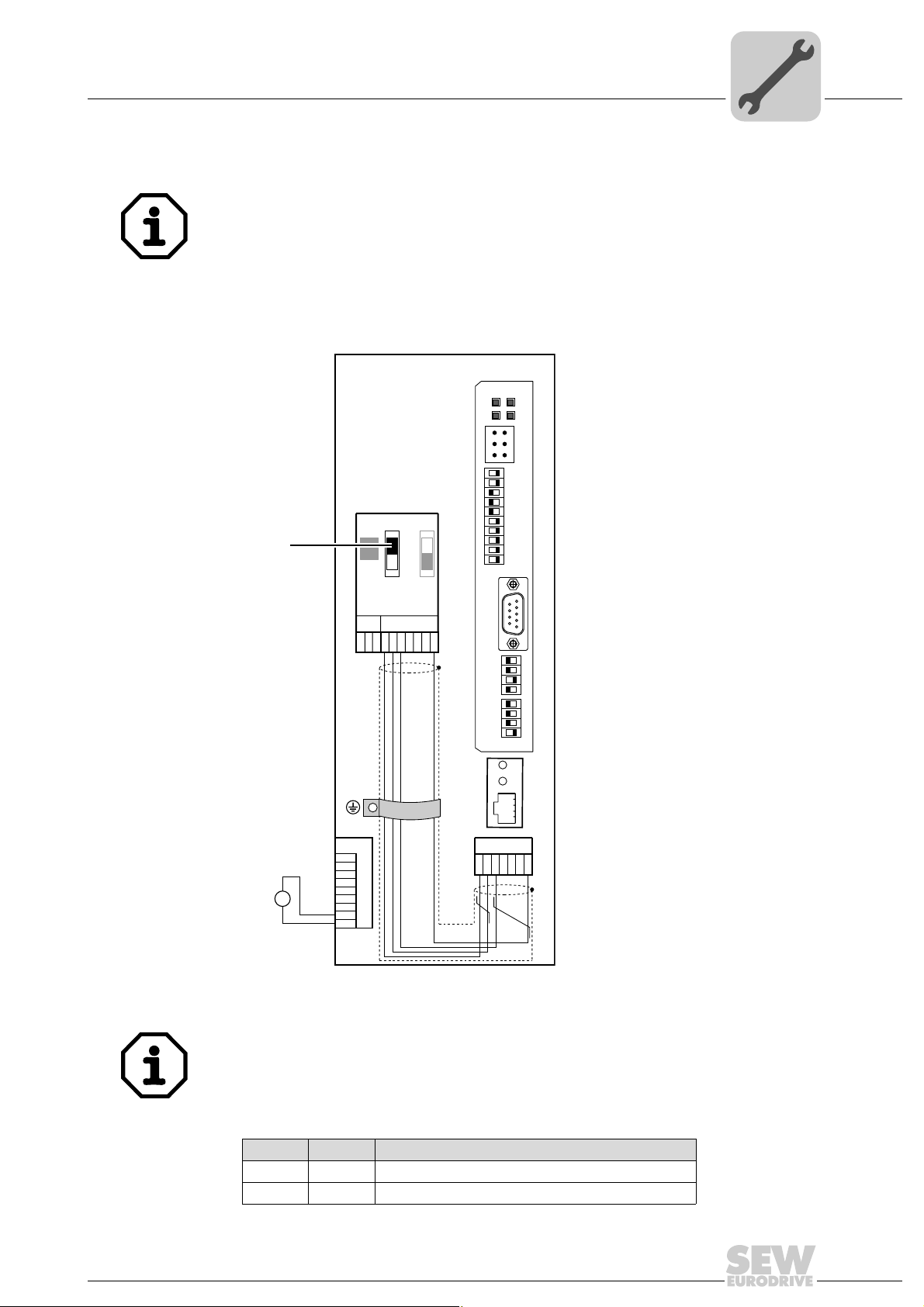
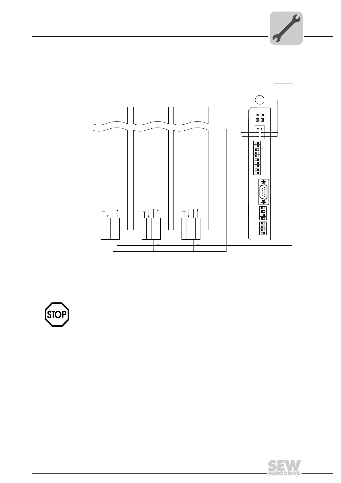
6.2.2 System bus connection
MOVITRAC® B
S1
S2
ON
OFF
X44
FSC11B
X46
X45
7
23456HL^
1
X12
1
2
3
4
5
6
7
8
9
24V
+
=
-
24V IO
GND
DFS11B
FSR
FDOBF
FDO
12
LS
34
56
PS
0
2
1
2
2
2
3
2
4
2
5
2
6
F-ADDRESS X31
2
7
2
8
2
9
2
01
5
9
X30
6
1
0
2
1
2
2
2
3
2
4
2
5
2
6
2
AS
01
H1
H2
X24
X26
1234567
Assembly and Installation Instructions
MOVITRAC® B
S1
ON
OFF
X44
FSC11B
X46
X45
23456HL ^
1
S2
7
MOVITRAC® B
S1
X44
FSC11B
X45
1
X46
23456HL ^
6
S2
ON
OFF
7
Figure 4: System bus connection
DFS Description
GND System bus reference
SC11 System bus high
SC12 System bus low
MOVITRAC® B Description
GND System bus reference
SC22 System bus low, outgoing
SC21 System bus high, outgoing
SC12 System bus low, incoming
SC11 System bus high, incoming
S12 System bus terminating resistor
Manual – Fieldbus Interface DFS11B PROFIBUS DP-V1 with PROFIsafe
61051AXX
23
Page 24

6
Phone: 800.894.0412 - Fax: 888.723.4773 - Web: www.clrwtr.com - Email: info@clrwtr.com
Assembly and Installation Instructions
Installing the DFS11B option card in MOVITRAC® B
Please note:
• Use a 2 x 2-core twisted pair and shielded copper cable (data transmission cable with
braided copper shield). Connect the shield flatly on both sides of the electronics
shield clamp of MOVITRAC
must meet the following specifications:
– Core cross section 0.75 mm
– Line resistance 120 Ω at 1 MHz
– Capacitance per unit length ≤ 40 pF/m at 1 kHz
• The permitted total cable length depends on the baud rate setting of the SBus:
– 250 kBaud: 160 m
– 500 kBaud: 80 m
– 1000 kBaud: 40 m
• Connect the system bus terminating resistor (S1 = ON) at the end of the system bus
connection. Switch off the terminating resistor on the other units (S1 = OFF). The
DFS11B gateway must always be connected either at the beginning o r the end of the
system bus connection and have a permanently installed terminating resistor.
®
. Also connect the ends of the shield to GND. The cable
2
• There must not be any potential displacement between the units connected with the
SBus. Take suitable measures to avoid potential displacement, such as connecting
the unit ground connectors using a separate cable.
• Point-to-point wiring is not permitted.
24
Manual – Fieldbus Interface DFS11B PROFIBUS DP-V1 with PROFIsafe
Page 25

Assembly and Installation Instructions
V
Phone: 800.894.0412 - Fax: 888.723.4773 - Web: www.clrwtr.com - Email: info@clrwtr.com
Assembling and installing the UOH11B gateway housing
6.3 Assembling and installing the UOH11B gateway housing
UOH11B
DFS11B
12
34
5
F-ADDRESS X31
01
X30
6
FSR
FDOBF
FDO
LS
6
PS
0
2
1
2
2
2
3
2
4
2
5
2
6
2
7
2
8
2
9
2
5
9
6
1
SEW Drive
SC11 Systembus +, CAN high
SC12 Systembus -, CAN low
GND, CAN GND
X26
X26:1 SC11 system bus +, CAN high
X26:2 SC12 system bus -, CAN low
X26:3 GND, CAN GND
X26:6 GND, CAN GND
X26:7 DC 24 V
0
2
1
2
2
2
3
2
4
2
5
2
6
2
AS
X24
X26
23456
1
01
H1
H2
7
+ 24
GND
61050AXX
The gateway housing has a power supply of DC 24 V that is connected to X26.
Connect the system bus terminating resistor at the end of the system bus connection.
Manual – Fieldbus Interface DFS11B PROFIBUS DP-V1 with PROFIsafe
25
Page 26

6
Phone: 800.894.0412 - Fax: 888.723.4773 - Web: www.clrwtr.com - Email: info@clrwtr.com
Assembly and Installation Instructions
Connection and terminal description of the DFS11B option
6.4 Connection and terminal description of the DFS11B option
Part number PROFIBUS / PROFIsafe® interface type DFS11B option: 1820 9629
The "PROFIBUS interface type DFS11B" option can only be used in conjunction with
MOVITRAC
®
B and MOVIDRIVE® MDX61B, not with MOVIDRIVE®MDX60B.
The DFS11B option must be plugged in the fieldbus slot.
Front view of
DFS11B
Description
Diagnostic LEDs: R
DFS11B
FSR
FDOBF
FDO
12
34
56
F-ADDRESS X31
01
9
X30
6
0
2
1
2
2
2
3
2
4
2
5
2
6
2
AS
01
LS
PS
0
2
1
2
2
2
3
2
4
2
5
2
6
2
7
2
8
2
9
2
5
1
X31 connection 1 (F_DO_M)
F-ADDRESS: DIP switch
for setting the failsafe
address
X30: PROFIBUS connection
61048AXX
ADDRESS: DIP switch for
setting the PROFIBUS
station address
1) The 24 V supply voltage(s) of the DFS11B and all stations connected to the fieldbus must be designed as safety e xtra-low voltage.
The voltage must lie within the limits defined in the technical data. Besides, the following voltage values must not be exceeded if a fault
occurs (according to EN 60950): Max. DC 60 V, max. DC 120 V for 200 ms.
DIP switch
Terminal
FS
BF
FDO
2 (F_DO_P)
3 (GND)
4 (24 V_LS)
5 (GND)
6 (24 V_PS)
0
2
1
2
2
2
3
2
4
2
5
2
6
2
7
2
8
2
9
2
X30:1
X30:2
X30:3
X30:4
X30:5
X30:6
X30:7
X30:8
X30:9
0
2
1
2
2
2
3
2
4
2
5
2
6
2
AS
Function
RUN – Component status (green)
Failsafe status – Status of the safety option (green during standard operation)
BUS FAULT – Bus status (red if a fault occurs, else disabled)
Failsafe output – Status of the safe output (orange)
Safe output
Safe output
Supply of the safe output
Supply of the safe output
Power supply to control electronics
Power supply to control electronics
1)
1)
Significance: 1
Significance: 2
Significance: 4
Significance: 8
Significance: 16
Significance: 32
Significance: 64
Significance: 128
Significance: 256
Significance: 512
N.C.
N.C.
RxD/TxD-P
CNTR-P
DGND (M5V)
VP (P5V/100 mA)
N.C.
RxD/TxD-N
N.C.
Significance: 1
Significance: 2
Significance: 4
Significance: 8
Significance: 16
Significance: 32
Significance: 64
Auto setup for gateway operation
Front view of
MOVITRAC
®
B, DFS11B
Description Function
and UOH11B
H1
H2
X24
LED H1 (red)
LED H2 (green)
X24 X terminal
System error (only for gateway functions)
Reserved
RS-485 interface for diagnostics via PC and
MOVITOOLS
(only applies to MOVITRAC
®
MotionStudio
®
B)
58129axx
26
Manual – Fieldbus Interface DFS11B PROFIBUS DP-V1 with PROFIsafe
Page 27

Assembly and Installation Instructions
Phone: 800.894.0412 - Fax: 888.723.4773 - Web: www.clrwtr.com - Email: info@clrwtr.com
Wiring diagram for safe technology
6.5 Wiring diagram for safe technology
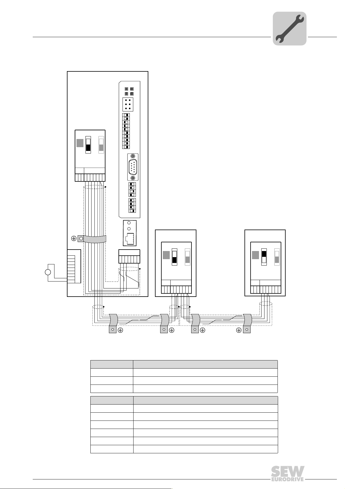
6.5.1 Wiring of individual MOVIDRIVE® MDX61B and MOVITRAC® B
6
MOVIDRIVE® B
MOVITRAC
®
B
X31:1 - F-DO_M
Reference potential for binary signal
Reference +24 V input safe stop
+24 V input safe stop
+24 V output
VO24
SVI24
SOV24
1 DGND
234
X17:
–
Voltage
supply
24V
DFS11B
GND
F-ADDRESS
01
AS
=
X31
12
34
56
0
2
1
2
2
2
3
2
4
2
5
2
6
2
7
2
8
2
9
2
9
X30
6
0
2
1
2
2
2
3
2
4
2
5
2
6
2
01
+
FSR
FDOBF
FDOFDO
LS
PSGND
5
1
[1]
X31:2 - F_DO_P
Cable
specification
61520AEN
[1] The 24 V supply voltage(s) of the DFS11B and all stations connected to the fieldbus must be
designed as safety extra-low voltage. The voltage must lie within the limits defined in the technical
data. Besides, the following voltage values must not be exceeded if a fault occurs (according to
EN 60950): Max. DC 60 V, max. DC 120 V for 200 ms.
2
Only connect cables with a core cross section of a minimum of 0.25 mm
2
to a maximum 1 mm
(AWG18) to the safety-related binary output F-DO (X31:1, X31:2)
(AWG23) up
of the DFS11B option. IEC 60999 does allow clamping without conductor end sleeves.
The maximum line length is 30 m.
Manual – Fieldbus Interface DFS11B PROFIBUS DP-V1 with PROFIsafe
27
Page 28

6
Phone: 800.894.0412 - Fax: 888.723.4773 - Web: www.clrwtr.com - Email: info@clrwtr.com
F-DO connection • The safety-related binary output is 2-pole, designed as P-M switch, and controlled
Assembly and Installation Instructions
Wiring diagram for safe technology
via PROFIsafe by a higher-level safety control.
• An actuator must generally be connected with the safe output F-DO with a 2-pole
connection between the P switch output and the M switch output (F-DO_P and FDO_M).
• It is not permitted to make a 1-pole connection between F-DO_P and the GND refer ence potential as doing so would cause an error as soon as the output is controlled.
• Internal testing of the safe output is cyclical. However, when decoupling takes place,
the test pulses at the connection terminals are not visible and need not be taken into
account during operation.
Internal tests and monitoring processes are able to detect various external faults:
When the output is switched on, the following faults can be detected.
• Short circuit between P output and reference potential
• Short circuit between M output and +24 V supply voltage
• Short circuit between P output and M output
When the output is switched off, the following faults can be detected.
• Short circuit between P output and reference potential
• Short circuit between M output and reference potential
• Short circuit between P output and +24 V supply voltage
• Short circuit between M output and +24 V supply voltage
Whenever the system detects a fault, it reverts to a safe status, i.e. all safety-related process values (F-DO) are set to "0". In addition, the safety component is passivated. The
fault is indicated by the "FS" LED (failsafe status) (→ page 35).
The 24 V supply voltage(s) of the DFS11B and all stations connected to the fieldbus
must be designed as safety extra-low voltage. The voltage must lie within the limits
defined in the technical data. In addition, the following voltage values must not be
exceeded if a fault occurs (according to EN 60950): Max. DC 60 V, max. DC 120 V for
200 ms.
28
Manual – Fieldbus Interface DFS11B PROFIBUS DP-V1 with PROFIsafe
Page 29
Assembly and Installation Instructions
P
Phone: 800.894.0412 - Fax: 888.723.4773 - Web: www.clrwtr.com - Email: info@clrwtr.com
Wiring diagram for safe technology
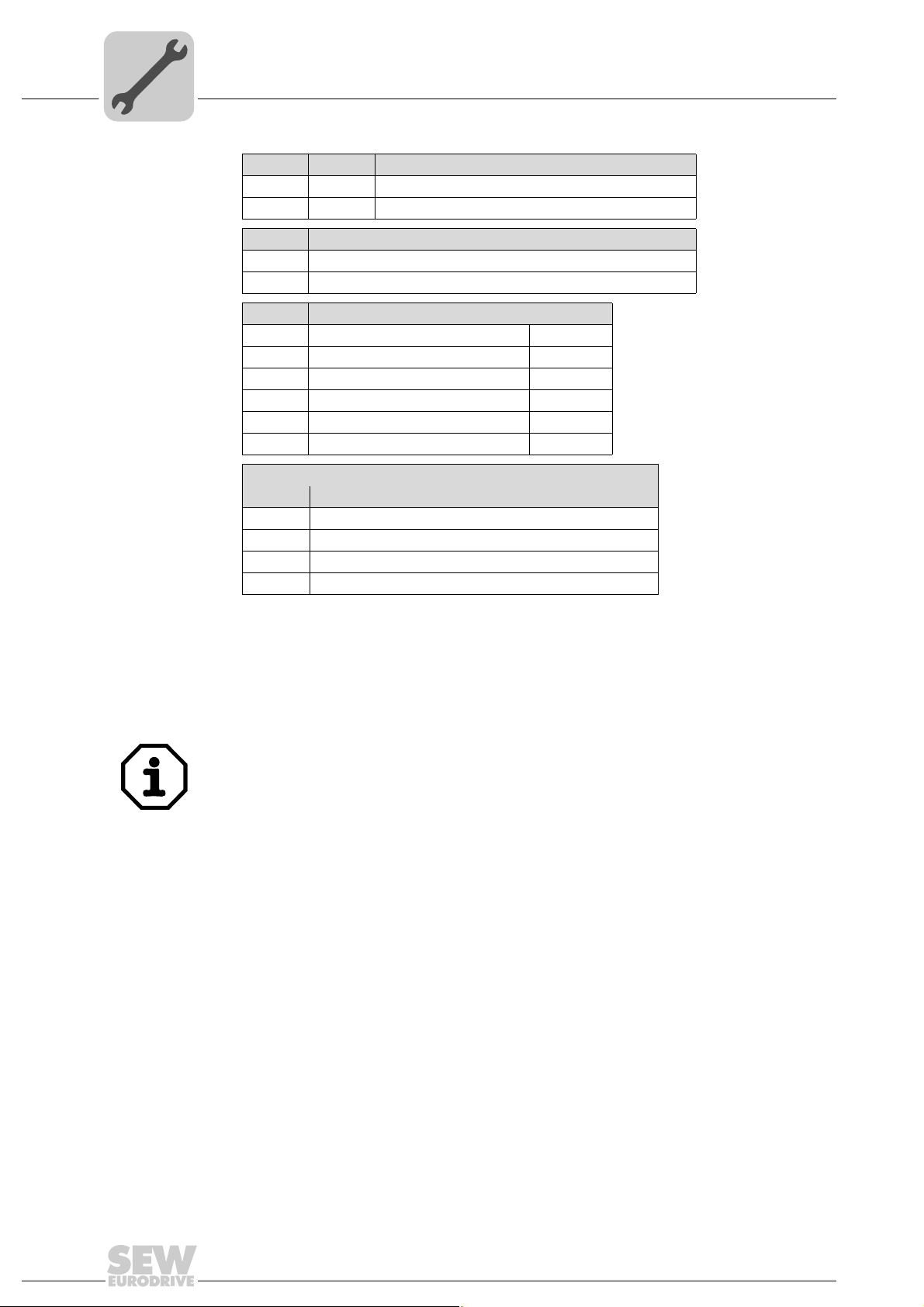
6.5.2 Group connection of MOVIDRIVE® MDX61B and MOVITRAC® B
6
MOVIDRIVE® B
MOVITRAC
X17:
®
Reference potential for binary signal
Reference +24 V input safe stop
+24 V input safe stop
+24 V output
VO24
SVI24
SOV24
1 DGND
234
B
MOVIDRIVE® B
MOVITRAC
Reference potential for binary signal
1 DGND
X17:
®
Reference +24 V input safe stop
+24 V output
VO24
SOV24
234
MOVITRAC
B
+24 V input safet stop
SVI24
X17:
®
B
Reference potential for binary signal
Reference +24 V input safe stop
+24 V input safe stop
+24 V output
VO24
SVI24
SOV24
1 DGND
234
MOVIDRIVE® B
Voltage
supply
24V
–
DFS11B
X31:1 - F-DO_M X31:2 - F_DO_
GND
F-ADDRESS
01
AS
=
X31
12
34
56
0
2
1
2
2
2
3
2
4
2
5
2
6
2
7
2
8
2
9
2
9
X30
6
0
2
1
2
2
2
3
2
4
2
5
2
6
2
01
+
FSR
FDOBF
FDOFDO
LS
PSGND
5
1
[1]
61521AEN
[1] The 24 V supply voltage(s) of the DFS11B and all stations connected to the fieldbus must be designed
as safety extra-low voltage. The voltage must lie within the limits defined in the technical data. In addition, the following voltage values must not be exceeded if a fault occurs (according to EN 60950):
Max. DC 60 V, max. DC 120 V for 200 ms.
Observe that the maximum current load of the F-DO safety-related binary output is
DC 1 A.
The DFS11B option card might be destroyed if the maximum current load (DC 1 A) of
the safety-related binary output F-DO is exceeded. If this happens, the safety function
of MOVIDRIVE
®
MDX61B / MOVITRAC® B is not ensured.
Manual – Fieldbus Interface DFS11B PROFIBUS DP-V1 with PROFIsafe
29
Page 30

6
Phone: 800.894.0412 - Fax: 888.723.4773 - Web: www.clrwtr.com - Email: info@clrwtr.com
Assembly and Installation Instructions
Wiring diagram for safe technology
Cable
specification
Only connect cables with a core cross section of a minimum of 0.25 mm2 (AWG23) up
2
to a maximum 1 mm
(AWG18) to the safety-related binary output F-DO (X31:1, X31:2)
of the DFS11B option. IEC 60999 does allow clamping without conductor end sleeves.
Power consumption of the safe contact X17 for MOVITRAC
X17 safety input, terminal 4
Voltage / cross section / time Min. Type Max. Unit
Safety-related 24 V supply voltage 19.2 24 30 VDC
Power consumption (size / capacity) Size 0 / 24 µF
Size 1 / 270 µF5
Size 2/2S / 270 µF6
Size 3 / 270 µF7.5
Size 4 / 270 µF8
Size 5 / 270 µF10
Cross section of the connection line of the safety-related 24 V voltage supply
Duration for disconnecting the safetyoriented 24 V supply voltage
Size 0
Sizes 1 to 5 10
®
3
––
0.75 – 1.5 mm
––
20
Watt
2
ms
Power consumption of the safe contact X17 for MOVIDRIVE
X17 safety input, terminal 4
MOVIDRIVE® MDX60/61B General electronics data
Safety contact X17:1
X17:2
X17:3
X17:4
Permitted cable cross section
Power consumption X17:4
Input capacitance X17:4
Time for restart
Time to inhibit output stage
Signal level
DGND: Reference potential for X17:3
VO24: U
other units.
SOV24: Reference potential for DC+24 V input "Safe stop" (safety contact)
SVI24: DC+24 V input "Safe stop" (safety contact)
One conductor per terminal: 0.08 ... 1.5 mm
Two conductors per terminal: 0.25 ... 1.0 mm
Size 0: 3 W
Size 1: 5 W
Size 2, 2S: 6 W
Size 3: 7.5 W
Size 4: 8 W
Size 5: 10 W
Size 6: 6 W
Size 0: 27 µF
Sizes 1 to 6: 270 µF
= 200 ms
t
A
≤ 100 ms
t
S
DC +19.2 V...+30 V= "1" = Contact closed
DC–30 V...+5 V= "0" = Contact open
= DC 24 V, only to supply X17:4 of the same unit; it cannot be used to supply
OUT
®
2
(AWG28...16)
2
(AWG23...17)
30
Manual – Fieldbus Interface DFS11B PROFIBUS DP-V1 with PROFIsafe
Page 31

6.6 PROFIBUS pin assignment
Phone: 800.894.0412 - Fax: 888.723.4773 - Web: www.clrwtr.com - Email: info@clrwtr.com
Connection to the PROFIBUS network using a 9-pin D-sub plug according to IEC 61158.
The T-bus connection must be ma de using a conn ector w ith th e corres pondin g config uration.
RxD/TxD- P
1
6
9
[1]
RxD/TxD-N
CNTR-P
DGND (M5V)
VP (P5V/100mA)
5
N.C.
Assembly and Installation Instructions
PROFIBUS pin assignment
[2]
3
8
4
5
6
9
[3]
6
Figure 5: Assignment of 9-pin D-sub plug to IEC 61158
[1] 9-pin D-sub connector
[2] Signal line, twisted
[3] Conductive connection over a large area is necessary between plug housing and the shield
®
6.6.1 Connecting MOVIDRIVE
/ MOVITRAC®B / PROFIBUS
As a rule, the DFS11B option is connected to the PROFIBUS system using a shielded
twisted-pair cable. Observe the maximum supported transmission rate when selecting
the bus connector.
The twisted-pair cable is connected to the PROFIBUS connector at pin 3 (RxD/TxD-P)
and pin 8 (RxD/TxD-N). Communication takes place via these two contacts. The RS-485
signals RxD/TxD-P and RxD/TxD-N must be connected to the same contacts in all
PROFIBUS stations. Otherwise, no communication is possible via the bus medium.
The PROFIBUS interface sends a TTL control signal for a repeater or fiber optic adapter
(reference = pin 5) via pin 4 (CNTR-P).
6.6.2 Baud rates greater than 1.5 MBaud
61500AXX
The DFS11B option with baud rates > 1.5 MBaud can only be operated with special
12 MBaud PROFIBUS connectors.
Manual – Fieldbus Interface DFS11B PROFIBUS DP-V1 with PROFIsafe
31
Page 32

6
Phone: 800.894.0412 - Fax: 888.723.4773 - Web: www.clrwtr.com - Email: info@clrwtr.com
Assembly and Installation Instructions
Shielding and routing bus cables
6.7 Shielding and routing bus cables
The PROFIBUS interface supports RS-485 transmission technology and requires the
cable type A to IEC 61158 as the physical medium for th e PROFI BUS. T his ca ble mus t
be a shielded, twisted-pair cable.
Correct shielding of the bus cable attenuates electrical interference that may occur in
industrial environments. Take the following measures to optimally shield bus cables:
• Manually tighten the mounting screws on the connectors, modules, and equipotential
bonding conductors.
• Use only connectors with a metal housing or a metallized housing.
• Connect the shielding in the connector over a wide surface area.
• Apply the shielding of the bus line on both ends.
• Route signal and bus cables in separate cable ducts. Do not route them parallel to
power cables (motor leads).
• Use metallic, grounded cable racks in industrial environments.
• Route the signal cable and the corresponding equipotential bonding close to each
other using the shortest possible route.
• Avoid using plug connectors to extend bus cables.
• Route the bus cables closely along existing grounding surfaces.
In case of fluctuations in the ground potential, a compensating current may flow via the
bilaterally connected shield that is also connected to the protective earth (PE). Make
sure you supply adequate equipotential bonding according in accordance with relevant
VDE regulations in such a case.
6.8 Bus termination
The DFS11B option is not provided with bus terminating resistors. This enables the bus
system to be put into operation more easily and reduces the number of error sour ces.
Use a connector with integrated bus terminating resistor if the DFS11B is loca ted at the
beginning or end of a PROFIBUS segment and only one PROFIBUS cable leads to the
DFS11B option.
Switch on the bus terminating resistors for this PROFIBUS connector.
32
Manual – Fieldbus Interface DFS11B PROFIBUS DP-V1 with PROFIsafe
Page 33

6.9 Setting the station address
Phone: 800.894.0412 - Fax: 888.723.4773 - Web: www.clrwtr.com - Email: info@clrwtr.com
Assembly and Installation Instructions
Setting the station address
6
Set the PROFIBUS station address using DIP switches 20 to 26 on the option card.
MOVIDRIVE
®
supports the address range 1 to 125.
DFS11B
FSR
FDOBF
FDO
12
LS
34
56
PS
0
2
1
2
2
2
3
2
4
2
5
2
6
F-ADDRESS X31
2
7
2
8
2
9
2
01
5
9
X30
6
1
0
2
1
2
2
2
3
2
4
2
5
2
6
2
AS
01
The default setting for the PROFIBUS station address is 4:
20 → Significance: 1 × 0 = 0
1
2
→ Significance: 2 × 0 = 0
2
→ Significance: 4 × 1 = 4
2
3
2
→ Significance: 8 × 0 = 0
4
2
→ Significance: 16 × 0 = 0
5
→ Significance: 32 × 0 = 0
2
6
2
→ Significance: 64 × 0 = 0
61048AXX
Any change made to the PROFIBUS station address duri ng ongoing operatio n does not
take effect immediately. The change only comes into effect when the inverter is switched
on again (power supply + +24 V OFF / ON). The inverter displays the current station
address in fieldbus monitor parameter P092 "Fieldbus address" (display with DBG60B
®
or MOVITOOLS
DFS11B
12
34
56
F-ADDRESS X31
01
X30
0
2
1
2
2
2
3
2
4
2
5
2
6
2
AS
MotionStudio / parameter tree).
FSR
FDOBF
FDO
LS
PS
0
2
1
2
2
2
3
2
4
2
5
2
6
2
7
2
8
2
9
2
5
9
6
01
1
Example: PROFIBUS station address set to 17
0
→ Significance: 1 × 1 = 1
2
1
→ Significance: 2 × 0 = 0
2
2
2
→ Significance: 4 × 0 = 0
3
2
→ Significance: 8 × 0 = 0
4
2
→ Significance: 16 × 1 = 16
5
→ Significance: 32 × 0 = 0
2
6
2
→ Significance: 64 × 0 = 0
61053AXX
Manual – Fieldbus Interface DFS11B PROFIBUS DP-V1 with PROFIsafe
33
Page 34

6
Phone: 800.894.0412 - Fax: 888.723.4773 - Web: www.clrwtr.com - Email: info@clrwtr.com
Assembly and Installation Instructions
Operation indicators of the DFS11B option
6.10 Operation indicators of the DFS11B option
6.10.1 PROFIBUS LEDs
The PROFIBUS interface DFS11B option card has 4 LEDs that indicate the current
status of the DFS11B option and the PROFIBUS system.
DFS11B
FSR
FDOBF
61054AXX
LED "R" RUN
(green)
LED "BF"
BUS-FAULT (red)
• The RUN LED (green) indicates that the bus electronics are operating correctly
RUN Cause of error Remedy
Green • PROFIBUS hardware OK. –
Orange • The card is booting. –
Off • Hardware defect in the bus electronics. • Switch the unit on again. Consult SEW
Flashes
2Hz
Flashes
1Hz
• PROFIBUS address is set higher than
125 or to 0.
• No error, only display. • The inverter is restarting.
service if the error occurs again.
• Use parameter P093 Fieldbus Address to
check the address set with the DIP
switches.
• Reset the inverter.
• The BUS FAULT LED (red) indicates a PROFIBUS DP fault.
BUS FAULT Cause of error Remedy
Red • Connection to the DP master has failed.
• Unit does not detect PROFIBUS baud
rate.
• Bus interruption.
• DP master not in operation
Off • Unit is currently exchanging data with
the DP master (data exchange).
Flashing • Unit has detected the baud rate, but is
not addressed by DP master.
• Unit was not configured in DP master or
configured incorrectly.
• Check the PROFIBUS DP connection
on the unit.
• Check the project planning of the DP
master.
• Check all cables in your PROFIBUS DP
network.
–
• Check the PROFIBUS address setting
on the DFS11B and in the project planning software of the DP master.
• Check the project planning of the DP
master.
• Use the GSD file SEW_600C.GSD with
the identifier MOVIDRIVE-DFS11B or
SEW_6009.GSD for gateway operation
with MOVITRAC
®
B.
34
Manual – Fieldbus Interface DFS11B PROFIBUS DP-V1 with PROFIsafe
Page 35

Assembly and Installation Instructions
Phone: 800.894.0412 - Fax: 888.723.4773 - Web: www.clrwtr.com - Email: info@clrwtr.com
Operation indicators of the DFS11B option
6
LED "FS" FAILSAFE STATUS
(green)
LED "FDO" FAILSAFE OUTPUT
(orange)
• The FAILSAFE STATUS LED (red) indicates the failsafe status on PROFIBUS DP.
FS Cause of error Remedy
Green • The DFS11B option is currently per-
Red • Fault status in the safety part.
Off • DFS11B option is currently in the ini-
Flashing
red/green
forming a cyclical data exchange with
the F-host (data exchange).
• Standard operating state.
• 24 V_O sup ply voltage is missing.
tialization phase.
A fault occurred in the safety part; cause
of the fault already remedied acknowledgement required.
–
• Read diagnostic in F-host.
• Eliminate the cause of the fault and
acknowledge in the F-host.
• Check voltage supply.
• Check configuration of the bus master.
Acknowledge fault in the F-host (reintegration).
• The FAILSAFE OUTPUT LED (red) indicates the failsafe status on PROFIBUS DP.
FDO State
Orange Output F-DO active
Off Output F-DO inactive (switched off)
WARNING
The "R", "BF", "FDO" and "FS" LEDs are not safety-oriented and may not be used as a
safety device.
LEDs for gateway communication status
H1
H2
X24
58129axx
LED H1 Sys-fault (red) Only for gateway function
Status Condition Description
Red System error Gateway is not configured or one of the
drives is inactive.
Off SBus ok Gateway is configured correctly.
Flashing Bus scan Bus is being checked by the gateway.
LED H2 H2 (green) is currently reserved.
X-terminal X24 is the RS-485 interface for diagnostics via PC and MOVITOOLS
MotionStudio.
®
Manual – Fieldbus Interface DFS11B PROFIBUS DP-V1 with PROFIsafe
35
Page 36

I
Phone: 800.894.0412 - Fax: 888.723.4773 - Web: www.clrwtr.com - Email: info@clrwtr.com
7
Project Planning and Startup
00
Validity of the GSD files for DFS11B
7 Project Planning and Startup
This section provides you with information on project planning for the DP master and
startup of the drive inverter for fieldbus operation.
Current versions of the GSD files for the DFS11B option are available on the SEW
homepageunder the heading "Software". Both GSD filescan be used at the same time
in one STEP 7 project. Once you have downloaded andunpacked the software, you
will have two directories for the operating modesPROFIBUS DP and PROFIBUS DP-V1.
7.1 Validity of the GSD files for DFS11B
PROFIBUS option
DFS11B074 firmware option 1:
DFS11B SEW_600C.GSD SEW_6009.GSD
Do not change or expand entries in the GSD file. SEW-EURODRIVE assumes no liability for malfunctions of the inverter caused by a modified GSD file.
MOVIDRIVE® MDX61B MOVITRAC® B / gateway
housing UOH11B
7.2 Project planning of PROFIBUS / PROFIsafe with MOVIDRIVE® GSD file
A GSD file is provided for project planning for the DP master. Copy this file into a special
directory of your project planning software.
Refer to the manuals for the appropriate project planning software for details on the
procedure.
7.2.1 GSD file for PROFIBUS DP-V1
Use the GSD file SEW_600C.GSD from the "DPV1" directory if you want to use the
parameter setting options of DP-V1 in addition to the stan dar d PROFIBUS DP communication to control the drive inverter.
This GSD file corresponds to GSD revision 4.
36
Manual – Fieldbus Interface DFS11B PROFIBUS DP-V1 with PROFIsafe
Page 37

Project Planning and Startup
Phone: 800.894.0412 - Fax: 888.723.4773 - Web: www.clrwtr.com - Email: info@clrwtr.com
Project planning of PROFIBUS / PROFIsafe with MOVIDRIVE® GSD file
The GSD files are assigned the name for PROFIBUS DP-V1 so they are easy to identify
and are displayed in a special subdirectory in the project planning software for the DPV1 master (see following screenshot).
I
7
00
7.2.2 Project planning procedure
Proceed as follows for project planning for MOVIDRIVE
1. Read the README_GSD_600C.PDF file that you received with the GSD file to
obtain further up-to-date information on project planning.
2. Install (copy) the GSD file according to the requirements of your project planning software. Once the file has been installed correctly, the device appears next to the slave
stations with the designation MOVIDRIVE+DFS11B.
3. Add the interface module under the name MOVIDRIVE+DFS11B to the PROFIBUS
structure and assign the station address.
4. Select the process data configuration required for your application (see page 38).
5. Enter the I/O or peripheral addresses for the configured data widths.
After project planning, you can start PROFIBUS DP. The red BF LED (BUS FAULT)
indicates the status of the project planning (OFF = project planning OK).
11635AEN
®
with PROFIBUS DP interface:
Manual – Fieldbus Interface DFS11B PROFIBUS DP-V1 with PROFIsafe
37
Page 38

I
Phone: 800.894.0412 - Fax: 888.723.4773 - Web: www.clrwtr.com - Email: info@clrwtr.com
7
Project Planning and Startup
Project planning of PROFIBUS / PROFIsafe with MOVIDRIVE® GSD file
00
7.2.3 DP configurations for MOVIDRIVE® MDX61B
The drive inverter must be given a specific DP co nfigur ation by the DP master to define
the type and number of input and output data used for transmission. You have the option
of
• Controlling the drive using process data
• Reading and writing all drive parameters using the parameter channel
• Using a data exchange medium of your choice between IPOS
controllor.
MOVIDRIVE
exchanging data between the DP master and the inverter. The following table provides
additional information about all possible DP configurations for the MOVIDRIVE
The "Process data configuration" column shows the n ame of the configuration. The texts
will also be displayed as selection list within the project planning software for the DP
master. The DP configurations column shows which configuration data is sent to the
inverter when the PROFIBUS DP connection is being established.
®
drive inverters make it possible to have different DP configurations for
plus®
and the
®
range.
Process data
configuration
1 PD MOVIDRIVE
2 PD MOVIDRIVE
3 PD MOVIDRIVE
4 PD MOVIDRIVE
5 PD MOVIDRIVE
6 PD MOVIDRIVE
7 PD MOVIDRIVE
8 PD MOVIDRIVE
9 PD MOVIDRIVE
10 PD MOVIDRIVE
Param + 1 PD MOVIDRIVE
Param + 2 PD MOVIDRIVE
Param + 3 PD MOVIDRIVE
Param + 4 PD MOVIDRIVE
Param + 5 PD MOVIDRIVE
Param + 6 PD MOVIDRIVE
Param + 7 PD MOVIDRIVE
Param + 8 PD MOVIDRIVE
Meaning / notes DP Configuration
(PD4-PD10 can only be used with IPOS
(PD4-PD10 can only be used with IPOS
(PD4-PD10 can only be used with IPOS
(PD4-PD10 can only be used with IPOS
(PD4-PD10 can only be used with IPOS
(PD4-PD10 can only be used with IPOS
(PD4-PD10 can only be used with IPOS
Parameter setting via 8 byte parameter channel
Parameter setting via 8 byte parameter channel
Parameter setting via 8 byte parameter channel
Parameter setting via 8 byte parameter channel
Parameter setting via 8 byte parameter channel
Parameter setting via 8 byte parameter channel
(PD4-PD10 can only be used with IPOS
Parameter setting via 8 byte parameter channel
Parameter setting via 8 byte parameter channel
Slot 1 (Fmodule)
®
control via 1 process data word 0x00 0x00 0xC0 0xC0 0xC0
®
control via 2 process data words 0x00 0x00 0xC0 0xC1 0xC1
®
control via 3 process data words 0x00 0x00 0xC0 0xC2 0xC2
®
control via 4 process data words
®
control via 5 process data words
®
control via 6 process data words
®
control via 7 process data words
®
control via 8 process data words
®
control via 9 process data words
®
control via 10 process data words
®
control via 1 process data word
®
control via 2 process data words
®
control via 3 process data words
®
control via 4 process data words
®
control via 5 process data words
®
control via 6 process data words
®
control via 7 process data words
®
control via 8 process data words
plus®
plus®
plus®
plus®
plus®
plus®
plus®
plus®
)
)
)
)
)
)
)
)
0x00 0x00 0xC0 0xC3 0xC3
0x00 0x00 0xC0 0xC4 0xC4
0x00 0x00 0xC0 0xC5 0xC5
0x00 0x00 0xC0 0xC6 0xC6
0x00 0x00 0xC0 0xC7 0xC7
0x00 0x00 0xC0 0xC8 0xC8
0x00 0x00 0xC0 0xC9 0xC9
0x00 0xC0 0x87 0x87 0xC0 0xC0 0xC0
0x00 0xC0 0x87 0x87 0xC0 0xC1 0xC1
0x00 0xC0 0x87 0x87 0xC0 0xC2 0xC2
0x00 0xC0 0x87 0x87 0xC0 0xC3 0xC3
0x00 0xC0 0x87 0x87 0xC0 0xC4 0xC4
0x00 0xC0 0x87 0x87 0xC0 0xC5 0xC5
0x00 0xC0 0x87 0x87 0xC0 0xC6 0xC6
0x00 0xC0 0x87 0x87 0xC0 0xC7 0xC7
Slot 2 (ParamChannel)
Slot 3 (PD channel)
38
Manual – Fieldbus Interface DFS11B PROFIBUS DP-V1 with PROFIsafe
Page 39

Project Planning and Startup
Phone: 800.894.0412 - Fax: 888.723.4773 - Web: www.clrwtr.com - Email: info@clrwtr.com
Project planning of PROFIBUS / PROFIsafe with MOVIDRIVE® GSD file
I
7
00
Process data
configuration
Param + 9 PD MOVIDRIVE® control via 9 process data words
Param + 10 PD MOVIDRIVE
Universal DP
configuration
Meaning / notes DP Configuration
Parameter setting via 8 byte parameter channel
®
Parameter setting via 8 byte parameter channel
(PD4-PD10 can only be used with IPOS
control via 10 process data words
plus®
If you select the "Universal Module" DP configuration (S7 HWConfig), you can structure
the DP configuration individually, although the following conditions must be complied
with:
Module 0 (DP identifier 0) defines the F-PD module .
Can only be configured via the master software because CRC32 must be calcu lated by
means of the settings made.
Module 1 (DP identifier 1) defines the param eter ch ann e l of the inv ert er.
To ensure the parameter settings are made correctly, you must always transfer the
parameter channel consistently for the entire length.
Slot 1 (Fmodule)
0x00 0xC0 0x87 0x87 0xC0 0xC8 0xC8
0x00 0xC0 0x87 0x87 0xC0 0xC9 0xC9
)
Slot 2 (ParamChannel)
Slot 3 (PD channel)
Length Function
0 Parameter channel deactivated
8 I/O bytes Parameter channel is used
Manual – Fieldbus Interface DFS11B PROFIBUS DP-V1 with PROFIsafe
39
Page 40

7
Phone: 800.894.0412 - Fax: 888.723.4773 - Web: www.clrwtr.com - Email: info@clrwtr.com
I
Project Planning and Startup
Project planning of PROFIBUS / PROFIsafe with MOVIDRIVE® GSD file
00
Module 2 (DP identifier 2) defines the proces s dat a ch a nne l of the inv erter.
In addition to the process data configuration predefined in the GSD file, you can also
specify process data configuration with 4, 5, 7, 8 and 9 process data words. Ensure that
the number of input and output words is always the same. If the lengths are different,
data cannot be exchanged. In this case, the BUS FAULT LED flashes; the parameter
P090 PD Configuration indicates the configuration error with 0PD.
Length Function
2 I/O bytes or 1 I/O word 1 process data word
4 I/O bytes or 2 I/O words 2 process data words
6 I/O bytes or 3 I/O words 3 process data words
8 I/O bytes or 4 I/O words 4 process data words
10 I/O bytes or 5 I/O words 5 process data words
12 I/O bytes or 6 I/O words 6 process data words
14 I/O bytes or 7 I/O words 7 process data words
16 I/O bytes or 8 I/O words 8 process data words
18 I/O bytes or 9 I/O words 9 process data words
20 I/O bytes or 10 I/O words 10 process data words
Note:
DFS11B does not support the "Compact identifier formats" coding.
Only use the setting "Integrity over entire length" for data transmission.
Data consistency Consistent data is data that has to be transmitted between the programmable controller
and the drive inverter as one block at all times and must never be transmitted sep arately.
Data integrity is especially important for the transmission of positioning values or
complete positioning tasks. Inconsistent transmission may contain data from different
program cycles of the automation device. This would lead to undefined values being
transmitted to the drive inverter.
For PROFIBUS DP, data communication between the programmable controller and
drive engineering devices is usually carried out with the setting "Data integrity over
entire length".
40
Manual – Fieldbus Interface DFS11B PROFIBUS DP-V1 with PROFIsafe
Page 41

Project Planning and Startup
Phone: 800.894.0412 - Fax: 888.723.4773 - Web: www.clrwtr.com - Email: info@clrwtr.com
Project planning for DP master with MOVITRAC® or gateway GSD file
7.3 Project planning for DP master with MOVITRAC® or gateway GSD file
I
7
00
This section provides information on project planning for the PROFIBUS DP master with
MOVITRAC
7.3.1 GSD file for operation in MOVITRAC
®
B and DFS11B gateway / UOH11B.
®
B and UOH11B gateway housing
11636AEN
Use the GSD file SEW_6009.GSD from the "DPV1" directory if you want to use the
DFS11B as gateway from PROFIBUS DP-V1 on the SBus to control the drive inverter.
This GSD file corresponds to GSD revision 5.
Refer to the manuals for the appropriate project planning software for details on the
procedure.
The unit master data files standardized by the PROFIBUS u ser organization can be read
by all PROFIBUS DP masters.
Project planning tool DP master File name
All DP project planning tools to EN
50170 (V2)
Siemens S7 hardware configuration for all S7 DP masters
Manual – Fieldbus Interface DFS11B PROFIBUS DP-V1 with PROFIsafe
for DP master standard SEW_6009.GSD
41
Page 42

I
Phone: 800.894.0412 - Fax: 888.723.4773 - Web: www.clrwtr.com - Email: info@clrwtr.com
7
7.3.2 PROFIBUS DP master startup
Project Planning and Startup
00
Project planning for DP master with MOVITRAC® or gateway GSD file
Supporting files for DFS11B gateway are available in the Internet at SEW Eurodrive website.
• Install the GSD file accord
the DP master. After successful installation, the "DFS11B gateway" device appears
in the list of slave stations.
• Insert the fieldbus interface into the PROFIBUS structure under the name "DFS11B
gateway" and assign the PROFIBUS address.
• Select the process data configuration required for your application (see the section
"Configuring the PROFIBUS DP interface" on page 43).
• Enter the I/O and / or peripheral addresses for the configured data widths.
• Save the configuration.
• Expand your application program by the data exchange with the fieldbus interface.
For S7, use the system functions for consistent data exchange for this purpose
(SFC14 and SFC15).
• The BUS FAULT LED at the fieldbus interface should extinguish after you have
saved the project, loaded it in the DP master and started the DP master. If this is not
the case, check the connections and terminating resistors of the PROFIBUS and the
configuration, especially the PROFIBUS address.
ing to the requirements of the project planning software for
42
Manual – Fieldbus Interface DFS11B PROFIBUS DP-V1 with PROFIsafe
Page 43

Project planning for DP master with MOVITRAC® or gateway GSD file
EURODRIVE
EURODRIVE
EURODRIVE
EURODRIVE
EURODRIVE
EURODRIVE
EURODRIVE
EURODRIVE
Phone: 800.894.0412 - Fax: 888.723.4773 - Web: www.clrwtr.com - Email: info@clrwtr.com
7.3.3 Configuring the PROFI BUS DP inte rf ac e
Project Planning and Startup
I
7
00
General
information
The inverter must be given a specific DP configuration by the DP master to define type
and number of input and output data used for the transmission. You have the opportunity
to control the drives via process data and to read and write all parameters of the fieldbus
interface via the parameter channel.
The figure shows a schematic view of the data exchange between automation device
(DP-V1 master), fieldbus interface (DP-V1 slave) and an inverter with process data
channel and parameter channel.
C1-Master
C2-Master C2-Master
Acyclic DP-V1
C2-Services
Unit = 8
Acyclic DP-V1
C2-Services
Acyclic DP-V1
C1-Services
Cyclic OUT Data
Param PD
Param PD
Cyclic IN Data
Unit = 1 Unit = 3
Unit = 0
DFP 21B
2
2
2
2
2
2
2
nc
ADDRESS
X30
RUN
BUS
FAULT
01
0
1
2
3
4
5
6
PROFIBUS DP-V1
Unit = 0
Unit = 5
= SBus-Address:12345678
Unit
B
®
EURODRIVEEURODRIVE
MOVITRAC
EURODRIVEEURODRIVE
EURODRIVEEURODRIVE
EURODRIVEEURODRIVE
EURODRIVEEURODRIVE
EURODRIVEEURODRIVE
EURODRIVEEURODRIVE
Figure 6: Data exchange with parameter data (Param) and process data (PD)
EURODRIVEEURODRIVE
59093AXX
Manual – Fieldbus Interface DFS11B PROFIBUS DP-V1 with PROFIsafe
43
Page 44

7
Phone: 800.894.0412 - Fax: 888.723.4773 - Web: www.clrwtr.com - Email: info@clrwtr.com
I
Project Planning and Startup
Project planning for DP master with MOVITRAC® or gateway GSD file
00
Configuring the
process data
One module for all
drives
The fieldbus interface allows for different DP configurations in the data exchange between DP master and fieldbus interface. The following table provides additional details
on all standard DP configurations of the fieldbus interfaces. The "Process data configuration" column shows the name of the configuration. The texts will also be displayed as
selection list within the project planning software for the DP master. The DP configurations column shows the type of configuration data sent to the fieldbus interface while the
link to PROFIBUS DP is being established. The configurations are determined by the
default process data width for SEW inverters of three process data words. The fieldbus
interface then distributes these process data words to the individual devices. The
parameter channel is used for setting the parameters of the DFS11B option and is not
passed on to the connected station s. The fieldbus interface accepts between 1 to 24
process data words with and without parameter channel.
The standard entries of the GSD file are based on the DFS11B Autosetup operating
mode and allow process data widths of 3 PD... 24 PD corresponding to 1 ... 8 inverters
connected to the fieldbus interface.
3 PDs are always assigned to any SBus station.
The process data are transmitted in one consistent data block for all inve rters connected
to the fieldbus interface. Thus, only system functions SFC14 and SFC15 need to be
called in STEP 7.
One module per
drive
One consistent data block e xists for each connec ted inve rter. Fr om the contr oller side,
this corresponds to the existing setup of several inverters with their own fieldbus interface. System functions SFC14 and SFC15 need to be called for each inverter in STEP 7.
Drive parameters of connected MOVITRAC® B inverters can only be accessed using the
DP-V1 parameter services.
44
Manual – Fieldbus Interface DFS11B PROFIBUS DP-V1 with PROFIsafe
Page 45

Project Planning and Startup
Phone: 800.894.0412 - Fax: 888.723.4773 - Web: www.clrwtr.com - Email: info@clrwtr.com
Project planning for DP master with MOVITRAC® or gateway GSD file
I
7
00
Process
data configuration
ONE module for all drives
Param 8 byte parame-
AS 1 drive
(3 PD)
AS 2 drives
(6 PD)
AS 3 drives
(9 PD)
AS 4 drives
(12 PD)
AS 5 drives
(15 PD)
AS 6 drives
(18 PD)
AS 7 drives
(21 PD)
AS 8 drives
(24 PD)
ONE module per drive
Param 8 byte parame-
AS 1 drive
(1 x 3 PD)
AS 2 drives
(2 x 3 PD)
AS 3 drives
(3 x 3 PD)
AS 4 drives
(4 x 3 PD)
AS 5 drives
(5 x 3 PD)
AS 6 drives
(6 x 3 PD)
AS 7 drives
(7 x 3 PD)
AS 8 drives
(8 x 3 PD)
Description Slot 1 Slot 2 Slot 3 Slot 4 Slot 5 Slot 6 Slot 7 Slot 8 Slot 9 Slot 10
ter channel
Control via 3 PD 00hex C0hex,
Control via 6 PD 00hex C0hex,
Control via 9 PD 00hex C0hex,
Control via 12 PD00hex C0hex,
Control via 15 PD00hex C0hex,
Control via 18 PD00hex C0hex,
Control via 21 PD00hex C0hex,
Control via 24 PD00hex C0hex,
ter channel
Control via
1x3PD
Control via
2x3PD
Control via
3x3PD
Control via
4x3PD
Control via
5x3PD
Control via
6x3PD
Control via
7x3PD
Control via
8x3PD
F-PD
mod-
00hex C0hex,
00hex C0hex,
00hex C0hex,
00hex C0hex,
00hex C0hex,
00hex C0hex,
00hex C0hex,
00hex C0hex,
00hex C0hex,
00hex C0hex,
ule
Param
eter
chan-
nel
87hex,
87hex
87hex,
87hex
Drive 1 Drive 2 Drive 3 Drive 4 Drive 5 Drive 6 Drive 7 Drive 8
C2hex,
C2hex
C5hex,
C5hex
C8hex,
C8hex
CBhex,
CBhex
CEhex,
CEhex
D1hex,
D1hex
D4hex,
D4hex
D7hex,
D7hex
C2hex,
C2hex
C2hex,
C2hex
C2hex,
C2hex
C2hex,
C2hex
C2hex,
C2hex
C2hex,
C2hex
C2hex,
C2hex
C2hex,
C2hex
C0hex,
C2hex,
C2hex
C0hex,
C2hex,
C2hex
C0hex,
C2hex,
C2hex
C0hex,
C2hex,
C2hex
C0hex,
C2hex,
C2hex
C0hex,
C2hex,
C2hex
C0hex,
C2hex,
C2hex
C0hex,
C2hex,
C2hex
C0hex,
C2hex,
C2hex
C0hex,
C2hex,
C2hex
C0hex,
C2hex,
C2hex
C0hex,
C2hex,
C2hex
C0hex,
C2hex,
C2hex
C0hex,
C2hex,
C2hex
C0hex,
C2hex,
C2hex
C0hex,
C2hex,
C2hex
C0hex,
C2hex,
C2hex
C0hex,
C2hex,
C2hex
C0hex,
C2hex,
C2hex
C0hex,
C2hex,
C2hex
C0hex,
C2hex,
C2hex
C0hex,
C2hex,
C2hex
C0hex,
C2hex,
C2hex
C0hex,
C2hex,
C2hex
0hex,
C
C2hex,
C2hex
C0hex,
C2hex,
C2hex
C0hex,
C2hex,
C2hex
C0hex,
C2hex,
C2hex
Manual – Fieldbus Interface DFS11B PROFIBUS DP-V1 with PROFIsafe
45
Page 46

7
Phone: 800.894.0412 - Fax: 888.723.4773 - Web: www.clrwtr.com - Email: info@clrwtr.com
I
Project Planning and Startup
Project planning for DP master with MOVITRAC® or gateway GSD file
00
"Universal module"
DP configuration
7.3.4 Operating mode (DP-V1 mode)
The "Universal Module" (e.g. in STEP7) lets yo u to set the parameters of the fieldb us
interface deviating from the preset default values of the GSD file. This is useful, for
example, if you want to operate several inverters with different process data words at
the fieldbus interface.
Observe the following conditions:
• Module 1 defines the parameter channel of the inverter. Entering 0 switches off the
parameter channel. Entering the value 0xC0 0x87 0x87 will activate the parameter
channel with 8 bytes length.
• The following modules determine the process data length of the fieldbus interface at
the PROFIBUS. The total process data length of all following modules must be
between 1 and 24 words. For safety reasons, the modules must be listed with data
integrity. Ensure that an inverte r connected to the fieldb us interface is represente d
by such a consistent module entry.
• Only the compact identifier format is permitted.
The DP-V1 operating mode can usually be activated during project planning for a C1
master. All DP slaves, which have the DP-V1 functions enabled in their GSD files and
which support DP-V1, will then be operated in DP-V1 mode. Standard DP slaves will still
run via PROFIBUS DP. This ensures mixed mode for DP-V1 and DP-capable modu les.
Depending on the master functionality, a DP-V1 capable station, that was configured
using the DP-V1 GSD file, can run in the "DP" operating mode.
46
Manual – Fieldbus Interface DFS11B PROFIBUS DP-V1 with PROFIsafe
Page 47

Project planning for DP master with MOVITRAC® or gateway GSD file
Phone: 800.894.0412 - Fax: 888.723.4773 - Web: www.clrwtr.com - Email: info@clrwtr.com
7.3.5 Auto setup for gateway operation
The auto setup function lets you start up the DFS11B as gateway without a PC. It is
activated via the auto setup DIP switch (see section "Assembling and installing the
UOH11B gateway" on page 25).
Switching on the Auto setup DIP switch causes the function to be performed on ce. The
Auto setup DIP switch must then remain in the ON position. The function can be
reactivated by turning the DIP switch off and back on again.
As a first step, the DFS11B searches for drive inverters on the SBus below its hierarchical level. This process is indicated by the H1 LED (system error) flashing briefly. For this
purpose, different SBus addresses must be set for the drive inverters (P813). SEWEURODRIVE recommends assigning the addresses beginning with address 1 in
ascending order based on the arrangement of inverters in the control cabinet. The
process image on the fieldbus side is expanded by three words fo r ea ch detected drive
inverter.
The H1 LED remains lit if no drive inverter was detected. A total of up to eight drive
inverters is taken into account. The following figure shows the process image for three
drive inverters with three words each of process output data and process input data.
After the search is completed, the DFS11B periodically exchanges three process data
words with each connected drive inverter. The process outp ut data are fetched from the
fieldbus, divided into blocks of three and transmitted. The drive inverters read the
process input data, put them together and send them to the fieldbus master.
The cycle time of the SBus communication requires 2 ms for each station.
For an application with 8 inverters on the SBus, the cycle time of the process data
update is then 8 x 2 ms = 16 ms.
Project Planning and Startup
I
7
00
The DFS11B option saves the process data once during auto setup. This is the reason
why you have to activate Auto setup again if you change the process data assignment
of the drive inverters connected to the DFS11B option. At the same time, the process
data assignments of the connected drive inverters may not be changed dynamically
after Auto setup.
Manual – Fieldbus Interface DFS11B PROFIBUS DP-V1 with PROFIsafe
47
Page 48

7
Phone: 800.894.0412 - Fax: 888.723.4773 - Web: www.clrwtr.com - Email: info@clrwtr.com
I
Project Planning and Startup
Project planning for DP master with MOVITRAC® or gateway GSD file
00
The following figure shows the data exchange between DP-V1 master, DFS and
inverter.
Figure 7: Data exchange DP-V1 master – UFP – inverter
DFS
61055AXX
48
Manual – Fieldbus Interface DFS11B PROFIBUS DP-V1 with PROFIsafe
Page 49

Project Planning and Startup
Phone: 800.894.0412 - Fax: 888.723.4773 - Web: www.clrwtr.com - Email: info@clrwtr.com
Setting the MOVIDRIVE® MDX61B drive inverter
7.4 Setting the MOVIDRIVE® MDX61B drive inverter
The following settings are required for simple fieldbus operation.
I
7
00
11638AXX
®
However, to control the MOVIDRIVE
first switch the drive inverter to control signal source (P101) and setpoint so urce (P100)
= FIELDBUS. The FIELDBUS setting means the drive inverter parameters are set for
control and setpoint entry via PROFIBUS. The MOVIDRIVE
then responds to the process output data transmitted from the master programmable
controller.
The parameters of the MOVIDRIVE
via PROFIBUS without any further settings once the PROFIBUS option card has been
installed. For example, all parameters can be set by the master programmable controller
after power-on.
Activation of the control signal source and setpoint source FIELDBUS is signaled to the
machine controller using the "Fieldbus mode active" bit in the status word.
MDX61B drive inverter via PROFIBUS, you must
®
MDX61B drive inverter
®
MDX61B drive inverter can be set straight away
Manual – Fieldbus Interface DFS11B PROFIBUS DP-V1 with PROFIsafe
49
Page 50

I
Phone: 800.894.0412 - Fax: 888.723.4773 - Web: www.clrwtr.com - Email: info@clrwtr.com
7
Project Planning and Startup
Setting the MOVITRAC® B frequency inverter
00
For safety reasons, you must also enable the MOVIDRIVE® MDX61B drive inverter at
the terminals for control via the fieldbus system. Therefore, you must wir e and pr ogram
the terminals in such a way that the inverter is enabled via the input terminals. For
example, the simplest way of enabling the drive inverter at the terminals is to connect
the DIØØ (function / CONTROL INHIBIT) input terminal to a +24 V signal and to program
input terminals DIØ1 ... DIØ3 to NO FUNCTION.
The procedure for startup of the MOVIDRIVE
connection is described on the next page.
7.5 Setting the MOVITRAC®B frequency inverter
The following settings are required for simple fieldbus operation.
®
MDX61B drive inverter with a fieldbus
50
Manual – Fieldbus Interface DFS11B PROFIBUS DP-V1 with PROFIsafe
11329AEN
Page 51

Project Planning and Startup
Phone: 800.894.0412 - Fax: 888.723.4773 - Web: www.clrwtr.com - Email: info@clrwtr.com
I
Setting the MOVITRAC® B frequency inverter
00
To control the inverter via PROFIBUS, you first have to switch the drive inverter to
control signal source (P101) and setpoint source (P100) = SBus. The SBus setting
means the inverter parameters are set for control and setpoint entry via gateway. The
MOVITRAC
from the master programmable controller.
It is necessary to set the SBus1 timeout interval (P8 15) to a value othe r than 0 m s for
the MOVITRAC
tion. SEW-EURODRIVE recommends a value in the range between 50 and 200 ms.
Activation of the control signal source and setpoint source SBus is signaled to the
higher-level controller using the "SBus mode active" bit in the status word.
For safety reasons, you must also enable the inverter at the terminals for control via the
fieldbus system. Therefore, you must wire and program th e terminals in such a way tha t
the inverter is enabled via the input terminals. The simplest way of en abling the invert er
at the terminals is, for example, to connect the DIØ1 (function CW/STOP) input terminal
to a +24 V signal and to program the remaining input terminals to NO FUNCTION.
Set the parameter P881 SBus address to values between 1 and 8 in ascending order.
The SBus address 0 is used by the DFS11B gateway and must therefore not be used.
®
frequency inverter then responds to the process output data transmitted
®
B frequency inverter to stop in the event of a faulty SBus communi ca-
7
Manual – Fieldbus Interface DFS11B PROFIBUS DP-V1 with PROFIsafe
51
Page 52

I
Phone: 800.894.0412 - Fax: 888.723.4773 - Web: www.clrwtr.com - Email: info@clrwtr.com
7
Project Planning and Startup
Project planning of PROFIsafe with STEP7
00
7.6 Project planning of PROFIsafe with STEP7
Configure the fail-safe DFS fieldbus interface as usual under STEP7 HW Config for
PROFIBUS-DP operation.
To ensure fault-free DFS operation with PROFIsafe, you must obtain the optional
package entitled "Distributed Safety (V5.4 or later)" for configuring and setting the
parameters of the module under STEP7.
7.6.1 Hardware structur e
• Wire the PROFIBUS line structure
• Set the PROFIBUS and fail-safe addresses:
– Set the PROFIsafe address on the DFS (factory setting: address 255). Set the
PROFIsafe address using the DIP switch. You may set an address ranging
from 1 to 1022.
– Ensure that the setting on the DFS matches the PROFIsafe address in STEP7
HW Config.
The following figure shows the DIP switch setting for address 1012 in the
example.
F Address
0
16754328910
2
x 0 = 0
1
2
x 0 = 0
2
x 1 = 4
2
3
2
x 0 = 0
4
2
x 1 = 16
5
x 1 = 32
2
26 x 1 = 64
7
2
x 1 = 128
8
x 1 = 256
2
9
2
x 1 = 512
01
Figure 8: Addressing example using address 1012
1012
61057AXX
52
Manual – Fieldbus Interface DFS11B PROFIBUS DP-V1 with PROFIsafe
Page 53

7.6.2 Installing the GSD file
Phone: 800.894.0412 - Fax: 888.723.4773 - Web: www.clrwtr.com - Email: info@clrwtr.com
Use the following GSD and image files for the DFS option card with PROFIsafe
functionality:
Project Planning and Startup
Project planning of PROFIsafe with STEP7
I
7
00
PROFIBUS option
DFS11B074 firmware option 1:
DFS11B SEW_600C.GSD SEW_6009.GSD
Once you have installed the GSD file, the module appears in the Hardware catalog of
STEP7 / HW Config under:
MOVIDRIVE® MDX61B MOVITRAC® B / gateway
housing UOH11B
Manual – Fieldbus Interface DFS11B PROFIBUS DP-V1 with PROFIsafe
11609AEN
53
Page 54

I
Phone: 800.894.0412 - Fax: 888.723.4773 - Web: www.clrwtr.com - Email: info@clrwtr.com
7
Project Planning and Startup
Project planning of PROFIsafe with STEP7
00
7.6.3 Configuring the DFS in HW Config
In HW Config, drag and drop the device entry "Gateway DFP/DFS" or "MOVIDRIVE
DFS11B" to the bus cable.
If slot 1 is not configured, you can operate the DFS like the standard fieldbus module.
No safety function via PROFIsafe is available in this configuration.
11610AXX
54
Manual – Fieldbus Interface DFS11B PROFIBUS DP-V1 with PROFIsafe
Page 55

Project planning of PROFIsafe with STEP7
Phone: 800.894.0412 - Fax: 888.723.4773 - Web: www.clrwtr.com - Email: info@clrwtr.com
7.6.4 Project planning for a new configuration
You will usually have to adjust the project planning in HW Config to your specific
application. To do so, assign the relevant modules to slots 1 to 3. Each slot has a specific
function assigned to it. The function of the slot will be displayed in the "DP identifier"
column after you have deleted the default configuration of slots 1to 3. The following
table gives an overview of the slot functionality.
Slot DP identifier Description of the function
1 F channel The PROFIsafe
2 Parameter
channel
3 PD channel The process data for controlling MOVIDRIVE
following modules:
• "F-module I/O (2-byte)" = PROFIsafe
• "F-module I/O (8-byte)" = PROFIsafe
• "Empty" = PROFIsafe channel is not used
IMPORTANT
If no PROFIsafe channel is configured, the safety-oriented part of the DFS
option remains in safe condition and the safe output FDO0 remains disabled.
The 8-byte parameter channel is configured in slot 2 if you want to reach
parameters of the DFS option via the cyclical PROFIBU DP data. This
channel is not safety-oriented and can be assigned with the following
modules:
• "Param (4 words)" = Parameter channel is used
• "Empty" = Parameter channel is not used
ured in slot 3. Always the same number of process data is transmitted in
direction of the input and output. The process data channel must always
be configured. This channel is not safety-oriented. See section 7.2 on
page 36 and section 7.3 on page 41.
Project Planning and Startup
®
channel is configured in slot 1. It can be assigned the
®
option
option
channel is used for DFS11B
®
channel is used for DFS11B
®
I
7
00
/MOVITRAC® are config-
Manual – Fieldbus Interface DFS11B PROFIBUS DP-V1 with PROFIsafe
11637AEN
55
Page 56

I
Phone: 800.894.0412 - Fax: 888.723.4773 - Web: www.clrwtr.com - Email: info@clrwtr.com
7
Project Planning and Startup
Project planning of PROFIsafe with STEP7
00
7.6.5 Setting the parameters of the PROFIsafe properties
Set the parameters of the PROFIsafe properties of the fail-safe DFS in STEP7 HW
Config by double-clicking the configured F-module in slot 1. The [DP slave properties]
window opens with the tab pages [Adress/identifier], [Set parameters] and [PROFIsafe].
The F_Dest_Add parameter displays the PROFIsafe address that was previously set
using the F-address DIP switch of the DFS module.
7.6.6 Description of the F-parameters
When the PROFIBUS DP starts up, the PROFIBUS DP master sends the safetyrelevant parameters for PROFIsafe operation in an F pa rameter block to the DFS option.
The parameters will then be checked for plausibility in the safety-oriented part of the
DFS. The DFS does not start data exchange on PROFIBUS DP until this F parameter
block is acknowledged positively.
Below is a list of the safety-oriented parameters which are passed on to the DFS option .
You can set the following parameters for your safety application:
• F_CRC_Length
• F_Par_Version
• F_Dest_Add
• F_WD_Time
Parameter
"F_Check_SeqNr
" (fix)
This parameter determines whether the Ready counter (consecutive number) is to be
included in the consistency check (CRC calculation) of the F user data telegram.
The DFS option supports the following setting:
• F_Check_SeqNr = "No check"
59779AXX
56
Manual – Fieldbus Interface DFS11B PROFIBUS DP-V1 with PROFIsafe
Page 57

Project Planning and Startup
Phone: 800.894.0412 - Fax: 888.723.4773 - Web: www.clrwtr.com - Email: info@clrwtr.com
Project planning of PROFIsafe with STEP7
I
7
00
Parameter
"F_SIL" (fix)
Parameter
"F_CRC_Length"
(can be set)
Parameter
"F_Par_Version"
(can be set)
Parameter
"F_Source_Add"
(fix)
This parameter enables F stations to check if the safety category matches that of the FHost. Depending on the risk, different safety circuits with different s afety classes SIL 1
to SIL 3 (SIL = Safety Integrity Level), apply in these safety-relevant cases.
The DFS option supports the following setting:
• F_SIL = SIL 3
Depending on the length of the F user data (process values) and the PROFIsafe version,
the length of the required CRC check value varies. This parameter communicates the
anticipated length of the CRC2 key in the safety telegram to the F component.
The DFS option handles user data that is less than 12 bytes in length, so that with
PROFIsafe V1, a 2 byte CRC is used and with PROFIsafe V2, a 3 byte CRC is used.
The DFS option supports the following setting:
• F_CRC_Length = 2 byte CRC (only with PROFIsafe
3 byte CRC (only with PROFIsafe
This parameter identifies the PROFIsafe version implemented in the DFS option. You
can choose between PROFIsafe
The PROFIsafe addresses are used for unique identification of the source
(F_Source_Add) and destination (F_Dest_Add). The combination of source and destination address must be unique throughout the netwo rk and station. The source address
F_Source_Add is automatically provided by STEP7 depending on the master configuration.
Values ranging from 1 to 65534 can be entered in parameter "F_Source_Add".
You cannot directly edit this parameter in STEP7 HW Config.
®
V1 and PROFIsafe V2®. DFS supports both versions.
®
V1)
®
V2)
Parameter
"F_Dest_Add"
(can be set)
Parameter
"F_WD_Time"
(can be set)
The PROFIsafe address you have set using the F-address DIP switch on the DFS
module is displayed on this parameter.
Values ranging from 1 to 1023 can be entered in parameter "F_Dest_Add".
This parameter defines a monitoring time in the fail-safe part of the DFS option.
During this monitoring period , an up-to-date safety telegram must arrive from the F-
CPU. Otherwise the DFS option reverts to safe status.
Select a monitoring time of a sufficient len gth so that communication can tolerate mes-
sage delays, but also sufficiently short enough for your sa fety a pp licatio n to run withou t
restriction.
For the DFS option, you can define the "F_WD_Time" par amete r in step s from 1 ms to
10 s.
Manual – Fieldbus Interface DFS11B PROFIBUS DP-V1 with PROFIsafe
57
Page 58

I
Phone: 800.894.0412 - Fax: 888.723.4773 - Web: www.clrwtr.com - Email: info@clrwtr.com
7
Project Planning and Startup
Project planning of PROFIsafe with STEP7
00
7.6.7 Safety diagnostics using PROFIBUS DP
The status of PROFIsafe communication and DFS11B option error messages is transmitted to the DP master via a status PDU in accordance with the PROFIBUS DPV1
standard.
The following figure shows how the diagnostic data is organized for PROFIsafe communication via slot 1. The F-PD module for the DFS11B option is configured in slot 1.
Byte 11 is used for transmitting diagnostic messages. These are defined in the
PROFIsafe specifications.
Bytes 12 and 13 transmit the status and fault status of the DFS11B option to the higherlevel DP master.
The figure below shows the structure of diagnostic data for PROFIBUS DPV1:
Bytes 1...6 Byte 7 Byte 8 Byte 9 Byte 10 Byte 11 Byte 12 Byte 13
6 bytes
Standard diagnostics
... 0x07 0x81 0x00 0x00 PROFIsafe F-State 1
Header
↑↑↑↑↑ ↑
7 bytes
module-
specific
diagnostics
Status block
with status
Status
Type
0x81 =
message
Slot
Number
0x00 =
Slot 1
(PROFIsafe
option)
Status block
Status
Specifier
No DPV1
specifier
®
Diag User
Data 0
PROFIsafe
diagnostic
information
in accordance with
PROFIsafe
profile V2.0
Diag User
Data 1
Cyclical F_State
of the DFS11B option
Diag User
Data 2
Diagnostic messages of the
PROFIsafe layer
The table below shows the diagnostic messages of the PROFIsafe layer:
Byte 11 PROFIBUS diagnostic message
0hex / 0dec Kein Fehler ---
40hex /
64dec
41hex /
65dec
42hex /
66dec
43hex /
67dec
44hex /
68dec
45hex /
69dec
46hex /
70dec
47hex /
71dec
(German)
F_Dest_Add stimmt nicht überein Mismatch of F_Dest_Add
F_Dest_Add ist ungültig F_Dest_Add not valid
F_Source_Add ist ungültig F_Source_Add not valid
F_WD_Time ist 0 ms F_WD_Time is 0 ms
F_SIL Level größer max SIL Level F_SIL exceeds SIL f. application
Falsche F_CRC_Length F_CRC_Length does not match
Falsche F-Parameter Version F parameter incorrectly set
Fehler im CRC1-Wert CRC1 fault
PROFIBUS diagnostic message
(English)
For more information on the meaning of fault messages and troubleshooting procedures
refer to the PROFIBUS-DP master manuals.
58
Manual – Fieldbus Interface DFS11B PROFIBUS DP-V1 with PROFIsafe
Page 59

Project Planning and Startup
Phone: 800.894.0412 - Fax: 888.723.4773 - Web: www.clrwtr.com - Email: info@clrwtr.com
Project planning of PROFIsafe with STEP7
I
7
00
Fault codes of the
DFS11B option
The following table shows the fault codes of the DFS11 B op tio n:
Byte 12 Byte 13 Designation
(German)
00
hex
/ 00
dec
00
01
02
03
04
14
15
32
hex
hex
hex
hex
hex
hex
hex
hex
/ 00
/ 01
/ 02
/ 03
/ 04
/ 20
/ 21
/ 50
kein Fehler --- See section "Fault
dec
Interner Ablauffehler Internal sequence fault
dec
Interner Systemfehler Internal system fault
dec
Fehler Kommunikation Communication fault
dec
Fehler Elektronikversor-
dec
gung
Interner Fehler am
dec
sicheren Eingang (F-DIx)
Kurzschluss am sicheren
dec
Eingang (F-DIx)
Interner Fehler am
dec
sicheren Ausgang
(F-DOx)
33
34
6F
7F
hex
hex
hex
hex
/ 51
/ 52
/ 111
/ 127
Kurzschluss am sicheren
dec
Ausgang (F-DOx)
Überlast am sicheren
dec
Ausgang (F-DOx)
Interner Kommunikation-
dec
sfehler zur DFS11B
Fehler Initialisierung
dec
DFS11B
Designation
(English)
Circuitry supply voltage fault
Internal fault failsafe
input
Short circuit failsafe
input
Internal fault failsafe
output
Short circuit failsafe
output
Overload failsafe output
Internal communication timeout
F init fault
Meaning / correction procedure
table PROFIsafe
DFS11B option" on
page 124.
Manual – Fieldbus Interface DFS11B PROFIBUS DP-V1 with PROFIsafe
59
Page 60

I
Phone: 800.894.0412 - Fax: 888.723.4773 - Web: www.clrwtr.com - Email: info@clrwtr.com
7
Project Planning and Startup
Project planning of PROFIsafe with STEP7
00
7.6.8 Response times of PROFIsafe option DFS
Response times play a decisive part in the design and execution of safety functions of
systems and machines. In order to matc h the response time to the requirements of a
safety function, always take the entire system from sensor (or control device) to actuator
into account. The following times are decisive:
• Response times of the connected sensors
• Internal response time of the failsafe inputs (filter time + processing time)
• PROFIsafe cycle time
• Processing time (cycle time) in the safety control
• PROFIsafe monitoring time "F_WD_Time"
• Internal reaction time of the safe outputs
• Response or switching time of the actuator
Response
sequence in conjunction with the
PROFIsafe option
DFS
The following figure shows the response sequence in conjunction with PROFIsafe
option DFS:
MOVIDRIVE / MOVITRAC
DFS
t
µ
C
t
t
ps
F-CPU
t
µ
C
DFS PROFIsafe option
F CPU Safety control
µC Micro-controller
F-DO Safe output
A Actuator for activating the STO
Response time from safety control to actuator for controlling the STO
t3 Processing time in safety control To be generated from the safety control
t
PROFIsafe cycle time According to safety control data
ps
t4 Internal response time of the safe output 25 ms
t5 Response or switching time of the actuator According to the manufacturer
Actuator switches after xx ms Total
F-DO
4
3
5
A
62402AXX
60
Manual – Fieldbus Interface DFS11B PROFIBUS DP-V1 with PROFIsafe
Page 61

Project Planning and Startup
Phone: 800.894.0412 - Fax: 888.723.4773 - Web: www.clrwtr.com - Email: info@clrwtr.com
Procedure for starting up DFS11B with MOVIDRIVE® MDX61B
PROFIsafe monitoring time ("F_ WD_Time") plays an important role in determining the
maximum response time for a safety requirement. This time must be set in the safety
control for the DFS option.
For the response sequence described above, with the PROFIsafe monitoring time
defined as t
time for an event at the safety sensor to switching the actuator:
, the following formula is used to calculate the maximum total response
WD
I
7
00
t
response,max
= max {tps + t3 + tps + t4} + t5
7.7 Procedure for starting up DFS11B with MOVIDRIVE® MDX61B
The following sections describe the startup proc edure for MO VIDRIVE® MDX61B with
the DFS11B PROFIBUS option step-by-step.
7.7.1 Preliminary work
Step 1: Install the req uired software
1. FTDI driver for USB11A programming interface
• Connect USB11A to the PC. Windows hardware detection will install the required
FTDI driver.
• You can download the FTDI driver from th e software ROM 7 or from SEW
Eurodrive website.
2. GSD file: SEW_600C.GS D
3. MOVITOOLS
Step 2: Install units
®
MotionStudio version 5.40 and higher.
1. Install MOVIDRIVE
• Supply system cable
• Motor cable
• Braking resistor
• DC 24 V backup voltage
• You can download the FTDI driver from th e software ROM 7 or from SEW
Eurodrive website.
2. Install the PROFIBUS and connect the DFS11B to
PROFIBUS is equipped with terminating resistors.
®
MDX61B according to the operating instructions:
the PROF
IBUS. Ensure that
Manual – Fieldbus Interface DFS11B PROFIBUS DP-V1 with PROFIsafe
61
Page 62

I
Phone: 800.894.0412 - Fax: 888.723.4773 - Web: www.clrwtr.com - Email: info@clrwtr.com
7
Project Planning and Startup
Procedure for starting up DFS11B with MOVIDRIVE® MDX61B
00
7.7.2 Switch on MOVIDRIVE® MDX61B with DC 24 V or AC 400 V
Step 1: Configure MOVIDRIVE
®
MDX61B
1. Start MOVITOOLS
Enter a project name and assign the USB11A programming interface according to
the serial COM interface.
• If the USB11A programming interface is connected to the PC for the first time,
Windows hardware detection will install the required FTDI driver.
• If USB11A is not recognized, check the assignment to the COM interface. The
matching COM port is marked by "USB".
2. Connect the PC with MOVIDRIVE
3. Perform a unit scan. To do so, select the unit by clicking the left mouse button. Then
click the right mouse button and choose [Startup] / [Parameter tree] from the context
menu.
4. Set the P100 setpoint source and P101 control source parameters to "Fieldbus".
5. For simple control via fieldbus, you can set the binary inputs to "No function" using
parameters P601 ... P608.
6. Check the parameter setting for the process data (P87x). The parameters for status
word and control word must be set. Set the P876 PO data enable parame ter to "Yes".
®
MotionStudio and create a new project.
®
using the USB11A programming interface.
62
Manual – Fieldbus Interface DFS11B PROFIBUS DP-V1 with PROFIsafe
Page 63

Procedure for starting up DFS11B with MOVIDRIVE® MDX61B
Phone: 800.894.0412 - Fax: 888.723.4773 - Web: www.clrwtr.com - Email: info@clrwtr.com
Step 2: Configure PROFIBUS
1. Start the control manufacturer’s software to configure the hardware (e.g. STEP 7HWCONFIG).
2. If the GSD file is not installed, install the GSD file SEW_600C.GSD now (see section
"Preliminary work" on page 61).
3. Configure the PROFIBUS as described in this manual.
• Assign the PROFIBUS address (DIP switch and STEP 7 project planning)
• Configure the process data
• Load the configuration into the controller
4. The BUS FAULT LED of th e DF S11 B o p tio n go es o ff wh en PR OF INET is successfully configured. Process data is now being exchanged.
Project Planning and Startup
I
7
00
5. Extend the control program and establish the process data exchange with
MOVIDRIVE
6. Start MOVITOOLS
Run the MOVITOOLS
PROFIBUS (see section 10). Connect the PC with MOVIDRIVE
7. Perform a unit scan.
8. Select MOVIDRIVE
itor] from the context menu. Check whether process data exchange between controller and MOVIDRIVE
9. Switch on the supply voltage and enable MOVIDRIVE
Activate unit enable by setting control word 1 = 0x0006.
If MOVIDRIVE
(parameter group P60x) and apply DC 24 V to more binary inputs if required.
®
.
®
MotionStudio and create a new project.
®
MotionStudio via serial communication with USB11A or
®
, make a right mouse click and choose [Diagnostic] / [Bus mon-
®
is working properly.
®
at the terminals (DI00=1).
®
remains in "No Enable" condition, check the terminal assignment
®
for this purpose.
Manual – Fieldbus Interface DFS11B PROFIBUS DP-V1 with PROFIsafe
63
Page 64

I
Phone: 800.894.0412 - Fax: 888.723.4773 - Web: www.clrwtr.com - Email: info@clrwtr.com
7
Project Planning and Startup
Procedure for starting up DFS11B with MOVITRAC® B (gateway)
00
7.8 Procedure for starting up DFS11B with MOVITRAC® B (gateway)
The following sections provide a step-by-step description of the startup procedure for
MOVITRAC
7.8.1 Preliminary work
Step 1: Install the req uired software
1. FTDI driver for USB11A programming interface
• Connect USB11A to the PC. Windows hardware detection will install the required
• You can download the FTDI driver from th e software ROM 7 or from SEW
2. GSD file: SEW_6009.GSD
3. MOVITOOLS
Step 2: Install units
1. Install MOVITRAC
• Supply system cable
• Motor cable
• Braking resistor
• DC 24 V backup voltage
• You can download the FTDI driver from th e software ROM 7 or from SEW
2. Install the PROFIBUS and conne
PROFIBUS is equipped with terminating resistors.
3. Install the system bus as described in this manual.
4. Activate the terminating resistor at the last station.
®
B with the DFS11B PROFIBUS option as gateway.
FTDI driver.
Eurodrive website.
Eurodrive website.
®
MotionStudio version 5.40 and higher.
®
B according to the operating instructions:
gateway to the PROFIBUS. Make sure that
ct the
7.8.2 Switch on the units with DC 24 V or AC 400 V
Step 1: Configure MOVITRAC
1. Start MOVITOOLS
2. Connect the PC with MOVITRACDRIVE
®
B
Enter a project name and assign the USB11A programming interface according to
the serial interface.
• If the USB11A programming interface is connected to the PC for the first time,
Windows hardware detection will install the required FTDI driver.
• If USB11A is not recognized, check the assignment to the COM interface. The
matching COM port is marked by "USB".
64
®
MotionStudio and create a new project.
®
using the USB11A programming interface.
Manual – Fieldbus Interface DFS11B PROFIBUS DP-V1 with PROFIsafe
Page 65

Project Planning and Startup
Phone: 800.894.0412 - Fax: 888.723.4773 - Web: www.clrwtr.com - Email: info@clrwtr.com
Procedure for starting up DFS11B with MOVITRAC® B (gateway)
3. Perform a unit scan. To do so, select the unit by clicking the left mouse button. Then
click the right mouse button and choose [Startup] / [Parameter tree] from the context
menu.
4. Set the P881 SBus address parameter in increasing se quence (1 ... 8) to a value
other than 0. Set the P883 SBus timeout parameter to 50 ... 200 ms.
5. Set P100 setpoint source to "SBus1 / fixed setpoint" and P101 control source to
"SBus1".
6. For simple control via fieldbus, you can set the binary inputs to "No function" using
parameters P601 ... P608.
7. Check the parameter setting for the process data (parameter group P87x). The
parameters for control word and status word must be set. Set the P876 PO data
enable parameter to "Yes".
I
7
00
8. Repeat steps 2 to 7 for the individual units connected to the SBus.
9. Activate "Auto setup" function via DIP switch AS of the DFx gateway. Set the AS DIP
switches to "1". H1 LED flashes during the scan and goes out after successful
completion.
10.Connect the PC with the DFx gateway using the USB11A programming interface.
11.Perform a unit scan. The DFx gateway and all units installed at the SBus must be
accessible now.
12.Select the DFx gateway, make a right mouse click and choose [Diagnostic] / [Monitor
fieldbus gateway DFx] from the context menu. Go to the "Gateway Configuration" tab
page and check whether the "Auto setup" function has recognized all units. If not,
check
• the SBus installation
• whether the terminating resistor is connec te d to th e fin al uni t
• the SBus addresses of the individual units.
Manual – Fieldbus Interface DFS11B PROFIBUS DP-V1 with PROFIsafe
65
Page 66

I
Phone: 800.894.0412 - Fax: 888.723.4773 - Web: www.clrwtr.com - Email: info@clrwtr.com
7
Project Planning and Startup
Procedure for starting up DFS11B with MOVITRAC® B (gateway)
00
Step 2: Configure PROFIBUS
1. Start the control manufacturer’s software to configure the hardware (e.g. STEP 7HWKONFIG).
2. If the GSD file is not installed, install the GSD file SEW_600C.GSD now (see section
"Preliminary work" on page 61).
3. Configure the PROFIBUS as described in this manual.
• Assign the PROFIBUS address (DIP switch and STEP 7 project planning)
• Configure the process data
• Load the configuration into the controller
4. The BUS FAULT LED of th e DF S11 B o p tio n go es o ff wh en PR OF INET is successfully configured. Process data is now being exchanged.
5. Extend the control program and establish the process data exchange with
MOVITRAC
6. Start MOVITOOLS
Run the MOVITOOLS
PROFIBUS (see section 10). Connect the PC with MOVITRAC
7. Perform a unit scan.
8. Select MOVITRAC
itor] from the context menu. Check whether process data exchange between controller and MOVITRAC
9. Switch on the supply voltage and enable MOVITRAC
Activate unit enable by setting control word 1 = 0x0006.
If MOVITRAC
(parameter group P60x) and apply DC 24 V to more binary inputs if required.
®
B.
®
MotionStudio and create a new project.
®
MotionStudio via serial communication with USB11A or
®
, make a right mouse click and cho os e [ Dia gn os tic] / [Bus mon-
®
B is working properly.
®
B at the terminals (DI00=1).
®
B remains in "No Enable" condition, check the terminal assignment
®
for this purpose.
66
Manual – Fieldbus Interface DFS11B PROFIBUS DP-V1 with PROFIsafe
Page 67

PROFIBUS DP operating characteristics
Phone: 800.894.0412 - Fax: 888.723.4773 - Web: www.clrwtr.com - Email: info@clrwtr.com
Data exchange with the DFS11B option
8 PROFIBUS DP operating characteristics
This section describes the basic characteristics of the drive inverter with PROFIBUS DP.
8.1 Data exchange with the DFS11B option
Data is exchanged between PROFIBUS master and DFS via PROFIBUS DP, which at
the same time represents the "gray channel" for the safety-oriented application. This
means the transmitted DP telegrams contain standard information of conventional
operation with MOVIDRIVE
PROFIsafe
®
safety telegram. Depending on the configuration, the maximum available
expansion level enables the exchange of PROFIsafe
nel, and the process data between DP master and DFS as shown in the following figure.
Standard
CPU
®
/MOVITRAC® at PROFIBUS DP as well as the
PROFIBUS DP
I
00
®
safety data, the parameter chan-
8
F-
CPU
DP-Master
PROFIsafe
PD
"gray channel"
Param
Param
safety-oriented
PROFIsafe
PD
PROFIBUS
DP-Slave
DFS
function
Standard
DFS
F-
function
61064AEN
Manual – Fieldbus Interface DFS11B PROFIBUS DP-V1 with PROFIsafe
67
Page 68

I
Phone: 800.894.0412 - Fax: 888.723.4773 - Web: www.clrwtr.com - Email: info@clrwtr.com
8
PROFIBUS DP operating characteristics
Data exchange with the DFS11B option
00
8.1.1 Mapping the DFS in the address range of the PLC
The user data information transmitted using PROFIBUS-DP is mapped in the input and
output address range in the controller. The standard CPU uses the standard user data
(process data and 8-byte parameter channel) for processing purposes. The
PROFIsafe
ing PROFIBUS configuration:
F module I/O (2 byte) 0 ... 5 0 ... 5
Param (4 words) 284 ... 291 284 ... 291
3 PD (3 words) 292 ... 297 292 ... 297
For the safety-oriented function, 16 input and output bits are available in the F-CPU.
Only one output bit of them is used (for F-DO0). All other bits are to be regarded as
reserved and set to "0".
The following figure shows the input data in the input address range of the PLC.
®
data can only be used by the F-CPU. The figures below refer to the follow-
E address A address
PROFIBUS user data DFS >> Master
8 Byte Param 3 PD6 Byte PROFIsafe
PLC input address range
EB2EB1EB0 EB3 EB4 EB5
PROFIsafe header
0 0 0 0
7Bit: 6543210
0 0 0 0
reserved
0 0 0 0 0 0 0 0
76543210
PEB 284...291
4 input words
parameter channel
reserved
PEB 292...297
4 process
input words
61065AEN
The following figure shows the DFS data in the output address range of the PLC.
F-DO0 (safe output)
0: not switched
reserved
7Bit: 6543210
0 0 0 0
0 0 0 0
1: switched
reserved
76543210
0 0 0 0 0 0 0 0
4 output words
parameter channel
4 process
output words
AB2AB1AB0 AB3 AB4 AB5
PAB 284...291
PAB 292...297
PLC output address range
8 Byte Param 3 PD6 Byte PROFIsafe
PROFIBUS user data master >> DFS
68
Manual – Fieldbus Interface DFS11B PROFIBUS DP-V1 with PROFIsafe
61066AEN
Page 69

PROFIBUS DP operating characteristics
Phone: 800.894.0412 - Fax: 888.723.4773 - Web: www.clrwtr.com - Email: info@clrwtr.com
Data exchange with the DFS11B option
8.1.2 F periphery DB of PROFIsafe option DFS
During compilation in the HW Config tool (HWCONFIG), the system automatically generates an F periphery DB for every PROFIsafe option DFS. The F perip hery DB provides
the user with an interface in which s/he can evaluate or control variables in the safety
program.
The symbolic name consists of the invariable prefix "F", the start address of the F
periphery, and the name entered in the object properties during configuration for the F
periphery (e.g. F00008_198).
The following table shows the F periphery DB of PROFIsafe option DFS:
I
8
00
User-controllable
variables
Variables
that can
be evaluated
Address Symbol Data
type
DBX0.0 “F00008_198.PASS_ON“ Bool 1 = activate passivation 0
DBX0.1 “F00008_198.ACK_NEC“ Bool 1 = acknowledgment r equired
DBX0.2 “F00008_198.ACK_REI“ Bool 1 = acknowledgment for reinte-
DBX0.3 “F00008_198.IPAR_EN“ Bool Variable for resetting parame-
DBX2.0 “F00008_198.PASS_OUT“ Bool Run passivation 1
DBX2.1 “F00008_198.QBAD“ Bool 1 = substitute values are output 1
DBX2.2 “F00008_198.ACK_REQ“ Bool 1 = acknowledgment required
DBX2.3 “F00008_198.IPAR_OK “ Bool Variable for resetting parame-
DBB3 “F00008_198.DIAG“ Byte Service information
Function Default
1
for reintegration with DFS
0
gration
0
ters (not supported by
PROFIsafe option DFS)
0
for reintegration
0
ters (not supported by
PROFIsafe option DFS)
PASS_ON This variable lets you activate passivation of the PROFIsafe option DFS. Provided that
PASS_ON = 1, the F periphery is passivated.
ACK_NEC After a fault has been corrected, the PROFIsafe option DFS is reintegrated, depending
on ACK_NEC.
• ACK_NEC = 0: automatic reintegration occurs
• ACK_NEC = 1: automatic reintegration occurs following acknowledgement by the
user
HAZARD
It is only permissible to set the variable ACK_ NEC = 0 if automatic reintegration is safe
for the process in question.
• Check if automatic reintegration is permissible for the process in question.
ACK_REI In order to reintegrate PROFIsafe option DFS after the fault has been corrected, user
acknowledgement with positive edge of variable ACK_REI is req uired. Acknowledgement is only possible if variable ACK_REQ = 1.
ACK_REQ The F control system sets ACK_REQ = 1 after all faults in the data exchange with
PROFIsafe option DFS have been corrected. After successful acknowledgement, the F
control system sets ACK_REQ = 0.
Manual – Fieldbus Interface DFS11B PROFIBUS DP-V1 with PROFIsafe
69
Page 70

I
Phone: 800.894.0412 - Fax: 888.723.4773 - Web: www.clrwtr.com - Email: info@clrwtr.com
8
PROFIBUS DP operating characteristics
Data exchange with the DFS11B option
00
PASS_OUT Indicates whether PROFIsafe option DFS has been passivated. Substitute values are
output
QBAD Fault in the data exchange with PROFIsafe option DFS. Indicates passivation.
Substitute values are output
DIAG For service information purposes, the variable DIAG supplies non-failsafe information
about faults that have occurred in the F control system. For further information refer to
the relevant F control system manual.
Input and output data
Output data
Byte Bit Name Default Function Comment
00 STO 0 Safe disconnection of the drive – "Safe
1 ... 7 – 0 Reserved Do not use
Torque Off"
0-active
Input data
Byte Bit Name Default Function Comment
00 POWER_REMOVED 0 Response safe output F-DO_STO
switched – "Power removed"
1 ... 7 – 0 Reserved Do not use
1-active
70
Manual – Fieldbus Interface DFS11B PROFIBUS DP-V1 with PROFIsafe
Page 71

PROFIBUS DP operating characteristics
Phone: 800.894.0412 - Fax: 888.723.4773 - Web: www.clrwtr.com - Email: info@clrwtr.com
Controlling the MOVIDRIVE® MDX61B drive inverter
8.2 Controlling the MOVIDRIVE® MDX61B drive inverter
The drive inverter is controlled via the process data channel which is up to 10 I/O words
in length. These process data words are reproduced in the I/O and/or peripheral area of
the controller, for example when a programmable logic controller is used as the DP
master. As a result, they can be addressed in the usual manner.
I
8
00
PW160
PW158
PW156
PW154
PW152
PW150
PW148
[2]
PW160
PW158
PW156
PW154
PW152
PW150
PW148
Figure 9: Mapping PROFIBUS data in the PLC address range
PA 3
PA 2
PA 1
PE 3
PE 2
PE 1
[1]
[1]
[1] 8 byte MOVILINK® parameter channel
[2] PLC address range
PA 1
PE 1
PA 2
PE 2
PA 3
PE 3
PA 10
PE 10
B
®
MOVIDRIVE
58688AXX
PI1 ... PI10 Process input data
PO1 ... PO10 Process output data
• For additional information on programming and project planning, refer to the
README_ file included in the GSD file.
• For more information about controlling via the process data channel, in particular
regarding the coding of the control and status word, refer to the Fieldbus Unit Profile
manual.
Manual – Fieldbus Interface DFS11B PROFIBUS DP-V1 with PROFIsafe
71
Page 72

I
Phone: 800.894.0412 - Fax: 888.723.4773 - Web: www.clrwtr.com - Email: info@clrwtr.com
8
PROFIBUS DP operating characteristics
Controlling the MOVIDRIVE® MDX61B drive inverter
00
8.2.1 Control example for SIMATIC S7 with MOVIDRIVE® MDX61B
The drive inverter is controlled via SIMATIC S7 depending on the selected pr ocess data
configuration, either directly via loa d and transfer commands or via the special system
functions SFC 14 DPRD_DAT and SFC15 DPWR_DAT.
In principle, S7 data lengths of 3 bytes or more than 4 bytes must be transmitted using
system functions SFC14 and SFC15.
Consequently, the data in the following table applies:
Process data configuration STEP 7 access via
1 PD Load / transfer commands
2 PD Load / transfer commands
3 PD System functions SFC14 / 15 (length 6 bytes)
6 PD System functions SFC14 / 15 (length 12 bytes)
10 PD System functions SFC14 / 15 (length 20 bytes)
Param + 1 PD Parameter channel: System functions SFC14 / 15 (length 8 bytes)
Param + 2 PD Parameter channel: System functions SFC14 / 15 (length 8 bytes)
Param + 3 PD Parameter channel: System functions SFC14 / 15 (length 8 bytes)
Param + 6 PD Parameter channel: System functions SFC14 / 15 (length 8 bytes)
Param + 10 PD Parameter channel: System functions SFC14 / 15 (length 8 bytes)
Process data: Load / transfer commands
Process data: Load / transfer commands
Process data: System functions SFC14 / 15 (length 6 bytes)
Process data: System functions SFC14 / 15 (length 12 bytes)
Process data: System functions SFC14 / 15 (length 20 bytes)
8.2.2 PROFIBUS DP timeout (MOVIDRIVE
If the data transfer via PROFIBUS DP is faulty or interrupted, the response monitoring
time in MOVIDRIVE
lights up or flashes to indicate that no new user data is being received. At the same time,
MOVIDRIVE
®
performs the error response selected with P831 Fieldbus timeout
®
MDX61B)
®
elapses (if configured in the DP master). The BUS FAULT LED
response.
P819 Fieldbus timeout displays the response monitoring time specified by the DP
master during the PROFIBUS DP startup. The timeout can only be changed via the DP
master. Although modifications made using the keypad or MOVITOOLS
they do not have any effect and are overwritten when the DP is next started up.
8.2.3 Fieldbus timeout response (MOVIDRIVE
P831 is used to sets the parameters for the fault response, which is triggered by the
fieldbus timeout monitoring. The setting made here mu st correspond to the setting in the
master system (S7: response monitoring).
®
MDX61B)
®
are displayed,
72
Manual – Fieldbus Interface DFS11B PROFIBUS DP-V1 with PROFIsafe
Page 73

PROFIBUS DP operating characteristics
Phone: 800.894.0412 - Fax: 888.723.4773 - Web: www.clrwtr.com - Email: info@clrwtr.com
Controlling the MOVITRAC® B inverter (gateway)
8.3 Controlling the MOVITRAC® B inverter (gateway)
The inverter is controlled via the process data channel, which is up to 3 I/O words in
length. These process data words are reproduced in the I/O or peripheral area of the
controller, for example when a programmable logic controller is used as the DP master.
As a result, they can be addressed in the usual manner.
I
8
00
PO 3
PO 2
PO 1
PO 3
PO 2
PO 1
PO 1
PO 2
PO 3
PO 1
PO 2
[1]
[2]
POW318
POW316
POW314
POW312
POW310
POW308
MOVITRAC® B 1 MOVITRAC® B 2
PI 2
PI 1
PIW318
PIW316
PIW314
PIW312
PIW310
PIW308
Figure 10: Mapping PROFIBUS data in the PLC address range
[1] Address range MOVITRAC®B, unit 2
[2] Address range MOVITRAC
PI 3
PI 2
PI 1
PI 3
PI 2
PI 1
®
B, unit 1
PI 3
PI 1
PI 2
PO 3
PI 3
58612AXX
PO = Process output data
PI = Process input data
Additional information on programming and project planning can be found in the
README_GSD6009.PDF file included in the GSD file.
Manual – Fieldbus Interface DFS11B PROFIBUS DP-V1 with PROFIsafe
73
Page 74

I
Phone: 800.894.0412 - Fax: 888.723.4773 - Web: www.clrwtr.com - Email: info@clrwtr.com
8
PROFIBUS DP operating characteristics
Controlling the MOVITRAC® B inverter (gateway)
00
8.3.1 Control example for SIMATIC S7 with MOVITRAC® B (gateway)
The drive inverter is controlled via SIMATIC S7 depending on the selected pr ocess data
configuration, either directly via loa d and transfer commands or via the special system
functions SFC 14 DPRD_DAT and SFC15 DPWR_DAT.
In principle, S7 data lengths of 3 bytes or more than 4 bytes must be transmitted using
system functions SFC14 and SFC15.
Process data configuration STEP 7 access via
3 PD ... 24 PD System functions SFC14/15
Param + 3 PD ... 24 PD System functions SFC14/15
8.3.2 SBus timeout
(length: 6 ...48 bytes)
(length 6 ... 48 bytes for PD + 8 bytes for parameter)
8.3.3 Unit error
If one or more drive inverters on the SBus can no longer be addresse d by the DFS , the
gateway enters error code F11 System fault, in status word 1 of the corresponding
inverter. The H1 LED (system fault) lights up, and the err or is also displayed via the
diagnostics interface. It is necessary to set the SBus timeout interval (P815) of the
MOVITRAC
resets itself in the gateway. In other words, the current process data is exchanged
immediately after restarting the communication.
The gateways detect a series of errors during the self test and respond by locking themselves. The exact error responses and remedies can be found in the list of errors. A
hardware defect causes error F111 system fault to be displayed on the fieldbus process
input data for status words 1 of all drive inverters. The H1 LED (system fault) at the DFS
then flashes at regular intervals. The exact fault code is displayed in the status of the
gateway using MOVITOOLS
®
B system error to a value other than 0 for the inverter to stop. The error
®
MotionStudio on the diagnostic interface.
74
Manual – Fieldbus Interface DFS11B PROFIBUS DP-V1 with PROFIsafe
Page 75

PROFIBUS DP operating characteristics
Phone: 800.894.0412 - Fax: 888.723.4773 - Web: www.clrwtr.com - Email: info@clrwtr.com
SIMATIC S7 example program
8.3.4 Fieldbus timeout of the DFS11B in gateway operation
You can set how the gateway should respond in case of timeout using th e P831 Fieldbus
timeout response parameter.
I
8
00
No response The drives on the subordinate SBus continue with the last setpoint value.
PA_DAT A= 0 Rapid stop is activated for all drives that have a process data configuration with
These drives cannot be controlled when the PROFIBUS communication is interrupted.
control word 1 or 2 when a PROFINET timeout is detected. For this, the gateway sets the bits 0 to 2 of the control word to 0.
The drives are stopped with the rapid stop ramp.
8.4 SIMATIC S7 example program
This example is a special and free service that demonstrates only the basic approach to
generating a PLC program as a non-binding sample. We are not liable for the contents
of the example program.
In this example, the project planning for MOVIDRIVE® or MOVITRAC® has the process
data configuration "3 PD" on input addresses PIW576... and output addresses
POW576.... A data block DB3 is created with about 50 data words.
When SFC14 is called, the process input data is copied to data block DB3, data words
0, 2 and 4. When SFC15 is called after the control program has been processed, the
process output data are copied from data words 20, 22 and 24 to the output address
POW 576 ...
Note the length specification in bytes for the RECORD parameter. The length information must correspond to the configured length.
Refer to the online help for STEP 7 for further information about the system functions.
//Start of cyclical program processing in OB1
BEGIN
NETWORK
TITLE = Copy PI data from inverter to DB3, words 0/2/4
CALL SFC 14 (DPRD_DAT) //READ DP slave record
LADDR := W#16#240 //Input address 576
RET_VAL:= MW 30 //Result in flag word 30
RECORD := P#DB3.DBX 0.0 BYTE 6 //Pointer
NETWORK
TITLE =PLC program with drive application
// PLC program uses the process data in DB3 for
// drive control
L DB3.DBW 0//Load PI1 (status word 1)
L DB3.DBW 2 //Load PI2 (actual speed value)
L DB3.DBW 4 //Load PI3 (no function)
L W#16#0006
T DB3.DBW 20//Write 6hex to PO1 (control word = enable)
L 1500
T DB3.DBW 22//Write 1500dec to PO2 (speed setpoint = 300 rpm)
L W#16#0000
T DB3.DBW 24//Write 0hex to PO3 (however, it has no function)
//End of cyclical program processing in OB1
NETWORK
TITLE =Copy PO data from DB3, word 20/22/24 to inverter
CALL SFC 15 (DPWR_DAT) //WRITE DP slave record
LADDR := W#16#240 //Output address 576 = 240hex
RECORD := P#DB3.DBX 20.0 BYTE 6 //Pointer to DB/DW
RET_VAL:= MW 32 //Result in flag word 32
Manual – Fieldbus Interface DFS11B PROFIBUS DP-V1 with PROFIsafe
75
Page 76

I
Phone: 800.894.0412 - Fax: 888.723.4773 - Web: www.clrwtr.com - Email: info@clrwtr.com
8
PROFIBUS DP operating characteristics
Parameter setting via PROFIBUS DP
00
8.5 Parameter setting via PROFIBUS DP
In the PROFIBUS DP system, the parameters are accessed via the 8-byte MOVILINK
parameter channel. This parameter channel offers extra parameter services in addition
to the conventional READ and WRITE services.
The inverter parameter settings via the PROFIBUS DP parameter channel can only be
used for MOVIDRIVE
The PROFIBUS DP parameter channel does not provide data access to the pa rameters
of inverters that are installed below the gateway at the SBus.
8.5.1 Structure of the 8 byte MO VIL INK
PROFIBUS DP enables access to the inverter drive parameters via the "para meter process data object" (PPO). This PPO is transmitted cyclically and contains the process
data channel [2] and a parameter channel [1] that can be used to exchange acyclical
parameter values.
®
MDX61B and the parameters of the DFS11B gatew ay.
®
parameter channel
®
[1]
[1]
Figure 11: Communication via PROFIBUS DP
[1] Parameter channel
[2] Process data channel
The following table shows the structure of the 8 byte MOVILINK
[2]
[2]
®
parameter channel.
Basic structure:
• One management byte
• One index word
• One reserved byte
• 4 data bytes
Byte 0 Byte 1 Byte 2 Byte 3 Byte 4 Byte 5 Byte 6 Byte 7
Manage-
ment
Subindex
(reserved)
Index high Index low Data MSB Data Data Data LSB
Parameter index 4-byte data
53492AXX
76
Manual – Fieldbus Interface DFS11B PROFIBUS DP-V1 with PROFIsafe
Page 77

PROFIBUS DP operating characteristics
Phone: 800.894.0412 - Fax: 888.723.4773 - Web: www.clrwtr.com - Email: info@clrwtr.com
Parameter setting via PROFIBUS DP
I
8
00
Management of
the 8-byte
®
MOVILINK
parameter
channel
The entire procedure for setting parameters is coordinated using management byte 0 .
This byte provides important service parameters of the service performed, such as
• Service identifier
• Data length
• Execution
• Status
The following table shows that bits 0, 1, 2 and 3 contain the service identifier, and define
which service is performed. Bits 4 and bit 5 specify the data length in bytes for the
WRITE service; it should be set to 4 bytes for all SEW drive inverters.
7/MSB 6 5 4 3 2 1 0/LSB
Service identifier
0000 = No service
0001 = READ parameter
0010 = WRITE parameter
0011 = WRITE parameter volatile
0100 = READ minimum
0101 = READ maximum
0110 = READ default
0111 = READ scale
1000 = READ attribute
Data length
00 = 1 byte
01 = 2 bytes
10 = 3 bytes
11 = 4 bytes (must be set)
Handshake bit
Must be changed on every new task in cyclical transmission.
Status bit
0 = No error during execution of service
1 = Error during execution of service
Bit 6 is used as handshake between controller and inverter. It triggers execution of the
transmitted service in the inverter. In PROFIBUS DP, the paramete r channel is transmitted cyclically with the process data. For this reason, the implementation of the service
in the inverter must be triggered by edge control using handshake bit 6. Fo r this purpose,
the value of this bit is altered for each new service that is to be executed. The inverter
uses the handshake bit to signal whether the service has been executed or not. The service was executed if the handshake bit received in the controller is identical with the
transmitted handshake bit. Status bit 7 indicates whether it was possible to execute the
service properly or if errors occurred.
Manual – Fieldbus Interface DFS11B PROFIBUS DP-V1 with PROFIsafe
77
Page 78

I
Phone: 800.894.0412 - Fax: 888.723.4773 - Web: www.clrwtr.com - Email: info@clrwtr.com
8
PROFIBUS DP operating characteristics
Parameter setting via PROFIBUS DP
00
Index addressing Byte 2: Index high and byte 3: Index low determines the parameter read or written via
the fieldbus system. The parameters of an inverter are addressed with a uniform index
regardless of the fieldbus system which is connected. Byte 1 should be viewed as
reserved and must always be set to 0x00.
Data range As shown in the followin g table, the data is contained in byte 4 through byte 7 of the
parameter channel. This means up to 4 bytes of data can be transmitted per service.
The data is always entered with right-justification; that is, byte 7 contains the least
significant data byte (data LS B) whereas byte 4 is the most significant data byte (data
MSB).
Byte 0 Byte 1 Byte 2 Byte 3 Byte 4 Byte 5 Byte 6 Byte 7
Manage-
ment
Subindex Index high Index low Data MSB Data Data Data LSB
High byte 1 Low byte 1 High byte 2 Low byte 2
High word Low word
Double word
Incorrect execution of a service
The status bit in the management byte is set to signal that a service has been executed
incorrectly. If the received handshake bit is identical to the transmitted handshake bit,
the inverter has executed the service. If the status bit now signals an error, the error
code is entered in the data range of the parameter telegram. Bytes 4-7 send back the
return code in a structured format. See section "Return codes of parameter setting" on
page 82.
Byte 0 Byte 1 Byte 2 Byte 3 Byte 4 Byte 5 Byte 6 Byte 7
Manage-
ment
Status bit = 1: Incorrect execution of a service
Subindex Index high Index low Error class Error code Add. code
high:
Add. code
low
78
Manual – Fieldbus Interface DFS11B PROFIBUS DP-V1 with PROFIsafe
Page 79

PROFIBUS DP operating characteristics
Phone: 800.894.0412 - Fax: 888.723.4773 - Web: www.clrwtr.com - Email: info@clrwtr.com
Parameter setting via PROFIBUS DP
8.5.2 Reading a parameter via PROFIBUS DP (READ)
I
8
00
Due to the cyclical transfer of the parameter channel, to execute a READ service via the
8-byte MOVILINK
®
parameter channel, the handshake bit may only be changed if the
complete parameter channel has been set up for the specific service. As a result, adhere
to the following sequence when reading a para m et er :
1. Enter the index of the parameter to be read in byte 2 (index high) and byte 3 (index
low).
2. Enter the service identifier for the READ service in the management byte (byte 0).
3. Transfer the READ service to the inverter by changing the handshake bit.
Since this is a read service, the sent data b ytes (bytes 4...7) and the data length (in the
management byte) are ignored and do not n eed to be set. This means they need not be
set.
The inverter now processes the READ service and sends the service confirmation back
by changing the handshake bit.
7/MSB 6 5 4 3 2 1 0/LSB
00/1
Status bit
0 = No error during execution of service
1 = Error during execution of service
1) Bit value is changed
2) Not relevant
1)
Handshake bit
Must be changed on every new task in cyclical transmission.
2)
X
Data length
Not relevant for READ service
2)
X
Service identifier
0001 = READ parameter
0001
The above table shows how a READ service is coded in the management byte. The
data lenght is irrelevant. You only need to enter the service identifier for the READ
service. This service is now activated in the inverter when the handshake bit changes.
It would be possible to activate the READ service with the management byte coding
01hex or 41hex.
Manual – Fieldbus Interface DFS11B PROFIBUS DP-V1 with PROFIsafe
79
Page 80

I
Phone: 800.894.0412 - Fax: 888.723.4773 - Web: www.clrwtr.com - Email: info@clrwtr.com
8
PROFIBUS DP operating characteristics
Parameter setting via PROFIBUS DP
00
8.5.3 Writing a parameter via PROFIBUS DP (WRITE)
Due to the cyclical transfer of the parameter channel, to execute a WRITE service via
the 8 byte MOVILINK
®
parameter channel, the handshake bit may only be changed if
the complete parameter channel has been set up for the specific service. Observe the
following sequence when writing a parameter:
1. Enter the index of the parameter to be written in byte 2 (ind ex high) and byte 3 (index
low).
2. Enter the data to be written in bytes 4 ... 7.
3. Enter the service identifier and the data length for the WRITE service in the manage-
ment byte (byte 0).
4. Transfer the WRITE service to the inverter by changing the handshake bit.
The inverter now processes the WRITE service and sends the confirmation back by
changing the handshake bit.
The following table shows how a WRITE service is coded in the management byte. The
data length is 4 bytes for all parameters of SEW inverters. This service is now transferred to the inverter when the handshake bit ch anges. This means a WRITE service to
SEW inverters generally has the management byte coding 32 hex or 72 hex.
7/MSB 6 5 4 3 2 1 0/LSB
00/1
Status bit
0 = No error during execution of service
1 = Error during execution of service
1) Bit value is changed
1)
Handshake bit
Must be changed on every new task in cyclical transmission.
110010
Service identifier
0010 = WRITE parameter
Data length
11 = 4 bytes
80
Manual – Fieldbus Interface DFS11B PROFIBUS DP-V1 with PROFIsafe
Page 81

PROFIBUS DP operating characteristics
Phone: 800.894.0412 - Fax: 888.723.4773 - Web: www.clrwtr.com - Email: info@clrwtr.com
Parameter setting via PROFIBUS DP
8.5.4 Parameter setting procedure with PROFIBUS DP
Using the WRITE service as an example, the following figure represents a process of
setting parameters between the controller and the inverter via PROFIBUS DP. To simplify the sequence, the following figure only shows the management byte of the parameter channel.
The parameter channel is only received and returned by the inverter while the control is
preparing the parameter channel for the WRITE service. The service is not activated until the moment when the handshake bit is changed (in this example, when it changes
from 0 to 1). The inverter now interprets the parameter channel and processes the
WRITE service, but continues to answer all telegrams with handshake bit = 0. The
executed service is acknowledged with a change of the handshake bit in the response
telegram of the inverter. The controller now detects that the received handshake bit is
once again the same as the one which was sent. It ca n now prepare anothe r parameter
setting procedure.
Control PROFIBUS DP(V0) Inverter (slave)
-- 00110010XXX... →
← 00110010XXX... --
Parameter channel is
prepared for the WRITE
service
Handshake bit is changed
and the service is transferred to the inverter -- 01110010XXX... →
← 00110010XXX... --
-- 01110010XXX... →
← 00110010XXX... -- WRITE service is performed,
Service confirmation is
received as the send and
receive handshake bits are
the same again
← 01110010XXX... --
-- 01110010XXX... → Parameter channel is received, but
I
8
00
Parameter channel is received, but
not evaluated
handshake bit is changed
not evaluated
8.5.5 Parameter data format
When parameters are set via the fieldbus interface, the same parameter coding is used
as with the serial RS-485 interfaces and/or the system bus.
The data formats and ranges of values for the indi vidual parameters can be found in the
publication MOVIDRIVE
Manual – Fieldbus Interface DFS11B PROFIBUS DP-V1 with PROFIsafe
®
"parameter list".
81
Page 82

I
Phone: 800.894.0412 - Fax: 888.723.4773 - Web: www.clrwtr.com - Email: info@clrwtr.com
8
PROFIBUS DP operating characteristics
Parameter setting via PROFIBUS DP
00
8.5.6 Return codes for parameterization
Elements In the event of an incorrect parameter s etting, the inverter sends back various return
codes to the master which set the parameters. These codes provide detailed information
about what caused the error. Generally, these return codes are structured. There is a
distinction between the following elements:
• Error class
• Error code
• Additional code
These return codes are described in detail in the Fieldbus Communications Profile
manual and are not included in this documentation. However, the following special
cases can occur in connection with PROFIBUS:
Error class The error class element provides a more exact classification of the error type.
MOVIDRIVE
®
supports the following error classes defined in accordance with
EN 50170(V2):
Class (hex) Designation Meaning
1 vfd state Status error of the virtual field device
2 application reference Error in application program
3 definition Definition error
4 resource Resource error
5 service Error during execution of service
6 access Access error
7 ov Error in the object list
8 other Other error (see section "Additional code" on page 83)
The error class is generated by the communication software of the fieldbus interface if
there is an error in communication. This statement does not apply to Error class 8 =
Other error. Return codes se nt from the i nverter system ar e all includ ed in Error class 8
= Other error. The error can be identified more precisely using the additional code
element.
Error code The error code element provides a means for more precisely identifying the cause of the
error within the error class. It is generated by the communication software of th e fieldbus
card in the event of an error in communication. For Error class 8 = Other error, only Error
code = 0 (Other error code) is defined. In this case, detailed identificatio n is made using
the additional code.
82
Manual – Fieldbus Interface DFS11B PROFIBUS DP-V1 with PROFIsafe
Page 83

PROFIBUS DP operating characteristics
Phone: 800.894.0412 - Fax: 888.723.4773 - Web: www.clrwtr.com - Email: info@clrwtr.com
I
Parameter setting via PROFIBUS DP
00
Additional code The additional code contains the return codes specific to SEW dealing with incorrect
parameter settings of the inverter. These codes are returned to the master under Error
class 8 = Other error. The following table shows all possible codings for the additional
code.
8
Add. code
high (hex)
00 00 No error
00 10 Illegal parameter index
00 11 Function/parameter not implemented
00 12 Read access only
00 13 Parameter lock is active
00 14 Factory setting is active
00 15 Value for parameter too large
00 16 Value for parameter too small
00 17 Required option card missing for this function/parameter
00 18 Error in system software
00 19 Parameter access via RS-485 process interface on X13 only
00 1A Parameter access via RS-485 diagnostic interface only
00 1B Parameter is access-protected
00 1C Controller inhibit required
00 1D Invalid value for parameter
00 1E Factory setting was activated
00 1F Parameter was not saved in EEPROM
00 20 Parameter cannot be changed with enabled output stage
Add. code
low (hex)
Meaning
8.5.7 Special cases
Special return
codes
Errors in the parameter settings that cannot be identified either automatically by the
application layer of the fieldbus system or by the system software of the inve rter are
treated as special cases. The following is a list of errors that can occur depending on the
fieldbus interface used:
• Incorrect coding of a service via parameter channel
• Incorrect length specification of a service via parameter channel
• Internal communication error
Manual – Fieldbus Interface DFS11B PROFIBUS DP-V1 with PROFIsafe
83
Page 84

8
Phone: 800.894.0412 - Fax: 888.723.4773 - Web: www.clrwtr.com - Email: info@clrwtr.com
I
PROFIBUS DP operating characteristics
Parameter setting via PROFIBUS DP
00
Incorrect service
code in the
parameter
channel
Incorrect code was specified in the management byte or reserved byte during parameter
setting via the parameter channel. The following table shows the return code for this
special case.
Code (dec) Meaning
Error class: 5 Service
Error code: 5 Illegal parameter
Add. code high: 0 –
Add. code low: 0 –
Troubleshooting Check bits 0 and 1 in the parameter channel.
Incorrect length
specification in
parameter
channel
A data length other than 4 data bytes was specified in a READ or WRITE ser vice during
parameter setting via the parameter channel. The following table displays the return
codes.
Code (dec) Meaning
Error class: 6 Access
Error code: 8 Type conflict
Add. code high: 0 –
Add. code low: 0 –
Troubleshooting Check bits 4 and 5 for the data length in the management byte of the parameter channel.
Both bits must be set to 1.
Internal communication error
The return code listed in the following table is sent back if a communication error has
occurred within the system. The parameter service transferred via the fieldbus may not
have been performed and has to be repeated. If this error occurs again, switch off the
inverter completely and then back on again so it is re-initialized.
Code (dec) Meaning
Error class: 6 Access
Error code: 2 Hardware fault
Add. code high: 0 –
Add. code low: 0 –
Troubleshooting Repeat the READ or WRITE service. If the error occurs again, briefly disconnect the
inverter from the power supply and switch it on again. If the error persists, consult the
SEW Service.
84
Manual – Fieldbus Interface DFS11B PROFIBUS DP-V1 with PROFIsafe
Page 85

9 PROFIBUS DP-V1 Functions
Phone: 800.894.0412 - Fax: 888.723.4773 - Web: www.clrwtr.com - Email: info@clrwtr.com
This section provides you with information about the PROFIBUS DP-V1 functions.
9.1 Introduction to PROFIBUS DP-V1
This section describes the functions and terms used for operating SEW inverters at
PROFIBUS DP-V1. Refer to the PROFIBUS user organization or visit
PROFIBUS website for detailed technical information on PROFIBUS DP-V1.
The PROFIBUS DP-V1 specification introduced new acyclical READ / WRITE services
as part of the PROFIBUS DP-V1 expansions. These acyclical services are insert ed into
special telegrams during ongoing cyclical bus operation and thus ensure compatibility
between PROFIBUS DP (version 0) and PROFIBUS DPV1 (Version 1).
The acyclical READ/WRITE services can be used to exchange larger data quantities
between master and slave (inverter) than it would be possible to transfer in the cyclical
input or output data using the 8-byte parameter chan nel, for example. The advantage of
the acyclical data exchange via DP-V1 lies in the minimum load on the cyclical bus
operation since DP-V1 telegrams are only added to the bus cycle if required.
The DP-V1 parameter channel provides the user with 2 options:
• The higher-level controller can access all the device information of the SEW DP-V1
slaves. This means that cyclical process da ta and unit settings can be read, stored
in the controller and modified in the slave.
• It is also possible to route the service and star tup tool MOVITOO LS
via the DP-V1 parameter channel instead of using a propr ietary RS-485 connection .
Once you have installed the MOVITOOLS
detailed information in the folder ...\SEW\MOVITOOLS\Fieldbus.
The main features of PROFIBUS DP-V1 are explained below.
PROFIBUS DP-V1 Functions
Introduction to PROFIBUS DP-V1
®
MotionStudio software, you can access
I
00
®
MotionStudio
9
C1-Master
Acyclic DP-V1
C1-Services
Cyclic OUT Data
Param PD
Param PD
Cyclic IN Data
SEW
Drive
C2-Master
Acyclic DP-V1
C2-Services
PROFIBUS DP-V1
Acyclic DP-V1
C2-Services
C2-Master
58617AXX
Manual – Fieldbus Interface DFS11B PROFIBUS DP-V1 with PROFIsafe
85
Page 86

I
Phone: 800.894.0412 - Fax: 888.723.4773 - Web: www.clrwtr.com - Email: info@clrwtr.com
9
PROFIBUS DP-V1 Functions
Introduction to PROFIBUS DP-V1
00
9.1.1 Class 1 master (C1 master)
The PROFIBUS DP-V1 network differentiates between various master classes. The C1
master essentially performs the cyclical data exchange with the slaves. A typical C1
master is a control system, such as a PLC, that exchanges cyclical process data with
the slave. If the DP-V1 function has been activated via the GSD file, the acyclical
connection between C1 master and slave is established automatically when the cyclical
connection of the PROFIBUS DP-V1 is being established. Only one C1 master can be
operated in a PROFIBUS DP-V1 network.
9.1.2 Class 2 master (C2 master)
The C2 master itself does not perform cyclical data exchange with the slaves. Examples
for a typical C2 master are visualization systems or temporary installed programming
devices (Notebook / PC). The C2 master uses exclusively acyclic connections for
communication with the slaves. The acyclic connections between C2 master and slave
are established by the Initiate service. The connection is established once the Initiate
service has been performed succes sfully. An established connection enables cyclical
data exchange with the slaves using READ or WRITE services. Several C2 masters can
be active in a DP-V1 network. The number of C2 connections, established simultaneously for a slave, is determined by the slave. SEW inverters support two parallel C2
connections.
9.1.3 Data sets (DS)
The user data transported via a DP-V1 service are collected in data sets. Each data set
is represented uniquely by its length, a slot number and an index. The structure of data
set 47 is used for DP-V1 communication with the SEW inverter. This data set is defined
as the DP-V1 parameter channel for drives as of V3.1 in the PROFIdrive profile drive
engineering of the PROFIBUS user organization. Different procedures for accessing
parameter data in the inverter are provided via this parameter channel.
86
Manual – Fieldbus Interface DFS11B PROFIBUS DP-V1 with PROFIsafe
Page 87

9.1.4 DP-V1 services
Phone: 800.894.0412 - Fax: 888.723.4773 - Web: www.clrwtr.com - Email: info@clrwtr.com
The DP-V1 expansions offer new services, which can be used for acyclical data
exchange between master and slave. The system distinguishes between the following
services:
PROFIBUS DP-V1 Functions
Introduction to PROFIBUS DP-V1
C1 master Connection type: MSAC1 (master/slave acyclical C1)
READ Read data set
WRITE Write data set
C2 master Connection type: MSAC2 (master/slave acyclical C2)
INITIATE Establish C2 connection
ABORT Disconnect C2 connection
READ Read data set
WRITE Write data set
I
9
00
9.1.5 DP-V1 alarm handling
In addition to the acyclical services, the DP-V1 specification also defines extended
alarm handling. Alarm handling now distinguishes between different alarm types. As a
result, unit-specific diagnostics cannot be evaluated in DP-V1 operation using the
'DDLM_SlaveDiag' DP-V0 service. DP-V1 alarm handling has not been defined for drive
engineering as an inverter does not usually transfer its status information via cyclical
process data communication.
Manual – Fieldbus Interface DFS11B PROFIBUS DP-V1 with PROFIsafe
87
Page 88

r
I
Phone: 800.894.0412 - Fax: 888.723.4773 - Web: www.clrwtr.com - Email: info@clrwtr.com
9
PROFIBUS DP-V1 Functions
Characteristics of SEW inverters
00
9.2 Characteristics of SEW inverters
The SEW fieldbus interfaces to PROFIBUS DP-V1 have the same communication
features for the DP-V1 interface. The drives are usually controlled via a C1 master with
cyclical process data in accordance with the DP-V1 standard. T his C1 master (usu ally
a PLC) can also use an 8-byte MOVILINK
exchange to perform the parameter services with DFS11B. The READ and WRITE
services give the C1 master access to connected stations via the DP-V1 C1 channel.
Two additional C2 channels can be connected in parallel to these parameter channels.
The first C2 master as a visualization device, for example could use these channels to
read parameter data, and a second C2 master in the form of a notebook could use them
to configure the drive using the MOVITOOLS
®
parameter channel during cyclical data
®
software.
C1-Master
DP:
DP-V1 Interface
SEW PROFIBUS
DP:
PD
Acyclic DP-V1
C1 Services
8 Byte Param
Cyclic IN/Out
Process Data
Acyclic DP-V1
C2 Services
DP Parameter Buffer
C1 Parameter Buffer
cyclic
Parameter Buffer
Drive System
Figure 12: Parameter setting channels for PROFIBUS DP-V1
C2-Master C2-Maste
PROFIBUS DP-V1
Acyclic DP-V1
C2 Services
C2 Parameter Buffer
C2 Parameter Buffer
61535AXX
88
Manual – Fieldbus Interface DFS11B PROFIBUS DP-V1 with PROFIsafe
Page 89

PROFIBUS DP-V1 Functions
Phone: 800.894.0412 - Fax: 888.723.4773 - Web: www.clrwtr.com - Email: info@clrwtr.com
Structure of the DP-V1 parameter channel
9.3 Structure of the DP-V1 parameter channel
Generally, the parameter setting of the drives to the PROFIdrive DP-V1 parameter
channel of profile version 3.0 is implemented via data set 47. The Request ID entry is
used to distinguish between parameter acce ss based on PROFIdrive profile or via SEWMOVILINK
elements. The data set structure is the same for PROFIdrive and MOVILINK
®
services. The following table shows the possible codes of the individual
I
00
®
access.
9
DP-V1
READ/WRITE
The following MOVILINK
• 8-byte MOVILINK
such as
– READ parameters
– WRITE parameters
– WRITE parameter volatile
–etc.
PROFIdrive
Parameter Channel
DS47
®
parameter channel with all the services supported by the inverter
SEW MOVILINK
®
services are supported:
®
53125AXX
Manual – Fieldbus Interface DFS11B PROFIBUS DP-V1 with PROFIsafe
89
Page 90

9
Phone: 800.894.0412 - Fax: 888.723.4773 - Web: www.clrwtr.com - Email: info@clrwtr.com
I
PROFIBUS DP-V1 Functions
Structure of the DP-V1 parameter channel
00
The following PROFIdrive services are supported:
• Read (request parameter) individual parameters of the type double word
• Write (change parameter) individual parameters of the type double word
Table 1: Elements of data set DS47
Field Data type Values
Request
reference
Request ID Unsigned8 0x01 Request parameter (PROFIdrive)
Response ID Unsigned8 Response (+):
Axis Unsigned8 0x00 ... 0xFF Number of axes 0 ... 255
No. of
parameters
Attributes Unsigned8 0x10 Value
No. of elements Unsigned8 0x00 for parameters that are not indexed
Parameter
number
Subindex Unsigned16 0x0000 SEW: always 0
Format Unsigned8 0x43 Double word
No. of values Unsigned8 0x00 ... 0xEA Quantity 0 ... 234
Error value Unsigned16 0x0000 ... 0x0064 PROFIdrive error codes
Unsigned8 0x00 reserved
0x01 ... 0xFF
0x02 Change parameter (PROFIdrive)
0x40 SEW MOVILINK
0x00 reserved
0x01 Request parameter (+) (PROFIdrive)
0x02 Change parameter (+) (PROFIdrive)
0x40 SEW MOVILINK
Response (–):
0x81 Request parameter (–) (PROFIdrive)
0x82 Change parameter (–) (PROFIdrive)
0xC0 SEW MOVILINK
Unsigned8 0x01 ... 0x13 1 ... 19 DWORDs (240 DP-V1 data bytes)
For SEW MOVILINK
0x00 No service
0x10 READ parameters
0x20 WRITE parameter
0x30 WRITE Parameter volatile
0x40 ... 0xF0 Reserved
0x01 ... 0x75 Quantity 1 ... 117
Unsigned16 0x0000 ... 0xFFFF MOVILINK
0x44 Error
0x0080 + MOVILINK
For SEW MOVILINK
®
service
®
service (+)
®
service (–)
®
(Request ID = 0x40):
®
parameter index
®
-Additional Code Low
®
16 bit error value
90
Manual – Fieldbus Interface DFS11B PROFIBUS DP-V1 with PROFIsafe
Page 91

PROFIBUS DP-V1 Functions
Phone: 800.894.0412 - Fax: 888.723.4773 - Web: www.clrwtr.com - Email: info@clrwtr.com
Structure of the DP-V1 parameter channel
9.3.1 Procedure for setting parameters via data set 47
Parameter access takes place with the combination of the DP-V1 services WRITE and
READ. The parameter setting order is transferred to the slave using the WRITE.req,
followed by slave-internal processing.
The master now sends a READ.req to pick up the parameter setting response. The
master repeats the READ.req if the READ.res from the slave is negative. As soon as the
parameter processing in the inverter is concluded, it answers with a positive response
READ.res. The user data now contain the parameter setting response of the parameter
setting order that was previously sent with WRITE.req (see the following figure). This
mechanism applies to both a C1 and a C2 master.
I
9
00
Master
Parameter
Request
Parameter
Response
Figure 13: Telegram sequence for parameter access via PROFIBUS DP-V1
PROFIBUS-DP-V1
WRITE.req DS47
with data (parameter request)
WRITE.res
without data
READ.req DS47
without data
READ.res(-)
without data
READ.req DS47
without data
READ.res(+)
with data (parameter response)
Slave (Drive)
Parameter
Request
Parameter
Processing
Parameter
Response
53126AXX
Manual – Fieldbus Interface DFS11B PROFIBUS DP-V1 with PROFIsafe
91
Page 92

I
Phone: 800.894.0412 - Fax: 888.723.4773 - Web: www.clrwtr.com - Email: info@clrwtr.com
9
PROFIBUS DP-V1 Functions
Structure of the DP-V1 parameter channel
00
9.3.2 DP-V1 master processin g seq uen c e
If the bus cycles are very short, the request for the parameter response arrives before
the inverter has concluded parameter access in the device. This means that the
response data from the inverter is not yet available. In this case, the inverter sends a
negative answer with the Error_Code _1 = 0xB5 (status conflict) to the DP-V1 level.
The DP-V1 master must then repeat the request with the READ.req header until it
receives a positive answer from the inverter .
Send Write request
with parameter data
Check Write.
response
Write.response
positive
Send DS_Read.req
with parameter data
Read.
response
status
conflict?
no
Other error
or timeout
no
Parameter transfer ok,
data available
Write.response
negative
yes
yes
Parameter transfer
aborted with ERROR
53127AEN
92
Manual – Fieldbus Interface DFS11B PROFIBUS DP-V1 with PROFIsafe
Page 93

9.3.3 Addressing connected inverters
Phone: 800.894.0412 - Fax: 888.723.4773 - Web: www.clrwtr.com - Email: info@clrwtr.com
The structure of the DS47 data set de fines an axis element. This element is used to
reach multi-axis drives that are operated via one PROFIBUS interface. The axis element
addresses one of the devices connecte d via the PROFIBUS interface. T his mechan ism
can be used, for example, by the SEW MQP bus modules for MOVIMOT
MOVITRAC
®
07.
PROFIBUS DP-V1 Functions
Structure of the DP-V1 parameter channel
I
00
®
or UFP for
9
Addressing a
MOVIDRIVE
®
inverter at
PROFIBUS DP-V1
With the setting Axis = 0, the parameter of the drive inverters can be accessed directly.
Since there are no drive devices connected to MOVIDRIVE®, access with Axis > 0 is
returned with an error code.
C1-Master
C2-Master
Cyclic OUT Data
Acyclic DP-V1
C1 Services
Param PD
Param PD
Cyclic IN Data
Axis = 0
Acyclic DP-V1
C2 Services
Axis = 0
PROFIBUS DP-V1
Axis = 0
Figure 14: Addressing a MOVIDRIVE® inverter directly via PROFIBUS DP-V1 with Axis = 0.
C2-Master
Acyclic DP-V1
C2 Services
61537AXX
®
9.3.4 MOVILINK
parameter requests
The MOVILINK
structure of data set 47. The Request ID 0x40 (SEW MOVILINK
exchange of MOVILINK
®
parameter channel of the SEW inverter is directly mapped in the
®
parameter setting orders. Parameter access with MOVILINK
®
services usually takes place according to the structure described below. The typical
telegram sequence for data set 47 is used.
Request ID: 0x40 SEW MOVILINK
®
service
The actual service is defined by the data set element Attribute in the MOVILINK
parameter channel. The high nibble of this element corresponds to the service nibble in
the management byte of the DP parameter channel.
Manual – Fieldbus Interface DFS11B PROFIBUS DP-V1 with PROFIsafe
service) is used for the
®
®
93
Page 94

9
Phone: 800.894.0412 - Fax: 888.723.4773 - Web: www.clrwtr.com - Email: info@clrwtr.com
I
PROFIBUS DP-V1 Functions
Structure of the DP-V1 parameter channel
00
Example for reading a parameter
via MOVILINK
®
The following tables show an example of the structure of the WRITE.request and
®
READ.res user data for reading an individual parameter via the MOVILINK
parameter
channel.
Sending parameter request
The following table shows the coding of the user data for the WRITE.req service specifying the DP-V1 header. The WRITE.req service is used to transfer the parameter
setting request to the inverter. The firmware version is read.
Table 2: WRITE.request header for transferring the parameter request
Service: WRITE.request Description
Slot_Number 0 Random, (is not evaluated)
Index 47 Index of the data set; constant index 47
Length 10 10 byte user data for parameter request
Table 3: WRITE.req USER DATA for MOVILINK ®"READ parameter"
Byte Box Value Description
0 Request reference 0x01 Individual reference number for the parameter
1 Request ID 0x40 SEW MOVILINK
2 Axis 0x00 Axis number; 0 = single axis
3 No. of parameters 0x01 1 parameter
4 Attributes 0x10 MOVILINK
5 No. of elements 0x00 0 = access to direct value, no subelement
6, 7 Parameter Number 0x206C MOVILINK
8, 9 Subindex 0x0000 Subindex 0
setting request is mirrored in the parameter
response
®
service
®
service “READ parameter”
®
index 8300 = “firmware version”
Query parameter response
The following table shows the coding of the READ.req USER DATA including the DPV1 header.
Table 4: READ.req for requesting the parameter response
Service: READ.request Description
Slot_Number 0 Random, (is not evaluated)
Index 47 Index of the data set; constant index 47
Length 240 Maximum length of response buffer in the DP-V1 master
Positive MOVILINK® parameter setting response
The table shows the READ.res USER DATA with the positive response data of the
parameter setting request. The parameter value for index 8300 (firmware version) is
returned as an example.
Table 5: DP-V1 header of the positive READ.response with parameter response
Service: READ.request Description
Slot_Number 0 Random, (is not evaluated)
Index 47 Index of the data set; constant index 47
Length 10 10 byte user data in response buffer
94
Manual – Fieldbus Interface DFS11B PROFIBUS DP-V1 with PROFIsafe
Page 95

PROFIBUS DP-V1 Functions
Phone: 800.894.0412 - Fax: 888.723.4773 - Web: www.clrwtr.com - Email: info@clrwtr.com
I
Structure of the DP-V1 parameter channel
00
Table 6: Positive response for MOVILINK® service
Byte Box Value Description
0 Response reference 0x01 Reflected reference number from the parameter
1 Response ID 0x40 Positive MOVILINK
2 Axis 0x00 Reflected axis number; 0 = single axis
3 No. of parameters 0x01 1 parameter
4 Format 0x43 Parameter format: Double word
5 No. of values 0x01 1 value
6, 7 Value Hi 0x311C Higher-order part of the parameter
8, 9 Value Lo 0x7289 Lower-order part of the parameter
setting order
®
response
Decoding:
0x 311C 7289 = 823947913 dec
>> firmware version 823 947 9.13
9
Example for writing a parameter
via MOVILINK
®
The following tables show the sequence of the WRITE and READ services for volatile
writing of the value 12345 to IPOS
example. The MOVILINK
®
service WRITE Parameter volatile is used for this purpose.
plus®
variable H0 (parameter index 11000) as an
Send "WRITE parameter volatile" order
Table 7: DP-V1 header of the WRITE.request with parameter request
Service: WRITE.request Description
Slot_Number 0 Random, (is not evaluated)
Index 47 Index of the data set; constant index 47
Length 16 16 byte user data for order buffer
Table 8: WRITE.req user data for MOVILINK® service "WRITE parameter volatile"
Byte Box Value Description
0 Request reference 0x01 Individual reference number for the parameter
1 Request ID 0x40 SEW MOVILINK
2 Axis 0x00 Axis number; 0 = single axis
3 No. of parameters 0x01 1 parameter
4 Attributes 0x30 MOVILINK
5 No. of elements 0x00 0 = access to direct value, no subelement
6, 7 Parameter Number 0x2AF8 Parameter index 11000 = "IPOS variable H0"
8, 9 Subindex 0x0000 Subindex 0
10 Format 0x43 Double word
11 No. of values 0x01 Change 1 parameter value
12, 13 Value HiWord 0x0000 Higher-order part of the parameter value
14, 15 Value LoWord 0x0BB8 Lower-order part of the parameter value
setting request is mirrored in the parameter
response
®
service
®
service “WRITE parameter volatile”
After sending this WRITE.request, the WRITE.response is received. If there was no status conflict in processing the parameter channel, a positive WRITE.response occurs.
Otherwise, the status fault is located in Error_code_1.
Manual – Fieldbus Interface DFS11B PROFIBUS DP-V1 with PROFIsafe
95
Page 96

9
Phone: 800.894.0412 - Fax: 888.723.4773 - Web: www.clrwtr.com - Email: info@clrwtr.com
I
PROFIBUS DP-V1 Functions
Structure of the DP-V1 parameter channel
00
Query parameter response
The following table shows the coding of the WR IT E.r eq USER DAT A inc lud ing th e DPV1 header.
Table 9: READ.req for requesting the parameter response
Field Value Description
Function_Num READ.req
Slot_Number X Slot_Number not used
Index 47 Index of the data set
Length 240 Maximum length of response buffer in the DP master
Positive response to “WRITE parameter volatile”
Table 10: DP-V1 header of the positive READ.response with parameter response
Service: READ.response Description
Slot_Number 0 Random, (is not evaluated)
Index 47 Index of the data set; constant index 47
Length 4 4 byte user data in response buffer
Negative parameter response
Table 11: Positive response for MOVILINK® service „WRITE Parameter'
Byte Field Value Description
0 Response reference 0x01 Reflected reference number from the parameter
1 Response ID 0x40 Positive MOVILINK
2 Axis 0x00 Reflected axis number; 0 = single axis
3 No. of parameters 0x01 1 parameter
The following table shows the coding of a negative response of a MOVILINK
setting order
®
response
®
service.
Bit 7 is entered in the the response ID if the response is negative.
Table 12: Negative response for MOVILINK® service
Service: READ.response Description
Slot_Number 0 Random, (is not evaluated)
Index 47 Index of the data set; constant index 47
Length 8 8 byte user data in response buffer
Byte Field Value Description
0 Response reference 0x01 Reflected reference number from the parameter setting order
®
1 Response ID 0xC0 Negative MOVILINK
2 Axis 0x00 Reflected axis number; 0 = single axis
3 No. of parameters 0x01 1 parameter
4 Format 0x44 Error
5 No. of values 0x01 1 error code
6, 7 Error value 0x0811 MOVILINK
e.g. Error class 0x08, Add. code 0x11
(see section "MOVILINK
DP-V1" on page 97)
®
return code
response
®
configuration return codes for
96
Manual – Fieldbus Interface DFS11B PROFIBUS DP-V1 with PROFIsafe
Page 97

PROFIBUS DP-V1 Functions
Phone: 800.894.0412 - Fax: 888.723.4773 - Web: www.clrwtr.com - Email: info@clrwtr.com
Structure of the DP-V1 parameter channel
I
9
00
MOVILINK® configuration return
codes for DP-V1
The following table shows the return codes that are returned by the SEW DP-V1
interface if an error occurs during DP-V1 para m et er access.
MOVILINK®
Return codes (hex)
0x0810 Invalid index, parameter index does not exist in the unit
0x0811 Function/parameter not implemented
0x0812 Read access only
0x0813 Parameter lock activated
0x0814 Factory setting is active
0x0815 Value for parameter too large
0x0816 Value for parameter too small
0x0817 Required option card not installed
0x0818 Error in system software
0x0819 Parameter access via RS-485 process interface only
0x081A Parameter access via RS-485 diagnostic interface only
0x081B Parameter is access-protected
0x081C Controller inhibit is required
0x081D Invalid value for parameter
0x081E Factory setting was activated
0x081F Parameter was not saved in EEPROM
0x0820 Parameter cannot be changed with output stage enabled / reserved
0x0821 Reserved
0x0822 Reserved
0x0823 Parameter may only be changed at IPOS program stop
0x0824 Parameter may only be changed when auto setup is deactivated
0x0505 Incorrect coding of management and reserved byte
0x0602 Communication error between inverter system and fieldbus interface
0x0502 Timeout of secondary connection (e.g. during reset or with Sys-Fault)
Description
Manual – Fieldbus Interface DFS11B PROFIBUS DP-V1 with PROFIsafe
97
Page 98

I
Phone: 800.894.0412 - Fax: 888.723.4773 - Web: www.clrwtr.com - Email: info@clrwtr.com
9
PROFIBUS DP-V1 Functions
Structure of the DP-V1 parameter channel
00
9.3.5 PROFIdrive parameter orders
The PROFIdrive parameter channel of SEW inverters is directly mapped in the structu re
of data set 47. Parameter access with PROFIdrive services usually takes place according to the structure described below. The typical telegram sequence for data set 47 is
used. PROFIdrive only defines the two request IDs
Request ID:0x01request parameter (PROFIdrive)
Request ID:0x02change parameter (PROFIdrive)
This means there is rest ricted data access in comparison with the MOVILINK
The request ID = 0x02 = Change Parameter (PROFIdrive) results in remanent write
access to the selected parameter. Consequently, the internal flash EEPROM of the
inverter is written with each write access. Use the MOVILINK
eter volatile“ if parameters must be written cyclically at short intervals. With this service,
you only alter the parameter values in the RAM of the inverter.
®
services.
®
service "WRITE Param-
Example for reading a parameter
via PROFIdrive
The following tables show an example of the structure of the WRITE.request and
®
READ.res user data for reading an individual parameter via the MOVILINK
parameter
channel.
Sending parameter request
The following table shows the coding of the user data for the WRITE.req service specifying the DP-V1 header. The WRITE.req service is used to transfer the parameter
setting request to the inverter.
Table 13: WRITE.request header for transferring the parameter request
Service: WRITE.request Description
Slot_Number 0 Random, (is not evaluated)
Index 47 Index of the data set; constant index 47
Length 10 10 byte user data for parameter request
Table 14: WRITE.req USER DATA for PROFIdrive "Request parameter"
Byte Field Value Description
0 Request reference 0x01 Individual reference number for the parameter
1 Request ID 0x01 Request parameter (PROFIdrive)
2 Axis 0x00 Axis number; 0 = single axis
3 No. of parameters 0x01 1 parameter
4 Attributes 0x10 Access to parameter value
5 No. of elements 0x00 0 = access to direct value, no subelement
6, 7 Parameter Number 0x206C MOVILINK
8, 9 Subindex 0x0000 Subindex 0
setting request is mirrored in the parameter
response
®
index 8300 = “firmware version”
98
Manual – Fieldbus Interface DFS11B PROFIBUS DP-V1 with PROFIsafe
Page 99

PROFIBUS DP-V1 Functions
Phone: 800.894.0412 - Fax: 888.723.4773 - Web: www.clrwtr.com - Email: info@clrwtr.com
I
Structure of the DP-V1 parameter channel
00
Query parameter response
The following table shows the coding of the READ.req USER DATA including the DPV1 header.
Table 15: READ.req for requesting the parameter response
Service: READ.request Description
Slot_Number 0 Random, (is not evaluated)
Index 47 Index of the data set; constant index 47
Length 240 Maximum length of response buffer in the DP-V1 master
Positive PROFIdrive parameter response
The table shows the READ.res user data with the positive response data of the
parameter setting request. The parameter value for index 8300 (firmware version) is
returned as an example.
Table 16: DP-V1 header of the positive READ.response with parameter response
Service: READ.request Description
Slot_Number 0 Random, (is not evaluated)
Index 47 Index of the data set; constant index 47
Length 10 10 byte user data in response buffer
9
Table 17: Positive response for MOVILINK® service
Byte Field Value Description
0 Response reference 0x01 Reflected reference number from the parameter
1 Response ID 0x01 Positive response for "Request Parameter“
2 Axis 0x00 Reflected axis number; 0 = single axis
3 No. of parameters 0x01 1 parameter
4 Format 0x43 Parameter format: Double word
5 No. of values 0x01 1 value
6, 7 Value Hi 0x311C Higher-order part of the parameter
8, 9 Value Lo 0x7289 Lower-order part of the parameter
setting order
Decoding:
0x 311C 7289 = 823947913 dec
>> firmware version 823 947 9.13
Manual – Fieldbus Interface DFS11B PROFIBUS DP-V1 with PROFIsafe
99
Page 100

9
Phone: 800.894.0412 - Fax: 888.723.4773 - Web: www.clrwtr.com - Email: info@clrwtr.com
I
PROFIBUS DP-V1 Functions
Structure of the DP-V1 parameter channel
00
Example for writing a parameter
via PROFIdrive
The following tables show an example of the structure of the WRITE and READ services
for the remanent writing of the internal setpoint n11 (see sectio n "Example for writing a
®
parameter via MOVILINK
" on page 95). The PROFIdrive service change parameter is
used for this purpose.
Send "WRITE parameter " request
Table 18: DP-V1 header of the WRITE.request with parameter request
Service: WRITE.request Description
Slot_Number 0 Random, (is not evaluated)
Index 47 Index of the data set; constant index 47
Length 16 16 byte user data for order buffer
Table 19: WRITE.req user data for PROFIdrive service "change parameter"
Byte Field Value Description
0 Request reference 0x01 Individual reference number for the parameter
1 Request ID 0x02 Change parameter (PROFIdrive)
2 Axis 0x01 Axis number; 0 = single axis
3 No. of parameters 0x01 1 parameter
4 Attributes 0x10 Access to parameter value
5 No. of elements 0x00 0 = access to direct value, no subelement
6, 7 Parameter Number 0x7129 Parameter index 8489 = P160 n11
8, 9 Subindex 0x0000 Subindex 0
10 Format 0x43 Double word
11 No. of values 0x01 Change 1 parameter value
12, 13 Value HiWord 0x0000 Higher-order part of the parameter value
14, 15 Value LoWord 0x0BB8 Lower-order part of the parameter value
setting request is mirrored in the parameter
response
After sending this WRITE.request, the WRITE.response is received. If there was no
status conflict in processing the parameter channel, a positive WRITE.response occurs.
Otherwise, the status fault is located in Error_code_1.
Query parameter response
The following table shows the coding of the WRITE.req user data including the DP-V1
header.
Table 20: READ.req for requesting the parameter response
Field Value Description
Function_Num READ.req
Slot_Number X Slot_Number not used
Index 47 Index of the data set
Length 240 Maximum length of response buffer in the DP-V1 master
100
Manual – Fieldbus Interface DFS11B PROFIBUS DP-V1 with PROFIsafe
 Loading...