

INFINITY I4S,INFINITY I4C,INFINITY I4B,INFINITY I5S,INFINITY I4F,INFINITY I5B,INFINITY I5C,INFINITY I5F
Seaga INFINITY I4S,INFINITY I4C,INFINITY I4B,INFINITY I5S,INFINITY I4F,INFINITY I5B,INFINITY I5C,INFINITY I5F Service And Parts Manual
4-Wide and 5-Wide
Ambient and Refrigerated models
SERVICE and PARTS MANUAL
700 Seaga Drive, Freeport, IL 61032, U.S.A. visit: seagamfg.com email: info@seagamfg.com
Revision 22 13.10
1

INTRODUCTION
Congratulations on the purchase of your vending machine. This vending machine has been designed to give you many years of
dependable service. It requires little maintenance and is easy to set up and operate.
READ THIS MANUAL COMPLETELY
Your vending machine is designed to operate simply and reliably, but to take full advantage of your vendor, please read this owner’s
manual thoroughly. It contains important information regarding installation and operations, as well as a brief trouble-shooting guide.
EQUIPMENT INSPECTION
After you have received your vendor and have it out of the box, place it on a secure surface for further inspection. Note: Any damages
that may have occurred during shipping must be reported to the delivery carrier immediately. Reporting damages and the seeking of
restitution is the responsibility of the equipment owner. The factory is willing to assist you in this process in any way possible. Feel free
to contact our Customer Care Department with questions you may have on this process.
It is important that you keep the original packaging for your vending machine at least through the warranty period. If your machine
needs to be returned for repair, you may have to purchase this packaging if it is not retained.
Once you have your vendor located, we suggest that you keep this manual for future reference, or you can view this manual online at
www.seagamfg.com
identify a problem and correct it.
For Service and Customer Care in the US:
8:30 a.m. - 4:00 p.m. CST. Mon - Fri
815.297.9500 ext 160
815.297.1758 Fax
email: customercare@seagamfg.com
Seaga Manufacturing, Inc.
Freeport, IL 61032 U.S.A.
. Should any problems occur, refer to the section entitled “TROUBLESHOOTING”. It is designed to help you quickly
For Service and Customer Care in Asia:
9:30 a.m. - 6:00 p.m. Mon - Sat
+91 (0) 12 7626 8122
+91 (0) 12 7626 7079 Fax
email: service@seagaindia.com
Seaga India Pvt Ltd.
309A, MIE
Bahadurgarh, Haryana 124507
seagaindia.com
700 Seaga Drive
seagamfg.com
For Service and Customer Care in Europe:
9:00 a.m. - 5:30 p.m. Mon - Fri
+44(0)1132 434266
+44(0)113 246 7525 Fax
email: service@seaga.co.uk
Seaga UK Ltd.
5 Leodis Court, David Street
Leeds, LS11 5JJ UK
seaga.co.uk
Revision 22 13.10
2

SECTION 1 SPECIFICATIONS
US Version 115 V
4 Wide 5 Wide
Specifications
Height 72” 72” 72” 72”
Width 35” 35” 39” 39”
Depth 37” 37” 37” 37”
Floor Space 8.75 Sq. Ft 8.75 Sq. Ft. 9.75 Sq. Ft. 9.75 Sq. Ft.
Packing Size 56.27 Cu. Ft. 56.27 Cu. Ft. 62.53 Cu. Ft. 62.53 Cu. Ft.
Voltage (AC) 115V 115V 115V 115V
Hertz 60Hz 60Hz 60Hz 60Hz
Running Amperes 1Amp 8Amp 1Amp 8Amp
Watts 115 Watts 920 Watts 115 Watts 920 Watts
Ambient Refrigerated Ambient Refrigerated
Refrigerant Type - 134a - 134a
Refrigerant Charge - 300 Grms. - 300 Grms.
Shipping Weight 470 lbs. 703 lbs. 528 lbs. 764 lbs.
EU and India Version, 230 V
4 Wide 5 Wide
Specifications
Height 184 cm 184 cm 184 cm 184 cm 184 cm
Width 89 cm 89 cm 89 cm 99 cm 99 cm
Depth 93 cm 93 cm 73 cm 93 cm 93 cm
Floor Space 0.81 S Mtr 0.81 S Mtr 0.65 S Mtr 0.90 S Mtr 0. 90 S Mtr
Packing Size 1.59 Cu Mtr 1.59 Cu Mtr 1.43 Cu Mtr 1.77 Cu Mtr 1.77 Cu Mtr
Voltage (AC) 230V 230V 230V 230V 230V
Hertz 50Hz 50Hz 50Hz 50Hz 50Hz
Ambient Refrigerated Lite Ambient Refrigerated
Running Amperes 1Amp 5Amp 5Amp 1Amp 5Amp
Watts 220 Watts 1150 Watts 1150 Watts 230 Watts 1150 Watts
Refrigerant Type - 134a 134a - 134a
Refrigerant Charge - 350 Grms. 350 Grms. - 350 Grms.
Shipping Weight 317 kg 319 kg 298 kg 239 kg
Revision 22 13.10
347 kg
3
PHYSICAL CHARACTERISTICS
Finish : Powder Coat paint
Compliant with US ADA standards for vending equipment.
ENVIRONMENT
Indoors only; Infinity Xtreme versions available from your Seaga distributor for outdoor use.
ELECTRICAL REQUIREMENT
US version requires one (1) 115 VAC 12 Amps grounded outlet.
EU version requires one (1) 230 VAC 12 Amps grounded outlet.
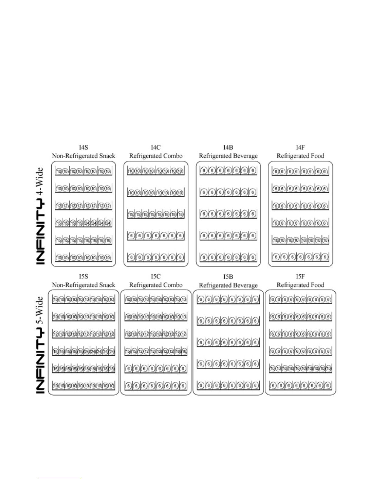
STANDARD COIL CONFIGURATION
Custom configurations available.
Our standard configuration is subject to change without notice to keep up with market and location demand for new
products.
Revision 22 13.10
4
CAUTION: Certain procedures described in this manual require electrical power to the
vending machine. Only trained personnel should perform these functions. Use extreme
caution while performing the procedures marked with the voltage symbol shown here:
CAUTION: Certain procedures described in this manual require a qualified, trained
technician to perform the particular task at hand. These procedures will be marked with the
attention symbol shown here:
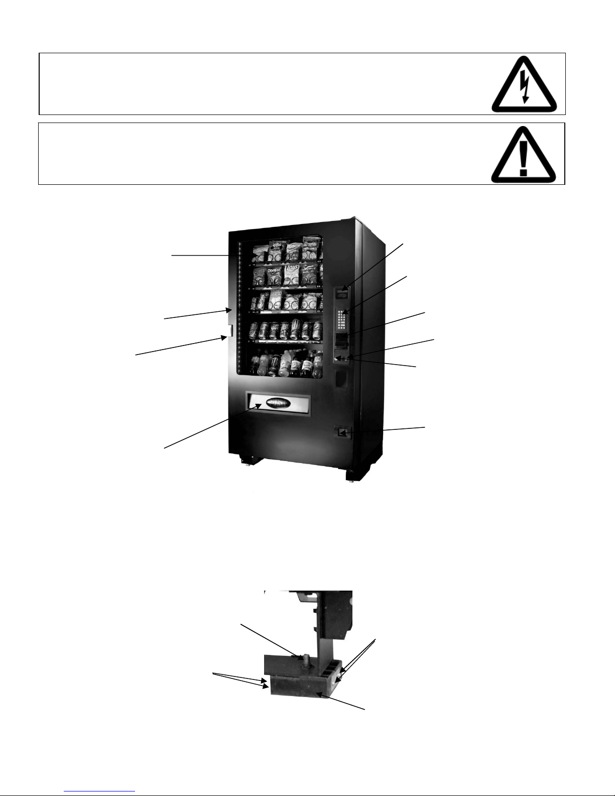
Fig. 1 - Exterior View (I5C 5-Wide Combination Machine Shown)
Display Window
Front Door
Lock
Product Door
Protective shipping guards (Fig. 2) were installed on the leveling legs at the factory. Once the machine is placed near its
final location the protective shipping guards should be removed. To remove the shipping guard, unscrew the leveling leg
from the bottom until the guard is loose – a few turns only. The guard is held together with four phillips head screws and
two brackets. Remove the screws and the guard will split in half for removal.
Fig. 2 – Shipping Guards
LCD Display
Key Pad
Bill Validator
(not installed on all models)
Coin Slot
Coin Return
Button
Coin Return
Door
Leg Leveler
Screws
Revision 22 13.10
Screws
Protective Guard
5
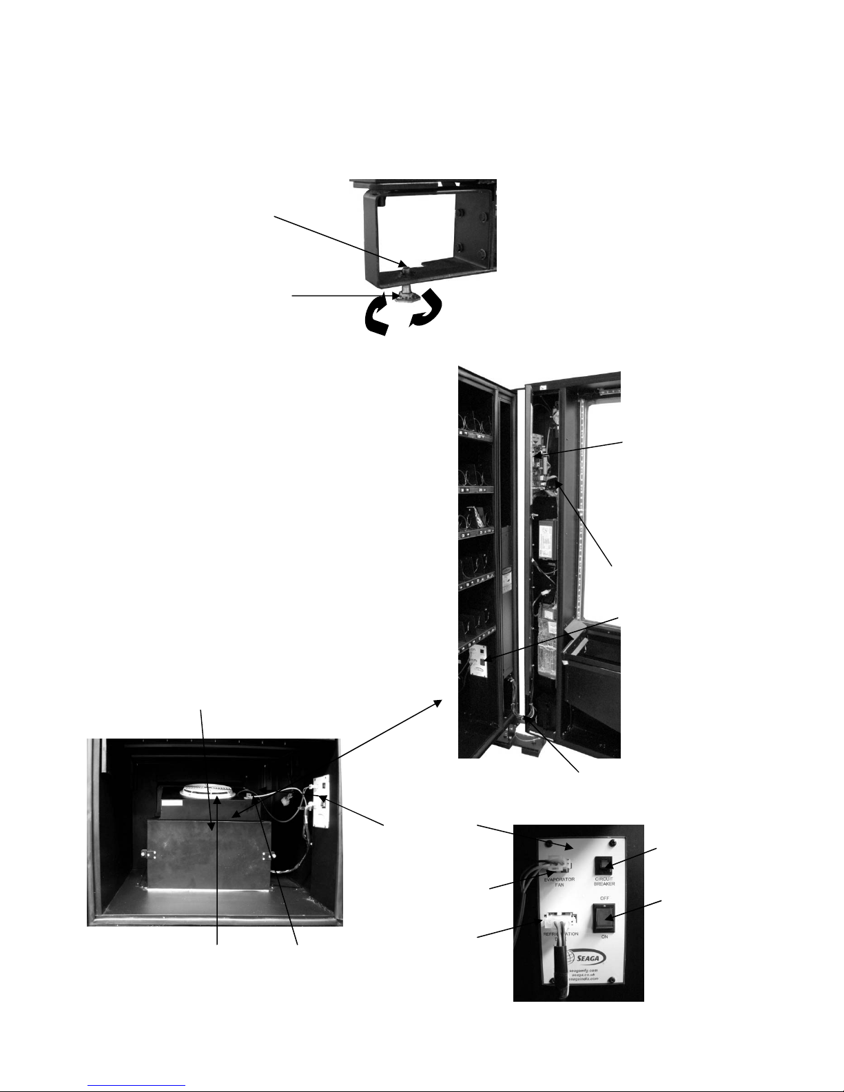
Now place the machine into its final location. Using a level on the top of the machine, adjust the leveling legs for proper
level both side to side and front to back. A good point to keep in mind is the shorter the leveling legs are kept to achieve
proper leveling, the more stable the machine will be.
Proper leveling is also necessary to allow easy opening and closure of the vending machine door and to insure proper
vending operation.
Fig. 3 - Leg Levelers
Use wrench here
to adjust
Fig. 4 - Interior View
Refrigerated model, modular
refrigeration unit.
Evaporator Fan
Revision 22 13.10
Leg Leveler
Control Board
and Service
Mode Button
Display Board
Power Switch
Door Wire
Harness
Control Panel
Circuit Breaker
Reset Switch
Evaporator Fan
Wire Harness
Power Switch
Refrigeration
Wire Harness
Temperature
Sensor
6
SECTION 2 INSTALLATION
CAUTIONS
Your vendor is intended for indoor use only.
Excessive heat, cold or humidity levels will void your warranty; install only in climate
controlled, indoor environments. For indoor machines the temperature range must be no
higher than 32°C/90°F and no lower than 10°C/50°F with a relative humidity (Rh)level of
no greater than 40%.
Your vendor must be set on a level, well-supported location.
Always unload vendor before transporting it.
Remove all wire ties and protective sheeting prior to vending.
CAUTION!
It is important that this machine is hooked up to the proper voltage. Verify the voltage
before connecting the machine to a wall outlet.
CAUTION!
Different countries may have different power arrangements. Insure that the machine is
properly grounded before operating.
CAUTION!
If the power cord is damaged, it must be replaced by the manufacturer, authorized service
agent or a similarly qualified person to avoid electrical hazards.
ATTENTION!
This vending machine is very heavy. Ensure that sufficient personnel are available for
lifting or transporting the machine. Use proper lifting procedures and equipment.
CAUTION!
Certain components of this machine are sensitive to static electricity. Precautions for
handling sensitive devices should be observed when handling these items.
ATTENTION!
Refrigerated models need air flow. Leave at least 6” (15 cm) between the back of the
vending machine and the wall. Condenser cooling air is taken in the bottom and
exhausted out the back of the machine. Clean the condenser once every two weeks or
more often for dusty or dirty locations.
Revision 22 13.10
7
DOOR CLEARANCE
Allow 7” (18 cm) of clearance on the right side of the machine for the door to open and extend past the cabinet side. See
also the clearance requirements in Section 2 for refrigerated units.
LOADING PRODUCTS
To present your product in as an attractive and professional manner as possible, do not load any damaged items, and
make sure items are facing forward for easy identification by your customer.
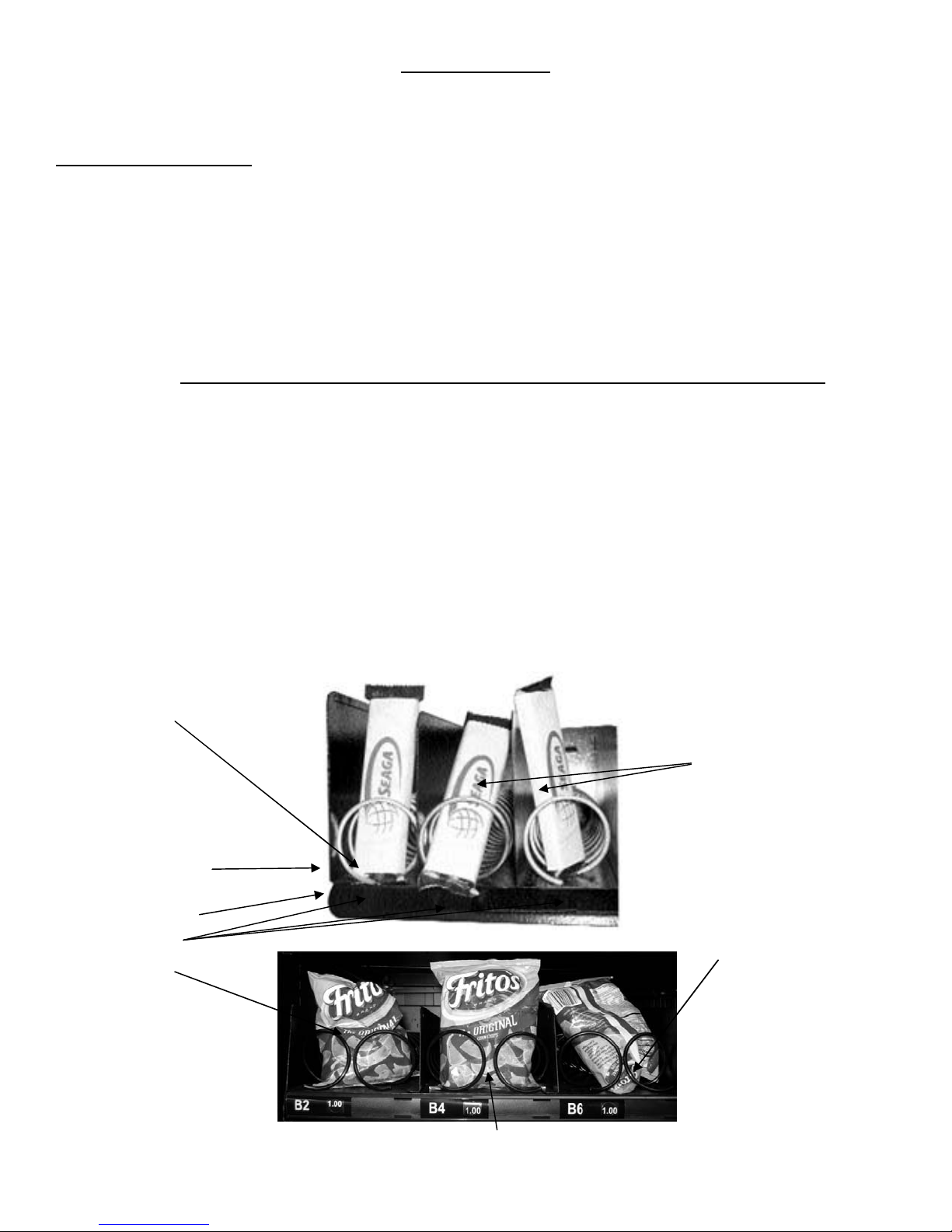
Note: The size of the item being vended must be larger than the Helix Coil, but smaller than the Product Column to vend
correctly. Never force an oversized item into the Helix Coil or Product Column, nor attempt to vend an item that is smaller
than the Helix Coil as this will create problems and deter customers. (Fig.5)
1. To Load Product:
A.) Push down and hold the release latch located on the right side of the tray and slidel the desired Product Tray
toward you, all of the way forward. Product Tray will tilt down or can be removed and placed on the floor or a
table. Note: Pull out only one (1) Product Tray at a time. Beverage trays do no t tilt for lo adi ng !
B.) Place product in proper size Helix Coil. Note: Bottom of product must
rest on the Product Tray and not on the Helix Coil. (Fig. 5) Load each
Product Chute from front to back. Note: Do not leave any spaces between items.
C.) Once Product Tray is loaded, lift the front of the tray to level and push it
back in. Repeat above steps until all Product Trays are fully loaded.
D.) After loading the product, if you have removed the tray to do so, place the
Tray in the cabinet by aligning the wheels in the guide rails. Clear the wire harness
To the side so that it is not interfering with the tray below.
To increase the length of the Helix Coil, plastic Product Pushers can be snapped on the end. Product Pushers can be
purchased from Seaga’s Customer Care team.
Note: We suggest that you always partially fill the vendor with product and perform at least five (5) test vends. Test vends
can be performed easily by entering Service Mode and using the Diagnostics/Motors to select the selection to test.
Fig. 5 – Loading Helix Coils
Correct – load
product
between Helix
Coils, resting
on the product
tray.
Helix Coil
Product Tray
Columns
Incorrect
Revision 22 13.10
Correct – load product between coils,
resting on the product tray.
8
Incorrect
Incorrect
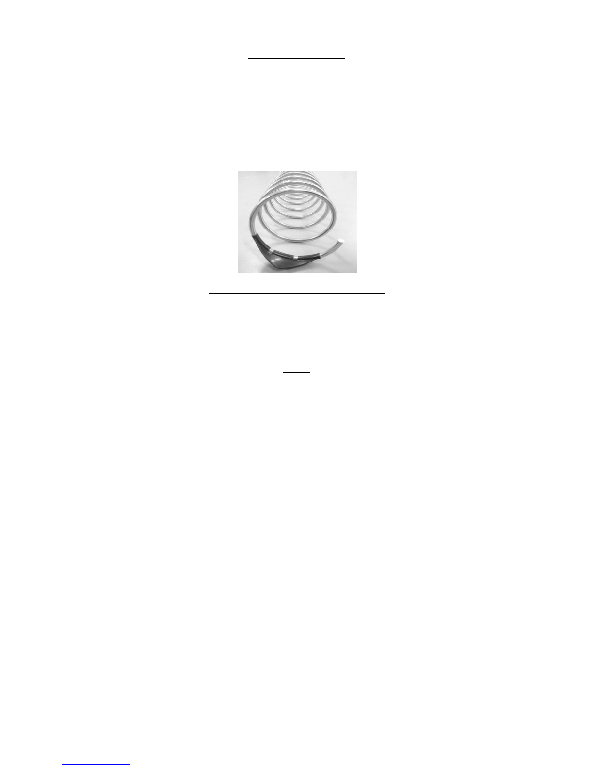
PRODUCT PUSHERS
Product pushers assist in moving the top of the product forward while it is being vended on the bottom, helping it fall
smoothly from the shelf. Product pushers are also good for products that have the wrapper flaps on the ends of the
package. Packaging such as this benefits from the extra momentum from the product pushers to keep the flaps from
hanging up the product on the spiral. Product pushers are available from Seaga’s Customer Care and Parts department.
The pusher is installed approximately ½ inch (1.5 cm) from the end of the coil with the tab extending forward (see Fig. 6).
Locate the pusher in its proper position, hold it against the coil wire and push the semi-circular part around the coil wire.
Note: Boxed items will not need a product pusher.
Figure 6 – Product Pusher Installation
LOADING BAGGED OR BOXED ITEMS
Vending small bagged items in the 8 or 10 selection trays can be a problem when the products are not loaded properly.
The flap edges of some products may get trapped under the spiral and cause the product to “hang up”. It is recommended
that the bottom flap of this type of packaging be folded forward and up (Fig. 5) next to the product when loading. This type
of packaging also lets the product settle to the bottom, so using the wider spirals is also recommended.
LOCK
Your vendor has one Lock, more commonly known as T-handle lock. To unlock the front door, insert key and turn
clockwise ¼ turn. When unlocked the ‘T’ of the Lock will pop out from its base. Turn the ‘T’ counter clock wise to unlock
the door. To Lock the door, firmly close the door and turn the ‘T’ handle clockwise 1 to 2 times and then pull on the door to
test that the lock has engaged. If so, then push the ‘T’ inside the Lock to lock the door and remove the key. Note: Do not
over-tighten when locking – this could strip the threads and damage your machine.
Revision 22 13.10
9

REFRIGERATION
If you purchased a refrigerated model, please see special information throughout the manual regarding refrigeration,
settings and other information. The refrigeration system consists of a Compressor, Relay Circuit, Accumulator,
Condenser, Condenser Fans, Evaporator, Evaporator Fan and Air Duct. The entire refrigeration system is modular and
has a separate internal power cord, which is plugged into the panel provided at the lower area below the bottom tray. The
power switch has to be turned ON in order to start up the refrigeration system. There is a door switch that controls the
refrigeration system ON and OFF condition. When the door is opened, the door switch is not depressed and the
refrigeration system shuts OFF. When the door is closed, the switch is activated and the evaporator fan starts turning.
There will be a delay of a few seconds before the compressor starts running after the door closure.
There is a vent on the cabinet back to blow the air from condenser. The inlet vent is at the bottom of the cabinet in front of
the condenser. The condenser has to be cleaned regularly. The recommended frequency is once every two weeks.
There are 2 thumb screws around the front of the refrigeration module that have to be unscrewed in order to remove the
front door of the refrigeration module. This will provide the access to the condenser. Using a vacuum cleaner or a brush,
clean the lint in between the condenser fins. Note: Be careful not to bend the fins – this could restrict airflow and damage
your machine.
The compressor and the relay circuit, condenser fan motor and drain pan can be accessed in the same manner by
removing the front door. The refrigeration system has to be unplugged and the module has to slide completely outside in
order to gain access to these components.
NOTE: When moving the vending machine, care must be taken to never tilt the unit more than 20° in any
direction. After moving, DO NOT plug the unit in to power so that the compressor system oils are allowed to
settle. Failure to heed these instructions can cause severe damage to your vending machine and void your
warranty.
Revision 22 13.10
10
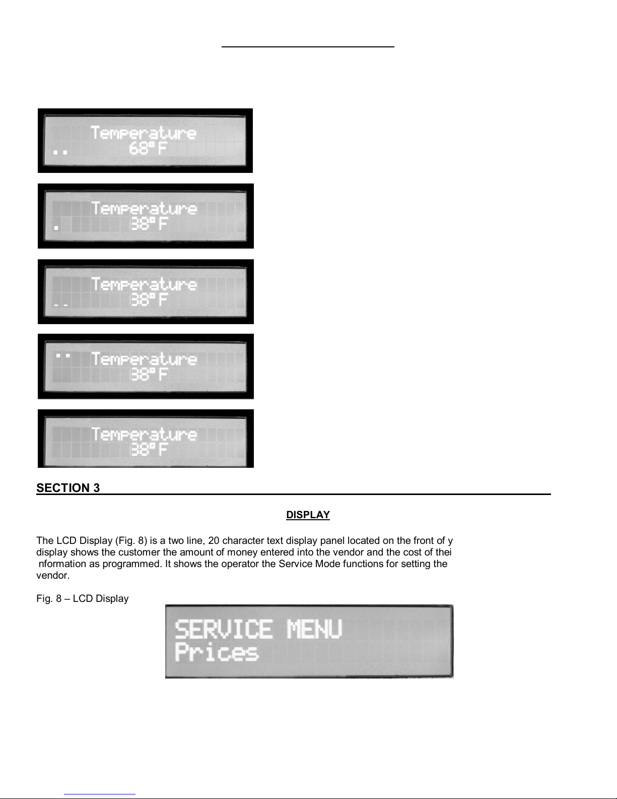
REFRIGERATION STATUS DISPLAY
Use the “10” key on the Keypad to display the following indications of the refrigeration system on the LCD Display:
Figure 7 – Refrigeration Indicators on LCD Display
Delayed Start Mode – door switch is not being
engaged; compressor will not start in this mode.
Cooling Mode – Door switch is engaged and
compressor is active. The machine is cooling but not
yet at operating temperature.
Defrost Mode – Machine is in defrost cycle. Defrost
cycle time can be set using the Advance menu option
Auto-Defrost in Diagnostics.
Zone 1: Zone 1 is active on the machine. Your SP
series machine should only use Zone 2. Shut off Zone
1 in the diagnostics mode using the Advanced
submenu.
If there are no indicators on the display, the machine is
at the operating temperature.
SECTION 3 OPERATION
DISPLAY
The LCD Display (Fig. 8) is a two line, 20 character text display panel located on the front of your vending machine. The
display shows the customer the amount of money entered into the vendor and the cost of their selection among other
information as programmed. It shows the operator the Service Mode functions for setting the various functions of the
vendor.
Fig. 8 – LCD Display
Revision 22 13.10
11
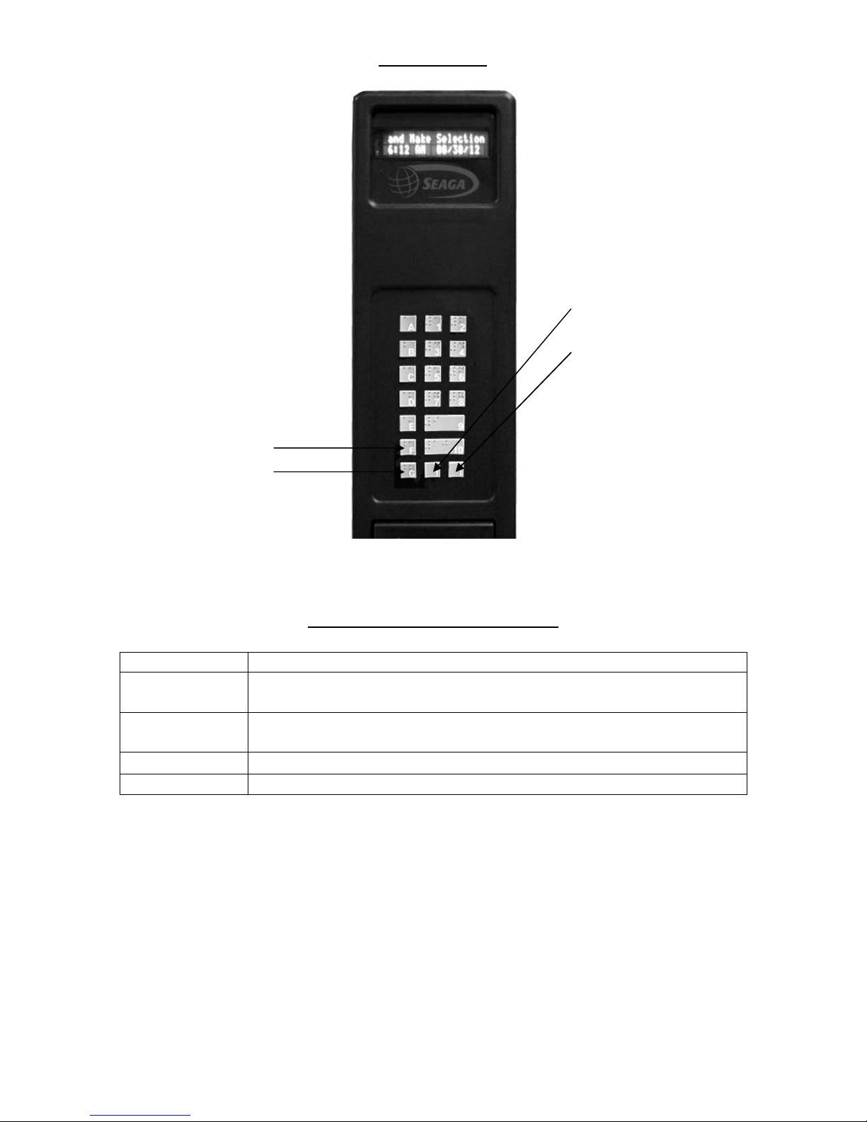
F=ENTER
SERVICE MODE
↑= NEXT OR
INCREASE
↓= PREVIOUS OR
DECREASE
Revision 22 13.10
G=EXIT
Navigation of the Service Mode Menu
BUTTON FUNCTION
↑ Button
↓ Button
F Button
G Button
This key is used to increase a numeric value, or move forward through the
various service mode functions.
This key is used to decrease a numeric value or move backwards through
the various service mode functions.
This key is used to confirm, accept, or ENTER into a service mode function.
This key is used to EXIT the service mode or a service mode function.
12
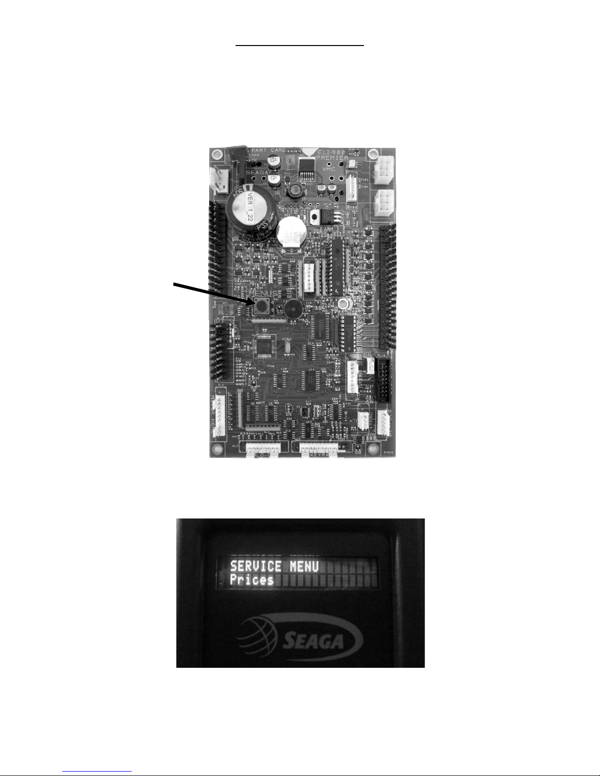
ENTERING SERVICE MODE
To enter into service mode, open the vendor door and Press the Menus Button (Fig. 10). After pressing the Service mode
switch the controller will beep twice and the display will change to show “Service Menu” on the first line and “Prices” on
the second line (Fig. 10). At this time you can use the keypad on the front of the machine to move through the various
service mode MENUS.
Fig. 9 - Service Mode Button
MENUS Service Mode
Button
Fig. 10 – LCD Display while in Service Mode. The Prices menu is the first sub-menu.
Revision 22 13.10
13
TO EXIT SERVICE MODE
The controller will remain in service mode as long as the user keeps using the keypad to move through the various
service mode MENUS. The controller will automatically exit service mode and return to sales mode if any of the following
occur:
1) The user is inactive for more than 1 minute
2) The user presses the EXIT key (G).
After exiting the service mode, the installed firmware version shows on the display for three seconds, then the controller
will revert to sales mode.
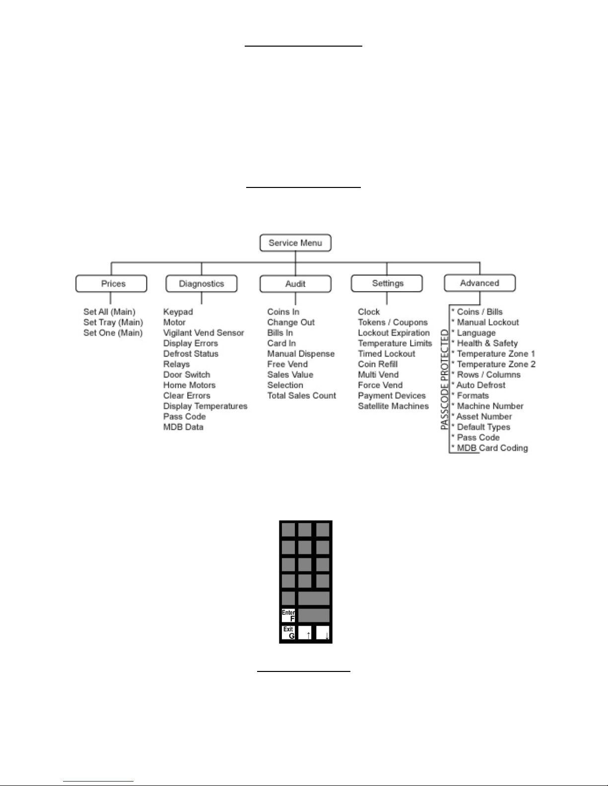
SERVICE MODE MENUS
The chart below shows the sub-menus while in Service mode:
In the following instructions, refer to the drawing of the four button navigation key drawing on the left side of the page.
Follow the arrows, paying attention to the navigation instructions (F), (G), (↑) and (↓)
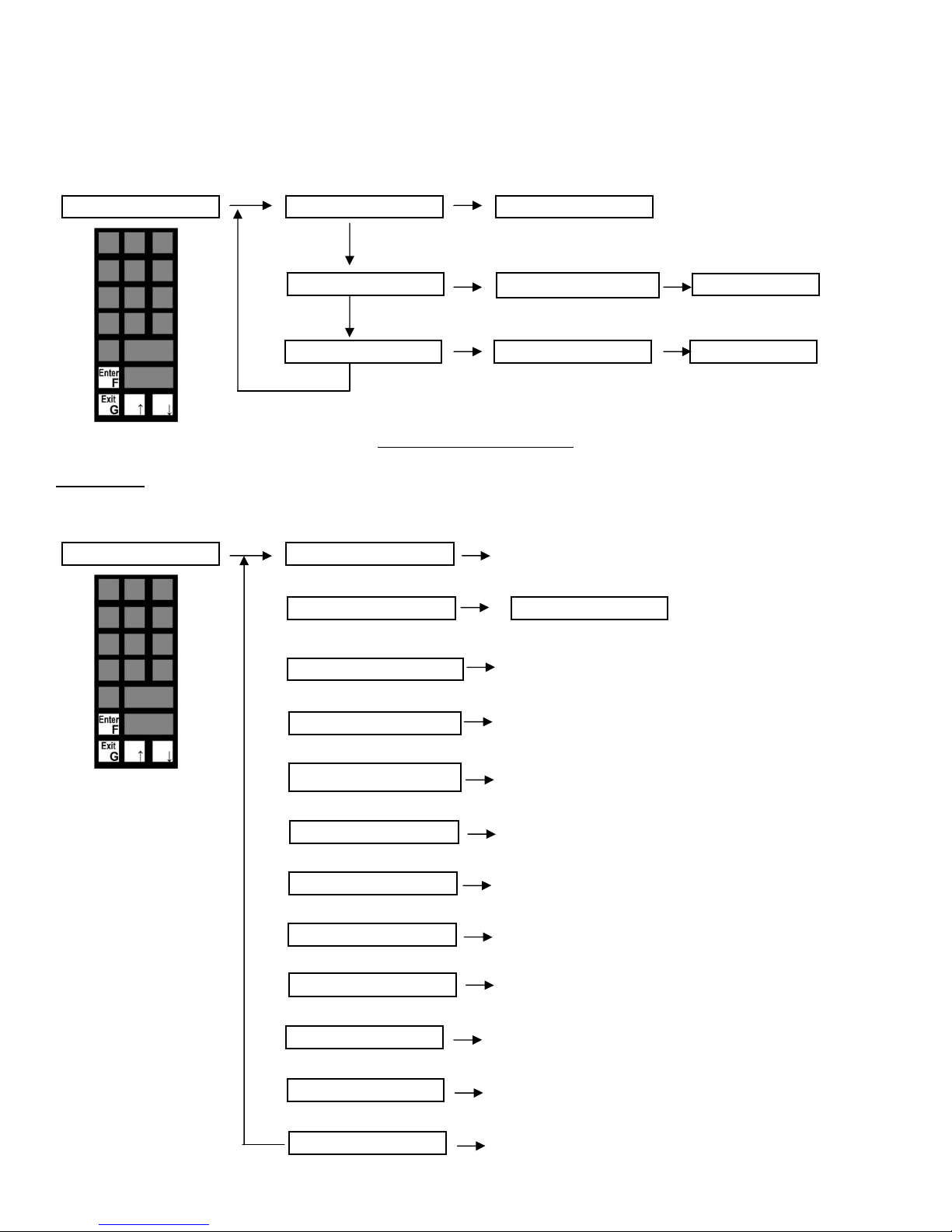
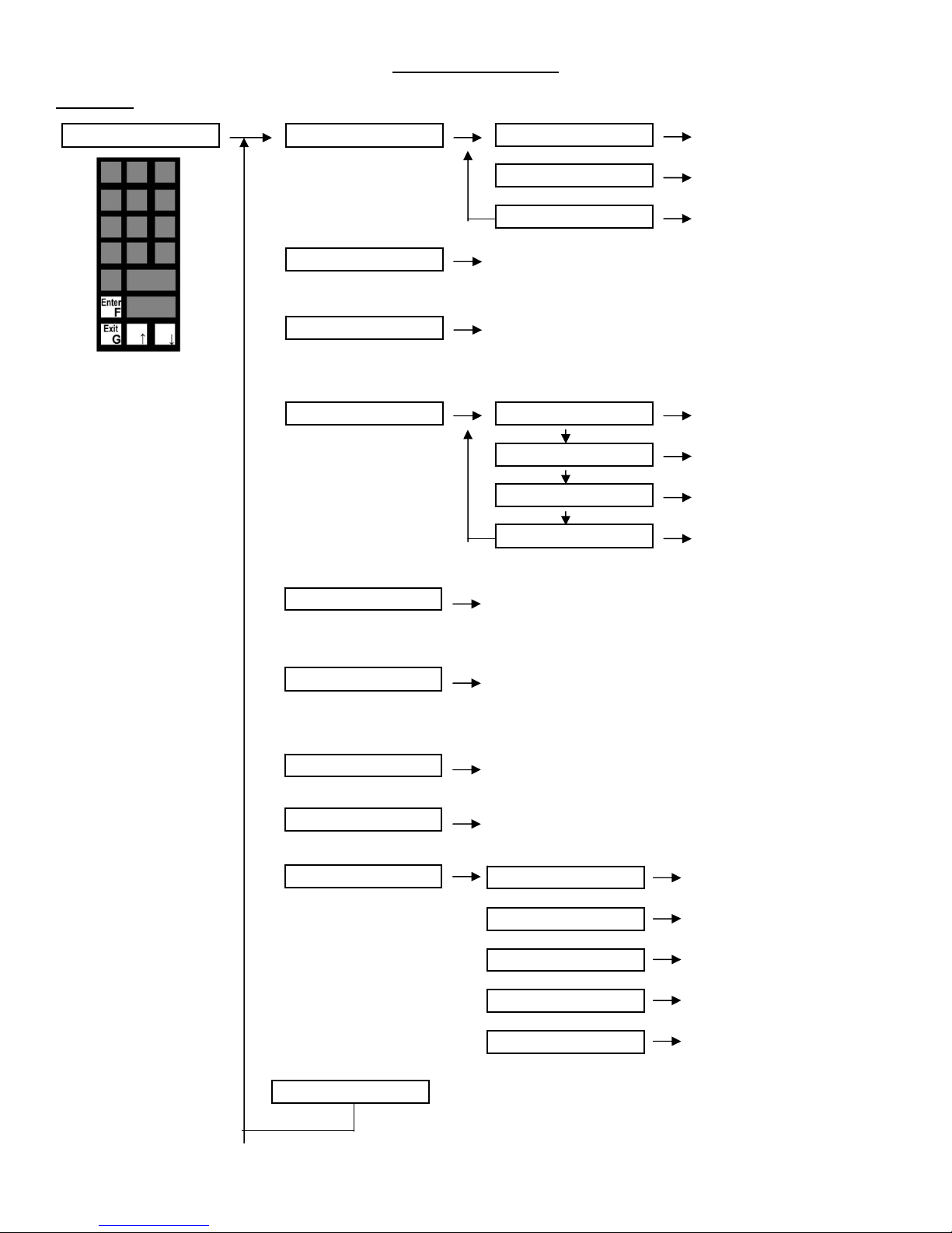
PRICES SUB-MENU
The Prices sub-menu allows you to set prices in three different ways – Set ALL, Set ONE, Set Tray. Set ALL will allow you
to set all of selections in the machine to the same price. Set ONE will allow you to set one individual selection of your
choosing. Set Tray will allow you to set an entire tray to the same price.
Revision 22 13.10
14
Using these available options will save you time – if the majority of your price is, for example, set at $1, use the Set ALL
(F)
(F)
(F)
(F)
(F)
(F)
(F)
sub-menu to set all prices to $1. You can then go back and set individual prices for certain selections as needed.
In order to enter the price, Press the corresponding number. For example, if the Price of a Selection is $0.75, then Press
“7” and “5”. Press F to accept the value; G to exit to the main menu. Note: Discount pric es can only be s et using a S eaga
Smart Card.
1. Prices 1. 1 Set ALL (Main)
(F)
(↓)
1. 2 Set Tray (Main) 1.2.1 Enter Tray Letter
(↓)
1. 3 Set One (Main)
(F)
1.1.1 Enter Price
(F)
(F)
1.3.1 Enter Row/Column 1.3.1.1 Enter Pric e
Press (F) to complete
1.2.1.1 Enter Price
(↑)
Press (F)
to
complete
Press (F)
to
complete
DIAGNOSTICS SUB-MENU
Diagnostics - The Diagnostics menu is used to test various features of the machine. Certain critical features of the
machine are protected by a pass code provided to the operator to prevent inadvertent modifications to the machine.
2. Diagnostics 2. 1 Keypad
(F)
2. 2 Motor
2. 3 Positive Vend Sensor
2. 4 Display Errors
2. 5 Display Defrost Status
2. 6 Relays
2. 7 Door Switches
2. 8 Home Motors
2. 9 Clear Errors
2. 9 Display T emps
2. 10 Passcode
Revision 22 13.10
2. 12 MDB Data
(↓)
(↓)
(↓)
(↓)
(↓)
(↓)
(↓)
(↓)
(↓)
(↓)
(↓)
(F)
Test any key on the keypad. Note: you
must let this function time-out to exit.
(F)
2.2.1 Enter Row/Column
Note: you must let this function time-out to exit.
(F)
Tests the vend sensor – Beam Clear or Beam
Blocked message displayed
(F)
Displays the Errors Logged on the VMC
(F)
Tests the Defrost Status and displays information
on Time of Defrost, Duration and No. of intervals
per day. Fig (12)
Tests the components connected via Relays –
ON/OFF
Tests the status – ON/OFF – 2 DOOR
SWITCHES
Test the motors, if they are home and counts the
total number of motors in the machine (Fig. 12)
Clears all errors
Display Temperatures of Zone 1 and
Zone 2
Display/edit the PassCode
Display MDB Data
15
Tests Individual Motors
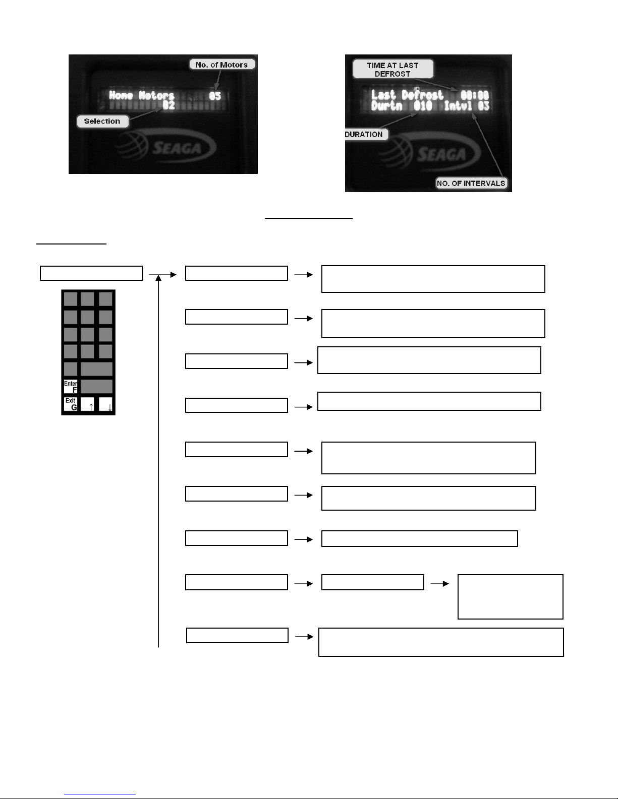
Fig. 11 Fig. 12
AUDIT SUB-MENU
AUDIT MENUS -The Audit Menu is used to track the machine operation in all aspects but not limited to the transactions.
3. Audit 3. 1 Coins In
(F)
3. 2 Change Out
3. 3 Bills In
3. 4 Card In
(↓)
(↓)
(↓)
(↓)
(F)
Displays Total Amount of Coins inserted during
transactions
(F)
Displays Total Amount of Coins dispensed
during transactions
(F)
Displays Total Amount of Bills inserted during
transactions
(F)
Displays Total Amount of Card Transaction
Revision 22 13.10
3. 5 Manual Dispense
(↓)
3. 6 Free vends
(↓)
3. 7 Sales value
(↓)
3. 8 Selection
(↓)
3. 9 T otal Sales Count
(F)
Displays total Amount that is dispensed
manually during servicing of Coin Mechanism
(F)
Displays Total Number of Free Vends
(F)
(F)
(F)
16
Displays Total Sales Cash Value
3.8.1 Enter Row/Column
Displays Total sales for this machine. This number is
cumulative – a running total.
Displays Total no. of
vends on that
individual selection
(F)
(F)
(F)
(F) (F)
(F)
(F)
(F)
(F) (F)
(F) (F) (F)
(F)
(F)
(F)
(F)
(F)
(F)
(F)
(F)
(F)
SETTINGS
4. Settings 4. 1 Clock
- This menu is used to Setup the features of the machine.
4.2 T okens/Coupons
4. 3 Lockout expiry
4. 4 T emperature Limits
4. 5 Timed Lockout
4. 6 Coin Refill
4. 7 Multivend
4. 8 Forced Vend
4. 9 Payment Devices
4.10 Satellite Machines
SETTINGS SUB-MENU
(↓)
(↓)
(↓)
(↓)
(↓)
(↓)
(↓)
(↓)
(↓)
4.1.1 Time
(↓)
4.1.2 Date
(↓)
4.1.3 Day of Week
Set Time on the
machine
Set Date on the
machine
Set Day of the
week –
ON/OFF
Set Time and Date for
the Lockout settings to
1 – Sunday
2 – Monday
3 – Tuesday
4 – Wednesday
5 – Thursday
6 – Friday
7 - Saturday
expire
4.4.1 Zone 1 Upper
4.4.2 Zone 1 Lower
4.4.3 Zone 2 Upper
4.4.4 Zone 2 Lower
Setup the Upper Limit
for Zone 1
Setup the Lower limit
for Zone 1
Setup the Upper
Limit for Zone 2
Setup the Lower limit
for Zone 2
Enables you to set two lock-out time durations per
day. Ensure your date and time settings are
correct prior to using this function.
Shows the count of the coins of each denomination
being inserted. Manual Dispense of the Coin mech is
enabled in this menu option (Fig. 13). Depending on
the model of changer installed, the amount will vary.
ON/OFF
ON/OFF
4.9.1 Coin Changegiver
4.9.2 Bill Reader
4.9.3 Card Reader #1
4.9.4 Card Reader #2
4.9.5 Executive
Enabled/Disabled
Enabled/Disabled
Enabled/Disabled
Enabled/Disabled
Enabled/Disabled
Revision 22 13.10
17
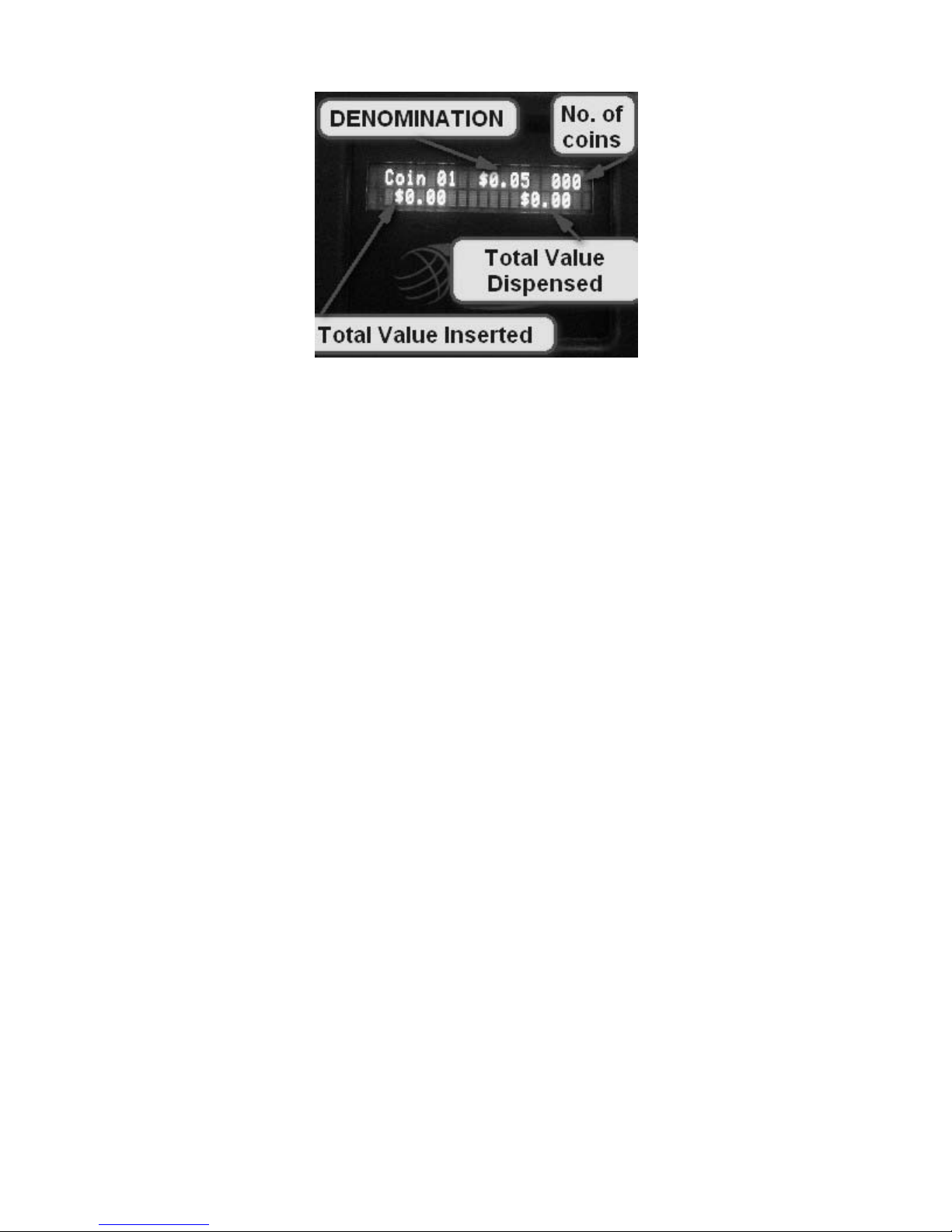
Fig. 13
*Total Value Dispensed and Total Value Inserted is a cumulative total for each coin.
Revision 22 13.10
18
 Loading...