

Page 1
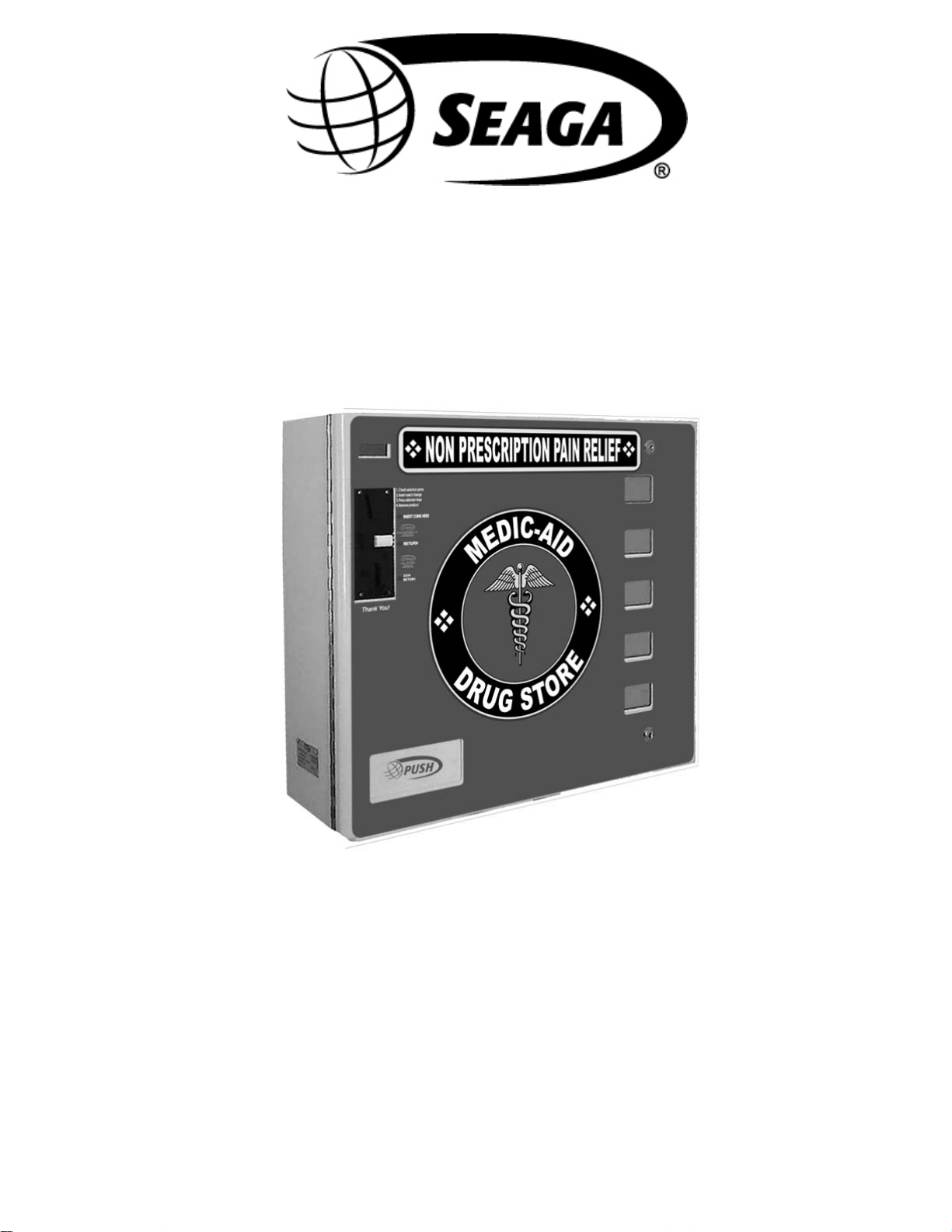
SL5000
Rev. 2012.02.27
Operator’s Manual
1
Page 2

INTRODUCTION
Congratulations on the purchase of your new SL5000. This SL5000 has been designed to give you many years of dependable
service. It requires little maintenance and is e asy to se t up and operate.
READ THIS MANUAL COMPLETELY
Your SL5000 is designed to operate simply and reliably, but to take full advantage of your vendor, please read this owner’s manual
thoroughly. It contains important information regarding installation and operations, as well as a brief trouble-shooting guide.
EQUIPMENT INSPECTION
After you have received your machine and have it out of the box, place it on a secure surface for further inspection. Note: Any
damages that may have occurred during shipping must be reported to the delivery carrier immediately. Reporting damages and the
seeking of restitution is the responsibility of the equipment owner. The factory is willing to assist you in this process in any way
possible. Feel free to contact our Customer Care Department with questions you may have on this process. It is important that you
keep the original packaging for your vending machine at least through the warranty period. If your machine needs to be returned for
repair, you may have to purchase this packaging if it is not retained.
Once your have your vendor located, we suggest that you keep this manual for future reference, or you can view this manual online
at www.seagamf g.com
designed to help you quickly identify a problem and correct it.
. Should any problems occur, refer to the section entitled “COMMON QUESTIONS AND ANSWERS”. It is
For Service and Cust omer C are:
8:30 a.m. - 4:00 p.m. CST. Mon thru Fri
815.297.9500 ext 160
815.297.1758 Fax
email: c ustomercare@s eagamfg.com
Seaga Manufacturing, Inc.
700 Seaga Drive
Freeport, IL 61032 U.S.A.
seagamfg.com
IM P ORTANT NOTICES
Your vendor (s) are intended for indoor use only
Your vendor (s) must be set on a l ev el, well-supported locati on.
Always unload vendor before transporting it.
Do not load your vendor wit h disfigured or damaged product.
For Service and Cust omer C are:
9:00 a.m. - 5:30 p.m. Mon thru Fri
+44(0)1492 874010
+44(0)1492 874644 Fax
email: [email protected]
Seaga UK Ltd.
Unit 8, Caebach, Off Builders Street
Llandudno North Wales LL30 1DR
seaga.co.uk
Rev. 2012.02.27
2
Page 3
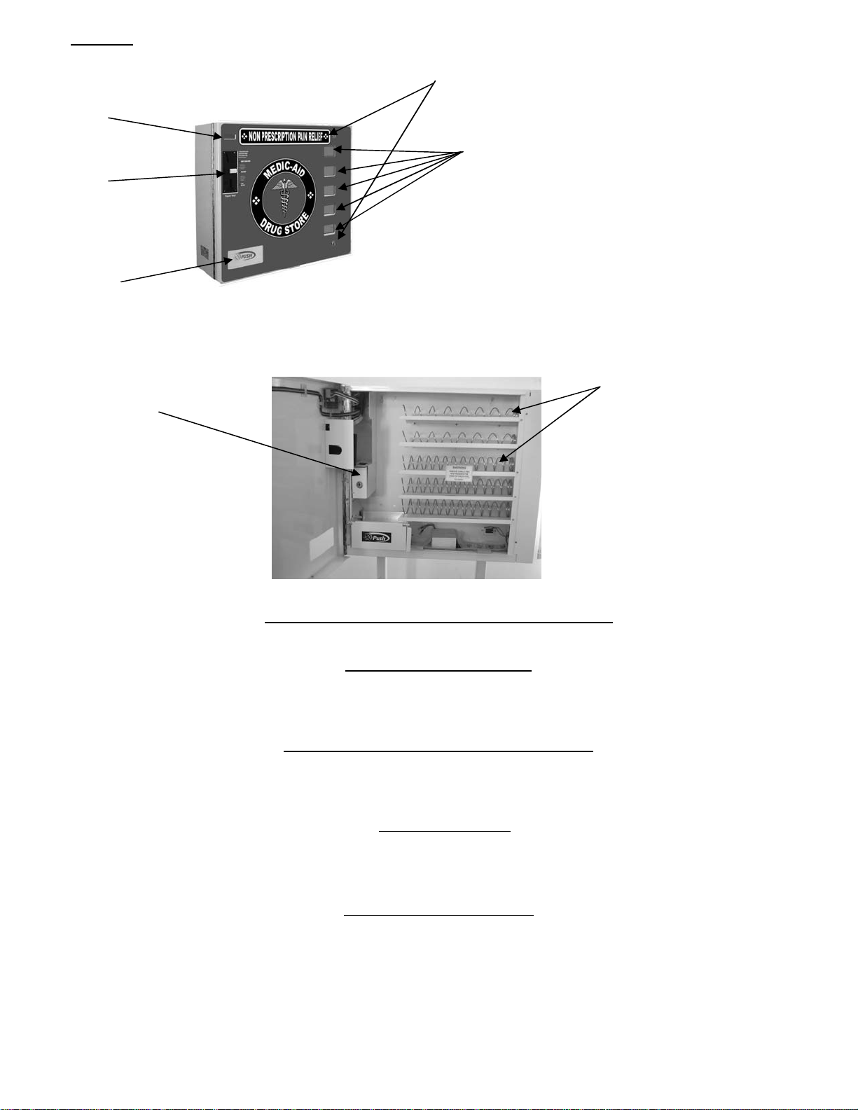
Section 1 Brief Descript io n o f your SL5000
play
LCD
Dis
Locks
Selection Pads
Coin Validato r
Vend Area
Fig.1
Coils
Coin Box
HOW TO LOCK & UNLOCK THE DOOR OF VENDOR
Your SL5000 has 2 locks. T o open the door, unlock the top and bottom locks by t ur ning the keys clockwise.
ELECTRICAL CONNECTION
The SL5000 may be driven by a 12-volt battery or via a permanent 12 VDC supply obtained through an AC/DC
adapter. The S L5000 incorporates a M ulti Functi onal Controller Boar d with a range of f eatures such as 5 indiv idual
selections and multiple coin handling in a compact size.
PRODUCT SELECTION PRICING AND LA B E LS
Product selection is made using the 5 selection pads (see phot o above). The prices can be set by ent eri ng the Service
Mode.
DELIVERY SYS TEM
The delivery system of your SL5000 incorporates a Selection Pad, an LCD Di splay and helix coils. The customer
inserts money i nto the coin slot and enter s their selection on the Selec tion Pad; the selected Driv er Motor turns the
helix coil and vends the produc t.
KEYPAD AND LCD DISPLAY
The Selection Pad has touch-sensitive operation. Light pressure will be necessary to activate the appropriate
motor/helix c oil rel ating to any parti cular shelf. T he Selecti on Pad is used by the custom er to make their selecti on, and
by the operator to set and t est the many functions of the vendor (Fig.1) .
The LCD Display shows the customer the amount of money entered into the vendor and the cost of their selection, it
shows the operator the S ervice Mode function for setting and testing the various functi ons of the vendor.
Rev. 2012.02.27
3
Page 4

BATTERY MODE OF OPERATION
During Batt ery mode, the machine operates in ‘S leep Mode’. This means that when the m achine is not in operati on
(between vends), it will automati cally shut down in ord er to save batter y power, thus prolongi ng the life of the battery.
During ‘Sleep Mode’ the machine display turns off its left hand digit (unless there is a value great er than 0 present) and
the machine monitors to see if a coin has been inserted or a button pressed in order to ‘wake-up’. The following
conditions will ‘wake-up’ the machine from ‘Sleep Mode’.
1. Coin Insertion
2. Selection Butt on P r ess
3. Black (Reset) B utt on P r ess
4. Red Service Butt on Press
On Wake-up the machine will only go back to ‘Sleep Mode ‘ under the following c onditions:
1. Directly after a vend has been made (Unless there is excess credit present in which case
the machine will wait a further 60 seconds before going t o sleep].
2. After 30 seconds after a selecti on has been pres se d and the machine contains product.
3. After 20 seconds after a selecti on has been pres se d and the machine does not contain a
product.
4. After 5 seconds if an invali dated coin has been inserted and the machine c ontains product.
5. After 60 seconds after a coi n has been inserted and validated.
6. After 5 seconds if the machi ne is completely empty.
7. After 5 seconds after if the machine is out of order.
8. After 5 seconds after the black ( reset) button is pressed and the machine is empty.
9. After 20 seconds after the black (reset) button is pressed and the mac hine c ontains product.
10. After 8 seconds after leaving service mode
These values are extended each time a selection is pressed or coi n is i nsert ed to a maximum of 60 seconds.
When the machine goes to sleep, the following messages are display ed under set c onditions
When Awake When Asleep
i. 00.00 – 09.00 0.00 – 9.99 (Decimal point s al ways on)
ii. 10.00 – 99.99 10.00 – 99.99 (Decimal point s al ways on)
iii. Free Fr.ee (Decimal points always on)
iv. Test Te.st (Decimal points always on)
v. Out of Ordr F-Er (Fatal Error set)
vi. - - .- - -.- - (Decimal point always on)
When the vending machine detects that a battery is low an error code will be displayed (51). This code will r emain on
display until the battery has been replaced and the black r eset button has been pressed.
When the vending machine detects that a battery is dead, the mac hine wi ll permanently turn itself off .
Section 2
SERVICE MODE
In this dedi cated version of software the VMC is l imited to 5 colum ns, each with a dedi cated “negativ e counters”
to count down the stock i n each c olum n. When t he cor respondi ng ne gative counter r eaches zero the selec ti on i s
shown as “Sold Out”. The capacit ies f or each col umn are set wit h the “nC“ menu opti on. If all columns are sold
out coin acc eptance is i nhibit ed.
The negative c ounter s can be reset using the “ A” or “B” but tons:
“A” But ton – unc onditi onall y resets ALL counter s to m axim um capacit y. The operat ion is conf irm ed wit h a long
bleep and ALL r-ld on the display.
“B” Button – only r esets any counters that are zero (i.e. fully vended)to their maximum capacity. Counters that are not fully
vended are not changed. The operation is confirmed with a long bleep and r-ld on the display.
Operation
The operation of the machine can be adjusted by entering serv ice mode by pressi ng the red button on the VMC
circui t boar d and t hen ac cessi ng th e appr opri at e oper ation. Pric e sett in g, coin val ue sett ing, and v end-c redi t cri teri a
can be rea d and a dju sted f rom here. T he use r can al so p erfor m test s on th e machi ne t hrou gh thi s m ode. Not e: an y
Credit will be cancelled on entry to Service Mode.
Rev. 2012.02.27
4
Page 5

1. Enter S er vice Mod e by pres sing th e Ser vi ce Button on th e VMC Cir cui t boar d.
On entry to Service Mode, up to 8 Error Codes may be displayed. These can be cleared using the Clear Errors menu option.
Error Code Display Er.** where ** is the err or number
2. Each Serv ice Code c an then be acce s s ed by r epeat pressing of the Service Butt on
Pressing Service Button (AUDIT) Displays Au.-Pressing Service Button (PRICE SETTING) Displays PS.--
Pressing Service Button (COIN VALUE SETTING) Displays Cn.-Pressing Service Button (CONTROL WORD SETTING) Displays Ct.**
Where ** is the current word
Pressing Service Button (SOUND On/Off) Displays So.0*
Where * is the current state
Pressing Service But ton (STOCK MOD E On/Of f)
OR
SL5000 – (NEGATIVE COUNTERS)
Displays St.0*
Where * is the current state
(0 or 1)
OR
Pressing Service Button (TEST MODE) Displays tE.-Pressing Service Button (TEST ALL MOTORS) Displays AL.-Pressing Service Button (CLEAR ERRORS) Displays CL.-Pressing Service Button (FACTORY RESET) Displays Fr.-Pressing S er vice But ton (EXIT) Machine goes to Sleep
3. Service M ode can be exited by stepping through all t he menu opti ons usi ng the Service Butt on, or automatically if
there is no activity for 30 seconds. On Exit the software version number is displayed as u2.10
Audit
Withi n Serv i ce Code AU (Au dit ) rea din gs can be tak en f rom the Di spl ay wit h r egar ds to c as h tak en, a nd n umber of
products vended. The foll owing details c an be obtained on th e Display .
1 Total Cash Taken (up to 9 999.99)
2 Total Prod uc t Vended (up t o 9999)
3 Indi vidual Produ c t Vended (from each s election) up t o 999
4 Total Cash Out as change (up to 9999.9 9) #
Press the Red Service Button repeatedly till the LCD Displays Au.
You are now in Audit Mode
Press Selection 1 to rev eal the total cash ($) a nd (c) taken.
Displays 88.88 for 0.75 seconds before showing the cash values: Displays ****and--. **
Press Selection 2 to rev eal the total product vended Displays ****
Press Selection 3 to rev eal the in dividual product vended
The display scrolls through each selection di s playing the qu antity vended 1.*** to 9.***, then A .*** through to F.***
and then 0.** * for selections 1 to 16 resp ec tively. Press any selection key to end this s equence imm ediately.
Retur ns to Au- at en d of rout i ne.
Press Selectio n 4 to clear all the Au dit data Displays Clr
Rev. 2012.02.27
5
Page 6

E
Press Selection 5 to :
show the total cash OUT($) and (c) # Displays ****and--. **
then negative count er values (selectio n n, count xx) Displays 0n.xx
then the “no load” bat tery voltage Displays **.*0
then the “under load” battery voltage Di s plays * *.*0
Press Serv ice Button to scr oll to exit.
Price Setting
Pri ce Setting can be d one by enter in g Service Code PS .
Each s election can be a llocated any price from 00.00 to 9 9 .99 , and is achieved by inserting coins to the vend amount and allocating
that amount to th e desired selection( s).
1 Press the Red Service Button repeatedly until the LCD Displays PS.—
You are now in Price Setting Mode
2 Insert coins to the first desired price (for simplicity set the lowest price first)
Cred it will accum u late on th e di s pl ay. Displ ays **. **
3 Press desired selection button to store displayed credit to that selection – a long bleep and a “Set” display will confirm that the
price has been programmed.
4 Insert additional coins if required and repeat for other selections.
5 Press Service Button to scroll to exit.
Prices may be set from 00.00 to 99.99 (depending upon coin values). The default price setting is 1.00
Coin Value Setting
Coin Value set ting al lows for the changi ng of the individual values for the 6 coin outputs from the Coin Acceptor.
Values can be adjusted from 00.00 to 99.99 or ca n be set as a free vend t oken.
1.Press the Red Service button repeatedly until
Displays
Cn.--
You are now in the Coin Value setting Mode
You first need to set t he value for th e coin
2. Press Selection B utton 1 to increment the --.** Value
Displays 00.**
3. Press Select ion Button 2 to decrement t he --.** Value Displays 00.**
That is the cent/pence value set, now we need the
dollar/e ur o/pound value
4. Press Sel ect i on Butt o n 3 to i ncr em ent the **. - V a l ue Displays
5. Press Sel ect i on Butt o n 4 to d ecrem ent th e **. -V al ue Displays
**.??
**.??
6. Press Sel ect i on B utt on 5 to set the coi n a s a F re e v end
Displays
FrE
Token (pr es sing any ot her k ey reverts to a value)
Now with the value on the display, insert the co in for which the value mus t be assigned
Rev. 2012.02.27
6
Page 7
7. Inser t Req uired Coin unti l it i s accepted and the uni t “bleeps” and displays “Set” to a s sign the value to that coin
8. Repeat ste ps 3 to 7 until all coins are s et.
9. Press Service But ton to exit
Control Word Setting
1. Press the servi ce button repeatedly unt il
Displays Ct. **
(where ** is current value)
You are now in Contro l Word Setting
2. Press Select ion Button 1 to increment the v alue Displays Ct.**
The control word is n ow set
4. Press Service But ton to exit
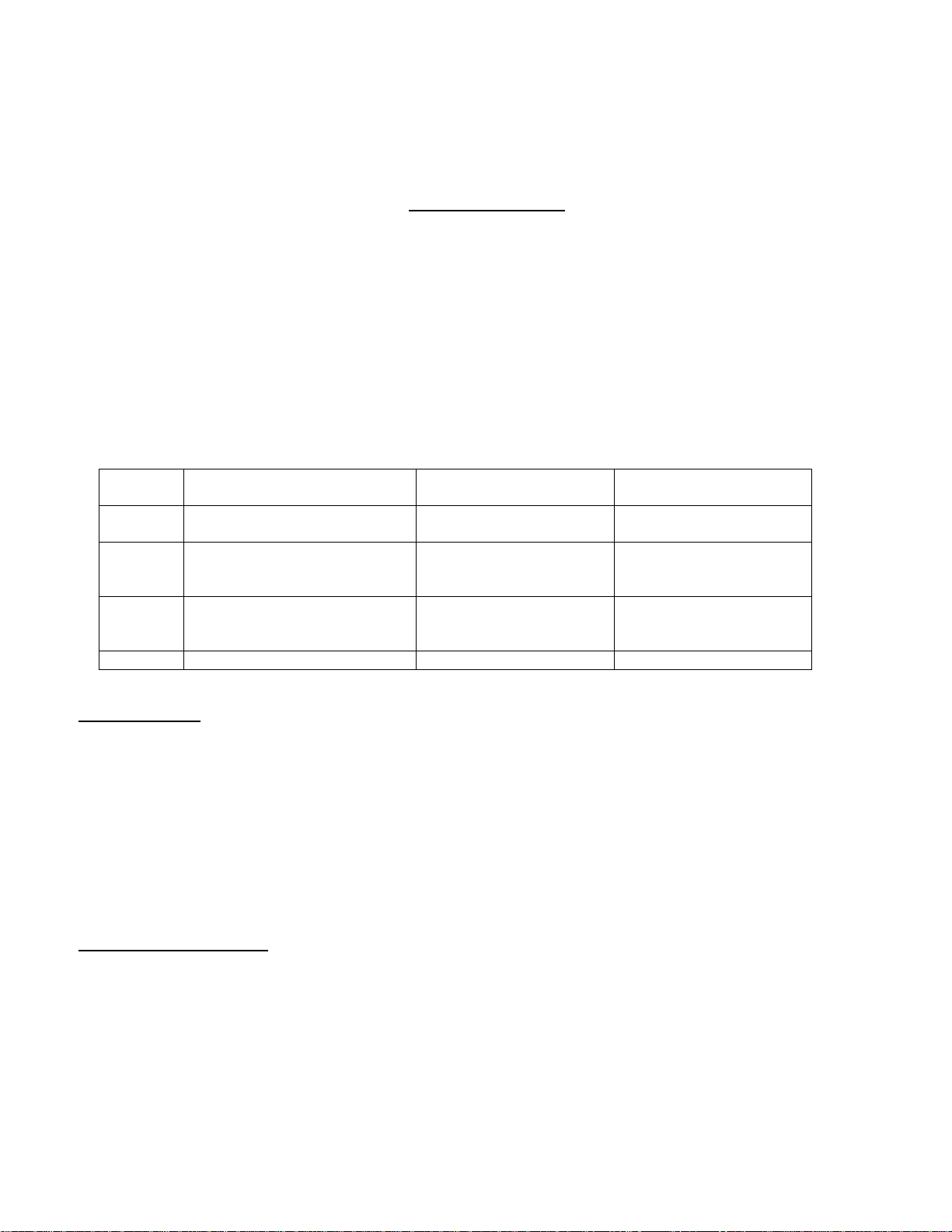
The control word options supported are:
Code Credit vs. Vend Price
Before vend is performed
Excess Cred it
(G13 Coin Acceptor)
Excess Cred it
(Coin Changegiver) #
03 Credit >= V end P rice Cancelled immedi ately Given as chang e
immediately
04 Credit >= V end P r ice Held until power removed Returned when ER
pressed or held unti l
power removed
05 Credit >= V end P r ice Held for 60 seconds Returned when ER
pressed or held for 60
seconds
06 None – Free Vend M ode Not applic able Not applicable
SOUND (On/Off)
1. Press the servi ce button repeatedly unt il
Displays So.0*
(where * is current value)
2. Press Select ion Button 1 to toggle th e setti ng Displays So.0*
3. Press Service But ton to exit
A value of 1 enables the sound, 0 disables the sound. Sounds within the menus cannot be disabled.
Negative Counter Setting
This menu option, onl y available within the SL5000 version of the s oftwar e allows the maximum capacit y to be set
for each selection. When the stock is “f illed” ( A or B b utton) these ar e the n umbers t hat are loade d into the negat ive
counters.
1.Press the Red Service button repeatedly until
Displays
nC.--
Press any selectio n : You are now in the Negative
Counter sett ing M ode
Rev. 2012.02.27
7
Page 8

p
2. Press Selection B utton 1 to increment the 0s.--. Value
(the selection number, 01 – 05, nn i s the c ur rent negat ive
counter ca
acity for this selection)
3. Press Selection B utton 2 to decrement t he 0s.--. Val ue
(the selection number, 1 – 5, nn is the current negativ e
counter capacity for this selection)
4. Press Sel ect i on Butt o n 3 to i ncr em ent the c ounter
capacity nn ( m ax im um val ue 40)
Displays 0s.nn
Displays
0s.nn
Displays 0s.nn
5. Press Selection Button 4 to decrement the counter
Displays 0s.nn
capacity nn
6. Press t he Red S er v ic e Butt on to ex i t the m ode
TEST MO DE
1. Press the servi ce button repeatedly unt il
Displays tE.- -
2. Press Service But ton to exit
In Test Mode, pressing a selection switch will operate the selected motor. If a coin is inserted its value will be
displayed f or 1 secon d.
ALL MOT O RS MODE
1. Press the servi ce button repeatedly unt il Displays AL.- -
2. Press Service But ton to exit
In this mode, press selecti on button 1 to c ommence a single test vend on all fitted motors.
CLEAR ERRORS
1. Press the servi ce button repeatedly unt il
Displays CL.- -
2. Press Service But ton to exit
In this mode, press a ny sele ction button t o clear all errors – confirmed with a “CLr” dis play.
FACTORY RE SET OF SETTINGS
1. Press the servi ce button repeatedly unt il
Displays Fr.- -
2. Press Service But ton to exit
In this mode, press selecti on button 2 for two seconds to reset to these factory default setti ngs (confirmed with a
“Set” display).
Rev. 2012.02.27
8
Page 9
Prices ; Depends on software version
A
y
Coin Valu e s: 0.05, 0.10, 0. 20, 0.5 0, 1.0 0, 2. 00
Control Word: 05
Sound: ON
Stock Mode: OFF
Payment Devices: 00 (Changegiver and Bill Reader disabled)
Negative Counters All 12
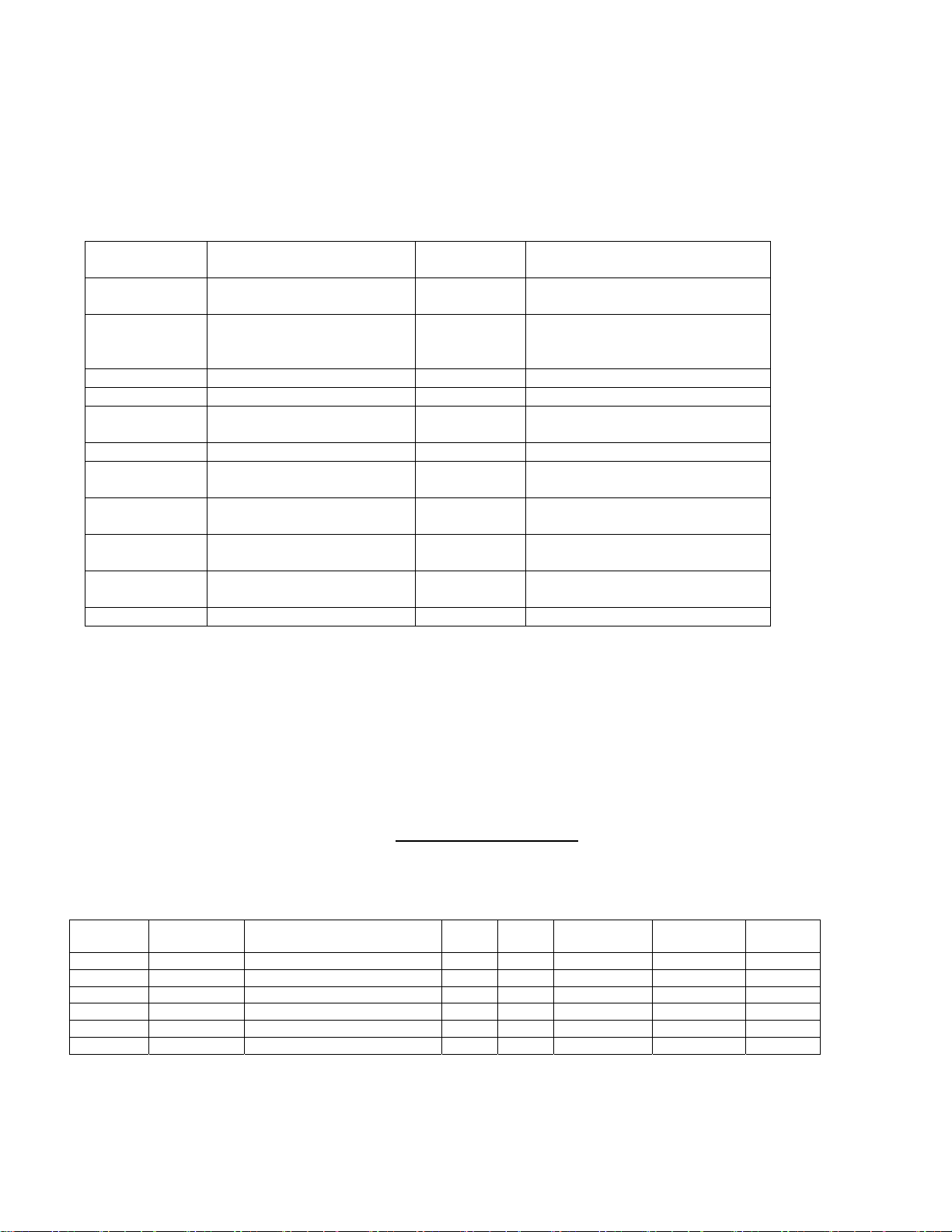
Error Codes
Error Code
Number
01 .. 16 M otor 01..16 respectiv ely
20 EEPROM Checksum Error
30 Coin Mech fault Hard Repair/r eplace Coin Mech
41 – 57 Key pad fault (key 1..16
70 Battery Low – no load
71 Battery Low – under load
72 Battery Low – batter y
73 Battery nearly low Warning Replace/recharge the battery
Soft Errors – unit will continue to operate though failed motors will show as “Sold O ut” and be blocked from operation
if selected. If t he unit has detected 8 different soft faults it will become a Hard fault.
Hard Errors – the unit is put out of service. This mode can only be cleared via the service button.
Hard* Errors – the unit is put out of service until the batter y is replaced/recharged and the servi c e butt on is pressed to
clear the error c onditions.
Fault detected Hard/Soft
respectively)
voltage too low
voltage too low
internal resi stanc e too high
fault
Soft Repair/replace motor/home
switch
Hard Factory Reset t hr ough the
menus to clear the fault, then set
up prices etc again
Hard Repair/replace keypad
Hard* Replace/recharge the battery
Hard* Replace/recharge the battery
Hard*
Replace the batter
soon
MOTOR ASSIGNMENT
The following details would be helpful in a proper assignment of the Motor version. The SL5000 uses Seaga 3 wire 12v DC gray
motor.
Motor Version Map
Version
1 Spiral Motor Seaga 3 Wire Motor 24V white Open Yes ** Individual - - - 2 Spiral Motor Seaga 3 Wire Motor 12V grey Open Yes ** Individual - - - 3 Reserved
4 Reserved
5 Reserved
6 Reserved
Name Description Start
Sense
Home Time-out Assignment Indicator
Operation
How to Set up your Motor Version:
Rev. 2012.02.27
9
ction
Page 10

To Change .. do the following:
1. Press the Red Service Button till AS Displays AS-*
wher e * is t he cur rent version #
2. Press Butto n 1 (or 2 ) to incremen t/decrement V ersion # Displ ays AS . 0? where ? is v ersion 1 to 6
3. Press Button 3 to store V ersion Value Displays set
4. Press Red Service Button or Reject to scroll to exit Displays 00.00
Notes
- When setting up a Motor Version a default Timing value will be a ssigned autom atically, (see default value). Thi s may need
to be changed (see timing value setting).
- The default motor version is Version 2.
- The VMC will return to Normal Mode (00.00) 60 seconds after the last button has been pressed unless the Red Service
Button has been pressed or the reject is pressed.
Timing Value
The tim i ng value is a measure of ti me t hat allows the VMC to either i gnore any signals from th e mot or un t i l the time has expir ed, or
if the time has expired without any signals. Depending on the Version, the timing Value has different characteristics.
Generally speaking the timing value is set to the normal vend time. For example, if the vend normally takes 6 seconds to complete,
then set the timing value to 6. This allows for the VMC to ‘expect’ a home signal at the required time and to ignore any spurious
signals in the meantime. It also sets an appropriate delay after a ‘home’ should be expected, disabling power to the motor if this
home wasn’t reached. In this case the motor is inhibited, the appropriate error code is set and the money entered is returned to the
user.
The Vend cycle is Voltage and Load dependent so an approximate setting of the timing value needs to be set. The vend cycle, is
the time from motor start (when at home) to motor end (return to Home) in seconds. This translates directly to the timing value that
re-conditions the value for correct operation.
Operation
1. Press the Red Service Button to scroll to Displays AS.—
2. Press Butto n 1 (or 2 ) to incremen t/decrement Value Displays AS.** wher e ** is value 0 1 to 99
3. Press Button 4 to store Timing Value Displays set
Notes
- The current timing value is displayed whilst doing a test as Pl.**, where ** is current value
- The timing Value can be set from 00 to 99.
- For Version 1 Motors the defaul t timing value i s 7
- For Version 2 Motors the defaul t timing value i s 7
- The timing value reverts back to default every time a version change is set
- The timing value cannot be individually assigned and applies to all outputs when set.
- The VMC will return to Normal Mode (00.00) 60 seconds after the last button has been pressed unless the Red Service
Button has been pressed or the reject is pressed.
Negative Counter Sold Out Feature
Negative Counter can only be set and calibrated for each selection by entering Service Code nc . Selection can be incremented or
decremented from 1 to 5 using buttons 1 and 2 respectively and each shelf can be allocated a negative counter from --.00 to --.99,
where - - belongs to the shelf number. Negative counter value is incremented by button 3 and decremented by button 4. Each
configuration can be saved by button no. 5.
1.Operati o n
1. Press the Red Servi c e Button Repet itively till LCD Displays:- nC .- -
You ar e now in Negative Counter Setting Mode.
2.Press Selection Button 1 to increment the **.- - Value i.e shelf sel ec tion no (** no. of shelf).
The LCD will now display the incremented selection no.
Rev. 2012.02.27
10
Page 11
3.Press Selection Button 2 to decrement the **.- - Value i.e shelf sel ec tion no (** no. of shelf).
The LCD will now display the decrement ed shelf s election no.
The Shelf for which t he Negative Counter has to be set has now been decided ; We now need to set the value of the
Negative Counter for the selected shelf.
4. Press Selection B utt on 3 to increment the - - .** Value i.e negativ e counter v alue ( ** negative counter setting).
5. Press Selection B utt on 4 to decrement the - - .** Value i.e negative counter value (** negative counter setti ng) .
Press button 5 to st or e the decided negative counter value assigned to the selected shelf.
The Display will show C.set
6. Repeat steps 2 to 5 till all t he shelves have been assigned the desired negative counter value.
7.Press Reject Button to exit
Note: Default values of all Negative Counters are factory set as per the No. of spac es in each coil. If the user changes
a coil to one which has different number of spaces then the Negative Counter pertaining to that coil will have to be
reprogrammed as per pr oc edur e m entioned earlier.
2. Negative Counter Di spl ay : T o see the c ur r ent stat us of all the Negative Counters assigned to different shelves ,
enter the service Audit mode. ( Au- - ).
In the Audit mode Press button 5 , the Negative Counter value along with the selection no ( **.- - where **
represents the shelf t hat has been select ed and the - - r epresents the curr ent v alue of t he Negative Count er that
has been assigned to that shelf.) is displayed in scrolling mode from shelf 1 to 5.
3. Sold out Feature: After setting the Negative Counter for each selection, the Negative Counter will get
decremented by 1 each time that a valid vend is made. Negative Counters for each shelf thus keep on
decrementi ng as and when a vend is made, from the set value to zero.
When t he value of any Negative Counter reaches zero, pressing the selection butt on assigned to that Ne gative
Counter will then prompt the di splay to sho w SOLD OUT. No vend can then be m ade fr om that shelf . Vends f rom
other shelves will not be interrupted and can be made as normal
Note: If a coil has 7 spaces/products, it will show SOLD OUT after vending 7 product s .
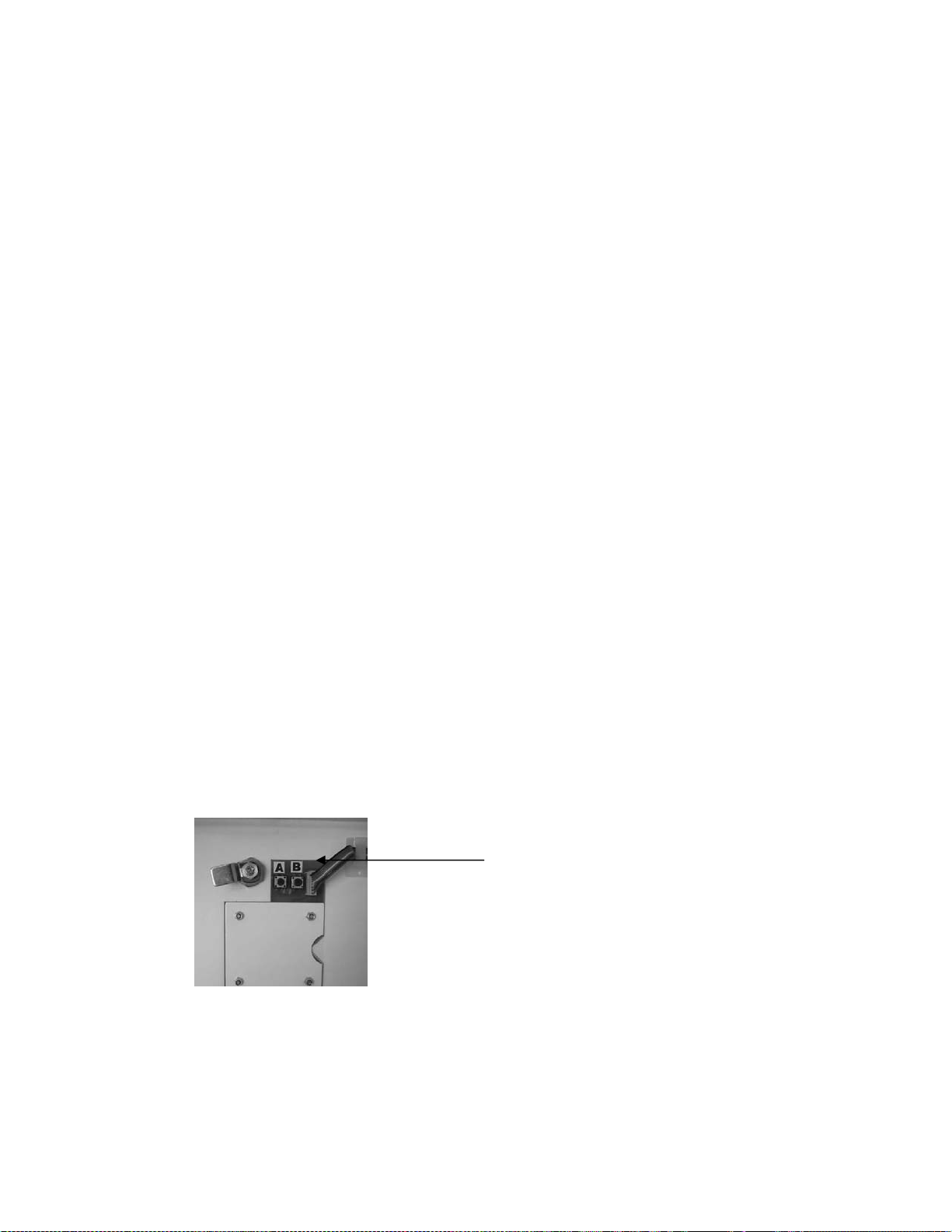
4. Resetting of Negativ e Count ers of fully vended shelv es: Button no. B (fig.2) has been assigned f or the resett i ng
of the Negative Counter of fully vended shelves. If one or more selection(s) is /are sold out, t hen k eeping the button
B pressed for 3-4 seconds will reset all the Negative Counters of the shelves which were fully sold out at that
momen t .
Button A & B
A long beep with r-ld will appear on the display indicating that partial resetting has taken place and that the
Negative Counter s which were zero pr ior to resetting have been r est or ed to set value.
The Negative Count ers of all ot her selec tions which were not fully sold out at t hat moment wil l not be di sturbed and
will maintain the value they had reached.
Rev. 2012.02.27
Fig.2
11
Page 12
Note:
a). Safety Featu re : Button B will only be operational from the moment that any of the Negative Counters have
reached to zero value.
If none of the neg. counters are zero, then pressing button no. B will not yield any results.
b). To prev ent accidental partial r es ett ing, button no. B needs to be kept pres s ed for 3-4 seconds, till t he dis play s hows
r-ld, conf irming the partial resett ing has been ex ec uted.
5. All Reset F eature: If it is desired t o totally r eset all the shelves, i rrespective of whether any of them have reached
zero value, then button no. A needs to be kept pressed for 3-4 seconds.
A long beep with ALL r-ld, on display will confirm that the resetting/reloading of all the 5 Negative Counters to their
preset val ue has tak en plac e
Note :
a) To avoid acc idental reload ing of all the neg. c ounters, but ton no. A ( fig.2) needs to be pressed f or 3-4 seconds, t ill
the display shows ALL r-ld, thereby confirming the reloading of all Negat iv e Counters.
b) It is desir able to indicat e on an Inst ruction label on the front of the machine that the cust omer should first pr ess the
selection button on the machine to check product availabilit y before inserting money int o the coin validator.
If money is fi rst inserted int o the validator and all the shelf sel ections are empt y i.e. ‘Sold O ut’ and then a selection is
made, then the displ ay will show ‘Sold O ut’ and the money will not be returned.
Test Sequence
The VMC constantly tests the operation of the machine, the data stored and the peripherals attached. Every .01
seconds, a self -test analysis is done to v erify correct operation of the machine. Further test s are done on Power Up,
Button Press, Coi n Insertion and entering/ exiting Service mode. These tests will generate t he relevant fault code as
necessary. However, it is possible t o do a thorough analysis through Servi c e Code A P , which will individually test eac h
motor as well as escrows and other related functions. Thi s i s usef ul to re-align any jammed motors.
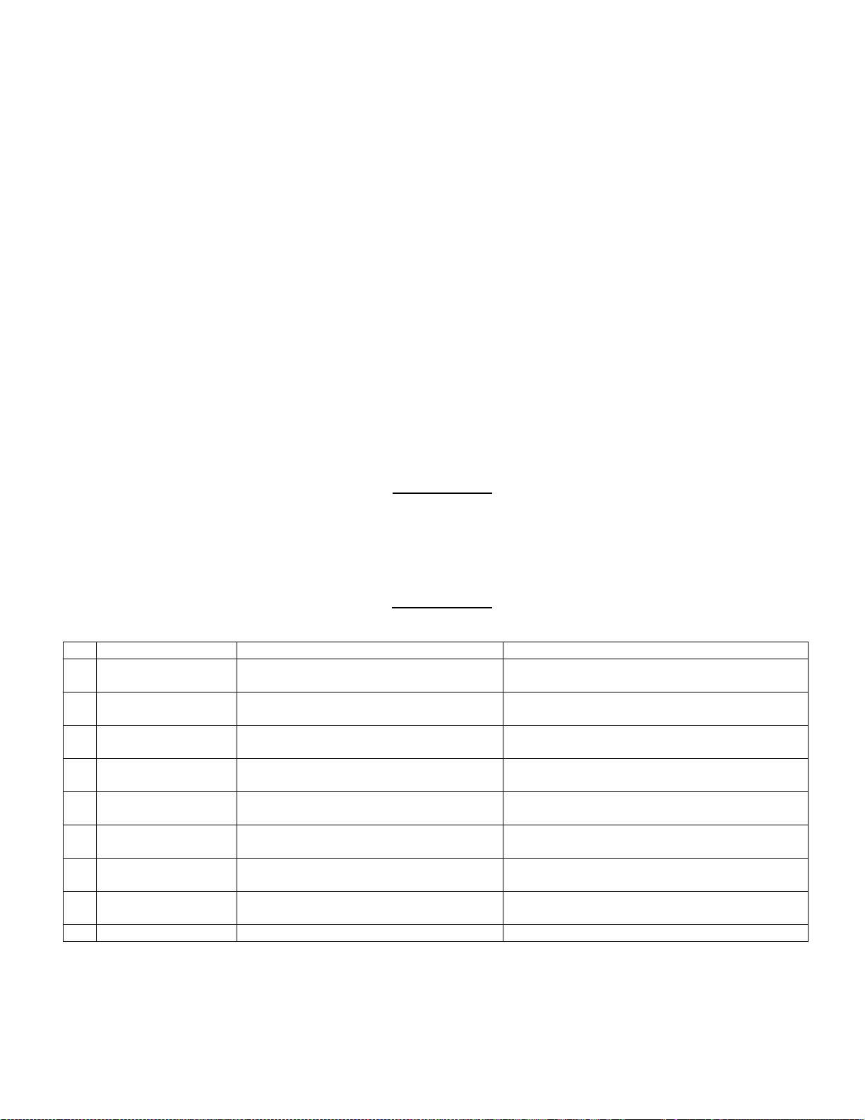
Test Code Map
TEST WHAT IS VISIBLE ACTION
1 2 Escrow Return
Power
3 4 LEDS
Price Setting
Displays ’ TEST’
Escrow Return Opens [if pr esent]
Power Status Checked
Displays ‘ 88.88 ‘ all Column LEDS on Ensure all LED Segments Ill umi nate
Confirm Prices are set
5 6 Escrow Keep Displays PL.** [ Timing Value] Escrow Keep Opens [if present]
Confirms Coi n Val ues
7 8 Motor 1
Control word
9
Motor 2
10
Motor Assignm ent
11
Motor 3
12
Coin count value
13
Motor 4
14
Audit
15
Motor 5
16
Timing belt
Displays 01.-* where * is motor Version Motor 1 operates [if present]
Confirms that a valid control word is set
Displays 02.-* where * is motor Version Motor 2 operates [if present]
Confirms that a valid motor assignment is set
Displays 03.-* where * is motor Version Motor 3 operates
Confirm that a valid coin count value is set
Displays 04.-* where * is motor Version Motor 4 operates [if present]
Confirms that all audit registers are valid
Displays 05.-* where * is motor Version Motor 5 operates [if present]
Confirms that valid timing belt value is set
17 End of Test Displays 0-.** Where ** is a fault found duri ng test
1. Press the Red Servi c e Button t o Enter S ervice Mode to scroll to Displays AP.–
You ar e now in applic ations Mode
2. Press Selection 1 to activate test sequence Displ ay s test
T he m ac hine will now perform a test as outlined below any faults that occurred will be indicated
Rev. 2012.02.27
12
Page 13
by a 2 digit code at the end of the Test Sequence. Displays Er.**
where ** may be a 2 digit code
3. Press Red Service B utt on to exit or Press Reject Button to exit.
Notes: - The test sequence may activ ate a motor for two cycles; this is nor m al.
- If aft er a test a fault code appears, correc t t he fault and test again.
- T he Dis play w ill r eturn Normal Mode 60 seconds after the last butt on has been pressed unless
the Red Service has been pressed or the rejec t is pr essed.
FACTORY DEFAULT SETTING
The SL5000 can be reverted back to factory defaults by the user by entering service code AP.-- Care m ust be taken
while doing this as all data will be lost and will have to be entered again.
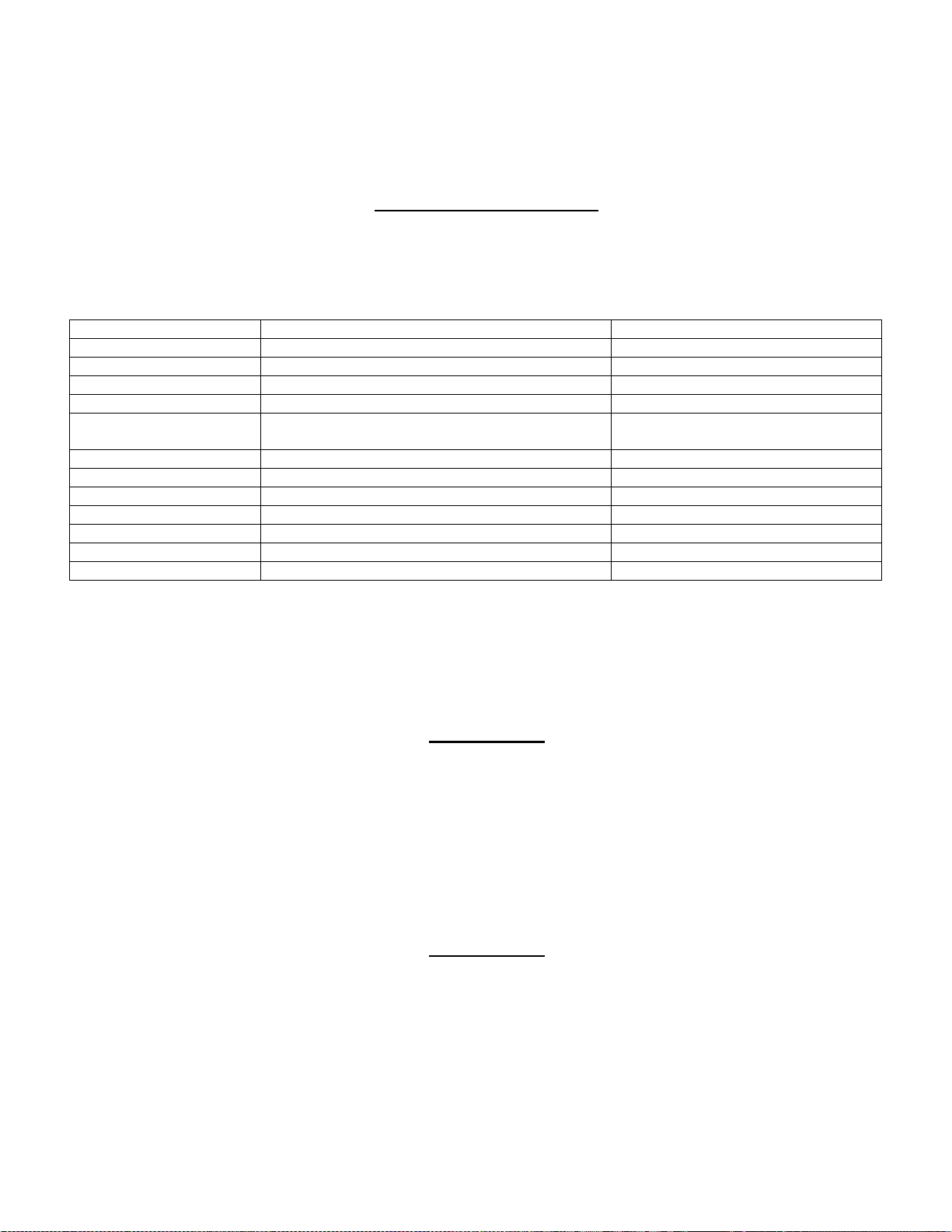
A list of factory defaults is as follows:
DATA DEFAULT VALUE TO CHANGE
Standard Audit Totals 0000.00
Prices Factory set Service Code PS
Coin Value Setti ngs Fac tory set Servic e Code Cn
Coin Count Value 15 [if escrow present]
99 [if no escrow present]
Credit [Display] 00.00
Control Word 5 [excess credit carried forward for 60 seconds] Service Code Ct
Motor Version Version 2 [all motor s] Service Code AS
Motor Timing Val ue 7 Service Code AS
Motor Assignm ent Selection 1 – Motor 1 etc Service Code AS
Motor Backup No-I ndividual Assignment ( 1) S ervice Code AS
Negative Counter Factory set
1. Press the Red Servi c e Button t o enter Application Mode Display s Ap.-
You are now in application mode
2. Press and hold selection 2 for seconds till Displays set
The machine will automatically exit from service mode and display ‘ Out Of Ord(e)r ‘
3. Press Red Service Button to re-enter Service Mode and re-confi gur e settings.
Service Code Cn
Fault Analysis
Within the mac hine there is an internal fault analysis. Every 0. 1 second the machine will do a self analysis test. This
test does not aff ect the normal operation of the machine. There will be no change of status of the machine from a
users point of view. The machine will still accept coins, di splay prices and vend pr oduc ts even during self - analysis test.
If the machi ne observes a probl em it will double verify the cause and store the er ror, which will be displayed duri ng
service m ode. To display an error c ode, simply ent er servic e mode by pressing the red but ton. T he error code will be
displayed i ntermittently. To clear an err or code, simply exit service mode (rectify error if necessary).
Note: If m ore than 5 normal er ror codes have been detect ed the machine will assume ‘Fatal err or’ status putti ng the
machine ‘Out of Or d( e) r ’.
Fault Code Map
Code Description Remedy
-- No error present None
00 Empty Error Loc ation None
01 Motor 1 Error Remove Jam-Activate Test Sequence-Exit S ervice Mode
02 Motor 2 Error Remove Jam-Activate Test Sequence-Exit S ervice Mode
03 Motor 3 Error Remove Jam-Activate Test Sequence-Exit S ervice Mode
04 Motor 4 Error Remove Jam-Activate Test Sequence-Exit S ervice Mode
05 Motor 5 Error Remove Jam-Activate Test Sequence-Exit S ervice Mode
30 Zero Price Setti ng Reset all prices - Exit Service Mode
31 Zero Coin Count Value Reset Coi n Count Value - Exit Service Mode
Rev. 2012.02.27
13
Page 14

32 Zero Control W ord Reset Contr ol Word Value - Exit Servic e Mode
33* Zero Coin Value Reset Coin V alue - Exit Service Mode
35 Incorrect Motor Version Motor Version outside of norm. Confirm Motor Version
40 Data Corrupt Pri c e Reset all Prices [Fatal error] - Exit Service Mode
41 Data Corrupt Coin Reset Coin Values [Fatal error] - Exit Serv ice Mode
42 Data Corrupt Cont r ol Reset Control Code [Fatal error] - Exit Servic e Mode
43 Data Corrupt Selec tion Reset Motor sel ec tion [Fatal error] - Exit S ervice Mode
44 Fatal Power Up Confirm Pric es, P r oduc t codes and Coi n values - Exit Service Mode
45 Power Interrupt Possible Fraud attempt - Exit Service Mode
46 Invalid Coin Output Code Replace/Reprogr am Coin Acceptor
47* Button Panel fault Check all buttons are operating cur r ently - Exit Service Mode
48 Coin Validator Error/Fault Check operat ion of Coin acceptor - Exit Service M ode
49* Coin Validat or alarm Possible fraud on Coin acceptor – Check operation of Coin Acc eptor
51* Battery Low Replace B attery - Exit Service Mode – Press any selecti on button 5 times
52 Coin Accept or Rate Low Check Coin Acceptor- Chec k battery - Exit Service Mode
53* Battery Dead Replace Batt ery - Exit Serv ice Mode - Press any selection button 5 tim es
55* Printer Communic ation Error Check P r inter operation – Disconnect printer
56* Change giver Comm’s Err or Check Change giver operation
57* Modem Communic ation Error Chec k M odem Operation
58* Note/Bill r eader Comm’s Error Check Note/Bi ll r eader oper ation
59* Cash-Less devi c e Comm’s error Check Cash-Less devic e operat ion
60* External Alarm Activation Alarm has been activated – check for machine tam pering
61* Escrow Keep Tim e-out Check Escrow Unit- Activate Test Sequence – Exit Service Mode
62* Escrow Return Time- out Check Escrow unit- A c tivate Test Sequence – Exit Service Mode
70* EEPROM Write Error Check Prices and Coin data
71* EEPROM Read Error Check Prices and Coin data
99* Machine Lock- up Code Required-Consult M ac hine S upplier
Note: * Reserved Codes – Not pr esent in current SL5000 model
SOFTWARE VERSION
Currently the VM C is powered by a Flash Based Mi c r o-Contr oller Integrated Circuit. Flash based technology i s the
latest of its ki nd and is uni que in that all data is retained within the IC even on power loss. Flash based systems also
have the advantage of being able to be re-programmed with relevant updat es.
The software versi on is displayed for a fraction of a second on exiting from service mode.
SOFTWARE RESET
As with all micropr oc essor based devices, a device reset m ust be inc orporated in case the devic e goes into loop state.
The VMC has incorpor ated on board an internal device reset or watchdog whi c h pulls the device out of any loop state.
A loop state occurs when the software locks itself on a parti c ular br anc h c ode, thus preventing the VMC from operating
correctly. Occurences of this are extremely r ar e and are usually a result of Voltage Spikes or strong Electro-Magnetic
Interferances.
The Device may also be reset by depressing the Black Reset Button on the Circuit Board. This does not affect any of
the overall oper ations of the VMC, it purely pulls the devic e bac k as if it were i nitially powered up. The only inform ation
lost on pressing the Black Button is the following: -
1.A ny Cr edit on the display will be cleared
2.A ny error Codes that occurred are cleared.
Summary Of Software Versions
Motor Version Numbers
Ver 1 2 3 4 5 6 FLASH TAS NO TES DATE
1.01 X X X Negative Counter, improved motor handling & Battery performanc e Nov ’04
**. Includes 00—07. minor device c hanges
TAS Token Access System
ACC: Accumulat ed Audit Readings
Rev. 2012.02.27
14
Page 15
Section 3 MONEY MECHANISM
COIN VALIDATOR
The Coin Vali dator receives the c oin f rom c ustomers. T he Coi n Vali dator will acc ept quart ers, dim es, and nic kel s. The
Coin Validat or can be set to accept the new golden dollar
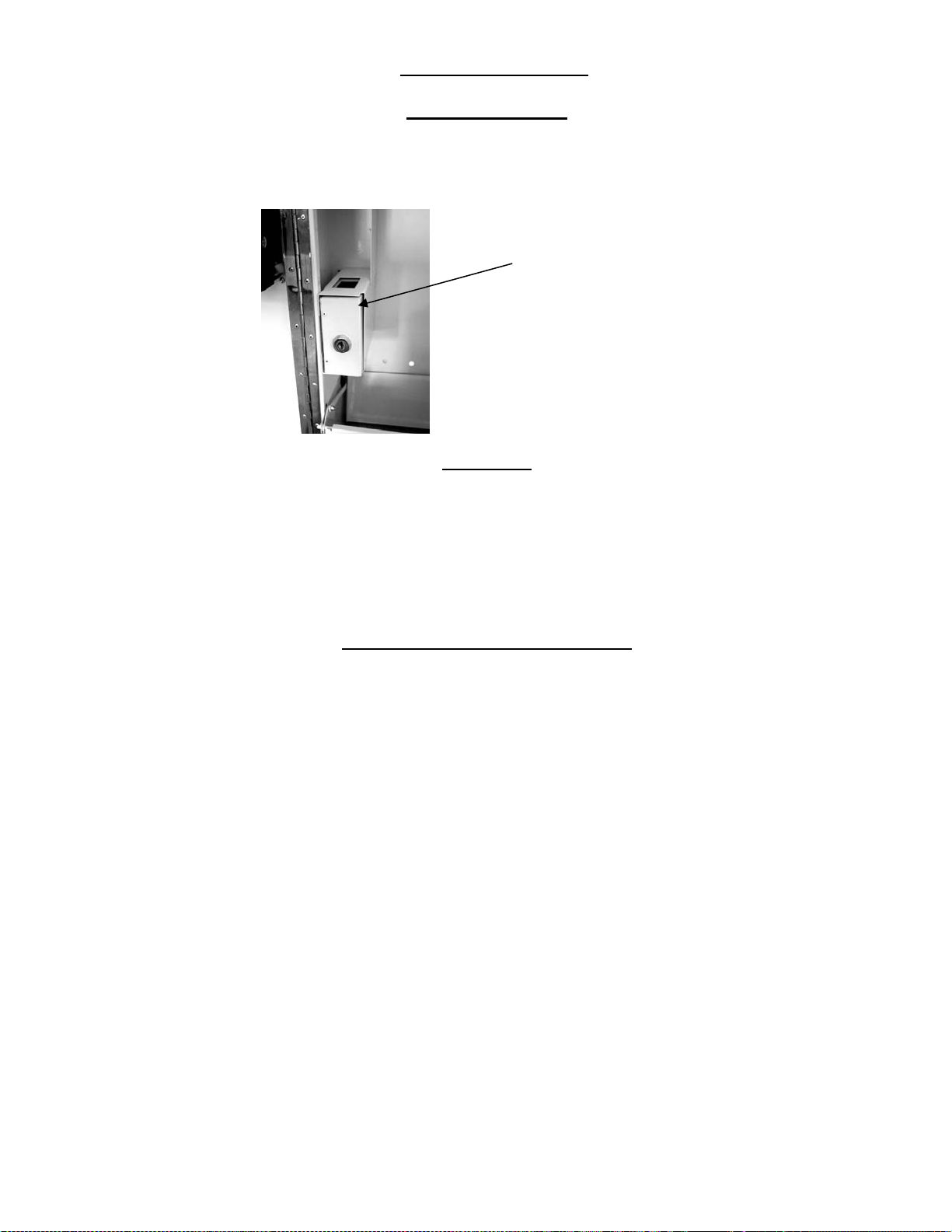
One (1) coi n box is provided with your SL5000, it is stored in the bottom left si de inside the mac hine (Fig. 3). Once the
front door is opened, pull out the coin box to empty it.
Fig. 3
Coin Box
CLEANING
Your Coin Validator needs to be cleaned only when the Coin Validator no longer reads the coin values.
1.Cleaning the Optics. You will need cotton swabs [Q-tips], and a 50/50 water/isopropyl [rubbing] alcohol solution.
a. Unlock and open the front door
b. Remove the Coi n Box, and Pull the Vertical shelf out.
c. Swab the lenses with the solution, and reassemble.
COMMON QUESTIONS AND ANSWERS
Q. How High Can I set my Prices?
A. Each selection can be priced individually up to $99. 99
Q. Can Customers reach down and help t hemselves to product?
A. No, They Can’t. The product door is a Triangle shaped fl ap desi gned to deter reach and theft. When
pushed, the back of the triangle flap will c om e in c ontact with the bottom product tray and will
become an anti-theft wall to act as a block.
Q. In the event of a power outage, will I have to reprogram my Vendor?
A. No, Your selecti on pri c es are safely stored.
Q. Coin Validator is not ac c epting Coins
A. Lenses may be dirty
Coins may be damaged or worn out
Wire harness may not be connected properly
Coin Validator may not have power
Special Note:
vends. Test vends can be performed easily by enteri ng Servic e M ode and r unning “Individual motors testing”.
We suggest that you always partially fill the vendor wit h product and perform at least five (5) t est
Rev. 2012.02.27
15
Page 16

LIMITED WARRANTY
Seaga warrants to the original purchaser that the equipment is free from defects in material and factory workmanship for a period of
one (1) year from date of shipment.
Repair or replacement of proven defective parts is limited to manufacturing defects demonstrated under normal use and service
during warranty period. Prior to returning any parts with transportation charges prepaid for replacement, the customer is to contact
Seaga’s Customer Care Department at 815.297.9500 and be assigned an RA number. Seaga will refuse any collect shipment. To
obtain an RA number, contact Seaga with complete information including the serial number(s), date of purchase and description of
the part and/or suspected defect to:
Seaga Manufacturing, Inc.
700 Seaga Drive
Freeport IL 61032
We may also be contacted, with complete information, as follows:
phone: 815.297.9500
fax: 815.297.1700
email: c ustomercare@s eagamfg.com
Seaga will repair or replace, at our option, any covered part which meets the provisions herein during the warranty period. It is our
discretion to replace defective parts with remanufactured parts. Seaga reserves the right to make changes or improvements in its
products without notice and without obligation, and without being required to make corresponding changes or improvements in
equipment already manufactured or sold.
This warranty applies only if the equipment has been serviced and maintained in strict accordance with the instructions presented i n
the Operator’s Manual and no unauthorized service, repair, alteration or disassembly has been performed. Any defects caused by
improper power source, poor water quality or pressure , an installed wate r filtration system not fully functioning, abuse of the product,
accident, alteration, vandalism, improper service and maintenance schedules, neglecting to de-scale and sanitize on a regular
basis, use of products or ingredients not allowed in the machine, corrosion due to use of non-approved detergents or cleaning
solutions, or damage incurred during return shipment will not be covered by this warranty. Further, equipment that has had the
serial number removed, altered or otherwise defaced will not be covered by this warranty.
Lighting components, refrigerant, glass, paint, decals, fuses, filters or hygiene replacement parts, labor and/or installation are not
covered by this warranty.
Follow proper maintenance procedures and use of equipment, as described in the Operator’s Manual provided on Seaga’s web site
at seagamfg.com, which include but are not limited to:
Cleaning of equipment including regular maintenance
Proper installation and location of equipmen t with respe ct for the indicated te mpe rature and humidity leve ls
Proper use of equipment including loading, programming and setup
THIS WARRANTY IS IN LIEU OF ALL OTHER WARRANTIES, EXPRESSED OR IMPLIED, TO INCLUDE, BUT
NOT LIMITED TO, WARRANTIES OF MERCHANT ABIL IT Y AND FIT NESS FO R A PARTICUL AR PURPOSE AS TO
THE UNIT AND ACCESSORIES. UNDER NO CIRCUMSTANCES SHALL SEAGA BEAR RESPONSIBILITY FOR
ANY INCIDENTAL, CONSEQUENTIAL, PUNITIVE OR SPECIAL LOSSES OR EXPENSES. Seaga neither
assumes nor au thorizes any person to assu me for it any obligati on or liability in connect ion with the sale o f
said unit(s) or any part(s) thereof.
SMI2455562
Rev. 2012.02.27
16
 Loading...