

Page 1
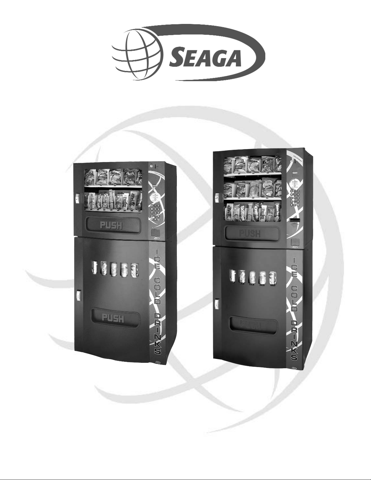
Operator’s Manual
Seaga Manufacturing, Inc.
700 Seaga Drive
Freeport, IL USA 61032
www.seagamfg.com
HF2000 HF3000
HF2500 HF3500
Page 2
The Elite Automatic Series Vendor
INTRODUCTION
This manual is divided into three (3) main sections, Elite Snack Vendor, Money Mechanisms, and Elite Beverage Vendor. This
manual focuses on the HF3500 as it is the largest of the series, there will be points that apply only to the HF3500, and those
items will be identified for clarity.
IMPORT
ANT NOTICES
Your vendor(s) are intended for indoor use only.
Your vendor(s) must be set on a level, well -supported location.
Leave at least 10" between the left- hand side of the vendor and wall.
Leave at least 10" between the back of the vendor and wall.
Condenser cooling air is taken in the left and exhausted out the back.
Always unload vendor before transporting it.
Do not load your vendor with disfigured or damaged product.
Temperature is factory set. Allow your vendor(s) to operate for twenty-four (24) hours before attempting any adjustments.
Section 1
ELITE SNACK VENDOR
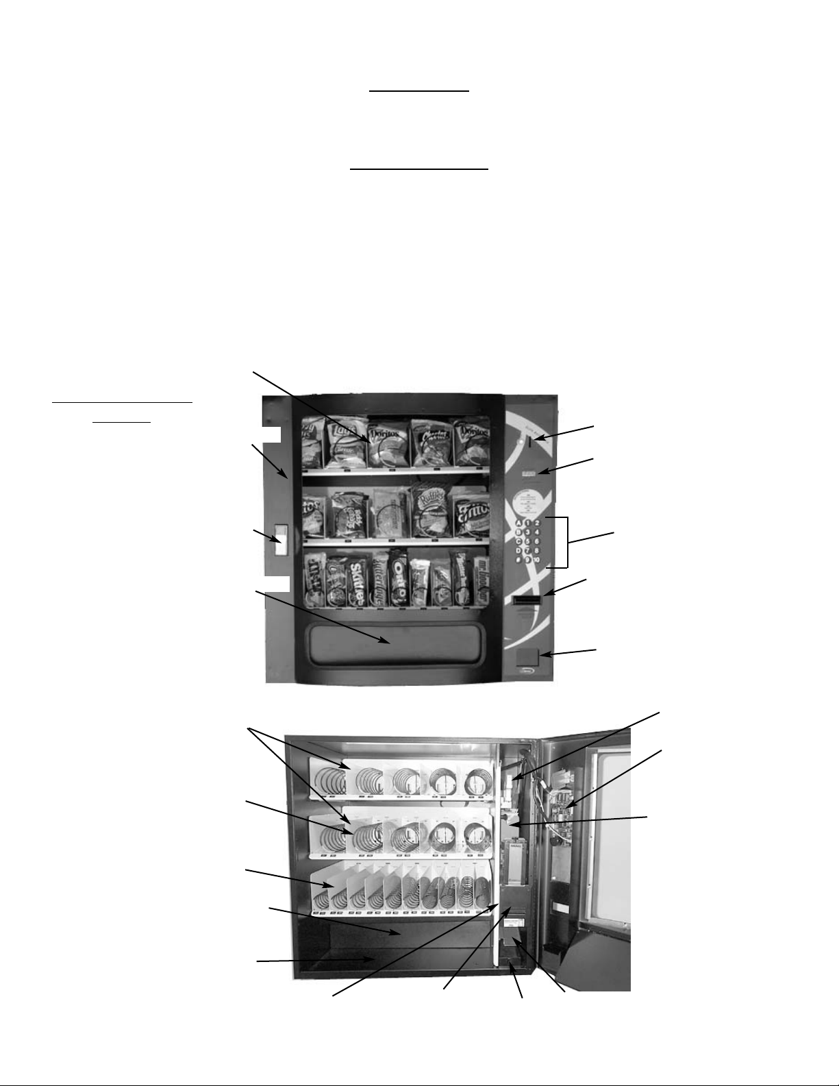
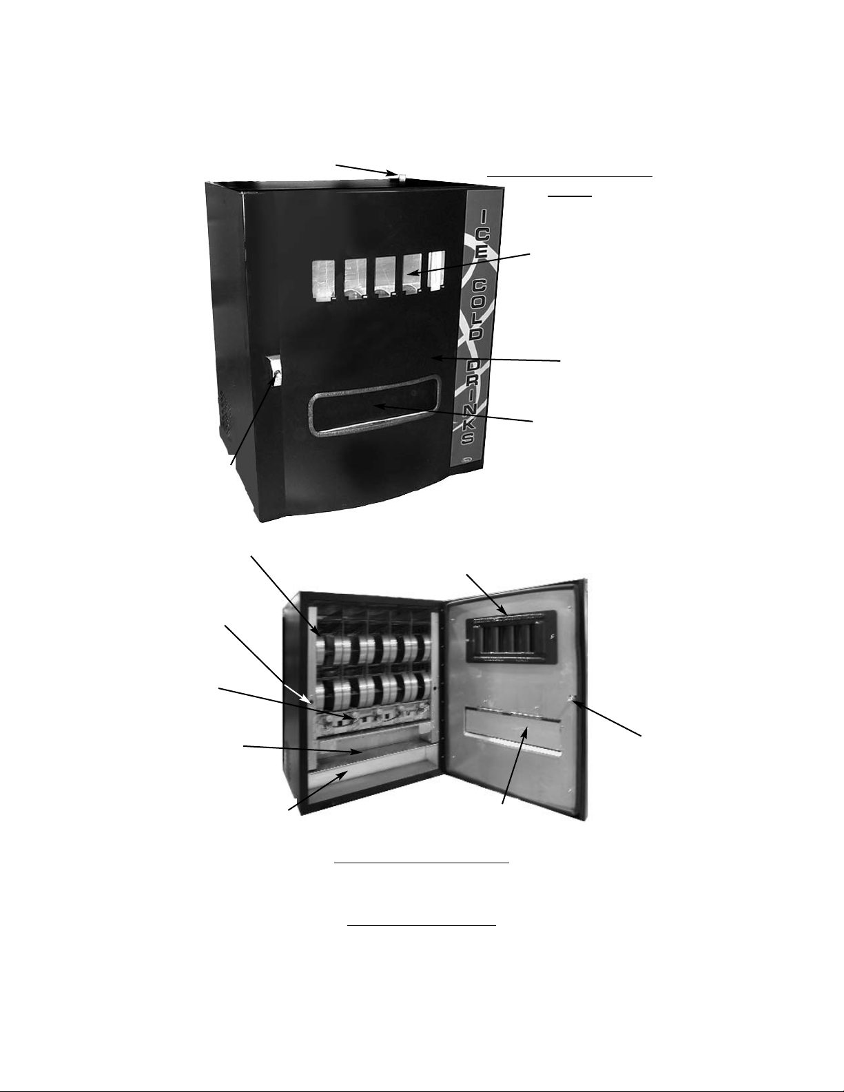
Elite Snack Vendor
HF3000
(HF2000 Not Shown)
Coin Slot and
Return Button
LED Display
Display
Window
Keypad
Front Door
Lock
Product Door
Optional
(HF3000 only)
Bill Validator
Coin Return
Door
Note: HF2000 has only
two (2) Product Trays
(Interior view with Front Door open)
Product Tray
(5 Select)
HF3000 2
HF2000 1
Product Tray
(10 Select)
Circuit Board
Bill Validator
(optional
HF3000 only)
Coin Return
Chute
Coin Validator
Coin Return
Arm
Vertical Shelf
Coin
Tray
Helix Coils
HF3000 20
HF2000 15
Vend Area
Anti-Theft Wall
Page 3
LOCK
Your Elite Snack Vendor has one Lock, more commonly known as a "T" handle Lock. To unlock the Front Panel, insert key and
turn clockwise ¼ turn. When unlocked the "T" of the Lock will pop out from the vendor. Turn ¼ turn clockwise to open Front
Panel.
MOUNTING
Your Elite Snack Vendor can be mounted to either an optional Stand or to the Elite Beverage Vendor.
The optional Stand comes pre-assembled, with mounting hardware. You will need tools for mounting.
1. To Mount to optional Stand.
A. Unlock and open Stand.
B. Set vendor on top of Stand.
C. Unlock and open Front Door.
D. Remove bottom Product Tray. Pull Product Tray fully forward,
keeping it level.
E. Lift Product Tray to release from the track. Then it can be pulled
forward and lifted out.
CAUTION: The Product Tray Wire Harness will need to be unplugged prior to complete removal of the Product Tray. The Wiring
Harness is plugged into the inside right-hand side of the vendor. You may need assistance.
F. Set back of Product Tray into Vend area, steady it with one hand, and disconnect the Wiring Harness.
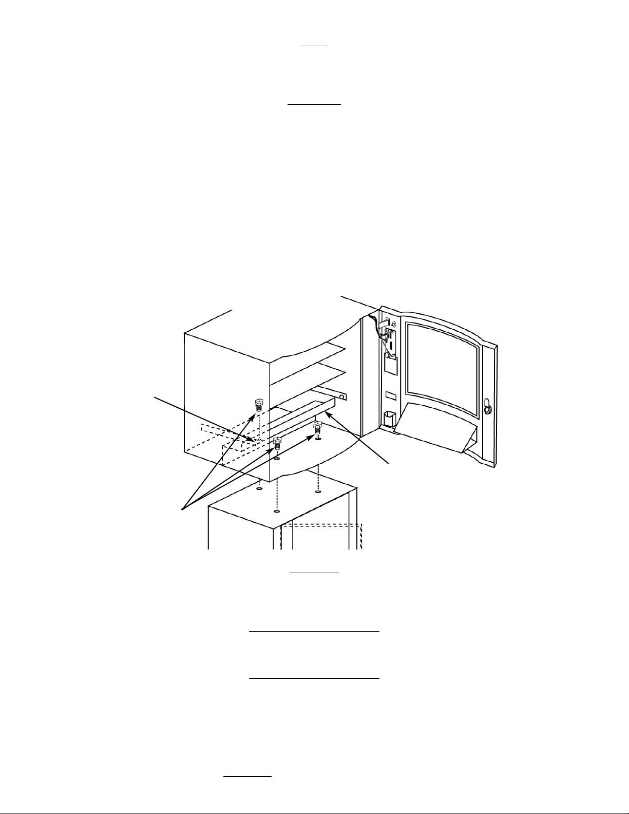
G. Attach Stand to bottom of vendor. Insert 3 bolts down through the vendor into welded nuts in the top of the Stand.
Tighten. (Fig. 1)
Mounting to the optional Elite Beverage Vendor will be explained in that section of the Manual (Pg. 20)
LEVELING
Once your vendor is in its new location, you will need to level it to insure proper operation. You will need a level. We recommend
a 3ft(1m) level, as it will give a more accurate reading than a small torpedo level. There are threaded Levelers included with your
vendor. These Levelers screw into the bottom of your Stand and can then be adjusted up or down as needed.
ELECTRICAL
CONNECTION
The Elite Snack Vendor requires one (1) 120 VAC grounded outlet for each vendor(s).
Elite Snack Vendor 120 Volts Less than 1 Amp
KEYPAD AND LED DISPLAY
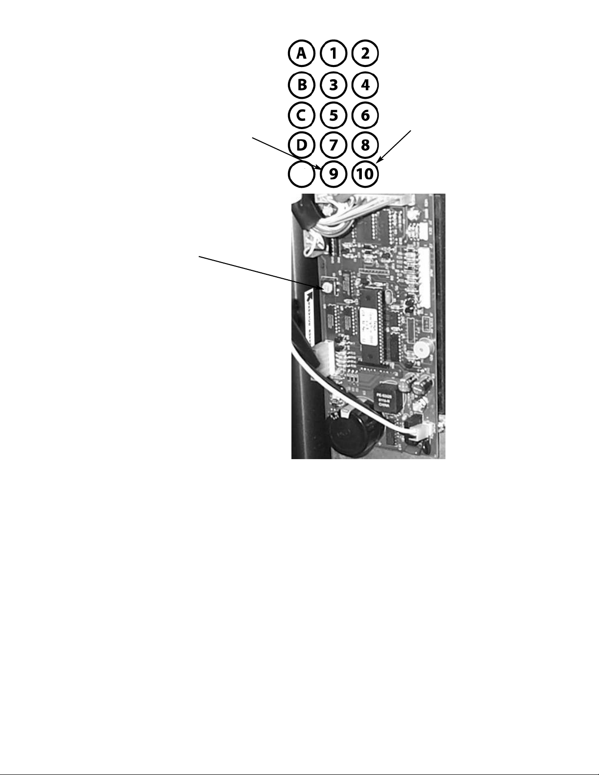
The Keypad (Fig. 2) is a touch sensitive operation. Light pressure will be necessary to activate each number or letter. The vendor's Keypad is used by the customer to make their selection, and by the operator to set and test many functions of the vendor.
The LED Display shows the customer the amount of money entered into the vendor, and the cost of their selection, it shows the
operator the Service Mode functions for setting and testing the various functions of the vendor.
1. To Access Operator Functions:
A.) Unlock and open the Front Door to access the Circuit Board, and
enter Service Mode by pressing the Red Service Mode Button. (Fig. 3)
Figure 1 Optional Stand Mount
Rear hole is
hidden
behind the
Anti-Theft
Wall
Anti-Theft
Wall
Bolts
Page 4
(The following information is repeated, for your convenience, on a sticker within the vendor.)
SERVICE MODE
The Service Mode is entered and exited by pressing the Red Service Mode button on the Circuit Board. All Service Mode functions are cycled and selected by pressing the DOWN (9) and UP (10) keys. If no action is taken within 20 seconds the display
will return to Standard Operating Mode.
MOTOR COUNT ("Cnt")-displays the total count of motors available in this vendor.
Enter Service Mode. Cycle through the Service Mode until the display reads "Cnt". Press any keypad character other
than the DOWN (9) or UP (10) key and the controller will display the motors it recognizes. The total number of motors should
equal the total number of selections.
BILL ESCROW ("ES")-optional setting that when ON will return the bill to the customer on demand, when OFF the vendor will
return coins to the customer.
Enter Service Mode. Cycle through the Service Mode until the display reads "ES". Press any keypad character other
than the DOWN (9) or UP (10) key to turn this mode ON ("ES y") or OFF ("ES n").
MULTI-VEND MODE ("UL")-optional setting that when ON allows more than one vend to be performed, provided there is still
credit remaining.
Enter Service Mode. Cycle through the Service Mode until the display reads "UL". Press any keypad character other
than the DOWN (9) or UP (10) key to turn this mode ON ("UL y") or OFF ("UL n").
FORCE-VEND MODE ("FC")-optional setting that when ON requires a purchase once credit has been deposited.
Enter Service Mode. Cycle through the Service Mode until the display reads "FC". Press any keypad character other
than the DOWN (9) or UP (10) key to turn this mode ON ("FC y") or OFF ("FC n").
Figure 2 Keypad Layout
Down (in
Service Mode)
Up (in Service
Mode)
Figure 3 Service Mode Button
Red Service Mode Button
(Circuit Board inside
Front Panel)
E
NOTE: when plugging in wire
harnesses after servicing, be
aware that the side of the wire
harness plug that shows silver
connectors always face the outside edge of the circuit board.
Page 5
BEVERAGE SOLD-OUT MODE ("Can")-optional setting that when ON operates sold-out function for this vendor, and will flash
“Make Alternate Selection”.
Enter Service Mode. Cycle through the Service Mode until the display reads "Can". Press any keypad character other
than the DOWN (9) or UP (10) key to turn this mode ON ("Can y") or OFF ("Can n").
TEST ALL MOTORS ("Test")-allows user to test all motors in your vendor.
Enter Service Mode. Cycle through the Service Mode until the display reads "Test". Press any keypad character other
than the DOWN (9) or UP (10) key to test all motors. No other function can be accessed during the test. The time this function
requires will vary.
INDIVIDUAL MOTOR TESTING ("Slct")-allows user to individually test each motor in this vendor.
Enter Service Mode. Cycle through the Service Mode until the display reads "Slct". Enter any selection to test it's motor.
(ex. A1)
PRICE SETTING ("Prc")-allows the user to set individual prices for each motor or item loaded in your vendor.
Enter Service Mode. Cycle through the Service Mode until the display reads "Prc". Enter any selection to display current price.
(ex. A1) Press the DOWN (9) or UP (10) key to change the price for that selection. Price settings will change in 5 cent increments. Press
"A" to save the new price.
CASH HISTORY ("Cash")- displays total cash count.
Enter Service Mode. Cycle through the Service Mode until the display reads "Cash". Press any keypad character other than
the DOWN (9) or UP (10) key to display the total cash count the vendor has accumulated. This function cannot be reset to zero.
SALES HISTORY ("Sale")-displays total vend count.
Enter Service Mode. Cycle through the Service Mode until the display reads "Sale". Press any keypad character other than the
DOWN (9) or UP (10) key to display the total vend count that your vendor has performed. This function cannot be reset to zero.
COIN DISPENSING ("Coin")-allows user to manually dispense coins from the Coin Mechanism by coin type.
Enter Service Mode. Cycle through the Service Mode until the display reads "Coin". Pressing keys 1-7 will dispense the lowest through the highest denomination of coins. For American Coin Mechanisms key 1 will dispense nickels, key 2 will dispense dimes,
and key 3 will dispense quarters.
Special Note: To avoid true customer aggravation, Multi-Vend and Force-Vend should NOT be turned on at the same time.
DELIVER
Y
SYSTEM
The Delivery System of your Elite Snack Vendor consists of the Keypad, LED Display, Driver Motors, Product Trays, Product Chutes,
and Helix Coils. The customer inserts money and enters their selection on the Keypad. The selection's Driver Motor turns the Helix
Coil that vends the product.
LOADING PRODUCT
To present your product in as an attractive and professional manner as possible, do not load any damaged items, and make sure items
are facing forward for easy identification by your customer.
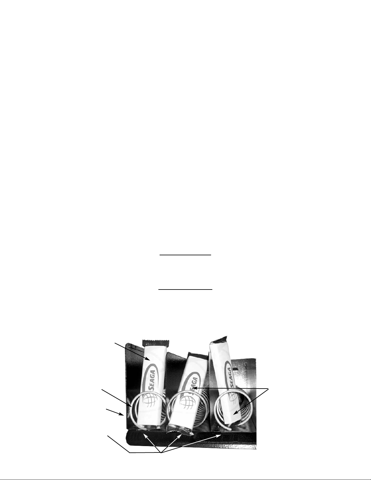
Note: The size of the item being vended must be larger than the Helix Coil, but smaller than the Column, to vend correctly. Never force
an oversized item into the Helix Coil or Column, nor attempt to vend an item that is smaller than the Helix Coil as this will create problems and deter customers. (Fig.4)
Figure 4 Loading Product
Correct - load
product between
Helix Coils,
resting on the
product tray
Incorrect
Product Tray
Columns
Helix Coil
Front view
Page 6
1. To Load Product:
A.) Pull out desired Product Tray all of the way forward. Product Tray will tilt down. Note: Pull out only one (1)
Product Tray at a time.
B.) Place product in proper size Helix Coil. Note: Bottom of product must
rest on the Product Tray and not on the Helix
Coil. (Fig. 4) Load each Column from front to back. Note: Fill all Product Trays fully, do not leave any spaces
behind or between items.
C.) Once Product Tray is fully loaded, lift and push it back in. Repeat above steps until all Product Trays are
fully loaded.
To increase the length of the Helix Coil, white plastic Product Pushers can be snapped on the end. A supply of Product
Pushers are provided in the vendors hardware bag.
Special Note: We suggest that you always partially fill the vendor with product and perform at least five (5) test vends. Test
vends can be performed easily by entering Service Mode and running "Individual Motor Testing". (See: Keypad and LED
Display, Individual Motor Testing.)
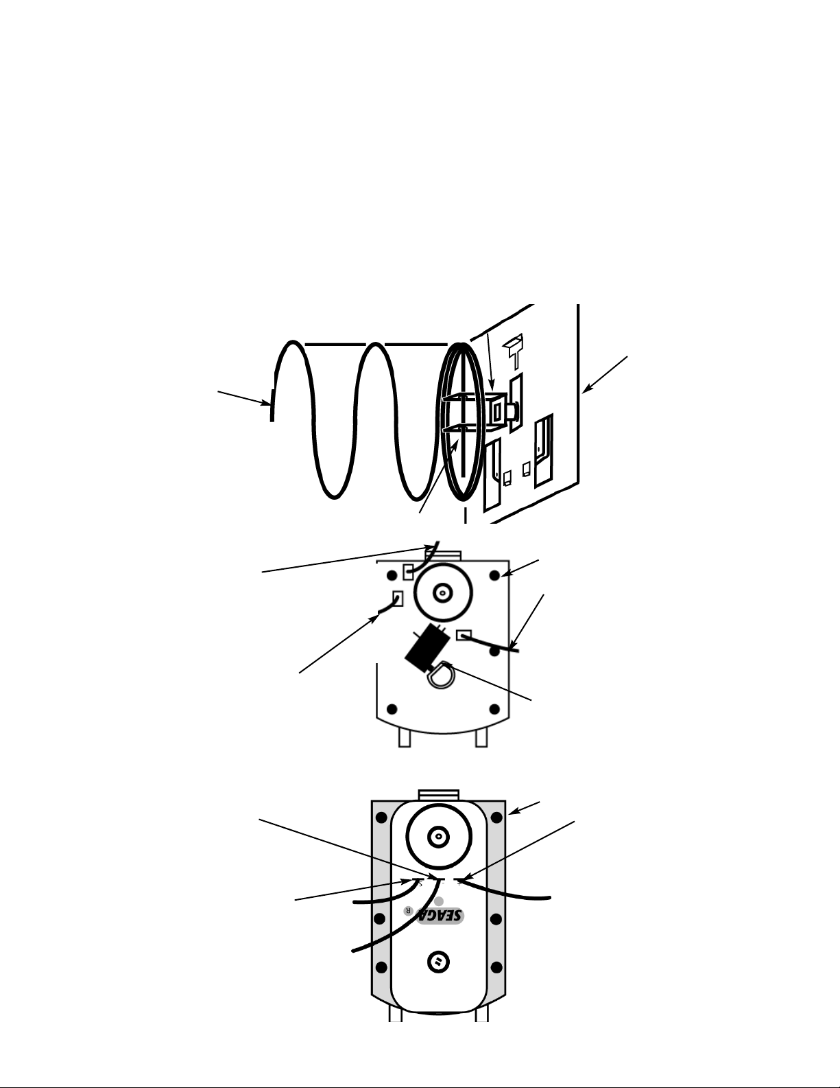
Driver Motor
(behind
Product Tray)
Helix Coil
Driver
Figure 5 Delivery System
Note: “Home” position
At “Home” switch is
not depressed
Figure 6 Gray and White Driver Motor
Driver Motor
White Wire with Gray
Stripe on 10 select
trays; Black Wire on
5 select trays
Color Wire
varies by Product Tray.
Top 5 select Red
Center 5 select Orange
Bottom 10 select Yellow.
Color Wire varies by Product
Tray and left to right.
Top Blue, Purple, Brown, Gray,
White
Center Blue, Purple, Brown, Gray,
White
Bottom Blue, Purple, Brown, Gray, White, White / Red stripe, White / Orange stripe,
White / Yellow stripe, White / Green stripe, White / Blue stripe
Driver Motor
(S) White Wire with
Gray Stripe on 10
select tray; Black
Wire on 5 select tray
Color Wire (+)
varies by Product
Tray and left to
right.
Top Blue, Purple,
Brown, Gray, White
Center Blue, Purple,
Brown, Gray, White
Bottom Blue,
Purple, Brown, Gray,
White, White / Red
stripe, White /
Orange stripe, White
/ Yellow stripe, White
/ Green stripe, White
/ Blue stripe
Color Wire (-)
Color varies by Product Tray.
Top 5 select Red
Center 5 select Orange
Bottom 10 select Yellow.
Black Driver Motor
Page 7
DRIVER MOTORS
Each selection is vended by the action of the Driver Motor. The HF3000 has 20 Driver Motors and the HF2000 has 15. The Driver
Motors are clipped to the rear of each Product Tray.
In the rare event of a jam a Driver Motor may need to be returned to its home position. The home position is when the shaft of
the Helix Coil that is held by the Driver is vertical, with the end of the shaft pointing down. (Fig. 5)
1. To "Home" a Driver Motor.
A.) Unlock and open the Front door to access the Circuit board, and enter Service Mode by pressing the
Red Service Mode Button (Fig. 3)
B.) Cycle through the Service Mode until the display reads “SLCT”.
C.) Enter the letter and number of the motor you wish to home. The motor will rotate to it’s home position.
2. To Remove a Driver Motor.
A.) Unlock and open Front Door
B.) Pull Product Tray fully forward, keeping it level.
C.) Lift Product Tray to release from the track. Then can be pulled forward and lifted out.
Caution: The Product Tray Wire Harness will need to be unplugged prior to complete removal of the product tray. The Wiring
Harness is plugged into the inside right-hand side of the vendor. You may need assistance.
D.) Set back of Product Tray into Vend area, steady it with one hand, and disconnect the Wiring Harness.
E.) Remove Helix Coil from Driver by lifting the front end of the Helix Coil up with one hand while guiding the rear of
the Helix Coil with the other. Note: This operation is more difficult with the smaller Helix Coils.
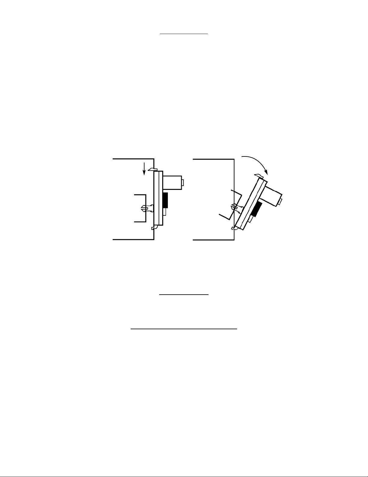
F.) Depress the top tab on the Driver Motor, tilt the Driver Motor backwards, and lift the Driver Motor free. (Fig. 7)
G.) Disconnect Wires.
H.) Replace Driver Motor by repeating above steps in reverse order.
GENERAL
NOTES
It is suggested that a toolbox accompany you to each of your locations. Suggested items for this toolbox would include a socket set, (up to a 1/2" socket size suggested) a Phillips and a Standard screwdriver. Additional items would be a soft rag and
perhaps a Black Magic marker. The magic marker is useful in touching up light scratches that may occur to your vendor.
COMMON QUESTIONS AND ANSWERS
Q: How high can I set my prices?
A: Each selection can be individually priced up to $95.95.
Q: Can customers reach up and help themselves to product?
A: No. The Product Door is a Triangle shape designed to deter reach up theft.
When pushed, the back of the door will come in contact with the
bottom Product Tray and the Anti-Theft Wall to act as a block.
Q: My vendor is plugged into a live outlet, I have tested the outlet, but my vendor has no power.
A: Unplug the vendor for 5 minutes. This will reset the thermal breaker on the transformer.
Q: Motor does not cycle.
A: Check the Wire Harness on the motor for a loose wire.
Check to see if the motor is jammed or out of home. Home the motor per
"Driver Motors".
Q: When I make a particular selection, the display reads fail.
A: Perform the "Motor Count" per "Keypad and LED Display" Pg.6. If the
Press
Tilt
Figure 7 Motor Removal
Page 8
number of Driver Motors found, matches the total number of
selections, check the wiring connections at the Driver Motor and
the Circuit Board.
Q: Motor cycles but product will not drop.
A: Check to see if the product is jammed in the Product Chute.
Check to see if the vendor is level.
Check product for damage, and make sure it is the proper size.
Install Product pushers on the ends of the Helix Coils to assist in vending.
Q: In the event of a power outage, will I have to reprogram my vendor?
A: No. Your selection prices are safely stored.
Q: The vendor will not allow me to change prices.
A: Reset the Circuit Board by pressing the Red Service Mode button while
unplugging the vendor. You may need assistance. You will need to
reenter all prices. Note: This will not reset "Cash Hist" or
“Sales Hist".
Section 2
MONEY MECHANISMS
COIN V
ALIDATOR
Note: The manufacturer's Coin Validator manual is packed with your vendor. The following is intended as an addendum to the
manufacturer's manual.
The Coin Validator receives and returns change to your customers. The Coin Validator is installed at the factory, and will accept
quarters, dimes, and nickels. The Coin Validator can be set to accept the new golden dollar. Quarters that are not needed to maintain inventory in the Quarter Tube, and all other coins are diverted to the Coin Tray.
It is recommended that you initially load the tubes at least half full when setting up your vendor and that you not allow your vendor's coin inventory to drop below that.
COIN RETRIEV
AL
Coins can be retrieved from the vendor in three (3) ways, the Coin Tray, Manual Coin Retrieval Buttons, and the Coin Return
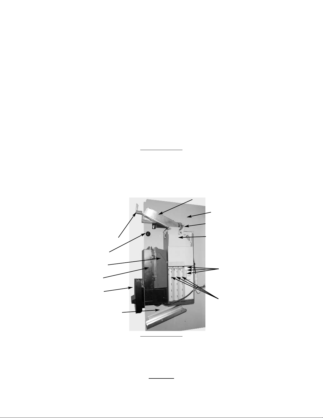
Button. The Coin Tray sits below the Vertical Shelf. The Coin Tray holds all accepted coins, except for quarters needed to maintain inventory in the Quarter Tube. (Some overflow may occur.) The Manual Coin Retrieval Buttons are along side the Dime Tube,
pressing a button will dispense one (1) of the selected coins. With the Vertical Shelf pulled out, you will want to catch the coins
as they are dispensed. The Coin Return Button moves the Coin Return Arm, and pushes the Coin Return Lever returning coins
to the customer that have been inserted.
CAP
ACITY
The Coin Validator will hold $20 in quarters, $10.60 in dimes, and $3.65 in nickels. The Coin Validator can be set to maintain
Elite Snack
Money Mechanisms
(Interior view with
Vertical Shelf extended)
Coin Return Arm
Coin Chute
Vertical Shelf
Bill Validator
Bill Stacker
Bill Storage Box
Coin Return Slide
Coin Hopper
Manual Coin
Retrieval
Buttons
(From
top, Quarters,
Nickels,
Dimes)
Coin Tubes
(From left,
Quarters,
Nickels,
Dimes)
Knob
Coin Return Lever
Page 9
either $4.50 or $20 in the Quarter Tube. If you intend to vend high-ticket (over $1) items through your vendor, or the vendor is in
a high traffic area, you may want to set the Coin Validator to maintain a full Quarter Tube. The Bill Validator will not accept $5
bills unless the quarter tube is nearly full. Refer to the manufacturer's manual to adjust option switch settings.
CLEARING JAMS
To clear a jam, remove the Hopper Assembly.
1. To Remove the Hopper Assembly.
A.) Unlock and open the Front Door, unplug vendor.
B.) Remove the Coin Tray, and pull the Vertical Shelf out.
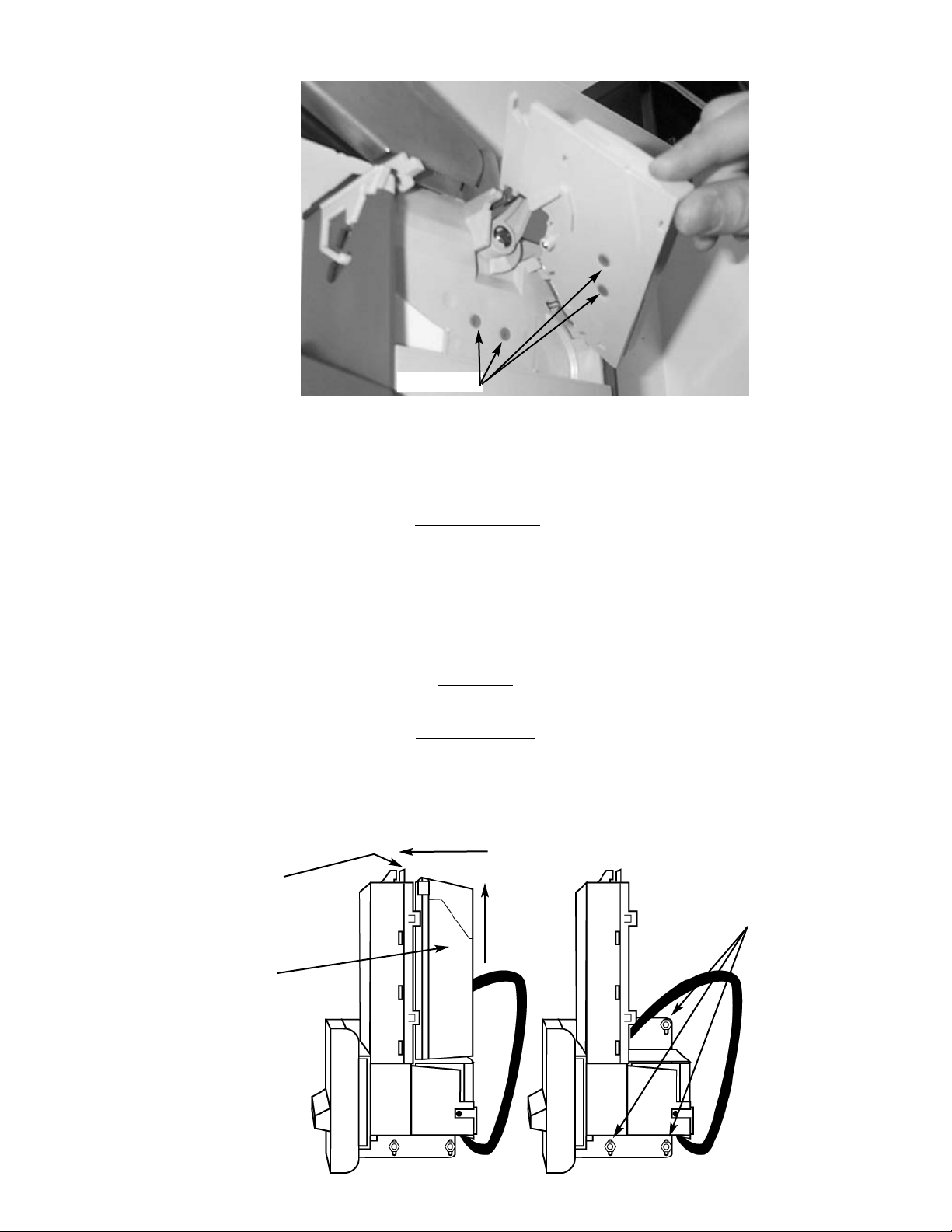
C.) Loosen the two (2) mounting screws that hold the Coin Return Arm
and Coin Chute to the Vertical Shelf, and shift this assembly up.
This assembly does not need to be removed.
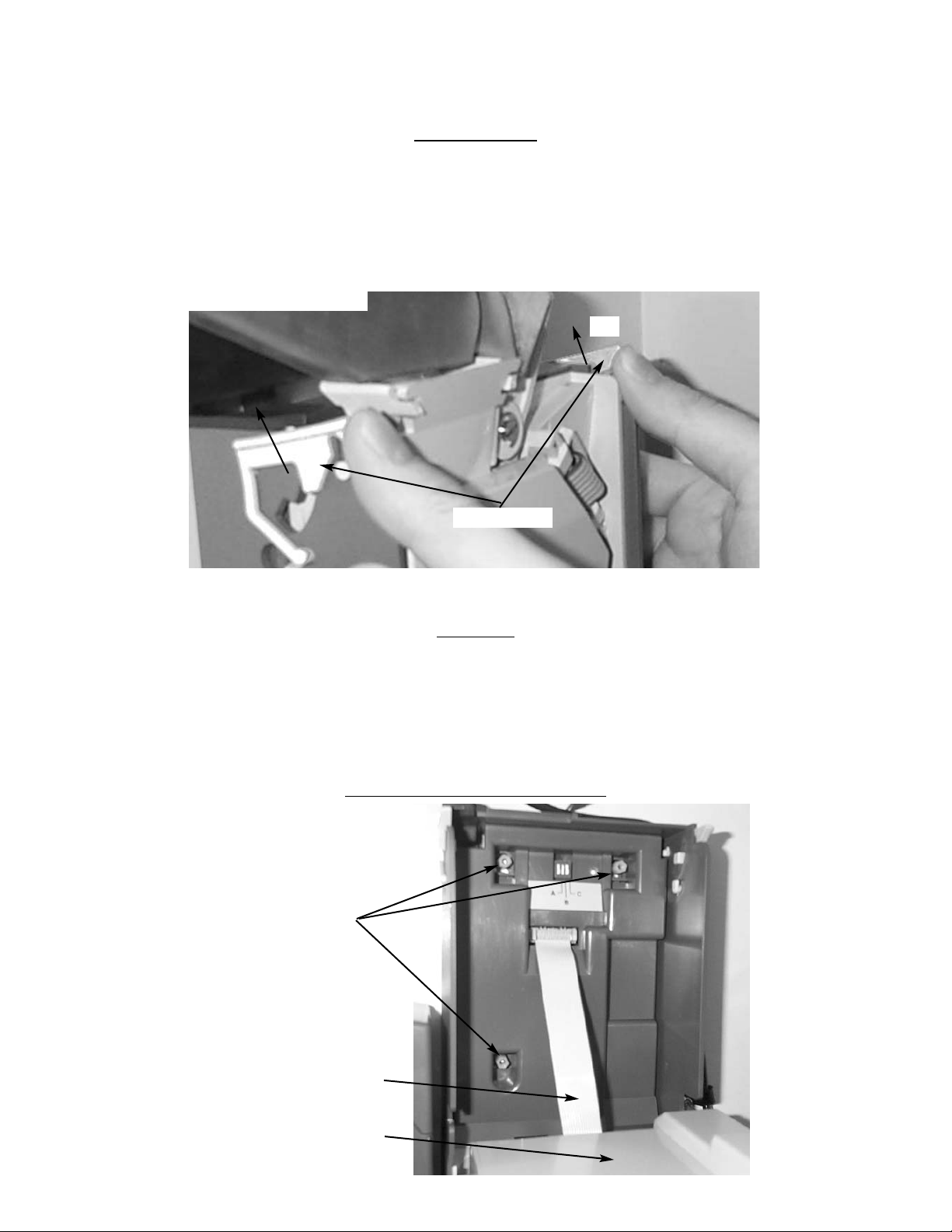
D.) Push the Thumb Tabs up, and tilt the Coin Hopper forward. (Fig. 8)
E.) Lift and remove. Note: The Coin Hopper is still connected to the Coin
Validator by the Ribbon Cable that can be pulled free. (Fig.9)
F.) Clear jam and reassemble.
CLEANING
Your Coin Validator needs to be cleaned only when the Coin Validator will no longer read coins.
1. Cleaning the Optics. You will need cotton swabs (Q-tips), and a mild soap and water solution.
A.) Unlock and open the Front Door.
B.) Remove the Coin Tray, and pull the Vertical Shelf out.
C.) Tilt the Coin Hopper open, there are two (2) Lenses on the Flap and
two (2) Lenses inside the Coin Hopper. (Fig. 10)
D.) Swab the lenses with the solution, and reassemble.
REMOV
AL OF THE COIN VALIDATOR
Figure 8 Thumb Tabs
Thumb Tabs
Tilt
Figure 9 Coin Hopper Removal
Coin Hopper
Ribbon Cable
Mounting Screws (3)
Page 10
1. To Remove the Coin Validator.
A.) Remove the Coin Hopper as above.
B.) Loosen the three (3) Mounting Screws. (Fig. 9)
C.) Disconnect Wiring Harness.
D.) Lift Coin Validator and remove.
BILL
VALIDAT
OR
Note: The manufacturer's Bill Validator manual is packed with your vendor. The following is intended as an addendum to the
manufacturer's manual.
The optional Bill Validator (HF3000 only) allows your customers to pay for their purchase with paper currency. Your optional Bill
Validator is installed at the factory, and is set to validate $1, $2, and $5 bills, but will not accept $2 and $5's unless the Coin Chutes
are nearly full. The Bill Validator can be set to also accept $10, and $20 bills. Unless you intend to vend high-ticket specialty items
from your vendor, your Bill Validator need not accept $10 and $20 bills.
CAP
ACITY
The Bill Storage Box will hold approximately 300 dollar bills.
BILL RETRIEVAL
The bills your customers spend are kept in the Bill Storage Box.
1. To Retrieve Bills.
A.) Unlock and open the Front Door.
B.) Remove the Coin Tray, and pull the Vertical Shelf out.
Figure 10 Coin Validator Lenses
Lenses (4)
Figure 11 Bill Validator
Bill
Storage
Box
Push
Tab then
Lift Bill
Storage
Box
Ta b
Mounting
Nuts (3)
Page 11
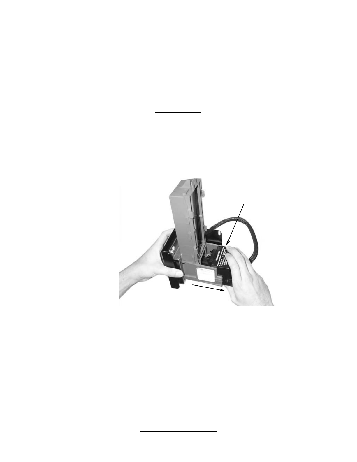
C.) Pull Tab forward and lift Bill Storage Box. (Fig. 11) Remove bills.
D.) Return empty Bill Storage Box.
REMOVING BILL
VALIDATOR
From time to time it may be necessary to remove the Bill Validator for cleaning and clearing jams.
1. To remove the Bill Validator.
A.) Unlock and open the Front Door, unplug vendor.
B.) Remove the Coin Tray, and pull the Vertical Shelf out.
C.) Pull Tab forward and lift Bill Storage Box.
D.) Disconnect Bill Validator from Wiring Harness.
E.) Remove the three (3) Mounting Nuts. (Fig. 11)
F.) Remove Bill Validator.
CLEARING JAMS
It is possible that a torn or damaged bill can jam within the Bill Validator,
putting it out of service.
1. To Clear a Jam.
A.) Remove Bill Validator as above.
B.) Press Tab on bottom of Bill Validator, and pull Lower Housing free. (Fig. 12)
C.) Remove Jam, and reassemble.
CLEANING
It is recommended that you clean your Bill Validator frequently to keep it in order. How frequently and how thoroughly you clean
it will depend on the amount of traffic your vendor serves. Cleaning the Bill Validator can correct problems with service. There
are three levels to the cleaning process. Cleaning with a Cleaning Card, cleaning the Optics, and washing the Lower Housing.
1. Cleaning with a Cleaning Card, will perform a basic clean. The vendor does not need to be opened. One (1) Cleaning Card is
provided with your vendor, but more can, and should, be purchased. Seaga Manufacturing recommends CLEAN TEAM cards
that can be obtained online at www.cleanteam.com or by calling 1-800-888-8830.
A.) Insert the cleaning card in the same manner you would a regular
dollar bill, the card will be rejected.
B.) Repeat once. Do not reuse the card.
2. Cleaning the Optics is the second level of cleaning. You will need cotton swabs (Q-tips), and a mild soap and water solution.
A.) Remove the Bill Validator as described earlier in the manual.
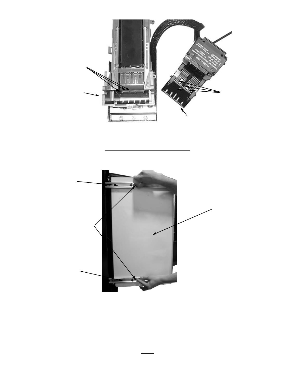
B.) Remove the Lower Housing. There are three (3) Clear Lenses on the
Lower Housing and three (3) Red Lenses inside the Bill Validator. (Fig. 13)
C.) Swab the lenses with the solution, and reassemble.
3. Washing the Lower Housing is recommended at least once per year. You will need a mild soap and water solution.
A.) Remove the Bill Validator as described earlier in the manual.
B.) Remove the Lower Housing.
C.) Moisten the cloth. You will want the cloth moist, but not dripping.
D.) Wipe down the Lower Housing and the inside of the Bill Validator and reassemble.
VERTICAL
SHELF REMOVAL
1. To Remove the Vertical Shelf.
Press Tab
and Pull
Figure 12 Lower Housing Removal
Lower Housing
Page 12
A.) Unlock and open the Front Door, unplug vendor.
B.) Pull the Vertical Shelf out completely.
C.) Disconnect Wiring Harness.
D.) Push Tabs in both Tracks up, (Fig. 14) and pull Vertical Shelf free.
COMMON QUESTIONS
AND ANSWERS
Q: Coin Validator will not accept coins.
A: Lenses may be dirty.
Coins may be damaged or worn.
Wire Harness may not be connected properly.
Coin Validator may not have power.
Q: Optional Bill Validator will not accept bills.
A: Stacker may be full.
There may not be enough coins in the Coin Validator.
Wire Harness may not be connected properly.
Bill Validator may not have power.
LOCK
Your Elite Beverage Vendor has one Lock, more commonly known as a "T" handle lock. This Lock is different from that of the
Figure 13 Lens Cleaning
Red
Lenses (3)
Clear Lenses
(3)
Lower Housing
Bill Validator
Figure 14 Vertical Shelf Removal
Push Tabs
up and pull
Shelf free
Track
Vertical Shelf
Track
Page 13
Elite Snack Vendor in that it has a Threaded Stud that screws into the Cagenut. To unlock the Front Door, insert key and turn
clockwise ¼ turn. When unlocked the "T" of the Lock will pop out from the vendor. Turn the Lock counter-clockwise until the Front
Door opens. To lock, push Front Door closed and turn Lock clockwise until the Gasket is firmly engaged. Note: Do not over tighten, as you could damage the Lock and Gasket.
ELECTRICAL
CONNECTION
The Elite Beverage Vendor requires one 120 VAC grounded outlet for each vendor(s).
Elite Beverage Vendor 120 Volts 4 Amps
TEMPERATURE CHECK
Once your vendor is unboxed you will need to plug in your vendor and allow the vendor to come to operating temperature. We
recommend that you perform this check prior to mounting the vendor to the Elite Snack Combo. It will take about 24hrs for the
vendor to reach operating temperature of 38º- 45º. Temperature fluctuation is normal, and will depend upon your local climate.
Note: Never lay your vendor on its side. To adjust the temperature, turn the Adjustment Slot Counter (1/8" at a time) clockwise
to a colder setting.
Elite Beverage Vendor
HFBV
Wiring Harness Plug
Front Door
Display Windows (5)
Lock
Product Door
(Interior view with
Front Door open)
Serpentine Product Chutes (5)
Display Panel (back)
Driver
Motors (5)
Product Door (back)
Pre-Cool Area
Vend Area
Lock
Cagenut
Section 3
ELITE BEVERAGE VENDOR
Page 14

MOUNTING
Your Elite Beverage Vendor (HFBV) can be mounted to the Elite Snack Vendor to form the Elite Combo.
The vendor comes with mounting hardware. You will need tools for mounting.
1. To Mount to the Elite Snack Vendor.
A.) Unplug both vendors.
B.) Set Elite Snack Vendor on top of HFBV, mating the Wiring Harness
Plug to the opening in the bottom of the Elite Snack Vendor.
CAUTION: Be careful not to damage the Wiring Harness Plug on top of the HFBV.
C.) Unlock and open the Front Door of the Elite Snack Vendor. The HFBV does not need to be opened.
(The following is to be done within the Elite Snack Vendor.)
D.) Remove bottom Product Tray. Pull Product Tray fully forward, keeping it level.
E.) Lift Product Tray to release from the track. Then it can be pulled forward
and lifted out.
CAUTION: The Product Tray Wire Harness will need to be unplugged prior to complete removal of the product tray. The Wiring
Harness is plugged into the inside right-hand side of the vendor. You may need assistance.
F.) Set back of Product Tray into Vend area, steady it with one hand, and disconnect the Wiring Harness.
G.) Attach the Elite Snack Vendor to the top of the HFBV. Insert 4 boltsdown through the vendor into welded nuts in
the top of the HFBV. Tighten. (Fig. 1)
H.) Remove Vertical Shelf per those instructions (Pg. 19)
I.) Connect Wiring harness plug from Elite Snack to HFBV.
J.) Reassemble Vertical Shelf.
PROGRAMMING
AND PRICE SETTING
Once your vendor is mounted and cooling properly you will need to perform an initial Test of all Motors to ensure that the electrical connections are properly made.
1. To Test Driver Motors.
A.) Unlock and open the Front Door to access the Circuit Board, and
enter Service Mode by pressing the Red Service Mode
Button. (Fig. 3)
B.) Cycle through the Service Mode until the display reads "Test".
C.) Press any keypad character other than the DOWN (9) or UP (10) key to
test all motors. No other function can be accessed during the test.
The time this function requires will vary. When complete, display will return to Standard Operating Mode.
Now that you have verified that all motors are functioning properly you will need to set the prices for your product.
1. To Set Prices.
A.) Unlock and open the Front Door to access the Circuit Board, and enter
Service Mode by pressing the Red Service Mode Button. (Fig. 3)
B.) Cycle through the Service Mode until the display reads "Prc". Enter
beverage selection to display current price. Beverage selections are D1 through D5, left to right. Press the
DOWN (9) or UP (10) key to change the price for that selection. Price settings will change in 5 cent increments.
Press "A" to save the new price.
Special Note: We suggest that you always partially fill the vendor with product and perform at least five (5) test vends, and
test vend each selection. Test vends can be performed easily by entering Service Mode and running "Individual Motor Testing".
(See: Keypad and LED Display, Individual Motor Testing.)
LEVELING
Once your vendor is in its new location, you will need to level it to insure proper operation. You will need a level. We recommend a 3ft(1m) level, as it will give a more accurate reading than a small torpedo level. There are threaded Levelers included
with your vendor. These Levelers screw into the bottom of your vendor and can then be adjusted up or down as needed.
DELIVER
Y SYSTEM
The HFBV's Delivery System consists of the Keypad, LED Display, Serpentine Product Chutes, Driver Motors, and the Can Coil.
The customer inserts money and enters their selection on the Keypad. The selection's Driver Motor turns the Can Coil that vends
the product. (Figs. 14 & 15)
There is a sold out switch near the end of each Serpentine Product Chute that will turn on the “Sold-Out” function when it does
not detect product. Note: When the Choose Alternate Selection light flashes, there will be two cans of product remaining in the
Serpentine Product Chute.
LOADING PRODUCT
Product is loaded horizontally at the top of the Serpentine Product Chute. It makes no difference, which way the product lid faces.
Continue to load product until the Serpentine Product Chute is full. Each Serpentine Product Chute will hold 39 cans.
Page 15
PRODUCT VIEWING AND ADVERTISEMENT
Your Elite Beverage Vendor features "live" product display. This means that your customers will see actual cans of the product your vendor is offering.
1.) Set-Up of "Live" Display.
A.) Unlock and open the Front Door.
B.) Unscrew the two(2) wing nuts, and remove black molded plastic Display Panel.
C.) Load product to correspond with its Serpentine Product Chute.
Note: To present your product in as an attractive and professional manner as possible, do not load any damaged items, and
make sure items are facing forward for easy identification by your customer.
D.) Return the Product Display Panel so that it is pressing against the displayed product, and reinstall the
two (2) wing nuts.
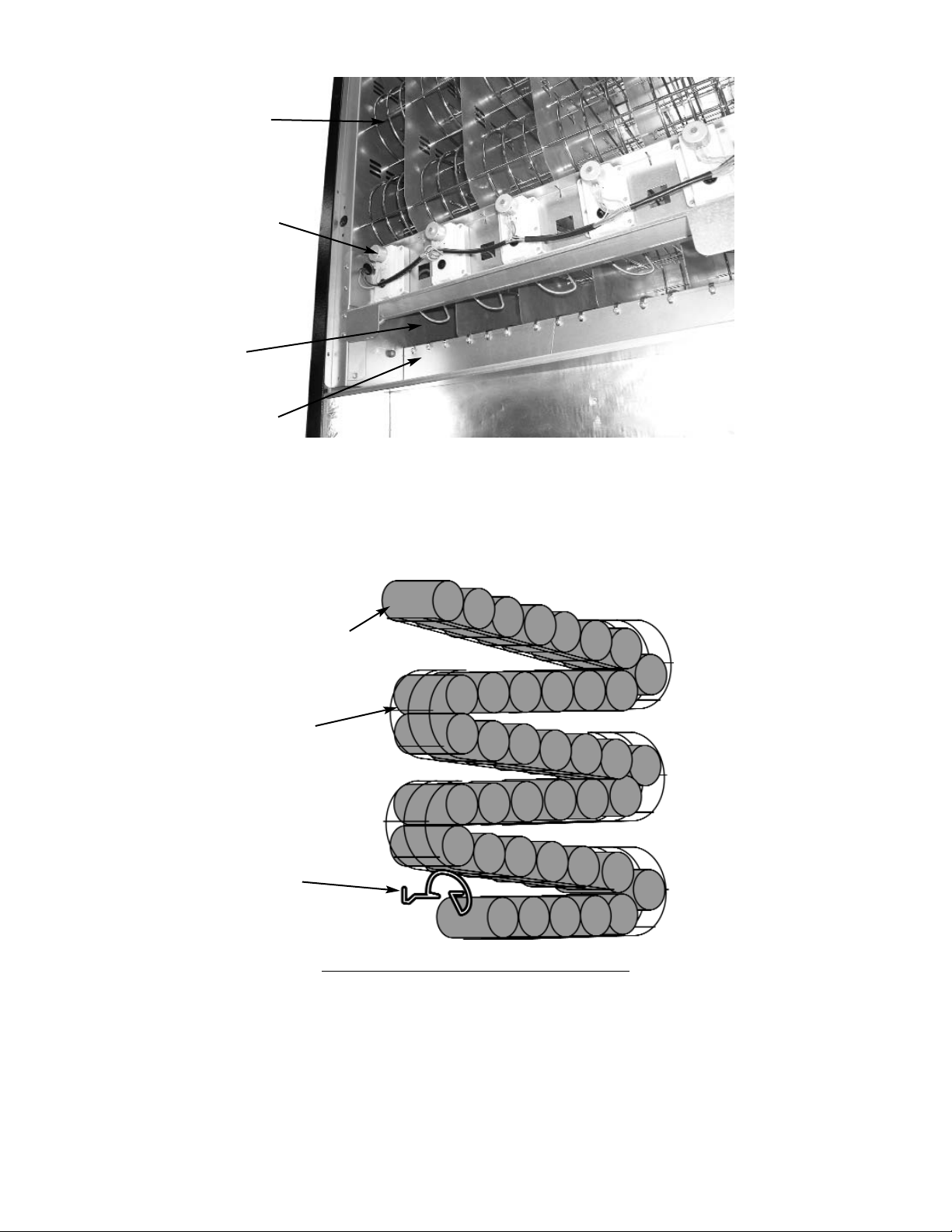
Figure 15 Delivery System
Serpentine
Product Chute
Driver Motor
Can Coil
(shown in
“home” position)
Vend Area
Figure 16 Serpentine Product Chute
Load Product
Can Coil
Serpentine
Product Chute
Page 16
DRIVER MOTORS
Each selection is vended by the action of the Driver Motor. The HFBV has 5 Driver Motors. The Driver Motors are clipped to the
front of the Motor Bracket. (Fig. 16 & Fig. 14)
In the rare event of a jam a Driver Motor may need to be returned to its home position. The home position is when the shaft of
the Can Spiral Coil that is held by the Driver is vertical, with the end of the shaft pointing up.
1. To "Home" a Driver Motor.
A.) Unlock and open the Front door to access the Circuit board, and enter Service Mode by pressing the Red
Service Mode Button (Fig. 3)
B.) Cycle through the Service Mode until the display reads “SLCT”.
C.) Enter the letter and number of the motor you wish to home. The motor will rotate to it’s home position.
2. To Remove a Driver Motor.
A.) Unlock and open the Front Door, unplug vendor.
B.) Unload any product from the Serpentine Product Chute in question.
C.) Depress the top tab on the Driver Motor, rock the Driver Motor forward, and lift the Driver Motor free. (Fig. 8)
D.) Disconnect Wires.
E.) Replace Driver Motor by repeating above steps in reverse order. Note: When inserting the Driver Motor make sure
that the end of the Can Spiral Coil is pointed upward.
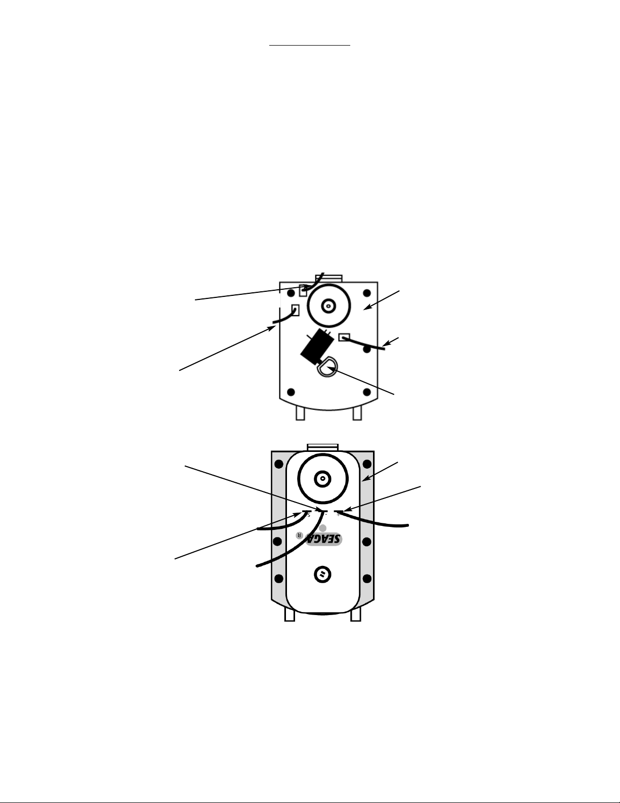
Figure 17 Gray and White Driver Motor
At “Home” switch is
not depressed
Driver Motor
White Wire with
Brown Stripe
Red Wire
Color Wire
Color varies from Left to Right
(From Left)
Blue, Purple, Brown, Gray, White
Figure 17 Black Driver Motor
Driver Motor
White with
Brown Stripe
Wire (S)
Color Wire
(+)
Color varies from
Left to Right
(From Left)
Blue, Purple, Brown,
Gray, White
Red Wire (-)
Page 17
GENERAL NOTES
It is suggested that a toolbox accompany you to each of your locations. Suggested items for this toolbox would include a socket set, (up to a 1/2" socket size suggested) a Phillips and a Standard screwdriver. Additional items would be a soft rag and
perhaps a Black Magic marker. The magic marker is useful in touching up light scratches that may occur to your vendor.
COMMON QUESTIONS AND ANSWERS
Q: Check the Wire Harness on the motor for a loose wire.
Check to see if the motor is jammed or out of home. Home the motor per "Driver Motors".
Q: Motor cycles but can will not drop.
A: Check to see if the can is jammed in the Product Chute.
Check to see if the vendor is level.
Check product for damage, and make sure it is the proper size.
Q: Cans occasionally stick in my Delivery System.
A: This is not uncommon. Some cans may have defects or foreign matter that
may cause them to hesitate, resulting in delayed advancement of product.
Q: How does my HFBV know it's out of product?
A: There is a sold out switch near the end of each Serpentine Product Chute
that will flash the Choose Alternate Selection light when it does not detect
product. Note: When the light flashes, there will be two cans of
product remaining in the Serpentine Product Chute.
Q: The Compressor is running, but the vendor is too warm.
A: Turn the Adjustment Slot Counter (1/8" at a time) clockwise to adjust to a colder temperature.
Make sure that the air flow is not restricted, there should be 10" of clearance on left and rear sides.
Thermostat may not be working properly.
Check for an air leak in the door seal.
Compressor may be undercharged with R134a.
Q: Why doesn't the Compressor cycle?
A: Thermostat may be set too cold. Turn the Adjustment Slot Counter (1/8" at a
time) counter-clockwise to a warmer temperature.
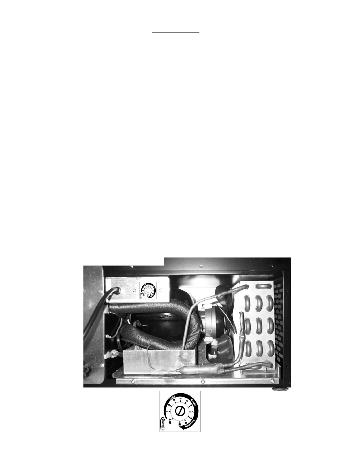
Figure 18 Cooling System
(Rear view)
Page 18

Thermostat may not be working properly.
Compressor may be undercharged with R134a.
Compressor may be defective.
Q: Why is my Evaporator freezing?
A: Check and make sure the Air Circulation Fan is working.
NOTES:
Page 19

 Loading...