


Electronic
Combination Vendor
Operator’s Manual
Seaga Manufacturing, Inc.
700 Seaga Drive
Freeport, IL USA 61032
www.seagamfg.com
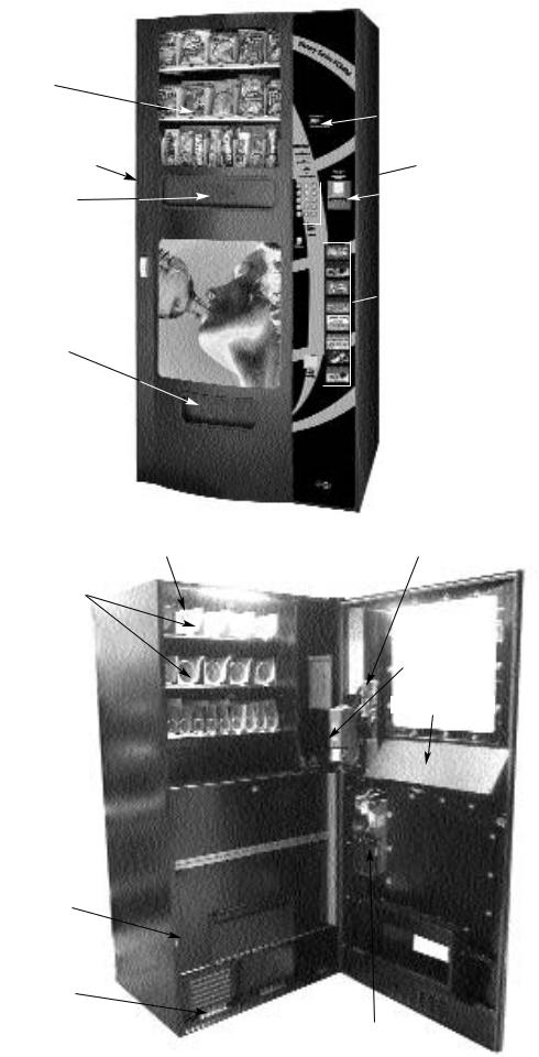
Display
Window
Front Door
Snack
Product Door
Lock 
Beverage
Product Door
(Interior view with Front Door open)
Helix Coils
Product
Trays
(5 Select)
Product Tray
(10 Select) 
Vend Area 
Insulated Door (enclosing Vertical Product Chutes)
Ventilation
Chamber (Must be kept empty)
Combination Vendor
VS3800
 LED Display
Keypad

 Bill Validator
Coin Return

 Button
Beverage
 Flavor Strip
Display
Coin Return

 Door
Door
Circuit Board
Bill Validator
Anti-Theft Door
Coin Validator
The VS3800 Combination Vendor
INTRODUCTION
This manual is divided into four (4) main sections, General, Snack, Payment Systems, and Beverage.
IMPORTANT NOTICES
Your vendor is intended for indoor use only.
Your vendor must be set on a level, well -supported location.
Your vending machine has two (2) power cords. Both must be plugged into gain full use of your vending machine.
Leave at least 6" between the back of the vendor and wall.
Condenser cooling air is taken in the front and exhausted out the back. Always unload vendor before transporting it.
Do not load your vendor with disfigured or damaged product.
Temperature is factory set. Allow your vendor(s) to operate for twenty-four (24) hours before attempting any adjustments.
Section 1
COMBINATION GENERAL INFORMATION
LOCK
Your Combination Vendor has one Lock, more commonly known as a "T" handle Lock. To unlock the Front Panel, insert key and turn clockwise ¼ turn. When unlocked the "T" of the Lock will pop out from the vendor. Turn ¼ turn clockwise to open Front Panel. The Key can be removed once the Lock has been unlocked.
LEVELING
Once your vendor is in its new location, you will need to level it to insure proper operation. We recommend that you use a 3ft (1m) level, as it will give a more accurate reading than a small torpedo level. There are threaded Levelers screwed into the bottom of your vendor that can be adjusted up or down as needed.
|
ELECTRICAL CONNECTION |
The Combination Vendor requires one (2) 120 VAC grounded outlets. |
|
Combination Vendor 120 Volts |
4 Amps |
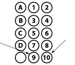
KEYPAD AND LED DISPLAY
The Keypad (Fig. 1) is a touch sensitive operation. Light pressure will be necessary to activate each number or letter. The vendor's Keypad is used by the customer to make their selection, and by the operator to set and test many functions of the vendor. The LED Display shows the customer the amount of money entered into the vendor, and the cost of their selection, it shows the operator the Service Mode functions for setting and testing the various functions of the vendor.
Figure 1 Keypad Layout
Down (in
Service Mode)
E
1. To Access Operator Functions:
A.) Unlock and open the Front Door to access the Circuit Board, and enter Service Mode by pressing the Red Service Mode
Button. (Fig. 2)
Up (in Service
Mode)

Figure 2 Service Mode Button
(Circuit Board inside Front Door)
Wire
Harness
Red Service
Mode Button
Bill Validator
NOTE: when plugging in wire harnesses after servicing, be aware that the side of the wire harness plug that shows silver connectors always face the outside edge of the circuit board or see below for color chart.
The following information is repeated, for your convenience, on a sticker within the vendor.
SERVICE MODE
The Service Mode is entered and exited by pressing the Red Service Mode button on the Circuit Board. All Service Mode functions are cycled and selected by pressing the DOWN (9) and UP (10) keys. If no action is taken within 20 seconds the display will return to Standard Operating Mode.
MOTOR COUNT("Cnt")-displays the total count of motors available in this vendor.
Enter Service Mode. Cycle through the Service Mode until the display reads "Cnt". Press any keypad character other than the DOWN (9) or UP (10) key and the controller will display the motors it recognizes. The total number of motors should equal the total number of selections.
BILL ESCROW("ES")-optional setting that when ON will return the bill to the customer on demand, when OFF the vendor will return coins to the customer.
Enter Service Mode. Cycle through the Service Mode until the display reads "ES". Press any keypad character other than the DOWN (9) or UP (10) key to turn this mode ON ("ES y") or OFF ("ES n"). Press “A” to save the new setting.
MULTI-VEND MODE("UL")-optional setting that when ON allows more than one vend to be performed, provided there is still credit remaining.
Enter Service Mode. Cycle through the Service Mode until the display reads "UL". Press any keypad character other than the DOWN (9) or UP (10) key to turn this mode ON ("UL y") or OFF ("UL n"). Press “A” to save the new setting.
FORCE-VEND MODE("FC")-optional setting that when ON requires a purchase once credit has been deposited.
Enter Service Mode. Cycle through the Service Mode until the display reads "FC". Press any keypad character other than the DOWN (9) or UP (10) key to turn this mode ON ("FC y") or OFF ("FC n"). Press “A” to save the new setting.
BEVERAGE SOLD-OUT MODE("Can")-optional setting that when ON operates sold-out function for this vendor, and will display "Sold Out" when selection is empty.
Enter Service Mode. Cycle through the Service Mode until the display reads "Can". Press any keypad character other than the DOWN (9) or UP (10) key to turn this mode ON ("Can y") or OFF ("Can n"). Press “A” to save the new setting.
TEST ALL MOTORS("Test")-allows user to test all motors in your vendor.
Enter Service Mode. Cycle through the Service Mode until the display reads "Test". Press any keypad character other than the DOWN (9) or UP (10) key to test all motors. No other function can be accessed during the test. The time this function requires will vary. Display will return to Standard Operating Mode.
INDIVIDUAL MOTOR TESTING("Slct")-allows user to individually test each motor in this vendor.
Enter Service Mode. Cycle through the Service Mode until the display reads "Slct". Enter any selection to test it's motor.
(ex. A1)
PRICE SETTING("Prc")-allows the user to set individual prices for each motor or item loaded in your vendor.
Enter Service Mode. Cycle through the Service Mode until the display reads "Prc". Standard selections are Snack: A1A5, B1-B5, C1-C10, and Beverage: D1-D8. Enter any selection to display current price. (ex. A1) Press the DOWN (9) or UP (10) key to change the price for that selection. Price settings will change in 5 cent increments. Press "A" to save the new price.
CASH HISTORY("Cash")- displays total cash count.
Enter Service Mode. Cycle through the Service Mode until the display reads "Cash". Press any keypad character other than the DOWN (9) or UP (10) key to display the total cash count the vendor has accumulated. This function cannot be
reset to zero.
SALES HISTORY("Sale")-displays total vend count.
Enter Service Mode. Cycle through the Service Mode until the display reads "Sale". Press any keypad character other than the DOWN (9) or UP (10) key to display the total vend count that your vendor has performed. This function cannot be reset to zero.
COIN DISPENSING("Coin")-allows user to manually dispense coins from the Coin Mechanism by coin type.
Enter Service Mode. Cycle through the Service Mode until the display reads "Coin". Pressing keys 1-7 will dispense the lowest through the highest denomination of coins. For American Coin Mechanisms key 1 will dispense nickels, key 2 will dispense dimes, and key 3 will dispense quarters.
Special Note: To avoid customer aggravation, Multi-Vend and Force-Vend should NOT be turned on at the same time.
GENERAL NOTES
It is suggested that a toolbox accompany you to each of your locations. Suggested items for this toolbox would include a socket set, (up to a 1/2" socket size suggested) a Phillips and a Standard screwdriver. Additional items would be a soft rag and perhaps a black marker. The marker is useful in touching up light scratches that may occur to your vendor.
Section 2
COMBINATION SNACK SECTION
DELIVERY SYSTEM
The Snack Delivery System of your Combination Vendor consists of the Driver Motors, Product Trays, Product Chutes, and Helix Coils. The customer inserts money and enters their selection on the Keypad. The selection's Driver Motor turns the Helix Coil that vends the product.
 Loading...