


g{x cÜxÅ|âÅ VÉÄÄxvà|ÉÇ
Ambient and Refrigerated models
SERVICE and PARTS MANUAL
700 Seaga Drive, Freeport, IL 61032, U.S.A. |
visit: seagamfg.com email: info@seagamfg.com |
Revision 2012.02.27 |
1 |

INTRODUCTION
Congratulations on the purchase of your vending machine. This vending machine has been designed to give you many years of dependable service. It requires little maintenance and is easy to set up and operate.
READ THIS MANUAL COMPLETELY
Your vending machine is designed to operate simply and reliably, but to take full advantage of your vendor, please read this owner’s manual thoroughly. It contains important information regarding installation and operations, as well as a brief trouble-shooting guide.
EQUIPMENT INSPECTION
After you have received your vendor and have it out of the box, place it on a secure surface for further inspection. Note: Any damages that may have occurred during shipping must be reported to the delivery carrier immediately. Reporting damages and the seeking of restitution is the responsibility of the equipment owner. The factory is willing to assist you in this process in any way possible. Feel free to contact our Customer Care Department with questions you may have on this process.
It is important that you keep the original packaging for your vending machine at least through the warranty period. If your machine needs to be returned for repair, you may have to purchase this packaging if it is not retained.
Once you have your vendor located, we suggest that you keep this manual for future reference, or you can view this manual online at www.seagamfg.com. Should any problems occur, refer to the section entitled “COMMON QUESTIONS AND ANSWERS”. It is designed to help you quickly identify a problem and correct it.
For Service and Customer Care: |
For Service and Customer Care: |
|
8:30 a.m. - 4:00 p.m. CST. Mon thru Fri |
9:00 a.m. - 5:30 p.m. Mon thru Fri |
|
815.297.9500 ext 160 |
+44(0)1492 |
874010 |
815.297.1758 Fax |
+44(0)1492 |
874644 Fax |
email: customercare@seagamfg.com |
email: info@seaga.co.uk |
|
Seaga Manufacturing, Inc. |
Seaga UK Ltd. |
700 Seaga Drive |
Unit 8, Caebach, Off Builders Street |
Freeport, IL 61032 U.S.A. |
Llandudno North Wales LL30 1DR |
www.seagamfg.com |
www.seaga.co.uk |
Revision 2012.02.27 |
2 |

SECTION 1 SPECIFICATIONS
US Version, 110 V
Specifications |
|
4 Wide |
|
|
5 Wide |
|
SP 432 |
SP 430D |
SP 735R |
SP 540 |
SP 536D |
SP 536R |
|
|
Ambient |
Refrigerated |
Refrigerated |
Ambient |
Refrigerated |
Refrigerated |
Height |
72” |
72” |
72” |
72” |
72” |
72” |
Width |
35” |
35” |
35” |
39” |
39” |
39” |
Depth |
37” |
37” |
37” |
37” |
37” |
37” |
Floor Space |
8.75 Sq. Ft |
8.75 Sq. Ft. |
8.75 Sq. Ft. |
9.75 Sq. Ft. |
9.75 Sq. Ft. |
9.75 Sq. Ft. |
Packing Size |
56.27 Cu. Ft. |
56.27 Cu. Ft. |
56.27 Cu. Ft. |
62.53 Cu. Ft. |
62.53 Cu. Ft. |
62.53 Cu. Ft. |
Voltage (AC) |
110V |
110V |
110V |
110V |
110V |
110V |
Hertz |
60Hz |
60Hz |
60Hz |
60Hz |
60Hz |
60Hz |
Running Amperes |
1Amp. |
8Amp. |
8Amp. |
1Amp. |
8Amp. |
8Amp. |
Watts |
300 Watts |
750 Watts |
750 Watts |
300 Watts |
750 Watts |
750 Watts |
Refrigerant Type |
- |
134a |
134a |
- |
134a |
134a |
Refrigerant Charge |
- |
300 Grms. |
300 Grms. |
- |
300 Grms. |
300 Grms. |
Shipping Weight |
470 lbs. |
703 lbs. |
698 lbs. |
528 lbs. |
764 lbs. |
721 lbs. |
UK Version, 220 V
Specifications |
|
4 Wide |
|
|
5 Wide |
|
SP 432 (F) |
SP 430D(F) |
SP 735R(F) |
SP 540(F) |
SP 536D(F) |
SP 536R(F) |
|
|
Ambient |
Refrigerated |
Refrigerated |
Ambient |
Refrigerated |
Refrigerated |
Height |
183 cm |
183 cm |
183 cm |
183 cm |
183 cm |
183 cm |
Width |
89 cm |
35” 89 cm |
89 cm |
99 cm |
99 cm |
99 cm |
Depth |
93 cm |
93 cm |
93 cm |
93 cm |
93 cm |
93 cm |
Floor Space |
0.812 S Mtr |
0.812 S Mtr |
0.812 S Mtr |
0.905 S Mtr |
0.905 S Mtr |
0.905 S Mtr |
Packing Size |
1.59 Cu Mtr |
1.59 Cu Mtr |
1.59 Cu Mtr |
1.77 Cu Mtr |
1.77 Cu Mtr |
1.77 Cu Mtr |
Voltage (AC) |
220V |
220V |
220V |
220V |
220V |
220V |
Hertz |
50Hz |
50Hz |
50Hz |
50Hz |
50Hz |
50Hz |
Running Amperes |
1Amp. |
5Amp. |
5Amp. |
1Amp. |
5Amp. |
5Amp. |
Watts |
300 Watts |
750 Watts |
750 Watts |
300 Watts |
750 Watts |
750 Watts |
Refrigerant Type |
- |
134a |
134a |
- |
134a |
134a |
Refrigerant Charge |
- |
350 Grms. |
350 Grms. |
- |
350 Grms. |
350 Grms. |
Shipping Weight |
317 kg |
319 kg |
317 kg |
239 kg |
347 kg |
327 kg |
PHYSICAL CHARACTERISTICS
Revision 2012.02.27 |
3 |

|
Finish |
: |
Powder Coat paint |
|
Number of Trays |
: |
6 Standard |
ENVIRONMENT |
|
|
|
|
Location Environment: |
|
Indoors only |
ELECTRICAL REQUIREMENT
US version requires one (1) 120 VAC 12 Amps grounded outlet. UK version requires one (1) 220 VAC 12 Amps grounded outlet.
STANDARD COIL CONFIGURATION
Subject to change without notice.
|
Revision 2012.02.27 |
4 |
|
|
|
CAUTION: Certain procedures described in this manual require that voltage be on in the machine. Only trained personnel should perform these functions. Use extreme caution while performing the procedures marked with the voltage symbol shown here:
CAUTION: Certain procedures described in this manual require a qualified, trained technician to perform the particular task at hand. These procedures will be marked with the attention symbol shown here:
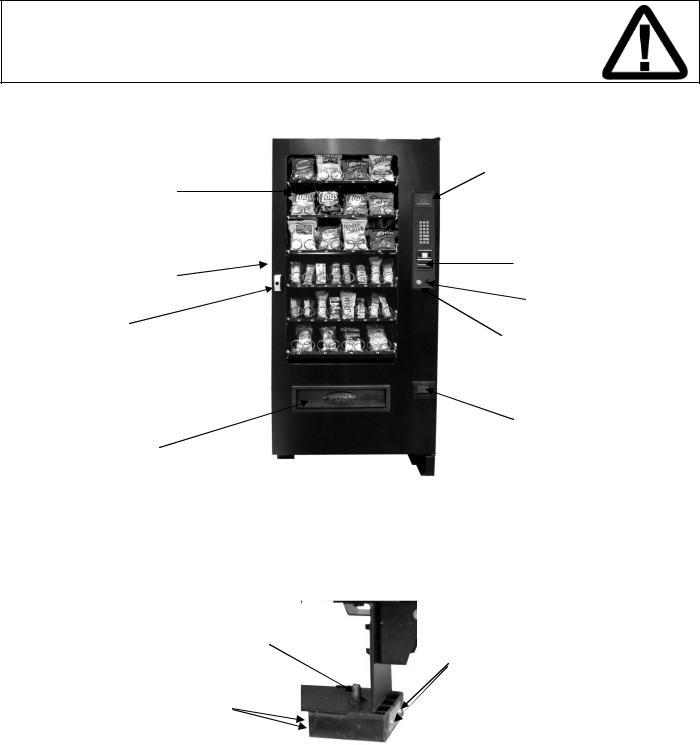
Fig. 1
Exterior View (SP432 4-Wide Snack Machine Shown)
VFD Display
Display Window
 Key Pad
Bill Validator
Front Door
Coin Slot
Lock
Coin Return
Button
Coin Return
Door
Product Door
Protective shipping guards (Fig. 2) were installed on the leveling legs at the factory. Once the machine is placed near its final location the protective shipping guards may be removed. To remove the shipping guard, unscrew the leveling leg from the bottom until the guard is loose – a few turns only. The guard is held together with four phillips head screws and two brackets. Remove the screws and the guard will split in half for removal.
Fig. 2
Leg Leveler
Screws
Screws
 Protective Guard
Now place the machine into its final location. Using a level on the top of the machine, adjust the five leveling legs, if necessary, for proper level both side to side and front to back. A good point to keep in mind is the shorter the leveling legs are kept to achieve proper leveling the more stable the machine will be.
Revision 2012.02.27 |
5 |

Proper leveling is also necessary to allow easy opening and closure of the vending machine door and to insure proper vending operation.
Fig. 3
Leg Leveler
Interior View
Fig. 4
Refrigerated model, modular refrigeration unit.
Refrigeration
Power Switch
Temperature
Sensor
Evaporator Fans
SECTION 2
Control Board
and Brown
Service Mode
Button
Display Board
Red Main
Power Switch
Door Wire
Harness
INSTALLATION
|
CAUTIONS |
Revision 2012.02.27 |
6 |

Your vendor is intended for indoor use only.
Your vendor must be set on a level, well-supported location.
Always unload vendor before transporting it.
Remove all wire ties and protective sheeting prior to vending.
CAUTION!
Procedures marked in this manual with the symbol shown to the left require power to the machine, which means that there is a shock hazard.
CAUTION!
It is important that this machine is hooked up to the proper voltage. Verify the voltage before connecting the machine to a wall outlet.
CAUTION!
Different countries may have different power arrangements. Insure that the machine is properly grounded before operating.
CAUTION!
If the power cord is damaged, it must be replaced by the manufacturer, authorized service agent or a similarly qualified person to avoid electrical hazards.
ATTENTION!
This vending machine is very heavy. Ensure that sufficient personnel are available for lifting or transporting the machine. Use proper lifting procedures and equipment.
CAUTION!
Certain components of this machine are sensitive to static electricity. Precautions for handling sensitive devices should be observed when handling these items.
ATTENTION!
Refrigerated models need air flow. Leave at least 6” between the back of the vending machine and the wall. Condenser cooling air is taken in the bottom and exhausted out the back of the machine. Clean the condenser once every two weeks or more often for highparticle locations.
DOOR CLEARANCE
Please leave 7” clearance on the right side of the machine for the door to open and extend past the cabinet side. See clearance requirements above for refrigerated units.
Revision 2012.02.27 |
7 |
LOADING PRODUCTS
To present your product in as an attractive and professional manner as possible, do not load any damaged items, and make sure items are facing forward for easy identification by your customer.
Note: The size of the item being vended must be larger than the Helix Coil, but smaller than the Product Chute, to vend correctly. Never force an oversized item into the Helix Coil or Product Chute, nor attempt to vend an item that is smaller than the Helix Coil as this will create problems and deter customers. (Fig.1)
1. To Load Product:
A.) Use the release latches and pull the desired Product Tray all of the way
forward. Product Tray will tilt down or can be removed and placed on the floor or a table.
Note: Pull out only one (1) Product Tray at a time.
B.) Place product in proper size Helix Coil. Note: Bottom of product must rest on the Product Tray and not on the Helix Coil. (Fig. 12) Load each
Product Chute from front to back. Note: Do not leave any spaces between items. C.) Once Product Tray is loaded, lift the front of the tray to level and push it
back in. Repeat above steps until all Product Trays are fully loaded.
D.) After loading the product, if you have removed the tray to do so, place the
Tray in the cabinet by aligning the wheels in the guide rails. Clear the wire harness To the side so that it is not interfering with the tray below.
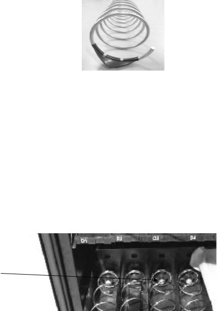
To increase the length of the Helix Coil, white plastic Product Pushers can be snapped on the end. A supply of Product Pushers are provided in the vendors hardware bag.
Special Note: We suggest that you always partially fill the vendor with product and perform at least five (5) test vends. Test vends can be performed easily by entering Service Mode and running "Individual Motor Testing". (See: Keypad and LED Display, Individual Motor Testing.)
Fig. 5
Correct – load product between Helix
Coils, resting Incorrect on the product
tray.
Helix Coil
Product Tray 
Columns
PRODUCT PUSHERS
Product pushers assist in moving the top of the product forward while it is being vended on the bottom, helping it fall smoothly from the shelf. Product pushers are also good for products that have the wrapper flaps on the ends of the package. Packaging such as this benefits from the extra momentum from the product pushers to keep the flaps from hanging up the product on the spiral. The pusher is installed approximately 15mm from the front end of the coil with the tab extending forward (see Fig. 6). Locate the pusher in its proper position, hold it against the coil wire and push the semicircular part around the coil wire. Note: Boxed items will not need a product pusher.
Figure 6 – Product Pusher Installation
Revision 2012.02.27 |
8 |
LOADING BAGGED OR BOXED ITEMS
When vending small bagged items in the 8 or 10 selection trays can be a problem when the products are not loaded properly. The flap edges of some products may get trapped under the spiral and cause the product to “hang up”. It is recommended that the bottom flap of this type of packaging be folded forward and up (Fig. 4) next to the product when loading. This type of packaging also lets the product settle to the bottom, so using the wider spirals is also recommended.
PRODUCT STABILIZERS
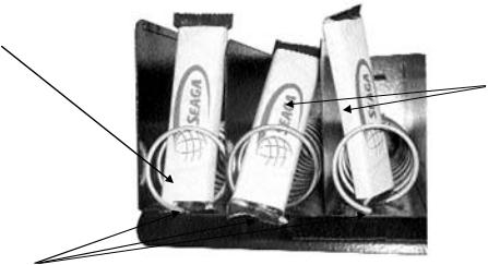
Models with beverage vending can accommodate various sizes of cans and bottles. Product stabilizers have been included with your machine, carefully wrapped, and inserted into the cabinet. Product stabilizers are not absolutely necessary, but do assist the product in several ways: 1.) They present the product in an upright manner, which attracts more attention and will increase your sales and 2.) They keep the product steady as it moves forward during vend cycles.
To install the product stabilizers for beverage vending, first pull out one of the beverage trays. Note the silver tab at the back of the tray, inside the coil (Fig. 7).
Fig. 7 – Product Stabilizers
Silver Tab
The product stabilizers (one for each selection) should be slid inside the coil and the silver tab at the back of the tray should be inserted into the slot on the end of the platform. Note that there are two slots at the end of the platform; the rear-most slot should be used for this application. (Fig. 8)
Fig. 8 – Product Stabilizers
Revision 2012.02.27 |
9 |

Installed
Installed, side view.
Installed, Front View
Installed, Top View
LOCK
Your vendor has one Lock, more commonly known as T-handle lock. To unlock the front door, insert key and turn clockwise ¼ turn. When unlocked the ‘T’ of the Lock will pop out from its base. Turn the ‘T’ 15 to 20 times counter clock wise to unlock the door. To Lock the door turn the ‘T’ handle clockwise 15 to 20 times and then push the ‘T’ inside the Lock to lock the door. Key can now be removed. Note: Do not over-tighten when locking – this could strip the threads and damage your machine.
REFRIGERATION
If you purchased a refrigerated model, please see special information throughout the manual regarding refrigeration, settings and other information. The refrigeration system consists of Compressor, Relay circuit, Accumulator, condenser, condenser fan, evaporator, evaporator fans and air duct. The entire refrigeration system is modular and has a separate internal power cord, which is plugged in on the plug point provided at the bottom area below the last tray. The power switch has to be turned ON in order to start up the refrigeration system. There is a door switch that controls the refrigeration system ON and OFF condition. When the door is opened, the door switch is not depressed and the refrigeration system shuts OFF. When the door is closed, the switch is activated and the evaporator fans starts turning. There will be a delay before compressor starts running after the door closure.
There is a vent on the cabinet back to blow the air from condenser. The inlet vent is at the bottom of the cabinet in front of the condenser. The condenser has to be cleaned regularly. The recommended frequency is once every two weeks. There are 6 clips around the front of the refrigeration module that has to be un-hooked in order to remove the front door of the refrigeration module. This will provide the access to the condenser. Either using fin-comb or a brush, clean the lint in between the condenser fins. Note: Be careful not to bend the fins – this could restrict airflow and damage your machine.
The compressor and the relay circuit, condenser fan motor and drain pan can be accessed in the same manner by removing the front door. The refrigeration system has to be unplugged and the module has to slide completely outside in order to gain access to these components.
SECTION 3 |
OPERATION |
Revision 2012.02.27 |
10 |
DISPLAY
The VFD Display (Fig. 9) is a 2 x 20 Text Display. The display shows the customer the amount of money entered into the vendor and the cost of their selection among other information as programmed. It shows the operator the Service Mode functions for setting the various functions of the vendor.
Fig. 9
SERVICE MODE
|
Sales mode keypad |
Four Service mode Button of keypad |
||
|
|
|
Navigation of the Service Mode Menu |
|
|
|
|
|
|
|
Button |
|
Definition |
|
|
↑ Button |
This key is used to increase a numeric value, or move forward through the |
|
|
|
|
|
various service mode functions. |
|
|
|
|
|
|
|
↓ Button |
This key is used to decrease a numeric value or move backwards through |
|
|
|
|
|
the various service mode functions. |
|
|
|
|
|
|
|
F Button |
This key is used to confirm, accept, or enter into a service mode function. In |
|
|
|
|
|
the Test Key pad Mode it displays a ‘0’ Key on the VFD |
|
|
G Button |
This key is used to EXIT SERVICE or LEAVE a service mode function. |
|
|
|
|
|
Entering Service Mode |
|
Revision 2012.02.27 |
|
11 |
|
|
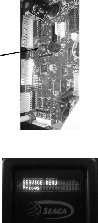
To enter into service mode open the vendor door and Press the Brown Menu Service Mode Button (Fig. 10). After pressing the Service mode switch the controller will beep twice and the display will change to show “Service Menu” on the first line and “Prices” on the second line (Fig. 11). At this time you can use the keypad on the front of the machine to move through the various service mode MENUS.
Fig. 10 - Service Mode Button
Brown MENUS Service
Mode Button
Fig. 11 – VFD Display while in Service Mode. The Prices menu is the first sub-menu.
Revision 2012.02.27 |
12 |

Exiting service mode
The controller will remain in service mode as long as the user keeps using the keypad to move through the various service mode MENUS. The controller will automatically exit service mode and return to sales mode if any of the following occur:
1)The user is inactive for more than 3 minutes
2)The user presses the EXIT key (G).
When service mode is exited the beeper will sound twice and the installed firmware version will be shown on the display for three seconds, then the controller will revert to sales mode.
Service mode MENUS
The chart below shows the sub-menus while in Service mode:
PRICES SUB-MENU
The Prices sub-menu allows you to set prices in three different ways – Set ALL, Set ONE, Set Tray. Set ALL will allow you to set all of selections in the machine to the same price. Set ONE will allow you to set one individual selection of your choosing. Set Tray will allow you to set an entire tray to the same price.
Using these available options will save you time – if the majority of your price is, for example, set at $1, use the Set ALL sub-menu to set all prices to $1. You can then go back and set individual prices for certain selections as needed.
|
|
|
Enter (F) |
|
Enter (F) |
|
||
|
Revision1. |
2012Prices.02.27 |
|
1. 1 Set ALL (Main) |
|
13 |
1.1.1 Enter Price |
Enter (F) |
 Loading...