


SS2000 |
SS4000 |
SS2000 F |
SS4000 F |
Operator’s Manual
1
The Space Saver Automatic Series Vendor
This is a User Manual for SS2000/2000F/4000/4000F Space Saver Automatic Series Vendors. The SS2000 is a non-refrigerated Snack Vendor, whereas SS4000 is a Combo model which includes a refrigerated Beverage Can Vendor. The Standard models are for operation in the North American markets where as the [F] versions are intended for the European and U.K markets
This Operator’s Manual is divided into four (4) main sections. These are a Brief description of Space Saver Automatic series Vendor, Service Mode, Money Mechanisms and Beverage Can vending unit.
IMPORTANT NOTICES
Your vendor (s) are intended for indoor use only
Your vendor (s) must be set on a level, well supported location. Always unload vendor before transporting it.
Remove the plastic cable ties from each helix coil.
Remove any protective sheets from under the Helix coil support plates before loading the vendor.
Do not load your vendor with disfigured or damaged product.
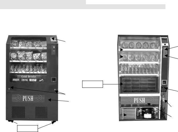
Section 1 Brief Description of your SS series Vendor
( Fig.1 SS4000) |
|
|
|
|
|
( Fig.2 SS4000 ) |
|
|
|
|
|
|
|
||
|
Key Pad |
|
|
|
|
|
|
|
|
|
|
|
|
|
Coin return Button |
|
|
|
|
|
|
|
|
|
|
Product Shelf |
|||||
|
|
|
|
|
|||
|
|
|
|
|
|||
|
|
|
|
|
|
|
|
|
|
|
|
|
|
|
|
|
|
|
|
|
|
|
Coin Insert slot |
|
|
Helix Coils |
|
|
|||
|
|
|
|
|
|
||
|
|
|
|
|
|
|
|
Can Unit
|
|
|
|
|
|
|
Coin Box |
|
|
Locks |
|
|
|
|
|||||
|
|
|
|
|
|
|
|||
|
|
|
|
|
|
|
|
||
|
|
|
|
|
|
|
|
|
|
|
|
|
|
|
|
|
|
||
Front Panel |
|
|
|
Plug& Socket for |
|
||||
|
|
|
Refrigeration deck |
|
|||||
|
|
|
|
|
|
|
|||
|
|
|
|
|
|||||
|
|
|
|
|
|
|
|
|
|
|
|
|
|
|
|
|
|
|
|
|
Refrigeration Deck |
|
|
|
|
|
|
||
|
|
|
Product Door |
|
|
||||
|
|
|
|
|
|
|
|
||
|
|
|
|
|
|
|
|
|
|
|
|
|
|
|
|
|
|
|
|
Levellers
HOW TO LOCK & UNLOCK THE DOOR OF SNACK VENDOR
Your Space Saver Vendor has 2 locks. To open the door, unlock the right side lock by turning the key clockwise. Thereafter open the left side lock by turning the key counter clockwise. The door can now be opened and removed by raising from both the sides and lifting it until the top edge disengages from the Vendor cabinet. (Fig.3)
To lock the door hold both sides of door half way down the door. Engage the top of the door with the Vendor cabinet while keeping the bottom away from the machine. Lower the bottom of the door ensuring that the top of the door remains engaged with the cabinet. Lock the door by turing the left key clockwise and the right key counter clockwise.
3
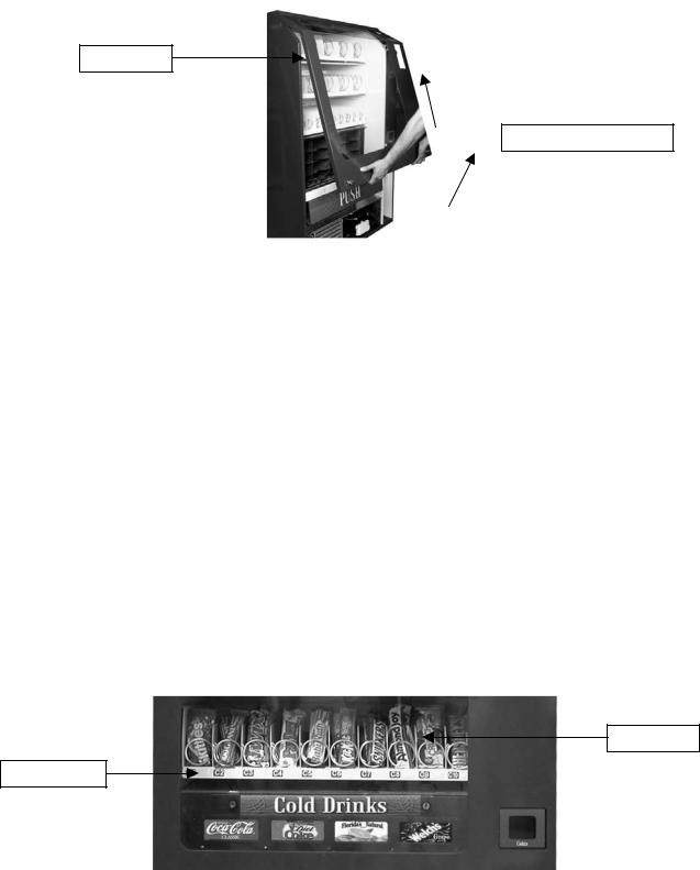
Fig. 3 – Unlocking the front door
Front Door
lift door after unlocking
LEVELING YOUR VENDOR
Once you have installed your vendor in its proper location, you will need to level it to ensure trouble free operation. The vendor is provided with 4 threaded levellers. These can be screwed into the bottom of the vendor and can be adjusted up or down as needed to ensure the machine is leveled properly. (Fig.1)
ELECTRICAL CONNECTION
The SS2000/4000 Snack Vendor requires one 120 VAC 60 Hz grounded outlet
The SS2000 [F]/4000 (F) Snack Vendor requires one 230 VAC 50 Hz grounded outlet
Note: The Mains cable can be coiled back into the left hand rear corner of the vendor. Pull out the cable to the extent necessary before start up.
FIXING PRICE LABELS ON PRODUCT TRAYS
The Price and Product labels supplied with the vendor are to be fixed below the Helix Coil. (Fig.4) The Product Trays must be marked as ‘A’ ,’B’,’C’,’D’ from the top tray downwards. In the case of SS4000 the ‘D’ marking is for the Can Unit. The columns are numbered from the left starting with ‘1’, ‘2’, ‘3’, ‘4’, etc
Fig.4
Column
Labels
KEYPAD AND LED DISPLAY
The Keypad is a touch sensitive operation. Light pressure will be necessary to activate each number or letter. The vendor’s Keypad is used by the customer to make their selection, and by the operator to set and test many functions of the vendor. (Fig. 5)
4

Figure 5
LED Display
Up in Service Mode
When LED is on check price and then insert coins
When LED is on Insert exact change only for a vend
Down in Service
Mode
The LED Display shows the customer the amount of money entered into the vendor, and the cost of their selection, it shows the operator the Service Mode function for setting and testing the various functions of the vendor.
1.To Access Operator Functions:
A)Unlock and open the Front Door to access the Circuit Board, and enter Service Mode by pressing the Red Service Mode Button. (Fig. 6)
CIRCUIT BOARD (Fig. 6)
Shelf Selection
Harness
Red Service
Mode Button
Coin Changer
Harness
Aux. Card Main
Harness
Section 2
SERVICE MODE
The Service Mode is entered and exited by pressing the Red Service Mode Button on the Circuit Board. All Service Mode functions are cycled and selected by pressing the DOWN (9) and UP (10) keys. If no action is taken within 20 seconds the display will return
to Standard Operation Mode.
5
MOTOR COUNT (“Cnt”)- Displays the total count of motors available in this vendor. Enter Service Mode. Cycle
through the Service Mode until the display reads “Cnt”. Press any keypad character other than the DOWN (9) or UP (10) key and the controller will display the motors it recognizes. The total number of motors should equal the total number of selections.
BILL ESCROW (“ES”)- Optional setting that when ON will return the bill to the customer on demand, when OFF the
vendor will return coins to the customer. Enter Service Mode. Cycle through the Service Mode until the display reads “ES”. Press any keypad character other than the DOWN (9) or UP (10) key to turn this mode ON (“ES y”) or OFF (“ES n”).
MULTI-VEND MODE (“UL”)- Optional setting that when ON allows more than one vend to be performed, provided
there is still credit remaining. Enter Service Mode. Cycle through the Service Mode until the display reads “UL”. Press any keypad character other than the DOWN (9) or UP (10) key to turn this mode ON (“UL y”) or OFF (“UL n”).
FORCE-VEND MODE (“FC”)- Optional setting that when ON requires a purchase once credit has been deposited.
Enter Service Mode. Cycle through the Service Mode until the display reads “FC”. Press any keypad character other than the DOWN (9) or UP (10) key to turn this mode ON (“FC y”) or OFF (“FC n”).
BEVERAGE SOLD-OUT MODE (“Can”)- Optional setting that when ON operates sold-out function for this
vendor, and will display “Sold Out” when selection is empty. Enter Service Mode. Cycle through the Service Mode until the display reads “Can”. Press any keypad character other than the DOWN (9) or UP (10) key to turn this mode ON (“Can y”) or OFF (“Can n”).
TEST ALL MOTORS (“Test”)- Allows user to test all motors in your vendor. Enter Service Mode.
Cycle through the Service Mode until the display reads “Test”. Press any keypad character other than the DOWN (9) or UP (10) key to test all motors. No other function can be accessed during the test. The time this function requires will vary. Display will return to Standard Operating Mode.
INDIVIDUAL MOTOR TESTING (“Slct”)- Allows user to individually test each motor in this vendor. Enter Service Mode. Cycle through the Service Mode until the display reads “Slct”. Enter any selection to test it’s motor. (ex. A1)
PRICE SETTING (“Prc”)- Allows the user to set individual prices for each motor or item loaded in your vendor. Enter
Service Mode. Cycle through the Service Mode until the display reads “Prc”. Enter any selection to display current price. (ex. A1) Press the DOWN (9) or UP (10) key to change the price for that selection. Price setting will change in 5 cent increments. Press “A” to save the new price.
CASH HISTORY (“Cash”)- Displays total cash count.
Enter Service Mode. Cycle through the Service Mode until the display reads “Cash”. Press any keypad character other than the DOWN (9) or UP (10) key to display the total cash count the vendor has accumulated. This function cannot be reset to zero.
SALES HISTORY (“Sale”)- Displays total vend count.
Enter Service Mode. Cycle through the Service Mode until the display reads “Sale”. Press any keypad character other than the DOWN (9) or UP (10) key to display the total vend count that your vendor has performed. This function cannot be reset to zero.
COIN DISPENSING (“Coin”)- Allows user to manually dispense coins from the Coin Mechanism by coin type.
Enter Service Mode. Cycle through the Service Mode until the display reads “Coin”. Pressing keys 1-7 will dispense the lowest through the highest denomination of coins. For American Coin Mechanisms key 1 will dispense nickels, key 2 will dispense dimes, and key 3 will dispense quarters.
Special Note: To avoid true customer aggravation, Multi-Vend and Force-Vend should NOT be turned on at same time.
DELIVERY SYSTEM
The delivery system of your SS4000 Series Snack vendor consists of the Keypad, LED Display, Driver Motors, Product Trays Helix Coils and Beverage Can Unit. The customer inserts money and enters their selection on the Keypad. The selected Driver Motor turns the Helix Coil that vends the product.
6
 Loading...