


Scotsman SCCP50MA-1WU, SCCG50MA-1WU, SCCP50MA-1BU, SCCG50MA-1BU, SCCP50MA-1SU Service Manual
...Service Manual for Residential Ice Machine
Models SCCG50 and SCCP50

SCCG50 & SCCP50
Service Manual
Introduction:
This ice machine is the result of Scotsman’s decades of experience as an industry leader in the design and manufacture of both commercial and residential ice machines.
This manual includes the information needed to install, start up and maintain the ice machine. Note any Caution or Warning indicators, as they provide notice of potential hazards. Keep this manual for future reference.
Table of Contents
Specifications . . . . . . . . . . . . . . . |
. . . . . . . . |
. . . . |
. . |
|
Page 2 |
Cabinet Layout . |
|
|
|
|
Page 3 |
Air flow. . . . . . . . . . . . . . . . . |
. . . . . . . . . |
. . . . |
. |
. Page 4 |
|
Water Quality. |
|
|
|
|
Page 5 |
Door Covering. . . . . . . . . . . . . . . |
. . . . . . . . |
. . . . |
. . |
|
Page 6 |
Door Panel Attachment. |
|
|
|
|
Page 7 |
Custom Panel. . . . . . . . . . . . . . . |
. . . . . . . . |
. . . . |
. . |
|
Page 8 |
Door swing change. |
|
|
|
|
Page 9 |
Installation: Water & Drain. . . . . . . . . . . |
. . . . . . . . |
. . . . |
. |
. |
Page 10 |
Gravity Drain. . . . . . . . . . . . . . . . . . . . . . . . . . . . . . . . . . . . . . . . . . . . |
Page 11 |
||||
Electrical. . . . . . . . . . . . . . . . . |
. . . . . . . . |
. . . . |
. |
. |
Page 12 |
Cube Size Adjustment. . . . . . . . . . . . |
. . . . . . . . . |
. . . . |
. |
|
Page 13 |
Harvest Time Adjustment. |
|
|
|
|
Page 14 |
Control Settings. . . . . . . . . . . . . . |
. . . . . . . . . |
. . . . |
. |
|
Page 15 |
Use . |
|
|
|
|
Page 16 |
How to clean the condenser and winterize. |
|
|
|
|
Page 17 |
How to remove scale from the ice making system. |
|
|
|
|
Page 18 |
System Information. |
|
|
|
|
Page 19 |
Water System . . . . . . . . . . . . . . . |
. . . . . . . . |
. . . . |
. . |
|
Page 20 |
Components. . . . . . . . . . . . . . . |
. . . . . . . . . |
. . . . |
. |
. Page 21 |
|
Controller. |
|
|
|
|
Page 22 |
Performance Information. |
|
|
|
|
Page 23 |
Refrigeration System. |
|
|
|
|
Page 24 |
Thermistor Values. . . . . . . . . . . . . |
. . . . . . . . . |
. . . . |
. |
. Page 25 |
|
Service Diagnosis. . . . . . . . . . . . . |
. . . . . . . . . |
. . . . |
. |
. Page 26 |
|
Service Diagnosis. . . . . . . . . . . . . |
. . . . . . . . . |
. . . . |
. |
. Page 27 |
|
Removal and Repair. . . . . . . . . . . . . |
. . . . . . . . |
. . . . |
. |
. |
Page 28 |
Removal and Repair. . . . . . . . . . . . . |
. . . . . . . . |
. . . . |
. |
. |
Page 29 |
Removal and Repair - Cabinet Removal. |
|
|
|
|
Page 30 |
Refrigeration Service. |
|
|
|
|
Page 32 |
June 2008
Page 1

SCCG50 & SCCP50
Service Manual
Specifications
This ice machine is designed to be used indoors, in a controlled environment. It can be used in a wide variety of environmental conditions, but there are limits. Use outside of the listed limitations is misuse and will void the warranty.
Air temperature limits:
The ice machine will operate adequately within the limits, but functions best in temperatures between
70 and 80 degrees F.
•Minimum – 50 degrees F. (10°C)
•Maximum – 100 degrees F. (38°C)
Options:
Door Panel kits: Finished door panels are available from Scotsman for attachment to the machine,
or a custom panel can be made.
Kit Number |
Panel Finish |
Handle Finish |
KDFW |
White |
White |
KDFWS |
White |
Stainless Steel |
KDFB |
Black |
Black |
KDFBS |
Black |
Stainless Steel |
KDFS |
Stainless Steel |
Stainless Steel |
Water temperature limits:
•Minimum – 40 degrees F. (4.5°C)
•Maximum – 100 degrees F. (38°C)
Water pressure limits:
•Minimum – 20 psi (1.4 bar)
•Maximum – 80 psi (5.5 bar)
Because the ice machine is making a food product, the water supply to the ice machine must be potable, or fit for human consumption.
Electrical
•115 volt, 60 Hz. Plug into dedicated 15 amp circuit.
•Power consumption: 275 - 400 Watts. Varies during Freeze and Harvest cycles.
Voltage limits:
•Minimum - 104 volts
•Maximum – 126 volts
Models: All are air cooled (A series began 8/09):
Kickplate Extension: In some situations the leg levelers will be extended enough to become visible. A kit to extend the kickplate over the legs is KKPF.
Cabinet Stability: In some free standing installations it may be prudent to add a bracket that secures the back of the cabinet to a wall. That kit number is KATB.
Drain Conversion:
A gravity drain model can be converted to a drain pump model by installing a drain pump kit. The drain pump kit consists of a drain pump, wiring harness and associated tubing. The kit number is
A39462-021.
Warranty Information
Warranty information is supplied separately from this manual. Refer to it for coverage. In general, the warranty covers defects in materials or workmanship and does not cover corrections of installation errors or maintenance.
•SCCP50MA-1WU – Pump model, white cabinet - discontinued 2013
•SCCG50MA-1WU – Gravity drain model, white cabinet - discontinued 2013
•SCCP50MA-1BU – Pump model, black cabinet - discontinued 2013
•SCCG50MA-1BU – Gravity drain model, black cabinet - discontinued 2013
•SCCP50MA-1SU – Pump model, stainless cabinet, unfinished door
•SCCG50MA-1SU – Gravity drain model, stainless cabinet, unfinished door
•SCCP50MA-1SS – Pump model, stainless cabinet and door
•SCCG50MA-1SS – Gravity drain model, stainless cabinet and door
November 2014
Page 2
SCCG50 & SCCP50
Service Manual
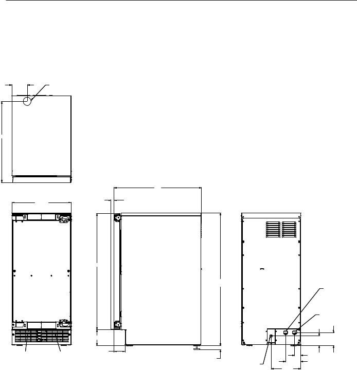
Cabinet Layout
3 7/8" |
FLOOR DRAIN |
|
ACCESS HOLE |
||
|
20 3/8"
|
22" |
|
.75 SHEET METAL DOOR FRONT |
14 7/8" |
.63 MIN.CABINET DOOR |
29 1/4"
33 3/8" MIN.
34 3/8" MAX.
4"
AIR OUT |
AIR IN |
2 3/4" |
1" LEG ADJUSTMENT
(4) PLACES
115 V 3 3/4"
POWER CORD
7 3/8"
DRAIN FLEXIBLE TUBING
3/8 I.D.PUMP MODEL (INCLUDED)
5/8 I.D.GRAVITY MODEL (NOT INCLUDED)
POTABLE WATER INLET 1/4" COMPRESSION FITTING
3 1/4"
2 1/2"
1 1/2"
June 2008
Page 3

SCCG50 & SCCP50 Service Manual
Air flow
The machine takes in room temperature air at the lower right front and forces warm air out the lower left front. Restricting the airflow will adversely affect the ability of the ice machine to make ice.
Control Panel
Ice Making
Area
Warm Air Out Air Intake
Scotsman Ice Systems are designed and manufactured with the highest regard for safety and performance. They meet or exceed the standards of agencies like U.L.
Scotsman assumes no liability or responsibility of any kind for products manufactured by Scotsman that have been altered in any way, including the use of any parts and/or other components not specifically approved by Scotsman.
Scotsman reserves the right to make design changes and/or improvements at any time.
Specifications and designs are subject to change without notice.
June 2008
Page 4

SCCG50 & SCCP50
Service Manual
Water Quality
All water, including potable water supplied by municipalities, contains some impurities or minerals. Water absorbs impurities from the air as rain and/or as it flows through the ground. Some of the impurities are solid particles, these are known as suspended solids, and a fine particle filter will remove them. Other impurities are chemically bonded to the water molecules, and cannot be filtered out, these are called dissolved solids.
Ice made by this machine will have a lower mineral content than the water it was made from. This is due to the method of making ice. Purer water will freeze first in the ice making molds.
The reason for this is that anything dissolved in water lowers the water’s freezing temperature.
This concentrates most of the impurities in the ice machine water reservoir where they may form hard deposits known as scale. The machine dilutes the concentration of minerals by over-filling the reservoir during the harvest cycle (with the excess water flowing down the drain). s. Between
2 and 4 pints of water flow into the unit each cycle. Between 1 and 3.5 pints of that rinses the reservoir and goes down the drain.
Some impurities will inevitably remain, and will stick to the parts in the machine, and will cause malformed ice cubes. Eventually, built up mineral scale can shorten machine life.
To keep the machine operating properly, these impurities or minerals will have to be regularly dissolved by an acid cleaning, using Scotsman Ice Machine Scale Remover. Directions for this may be found in the section under cleaning.
Filters and Treatment
In general, it is always a good idea to filter the water. A water filter, if it is of the proper type, can remove taste and odors as well as particles. Some methods of water treatment for dissolved solids include reverse osmosis, and polyphosphate feeders.
RO Water
This machine can be supplied with Reverse Osmosis water, but the water conductivity must be no less than 10 microSiemens/cm. A reverse osmosis system should include post treatment to satisfy the R.O. water’s potential aggressiveness. Deionized water is not recommended.
Because water softeners exchange one mineral for another, softened water may not improve water conditions when used with ice machines. Where water is very hard, softened water could result in white, mushy cubes that stick together.
If in doubt about the water, contact a local point of use water specialist for recommendations on water treatment.
Installation Overview
The ice machine must:
•be connected to cold, potable water
•be connected to a drain
•be connected to the proper power supply
•be able circulate air through the vents at the front.
Note: Do not build in so that the door is recessed.
June 2008
Page 5

SCCG50 & SCCP50
Service Manual
Door Covering
Door Panel Custom Panel
The ice machine is supplied without a conventional door covering so it can be decorated to the user’s preference. Scotsman offers several coverings including white, black and stainless steel. In addition, a custom built panel can be placed onto the door.
Door Panel Attachment
To attach a Scotsman supplied panel:
Note: If door swing is to be changed, it must be done before panel is attached.
The panel will be held on by 6 sheet metal screws and 2 machine screws.
1.Remove the gasket and retain for later use.
2.If the door panel is stainless steel, remove any plastic covering the stainless steel panel.
3.Place the panel onto the outside of the door, and secure it to the door using two machine screws, located at the left center and right center.
4.Fasten the panel to the door using the 6 sheet metal screws. In the hinge area, use the outermost screw holes.
5.Place the covers over the hinge areas, and secure each cover to the door using a sheet metal screw.
6.Insert hole plug over screw installed in step 5.
7.Return the gasket to its original position.
A custom panel of wood or other material not exceeding 15 lb can be attached to the door. Attachment is from the ice side of the door. Holes are provided in the door for this purpose.
See instructions in information packet to create and attach a custom panel:
June 2008
Page 6

SCCG50 & SCCP50
Service Manual
Door Panel Attachment
Use Upper
Hole at the
Top
Scotsman
 Door Panel
Gasket Machine


Screw
Hole Plug
Use Lower
Hole at the
Bottom
Cover
June 2008
Page 7
SCCG50 & SCCP50
Service Manual
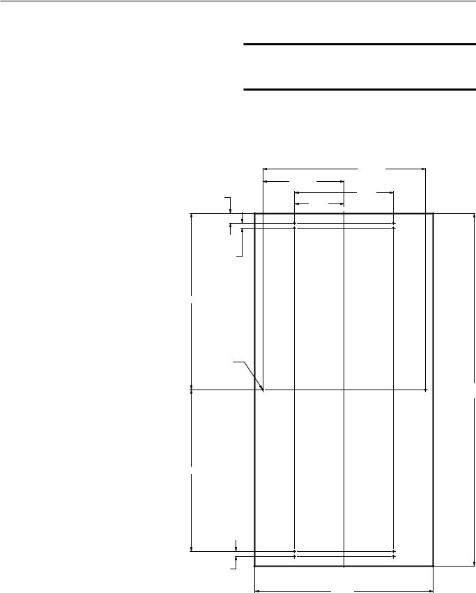
Custom Panel
A custom panel of wood or other material not exceeding 15 lb can be attached to the door. Attachment is from the ice side of the door. Holes are provided in the door for this purpose.
To create and attach a custom panel:
•Panel width: 14 7/8”
•Panel height: Between 29 3/8” and 30 3/8”.
•Panel thickness: 5/8” to ¾”
10. Mount panel to door using wood screws or supplied panel mounting screws.
Note: When installed Ice machine must be adjusted for height to position top of door to desired clearance.
1.Measure overall height of cabinet opening where ice machine will be (floor to bottom of countertop edge).
2.Determine desired kickplate space (from bottom of door to floor). This could be equal to the adjacent cabinet’s kickplate space or another space the user wants.
3.Subtract kickplate space from cabinet opening.
4.Subtract 1/8 or more for clearance space between top of door and bottom of countertop edge from cabinet opening. This is the maximum door length.
5.Cut panel to width.
6.Cut panel to length (cabinet space
- kickplate space - top clearance = length).
7.Determine top of panel.
8.Mark hole locations using drawing on the back of these instructions. Drawing assumes top of panel will be flush with top of door. Measure hole locations from the top of the panel.
9.Drill pilot holes for wood screws.
Use drill stop to prevent drilling through the panel.
|
|
16/9 13" |
|
|
|
32/25 6" |
|
16/13" |
4/1 8" |
||
8/1 4" |
|||
|
|
||
|
32/13" |
|
|
16/11 14" |
|
|
|
Ø |
8/1" |
|
|
TYP. (10) |
|
||
|
|
8/3 30" |
|
|
|
8/3 29" |
|
64/31 13" |
|
|
|
32/13" |
{Centerline} |
||
|
|
||
|
|
8/7 14" |
|
June 2008
Page 8

SCCG50 & SCCP50 Service Manual
Door swing change
Note: Prior models had separate hinge brackets and different directions to change swing.
Moving the hinges allows the door to open from either the left or right side. Change swing before attaching door panel.
To change:
1. Remove innermost screw holding each hinge to cabinet, loosen the other.
Remove
Loosen
2. Slide door to the side and remove from cabinet.
Plug |
||
Cover |
||
|
3. Remove plug and hinge pocket covers from door.
Note: There are either plugs or screws in the holes where the hinges will mount. They must be moved.
4.Remove hole plugs or screws from unit’s new hinge locations, set aside.
5.Move screws loosened in step 1 to opposite location.
6.Install screws or plugs removed in step 4 to the unit’s original hinge location to fill the holes.
7.Remove the upper hinge from the door
and move it to the door’s opposite side, bottom location. Secure using the original screws.
Note: If door panel is attached, it must be removed to access hinge screws and to reverse handle position.
8.Remove the original lower hinge and move it to the door’s opposite side, upper location. Secure using the original screws.
9.Install pocket covers and hole plugs onto door.
10.Attach the door to the cabinet using the original screws.
Installation Notes
Built In Situations: If a finished floor is to be installed in the area after the ice machine has been built in, shims the expected thickness of the floor should be installed under the unit to keep the machine level with the planned floor level.
Installations on a slab: Use a pump model and pump the water to the point of drainage. Pump models will pump 1 story (10 feet) high.
Installations over a crawl space or basement:
Either gravity drain or pump model units may be used, if there is not enough room behind the
machine for a drain/waste receptacle, the drain will have to be below the floor.
Note: When installed in a corner, the door swing may be limited due to handle contact with the wall or cabinet face.
January 2012
Page 9
 Loading...