


CU50
Service Manual
Introduction:
This ice machine is the result of Scotsman’s decades of experience as an industry leader in the design and manufacture of both commercial and residential ice machines.
This manual includes the information needed to install, start up, maintain and service the ice machine. Note any Caution or Warning indicators, as they provide notice of potential hazards. Keep this manual for future reference.
Table of Contents
Specifications . . . . . . . . . . . . . . . . . . . . . . . . . . . . . . . . . . . . . . . . . . |
Page 2 |
Cabinet Layout . . . . . . . . . . . . . . . . . . . . . . . . . . . . . . . . . . . . . . . . . |
Page 3 |
Air flow . . . . . . . . . . . . . . . . . . . . . . . . . . . . . . . . . . . . . . . . . . . . . |
Page 4 |
Water Quality . . . . . . . . . . . . . . . . . . . . . . . . . . . . . . . . . . . . . . . . . . |
Page 5 |
Door Covering . . . . . . . . . . . . . . . . . . . . . . . . . . . . . . . . . . . . . . . . . . |
Page 6 |
Door Panel Attachment . . . . . . . . . . . . . . . . . . . . . . . . . . . . . . . . . . . . . |
Page 7 |
Custom Panel . . . . . . . . . . . . . . . . . . . . . . . . . . . . . . . . . . . . . . . . . . |
Page 8 |
Door swing change . . . . . . . . . . . . . . . . . . . . . . . . . . . . . . . . . . . . . . . |
Page 9 |
Installation: Water & Drain . . . . . . . . . . . . . . . . . . . . . . . . . . . . . . . . . . . |
Page 10 |
Gravity Drain . . . . . . . . . . . . . . . . . . . . . . . . . . . . . . . . . . . . . . . . . . |
Page 11 |
Electrical . . . . . . . . . . . . . . . . . . . . . . . . . . . . . . . . . . . . . . . . . . . . |
Page 12 |
Cube Size Adjustment . . . . . . . . . . . . . . . . . . . . . . . . . . . . . . . . . . . . . |
Page 13 |
Harvest Time Adjustment . . . . . . . . . . . . . . . . . . . . . . . . . . . . . . . . . . . . |
Page 14 |
Control Settings . . . . . . . . . . . . . . . . . . . . . . . . . . . . . . . . . . . . . . . . . |
Page 15 |
Use . . . . . . . . . . . . . . . . . . . . . . . . . . . . . . . . . . . . . . . . . . . . . . . |
Page 16 |
How to clean the condenser and winterize. . . . . . . . . . . . . . . . . . . . . . . . . . . . |
Page 17 |
How to remove scale from the ice making system. . . . . . . . . . . . . . . . . . . . . . . . |
Page 18 |
System Information . . . . . . . . . . . . . . . . . . . . . . . . . . . . . . . . . . . . . . . |
Page 19 |
Water System . . . . . . . . . . . . . . . . . . . . . . . . . . . . . . . . . . . . . . . . . . |
Page 20 |
Components . . . . . . . . . . . . . . . . . . . . . . . . . . . . . . . . . . . . . . . . . . |
Page 21 |
Controller . . . . . . . . . . . . . . . . . . . . . . . . . . . . . . . . . . . . . . . . . . . . |
Page 22 |
Performance Information . . . . . . . . . . . . . . . . . . . . . . . . . . . . . . . . . . . . |
Page 23 |
Refrigeration System . . . . . . . . . . . . . . . . . . . . . . . . . . . . . . . . . . . . . . |
Page 24 |
Thermistor Values . . . . . . . . . . . . . . . . . . . . . . . . . . . . . . . . . . . . . . . . |
Page 25 |
Service Diagnosis . . . . . . . . . . . . . . . . . . . . . . . . . . . . . . . . . . . . . . . . |
Page 26 |
Service Diagnosis . . . . . . . . . . . . . . . . . . . . . . . . . . . . . . . . . . . . . . . . |
Page 27 |
Removal and Repair . . . . . . . . . . . . . . . . . . . . . . . . . . . . . . . . . . . . . . |
Page 28 |
Removal and Repair . . . . . . . . . . . . . . . . . . . . . . . . . . . . . . . . . . . . . . |
Page 29 |
Removal and Repair - Cabinet Removal . . . . . . . . . . . . . . . . . . . . . . . . . . . . |
Page 30 |
Refrigeration Service . . . . . . . . . . . . . . . . . . . . . . . . . . . . . . . . . . . . . . |
Page 32 |
March 2010 |
|
Page 1 |
|

CU50
Service Manual
Specifications
This ice machine is designed to be used in a controlled environment. It can be used in a wide variety of environmental conditions and under limited conditions (see user manual), outdoors, but there are limits. Use outside of the listed limitations is misuse and will void the warranty.
Air temperature limits:
The ice machine will operate adequately within the limits, but functions best in temperatures between 70 and 80 degrees F.
•Minimum – 50 degrees F. (10oC)
•Maximum – 100 degrees F. (38oC)
Water temperature limits:
•Minimum – 40 degrees F. (4.5oC)
•Maximum – 100 degrees F. (38oC)
Water pressure limits:
•Minimum – 20 psi (1.4 bar)
•Maximum – 80 psi (5.5 bar)
Because the ice machine is making a food product, the water supply to the ice machine must be potable, or fit for human consumption.
Options:
Kickplate Extension: In some situations the leg levelers will be extended enough to become visible. A kit to extend the kickplate over the legs is KKPF.
Cabinet Stability: In some free standing installations it may be prudent to add a bracket that secures the back of the cabinet to a wall. That kit number is KATB.
Drain Conversion:
A gravity drain model can be converted to a drain pump model by installing a drain pump kit. The drain pump kit consists of a drain pump, wiring harness and associated tubing. The kit number is A39462-021.
Warranty Information
Warranty information is supplied separately from this manual. Refer to it for coverage. In general, the warranty covers defects in materials or workmanship and does not cover corrections of installation errors or maintenance.
Electrical
•115 volt, 60 Hz. Plug into dedicated 15 amp circuit.
•Power consumption: 275 - 400 Watts. Varies during Freeze and Harvest cycles.
Voltage limits:
•Minimum - 104 volts
•Maximum – 126 volts
Models: There are two models, all air cooled:
•CU50PA-1 – Pump model
•CU50GA-1 – Gravity drain model
March 2010
Page 2

CU50
Service Manual
Cabinet Layout
98.55 |
FLOORAIND |
|
|
|
|
3.88 |
ACCESS HOLE |
|
|
|
|
443.23 |
|
|
|
|
|
17.45 |
|
|
|
|
|
|
|
|
606.68 |
|
|
|
|
|
23.89 |
|
|
|
|
|
566.17 |
|
|
|
|
|
22.29 |
|
|
|
377.95 |
|
40.51 |
|
|
|
|
1.60 |
|
|
|
|
14.88 |
|
|
|
|
|
|
|
|
|
|
|
|
753.24 |
|
|
|
|
|
29.66 |
|
|
|
|
|
|
873.25 |
|
DRAIN |
|
|
|
34.38 |
|
|
|
|
|
|
|
FLEXIBLETUBING |
|
|
|
|
|
3/8D.I.PUMP MODELLUDED)(INC |
|
|
|
|
|
5/8D.I.GRAVITY MODELT INCLUDED)(N |
|
|
|
|
|
POTABLEWATER INLET |
|
|
|
|
|
1/4"COMPRESSIONTTINGFI |
|
|
97.79 |
|
|
82.99 |
|
|
3.85 |
|
|
|
|
|
|
|
3.27 |
|
|
|
|
|
|
|
|
|
|
|
115V |
39.75 |
AIR OUT |
AIR IN |
|
|
POWERCORD |
|
81.28 |
|
1.57 |
|||
|
|
LEG |
|
||
|
|
3.20 |
|
97.16 |
|
|
|
ADJUSTMENT |
62.04 |
||
|
|
|
3.83 |
||
|
|
|
[25.40] |
2.44 |
|
|
|
|
188.98 |
||
|
|
|
1.00 |
|
|
|
|
|
|
7.44 |
|
|
|
|
|
|
March 2010
Page 3
CU50
Service Manual
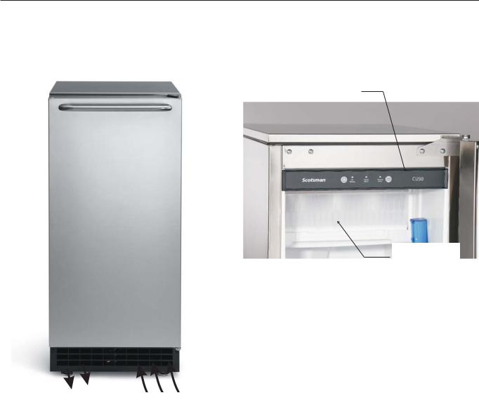
Air flow
The machine takes in room temperature air at the lower right front and forces warm air out the lower left front. Restricting the airflow will adversely affect the ability of the ice machine to make ice.
Control Panel
Ice Making
Area
Warm Air Out |
Air Intake |
|
Scotsman Ice Systems are designed and manufactured with the highest regard for safety and performance. They meet or exceed the standards of agencies like U.L.
Scotsman assumes no liability or responsibility of any kind for products manufactured by Scotsman that have been altered in any way, including the use of any parts and/or other components not specifically approved by Scotsman.
Scotsman reserves the right to make design changes and/or improvements at any time.
Specifications and designs are subject to change without notice.
March 2010
Page 4

CU50
Service Manual
Water Quality
All water, including potable water supplied by municipalities, contains some impurities or minerals. Water absorbs impurities from the air as rain and/or as it flows through the ground. Some of the impurities are solid particles, these are known as suspended solids, and a fine particle filter will remove them. Other impurities are chemically bonded to the water molecules, and cannot be filtered out, these are called dissolved solids.
Ice made by this machine will have a lower mineral content than the water it was made from. This is due to the method of making ice. Purer water will freeze first in the ice making molds. The reason for this is that anything dissolved in water lowers the water’s freezing temperature. This concentrates most of the impurities in the ice machine water reservoir where they may form hard deposits known as scale. The machine dilutes the concentration of minerals by over-filling the reservoir during the harvest cycle (with the excess water flowing down the drain). Between 2 and 4 pints of water flow into the unit each cycle. Between 1 and 3.5 pints of that rinses the reservoir and goes down the drain.
Some impurities will inevitably remain, and will stick to the parts in the machine, and will cause malformed ice cubes. Eventually, built up mineral scale can shorten machine life.
To keep the machine operating properly, these impurities or minerals will have to be regularly dissolved by an acid cleaning, using Scotsman Ice Machine Scale Remover. Directions for this may be found in the section under cleaning.
Filters and Treatment
In general, it is always a good idea to filter the water. A water filter, if it is of the proper type, can remove taste and odors as well as particles. Some methods of water treatment for dissolved solids include reverse osmosis, and polyphosphate feeders.
RO Water
This machine can be supplied with Reverse Osmosis water, but the water conductivity must be no less than 10 microSiemens/cm. A reverse osmosis system should include post treatment to satisfy the R.O. water’s potential aggressiveness. Deionized water is not recommended and is too clean to allow the machine to function.
Because water softeners exchange one mineral for another, softened water may not improve water conditions when used with ice machines. Where water is very hard, softened water could result in white, mushy cubes that stick together.
If in doubt about the water, contact a local point of use water specialist for recommendations on water treatment.
Installation Overview
The ice machine must:
•be connected to cold, potable water
•be connected to a drain
•be connected to the proper power supply
•be able circulate air through the vents at the front.
Note: Do not build in so that the door is recessed.
March 2010
Page 5
CU50
Service Manual
Door swing change
The door can be attached to open with hinges on the left or right. Retain all screws for re-use.
To change:
1. Remove top hinge pin from hinge.
2.Tilt top of door away from cabinet and lift door off bottom hinge.
3.Remove two screws and top hinge.
4.Remove plugs or screws from lower cabinet bracket
5.Attach top hinge to lower cabinet bracket using original screws.
6. Remove original bottom hinge.
7.Remove two plugs or screws from upper cabinet bracket.
8.Attach bottom hinge to upper cabinet bracket using the original screws.
9.Place the door on bottom hinge, tip up to slide under top hinge.
10.Insert hinge pin into top hinge and door.
11.Tighten hinge pin.
12.Replace screws or plugs into holes left by hinges.
13.Check action and swing of door.
March 2010
Page 6

CU50
Service Manual
Installation Notes
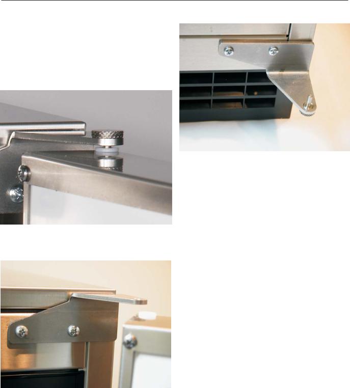
Sealing to floor: In some cases the base of the ice machine must be sealed to the floor to meet local code. Food grade silastic sealant such as Scotsman part number 19-0529-01 is recommended.
Place the machine in the intended location. Turn the leg levelers in until the bottom of the unit is as close to the floor as possible. Be sure the unit is level and all four levelers are in contact with the floor.
Place a bead of the sealant between the floor and the outside edge of the cabinet. The bead must fill the space between the cabinet bottom edges and the floor.
Built In Situations: If a finished floor is to be installed in the area after the ice machine has been built in, shims the expected thickness of the floor should be installed under the unit to keep the machine level with the planned floor level.
Installations on a slab: Use a pump model and pump the water to the point of drainage. Pump models will pump 1 story (10 feet) high.
Installations over a crawl space or basement: Either gravity drain or pump model units may be used, if there is not enough room behind the machine for a drain/waste receptacle, the drain will have to be below the floor.
Note: When installed in a corner, the door swing may be limited due to handle contact with the wall or cabinet face.
March 2010
Page 7
CU50
Service Manual
Installation: Water & Drain
The recommended water supply tubing is ¼ inch OD copper. Stainless steel flex or reinforced PVC tube may also be used. Install an easily accessible shut-off valve between the supply and the unit. This shut-off valve should not be installed behind the unit.
Note: Do not use self-piercing type valves.
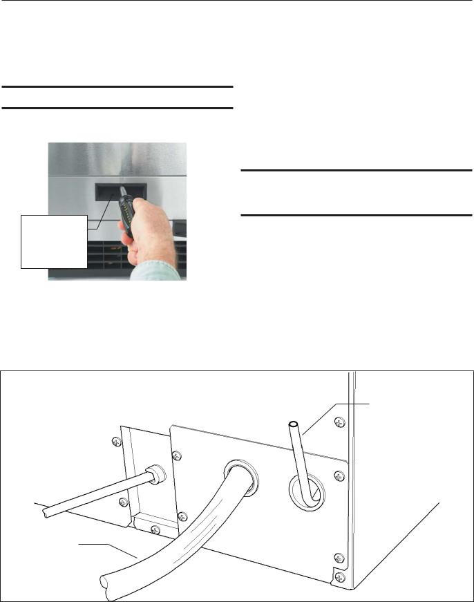
1. Remove the front service panel.
Screw
Securing
Front Service
Panel
2.Route the tubing through the right hole in the back to the inlet water solenoid valve inlet.
3.Install a compression fitting on the tubing and connect to the inlet of the solenoid.
Drains
There are two types of ice machine models, one that drains by gravity and one that has an internal drain pump.
Drain Pump Model drain installation
1.Locate the coil of 3/8” ID plastic drain tubing secured to the back of the unit.
2.Route the plastic drain tube from the back of the unit to the drain connection point.
IMPORTANT NOTE: Often an air gap is required by local codes between the ice maker drain tube and the drain receptacle.
Water Inlet Tube (field supplied)
Drain Tube, Route to building drain
Back View, Drain Pump Model
March 2010
Page 8
CU50
Service Manual
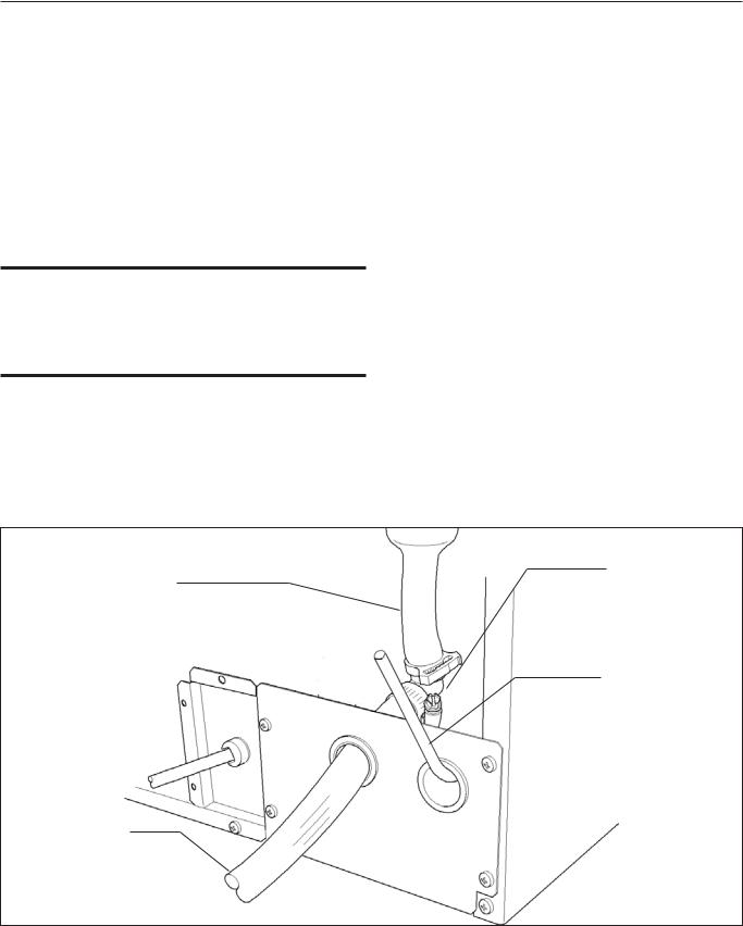
Gravity Drain
Caution: Restrictions in the drain system to the machine will cause water to back up into the ice storage bin and melt the ice. Gravity drain tubing must be vented, have no kinks and slope to the building drain. Air gaps are typically required by local code.
1.Place the ice machine in front of the installation opening. Adjust leveling legs to the approximate height.
2.Remove the front service access panel and the upper back panel.
Note: If you are connecting a gravity drain model and the drain opening has been located in the floor under the base pan according to the pre install specifications, follow steps 3 through 5 to drain the unit through the base. If not, proceed to step 6b.
3. Remove the clamp and barbed elbow and take off the plastic cover in the base pan below the drain hose.
4.Connect a straight 5/8” barbed connector to the drain hose, securing with the clamp removed in step 4.
5.Cut an 8” piece of 5/8” ID X 7/8” OD tygon (clear plastic) tubing. Slide one end of the tube onto the outlet of the barbed connector and secure with a clamp. Leave the other end of the tube lying on the floor of the base pan until the unit is positioned over the floor drain.
6.Route the drain tube. Either a) Insert the drain tube through the base pan into the floor drain or b) Route the drain tube through the left hole in the lower back panel and connect to barbed elbow and secure with a clamp.
7.Reinstall the upper back panel.
8.Reinstall the service access panel. Level the unit.
Barbed Elbow
Drain Hose
Water Inlet Tube (field supplied)
Drain Hose, Route to building drain
Back View, Gravity Drain Model
March 2010
Page 9
 Loading...