


CME306 & CME456
INTRODUCTION
This product manual contains the information needed for the setup, installation, initial start up, sanitation and maintenance of this ice machine. Keep it for future reference.
Be certain that the information applies to the model in question. If no model is listed, the information applies to all models.
This manual is organized in the same way as the expected use of the machine, it begins with specifications, goes thru unpacking and setup, shows where everything is; continues with initial start up, then describes how it works. After that is the sanitation section, followed by service diagnosis and repair.
CM Cubed™ Cuber Performance Raised to a Higher Power.™
™
|
|
|
|
|
|
|
|
|
|
|
|
TABLE OF CONTENTS |
|
|
|
|
|
|
|
|
|
Specifications · · |
· |
· |
· |
· |
· |
· |
· |
· |
· |
· |
· |
PAGE 2 |
Technicians Only: Freeze Cycle Operational |
||||||||
|
|
|
|
|
|
|
|
|
|
|
|
|
Sequence · · · · · · · · |
· |
· |
· |
· |
· |
· |
· |
PAGE 23 |
Air Cooled Layout |
· |
· |
· |
· |
· |
· |
· |
· |
· |
· |
· |
PAGE 3 |
|
|
|
|
|
|
|
|
|
|
|
|
|
|
|
|
|
|
|
|
|
|
Technicians Only: Harvest Cycle Operational |
||||||||
Water Cooled Layout |
· |
· |
· |
· |
· |
· |
· |
· |
· |
PAGE 4 |
Sequence · · · · · · · · |
· · |
· |
· |
· |
· |
· |
PAGE 24 |
|||
Pre-Installation · · |
· |
· |
· |
· · · |
· |
· |
· |
· |
· |
PAGE 5 |
Sanitation and Cleaning · |
· |
· |
· |
· |
· |
· |
· |
PAGE 25 |
||
Location · · · · · · · |
· |
· |
· |
· |
· |
· |
· |
· |
· |
PAGE 6 |
Additional Maintenance · |
· |
· |
· |
· |
· |
· |
· |
PAGE 26 |
||
On a Bin · · · · · |
· |
· |
· |
· |
· |
· |
· |
· |
· |
· |
· |
PAGE 7 |
Additional Maintenance: Ice Sensors |
· |
PAGE 27 |
||||||
On a Beverage Dispenser · |
· |
· |
· |
· |
· |
· |
PAGE 8 |
Additional Maintenance: Air Filter Replacement |
|||||||||||||
|
|
|
|
|
|
|
|
|
|
|
|
|
· · · · · · · · · · · · · · |
· |
· |
· |
· |
· |
· |
· |
PAGE 29 |
On a Motel Dispenser · |
· |
· |
· |
· |
· |
· |
· |
· |
PAGE 9 |
|
|
|
|
|
|
|
|
|
|||
|
|
|
|
|
|
|
|
|
|
|
|
|
Additional Maintenance: Condenser · |
· PAGE 30 |
|||||||
Cabinet Panel Removal: · |
· |
· |
· |
· |
· |
· |
· |
PAGE 10 |
|
|
|
|
|
|
|
|
|
||||
|
|
|
|
|
|
|
|
|
|
|
|
|
Service Diagnosis: Controller Diagnostic Light |
||||||||
Bin Thermostat: Optional Installation |
· |
PAGE 11 |
Analysis · · · · · · · · · |
· · |
· |
· · · |
· |
PAGE 31 |
|||||||||||||
Plumbing - Air Cooled · |
· |
· |
· |
· |
· |
· |
· · |
PAGE 12 |
Service Diagnosis · · · · |
· · |
· |
· · · |
· PAGE 32 |
||||||||
Plumbing - Water Cooled |
· |
· |
· |
· |
· |
· |
· |
PAGE 13 |
Service Diagnosis: Components· |
· |
· |
· |
PAGE 33 |
||||||||
Electrical · · · · · · · · |
· |
· |
· |
· |
· |
· |
· |
· |
PAGE 14 |
Service Diagnosis: PTCR |
· |
· |
· |
· · · |
· PAGE 34 |
||||||
After Utility Connections · |
· |
· |
· |
· |
· |
· |
· |
PAGE 15 |
Operational Characteristics: CME306 |
· |
PAGE 35 |
||||||||||
Component Description and Function · |
PAGE 16 |
Operational Characteristics: CME456 |
· |
PAGE 36 |
|||||||||||||||||
AutoIQ Controller · · · · · · · · · · · PAGE 17
How To Operate The AutoIQ Controller PAGE 18
Initial Start Up · · · · · · · · · · · · · PAGE 19
Adjustments · · · · · · · · · · · · · · PAGE 20
How This Machine Works · · · · · · · PAGE 21
How This Machine Works · · · · · · · PAGE 22
Removal and Replacement: Water Level Sensor
· · · · · · · · · · · · · · · · · · · · · PAGE 37
Removal and Replacement: Fan Blade and/or Fan Motor· · · · · · · · · · · · · · · · · · PAGE 38
Refrigeration · · · · · · · · · · · · · · PAGE 39
Before Calling for Service · · · · · · · PAGE 40
Parts Lists and Wiring Diagrams are Located in the Center of this Manual
January 2000
Page 1

CME306 & CME456
Specifications
This ice machine is designed to be installed indoors, in a controlled environment. It will operate satisfactorily under a wide variety of conditions. Do NOT operate the machine in temperatures it has not been designed for. Do NOT operate the machine above or below the voltage limits for the particular model. Do NOT operate the machine with too little or too much water pressure.
Operational Limits
|
Minimum |
Maximum |
|
|
|
Air Temperature |
50oF. |
100oF. |
Water Temperature |
40oF. |
100oF. |
Water Pressure |
20 psi |
80 psi |
|
|
|
Voltage (115 volt models) |
104 |
126 |
|
|
|
Voltage (208-230 v models) |
198 |
253 |
|
|
|
Voltage (50 Hz models) |
207 |
253 |
|
|
|
|
|
|
Inlet water flow required is 1.25 GPM.
All models will fit a standard, 22" wide Scotsman Ice Storage Bin such as the BH360.
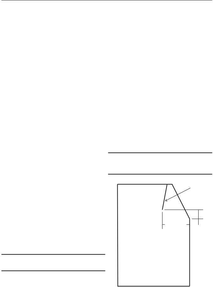
Note: Slope front bins may need an internal baffle. Scotsman’s BH360 has the required baffle. Baffle must be approximately in the position shown in the diagram on page 5.
Basic Information
Note: The ice machine will hang over the back of the Lancer dispensers shown in the following list.
In addition, there may be other bins that can be used, check Scotsman’s sales literature for application information.
Note: This unit may not be stacked.
Bin and Dispenser Applications & Kits:
•BH360 bin: Direct Fit
•HD22 dispenser: Direct Fit.
•ID150, add adapter kit KBT42
•ID200 or 250, add adapter kit KBT43
•Lancer 22” wide model: Add kit A37693-021.
•Lancer 30” wide model: Add kit KLD22-30.
•HTB555 - Add bin top kit KBT27
•Bin’s with short/no baffle require thermostat kit: KSTAT-22.
Scotsman reserves the right to make design changes and/or improvements at any time. Specifications and designs are subject to change without notice.
Scotsman assumes no liability or responsibility of any kind for products manufactured by Scotsman that have been altered in any way, including the use of any parts and/or other components not specifically approved by Scotsman.
|
|
Dimensions |
Basic |
Condenser |
Minimum |
Max |
Refrigerant |
|
Model Number |
Series |
W" x D" x H" |
Circuit |
Fuse* |
Charge |
|||
Electrical |
Type |
|||||||
|
|
(w/o bin) |
Ampacity |
Size |
(R-404A) |
|||
|
|
|
|
|||||
|
|
|
|
|
|
|
|
|
CME306AS-1 |
A, B or C |
22 x 24 x 28 |
115/60/1 |
Air Cooled |
16 |
20 |
23 ounces |
|
|
|
|
|
|
|
|
|
|
CME306AS-32 |
A, B or C |
same |
208-230/60/1 |
Air Cooled |
7.9 |
15 |
23 ounces |
|
|
|
|
|
|
|
|
|
|
CME306AS-6 |
A, B or C |
same |
230/50/1 |
Air Cooled |
15 |
15 |
23 ounces |
|
|
|
|
|
|
|
|
|
|
CME306WS-1 |
A |
same |
115/60/1 |
Water Cooled |
16 |
20 |
15 ounces |
|
|
|
|
|
|
|
|
|
|
CME306WS-32 |
B or C |
same |
208-230/60/1 |
Water Cooled |
7.4 |
15 |
13 ounces |
|
|
|
|
|
|
|
|
|
|
CME306WS-6 |
A |
same |
230/50/1 |
Water Cooled |
15 |
15 |
15 ounces |
|
|
|
|
|
|
|
|
|
|
CME306WS-1 |
B or C |
same |
115-60/1 |
Water Cooled |
16 |
20 |
13 ounces |
|
|
|
|
|
|
|
|
|
|
CME306WS-1 |
B or C |
same |
230/50/1 |
Water Cooled |
15 |
15 |
13 ounces |
|
|
|
|
|
|
|
|
|
|
CME456AS-1 |
A, B or C |
same |
115/60/1 |
Air Cooled |
19 |
20 |
24 ounces |
|
CME456AS-32 |
A, B or C |
same |
208-230/60/1 |
Air Cooled |
9.8 |
15 |
24 ounces |
|
|
|
|
|
|
|
|
|
|
CME456WS-1 |
A |
same |
115/60/1 |
Water Cooled |
19 |
20 |
17 ounces |
|
|
|
|
|
|
|
|
|
|
CME456WS-1 |
B or C |
same |
115/60/1 |
Water Cooled |
19 |
20 |
14 ounces |
|
|
|
|
|
|
|
|
|
|
CME456WS-32 |
B or C |
same |
208-230/60/1 |
Water Cooled |
9.2 |
15 |
14 ounces |
|
|
|
|
|
|
|
|
|
|
CME456AS-6 |
A, B or C |
same |
230/50/1 |
Air Cooled |
7.9 |
15 |
24 ounces |
|
|
|
|
|
|
|
|
|
|
CME456WS-6 |
A |
same |
230/50/1 |
Water Cooled |
7.1 |
15 |
17 ounces |
|
|
|
|
|
|
|
|
|
|
CME456WS-6 |
B or C |
same |
230/50/1 |
Water Cooled |
7.1 |
15 |
14 ounces |
|
|
|
|
|
|
|
|
|
|
|
|
|
|
|
|
|
|
* Or HACR circuit breakers.
May 2004
Page 2

CME306 & CME456
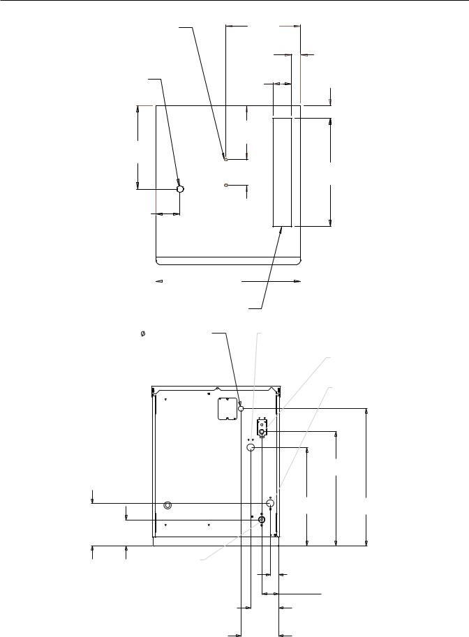
Air Cooled Layout
Bin Stat |
11.38 in |
|
|
Bracket |
28.9 cm |
|
|
Mounting |
|
|
|
Holes |
1.25 in |
|
|
|
|
||
|
3.2 cm |
|
|
Bin Stat |
|
1.75 in |
|
Thru Hole |
2.63 in |
||
4.4 cm |
|||
|
6.7 cm |
||
|
|
||
|
8.75 in |
|
|
|
22.2 cm |
|
|
12.88 in |
|
|
|
32.7 cm |
|
|
|
|
4.00 in |
16.7 in |
|
|
10.2 cm |
||
|
42.4 cm |
||
|
|
3.75 in
9.5 cm
Plan View
22.00 in
55.9 cm
Ice Opening
AIR COOLED
CONDENSER
BACK VIEW
.88 DIA. HOLE ELECTRICAL INLET
WATER INLET 3/8" FLARE
|
|
6.22 in |
3.72 in |
4.24 in |
15.8 cm |
|
||
|
|
|
9.5 cm |
10.8 cm |
|
|
|
SUMP DRAIN
3/4" F.P.T. 3.16 in 8.0 cm
6.40 in
16.3 cm
9.15 in
23.2 cm
January 2000
Page 3
CME306 & CME456
Water Cooled Layout
Bin Stat |
11.38 in |
|
|
Bracket |
28.9 cm |
|
|
Mounting |
|
|
|
Holes |
1.25 in |
|
|
|
|
||
|
3.2 cm |
|
|
Bin Stat |
|
1.75 in |
|
Thru Hole |
2.63 in |
||
4.4 cm |
|||
|
6.7 cm |
||
|
|
||
|
8.75 in |
|
|
|
22.2 cm |
|
|
12.88 in |
|
|
|
32.7 cm |
|
|
|
|
4.00 in |
16.7 in |
|
|
10.2 cm |
||
|
42.4 cm |
||
|
|
3.75 in
9.5 cm
Plan View
|
|
|
22.00 in |
|
|
|
|
55.9 cm |
|
|
|
Ice Opening |
||
.88 DIA. HOLE |
|
CONDENSER INLET |
||
ELECTRICAL INLET |
|
3/8" F.P.T. |
||
|
|
|
||
WATER INLET 3/8" FLARE
CONDENSER DRAIN 1/2" F.P.T.
BACK VIEW
19.99 |
in |
50.8 cm |
|
17.17 in |
24.02 in |
43.6 cm |
61.0 cm |
7.39 in
18.8 cm 4.54 in
11.5 cm
SUMP DRAIN 3/4" F.P.T.
1.43 in
3.6 cm
2.93 in
7.4 cm
4.92 in
12.5 cm
6.60 in
16.8 cm
January 2000
Page 4
CME306 & CME456
Pre-Installation
Other Applications:
Check Scotsman sales information for recommendations regarding applications.
Do not place Air Cooled models where the noise from the fan(s) will be objectionable.
Check the nameplate for electrical requirements. The nameplate is located on the back of the ice machine. While the model and serial number are on the nameplate, a serial number plate is located at the front of the machine, near the controller.
Water:
There is no such thing as pure water. All water contains some impurities. There are two ways water carries the impurities: suspended and dissolved. Suspended solids can be filtered out. Dissolved solids must be diluted or treated. Water filters are recommended to remove suspended solids. Some filters also have treatment in them for dissolved solids. Check with a water treatment service for a recommendation.
Cube Ice machines use more water than what ends up in the bin as ice. While most water is used during ice making, a portion is designed to “rinse" out the water system to keep hard water scale from clogging up the machine. That water rinse, combined with water filters, prolongs the times between needed water system cleaning.
Note: All Scotsman CM3 models, like those described in this manual, feature Scotsman’s AutoIQ™ control system and ReliaClean™ water system cleaning process.
Nameplate on Back Panel
Serial Number Plate, Remove
Front Panel to Locate
Note: Slope front bins must have an internal baffle. Scotsman’s BH375 has the required baffle. Baffle must be approximately in the position shown in the diagram.
Baffle
Service Technicians: All models covered here come set from the factory at a “standard” water rinse, which is compatible with typical water conditions. They may be adjusted to “Minimum" or “Maximum" water rinse after start up. If the prior ice machine worked acceptably well with the local water conditions, leave the machine at the factory setting. If severe water conditions are present, and water filters do not solve the problem acceptably, adjust the machine to use more water. If water conditions are excellent, adjust the machine to use less water. See the Adjustments section.
Note: Water use adjustments are customer convenience adjustments; they are NOT factory defects and are NOT covered by warranty.
12.0"
Side View
4.0"
January 2000
Page 5
CME306 & CME456
Location
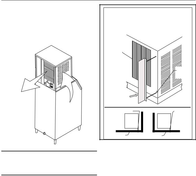
Air cooled models take room temperature air in from the left side and discharge warm air out the back. Do not place them where the heat and noise will be objectionable.
A 6 inch MINIMUM clearance between the back and a wall and between the left side and a wall or another product is required for the basic operation and service of the air cooled model.
Airflow is in the left side and out the back
Note: A six inch side clearance with zero top clearance will NOT provide enough air exchange space for optimum performance. 12 inches side clearance is required when there is no top clearance.
Remove Air Baffle from its |
|
Shipping Position. |
|
Use baffle for |
|
In-The-Corner Applications |
|
|
Back View of Ice |
|
Machine |
Condenser |
|
Outlet |
|
|
Attach |
|
Baffle |
|
Here |
Air |
|
Baffle |
|
Baffle Position |
Baffle |
Ice Machine |
Ice Machine |
Top View |
Top View |
Wall |
Wall |
Air cooled models come equipped with a baffle that can be used when the machine is installed in a corner.
The purpose of the baffle is to limit air recirculation. This can occur in a corner when the hot air from the back of the machine is re-drawn back into the machine from the nearest side of the machine.
Install the air baffle as shown on the left rear corner when a side wall and back wall are between 6 and 18 inches from the unit.
January 2000
Page 6
CME306 & CME456
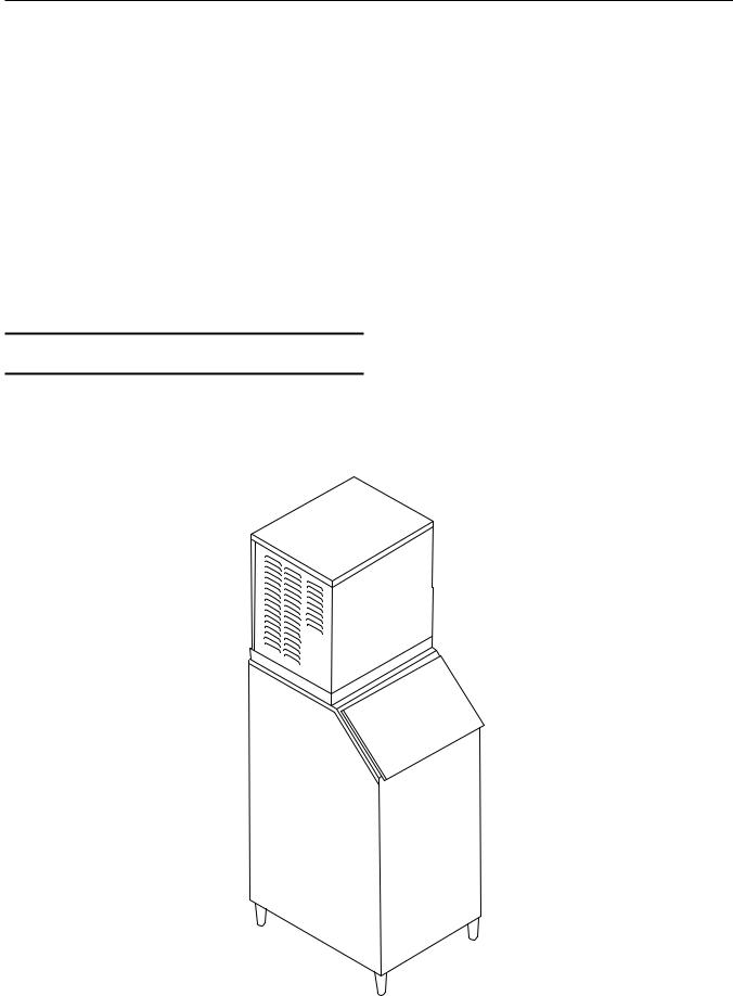
On a Bin
Unpacking and Assembly: |
Application Notes: |
Begin with unpacking the ice storage bin. Remove the carton, and using part of the carton as a cushion, tip the bin on its back to remove the skid and attach the legs or casters.
Return the bin to an upright position. Check the bin top gasket for gaps and tears, fill any in with food grade sealant prior to placing the ice machine on the bin.
Level the top edge of the bin front to back and left to right.
If the ice machine has not been unpacked, do so now. Remove the carton from the skid. After removal of the shipping straps, lift the ice machine off the skid directly onto the bin.
Note: The machine is heavy! Use a mechanical hoist if necessary.
Secure the ice machine to the bin with the hardware provided (two metal straps and 4 bolts).
No thermostat is required for any of the following bins.
BH375: Direct fit. Connect ice machine to bin using strap and bolts from ice machine for the ice machine side, and sheet metal screws to attach the bracket to the bin. Use the bracket as a template and drill two holes in the back of the bin for the sheet metal screws.
HTB555: Use KBT27
BH550: Use KBT27 and Kbaffle1
Other Brand’s Bins: KBT27 may allow installation of this unit on a non-Scotsman 30” wide bin. Thermostat kit KSTAT-22 must be used if the bin’s baffle is too short.
May 2004
Page 7
CME306 & CME456
On a Beverage Dispenser
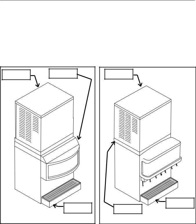
The CME306 or CME456 will mount on top of many brands of ice and beverage dispensers. The brands include Scotsman, Cornelius and Lancer.
Scotsman and Cornelius use the same adapter kits. 22” wide ice dispensers use KBT42, while 30” wide units use kits KBT43.
A bracket kit (A37693-021) is required to connect and secure the CME306 or CME456 to the Lancer 22” wide ice or ice and beverage dispenser.
No thermostat is required in any of the above.
A bracket and filler plate kit (KLD22-30) is required to connect and secure the CME306 or CME456 to the Lancer 30” wide ice or ice and beverage dispenser. It includes a thermostat and bracket.
Other dispensers may require their own adapter kits. Contact Scotsman or a Scotsman Distributor for additional information.
Ice Machine |
Adapter |
|
|
|
Dispenser |
On Scotsman Dispenser
Ice Machine |
Dispenser |
Bracket |
On a Lancer Dispenser
May 2004
Page 8
CME306 & CME456
On a Motel Dispenser
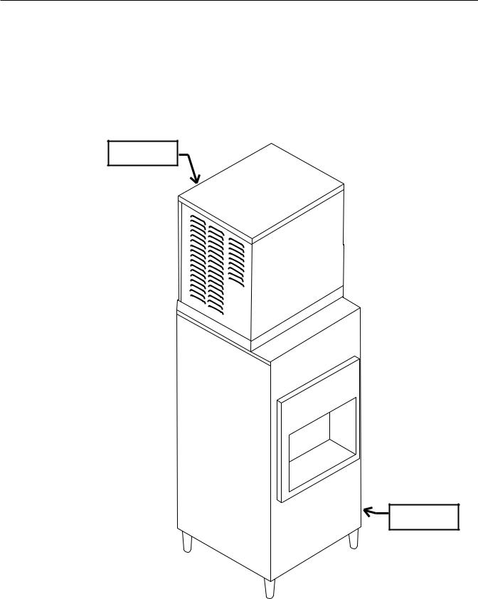
Either the CME306 or the CME456 may be placed on a Motel Dispenser.
No thermostat is required when used on either the
SLD150 or the HD150, or HD156 or HD22.
Scotsman model SLD150 may be used, but the back portion of the top must be removed and replaced with the KDT22 kit.
The Scotsman HD22 is a direct fit.
Ice Machine
Dispenser
May 2004
Page 9
CME306 & CME456
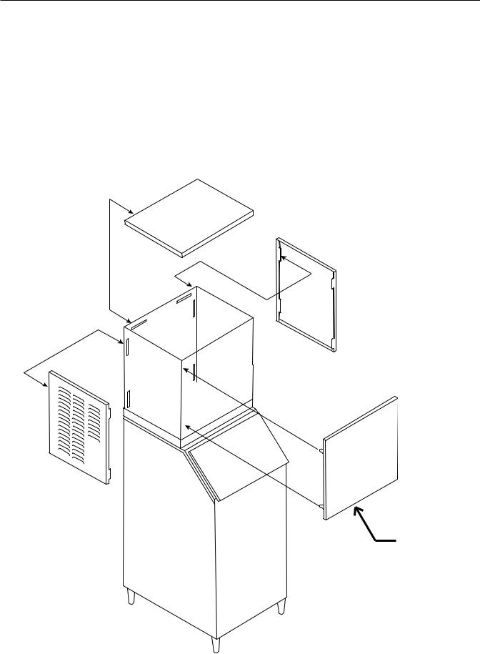
Cabinet Panel Removal:
Note: The top panel holds the upper edges of the side panels in place.
1.Remove the front panel by removing the two screws connecting the top edge of the front panel to the machine, then pull out at the bottom.
2.Lift up at the front edge and push the top panel back until it releases from the tabs connecting it to the side panels.
3.Remove the screws at the front edge of the left side panel, and push it back until it releases from the tabs connecting it to the back panel.
Remove The
Front Panel
First
January 2000
Page 10

CME306 & CME456
Bin Thermostat: Optional Installation
The normal bin control is the ice sensor set. An option, required in some cases, is a thermostat. Its bulb must be deployed after the ice machine has been placed on the bin or dispenser.
Note: Some configurations may have parts that vary from these instructions. Follow the instructions for the particular configuration.
Before starting, remove the left side panel and any baffle in the bin.
1. Place thermostat in machine behind the high voltage box and secure to the existing holes with two screws. Locate bin thermostat bulb.
4. Carefully position the thermostat bulb on the bracket.
Thermostat
Body
2. Route bulb thru routing hole (located behind the compressor).
Routing Hole
Insert Tip
5. Fasten the bracket to the bottom of the ice machine with the two 3-pronged knobs supplied with the kit.
Bin
Thermostat
Bracket
6.Pull excess capillary tubing into the machine..
7.Continue with the installation. If a baffle was removed return it to its original position.
Note: If the machine is located at an altitude higher than 2,000 ft., adjust the thermostat by removing the plastic cover and rotating the adjustment screw per the table.
Bin Thermostat Altitude Correction Table
CW Turns of Range Screw (under plastic cover)
Feet |
Turns |
Feet |
Turns |
|
|
|
|
2000 |
55o |
8000 |
340o |
4000 |
160o |
9000 |
385o |
3. Locate bin thermostat bracket.
Use This Table to Adjust Thermostat
January 2000
Page 11
CME306 & CME456
Plumbing - Air Cooled
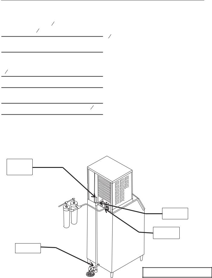
All models require an adequate potable water supply and a gravity drain. The recommendations for tubing are:
All Drain Tubing Material must be RIGID. Flexible tubing will eventually cause a restricted drain.
•Water supply to be 3 8" OD.
•Drain to be 3 4" OD.
Note: When replacing a prior ice machine, do not take a short cut and reuse the old inlet and drain system. INSTALL A NEW SYSTEM.
Supply:
Air cooled models have 1 water supply connection, a 3 8" male flare at the back of the cabinet.
Exception: WRAS listed units have a 3/4" GAS or BSPP water inlet fitting size.
Connect to cold potable water that has adequate pressure.
Note: Using water supply tubing smaller than 3 8" will cause severe operational issues.
Water Filters:
The water filters must flow at least 1.25 GPM or they will cause severe operational issues. Check with the filter manufacturer. When replacing a prior ice machine, do NOT assume that the water flow capacity of the filter will be adequate.
Drain:
Air cooled models have 1 gravity drain connection, a 3 4" FPT fitting at the back of the cabinet. Use only RIGID TUBING. Flexible tubing may be easily kinked or become cracked.
The drain tube must be vented at the back of the cabinet. Use an 18" high vent.
The ice storage bin will have a drain out the back or base, depending upon the model.
The drain for the ice machine and the ice storage bin must be SEPARATE or the ice machine’s drain water may run into the bin and MELT THE ICE.
Insulation is recommended for the ice machine reservoir and bin drains.
Follow all applicable codes
Vent this
Drain
Water OUT
Water IN
Bin Drain
Plumbing Connections
November 2005
Page 12
 Loading...