


CME250
Introduction
To the owner or user: This service manual is intended to provide you, and the maintenance or service technician, with the information needed to install, start up, clean, maintain and repair this product.
The CME250 is an ice machine that produces cubed ice on 2 vertical cube freezing surfaces. The cubes fall as vertical strips of cubes into the ice storage bin where they break up into individual cubes. The CME250 automatically maintains the level of ice by turning on when the ice level falls, and switches off when the bin is full.
The refrigeration system uses HP62 as the refrigerant. HP62 models use polyolester refrigerant oil.
Information on HP62 is located on page 23.
Table of Contents
Specifications . . . . . . . . . . . . . . . . . . . . . . . . . . . . . . . . . . . . |
. . . . . . . . . . . . page 2 |
Limitations . . . . . . . . . . . . . . . . . . . . . . . . . . . . . . . . . . . . . |
. . . . . . . . . . . . page 3 |
Installation . . . . . . . . . . . . . . . . . . . . . . . . . . . . . . . . . . . . . |
. . . . . . . . . . . . page 4 |
Plumbing . . . . . . . . . . . . . . . . . . . . . . . . . . . . . . . . . . . . . . |
. . . . . . . . . . . . page 6 |
Final Check List . . . . . . . . . . . . . . . . . . . . . . . . . . . . . . . . . . |
. . . . . . . . . . . . page 8 |
Component Location . . . . . . . . . . . . . . . . . . . . . . . . . . . . . . . . |
. . . . . . . . . . . . page 9 |
Initial Start Up . . . . . . . . . . . . . . . . . . . . . . . . . . . . . . . . . . . . |
. . . . . . . . . . . . page 11 |
Electrical Sequence . . . . . . . . . . . . . . . . . . . . . . . . . . . . . . . . |
. . . . . . . . . . . . page 12 |
Cleaning . . . . . . . . . . . . . . . . . . . . . . . . . . . . . . . . . . . . . . |
. . . . . . . . . . . . page 13 |
Water/ Refrigeration Schematic . . . . . . . . . . . . . . . . . . . . . . . . . . |
. . . . . . . . . . . . page 16 |
Technical Characteristics . . . . . . . . . . . . . . . . . . . . . . . . . . . . . . |
. . . . . . . . . . . . page 18 |
Service Diagnosis . . . . . . . . . . . . . . . . . . . . . . . . . . . . . . . . . |
. . . . . . . . . . . . page 19 |
Removal and Replacement . . . . . . . . . . . . . . . . . . . . . . . . . . . . |
. . . . . . . . . . . . page 21 |
Refrigeration Service . . . . . . . . . . . . . . . . . . . . . . . . . . . . . . . . |
. . . . . . . . . . . . page 23 |
Parts lists and wiring diagrams are located in the |
|
center of this manual, printed on yellow paper. |
|
Note the warning symbol where it appears in this |
|
manual. It is an alert for important safety |
|
information on a hazard that might cause serious |
|
injury. |
|
Keep this manual for future reference. |
|
This manual was printed on recycled paper.
August 1994
Page 1

CME250 |
|
Specifications |
|
Information regarding Model Number, Serial |
|
Number, Ampacity and Maximum Fuse Size are |
|
located on the nameplate of the ice machine. The |
|
model number, serial number and refrigerant |
|
charge are also listed on |
|
the serial number plate |
|
just behind the front |
|
panel. |
Serial Number |
Nameplate |
|
If recharging, always |
Plate |
use the charge listed on |
|
the ice machine. |
|
The CME250 will stack onto a variety of Scotsman
ice storage bins: ∙*BH550
CME250 Cabinet
∙*HTB500, HTB350, HTB250
∙BH800 (with bin top KBT23)
∙BH900 (with bin top KBT22)
∙BH1360
It will also fit these Scotsman Dispensers: ∙CD200
∙IS150 (with KADCM1)
∙RS150 (with KADCM1)
* These smaller bins are recommended.
There is an optional stainless steel panel kit,
SPKCMD-1, for this machine.
Specifications:
Model Number |
Dimensions |
Condenser |
Basic |
Minimum |
Maximum Fuse |
Refrigerant |
|
W" x D" x H" |
Type |
Electrical |
Circuit |
Size (or HACR |
Charge. HP62 |
|
|
|
|
Ampacity |
circuit breakers) |
|
|
|
|
|
|
|
|
CME250AE-1E |
30 x 24 x 27 |
Air |
115/60/1 |
16 |
20 |
27 ounces |
|
|
|
|
|
|
|
CME250WE-1E |
30 x 24 x 27 |
Water |
115/60/1 |
16 |
20 |
17 ounces |
|
|
|
|
|
|
|
|
|
|
|
|
|
|
October 1994
Page 2

CME250
For The Installer: Environmental Limitations
The ice machine must be installed indoors in a controlled environment.
|
Minimum |
Maximum |
Air Temp |
500F. |
1000F. |
Water Temp |
400F. |
1000F. |
Water Pressure |
20 PSI |
80 PSI |
Voltage |
103.5 |
126.5 |
Operating the ice machine outside of the above limitations, or outdoors, is potentially damaging to the machine, and it is misuse of the machine. This may void the warranty.
Scotsman Ice Systems are designed and manufactured with the highest regard for safety and performance. They meet or exceed the standards of UL, NSF, and CSA.
Scotsman assumes no liability or responsibility of any kind for products manufactured by Scotsman that have been altered in any way, including the use of any part and/or other components not specifically approved by Scotsman.
Scotsman reserves the right to make design changes and/or improvements at any time.
Specifications and design are subject to change without notice.
Airflow on air cooled models is:
∙Intake through the right side grill.
∙Exhaust through the left side grill.
Do not install where this air flow is obstructed. 6 inch clearance is required at the sides and back.
August 1994
Page 3

CME250
Installation
Water
The water supply for this ice machine has been in contact with many materials since it fell from the sky as rain. All rain is slightly acidic, and tends to dissolve the materials it comes in contact with. During water’s journey to the ice machine, it has flowed over and through the ground, been picked up by a municipal or private pump, forced through a series of pipes of differing construction and may have been treated by the municipality providing the water.
The water supplied to this ice machine will then contain a variety of substances that will likely show up as solids during the ice making process. These solids are similar to those found when water is boiled out of a saucepan. Only the water boils away, and the minerals that were in the water solidify in the pan. During ice making only the water is frozen into ice, the minerals stay behind in the reservoir. This machine pumps out the water in the reservoir every cycle to minimize the amount of minerals in the water system, but after time the minerals will appear and have to be dissolved by ice machine cleaner, then flushed away during the cleaning process.
An ice machine is a food manufacturing plant; it takes a raw material, in this case water, and transforms it into a food product, ice. The purity of the water is very important in obtaining pure ice and in maximizing product life.
The water to the ice machine should be filtered. Water filters vary greatly in ability and function. Install one that filters out suspended solids to a dimension of 5 microns or less. The finer the filter the better, but finer filters may plug-up sooner than course ones. It may be necessary to add a course filter ahead of the fine filter to prolong filter life.
Have the water tested. Acidic water or alkaline water will both cause corrosion. Dissolved solids cannot be filtered out. Check with a water treatment specialist regarding testing, treatment and filters.
Air cooled models blow air in and out through the grills at the sides (in the right and out the left). Space is required for air flow at the sides and utility connections at the back.
The ice machine is not designed for outdoor use. It must be installed indoors, in a controlled environment. The air and water temperatures must not exceed rated limits.
Pre-installation:
1. Inspect the place where the ice machine is to be installed. Check for:
∙space for the cabinet,
∙water supply,
∙drain availability
∙and electrical power supply.
No extension cords are allowed. The building drain inlet must be lower than the drain outlet of the ice bin. The water supply must have a hand shut off valve accessible when the unit is installed.
October 1994
Page 4

CME250
Installation
Assembly:
1.Attach the legs, or optional casters, onto the ice storage bin. Units that are stacked should only use legs, not casters.
2.Place the ice machine onto the storage bin.
3.Line up the ice machine, check that there is a good seal between the ice machine and the storage bin.
4.If on a Scotsman bin, attach the ice machine to the bin using the straps and bolts shipped with the ice machine. If on another brand bin, follow the directions included with that bin.
Bin Thermostat Installation:
1.Remove rubber cap from the end of the thermostat bracket.
2.Attach the bin thermostat bracket to the bottom of the ice machine using the thumb screws provided. There are pre-drilled and tapped holes located just behind the cube drop area. The end of the bin thermostat bracket with the plastic tubing on it will fit into the hole in the base of the machine.
3.Locate and uncoil a portion of the bin thermostat capillary tube. Route the end of the capillary tube into and through the bin thermostat bracket tube. It should be inserted the full length of the tube, but not past the end.
Stacking:
This machine will stack onto any CME250, CME250, CM450, CM500, CME500, CM650 or CME650 with the same cabinet depth (24").
1.Remove and discard the top panel from the lower unit.
2.Carefully lift the uncrated top unit onto the bottom unit. Use of a mechanical lift is recommended for this step.
3.Align the two ice maker cabinets.
4.Secure the top unit to the bottom one with the hardware and straps shipped with the upper machine.
5.Locate and uncoil all of the bin thermostat capillary tube.
6.Route the bin thermostat capillary tube from the upper unit, through the hole in the back of the reservoir, through the lower unit and into the bin thermostat bracket. Discard upper unit bracket.
Bin Thermostat
Installation
Thermostat
Capillary Tube
Bin Thermostat
Bracket
Stacking
Capillary Tube
Strap
Routing Hole
Reservoir
Bin Thermostat Bracket
August 1994
Page 5
CME250
Installation
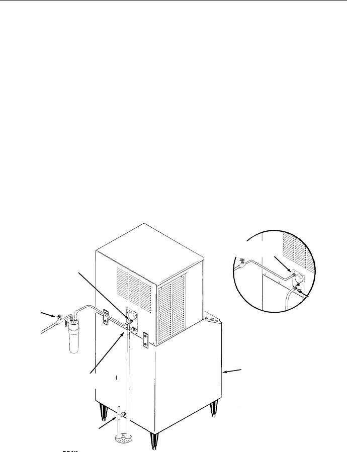
For The Plumber
1. Connect cold potable water to the 3/8" male flare at the back of the cabinet. A water filter is recommended. Flush the water line prior to connecting to the ice machine.
If water cooled, connect a separate water inlet line to the water cooled condenser inlet fitting. It should also have a hand shut off valve.
A loop of copper tubing may be used between the ice machine and the water supply. This will allow the ice machine to be pulled out from its installed location without disconnecting the water line. No back-flow preventer should be needed in the inlet potable water line because provision for that is incorporated in this N.S.F. listed product (the tube from the inlet water valve has an air break in it, is above the reservoir wall and cannot siphon).
2. Connect a drain tube to each drain. The drain tubes from these connections must be run separately. There are two connections, one is the bin drain and the other is the reservoir drain. The reservoir drain is a 3/4" F.P.T. brass fitting.
Drain tube material must be rigid and meet local code.
Traps in the bin drain line without vents ahead of them will cause poor draining.
The bin drain must be vented if there is a long horizontal run (5’ or more). The reservoir drain must be vented and not connected to the bin drain. All drains are gravity, and must have a minimum fall of 1/4" per foot of horizontal run. The water cooled condenser drain is not vented, and is routed separately.
Maintain the air gap required by local code between the end of the drain tubes and the building drain receptacle.
Note: Drain tubing should be insulated to prevent condensation from forming on the tubing.
CONFORM TO ALL LOCAL CODES
3/8" FPT Inlet
3/8 Male Flare
Water Inlet
Water Shut
1/2" FPT
Off Valve
Outlet
Water Cooled
Condenser Plumbing
Connections
Reservoir Drain |
Ice Storage Bin |
(Typical) |
|
3/4" FPT, Must Be Vented. |
|
Bin Drain. May Be Routed From |
|
The Bottom On Some Model |
Water Supply and Drain Connections |
Bins. Fitting May Be Plastic. |
|
DO NOT OVERHEAT. |
|
|
October 1994 |
|
Page 6 |
CME250
Installation
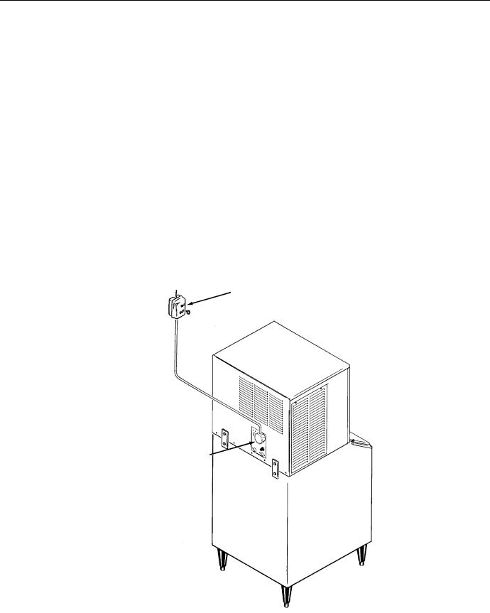
For The Electrician
This unit must be on a separate 115 volt AC 60 cycle single phase power supply. The maximum fuse size for this circuit is listed on the nameplate, and per the nameplate use fuses, or HACR circuit breakers.
Electrical connections are made at the rear of the ice maker, inside the junction box.
Recommendation: If using wire nuts, cut "tinned" portion of connecting wires off and strip 1¤2" of insulation from the end of each wire.
Follow All Local Codes - This Unit Must Be Grounded. Usually a licensed electrician will be required to connect the electrical service.
Hand Disconnect Switch
Junction Box
August 1994
Page 7

CME250
After Utility Connections
1.Level the cabinet, use the leg levelers on the end of the legs to adjust the cabinet height. (Legs should have been installed when the bin was unpacked).
2.Wash out the bin. If desired, the interior of the bin could be sanitized.
Final Check List
1.Is the ice maker cabinet in a room where ambient temperatures are within the minimum and maximum temperatures specified?
2.Has the water supply been connected?
3.Is the water pressure adequate?
4.Have the water connections been checked for water leaks?
5.Have the drain connections been made?
6.Have the drain connections been checked for leaks?
7.Is the cabinet level?
8.Is the ice machine connected to a 115 volt electrical power supply and is the ice machine the only load on that circuit?
9.Has all of the shipping material been removed from the inside of the cabinet?
10.Has the bin thermostat bracket been attached to the bottom of the ice machine, and the capillary tube routed thru the bracket?
11.Has the bin and cabinet been wiped clean and sanitized?
12.Has the Customer Evaluation & Warranty Registration form been properly filled out? Check for correct model and serial numbers from the nameplate, then mail the completed form to Scotsman.
13.Has the owner/user been given the name and telephone number of the authorized Scotsman Service Agency serving that location?
October 1994
Page 8
 Loading...